Operating instructions ECE ECG ECH ECI ECR - ENEMAC GmbH
Operating instructions ECE ECG ECH ECI ECR - ENEMAC GmbH
Operating instructions ECE ECG ECH ECI ECR - ENEMAC GmbH

You also want an ePaper? Increase the reach of your titles
YUMPU automatically turns print PDFs into web optimized ePapers that Google loves.
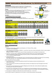
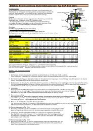
<strong>ENEMAC</strong> <strong>Operating</strong> <strong>instructions</strong> Torque Limiters types <strong>ECE</strong> <strong>ECG</strong> <strong>ECH</strong> <strong>ECI</strong> <strong>ECR</strong><br />
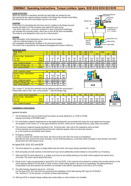
mode of function<br />
When the machine is operating normally the steel balls are pressed by the<br />
disk spring into the cupped recesses located in the flange ring, thereby transmitting<br />
the torque from the hub to the flange ring and vice-versa.<br />
overload<br />
In the event of overloading the hub turns round in relation to the flange ring and<br />
presses the balls out of the recesses back against the disk spring<br />
- the clutch clicks over - (once per revolution in case of fixed point switching)<br />
and actuates the proximity switch, which has to shut off the drive immediately.<br />
The clutch is only designed to click over for a short period !<br />
engage<br />
After elimination of the disturbance, the clutch has to be rotated<br />
- with low rotational speed or by hand -<br />
and reengages automatically (audible) in the fixed point position.<br />
The clutch now is operational, the adjusted disengagement torque is effective.<br />
flange ring<br />
h<br />
hub<br />
h<br />
seat for<br />
sliding<br />
bearing<br />
<strong>ECR</strong><br />
<strong>ECE</strong><br />
<strong>ECG</strong>/<strong>ECI</strong><br />
switching distance<br />
proximity<br />
switch<br />
threaded pin as<br />
axial fixation<br />
in „L“ version<br />
adjustment nut<br />
disk spring<br />
steel balls<br />
technical data<br />
<strong>ECE</strong> <strong>ECG</strong> 5 10 16 25 40 63 100 200 315 630 900<br />
<strong>ECI</strong> 5 10 16 25 40 63 100 200 315 630 900<br />
torque range (adjustable)<br />
TA max (Nm)<br />
TA min (Nm)<br />
5<br />
2<br />
10<br />
4<br />
16<br />
7<br />
25<br />
10<br />
max. rotational speed (min -1 ) 3000 3000 3000 3000 3000 3000 2500 2500 1800 1800 1800 1800 1800<br />
thread of flange ring h 6x M5 M5 M6 M6 M6 M6 M6 M6 M8 M10 M8 M10 M10<br />
max. screw position i (mm) 6 6 8 8 8 8 12 12 15 15 15 15 15<br />
<strong>ECR</strong> (stainless steel) 50 100 160 240<br />
torque range (adjustable)<br />
TA max (Nm)<br />
TA min (Nm)<br />
50<br />
15<br />
100<br />
40<br />
160<br />
60<br />
240<br />
100<br />
max. rotational speed (min -1 ) 3000 3000 2500 2500<br />
thread of flange ring h 6x M6 M6 M8 M8<br />
max. screw position i (mm) 8 8 12 12<br />
The screws h for the drive element must be tightened with the usual torque !<br />
Please take notice of the max. screw position i (into the flange ring).<br />
<strong>ECH</strong> (chain wheel integrated) 5 16 25 40 63 80 140 200 400 630 900<br />
torque range (adjustable)<br />
TA max (Nm)<br />
TA min (Nm)<br />
5<br />
2<br />
16<br />
6<br />
25<br />
10<br />
max. rotational speed (min -1 ) 3000 3000 3000 2800 2800 2500 2500 2000 2000 1500 1500<br />
installation <strong>instructions</strong><br />
general remarks<br />
1. The fit between the hub and shaft should be chosen as close sliding fit (e. g. H7/j6 or G7/k6).<br />
Keyway according to DIN 6885 sheet 1.<br />
2. For axial fixation (against displacement on the shaft) threaded pins are provided that clamp the hubs against the keyways.<br />
An exception is the version „K“ in the types <strong>ECE</strong>/<strong>ECG</strong> and <strong>ECI</strong>, which are for example fixed by a stop collar and washer.<br />
3. The maximum rotational speeds specified in the Technical data refer only to the respective clutch by itself.<br />
If drive elements are incorporated that permit lower rotational speeds, these are obviously decisive,<br />
(e. g. the maximum permissible chain speed).<br />
40<br />
16<br />
4. Emergency switching<br />
In order to protect the machine and clutch, the drive must be shut off in the event of overloading !<br />
Normally the disk spring of the clutch activates, via the switching distance, a proximity switch arranged in axial direction and which<br />
disconnects the motor power circuit.<br />
for types <strong>ECE</strong>, <strong>ECG</strong>, <strong>ECI</strong> and <strong>ECR</strong>:<br />
5. The drive element (e. g. pulley) is simply bolted onto the clutch, the torque being transmitted by friction.<br />
6. <strong>ECE</strong> and pulley are both centred on the shaft and must not be additionally centred relative to one another by a fit bearing.<br />
7. With type <strong>ECE</strong> the drive element (e. g. pulley) must have its own sliding bearing on the shaft, which supports the tractive force<br />
of the belt. The clutch cannot absorb this force.<br />
8. Points 6 and 7 apply as appropriate to types <strong>ECG</strong>, <strong>ECI</strong> and <strong>ECR</strong>. In this case the drive element is centred and mounted directly on the<br />
clutch bearing instead of on the shaft. In order to have a lower sliding speed in the event of overloading, the sliding bearing is<br />
incorporated in the drive element (is therefore not included in the delivery specification of the <strong>ECG</strong>, <strong>ECI</strong> or <strong>ECR</strong>).<br />
9. The slide bearing clearance has to be < 0,03 mm.<br />
For the types <strong>ECG</strong>, <strong>ECI</strong> and <strong>ECR</strong> we recommend the installation of the slide bearing SKF type GLYCODUR F.<br />
The tolerance f 7 of the bearing is matched to these slide bearings.<br />
10. With type <strong>ECE</strong> an adapter flange enables also small pulleys or chain wheels to be installed.<br />
40<br />
16<br />
63<br />
25<br />
63<br />
25<br />
80<br />
32<br />
100<br />
40<br />
140<br />
56<br />
200<br />
80<br />
200<br />
80<br />
315<br />
140<br />
400<br />
160<br />
315<br />
140<br />
630<br />
280<br />
630<br />
280<br />
900<br />
400<br />
630<br />
280<br />
900<br />
400<br />
<strong>ECH</strong>
<strong>ENEMAC</strong> <strong>Operating</strong> <strong>instructions</strong> Torque Limiters types <strong>ECE</strong> <strong>ECG</strong> <strong>ECH</strong> <strong>ECI</strong> <strong>ECR</strong><br />
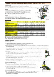
adjustment of disengagement torque TA<br />
The disengagement torque TA is continuously adjustable (without change the disk spring) !<br />
Special torque ranges on request.<br />
The couplings are pre-set by the manufacturer on assembly at about 70%<br />
of the maximum torque.<br />
The torque can be subsequently adjusted by turning the adjustment nut with a<br />
sickle spanner. Loosen the Allen set screws beforehand !<br />
IMPORTANT ! The characteristic curve of the disk spring is diminishing<br />
within the setting range !<br />
range of adjustment<br />
Opposite to the common practice this results in the effect,<br />
that turning the adjustment nut ...<br />
clockwise ⇒ TA decreases<br />
counter-clockwise ⇒ TA increases<br />
(see illustration to the right and foot)<br />
adjustment nut<br />
hub<br />
Allen set screws<br />
marking<br />
torque TA<br />
characteristic curve<br />
of disk spring<br />
released<br />
operating range<br />
setting range<br />
MAX<br />
switching<br />
distance<br />
MIN<br />
spring distance<br />
plan surface<br />
arrangement of disk spring<br />
The marking on the hub (see illustration to the left) must be between MIN and MAX in the<br />
adjustment range (=greater part of the circumference of the adjustment nut).<br />
By no means adjust torque below MIN, because in that case the disk spring will be blocked<br />
during disengagement, and the coupling will not operate.<br />
After adjustment the nut has to be fixed against turning by means of the Allen set srews<br />
(fixed with LOCTITE 222 or similar).<br />
<strong>ENEMAC</strong> <strong>GmbH</strong> Daimler Ring 42<br />
63839 Kleinwallstadt Germany<br />
phone +49 (0) 6022 7107-0 fax +49 (0) 6022 22237<br />
info@enemac.de enemac.de KW 10/12