Application of Gas Monitoring Sensors in Underground Coal Mines ...
Application of Gas Monitoring Sensors in Underground Coal Mines ...
Application of Gas Monitoring Sensors in Underground Coal Mines ...

Create successful ePaper yourself
Turn your PDF publications into a flip-book with our unique Google optimized e-Paper software.
ISSN 2249-6343<br />
International Journal <strong>of</strong> Computer Technology and Electronics Eng<strong>in</strong>eer<strong>in</strong>g (IJCTEE)<br />
Volume 3, Issue 3, June 2013<br />
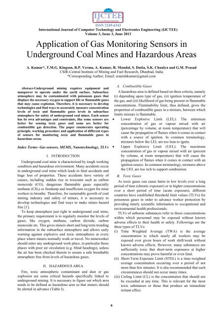
<strong>Application</strong> <strong>of</strong> <strong>Gas</strong> <strong>Monitor<strong>in</strong>g</strong> <strong>Sensors</strong> <strong>in</strong><br />
<strong>Underground</strong> <strong>Coal</strong> M<strong>in</strong>es and Hazardous Areas<br />
A. Kumar*, T.M.G. K<strong>in</strong>gson, R.P. Verma, A. Kumar, R. Mandal, S. Dutta, S.K. Chaulya and G.M. Prasad<br />
CSIR-Central Institute <strong>of</strong> M<strong>in</strong><strong>in</strong>g and Fuel Research, Dhanbad, India<br />
*Correspond<strong>in</strong>g Author, Email: eranishkumar@gmail.com<br />
Abstract-<strong>Underground</strong> m<strong>in</strong><strong>in</strong>g requires equipment and<br />
manpower to operate under the earth surface. Subsurface<br />
atmosphere may be contam<strong>in</strong>ated with poisonous gases that<br />
displace the necessary oxygen to support life or flammable gases<br />
that may cause explosion. Therefore, it is necessary to develop<br />
technologies and f<strong>in</strong>d ways to accurately measure concentration<br />
levels <strong>of</strong> toxic and flammable gases levels <strong>in</strong> subsurface<br />
atmosphere for safety <strong>of</strong> underground coal m<strong>in</strong>es. Each sensor<br />
has its own advantages and constra<strong>in</strong>ts, like some sensors are<br />
better for sens<strong>in</strong>g toxic gases and some are better for<br />
combustible gas detection. The paper enumerates operat<strong>in</strong>g<br />
pr<strong>in</strong>ciple, work<strong>in</strong>g procedure and application <strong>of</strong> different types<br />
<strong>of</strong> sensors for monitor<strong>in</strong>g toxic and flammable gases <strong>in</strong><br />
hazardous areas.<br />
Index Terms- <strong>Gas</strong> sensors, MEMS, Nanotechnology, TLVs<br />
I. INTRODUCTION<br />
<strong>Underground</strong> coal m<strong>in</strong>e is characterized by tough work<strong>in</strong>g<br />
condition and hazardous environment. Many accidents occur<br />
<strong>in</strong> underground coal m<strong>in</strong>e which leads to fatal accidents and<br />
huge loss <strong>of</strong> properties. These accidents have variety <strong>of</strong><br />
causes, <strong>in</strong>clud<strong>in</strong>g sudden rise <strong>in</strong> toxicants such as carbon<br />
monoxide (CO), dangerous flammable gases especially<br />
methane (CH 4 ) or firedamp and <strong>in</strong>sufficient oxygen for m<strong>in</strong>e<br />
workers to breathe. Therefore, for susta<strong>in</strong>able growth <strong>of</strong> coal<br />
m<strong>in</strong><strong>in</strong>g <strong>in</strong>dustry and safety <strong>of</strong> m<strong>in</strong>ers, it is necessary to<br />
develop technologies and f<strong>in</strong>d ways to make m<strong>in</strong>es hazard<br />
free [1].<br />
To keep atmosphere just right <strong>in</strong> underground coal m<strong>in</strong>e,<br />
the primary requirement is to regularly monitor the levels <strong>of</strong><br />
gases, like oxygen, methane, carbon dioxide, carbon<br />
monoxide etc. This gives m<strong>in</strong>ers short and long term trend<strong>in</strong>g<br />
<strong>in</strong>formation <strong>in</strong> the subsurface atmosphere and allows early<br />
warn<strong>in</strong>g aga<strong>in</strong>st explosive and toxic atmospheres at every<br />
place where m<strong>in</strong>ers normally work or travel. No m<strong>in</strong>eworker<br />
should enter any underground work place, <strong>in</strong> particular those<br />
places with poor air circulation (e.g. bl<strong>in</strong>d head<strong>in</strong>gs), unless<br />
the air has been checked there<strong>in</strong> to ensure a safe breathable<br />
atmosphere free from levels <strong>of</strong> hazardous gases.<br />
II. HAZARDOUS AREA<br />
Fire, toxic atmospheric contam<strong>in</strong>ant and dust or gas<br />
explosion are some critical hazards specifically l<strong>in</strong>ked to<br />
underground m<strong>in</strong><strong>in</strong>g. It is necessary to figure out which area<br />
needs to be def<strong>in</strong>ed as hazardous area so that m<strong>in</strong>ers should<br />
be alerted <strong>in</strong> advance (Table I).<br />
A. Combustible <strong>Gas</strong>es<br />
A hazardous area is def<strong>in</strong>ed based on three criteria, namely<br />
(i) depend<strong>in</strong>g upon type <strong>of</strong> gas, (ii) ignition temperature <strong>of</strong><br />
the gas, and (iii) likelihood <strong>of</strong> gas be<strong>in</strong>g present <strong>in</strong> flammable<br />
concentrations. Flammability limit, thus def<strong>in</strong>ed, gives the<br />
proportion <strong>of</strong> combustible gases <strong>in</strong> a mixture, between which<br />
limits mixture is flammable.<br />
Lower Explosive Limit (LEL): The m<strong>in</strong>imum<br />
concentration <strong>of</strong> gas or vapour mixed with air<br />
(percentage by volume, at room temperature) that will<br />
cause the propagation <strong>of</strong> flames when it comes <strong>in</strong> contact<br />
with a source <strong>of</strong> ignition. In common term<strong>in</strong>ology,<br />
mixtures below the LEL are too lean to ignite.<br />
Upper Explosive Limit (UEL): The maximum<br />
concentration <strong>of</strong> gas or vapour mixed with air (percent<br />
by volume, at room temperature) that will cause the<br />
propagation <strong>of</strong> flames when it comes <strong>in</strong> contact with an<br />
ignition source. In common term<strong>in</strong>ology, mixtures above<br />
the UEL are too rich to support combustion.<br />
B. Toxic <strong>Gas</strong>es<br />
As toxic gases can cause harm <strong>in</strong> low levels over a long<br />
period <strong>of</strong> time (chronic exposure) or <strong>in</strong> higher concentrations<br />
over a short period <strong>of</strong> time (acute exposure), different<br />
countries have established threshold limit values (TLVs) for<br />
poisonous gases <strong>in</strong> order to advance worker protection by<br />
provid<strong>in</strong>g timely scientific <strong>in</strong>formation to occupational and<br />
environmental health pr<strong>of</strong>essionals.<br />
TLVs <strong>of</strong> airborne substances refer to those concentrations<br />
with<strong>in</strong> which personnel may be exposed without known<br />
adverse effects to their health or safety. Follow<strong>in</strong>gs are the<br />
three types <strong>of</strong> TLVs:<br />
(i) Time Weighted Average (TWA) is the average<br />
concentration to which nearly all workers may be<br />
exposed over given hours <strong>of</strong> work shift/week without<br />
known adverse effects. However, many substances are<br />
sufficiently toxic that short-term exposures at higher<br />
concentrations may prove harmful or even fatal.<br />
(ii) Short-Term Exposure Limit (STEL) is a time-weighted<br />
average concentration occurr<strong>in</strong>g over a period <strong>of</strong> not<br />
more than few m<strong>in</strong>utes. It is also recommended that such<br />
circumstances should not occur many times.<br />
(iii) Ceil<strong>in</strong>g Limit (CL) is the concentration that should not<br />
be exceeded at any time. This is relevant for the most<br />
toxic substances or those that produce an immediate<br />
irritant effect.<br />
9
ISSN 2249-6343<br />
International Journal <strong>of</strong> Computer Technology and Electronics Eng<strong>in</strong>eer<strong>in</strong>g (IJCTEE)<br />
Volume 3, Issue 3, June 2013<br />
III. GAS DETECTING SENSORS<br />
<strong>Gas</strong> sensors detect presence <strong>of</strong> various gases with<strong>in</strong> an<br />
area, usually as a part <strong>of</strong> safety system. <strong>Sensors</strong> give a<br />
proportional electrical response depend<strong>in</strong>g upon the<br />
concentration <strong>of</strong> gas to be detected. If the concentration<br />
exceeds threshold concentration limit, the <strong>in</strong>strument<br />
conta<strong>in</strong><strong>in</strong>g it will provide an alarm to nearby personnel, or it<br />
may activate other remedial actions, such as <strong>in</strong>creas<strong>in</strong>g the<br />
ventilation, switch<strong>in</strong>g <strong>of</strong>f the power supply etc. [3]. Different<br />
methods for detect<strong>in</strong>g above gases are given <strong>in</strong> Table II and<br />
their operat<strong>in</strong>g pr<strong>in</strong>ciples are summarized <strong>in</strong> Table III.<br />
Table II: Different methods <strong>of</strong> gas detection [4]<br />
Name<br />
Methods <strong>of</strong> detection<br />
Oxygen<br />
Electrochemical, paramagnetic, flame<br />
lamp<br />
Methane<br />
Catalytic oxidation, thermal<br />
conductivity, optical, acoustic, flame<br />
lamp<br />
Carbon dioxide Optical, <strong>in</strong>frared<br />
Carbon monoxide Electrochemical, catalytic oxidation,<br />
semiconductor, <strong>in</strong>fra-red<br />
Sulphur dioxide Electrochemical, <strong>in</strong>fra-red<br />
Nitric oxide, Electrochemical<br />
Nitrous oxide,<br />
Nitrogen dioxide<br />
Hydrogen Electrochemical, semiconductor<br />
sulphide<br />
Hydrogen Catalytic oxidation<br />
A. Catalytic Bead <strong>Sensors</strong><br />
Theory: Combustible gas mixtures will not burn until they<br />
reach an ignition temperature. However, <strong>in</strong> the presence <strong>of</strong><br />
certa<strong>in</strong> chemical media, the gas will start to burn or ignite at<br />
lower temperatures. This phenomenon is known as a catalytic<br />
combustion.<br />
A coil <strong>of</strong> wire is coated with glass or ceramic material<br />
which is coated with a catalyst. The coil is electrically heated<br />
to a temperature that will allow it to burn (catalyze)<br />
combustible hydrocarbon (CHC) gas be<strong>in</strong>g monitored.<br />
Pellistors are m<strong>in</strong>iature calorimeters used to measure the<br />
energy liberated by burn<strong>in</strong>g <strong>of</strong> a combustible (flammable)<br />
gas or vapor [6]. A pellistor consists <strong>of</strong> a coil <strong>of</strong><br />
small-diameter plat<strong>in</strong>um wire supported <strong>in</strong> a refractory bead<br />
coated with a layer <strong>of</strong> catalytic material (Fig. 1), on which the<br />
gas is burnt. The coil serves two purposes: firstly, it is used to<br />
heat the bead electrically to its operat<strong>in</strong>g temperature <strong>of</strong><br />
around 500°C, and secondly it is used to detect changes <strong>in</strong><br />
temperature produced by oxidation <strong>of</strong> flammable gas.<br />
Work<strong>in</strong>g procedure: A Catalytic bead sensor is used <strong>in</strong><br />
Wheatstone bridge (Fig. 2), a circuit for measur<strong>in</strong>g an<br />
unknown resistance by compar<strong>in</strong>g it with known resistances.<br />
A balanced bridge has no output signal. R 1 is trim resistor that<br />
keeps the bridge balanced.<br />
Resistor value R B and trim pot R 1 are selected with<br />
relatively large resistance values to ensure proper function <strong>of</strong><br />
the circuit. Dur<strong>in</strong>g its operation, a current is passed through<br />
the coil, which heats up the bead to a high temperature. The<br />
gas is burned when a flammable gas molecule comes <strong>in</strong>to<br />
contact with the catalyst layer. The reaction occurs without a<br />
flame s<strong>in</strong>ce the level is below the Lower Explosive Limit (or<br />
LEL) <strong>of</strong> the gas. However, dur<strong>in</strong>g burn<strong>in</strong>g reaction, heat is<br />
released which <strong>in</strong>creases the temperature <strong>of</strong> bead. This<br />
<strong>in</strong>crease <strong>in</strong> temperature causes rise <strong>in</strong> electrical resistance <strong>of</strong><br />
the coil.<br />
Fig.1: Catalytic bead [7]<br />
There is another bead <strong>in</strong> the circuit which is identical to the<br />
detector bead, but does not conta<strong>in</strong> any catalyst. This bead<br />
will react to changes <strong>in</strong> humidity, ambient temperature etc.,<br />
but will not react to flammable gas. All that is required is a<br />
comparison <strong>of</strong> the resistance <strong>of</strong> one bead aga<strong>in</strong>st another <strong>in</strong> a<br />
Wheatstone bridge type circuit <strong>in</strong> order to obta<strong>in</strong> a<br />
mean<strong>in</strong>gful signal.<br />
Fig. 2: A catalytic bead sensor Wheatstone bridge [8]<br />
Reaction: Reaction takes place on the surface <strong>of</strong> catalytic<br />
bead is given as<br />
CH 4 + 2O 2 + 8N 2 CO 2 + 2H 2 O + 8N 2 (1)<br />
From the above reaction, one part <strong>of</strong> methane requires ten<br />
parts <strong>of</strong> air for complete combustion. For a sensor to detect<br />
methane, the signal output will respond l<strong>in</strong>early from 0–5%<br />
<strong>of</strong> methane. As the concentration reaches close to 9%, the<br />
signal <strong>in</strong>creases very rapidly & peaks at around 10% (Fig. 3).<br />
10
ISSN 2249-6343<br />
International Journal <strong>of</strong> Computer Technology and Electronics Eng<strong>in</strong>eer<strong>in</strong>g (IJCTEE)<br />
Volume 3, Issue 3, June 2013<br />
The signal starts to drop slowly as the concentration <strong>of</strong> gas<br />
passes approximately 20%; after 20% it drops sharply and at<br />
100% sensor signal is zero.<br />
follows:<br />
(i) Catalyst poison<strong>in</strong>g: Poison<strong>in</strong>g compounds cause a<br />
permanent reduction <strong>of</strong> the sensor sensitivity. The exact<br />
cause <strong>of</strong> poison<strong>in</strong>g is very difficult to identify. Tetraethyl<br />
lead, silicon compounds and sulphur compounds are<br />
among the most common poisons.<br />
(ii) Sensor <strong>in</strong>hibitors: Inhibitors cause a temporary loss <strong>of</strong><br />
sensitivity to sensor and may be partially or totally<br />
recovered after a short exposure to fresh air. The most<br />
common <strong>in</strong>hibitors are H 2 S, chlor<strong>in</strong>e, chlor<strong>in</strong>ated<br />
hydrocarbons and halogen compounds.<br />
(iii) Sensor crack<strong>in</strong>g: The sensor, when exposed to high<br />
concentration <strong>of</strong> gases, excessive heat and various<br />
oxidation processes that take place on the sensor surface,<br />
may eventually deteriorate its performance.<br />
Fig. 3: Sensor output vs. methane concentration [8]<br />
Factors affect<strong>in</strong>g the operations <strong>of</strong> catalytic sensors are as<br />
Factors affect<strong>in</strong>g the operations <strong>of</strong> catalytic sensors are as<br />
Table I: List <strong>of</strong> gases and their hazardous limits <strong>in</strong> underground m<strong>in</strong>es [2]<br />
Name <strong>of</strong> gas Flammability Guidel<strong>in</strong>e for TLVs<br />
Hazards<br />
limits <strong>in</strong> air (%)<br />
Oxygen >19.5% Oxygen deficiency, may cause<br />
explosive mixtures with reactive gases<br />
Nitrogen CL = 81,000 ppm Inert<br />
Methane 5 to15 At 1% isolate electricity, at 2% Explosion<br />
remove personnel.<br />
Carbon dioxide TWA = 0.5%, STEL = 3.0%, CL = Promotes <strong>in</strong>creased rate <strong>of</strong> respiration<br />
1.5%<br />
Carbon monoxide 12.5 to 74.5 TWA = 0.005%, STEL = 0.04%, Highly toxic; explosive<br />
CL = 200 ppm<br />
Sulphur dioxide<br />
TWA = 2 ppm, STEL = 5 ppm, CL<br />
= 10 ppm<br />
Very toxic; irritant to eyes throat and<br />
lungs<br />
Nitric oxide TWA = 50 ppm Oxidizes rapidly to NO 2<br />
Nitrous oxide TWA = 50 ppm Narcotic (laugh<strong>in</strong>g gas)<br />
Nitrogen dioxide TWA =3 ppm, CL= 5 ppm Very toxic; throat and lung irritant;<br />
pulmonary <strong>in</strong>fections<br />
Hydrogen sulphide 4.3 to 45.5 TWA = 10 ppm, STEL = 15ppm,<br />
CL = 15ppm<br />
Highly toxic; irritant to eyes and<br />
respiratory tracts; explosive<br />
Hydrogen 4 to 74.2 Highly explosive<br />
Table III: Classification <strong>of</strong> sensors by transducer operat<strong>in</strong>g pr<strong>in</strong>ciple [5]<br />
Sl.<br />
No.<br />
Types <strong>of</strong> devices Physical change Source <strong>of</strong> signal<br />
1 Catalytic gas sensors<br />
(pellistors), thermal<br />
sensors<br />
2 Optical sensors<br />
(<strong>in</strong>frared, laser, optical<br />
fiber)<br />
Temperature or<br />
heat<br />
Absorbance<br />
Lum<strong>in</strong>escence<br />
Refractive <strong>in</strong>dex<br />
Scatter<strong>in</strong>g<br />
Changes <strong>in</strong> resistance <strong>in</strong> wheat stone bridge<br />
3 Semiconductor (solid Electrical Changes <strong>in</strong> work function<br />
Either caused by gas itself, or due to reaction with certa<strong>in</strong> <strong>in</strong>dicator.<br />
Emission, caused by chemical reaction<br />
For example, caused by change <strong>in</strong> solution composition.<br />
Caused by particles <strong>of</strong> def<strong>in</strong>ite sizes present <strong>in</strong> the sample.<br />
11
ISSN 2249-6343<br />
International Journal <strong>of</strong> Computer Technology and Electronics Eng<strong>in</strong>eer<strong>in</strong>g (IJCTEE)<br />
Volume 3, Issue 3, June 2013<br />
state) gas sensors<br />
4 Electrochemical gas<br />
sensors<br />
(potentiometric or<br />
amperometric )<br />
5 Piezo-electric sensors<br />
(quartz crystal<br />
microbalance)<br />
6 Flame ionization<br />
detector, photo<br />
ionization detector<br />
B. Infrared <strong>Gas</strong> Sensor<br />
conductivity<br />
Voltametric<br />
Mass<br />
Ionisation<br />
Theory: <strong>Gas</strong> molecules are made up <strong>of</strong> number <strong>of</strong> atoms<br />
bonded to one another. These <strong>in</strong>teratomic bonds are similar to<br />
spr<strong>in</strong>gs, connect<strong>in</strong>g atoms <strong>of</strong> various masses together. This<br />
bond<strong>in</strong>g vibrates with a fixed frequency called the natural<br />
frequency. When <strong>in</strong>frared radiation <strong>in</strong>teracts with gas<br />
molecules as shown <strong>in</strong> Fig. 4, part <strong>of</strong> energy has the same<br />
frequency as the gas molecule‟s natural frequency and it is<br />
absorbed while rest <strong>of</strong> the radiation is transmitted. As the gas<br />
molecules absorb this radiation, the molecules ga<strong>in</strong> energy<br />
and vibrate more vigorously.<br />
Fig. 4: Effect <strong>of</strong> <strong>in</strong>frared radiation on bond<strong>in</strong>g <strong>of</strong> molecule<br />
This vibration results <strong>in</strong> temperature rise <strong>of</strong> gas molecules.<br />
Rise <strong>in</strong> temperature is detected by the detector. On the other<br />
hand, the radiation absorbed by the gas molecules at the<br />
particular wavelength will cause a decrease <strong>in</strong> the orig<strong>in</strong>al<br />
wavelength. This radiation energy decrease can be detected<br />
as a signal also.<br />
Work<strong>in</strong>g <strong>of</strong> Non-Dispersive Infrared (NDIR): It is based<br />
on <strong>in</strong>frared absorption property <strong>of</strong> some gases which consists<br />
<strong>of</strong> a s<strong>in</strong>gle IR source, a beam splitter and two detectors as<br />
shown <strong>in</strong> Fig. 5. One detector is used to monitor the<br />
characteristic hydrocarbon wavelength. The other is a<br />
reference that monitors an atmospheric “w<strong>in</strong>dow” where no<br />
IR active gases are normally present. Infrared energy<br />
(2-5microns, where micron is a common unit to express<br />
wavelength <strong>in</strong> <strong>in</strong>frared range) is emitted from the source,<br />
passes through the gas cell, and is reflected back to the<br />
detectors. If no hydrocarbons are present with<strong>in</strong> the gas<br />
sample, then energy reach<strong>in</strong>g the detector is the same.<br />
However, if some combustible hydrocarbons are present,<br />
they will absorb some IR energy at that wavelength, thus<br />
reduc<strong>in</strong>g the amount received by the analytic detector. <strong>Gas</strong><br />
concentration is determ<strong>in</strong>ed by compar<strong>in</strong>g the relative values<br />
between the two wavelengths (Fig. 6). This is called dual<br />
beam <strong>in</strong>frared detector [9]-[10].<br />
Changes <strong>in</strong> current between electrodes is measured<br />
Changes <strong>of</strong> resonant frequency <strong>of</strong> quartz oscillator plate due to<br />
adsorption <strong>of</strong> a gas on its chemically modified surface<br />
Amount <strong>of</strong> ionization<br />
Fig. 5: Infrared gas sensor [11]<br />
It is well known that almost all CHCs absorb IR at<br />
approximately 3.4 μm wave length, and at this region H 2 O<br />
and CO 2 are not absorbed, mak<strong>in</strong>g the system immune to<br />
humidity and atmospheric changes. Beer's Law describes the<br />
exact relationship between IR light <strong>in</strong>tensity and gas<br />
concentration [12]:<br />
I = I 0 e kP (2)<br />
Where:<br />
I — the <strong>in</strong>tensity <strong>of</strong> light strik<strong>in</strong>g the detector,<br />
I 0 — the measured <strong>in</strong>tensity <strong>of</strong> an empty sample chamber,<br />
k — a system dependent constant, and<br />
P — the concentration <strong>of</strong> the gas to be measured.<br />
Fig. 6: Spectral absorbance by gases [13]<br />
Infrared detectors convert electromagnetic radiation<br />
energy or temperature changes <strong>in</strong>to electrical signals. Some<br />
<strong>of</strong> the detectors (Fig. 7) types are:<br />
(i) Pyroelectric detector: Pyroelectric materials are crystals,<br />
such as lithium tantalite [14], which exhibit spontaneous<br />
polarization, or a concentrated electric charge that is<br />
temperature dependent. As <strong>in</strong>frared radiation strikes the<br />
detector surface, the change <strong>in</strong> temperature causes a<br />
current to flow. This current is proportional to the<br />
<strong>in</strong>tensity <strong>of</strong> radiation.<br />
12
ISSN 2249-6343<br />
International Journal <strong>of</strong> Computer Technology and Electronics Eng<strong>in</strong>eer<strong>in</strong>g (IJCTEE)<br />
Volume 3, Issue 3, June 2013<br />
This detector exhibits good sensitivity and good<br />
response to a wide range <strong>of</strong> wavelengths, and does not<br />
require cool<strong>in</strong>g <strong>of</strong> the detector. It is the most commonly<br />
used detector for gas monitors.<br />
(a)<br />
(b)<br />
to seal the chambers and the same <strong>in</strong>tensity <strong>of</strong> pulsed<br />
<strong>in</strong>frared radiation is received by both chambers when no<br />
target gas is present. When a sample conta<strong>in</strong><strong>in</strong>g target<br />
gas flows through the sample cell, reduced radiation<br />
energy is received by the detector chamber. This causes<br />
temperature and pressure to drop <strong>in</strong> the detector<br />
chamber. The amount <strong>of</strong> temperature or pressure drop is<br />
<strong>in</strong> direct proportion to the gas concentration. In the case<br />
<strong>of</strong> l<strong>in</strong>ked chambers, the pressure difference between the<br />
two chambers causes a detectable flow, which is<br />
measured as a signal. In the case where a diaphragm<br />
separates the two chambers, a movement <strong>of</strong> the<br />
diaphragm causes a measurable change <strong>in</strong> capacitance.<br />
(iii) Photoacoustic detector: This detector is similar to luft<br />
detector except that the pressure change is measured by a<br />
condenser microphone. The sample gas is passed<br />
through a chamber at a preset time <strong>in</strong>terval and the<br />
chamber is sealed with a fixed volume <strong>of</strong> sample gas<br />
trapped <strong>in</strong>side. A specific wavelength <strong>of</strong> <strong>in</strong>frared<br />
radiation is pulsed <strong>in</strong>to the chamber via an <strong>in</strong>frared<br />
transparent w<strong>in</strong>dow. The pulsat<strong>in</strong>g pressure change is<br />
measured by the microphone as a frequency change<br />
which produces the signal [16]-[17].<br />
Fourier Transform Infrared (FTIR): FTIR measur<strong>in</strong>g<br />
pr<strong>in</strong>ciple is used for multi-gas detection (Figs. 8). The<br />
pr<strong>in</strong>ciple <strong>of</strong> FTIR is that the gas to be analyzed is led through<br />
a cuvette with an IR light source at one end (i.e. send<strong>in</strong>g out<br />
scattered IR light), and a modulator that “cuts” the <strong>in</strong>frared<br />
light <strong>in</strong>to different wavelength. At other end <strong>of</strong> the cuvette, a<br />
detector is measur<strong>in</strong>g the amount <strong>of</strong> IR light to pass through<br />
the cuvette. By data process<strong>in</strong>g, Fourier Transformation<br />
mathematics is used to turn the measured absorption values<br />
<strong>in</strong>to gas concentration for the analyzed gases. As the light is<br />
modulated <strong>in</strong>to many different wavelengths, it is possible to<br />
analyze many different gases <strong>in</strong> the same <strong>in</strong>strument, such as<br />
CO, H 2 O, SO 2 , NO, HF, NH 3 etc. [18].<br />
(ii)<br />
(c)<br />
Fig. 7: Different detectors used for convert<strong>in</strong>g <strong>in</strong>to<br />
electrical signals: (a) Pyroelectric, (b) Luft and (c)<br />
Photoacoustic detector [13]<br />
Luft detector: A luft detector consists <strong>of</strong> two chambers,<br />
either l<strong>in</strong>ked by a micro flow sensor or divided by a<br />
diaphragm [15]. The chambers are sealed with a target<br />
gas at a low pressure. IR transparent w<strong>in</strong>dows are fitted<br />
Fig. 8: FTIR <strong>in</strong>frared spectrum [19]<br />
Infrared provides high accuracy, resistance to<br />
contam<strong>in</strong>ation and reliable measurements. Unlike catalytic<br />
bead sensor, gas sample enters and leaves the cell unchanged.<br />
Noth<strong>in</strong>g is transformed, substituted or removed from it. As<br />
the IR source ages, its energy level decreases. But there is<br />
only one source. Therefore, the energy level reduction will<br />
equally affect both sensor tubes (reference and detection) and<br />
no imbalance is detected.<br />
13
ISSN 2249-6343<br />
International Journal <strong>of</strong> Computer Technology and Electronics Eng<strong>in</strong>eer<strong>in</strong>g (IJCTEE)<br />
Volume 3, Issue 3, June 2013<br />
There is no need <strong>of</strong> extreme temperature for detection,<br />
result<strong>in</strong>g <strong>in</strong> less stress on construction materials. As there is<br />
no combustion, corrosive combustion by-products are not<br />
produced. All electronics and active components are sealed<br />
away from the combustible gas environment. So, there is no<br />
<strong>in</strong>hibitor, which helps <strong>in</strong> provid<strong>in</strong>g improved gas response<br />
[20].<br />
However, close coupl<strong>in</strong>g <strong>of</strong> electronics to IR sensor limits<br />
operation at high temperature. Exceed<strong>in</strong>g the operational<br />
temperature limit can cause IR sensor drift or failure. Due to<br />
component precision and assembly, IR sensors have higher<br />
<strong>in</strong>itial cost than catalytic detectors. IR sensors do not detect<br />
all combustible gases (e.g. hydrogen). Humidity and water<br />
may affect the sensor. Dust and dirt can coat the optics and<br />
impair sensor response.<br />
C. Electrochemical <strong>Sensors</strong><br />
Theory: Electrochemical sensors are fuel cell-like devices<br />
consist<strong>in</strong>g <strong>of</strong> an anode, cathode, and electrolyte. The<br />
components <strong>of</strong> the cell are selected such that target gas is<br />
allowed to diffuse <strong>in</strong>to the cell, which causes chemical<br />
reactions and generates current.<br />
Work<strong>in</strong>g procedure: It (Fig. 9) consists <strong>of</strong> a sens<strong>in</strong>g<br />
electrode (or work<strong>in</strong>g electrode) and counter electrode<br />
separated by a th<strong>in</strong> layer <strong>of</strong> electrolyte/catalysts. <strong>Gas</strong> that<br />
comes <strong>in</strong> contact with the sensor first passes through a small<br />
capillary-type open<strong>in</strong>g and then diffuses through a<br />
hydrophobic barrier, and eventually reaches the electrode<br />
surface. This approach is adopted to allow the proper amount<br />
<strong>of</strong> gas to react at the sens<strong>in</strong>g electrode to produce sufficient<br />
electrical signal while prevent<strong>in</strong>g the electrolyte leak<strong>in</strong>g out<br />
<strong>of</strong> the sensor. The gas that diffuses through the barrier reacts<br />
at the surface <strong>of</strong> the sens<strong>in</strong>g electrode <strong>in</strong>volv<strong>in</strong>g either an<br />
oxidation (CO, H 2 S, NO, SO 2 etc.) or reduction (NO 2 and<br />
Cl 2 ) mechanism. These reactions are catalyzed by electrode<br />
materials specifically developed for the gas <strong>of</strong> <strong>in</strong>terest [21].<br />
follow<strong>in</strong>g reactions:<br />
For work<strong>in</strong>g electrode: CO + H 2 O → CO 2 + 2H + + 2e - (3)<br />
For counter electrode: O 2 + 4H + + 4e - → 2H 2 O (4)<br />
Overall cell reaction: 2CO + O 2 → 2CO 2 (5)<br />
The ma<strong>in</strong> responsibility <strong>of</strong> the potentiostat circuit is to<br />
ensure that adequate current is fed to the counter electrode<br />
and the counter electrode can operate at its preferred<br />
potential.<br />
For a sensor requir<strong>in</strong>g an external driv<strong>in</strong>g voltage, the<br />
sens<strong>in</strong>g electrode potential does not rema<strong>in</strong> constant due to<br />
the cont<strong>in</strong>uous electrochemical reaction tak<strong>in</strong>g place on the<br />
surface <strong>of</strong> the electrode. It causes deterioration <strong>of</strong><br />
performance <strong>of</strong> the sensor over extended periods <strong>of</strong> time. To<br />
improve the performance <strong>of</strong> the sensor, a reference electrode<br />
is <strong>in</strong>troduced. The reference electrode ma<strong>in</strong>ta<strong>in</strong>s the value <strong>of</strong><br />
this fixed voltage at the sens<strong>in</strong>g electrode. No current flows to<br />
or from the reference electrode. Sometimes a scrubber filter<br />
is <strong>in</strong>stalled <strong>in</strong> front <strong>of</strong> the sensor to filter out unwanted gases.<br />
[23].<br />
<strong>Gas</strong> specific electrochemical sensors can be used to detect<br />
the majority <strong>of</strong> common toxic gases, namely CO, H 2 S, Cl 2 ,<br />
SO 2 etc. <strong>in</strong> a wide variety <strong>of</strong> safety applications. They can be<br />
specific to a particular gas or vapour. They are typically very<br />
accurate. They do not get poisoned easily.<br />
As disadvantages, electrochemical gas sensors have a<br />
narrow temperature range and a short shelf life; they are<br />
subject to several <strong>in</strong>terfer<strong>in</strong>g gases such as hydrogen. Sensor<br />
lifetime will be shortened <strong>in</strong> very dry and hot areas.<br />
D. Semiconductor Sensor<br />
Theory: These sensors (also called solid state sensor) are<br />
primarily used for toxic gas measurements and limited use <strong>in</strong><br />
CHC gas measurement. A semi conduct<strong>in</strong>g material is<br />
applied to a non-conduct<strong>in</strong>g substrate between two electrodes<br />
(Fig. 10).<br />
Fig. 9: Electrochemical gas sensor [22]<br />
The counter electrode balances the reaction <strong>of</strong> sens<strong>in</strong>g<br />
electrode – if the sens<strong>in</strong>g electrode oxidizes the gas, then the<br />
counter electrode must reduce some other molecule to<br />
generate an equivalent current.<br />
Reactions: The reaction k<strong>in</strong>ematics is expla<strong>in</strong>ed by the<br />
Fig. 10: Schematic diagram <strong>of</strong> modern resistive<br />
semiconductor gas sensor [24]<br />
The substrate is heated to a temperature such that the gas<br />
be<strong>in</strong>g monitored can cause a reversible change <strong>in</strong> the<br />
conductivity <strong>of</strong> the semi-conduct<strong>in</strong>g material. The target gas<br />
<strong>in</strong>teracts with the surface <strong>of</strong> the metal oxide film (generally<br />
through surface adsorbed oxygen ions), which results <strong>in</strong><br />
14
ISSN 2249-6343<br />
International Journal <strong>of</strong> Computer Technology and Electronics Eng<strong>in</strong>eer<strong>in</strong>g (IJCTEE)<br />
Volume 3, Issue 3, June 2013<br />
change <strong>in</strong> charge carrier concentration <strong>of</strong> the material.<br />
This leads to alter the conductivity <strong>of</strong> the material. An<br />
n-type semiconductor is one where the majority charge<br />
carriers are electrons, and upon <strong>in</strong>teraction with a reduc<strong>in</strong>g<br />
gas an <strong>in</strong>crease <strong>in</strong> conductivity occurs. Conversely, an<br />
oxidiz<strong>in</strong>g gas serves to deplete the sens<strong>in</strong>g layer <strong>of</strong> charge<br />
carry<strong>in</strong>g electrons, result<strong>in</strong>g <strong>in</strong> a decrease <strong>in</strong> conductivity.<br />
Opposite effects are observed with p-type semiconductor<br />
material (Table IV).<br />
T<strong>in</strong> oxide semiconductor is small, mechanically rugged,<br />
sensitive to parts per million (ppm) levels, flood-pro<strong>of</strong> and<br />
less expensive. The major disadvantage <strong>of</strong> the sensor is that<br />
the sensor is sensitive to humidity and temperature, but not<br />
specific to gases and vapors.<br />
Table IV: Response <strong>of</strong> semiconductor for different types<br />
<strong>of</strong> gases [25]<br />
Classification Oxidiz<strong>in</strong>g gases Reduc<strong>in</strong>g gases<br />
n-type<br />
p-type<br />
Resistance<br />
<strong>in</strong>crease<br />
Resistance<br />
decrease<br />
Resistance<br />
decrease<br />
Resistance<br />
<strong>in</strong>crease<br />
Work<strong>in</strong>g procedure: The gas sens<strong>in</strong>g film is located on a<br />
micro mach<strong>in</strong>ed hotplate which operates at 100-400 °C.<br />
Under zero gas condition, it is assumed that O 2 molecules tie<br />
up free electrons <strong>in</strong> the metal oxide semiconductor material<br />
by absorb<strong>in</strong>g on its surface, thereby <strong>in</strong>hibit<strong>in</strong>g electrical flow<br />
[26]. The depleted layers are responsible for a high contact<br />
resistance. For conduction, electrons must cross over the<br />
surface barriers.<br />
As reduc<strong>in</strong>g gases (CO, methane, H 2 S or H 2 gases) are<br />
<strong>in</strong>troduced, they replace the O 2 , release free electrons and<br />
decrease resistance between the electrodes (Fig. 11). This<br />
change <strong>in</strong> resistance is measured electrically. It is<br />
proportional to the concentration <strong>of</strong> gas be<strong>in</strong>g measured [28].<br />
The sensitivity <strong>of</strong> metal-oxide gas sensors can be<br />
substantially improved by dispers<strong>in</strong>g a low concentration <strong>of</strong><br />
additives, such as Pd, Pt, Au etc.<br />
Reactions: Atmospheric oxygen molecules are adsorbed<br />
on the surface <strong>of</strong> semiconductor oxides <strong>in</strong> the form <strong>of</strong> O − , O 2-<br />
or O 2 − . The reaction k<strong>in</strong>ematics is expla<strong>in</strong>ed by the follow<strong>in</strong>g<br />
reactions:<br />
O 2 (gas) + e − → O 2 (ads) − (6)<br />
O 2 (gas) − + e − → 2O (ads) − (7)<br />
The presence <strong>of</strong> chemically adsorbed oxygen causes<br />
electron depletion <strong>in</strong> the th<strong>in</strong> film surface and build<strong>in</strong>g up <strong>of</strong><br />
Schottky surface barrier. Consequently, the electrical<br />
conductance <strong>of</strong> th<strong>in</strong> film decreases to a m<strong>in</strong>imum. The SnO 2<br />
th<strong>in</strong> film <strong>in</strong>teracts with oxygen by transferr<strong>in</strong>g the electron<br />
from the conduction band to adsorb oxygen atoms. The<br />
response to H 2 S can be expla<strong>in</strong>ed as a reaction <strong>of</strong> gas with the<br />
O 2 (ads) − :<br />
H 2 S + 3O (ads) − → H 2 O(g) + SO 2 (g) + 3e − (8)<br />
With this reaction, many electrons are released to th<strong>in</strong> film<br />
surface. This decreases the Schottky surface barrier and<br />
makes depletion layer th<strong>in</strong>ner; consequently, the electrical<br />
conductance <strong>of</strong> the th<strong>in</strong> film <strong>in</strong>creases. Metal oxide<br />
semiconductor (MOS) sensors may be used for toxic as well<br />
as combustible gas monitor<strong>in</strong>g.<br />
Fig.11: Conductivity model <strong>of</strong> SnO 2 : (a) <strong>in</strong> air; (b) dur<strong>in</strong>g<br />
exposure to CO (Debye length lD
ISSN 2249-6343<br />
International Journal <strong>of</strong> Computer Technology and Electronics Eng<strong>in</strong>eer<strong>in</strong>g (IJCTEE)<br />
Volume 3, Issue 3, June 2013<br />
sensor.<br />
Work<strong>in</strong>g procedure: Most <strong>of</strong> gaseous materials show<br />
characteristic optical absorptions, especially <strong>in</strong> the<br />
mid-<strong>in</strong>frared (2–25µm) band. The optical f<strong>in</strong>gerpr<strong>in</strong>ts <strong>of</strong><br />
different gases have made the spectral absorption a unique<br />
method <strong>of</strong> gas analysis [31]. In TDLAS, a diode laser emits<br />
light at a well-def<strong>in</strong>ed but tunable wavelength over the<br />
characteristic absorption l<strong>in</strong>es <strong>of</strong> a target gas <strong>in</strong> the path <strong>of</strong> the<br />
laser beam. This causes a reduction <strong>of</strong> the measured signal<br />
<strong>in</strong>tensity, which can be detected by a photodiode, and then<br />
used to determ<strong>in</strong>e the gas concentration (Fig. 12).<br />
Fig. 12: TDLAS gas detector system [32]<br />
Different diode laser are used based on application and the<br />
range <strong>of</strong> tun<strong>in</strong>g required. Typical examples <strong>of</strong> laser diode are<br />
InGaAsP/ InP (tunable over 900 nm to 1.6 µm), InGaAsP/<br />
InAsP (tunable over 1.6 µm to 2.2 µm) [33]. Vary<strong>in</strong>g the<br />
quantum cascade laser (QCL) temperature and/or laser<br />
<strong>in</strong>jection current provides wavelength tun<strong>in</strong>g <strong>of</strong> the emitted<br />
laser radiation from DFB devices with<strong>in</strong> a limited spectral<br />
range (~10 cm-1). The external cavity configuration,<br />
EC-QCL approach allows tun<strong>in</strong>g over a range <strong>of</strong> >200 cm-1<br />
[34]. Wavelength modulation spectroscopy (WMS) is based<br />
on the modulation <strong>of</strong> the light emitted by a laser that is slowly<br />
tuned through an absorption feature <strong>of</strong> the species to be<br />
detected. The signal <strong>of</strong> second harmonic can be measured<br />
with lock-<strong>in</strong> amplifier and it is proportional to the<br />
concentration [35]. In different temperature conditions, for<br />
the same concentration <strong>of</strong> gas, the amplitude <strong>of</strong> second<br />
harmonic detected by lock <strong>in</strong> amplifier fluctuates with the<br />
variation <strong>of</strong> ambient temperature. WMS measures faster<br />
response and can provide parts per million (ppm) to parts per<br />
billion (ppb) chemical detection limits, depend<strong>in</strong>g on the<br />
spectroscopic properties <strong>of</strong> the target gas and the sampl<strong>in</strong>g<br />
path length. WMS is thus a highly sensitive and gas-specific<br />
form <strong>of</strong> spectroscopic gas analysis [32].<br />
Advantages:<br />
a. TDLAS has been widely employed <strong>in</strong> detect<strong>in</strong>g<br />
atmospheric trace gases due to its high sensitivity, high<br />
selectivity, and fast time.<br />
b. TDLAS method uses a compact s<strong>in</strong>gle mode diode laser<br />
tun<strong>in</strong>g over an <strong>in</strong>terested wavelength range swiftly to<br />
fulfill the function <strong>of</strong> spectroscopy scan, may overcome<br />
the drawback <strong>of</strong> FTIR, especially <strong>in</strong> field on-l<strong>in</strong>e<br />
applications where fast response needed [29].<br />
c. A further advantage <strong>of</strong> near <strong>in</strong>frared TDLAS is<br />
compatible with optical fibers for optical<br />
communication, which makes it easy to realize<br />
multipo<strong>in</strong>t remote sens<strong>in</strong>g.<br />
d. The laser emission l<strong>in</strong>e-width is narrower than gas<br />
absorption l<strong>in</strong>e-widths. This may be contrasted with<br />
near-IR (NIR) absorption techniques that sample with<br />
broadband sources and measure absorption from<br />
multiple l<strong>in</strong>es across a fairly broad range <strong>of</strong> frequencies.<br />
TDLAS thus <strong>of</strong>fers the advantage <strong>of</strong> selectivity for a<br />
target trace gas absent spectral <strong>in</strong>terferences from other<br />
background gases.<br />
Disadvantages:<br />
a. In different temperature conditions, for the same<br />
concentration <strong>of</strong> gas, the amplitude <strong>of</strong> second harmonic<br />
detected by lock <strong>in</strong> amplifier fluctuates with the variation<br />
<strong>of</strong> ambient temperature. For the retrieval <strong>of</strong> the trace gas<br />
concentration, the <strong>in</strong>fluence <strong>of</strong> temperature fluctuations<br />
must be taken <strong>in</strong>to account.<br />
b. Any noise <strong>in</strong>troduced by the light source or the optical<br />
system will deteriorate the detectability <strong>of</strong> the technique.<br />
2) Differential Absorption Light Detection and Rang<strong>in</strong>g<br />
Theory: Simple TDLAS measures the presence/<br />
concentration <strong>of</strong> a particular gas is based on receiver<br />
measur<strong>in</strong>g wavelength not absorbed by the target gas<br />
whereas differential absorption light detection and rang<strong>in</strong>g is<br />
based on return<strong>in</strong>g backscattered signal <strong>in</strong>tensity absorbed by<br />
target gas as shown <strong>in</strong> Fig. 13. This system can detect and<br />
measure the presence <strong>of</strong> CO 2 , CO, CH 4 etc. LIDAR (Light<br />
Detection And Rang<strong>in</strong>g) operates <strong>in</strong> the ultraviolet, visible<br />
and <strong>in</strong>frared portion <strong>of</strong> the spectrum [36].<br />
Fig. 13: Differential absorption LIDAR concept [36]<br />
Work<strong>in</strong>g procedure: The laser source emits a laser beam <strong>in</strong><br />
tune with molecular absorption l<strong>in</strong>e <strong>of</strong> a target gas and<br />
receives a reflected signal affected by gas absorption <strong>of</strong> the<br />
target gas <strong>in</strong> the atmosphere [37]. Near the optimum<br />
wavelength for the particular gas to be measured, the amount<br />
<strong>of</strong> absorption <strong>of</strong> the transmitted light varies strongly<br />
accord<strong>in</strong>g to the wavelength for each particular molecule, and<br />
this creates unique molecular “signatures” for these gases.<br />
Therefore, the method called “Differential Absorption<br />
LIDAR” (DIAL) can be used to determ<strong>in</strong>e the concentration.<br />
16
ISSN 2249-6343<br />
International Journal <strong>of</strong> Computer Technology and Electronics Eng<strong>in</strong>eer<strong>in</strong>g (IJCTEE)<br />
Volume 3, Issue 3, June 2013<br />
The large dust particles also backscatter radiation, but their<br />
scatter<strong>in</strong>g is much less wavelength dependent [38].<br />
F. Fiber Optic Sensor<br />
Theory: Two dist<strong>in</strong>ct approaches used <strong>in</strong> fiber optic<br />
sensors are: Firstly, by directly prob<strong>in</strong>g the spectrochemical<br />
changes, when <strong>in</strong>terrogat<strong>in</strong>g wavelength co<strong>in</strong>cides with the<br />
absorption band <strong>of</strong> the analyte. Such direct spectroscopic<br />
measurement is observed <strong>in</strong> near <strong>in</strong>frared TDLAS. Secondly,<br />
by utiliz<strong>in</strong>g an analyte specific reagent transducer converts<br />
analyte concentration <strong>in</strong>to an optical signal. Majority <strong>of</strong> this<br />
<strong>in</strong>volve an <strong>in</strong>termediate sensor element, which undergoes<br />
chemical changes <strong>in</strong>itiated <strong>in</strong> the presence <strong>of</strong> the specific<br />
analyte [39].<br />
In second method, sensor works based on modified<br />
cladd<strong>in</strong>g approach [40]. The cladd<strong>in</strong>g <strong>of</strong> the optical fiber is<br />
removed and the gas sensitive material (the conduct<strong>in</strong>g<br />
polymer film) is coated on a small section <strong>of</strong> the fiber<br />
(sens<strong>in</strong>g probe). The sens<strong>in</strong>g probe length, source <strong>in</strong>tensity<br />
and source wavelength, <strong>in</strong>dicates <strong>in</strong>fluence on the sensor<br />
response.<br />
Work<strong>in</strong>g procedure: Optical fiber sensor uses a light<br />
modulation, i.e. one <strong>of</strong> the light parameter changes accord<strong>in</strong>g<br />
to the analytes presence. Organic conduct<strong>in</strong>g polymer such as<br />
polypyrrole, polyanil<strong>in</strong>e, polythiophene shows a reversible<br />
change <strong>in</strong> their resistance when exposed to certa<strong>in</strong> vapors<br />
[41]. The change <strong>in</strong> conductivity changes permittivity, which<br />
leads to change <strong>in</strong> the refractive <strong>in</strong>dex. The analytes reacts<br />
with the coat<strong>in</strong>g to change the optical properties i.e. refractive<br />
<strong>in</strong>dex, absorbance, and fluorescence which is coupled to core<br />
to change the transmission properties through the optical<br />
fiber. An extr<strong>in</strong>sic fiber-optic evanescent wave chemical<br />
sensor is developed by replac<strong>in</strong>g a certa<strong>in</strong> portion <strong>of</strong> the<br />
orig<strong>in</strong>al cladd<strong>in</strong>g with chemically sensitive material [42].<br />
The sensor structure <strong>in</strong> which small section <strong>of</strong> cladd<strong>in</strong>g is<br />
replaced with chemically sensitive layer is shown <strong>in</strong> Fig. 14.<br />
Advantages <strong>of</strong> fiber optic sensor are geometrical<br />
flexibility, remote sens<strong>in</strong>g capability, small size and<br />
lightweight. It <strong>of</strong>fers complete electrical isolation.<br />
G. Thermal Conductivity<br />
The pr<strong>in</strong>ciple <strong>of</strong> thermal conductivity is very similar to that<br />
<strong>of</strong> the pellistor. Two plat<strong>in</strong>um coils are arranged <strong>in</strong> a<br />
Wheatstone bridge circuit. One coil is <strong>in</strong> contact with the gas<br />
stream and other is sealed <strong>in</strong>to a separate chamber, used for<br />
temperature compensation (Fig. 15). All the gases have<br />
different thermal conductivity‟s and so will conduct heat<br />
away from the coil <strong>in</strong> the gas stream at different rates. The<br />
change <strong>in</strong> temperature <strong>of</strong> the coil is directly proportional to<br />
the change <strong>in</strong> thermal conductivity <strong>of</strong> the gas mixture flow<strong>in</strong>g<br />
past it [43].<br />
The major drawback <strong>of</strong> the sensor is that it is less selective<br />
and sensitive. This technique for detect<strong>in</strong>g gas is suitable for<br />
the measurement <strong>of</strong> high (%V/V) concentrations <strong>of</strong> b<strong>in</strong>ary<br />
gas mixes<br />
Fig.15: Thermal conductivity [44]<br />
H. Ionization Detector<br />
Photo ionization (Fig. 16) and flame ionization (Fig. 17)<br />
are common detection techniques used for gas<br />
chromatographic (GC) systems <strong>in</strong> laboratory environments.<br />
Both have very good sensitivity and large l<strong>in</strong>ear dynamic<br />
range.<br />
Fig. 14: Configuration <strong>of</strong> fiber optic sensor and geometric<br />
optics ray through the sens<strong>in</strong>g region [42]<br />
Any change <strong>in</strong> the refractive <strong>in</strong>dex <strong>of</strong> the modified<br />
cladd<strong>in</strong>g due to the analyte can change the condition <strong>of</strong> total<br />
<strong>in</strong>ternal reflection between the modified cladd<strong>in</strong>g and air, and<br />
results <strong>in</strong> an <strong>in</strong>tensity change.<br />
Fig. 16: Photo ionization detector [47]<br />
Both techniques measure the current generated by the<br />
ionized species sensed by ion collector. The photoionization<br />
technique ionizes molecules us<strong>in</strong>g a high energy photon<br />
source, such as ultraviolet (UV) radiation [45], while flame<br />
17
ISSN 2249-6343<br />
International Journal <strong>of</strong> Computer Technology and Electronics Eng<strong>in</strong>eer<strong>in</strong>g (IJCTEE)<br />
Volume 3, Issue 3, June 2013<br />
ionization technique burns organic molecules <strong>in</strong> a hydrogen<br />
flame [46]. The ions generations are detected similarly <strong>in</strong><br />
both PIDs and FIDs. When electric field gradient is applied<br />
across the ionization region to drive the ions to the electrodes,<br />
the ions release their charges to produce signals that can be<br />
processed.<br />
Fig. 18: CMOS based micro hotplate design <strong>of</strong> gas sensor<br />
array [50]<br />
The resistance <strong>of</strong> a metal oxide film varies depend<strong>in</strong>g on<br />
the type <strong>of</strong> gas exposure. Combustible gases such as CH 4 ,<br />
H 2 S and NH 3 act as reduc<strong>in</strong>g agents thereby add<strong>in</strong>g electrons<br />
to the metal oxide, which <strong>in</strong>creases conductivity (decreases<br />
resistance). Metal oxide sens<strong>in</strong>g films have been doped with<br />
noble metals to <strong>in</strong>crease sensitivity and reduce response time.<br />
Dopants such as Pt or Pd are catalysts that promote chemical<br />
reactions by reduc<strong>in</strong>g the activation energy between the film<br />
and test gas without be<strong>in</strong>g consumed by them. This allows the<br />
reaction to occur at a faster rate and lower gas concentrations.<br />
Cantilever based sensor (piezoelectric based):<br />
Piezoelectric power generator made by MEMS technology<br />
can scavenge power from low-level ambient vibration<br />
sources. The developed MEMS power generators are<br />
featured with fixed/narrow operation frequency and power<br />
output <strong>in</strong> microwatt level [52]. These devices can be used as<br />
sens<strong>in</strong>g platforms. Molecular adsorption <strong>of</strong> target gas onto<br />
Fig. 17: Flame ionization detector [48]<br />
The ma<strong>in</strong> differences between these two techniques are<br />
their ionization source and mechanism. The photoionization<br />
technique is a nondestructive method whereas the gas sample<br />
is destroyed <strong>in</strong> flame ionization method.<br />
I. MEMS Technology<br />
Micro-electro-mechanical systems (MEMS) are<br />
three-dimensional, electro-mechanical devices, which are<br />
made by micromach<strong>in</strong><strong>in</strong>g silicon wafers us<strong>in</strong>g standard<br />
microelectronic fabrication and post-process techniques [49].<br />
MEMS have been used to reduce the size, power<br />
consumption and cost <strong>of</strong> gas sensors while improv<strong>in</strong>g overall<br />
performance [50]. MEMS can be used <strong>in</strong> different <strong>in</strong>novative<br />
ways by comb<strong>in</strong><strong>in</strong>g the exist<strong>in</strong>g proven technologies as<br />
described herewith.<br />
MEMS based array <strong>of</strong> sensor (work function based):<br />
Micromach<strong>in</strong><strong>in</strong>g processes have enabled designers to place<br />
arrays <strong>of</strong> sensors on a s<strong>in</strong>gle chip that can be mass-produced<br />
at reduced cost. SnO 2 /Pt, WO 3 /Au and ZnO/Pd sens<strong>in</strong>g films<br />
were found sensitive to the target gases NH 3 , H 2 S, and CH 4 ,<br />
respectively. Sens<strong>in</strong>g pastes are deposited on the outside <strong>of</strong> a<br />
ceramic tube with a heater on the <strong>in</strong>side (Fig. 18). But these<br />
sensors have some cross-sensitivity. Further, this technique<br />
suffers from basel<strong>in</strong>e drift, and high resistance and recovery<br />
time. However, sensor array response to the gases is unique,<br />
which allows selectivity by pattern recognition [51].<br />
Fig. 19: Cantilever based hydrogen gas sensor [54]<br />
the sens<strong>in</strong>g element, a cantilever, shifts its resonance<br />
frequency and changes its surface forces (surface stress).<br />
Adsorption onto the sens<strong>in</strong>g element (composed <strong>of</strong> two<br />
chemically different surfaces) produces a differential stress<br />
between the two surfaces and <strong>in</strong>duces bend<strong>in</strong>g. The analyte<br />
that <strong>in</strong>duces the mechanical response is chemisorbed onto the<br />
cantilever <strong>in</strong> a reversible or irreversible process. Devices that<br />
respond to chemical stimuli <strong>in</strong> this manner are referred as<br />
micro-cantilever sensors [53].<br />
Cantilever based hydrogen sensor uses piezoelectric<br />
pr<strong>in</strong>ciple for gas sens<strong>in</strong>g. This sensor uses stress-sensitive,<br />
palladium coated micro-cantilevers to detect hydrogen (Fig.<br />
19). Absorption <strong>of</strong> hydrogen <strong>in</strong>to palladium is fully<br />
reversible, at any given moment the cantilever capacitance<br />
<strong>in</strong>dicates the current hydrogen concentration [54].<br />
J. Nanotechnology<br />
<strong>Application</strong>s <strong>of</strong> nanotechnology <strong>in</strong> gas sensors are still <strong>in</strong><br />
the prelim<strong>in</strong>ary stage <strong>of</strong> development. Presently, metal oxide<br />
1-dimensional (1D) nanostructure as gas sensors are most<br />
promis<strong>in</strong>g area for nanotechnology. Some other 1D<br />
nanostructure gas sensors operation is based on changes <strong>in</strong><br />
the photolum<strong>in</strong>escence spectroscopy and the mass <strong>of</strong> sens<strong>in</strong>g<br />
18
ISSN 2249-6343<br />
International Journal <strong>of</strong> Computer Technology and Electronics Eng<strong>in</strong>eer<strong>in</strong>g (IJCTEE)<br />
Volume 3, Issue 3, June 2013<br />
element, which accurately uses a quartz crystal microbalance<br />
[55].<br />
1D nanostructure has advantages over conventional<br />
metal-oxide-based sensors <strong>in</strong> terms <strong>of</strong> power consumption,<br />
sensitivity, m<strong>in</strong>iaturization and large surface area to volume<br />
ratio [56]. The change <strong>in</strong> the electrical conductivity caused by<br />
chemisorption <strong>of</strong> gas molecules on the surface <strong>of</strong> 1D<br />
nanostructure metal oxides is measured by<br />
electro-transducers. The ma<strong>in</strong> structures <strong>of</strong> the<br />
electro-transducers are field effect transistors (FET), resistive<br />
gas micro-sensors, and resistive gas sensors [57]. 1D<br />
nanostructure FET is fabricated us<strong>in</strong>g a s<strong>in</strong>gle nanowire<br />
bridge between two metal electrodes on a heavily doped<br />
silicon substrate covered with SiO 2 act<strong>in</strong>g as <strong>in</strong>sulat<strong>in</strong>g layer<br />
between the nanowire/electrode comb<strong>in</strong>ations and the<br />
conduct<strong>in</strong>g silicon (Fig. 20).<br />
Fig. 20: The schematic <strong>of</strong> the s<strong>in</strong>gle nanowire FET [57]<br />
Resistive gas micro-sensors are manufactured by MEMS<br />
technology <strong>in</strong> which a film composed <strong>of</strong> nanowires is<br />
contacted by pairs <strong>of</strong> metal electrodes on a substrate (Fig.<br />
21). The measurement is performed by monitor<strong>in</strong>g the<br />
changes <strong>in</strong> current or resistance <strong>of</strong> the device. The other one<br />
is resistive gas sensor, the channel length between the two<br />
electrodes for resistive sensor is usually <strong>in</strong> the millimeter<br />
scale with<strong>in</strong> a ceramic tube.<br />
the sens<strong>in</strong>g material. It is quantitatively measured based on<br />
change <strong>in</strong> frequency rate (S f ) given by:<br />
S f = |∆f/∆t| = | (af 2 ∆m/A)/ ∆t | (9)<br />
Where,<br />
∆ƒ — response frequency shift with<strong>in</strong> the time <strong>in</strong>terval <strong>of</strong><br />
∆t,<br />
a — constant,<br />
ƒ— fundamental frequency <strong>of</strong> the unloaded piezoelectric<br />
crystal,<br />
∆m — mass load<strong>in</strong>g on the surface <strong>of</strong> the crystal, and<br />
A — surface area <strong>of</strong> the electrode.<br />
Ceramics such as z<strong>in</strong>c oxide (ZnO), t<strong>in</strong> oxide (SnO2),<br />
<strong>in</strong>dium oxide (In2O3), and titanium dioxide or titania (TiO2)<br />
are used as nanowires/nanobelts for gas sens<strong>in</strong>g. Carbon<br />
nanotubes (CNTs) have many dist<strong>in</strong>ct properties that may be<br />
exploited to develop next generation sensors. S<strong>in</strong>gle walled<br />
nanotubes (SWNTs) have been highlighted as gas-sens<strong>in</strong>g<br />
elements due to the 1D structure with all the atoms resid<strong>in</strong>g<br />
only on the surface.<br />
CNTs can be designed to have specific properties by<br />
chang<strong>in</strong>g the ratio <strong>of</strong> diameters <strong>of</strong> l<strong>in</strong>early jo<strong>in</strong>ed CNTs,<br />
which <strong>in</strong> turn can be used <strong>in</strong> fabrication <strong>of</strong> FETs. The<br />
untreated SWNT-FET typically shows a p-type behavior,<br />
with threshold voltages be<strong>in</strong>g shifted upon gas exposure [58].<br />
The <strong>in</strong>let and outlet valves allow gases to flow over the<br />
carbon nanotubes <strong>of</strong> FET. <strong>Gas</strong> flow <strong>in</strong>creases conductance <strong>of</strong><br />
the carbon nanotubes. This can be obta<strong>in</strong>ed us<strong>in</strong>g<br />
current-voltage relationship before and after exposure to the<br />
gases. The effect occurs because when the gas molecules<br />
bond to the carbon nanotubes, charge is transferred from the<br />
nanotubes to the gas molecules, which <strong>in</strong>creases<br />
hole-concentration <strong>in</strong> the carbon nanotubes and enhances the<br />
conductance (Fig. 22). The carbon nanotubes are covered<br />
with an <strong>in</strong>sulat<strong>in</strong>g protection film [59]. CNTs show almost<br />
threefold sensitivity and efficiency compare to other metal<br />
oxide gas sensors available <strong>in</strong> the market, such as t<strong>in</strong> oxide<br />
sensor [60].<br />
Fig. 21: Resistive nano-sensors: (a) MEMS structures with<br />
<strong>in</strong>terdigitated electrode; and (b) nanowire gas sensors on<br />
ceramic tube [57].<br />
For photolum<strong>in</strong>escence measurement, nanowire samples<br />
are mounted <strong>in</strong> a small vacuum chamber with ports to pass<br />
gasses and provide optical access. Photo-desorption and<br />
photo-adsorption <strong>of</strong> gases are found to affect the <strong>in</strong>tensity,<br />
<strong>in</strong>dicat<strong>in</strong>g the participation <strong>of</strong> free carriers. The time<br />
dependence <strong>of</strong> the changes <strong>in</strong> the spectral peak <strong>in</strong>tensity is<br />
compared for measurement <strong>of</strong> gas concentration.<br />
Quartz crystal microbalance (QCM) is an extremely<br />
sensitive measurement device. The pr<strong>in</strong>ciple <strong>of</strong> measurement<br />
is based on mass change as the gas adsorbs on the surface <strong>of</strong><br />
Fig. 22: Carbon nanotubes based gas sensor us<strong>in</strong>g MEMS<br />
platform [61]<br />
IV. CHARACTERISTICS OF GAS SENSORS<br />
Performance <strong>of</strong> sensors is characterized by the follow<strong>in</strong>g<br />
parameters [62]:<br />
Sensitivity is a change <strong>of</strong> measured signal per analyte<br />
concentration unit, i.e. the slope <strong>of</strong> a calibration graph.<br />
19
ISSN 2249-6343<br />
International Journal <strong>of</strong> Computer Technology and Electronics Eng<strong>in</strong>eer<strong>in</strong>g (IJCTEE)<br />
Volume 3, Issue 3, June 2013<br />
<br />
<br />
<br />
<br />
<br />
<br />
<br />
<br />
<br />
<br />
This parameter is sometimes confused with the detection<br />
limit.<br />
Selectivity refers to characteristic that determ<strong>in</strong>es<br />
whether a sensor can respond selectively to a group <strong>of</strong><br />
analytes or even specifically to a s<strong>in</strong>gle analyte.<br />
Stability is the ability <strong>of</strong> a sensor to provide reproducible<br />
results for a certa<strong>in</strong> period <strong>of</strong> time. This <strong>in</strong>cludes<br />
reta<strong>in</strong><strong>in</strong>g the sensitivity, selectivity, response and<br />
recovery time.<br />
Detection limit is the lowest concentration <strong>of</strong> the analyte<br />
that can be detected by the sensor under given<br />
conditions, particularly at a given temperature.<br />
Dynamic range is the analyte concentration range<br />
between the detection limit and the highest limit<strong>in</strong>g<br />
concentration.<br />
L<strong>in</strong>earity is the relative deviation <strong>of</strong> an experimentally<br />
determ<strong>in</strong>ed calibration graph from an ideal straight l<strong>in</strong>e.<br />
Resolution is the lowest concentration difference that<br />
can be dist<strong>in</strong>guished by sensor.<br />
Response time is the time required for sensor to respond<br />
to a step concentration change from zero to a certa<strong>in</strong><br />
concentration value.<br />
Recovery time is the time it takes for the sensor signal to<br />
return to its <strong>in</strong>itial value after a step concentration<br />
change from a certa<strong>in</strong> value to zero.<br />
Work<strong>in</strong>g temperature is usually the temperature that<br />
corresponds to maximum sensitivity.<br />
Hysteresis is the maximum difference <strong>in</strong> output when the<br />
value is approached with an <strong>in</strong>creas<strong>in</strong>g and a decreas<strong>in</strong>g<br />
analyte concentration range.<br />
<br />
Life cycle is the period <strong>of</strong> time over which the sensor<br />
will cont<strong>in</strong>uously operate.<br />
V. COMPARISON OF VARIOUS SENSORS<br />
An ideal sensor would possess: (i) high sensitivity,<br />
dynamic range, selectivity and stability; (ii) low detection<br />
limit; (iii) good l<strong>in</strong>earity; (iv) small hysteresis and response<br />
time; and (v) long life cycle. However, no s<strong>in</strong>gle gas sensor is<br />
perfect <strong>in</strong> all the above parameters. Comb<strong>in</strong>ation <strong>of</strong><br />
appropriate detectors and sampl<strong>in</strong>g techniques help <strong>in</strong><br />
reliable measurement <strong>of</strong> the target gas based on ambient<br />
conditions <strong>of</strong> the measur<strong>in</strong>g area. Selection <strong>of</strong> right sensor is<br />
important for mitigat<strong>in</strong>g the impend<strong>in</strong>g hazard.<br />
One sensor can be evaluated and compared aga<strong>in</strong>st other<br />
sensors. Selection <strong>of</strong> sensors depends on various parameters,<br />
namely physical properties <strong>of</strong> target gases, ambient<br />
conditions, required sensitivity, ma<strong>in</strong>tenance cycle, method<br />
<strong>of</strong> operations etc. Given the large number <strong>of</strong> variables, it is<br />
tempt<strong>in</strong>g to either oversimplify the selection process to a few<br />
rules. Three qualities are essentially required <strong>in</strong> a sensor for<br />
gas monitor<strong>in</strong>g, i.e. simple, reliable and easy to ma<strong>in</strong>ta<strong>in</strong>.<br />
Simple means not much complicated, adapted to user‟s<br />
requirement and backed by strong technology. Reliable<br />
<strong>in</strong>dicates always “alarm” when required and “never” when<br />
should not. Easy to ma<strong>in</strong>ta<strong>in</strong> specifies calibration is not<br />
required <strong>of</strong>ten, lifespan is long and troubleshoot<strong>in</strong>g is simple.<br />
Advantages and disadvantages <strong>of</strong> different types <strong>of</strong> sensor<br />
are summarized <strong>in</strong> Table V.<br />
Table V: Comparison <strong>of</strong> various gas detection techniques [63] - [65]<br />
Sensor Advantages Disadvantages<br />
Catalytic Simple, robust and <strong>in</strong>expensive. Sensor poison<strong>in</strong>g, sensor <strong>in</strong>hibitors and sensor crack<strong>in</strong>g<br />
Infrared<br />
Electrochemical<br />
Semiconductor<br />
(solid state)<br />
Fiber optic (clad<br />
modified)<br />
Laser<br />
Flame ionization<br />
detector<br />
Photo ionization<br />
detector<br />
Thermal<br />
Conductivity<br />
Immune to poisons and contam<strong>in</strong>ation, fail-safe<br />
operation, no rout<strong>in</strong>e calibration is required, and<br />
ability to operate <strong>in</strong> cont<strong>in</strong>uous presence <strong>of</strong> gas.<br />
Reliable, fast response, low power, measures toxic<br />
gases <strong>in</strong> relatively low concentration, and wide<br />
range <strong>of</strong> gases can be detected.<br />
Robust, long operat<strong>in</strong>g life, wide operat<strong>in</strong>g<br />
temperature range, detect wide range <strong>of</strong> gases.<br />
High sensitivity, short response time and operate at<br />
room-temperature.<br />
No <strong>in</strong>terference from other gases, high speed, high<br />
selectivity, low ma<strong>in</strong>tenance and operat<strong>in</strong>g cost,<br />
and self-calibration.<br />
Best for CHC compounds.<br />
Good method for organic compound detection at<br />
low level.<br />
General applicability, large l<strong>in</strong>ear range, simplicity<br />
and non-destructive.<br />
Flammability detection is only <strong>in</strong> %LEL range, high to<br />
medium power consumption, and the gas must be <strong>in</strong>frared<br />
active.<br />
Limited to operate at low ambient temperature and narrow<br />
pressure range, unsuitable for use <strong>in</strong> dry atmosphere and not<br />
fail-safe.<br />
Commonly poor selectivity caus<strong>in</strong>g „false‟ alarm, high<br />
power consumption and response drift problem.<br />
Not stable for long time, irreversibility, and low selectivity.<br />
Only one gas can be measured with each <strong>in</strong>strument; heavy<br />
dust, steam or fog blocks laser beam.<br />
Not used <strong>in</strong> explosive areas, destroy the sample, responds<br />
poorly to halogenated hydrocarbons, and non-specific<br />
response.<br />
Non-specific response, and responds only to ionizable<br />
gases.<br />
Low sensitivity<br />
20
ISSN 2249-6343<br />
International Journal <strong>of</strong> Computer Technology and Electronics Eng<strong>in</strong>eer<strong>in</strong>g (IJCTEE)<br />
Volume 3, Issue 3, June 2013<br />
Nanotechnology<br />
Ultra-sensitive, large surface area to volume ratio,<br />
fast response time and light weight.<br />
Fabrication and repeatability is difficult, and expensive.<br />
VI. CONCLUSIONS<br />
<strong>Sensors</strong> help <strong>in</strong> ma<strong>in</strong>ta<strong>in</strong><strong>in</strong>g safe and healthy environment<br />
<strong>in</strong> the underground m<strong>in</strong>es by cont<strong>in</strong>uous monitor<strong>in</strong>g <strong>of</strong><br />
ambient air and tak<strong>in</strong>g appropriate control measures. Several<br />
promis<strong>in</strong>g new sensors have been developed, but no s<strong>in</strong>gle<br />
sensor is reliable enough to detect every gas accurately.<br />
Catalytic bead sensor is simple but always not reliable and<br />
<strong>of</strong>ten calibration is required. However, IR sensor is reliable<br />
and easy to ma<strong>in</strong>ta<strong>in</strong>, but it is expensive.<br />
When toxic gas sensors are compared, there are apparent<br />
design weaknesses <strong>in</strong> the semiconductor sensors as compared<br />
to the electrochemical sensors. The biggest drawback is<br />
response time. Traditional electrochemical sensors too have<br />
disadvantages, but new developments <strong>in</strong> electrochemical<br />
technology have removed many <strong>of</strong> those shortcom<strong>in</strong>gs.<br />
Among many developments, MEMS is an emerg<strong>in</strong>g<br />
technology which uses the tools and techniques that were<br />
developed for the <strong>in</strong>tegrated circuit <strong>in</strong>dustry to build<br />
microscopic sensors. These sensors are built on standard<br />
silicon wafers. However, one <strong>of</strong> the disadvantages <strong>of</strong> the<br />
traditional semiconduct<strong>in</strong>g metal oxide gas sensors is low gas<br />
sensitivity due to the limited surface-to-volume ratio. In<br />
addition, many <strong>of</strong> the ceramic and th<strong>in</strong> film gas sensors must<br />
be operated at temperatures exceed<strong>in</strong>g 500 ˚C <strong>in</strong> order to<br />
improve the sensitivity.<br />
Nano-materials <strong>of</strong>fer new possibility for improv<strong>in</strong>g solid<br />
state gas detection. Nanostructure sens<strong>in</strong>g materials such as<br />
nanowires, nanotubes and quantum dots <strong>of</strong>fer an <strong>in</strong>herently<br />
high surface area. In fact, carbon nanotubes have one <strong>of</strong> the<br />
best available surface-to-volume ratios. The <strong>in</strong>creased<br />
surface area leads to high sensitivity, fast response and <strong>of</strong>ten<br />
allows lower operat<strong>in</strong>g temperatures. In addition, different<br />
types <strong>of</strong> nano-materials have different sensitivity. By<br />
apply<strong>in</strong>g different nano-materials on the same MEMS<br />
platform more gas mixtures can be detected.<br />
The future <strong>of</strong> gas sensor is determ<strong>in</strong>ed to a great extent by<br />
new detection pr<strong>in</strong>ciples, new or enhanced sensors,<br />
sophisticated evaluation algorithms and latest<br />
communication technologies. Equally, new demands aris<strong>in</strong>g<br />
from unconventional applications have stimulated new<br />
solutions, comb<strong>in</strong><strong>in</strong>g proven technologies <strong>in</strong> novel and<br />
<strong>in</strong>novative ways.<br />
ACKNOWLEDGMENTS<br />
Authors are grateful to Dr. Amalendu S<strong>in</strong>ha, Director,<br />
CSIR-Central Institute <strong>of</strong> M<strong>in</strong><strong>in</strong>g and Fuel Research,<br />
Dhanbad for giv<strong>in</strong>g permission to publish the paper.<br />
REFERENCES<br />
[1] S. R. Raheem “Remote monitor<strong>in</strong>g <strong>of</strong> safe and risky regions <strong>of</strong> toxic<br />
gases <strong>in</strong> underground m<strong>in</strong>es: a preventive safety measures,” In:<br />
Postgraduate Diploma thesis report, African Institute for<br />
Mathematical Sciences (AIMS), South Africa, 2011<br />
http://users.aims.ac.za/~soliu/soliu.pdf.<br />
[2] M. J. McPherson, “<strong>Gas</strong> <strong>in</strong> subsurface open<strong>in</strong>g,” In: Subsurface<br />
ventilation and environmental eng<strong>in</strong>eer<strong>in</strong>g, Chapter-11, 1st ed. –<br />
London: Chapman and Hall, pp. 11.2-11.4, 1993.<br />
[3] P. R. Warburton, “Methods <strong>of</strong> Identify<strong>in</strong>g the <strong>Gas</strong>,” US Patent no.<br />
6165347, 2000.<br />
[4] http://www.usmra.com/download/m<strong>in</strong>egases.htm<br />
[5] S. D. Gupta, S. Kundu, A. Mallik, “A MEMS based carbon<br />
nanotube–field effect transistor as a gas sensor,” International Journal<br />
<strong>of</strong> Recent Technology and Eng<strong>in</strong>eer<strong>in</strong>g, vol. 1, pp. 38-42, 2012.<br />
[6] J. B. Miller, C. Hort, T. B. Scheffler, “Catalytic sensor,” US Patent no.<br />
6911180 B2, 2005.<br />
[7] http://www.e2v.com/products-and-services/<strong>in</strong>strumentation-solutions/<br />
gas-sensors/our-gas-sensor-technology/pellistors-catalytic-bead/<br />
[8] http://www.<strong>in</strong>tlsensor.com/pdf/catalyticbead.pdf<br />
[9] Diekmann, “Infrared optical sensor,” US Patent no. 6392234, 2002.<br />
[10] J. Y. Wong, “Intr<strong>in</strong>sically safe improved sensitivity NDIR gas sensor<br />
<strong>in</strong> a can”, US Patent no. 20120049071, 2012.<br />
[11] http://www.rki<strong>in</strong>struments.com/pages/faq/Catalytic_Infrared_<strong>Sensors</strong>.<br />
htm<br />
[12] C. Li and Z. Y<strong>in</strong> , “Infrared gas sensor,” In: Proceed<strong>in</strong>gs <strong>of</strong> the Third<br />
International Symposium on Electronic Commerce and Security<br />
Workshops, Guangzhou, Ch<strong>in</strong>a, , pp. 101-104, 29-31 July 2010.<br />
[13] http://www.<strong>in</strong>tlsensor.com/pdf/<strong>in</strong>frared.pdf<br />
[14] Z. Wendong, T. Qiul<strong>in</strong>, L. Jun, X. Jijun, X. Chenyang and C. Xiujian,<br />
“Two-channel IR gas sensor with two detectors based on LiTaO 3<br />
s<strong>in</strong>gle-crystal wafer,” Elsevier: Optics and Laser Technology, vol. 42,<br />
no. 8, pp. 1223-1228, 2010.<br />
[15] L. H. Crawley, “<strong>Application</strong> <strong>of</strong> non-dispersive <strong>in</strong>frared (NDIR)<br />
spectroscopy to the measurement <strong>of</strong> atmospheric trace gases,” In:<br />
Master <strong>of</strong> Science (Environmental Science) thesis report, University <strong>of</strong><br />
Canterbury, Christchurch, New Zealand, 2008.<br />
[16] T. M. Rezachek , “ Photoacoustic sensor,” US Patent no. 7958771,<br />
2011<br />
[17] R. Muehleisen , “Photoacoustic sensor,” US Patent no. 20120103065,<br />
2012.<br />
[18] http://www.flsmidth.com/en-Us/<strong>Gas</strong>+Analysis+Technology/Products/<br />
Measur<strong>in</strong>g+Pr<strong>in</strong>ciples/FTIR<br />
[19] http://photometrics.net/analytical-techniques/fourier-transform-<strong>in</strong>frare<br />
d-ftir-spectroscopy<br />
[20] http://www.isa.org/InTechTemplate.cfm?Section=Measurement1&te<br />
mplate=/ContentManagement/ContentDisplay.cfm&ContentID=8308<br />
0<br />
[21] Davis, “Electrochemical sensor,” US Patent no. 2011010813, 2011.<br />
[22] http://www.nemoto.co.jp/en/column/09_ecco.html<br />
[23] http://www.<strong>in</strong>tlsensor.com/pdf/electrochemical.pdf<br />
[24] http://nano.aalto.fi/en/research/groups/epg/research/gas_sensors/<br />
[25] D. E. Williams, “Semiconduct<strong>in</strong>g oxides as gas-sensitive resistors”,<br />
<strong>Sensors</strong> and. Actuators B: Chemical, vol. 57, pp. 1–19, 1999.<br />
[26] A. Vergara and E. Llobet, “Sensor selection and chemo-sensory<br />
optimization: Toward an adaptable chemo-sensory system”, Frontiers<br />
<strong>in</strong> Neuroeng<strong>in</strong>eer<strong>in</strong>g, vol. 4, pp. 1-2, 2012.<br />
[27] U. Hoefer, J. Frank and M. Fleischer, “High temperature Ga 2O 3-gas<br />
sensors and SnO 2-gas sensors: a comparison”, <strong>Sensors</strong> and Actuators<br />
B: Chemical, vol. 78, no. 3, pp. 6–11, 2001.<br />
[28] G.L. Anderson and D.M. Hadden, “The gas monitor<strong>in</strong>g handbook”,<br />
Avocet Press Inc., New York, pp. 59, 1999.<br />
[29] Y. He, Y. Zhang, R., Kan, L. Wang, K. You and J. Liu, “Study on mash<br />
gas monitor<strong>in</strong>g with distributed multipo<strong>in</strong>t fiber optic sensors system <strong>in</strong><br />
coal m<strong>in</strong>e”, In: Proceed<strong>in</strong>gs <strong>of</strong> IEEE Symposium on Photonics and<br />
Optoelectronics (SOPO), Shanghai, Ch<strong>in</strong>a, pp.1-4, 21-23 May 2012.<br />
[30] J. R. Cao and M. Miyawaki, “<strong>Gas</strong> detection and photonic crystal<br />
devices design us<strong>in</strong>g predicted spectral responses”, US Patent no.<br />
7352466, 2008.<br />
[31] Y. Zhang, G. Xu, A. Li, Y. Li, Y. , Gu, S. Liu and L. Wei ,<br />
“Mid-<strong>in</strong>frared tunable diode laser absorption spectroscopy for gas<br />
sens<strong>in</strong>g”, In: Proceed<strong>in</strong>gs <strong>of</strong> Jo<strong>in</strong>t 31st International Conference:<br />
IEEE Conference on Infrared Millimeter Waves and 14th International<br />
Conference on Teraherz Electronics, , Shanghai, Ch<strong>in</strong>a, 18-22 Sept.<br />
2006, pp. 181.<br />
[32] M. B. Frish, R. T. Wa<strong>in</strong>ner, M. C. , Laderer, B. D. Green and M. G.<br />
Allen, “Stand<strong>of</strong>f and m<strong>in</strong>iature chemical vapour detectors based on<br />
21
ISSN 2249-6343<br />
International Journal <strong>of</strong> Computer Technology and Electronics Eng<strong>in</strong>eer<strong>in</strong>g (IJCTEE)<br />
Volume 3, Issue 3, June 2013<br />
tunable diode laser absorption spectroscopy”, IEEE: Sensor, vol. 10,<br />
no. 3, pp.639-646, 2010.<br />
[33] http://en.wikipedia.org/wiki/Tunable_diode_laser_absorption_spectro<br />
scopy.<br />
[34] F. K. Tittel, Y. Bakhirk<strong>in</strong>, R. F. Curl, A. Kosterev, R. Lewicki, S. So,<br />
and G. Wysocki , “Quantum cascade laser based trace gas sensor<br />
technology: Recent advances and applications”, In: Proceed<strong>in</strong>gs <strong>of</strong><br />
<strong>Sensors</strong>, IEEE Conference, Atlanta, pp.1334-1336, 28-31 Oct. 2007.<br />
[35] C. Jia-nian, Z. Ke-ke, W. Zhuo, Y. Rui, and W. Yong, “Optic fiber<br />
methane gas sensor based on tunable diode laser absorption<br />
spectroscopy”, In: Proceed<strong>in</strong>gs <strong>of</strong> IEEE Symposium on Photonics and<br />
Optoelectronic (SOPO), Chengdu, Ch<strong>in</strong>a, pp.1-5, 19-21 June 2010.<br />
[36] http://www.met.tamu.edu/class/metr451/Ch11folder/sld029.htm<br />
[37] C. R. Prasad, B. L<strong>in</strong> and H.S. Lee, “Airborne tunable mid-IR laser<br />
gas-correlation sensor”, US Patent no. 7965391, 2011.<br />
[38] http://www.jp<strong>in</strong>novations.com/pages/Hazardous_<strong>Gas</strong>_Detection_Syst<br />
em.pdf<br />
[39] S. J. Mechery and J. P. S<strong>in</strong>gh, “Fiber optic based gas sensor with<br />
nanoporous structure for the selective detection <strong>of</strong> NO 2 <strong>in</strong> air samples”,<br />
Elsevier: Analytica Chimica Acta, vol.557, no. 1-2, pp. 123-129, 2006.<br />
[40] K. P. Kakde and P. D. Gaikwad, “Development <strong>of</strong> optical fiber toxic<br />
gas sensor us<strong>in</strong>g conduct<strong>in</strong>g polymer film”, In: Proceed<strong>in</strong>gs <strong>of</strong><br />
International Conference on Advancements <strong>in</strong> Electronics and Power<br />
Eng<strong>in</strong>eer<strong>in</strong>g, Bangkok, Thailand, Planetary Scientific Research<br />
Center, 23-24 Dec. 2011<br />
[41] N. E. Agbor, M. C. Petty and A. P. Monkman, “Polyanil<strong>in</strong>e th<strong>in</strong> films<br />
for gas sens<strong>in</strong>g”, <strong>Sensors</strong> and Actuators B: Chemical, vol. 28, no.<br />
173-179, 1995.<br />
[42] J. Yuan and M. E. Sherif, “Fiber-optic chemical sensor us<strong>in</strong>g<br />
polyanil<strong>in</strong>e as modified cladd<strong>in</strong>g material”, IEEE: Sensor, vol. 3, no. 1,<br />
pp. 5-12, 2003.<br />
[43] M. Matsuhama, T. Seko, S. Takada, H. Mizutani, T. Oida, M. Endo and<br />
T. Ido, “Thermal conductivity sensor”, US Patent no. 8302459, 2012.<br />
[44] http://www.versaperm.com/thermal_conductivity_sensor.php<br />
[45] W. Yang and P. C. Hsi, “Selective photo-ionization detector us<strong>in</strong>g ion<br />
mobility spectrometry”, US Patent no. 6509562B1, 2003.<br />
[46] M. Jorg and W. Kuipers, “Flame ionization detector”, US Patent no.<br />
8305086, 2012.<br />
[47] http://www.shsu.edu/~chm_tgc/PID/PID.html<br />
[48] http://www.shsu.edu/~chm_tgc/primers/FID.html<br />
[49] S. K. Shukla, S. Dutta, S. K. Chaulya, P. K. Mishra and G. M. Prasad, “<br />
<strong>Application</strong> <strong>of</strong> MEMS sensors for landslide monitor<strong>in</strong>g and detection”,<br />
In: Proceed<strong>in</strong>g <strong>of</strong> National Sem<strong>in</strong>ar on Frontiers <strong>in</strong> Electronics,<br />
Communication, Instrumentation and Information Technology, Indian<br />
School <strong>of</strong> M<strong>in</strong>es(ISM), Dhanbad, pp.3-4, 2011.<br />
[50] P. Bhattacharyya, P. K. Basu, B. Mondal.and H. Saha, "A low power<br />
MEMS gas sensor based on nanocrystall<strong>in</strong>e ZnO th<strong>in</strong> films for sens<strong>in</strong>g<br />
methane”, Elsevier: Microelectronics Reliability, vol. 48, pp.<br />
1772-1779, 2008.<br />
[51] K. D. Mitzner, J. Sternhagen, D. W. Galipeau, “Development <strong>of</strong> a<br />
micromach<strong>in</strong>ed hazardous gas sensor array", <strong>Sensors</strong> and Actuators B:<br />
Chemical, vol. 93, pp. 92–99, 2003.<br />
[52] J. Q. Liu, H. B. Fang, Z. Y. Xu, X. H. Mao, X. C. Shen, D. Chen, H.<br />
Liao and B. C. Cai, “A MEMS-based piezoelectric power generator<br />
array for vibration energy harvest<strong>in</strong>g”, Microelectronics Journal, vol.<br />
39, no. 5, pp. 802–806, 2008.<br />
[53] M. Karen, K. M. Goeders, J. S. Colton and L. A. Bottomley,<br />
“Microcantilevers: Sens<strong>in</strong>g chemical <strong>in</strong>teractions via mechanical<br />
motion”, Chemical Reviews, vol. 108, no. 2, pp. 522-542, 2008.<br />
[54] D. R. Baselt, B. Fruhberger, E. Klaassen, S. Cemalovic, C. L. Britton<br />
Jr., S. V. Patel, T. E. Mlsna, D. McCorkle and B. Warmack, “Design<br />
and performance <strong>of</strong> a microcantilever-based hydrogensensor”, <strong>Sensors</strong><br />
and Actuators B: Chemical, vol. 88, no. 2, pp. 120–131, 2003.<br />
[55] C. H. Xu, S. Q. Shi and C. Surya, “<strong>Gas</strong> sensors based on<br />
one-dimensional nanostructures”, In: Chapter 30 <strong>of</strong> Handbook <strong>of</strong><br />
nanoceramics and their based nanodevices, Tseng, T.Y. and Nalwa,<br />
H.S. (eds.), American Scientific Publication, Los Angeles, USA, vol.<br />
20, pp. 1–22, 2008.<br />
[56] P. Qi, O. Vermesh, M. Grecu, A. Javey, Q. Wang, H. Dai, S. Peng and<br />
K.J. Cho, “Toward large arrays <strong>of</strong> multiplex functionalized carbon<br />
nanotube sensors for highly sensitive and selective molecular<br />
detection”, Nano Letters, vol. 3, no. 3, pp. 347–351, 2003.<br />
[57] J. Huang and Q. Wan, “<strong>Gas</strong> <strong>Sensors</strong> Based on Semiconduct<strong>in</strong>g Metal<br />
Oxide One-Dimensional Nanostructures”, <strong>Sensors</strong>, vol. 9, pp.<br />
9903-9924, 2009.<br />
[58] M. Endo, M. S. Strano and P. M. Ajayan, “Potential applications <strong>of</strong><br />
carbon nanotubes, Topics <strong>in</strong> applied physics”, vol. 111, pp. 13-61,<br />
2008.<br />
[59] H. Kikuchi, O. Takahashi, K. Kondo, T. Yamabayashi, K. Oqasawara,<br />
T. Ishiqaki, Y. Hienuki, M. Nakamura, and A. Subaqyo, “Field-effect<br />
transistor and method for manufactur<strong>in</strong>g the same”, US Patent no.<br />
8288804, 2012.<br />
[60] J. Kong, N. R. Frankl<strong>in</strong>, C. Zhou, M. G. Chapl<strong>in</strong>e, S. Peng, K. Cho,<br />
K.and H. Dai, “Nanotube molecular wires as chemical sensors”,<br />
Science, vol. 287, pp. 622–625, 2000.<br />
[61] S. Liu, Q. Shen, Y. Cao, L. Gan, Z. Wang, M. L. Steigerwald, and X.<br />
Guo, “Chemical functionalization <strong>of</strong> s<strong>in</strong>gle-walled carbon nanotube<br />
field-effect transistors as switches and sensors”, Elsevier:<br />
Coord<strong>in</strong>ation Chemistry Reviews, vol. 254, no. 9-10, pp. 1101-1116,<br />
2010.<br />
[62] V. E. Bochenkov and G. B. Sergeev, “Sensitivity, Selectivity, and<br />
Stability <strong>of</strong> <strong>Gas</strong>-Sensitive Metal-Oxide Nanostructures”, In: Chapter 2<br />
<strong>of</strong> Metal oxide nanostructures and their applications, Umar, A. and<br />
Hahn, Y.B. (eds.), American Scientific Publishers, Los Angeles, USA,<br />
vol. 3, pp. 31-52, 2010.<br />
[63] http://www.honeywellanalytics.com/en-GB/gasdetection/pr<strong>in</strong>ciples/P<br />
ages/gaspr<strong>in</strong>ciples.aspx<br />
[64] http://www.delphian.com/sensor-tech.htm<br />
[65] H. Bai and G. Shi, “<strong>Gas</strong> <strong>Sensors</strong> Based on Conduct<strong>in</strong>g Polymers”,<br />
<strong>Sensors</strong>, vol. 7, pp. 267-307, 2007.<br />
AUTHORS PROFILE<br />
Mr. Anish Kumar, B.Tech. (ECE)<br />
Junior Research Fellow,<br />
CSIR-CIMFR, Dhanbad<br />
Research Area: <strong>Sensors</strong> and Wireless Sensor Network.<br />
eranishkumar@gmail.com<br />
Mr. T M Giri K<strong>in</strong>gson, B.Tech. (AEI)<br />
Project Assistant,<br />
CSIR-CIMFR, Dhanbad<br />
Research Area: <strong>Sensors</strong>, <strong>Underground</strong> <strong>Coal</strong> <strong>Gas</strong>ification.<br />
k<strong>in</strong>gson.giri@gmail.com<br />
Mr. Rajkumar Prasad Verma, B.Tech. (CSE)<br />
Project Assistant,<br />
CSIR-CIMFR, Dhanbad<br />
Research Area: Wireless Sensor Network and Cloud<br />
Comput<strong>in</strong>g.<br />
rajk.cimfr@gmail.com<br />
Mr. Abhishek Kumar, B.Tech. (EIE)<br />
Project Assistant,<br />
CSIR-CIMFR, Dhanbad<br />
Research Area: <strong>Underground</strong> <strong>Coal</strong> <strong>Gas</strong>ification, <strong>Gas</strong><br />
<strong>Sensors</strong>.<br />
abhishek2008.<strong>in</strong>dore@gmail.com<br />
Mr. Subhadip Dutta, B.Tech. (CSE)<br />
Junior Research Fellow,<br />
CSIR-CIMFR, Dhanbad<br />
Research Area: Algorithm, Wireless Sensor Network.<br />
dutta.sdip@gmail.com<br />
Mr. Ranjeet Mandal, B.Tech. (EIE)<br />
Project Fellow,<br />
CSIR-CIMFR, Dhanbad<br />
Research Area: <strong>Sensors</strong>, <strong>Underground</strong> <strong>Coal</strong> gasification,<br />
Automation.<br />
ranjeetmandal145@gmail.com<br />
Dr. Swades kumar Chaulya, B. Tech., M. Tech., Ph.D.<br />
(IIT, BHU)<br />
22
ISSN 2249-6343<br />
International Journal <strong>of</strong> Computer Technology and Electronics Eng<strong>in</strong>eer<strong>in</strong>g (IJCTEE)<br />
Volume 3, Issue 3, June 2013<br />
Scientist<br />
CSIR-CIMFR, Dhanbad<br />
Research Area: Wireless Communication, Control<br />
<strong>Monitor<strong>in</strong>g</strong> Automation <strong>in</strong> <strong>Underground</strong> M<strong>in</strong>es.<br />
chaulyask@yahoo.co.<strong>in</strong><br />
Dr. Girendra Mohan Prasad, M.Sc., Ph.D. (ISM,<br />
Dhanbad)<br />
Sr. Pr<strong>in</strong>cipal Scientist<br />
CSIR-CIMFR, Dhanbad<br />
Research Area: M<strong>in</strong>e Instrumentation and<br />
Communication.<br />
prasadgm@yahoo.com<br />
23