Mini Mill User's Guide (free online) - Little Machine Shop
Mini Mill User's Guide (free online) - Little Machine Shop
Mini Mill User's Guide (free online) - Little Machine Shop

Create successful ePaper yourself
Turn your PDF publications into a flip-book with our unique Google optimized e-Paper software.
The premier source of tooling, parts, and accessories for bench top machinists.<br />
<strong>Mini</strong> <strong>Mill</strong> User’s <strong>Guide</strong><br />
from <strong>Little</strong><strong>Machine</strong><strong>Shop</strong>.com
© Copyright 2006, <strong>Little</strong><strong>Machine</strong><strong>Shop</strong>.com<br />
All rights reserved.<br />
Photos © Copyright 2006, PhotoBoost.com<br />
All rights reserved.<br />
Written by Chris Wood of <strong>Little</strong><strong>Machine</strong><strong>Shop</strong>.com.<br />
<strong>Little</strong><strong>Machine</strong><strong>Shop</strong>.com<br />
http://www.littlemachineshop.com<br />
396 W. Washington Blvd. #500, Pasadena, CA 91103<br />
(800) 981-9663 • Fax (626) 797-7934<br />
2
Contents<br />
Introduction ................................................................................. 5<br />
Specifications ............................................................................... 5<br />
Safety Considerations ..................................................................... 5<br />
Features ..................................................................................... 6<br />
Basic Accessories ........................................................................... 7<br />
Cleaning ..................................................................................... 7<br />
Mounting Your <strong>Mill</strong> ......................................................................... 7<br />
Operating Controls ......................................................................... 8<br />
Motor Controls ........................................................................... 9<br />
High/Low Speed Shifter ...............................................................10<br />
X-Axis Hand Wheel .....................................................................10<br />
X-Axis Lock Lever.......................................................................11<br />
Y-Axis Hand Wheel .....................................................................11<br />
Y-Axis Lock Lever.......................................................................11<br />
Z-Axis Coarse Feed Handles...........................................................11<br />
Z-Axis Fine Feed Knob .................................................................11<br />
Z-Axis Lock Lever.......................................................................12<br />
Adjustments................................................................................12<br />
X-Axis Gib................................................................................12<br />
Y-Axis Gib................................................................................13<br />
Z-Axis Gib ................................................................................13<br />
Tramming the <strong>Mill</strong> ......................................................................14<br />
Motor to Intermediate Gear Adjustment ...........................................15<br />
Lubrication .................................................................................16<br />
Lubricating the Transmission Gears .................................................16<br />
Changing Spindle Tools...................................................................17<br />
Squaring a Vise ............................................................................18<br />
Using Parallels .............................................................................19<br />
Clamping with a Clamping Kit...........................................................20<br />
Finding the Edge of a Workpiece .......................................................20<br />
Drilling ......................................................................................22<br />
<strong>Mill</strong>ing .......................................................................................23<br />
Conventional <strong>Mill</strong>ing Versus Climb <strong>Mill</strong>ing.............................................24<br />
Plunge <strong>Mill</strong>ing ..............................................................................24<br />
<strong>Mill</strong>ing Slots ................................................................................25<br />
Surfacing....................................................................................25<br />
3
Common Accessories......................................................................25<br />
End <strong>Mill</strong>s .................................................................................25<br />
Work Holding ............................................................................26<br />
Vises ......................................................................................26<br />
Clamping Kits and Accessories .......................................................27<br />
Setup Tools ..............................................................................28<br />
Maintenance ...............................................................................28<br />
Cleaning..................................................................................28<br />
Motor Brushes ...........................................................................28<br />
4
Introduction<br />
This user’s guide covers the mini mills that are sold by Grizzly Industrial,<br />
Harbor Freight Tools, Homier Mobile Merchants, Micro-Mark, Cummins Tools,<br />
and Wholesale Tool.<br />
These mills are made in China, in several different factories, but to a similar<br />
set of plans. The general operating principles covered in this document are<br />
common to all of them.<br />
Specifications<br />
The following specifications are common to these mills.<br />
Metric<br />
Imperial<br />
Drilling capacity 13 mm dia ½” dia<br />
End mill capacity 16 mm dia 5/8” dia<br />
Face mill capacity 30 mm dia 1.2” dia<br />
X-axis travel 220 mm 8.7”<br />
Y-axis travel 100 mm 3.9”<br />
Z-axis (spindle) travel 180 mm 7”<br />
Spindle tilt ±45° ±45°<br />
Motor power 350 W 0.47 HP<br />
Spindle speed Low range 0-1100 rpm 0-1100 rpm<br />
Spindle speed High range 0-2500 rpm<br />
0-2500 rpm<br />
Spindle taper 3MT or R8 3MT or R8<br />
T-slot width 12 mm 7/16”<br />
Weight (net/gross) 50/68 kg 110/150 lb.<br />
Package size (L x W x H) 560 x 500 x 740 mm 22 x 19.7 x 29.2”<br />
Safety Considerations<br />
Always use common sense when using a power tool. Review the safety<br />
instructions that came with your mill. Besides the general safety rules for any<br />
power tool, the following are specific considerations for the mini mill.<br />
• Your mini mill is just that, a mini, or small mill. Don’t attempt jobs that are<br />
beyond its capacity.<br />
• Check the workpiece after you secure it in the vise or other work holding<br />
device. Be sure it is secure before turning on the mill.<br />
• Don’t wear loose clothing or jewelry when operating the mill.<br />
5
Features<br />
1<br />
2<br />
11<br />
3<br />
12<br />
4<br />
5<br />
6<br />
7<br />
13<br />
14<br />
15<br />
16<br />
8<br />
9<br />
10<br />
17<br />
18<br />
1. Motor<br />
2. Drawbar (under<br />
cap)<br />
3. High/low speed<br />
shifter<br />
4. Motor controls<br />
5. Spindle<br />
6. Drill chuck<br />
7. Table<br />
8. Saddle<br />
9. X-axis lock lever<br />
10. Y-axis hand wheel<br />
11. Z-axis fine feed<br />
knob<br />
12. Z-axis coarse feed<br />
handle<br />
13. Z-axis lock lever<br />
14. Column<br />
15. Z-axis travel stop<br />
16. X-axis hand wheel<br />
17. Y-axis lock lever<br />
18. Base<br />
6
Basic Accessories<br />
The following accessories come with most mini mills. Some mini mills come<br />
with additional accessories.<br />
13 mm (1/2”) drill chuck and appropriate arbor<br />
Drawbar<br />
Spindle locking pin<br />
Two T-slot nuts<br />
Oil can<br />
Spanner wrench for spindle nut<br />
Hex wrenches 3, 4, 5, and 6 mm<br />
Open end wrenches 8 x 10 mm, 14 x 17 mm, 17 x 19 mm, and 36 mm.<br />
Cleaning<br />
Your mill will arrive coated with grease to protect it from corrosion during<br />
shipment. Follow this procedure to remove the grease:<br />
1. Wipe most of the grease off with rags or paper towels.<br />
2. Clean the surfaces with mineral spirits (paint thinner).<br />
3. Coat the surfaces with oil.<br />
See the “Lubrication” section on page 16 for specific recommendations for<br />
lubricants.<br />
Mounting Your <strong>Mill</strong><br />
The mini mill must be bolted down to the workbench because it is top-heavy. It<br />
is unsafe to operate the mini mill if it is not bolted to a workbench.<br />
Before you mount your mini mill, plan the positioning carefully. If you simply<br />
bolt it to the middle of the workbench, you won’t be able to turn the Y-axis<br />
hand wheel. Either mount the mini mill at the front edge of the bench so the Y-<br />
7
axis hand wheel hangs over the edge of the bench, or mount the mini mill on a<br />
riser about 1.5” thick to provide room to turn the Y-axis hand wheel. The<br />
mounting bolts must extend through the riser and bolt the mill to the bench to<br />
keep it from tipping.<br />
Be sure that you have room on both sides of the mill for the X-axis travel. The<br />
table will move to the right so that the left end of the table is almost flush<br />
with the saddle. You need an additional 8” to the right so that you can remove<br />
the table off the right side of the mill. The table moves to the left so that the<br />
right end of the table is almost flush with the saddle.<br />
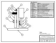
The following diagram shows the holes required to mount the mill and the clear<br />
area around the bolt pattern to allow use and maintenance of the mini mill.<br />
Mount the mill to the workbench with 3/8” or 10 mm bolts. The bolts should be<br />
about 1” (25 mm) longer than the thickness of the workbench. Use fender<br />
washers on the underside of wooden benches to prevent the nuts from pulling<br />
through.<br />
Operating Controls<br />
There are several controls used to operate the mill. Become familiar with them<br />
before you use the mill.<br />
8
Motor Controls<br />
1<br />
2<br />
1. Power switch<br />
2. Speed control<br />
The power switch latches in the off position when you press the big red button.<br />
To turn the switch on, slide the big red button in the direction of the arrow.<br />
The big red button will swing up to the on position.<br />
The power switch interrupts the input power to the speed control circuit<br />
board.<br />
You control the motor speed by adjusting a potentiometer that provides the<br />
speed setting value to the speed control circuit board. There is a safety switch<br />
on the speed control potentiometer that forces you to return the control to<br />
minimum speed when starting the mill.<br />
Always turn the speed control to the minimum speed position before starting<br />
the mill. Starting the mill with the speed control set to a higher speed can<br />
damage the speed control circuit board.<br />
To power up the mill:<br />
1. Turn the speed control to the minimum speed position.<br />
2. Turn on the power by sliding the red cover of the switch up to release the<br />
latch.<br />
Always turn the power off when you leave the mill. Leaving the power on can<br />
damage the speed control circuit board.<br />
To power down the mill:<br />
1. Turn the speed control to the minimum speed position.<br />
2. Turn off the power by latching the red cover of the switch.<br />
9
To start the mill:<br />
1. Ensure that the speed control is set to the minimum speed position.<br />
2. Advance the speed control to the desired speed.<br />
To stop the mill:<br />
• Turn the speed control to the minimum speed position.<br />
High/Low Speed Shifter<br />
The high/low speed shifter is on the left side of the spindle housing. It selects<br />
the spindle speed range.<br />
Low speed range<br />
0-1100 RPM<br />
High speed range 0-2500 RPM<br />
Never move this lever when the mill is turning. You might need to turn the<br />
spindle slightly by hand as you move the high/low speed shifter to engage the<br />
gears.<br />
X-Axis Hand Wheel<br />
The X-axis hand wheel moves the table to the left or right, depending on which<br />
way it is turned. Use this hand wheel to position the table.<br />
The dial on this handle indicates the relative position of the table. The<br />
graduated dial can be repositioned for convenience. Each division of the dial<br />
represents a movement of 0.001”.<br />
On some mini mills there are 62.5 divisions on the dial. On these mills, each<br />
full turn of the hand wheel moves the table 1/16” (0.0625”).<br />
Other mini mills have 50 graduations on the dial. On these mills, each full turn<br />
of the hand wheel moves the table 0.050”.<br />
10
X-Axis Lock Lever<br />
The X-axis lock lever is on the front of the saddle behind the Y-axis hand<br />
wheel. Use this lever to lock the X-axis so it does not move inadvertently.<br />
Pulling out on the lever and simultaneously turning it can change the locked<br />
position of this lever. Pulling out disengages the lever from the locking screw<br />
and allows it to move to a different position. You might need to adjust the<br />
screw in the base of the lever before you can disengage the lever.<br />
Y-Axis Hand Wheel<br />
The Y-axis hand wheel moves the table to the front or back, depending on<br />
which way it is turned. Use this hand wheel to position the table.<br />
The dial on this handle indicates the relative position of the table. The<br />
graduated dial can be repositioned for convenience. Each division of the dial<br />
represents a movement of 0.001”.<br />
On some mini mills there are 62.5 divisions on the dial. On these mills, each<br />
full turn of the hand wheel moves the table 1/16” (0.0625”).<br />
Other mini mills have 50 graduations on the dial. On these mills, each full turn<br />
of the hand wheel moves the table 0.050”.<br />
Y-Axis Lock Lever<br />
The Y-axis lock lever is on the right side of the saddle behind the X-axis hand<br />
wheel. Use this lever to lock the Y-axis so it does not move inadvertently.<br />
Pulling out on the lever and simultaneously turning it can change the locked<br />
position of this lever. Pulling out disengages the lever from the locking screw<br />
and allows it to move to a different position. You might need to adjust the<br />
screw in the base of the lever to make this adjustment.<br />
Z-Axis Coarse Feed Handles<br />
The Z-axis coarse feed handles are on the right side of the spindle housing. The<br />
three long handles allow you to quickly lower and raise the head. Use them to<br />
position the mill head, and also for drilling.<br />
Z-Axis Fine Feed Knob<br />
The Z-axis fine feed knob is located on the right front corner of the spindle<br />
housing. Use this knob to make find adjustments to the position of the head<br />
assembly.<br />
There are 60 divisions on the dial. Each full turn of the knob moves the head<br />
assembly 0.060”. Each division of the dial represents a movement of 0.001”.<br />
To engage the Z-axis fine feed:<br />
• Move the hub and coarse feed handles in to engage the dog clutch. You<br />
might need to turn the Z-axis fine feed knob to align the dogs.<br />
11
To disengage the Z-axis fine feed:<br />
• Move the hub and coarse feed handles out to disengage the dog clutch. You<br />
might need to turn the Z-axis fine feed knob to relieve pressure from the<br />
dogs.<br />
Fine feed disengaged<br />
Fine feed engaged<br />
Z-Axis Lock Lever<br />
The Z-axis lock lever is on the right side of the head assembly behind the Z-axis<br />
coarse feed hub. Use this lever to lock the Z-axis so it does not move<br />
inadvertently.<br />
Pulling out on the lever and simultaneously turning it can change the locked<br />
position of this lever. Pulling out disengages the lever from the locking screw<br />
and allows it to move to a different position. You might need to adjust the<br />
screw in the base of the lever to make this adjustment.<br />
Adjustments<br />
Keeping your mini mill in adjustment is an on-going process. You should check<br />
all the following adjustments when you set up your mill and then periodically<br />
as you use your mill.<br />
X-Axis Gib<br />
A gib is a strip of metal placed between the bearing surface of two machine<br />
parts to ensure a precision fit and provide adjustment for wear. The mini mill<br />
has gibs in several places, including between the saddle and the table.<br />
The X-axis gib provides adjustment for the mating dovetails on the saddle and<br />
the table that provide the X-axis (crosswise) motion.<br />
To adjust the X-axis gib:<br />
1. Loosen the four lock nuts on the front of the saddle.<br />
2. Slightly loosen all four setscrews on the front of the saddle.<br />
3. Snug each setscrew equally. This will lock the table in position.<br />
12
4. Loosen each setscrew 1/8 turn to allow the table to move.<br />
5. While holding the setscrews from turning, tighten the lock nuts.<br />
6. Test by turning the hand wheel. Loosen or tighten all the setscrews the<br />
same amount until the table moves <strong>free</strong>ly, but without play in the dovetail.<br />
X-axis gib adjusting screws<br />
Y-Axis Gib<br />
The Y-axis gib provides adjustment for the mating dovetails on the base and<br />
the saddle that provide the Y-axis (in and out) motion.<br />
To adjust the Y-axis gib:<br />
1. Loosen the two lock nuts on the right side of the saddle.<br />
2. Slightly loosen both setscrews on the right side of the saddle.<br />
3. Snug each setscrew equally. This will lock the saddle in position.<br />
4. Loosen each setscrew 1/8 turn to allow the saddle to move.<br />
5. While holding the setscrews from turning, tighten the lock nuts.<br />
6. Test by turning the hand wheel. Loosen or tighten both setscrews the same<br />
amount until the saddle moves <strong>free</strong>ly, but without play in the dovetail.<br />
Z-Axis Gib<br />
The Z-axis gib provides adjustment for the mating dovetails on the column and<br />
the head assembly that provide the Z-axis (vertical) motion.<br />
To adjust the Z-axis gib:<br />
1. Loosen the four lock nuts on the right side of the head assembly.<br />
2. Slightly loosen all four setscrews on the right side of the head assembly.<br />
3. Snug each setscrew equally. This will lock the head assembly in position.<br />
4. Loosen each setscrew 1/8 turn to allow the head assembly to move.<br />
5. While holding the setscrews from turning, tighten the lock nuts.<br />
6. Test by turning the Z-axis coarse feed handles. Loosen or tighten all the<br />
setscrews the same amount until the head assembly moves <strong>free</strong>ly, but<br />
without play in the dovetail.<br />
13
Tramming the <strong>Mill</strong><br />
Tramming is the process of squaring the spindle with the table on a mill. This is<br />
important on the mini mill because the angle of the head is adjustable from<br />
side to side. Because the column is held in position by a clamping mechanism,<br />
the angle of the spindle can change without you being aware.<br />
Tramming the mill requires the use of a dial indicator, or better, a dial test<br />
indicator. The indicator is mounted so that it rotates with the spindle and<br />
reads against the table at the farthest distance possible from the spindle.<br />
The indicator can be mounted with a test indicator holder, or with a simple<br />
shop-made holder.<br />
To tram the mill:<br />
1. While supporting the head and column, loosen the large nut at the back of<br />
the base of the column.<br />
2. Tighten the nut so that the column can just be moved.<br />
3. Mount the dial indicator or dial test indicator so that it will rest on the front<br />
left and front right corners of the table.<br />
14
4. Take readings on the left front and right front corners of the table.<br />
Calculate the difference to see how much and which way to move the top of<br />
the column.<br />
5. Move the column and take additional readings. Repeat until the readings are<br />
the same to within 0.001”.<br />
6. Tighten the large nut at the back of the base of the column.<br />
Motor to Intermediate Gear Adjustment<br />
A metal gear on the motor drives a plastic gear on the top of the intermediate<br />
shaft. If these gears are not meshed properly, they can make a lot of noise. It<br />
is easy to adjust the mesh to minimize the noise.<br />
To adjust the motor to intermediate gear mesh:<br />
1. Slightly loosen the four socket head cap screws that attach the motor<br />
mount.<br />
15
2. Shift the mill into high gear.<br />
3. Turn on the mill to approximately half speed.<br />
4. Move the motor until the gear noise is minimized.<br />
5. Tighten the four socket head cap screws that attach the motor mount.<br />
Lubrication<br />
We recommend the use of two lubricants on your mill. Where oil is required,<br />
we recommend Mobil 1 synthetic motor oil. Mobil 1 far exceeds the lubrication<br />
needs of the mini mill, and maintains a good surface film between applications.<br />
Any of the available viscosities work fine. Where grease is required, we<br />
recommend Lubriplate 630-AA lithium (white) grease. Lithium grease is a<br />
plastic-friendly grease that is widely available and easy to use.<br />
Before each use, lubricate the following points with Mobil 1 or other suitable<br />
oil.<br />
• Oil the column dovetail and rack.<br />
The following points on your mini mill require lubrication.<br />
Location Lubricant Frequency Notes<br />
Table and other<br />
machined<br />
surfaces<br />
Table dovetails<br />
Table feed screws<br />
and nuts<br />
X-axis thrust<br />
bearings<br />
Transmission<br />
gears<br />
Mobil 1<br />
motor oil<br />
Lithium<br />
grease<br />
Lithium<br />
grease<br />
Mobil 1<br />
motor oil<br />
Lithium<br />
grease<br />
Daily<br />
Yearly<br />
Yearly<br />
Yearly<br />
Yearly<br />
Oil lubricates and prevents<br />
corrosion<br />
See procedure below for<br />
lubricating the transmission gears<br />
without removing the spindle<br />
housing.<br />
The spindle and intermediate shaft bearings are deep groove ball bearings that<br />
are shielded and do not require additional lubrication.<br />
Lubricating the Transmission Gears<br />
You can lubricate the transmission gears without removing the spindle housing<br />
by using a spray can of lithium grease.<br />
To lubricate the transmission gears:<br />
1. Unplug the power cord.<br />
16
2. Remove the cap screw and plastic bushing that limits the upward travel of<br />
the Z-axis.<br />
3. Raise the head assembly up the column until the rack disengages from the<br />
gear.<br />
4. Manually raise the head assembly until the top of the head assembly is<br />
about 1.5" above the top of the column.<br />
5. Use the Z-axis locking lever to lock the head assembly in this position.<br />
6. Insert the lithium grease can’s spray tube into the opening that has been<br />
exposed in the back of the head assembly.<br />
7. Spray the grease while rotating the spindle by hand.<br />
8. Shift the high/low shifter to the opposite position.<br />
9. Spray the grease while rotating the spindle by hand.<br />
10. Release the Z-axis locking lever and lower the head assembly until it<br />
engages the rack.<br />
11. Continue to lower the head assembly using the Z-axis coarse feed handles.<br />
12. Replace the cap screw and plastic bushing that limits the upward travel of<br />
the Z-axis.<br />
Changing Spindle Tools<br />
The tools you work with are held in the mini lathe spindle by the taper. It is<br />
either an R8 taper or 3 Morse taper.<br />
Morse<br />
taper end<br />
mill holder<br />
R8 taper<br />
end mill<br />
holder<br />
The tools are held in the spindle by the drawbar. The drawbar is effectively a<br />
long bolt that goes down through the spindle and retains the tool.<br />
To remove a tool from the spindle:<br />
1. Remove the plastic cap from the top of the spindle.<br />
2. Insert the spindle lock pin the hole in the side of the motor mounting plate.<br />
Turn the spindle by hand until the lock pin engages the hole in the spindle.<br />
17
3. Use a wrench to loosen the drawbar about ½ turn.<br />
4. Tap the top of the drawbar with a soft-faced hammer to disengage the<br />
taper.<br />
5. Hold the tool with one hand to prevent it from dropping, and unscrew the<br />
drawbar. Remove the tool.<br />
To install a tool into the spindle:<br />
1. Put the drawbar down through the spindle from the top.<br />
2. Put the tool up into the spindle and thread the drawbar into it.<br />
3. If you have an R8 spindle, rotate the tool until the locking pin engages the<br />
slot in the side of the tool.<br />
4. Hold the tool with one hand, and tighten the drawbar with a wrench. Do not<br />
use the spindle lock pin to tighten the drawbar, as you will make it too<br />
tight.<br />
5. Replace the plastic cap on the top of the spindle.<br />
Squaring a Vise<br />
When you mount a vise on the mill table, it is important that it be mounted<br />
square to the table. If your vise is not square to the table, you will not be able<br />
to produce accurate work.<br />
The vise is usually mounted with the long axis of the vise perpendicular to the<br />
long axis of the table. Thus the jaws are parallel to the X-axis of the mill.<br />
To square a vise on the table:<br />
1. Mount the vise on the table and snug, but don’t tighten, the mounting bolts.<br />
2. Open the vise jaws at least 1”.<br />
3. Put the 3/8” diameter post on the top dovetail of a dial test indicator.<br />
4. Put the dial test indicator post in a drill chuck, end mill holder, or collet in<br />
the mill’s spindle with the dial facing front.<br />
5. Move the X-, Y-, and Z-axis controls so the point of the dial test indicator is<br />
between the vise jaws and about 1/8” below the top of the vise jaws.<br />
18
6. Move the X-axis so the dial test indicator’s point is about 1/16” inside of<br />
one end of the vise jaws.<br />
7. Move the Y-axis so that the dial test indicator’s point contacts the fixed jaw<br />
of the vise. Continue moving the Y-axis to zero the dial test indicator.<br />
8. Move the X-axis so that the dial test indicator’s point wipes across the width<br />
of the fixed jaw of the vise.<br />
9. Take a reading when the point of the dial test indicator reaches the far end<br />
of the vise jaw.<br />
10. Move the Z-axis to raise the dial test indicator so that the point is above the<br />
vise jaws.<br />
11. Tap the vise with a dead-blow hammer to rotate it in the appropriate<br />
direction to reduce the reading on the dial test indicator.<br />
12. Repeat steps 5 through 11 until the reading on the dial test indicator is<br />
acceptable to you. You should be able to reduce the reading to 0.001” or<br />
less.<br />
13. Tighten the vise mounting bolts.<br />
Using Parallels<br />
Precision parallels are used to raise the workpiece off the bed of the vise to a<br />
position where you can mill the top surface. Parallels come in sets of graduated<br />
heights. Choose a pair of parallels that position the top surface of the work<br />
above the top of the vise jaws, while keeping enough material between the<br />
jaws of the vise for effective clamping.<br />
19
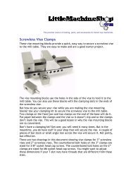
Clamping with a Clamping Kit<br />
The clamping kit is the “Erector set” of the milling machine. Use it to clamp<br />
large workpieces, fixtures, and even vises to the mill table.<br />
Use 1-2-3 blocks as part of your “Erector set”. They can be used to hold<br />
workpieces up off the table so you won’t drill into the table. They can be used<br />
to mount workpieces, and they can be used to set work up perpendicular to the<br />
mill table.<br />
When clamping with step blocks and clamp bars, the end of the clamp bar on<br />
the step block should be just a little higher than the end on the workpiece.<br />
This ensures that the end of the clamp bar makes contact with the workpiece.<br />
The stud should be located as close to the workpiece as possible so that the<br />
majority of the clamping force is exerted on the workpiece and not the step<br />
block.<br />
Finding the Edge of a Workpiece<br />
Once your work is secured on the table, the next step is to locate the edge of<br />
the work so you can zero the X- and Y-axis dials.<br />
20
Most engineering drawings show dimensions from two perpendicular edges of<br />
the workpiece. These are the two edges that you should “find,” or locate, as<br />
you zero the X- and Y-axis dials.<br />
The goal is to set the X- and Y-axis dials to zero with the centerline of the<br />
spindle directly over the respective edge of the workpiece. Then all<br />
movements of the workpiece relative to the spindle are referenced to these<br />
two edges.<br />
To find the left edge of a workpiece:<br />
1. Put the solid body of the edge finder in a collet or drill chuck in the mill’s<br />
spindle.<br />
2. Offset the movable end of the edge finder so that it is not concentric with<br />
the body.<br />
3. Move the edge finder so that it is clear of the workpiece beyond the left<br />
edge.<br />
4. Lower the mill’s head so that the smaller diameter section of the movable<br />
end of the edge finder is next to the workpiece.<br />
5. Turn the mill on and adjust the speed control to about half of full speed in<br />
the low speed range or about one third of full speed in the high speed<br />
range.<br />
With the edge finder spinning, it is obvious that the movable end of the<br />
edge finder is not concentric with the body.<br />
21
6. Slowly turn the X-axis hand wheel clockwise to move the table to the left.<br />
As the workpiece approaches the edge finder it first forces the movable end<br />
to become more concentric with the body.<br />
7. When the movable end of the edge finder is almost perfectly concentric<br />
with the body it will all of a sudden jump to one side and stay there.<br />
The point at which the movable end of the edge finder jumps to one side is<br />
the point you are looking for. Stop turning the X-axis hand wheel at this<br />
point.<br />
8. Turn the motor off.<br />
9. Raise the mill’s head so that the edge finder is completely above the<br />
workpiece.<br />
10. Set the X-axis dial to zero.<br />
11. Turn the X-axis hand wheel clockwise 0.100”. If your dials have 62.5<br />
divisions, you turn one full turn plus 37 and one half divisions. If your dials<br />
have 50 divisions, you turn two full turns.<br />
The movable end of the edge finder is 0.200” in diameter, so you are<br />
moving the distance from the center of the edge finder to the edge of the<br />
workpiece.<br />
12. Zero the X-axis dial.<br />
13. Note the location of the pointer relative to the X-axis scale across the front<br />
of the table. You may want to rotate the pointer so that it aligns with one<br />
of the tic marks on the scale.<br />
This is the zero point for your X-axis movements.<br />
Drilling<br />
There are several ways to locate the position at which you want to drill a hole.<br />
You can use your layout tools to scribe crossed lines at the hole location, and<br />
then use a wiggler to align the mill’s spindle over the intersection of the<br />
scribed lines.<br />
You can use an edge finder to locate two edges of the workpiece, and then use<br />
the X- and Y-axis hand wheels and dials to locate the correct location.<br />
Once you find the location, start the hole with a center drill or spotting drill.<br />
These specialized drills have relatively large diameter shanks to prevent<br />
bending or wobble as you start the hole. This ensures that the hole is located<br />
directly below the center of the spindle.<br />
Next, drill a pilot hole about 1/8” in diameter (but not larger than the final<br />
size you need).<br />
Finally, drill to the final drill size you need. You can drill the final hole size as<br />
long as two conditions are met. First, the web of the drill bit (the short straight<br />
section at the very tip of the drill) must fit into the pilot hole. Second, the drill<br />
must not be too large for the mini mill to drive. If power is an issue, use<br />
smaller drills to reach the final diameter in steps.<br />
22
<strong>Mill</strong>ing<br />
You can use collets or end mill holders to hold end mills. The world is split<br />
about 50/50 on which is better. We will give you the arguments for both sides<br />
and let you decide.<br />
Collets<br />
Collets are shorter than end mill<br />
holders and so give you more vertical<br />
work area.<br />
Collets grip the end mill all the way<br />
around and so provide a better grip.<br />
Collets are more concentric than end<br />
mill holders because they grip all the<br />
way around the end mill's shank.<br />
Collets are less expensive than end<br />
mill holders and so can be replaced<br />
when they wear out.<br />
It's fun juggling an end mill, a collet,<br />
and a drawbar all at the same time<br />
End <strong>Mill</strong> Holders<br />
End mill holders are longer than<br />
collets and so let you reach nearer the<br />
mini mill's table.<br />
End mill holders have a setscrew that<br />
bears on the flat on the shank of the<br />
end mill and so ensure that the end<br />
mill cannot slip.<br />
Because they fit the end mill closely<br />
end mill holders ensure concentricity.<br />
End mill holders are more robust than<br />
collets and are less prone to wear out.<br />
It is easier to replace an end mill in an<br />
end mill holder because the end mill<br />
holder can remain in the spindle.<br />
Whether you choose end mill holders or collets, they are used to hold an end<br />
mill in the spindle of the mini mill.<br />
End mills are called that because they cut on the end, as well as on the<br />
periphery. Earlier milling cutters used in horizontal milling machines only cut<br />
on the periphery. This makes end mills versatile. You can mill the sides of a<br />
workpiece, the top surface of a workpiece, and even cut slots and holes in a<br />
workpiece.<br />
23
Conventional <strong>Mill</strong>ing Versus Climb <strong>Mill</strong>ing<br />
Climb <strong>Mill</strong>ing<br />
Conventional <strong>Mill</strong>ing<br />
Depending on the direction in which you move the workpiece against the end<br />
mill you are either climb milling or conventional milling. As shown in the<br />
illustration above, you are climb milling when the end mill turns as to climb the<br />
slope made by cutting.<br />
Climb milling has several advantages, and is often recommended for modern<br />
milling machines. The flutes dig in to material with a climbing action, and the<br />
workpiece and rotation of the cutter are going in the same direction. With this<br />
forward stroke the tooth starts with a full chip and pushes the workpiece down<br />
against the table or holding device. This requires less machine power, the<br />
cutter does not dull as soon, and a better surface finish is produced.<br />
However, climb milling requires a very rigid milling machine with virtually no<br />
backlash. Because the workpiece and the milling cutter are moving in the same<br />
direction, the milling cutter tends to pull the workpiece away from the driving<br />
device if there is any backlash. This can overload the cutter and stall the<br />
machine. Or it can simply leave a poor surface finish.<br />
On light mills like the mini mill, use conventional milling for all but the lightest<br />
cuts. Then, take your final cut of one or two thousandths of an inch using climb<br />
milling for the best surface finish.<br />
Plunge <strong>Mill</strong>ing<br />
Plunge milling is the same action as drilling, but using a center cutting end mill<br />
instead of a drill bit. This is how you start a slot that does not extend to the<br />
edge of the workpiece.<br />
Some end mills are center cutting. This means that one of the cutting edges on<br />
the end of the end mill extends across the center of the end mill so that there<br />
is a cutting edge for the full diameter of the end of the end mill.<br />
Non–center cutting end mills have cutting edges on the end, but they do not<br />
extend to the center. These end mills will cut on the end and can be used for<br />
slotting and surfacing, but you cannot plunge a non–center cutting end mill<br />
straight down into the workpiece.<br />
24
<strong>Mill</strong>ing Slots<br />
<strong>Mill</strong>ing slots is the signature operation for a vertical milling machine. For<br />
example, to make a belt-adjustment slot, you plunge mill through the<br />
workpiece at one end of the slot, mill the length of the slot and raise the end<br />
mill at the other end.<br />
But of course, life is not as simple as this. You may or may not be able to<br />
remove all the material in one pass. If the workpiece is thick you might need to<br />
make multiple passes along the length of the slot, lowering the end mill<br />
between passes.<br />
And, if you use an end mill where the diameter of the end mill is the same as<br />
the width of the slot, you are conventional milling on one side of the slot, and<br />
climb milling on the other. You will see markedly different surface finishes on<br />
the two sides of the slot. But since slots usually need to provide some<br />
clearance for the bolt that will go through them, the solution is easy. Use an<br />
end mill the same size as the bolt, then take a few cleanup passes to widen the<br />
slot slightly wider than the end mill diameter. Your final passes should be<br />
climb-milling passes on each side of the slot.<br />
Surfacing<br />
Surfacing is used to square a workpiece and to provide a good-looking surface<br />
as well as to change the size of a workpiece.<br />
If you are trying to make a good-looking surface, use as large a diameter cutter<br />
as is practical. While a fly cutter can surface a large area in one pass, we do<br />
not recommend their use on the mini mill. If the single point tool in the fly<br />
cutter catches on the work, it almost guarantees that the mini mill will break a<br />
gear. It is prudent to use a smaller diameter cutter, such as an indexable end<br />
mill for surfacing.<br />
Common Accessories<br />
You will soon find that the purchase of a mill is just an initial step. There are<br />
many tools and accessories that you will need to get full use from your mill.<br />
Following are some common accessories used with the mini mill.<br />
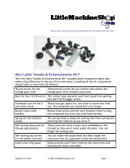
End <strong>Mill</strong>s<br />
Conventional wisdom is that 2-flute end mills are used on aluminum, while 4-<br />
flute end mills are used on steel and brass. Take a look at why before you make<br />
a choice.<br />
25
Two flute end mills<br />
Four flute end mills<br />
Two-flute end mills are used on aluminum because aluminum is easy to<br />
machine and you can take big cuts. Two-flute end mills provide a lot of room<br />
between the flutes for the big chips produced when making heavy cuts. But on<br />
a mini mill, you are probably not as concerned about maximizing production,<br />
and thus you are not taking the same big cuts that a production shop might.<br />
Four-flute end mills can produce a slightly better finish at the same cutting<br />
speeds because there are twice as many cutting edges, each taking off half as<br />
much material. But again, if you are not trying to maximize production, you<br />
can simply slow the feed rate with a 2-flute end mill for the same effect.<br />
End mills are also classed as "center cutting" or "non–center cutting." With a<br />
center cutting end mill, you can plunge the end mill into the work as you would<br />
a drill. This is important if you are cutting a slot that does not extend to the<br />
edge of the part. Center cutting end mills are easy to identify. If the flutes<br />
meet in the middle of the end of the end mill, it is a center cutting end mill. In<br />
some cases, one of the flutes will be longer, reaching right to the center. If the<br />
flutes stop short of the center, leaving a space with no flutes in the center, it<br />
is a non–center cutting end mill. Virtually all 2-flute end mills are center<br />
cutting end mills. Currently, most 4-flute end mills are center cutting. All the<br />
end mills that <strong>Little</strong><strong>Machine</strong><strong>Shop</strong>.com sells are center cutting end mills.<br />
The 6-piece end mill sets we sell are economical starter sets. Because all the<br />
end mills in the set have 3/8" shanks, you only need one end mill holder or<br />
collet to use the entire set.<br />
Work Holding<br />
There are two main ways to hold work on a mill's table: with a vise or by<br />
clamping the workpiece to the table. In our experience, most work can be held<br />
in a vise. But from time to time there is a large or odd-shaped workpiece that<br />
must be clamped to the table.<br />
Vises<br />
There is a range of different types of vises that you can use on a mini mill.<br />
26
Choose a vise that will handle the work you do. You don't need a 3" vise if the<br />
parts you make are a half inch long. While you can usually put small parts in a<br />
large vise, it is more convenient to use an appropriate-size vise.<br />
Vise jaws are often too deep for the work. In general, you want the top of the<br />
workpiece to extend above the top of the vise jaws. To fill the gap from the<br />
bottom of the workpiece to the "ways" of the vise, you use parallels. Parallels<br />
are strips of metal that have been carefully ground so that the top and bottom<br />
edges are parallel with very tight tolerances. They usually come in matched<br />
pairs. Place one parallel adjacent to each jaw in the vise and place the<br />
workpiece so it rests on the parallels.<br />
Clamping Kits and Accessories<br />
Clamping kits and their accessories, including 1-2-3 blocks, are the "Erector<br />
Sets" of work holding. Use the various pieces of the clamping kit as you see fit<br />
to hold workpieces to the mini mill's table.<br />
In many cases, you need to lift the workpiece off the table, either because the<br />
mill spindle won't reach it or because of a projection on the bottom of the<br />
workpiece. 1-2-3 blocks are precision ground to be flat and parallel. Use them<br />
as spacers to lift the workpiece. You can also use them as an angle plate by<br />
bolting a workpiece to the side of the 1-2-3 block and then clamping the 1-2-3<br />
block to the mill table.<br />
27
Setup Tools<br />
Once you have your workpiece mounted on the mini mill, you are ready to start<br />
cutting metal. Except for one thing: You don't know where the cutting tool is in<br />
relation to the workpiece. Edge finders and center finders help you determine<br />
the relationship between the cutting tool and the workpiece.<br />
Edge finders locate the edge of the workpiece. Center finders locate the center<br />
of existing holes. Wigglers locate the intersection of scribed lines on the<br />
workpiece.<br />
Maintenance<br />
Maintenance of the mini mill is simple, but important. Regular maintenance<br />
will keep your mini mill working like new for many years.<br />
Cleaning<br />
The maintenance you perform most often is cleaning. Keeping swarf off of<br />
wearing surfaces is the most important thing you can do to prolong the life of<br />
your mini lathe.<br />
• Use a 1” paintbrush to remove swarf from the machine as you work.<br />
• Clean swarf from the mill, from top down after each use.<br />
Motor Brushes<br />
The motor brushes can be replaced without removing the motor. Follow these<br />
steps.<br />
1. Unplug the power cord.<br />
2. Unscrew the motor brush retainers from the sides of the motor.<br />
3. Replace the motor brushes.<br />
4. Replace the motor brush retainers.<br />
28