Seat Ibiza (SE 250) Seat Ibiza ST (SE 253)
Seat Ibiza (SE 250) Seat Ibiza ST (SE 253)
Seat Ibiza (SE 250) Seat Ibiza ST (SE 253)

You also want an ePaper? Increase the reach of your titles
YUMPU automatically turns print PDFs into web optimized ePapers that Google loves.
<strong>Seat</strong> <strong>Ibiza</strong> (<strong>SE</strong> <strong>250</strong>)<br />
(2008→)<br />
<strong>Seat</strong> <strong>Ibiza</strong> <strong>ST</strong> (<strong>SE</strong> <strong>253</strong>)<br />
(2010→)<br />
Návod k obsluze a montáži<br />
Betriebs und Montageanleitung<br />
Owner’s and fitting Manual<br />
TMB PS 056<br />
SPOJOVACÍ - TAŽNÉ ZAŘÍZENÍ<br />
VERBINDUNGS – ANHÄNGERKUPPLUNG<br />
TRAILER COUPLING DEVICE<br />
pro automobily<br />
Für Personenkraftwagen<br />
for passenger cars<br />
<strong>Seat</strong> <strong>Ibiza</strong> (<strong>SE</strong> <strong>250</strong>, <strong>SE</strong> <strong>253</strong>)<br />
s odnímatelným tažným ramenem<br />
mit demontierbarem Zugarm<br />
with removable towbar<br />
e8 * 94/20 * 0095<br />
© 17.6.2010
- 2 -
- 3 -
- 4 -
- 5 -
- 6 -<br />
CZ<br />
TAŽNÉ ZAŘÍZENÍ<br />
Upozornění<br />
Díl „Tažné zařízení“, TMB PS 056 je určen pro vozy <strong>Seat</strong> <strong>Ibiza</strong>. Montáž vyžaduje použití speciálního<br />
nářadí a dílenských příruček.<br />
Tažné zařízení je vyrobeno podle schválené dokumentace a odpovídá homologaci e8*<br />
94/20* 0095.<br />
Všeobecné údaje<br />
Konstrukce tažného zařízení odpovídá všem českým i mezinárodním předpisům. Zařízení prošlo<br />
pevnostními zkouškami dle evropské směrnice ES 94/20. Konstrukce upínacího mechanizmu tažného<br />
ramena je chráněna osvědčením o zápise užitného vzoru č. 15848. Tažné rameno je opatřeno kulovým<br />
čepem o průměru 50 mm dle ISO 3853.<br />
Technické parametry<br />
Tažné zařízení je konstruováno pro připojení:<br />
brzděného přívěsu do maximální hmotnosti<br />
(platí údaj v technickém průkazu vozu)<br />
nebrzděného přívěsu do max. hmotnosti<br />
(platí údaj v technickém průkazu vozu)<br />
Průměr kulového čepu<br />
Max. svislé statické zatížení na kulový čep<br />
Dc - Wert (vztažná síla)<br />
1400 kg<br />
630 kg<br />
50 mm<br />
75 kg<br />
7,73 kN<br />
g - tíhové zrychlení (g = 9,81 ms -2 )<br />
T - max. hmotnost tažného vozidla [t]<br />
C - max. hmotnost přívěsu [t]<br />
Celková hmotnost tažného zařízení<br />
Rozměry<br />
17,8 kg<br />
1013 x 662 x 234 mm<br />
Upozornění<br />
K montáži tažného zařízení TMB PS 056 je nutné navíc objednat tyto díly:<br />
krytka otvoru zadního nárazníku<br />
sada elektrické instalace pro tažné zařízení<br />
V případě potřeby:<br />
adaptér (z 13ti-pólové zásuvky na 7-pólovou zásuvku)
Náhradní díly k sadě<br />
náhradní tažné rameno<br />
náhradní zámek ovladací páčky tažného ramena<br />
krytka otvoru zadního nárazníku<br />
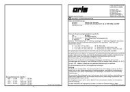
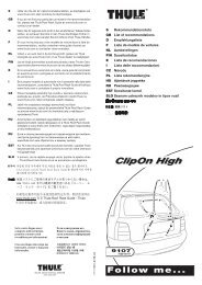
Sada tažného zařízení TMB PS 056 obsahuje (obr. 1)<br />
Název dílu Kusů Pozice<br />
Nosník úplný s držákem zásuvky 1 A<br />
Šroub M10 x 35 4 B<br />
Tažné rameno 1 C<br />
Krytka kulového čepu tažného ramena 1 D<br />
Klíč k zámku ovladací páčky 2 E<br />
Krytka upínacího pouzdra 1 F<br />
Samolepicí štítek “75 kg” 1 G<br />
Montážní návod + šablona<br />
Návod k obsluze<br />
K montáži tažného zařízení je nutné objednat díl „krytka otvoru zadního nárazníku“ 5P0 803 595<br />
Seznam speciálního nářadí<br />
Univerzální čistič<br />
Momentový klíč<br />
Nástroj pro vyříznutí otvoru do nárazníku<br />
- 7 -<br />
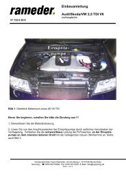
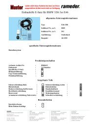
Postup montáže<br />
- Ustavte vozidlo na ramena dílenského zvedáku.<br />
- Demontujte zadní nárazník (lapače nečistot jsou-li na vozidle) a nosník zadního nárazníku.<br />
- Uvolněte vložky zadních blatníků.<br />
Vystřižení otvoru do zadního nárazníku<br />
- 2 -<br />
- Demontovaný zadní nárazník položte na měkkou plstěnou podložku vnější stranou směrem nahoru.<br />
- Vhodným nástrojem vyřízněte potřebný otvor v nárazníku dle šablony. Vyříznutý otvor začistěte po<br />
celém jeho obvodu.<br />
Montáž tažného zařízení na vozidlo<br />
- 3 -<br />
- Strhněte záslepky otvorů pro uchycení tažného zařízení na zadních podélnících (obě strany vozu) -šipky-<br />
. V případě potřeby odstraňte části plastizolu uvnitř podélníků.<br />
- 4 -<br />
- Tažné zařízení (A) nasuňte podélnými nosníky do otvorů na zadním čele vozu a ustavte jej do správné<br />
polohy.<br />
- Nosníky přišroubujte pomocí čtyř šroubů M10 x 35 (B) k podvozku vozu.<br />
- Tažné zařízení zatáhněte směrem dozadu od vozu a šrouby (střídavě) na obou stranách dotáhněte<br />
utahovacím momentem 70 Nm.<br />
- 5,6 -<br />
- Vyzkoušejte nasazení tažného ramena (C) do upínacího pouzdra nosníku tažného zařízení (viz. návod k<br />
obsluze tažného zařízení) a uložte ho do zavazadlového prostoru.
- 8 -<br />
- Do upínacího pouzdra nosníku tažného zařízení nasaďte krytku (F).<br />
Pokračujte montáží elektrické instalace tažného zařízení na vozidlo (viz. návod k montáži elektrické<br />
instalace) .<br />
Po skončení montáže elektrické instalace namontujte zpět všechny demontované díly a příslušné spoje<br />
utáhněte předepsanými utahovacími momenty.<br />
- 7 -<br />
- Samolepicí štítek 75 kg (G) nalepte po skončení montáže nad výřez v zadním nárazníku (místo před<br />
nalepením očistěte a odmastěte čističem).<br />
- 8 -<br />
- Nacvakněte krytku do otvoru zadního nárazníku.
- 9 -<br />
D<br />
ANHÄNGERKUPPLUNG<br />
Hinweis<br />
Bauteil „Anhängerkupplung“, TMB PS 056 ist für Fahrzeuge <strong>Seat</strong> <strong>Ibiza</strong> bestimmt. Der Einbau verlangt<br />
Sonderwerkzeuge und Reparaturleitfäden.<br />
Die Anhängerkupplung wurde gemäβ Zulassungsdokumentation hergestellt und entspricht der<br />
Homologation e8* 94/20* 0095.<br />
Allgemeine Daten<br />
Die Konstruktion der Anhängerkupplung entspricht allen tschechischen sowie internationalen<br />
Vorschriften. Die Anhängerkupplung hat die Festigkeitsprüfungen laut europäischer Richtlinie EG<br />
94/20 bestanden. Die Konstruktion der Klemmeinrichtung vom Schlepparm ist durch die<br />
Beschenigung über Eintragung des Gebrauchsmusters Nr. 15848 geschützt. Der Schlepparm ist mit einem<br />
Kugelzapfen von einem Durchmesser 50 mm gemäβ ISO 3853 versehen.<br />
Technische Angaben<br />
Die Anhängerkupplung ist konstruiert zum Anschluss:<br />
des gebremsten Anhängers zum Höchstgewicht<br />
(es gilt die Angabe im Fahrzeugbrief)<br />
des nicht gebremsten Anhängers zum Höchstgewicht<br />
(es gilt die Angabe im Fahrzeugbrief)<br />
Kugelbolzen-Durchmesser<br />
Maximale vertikale statische Last auf den Kugelbolzen<br />
Dc - Wert (Bezugskraft)<br />
1400 kg<br />
630 kg<br />
50 mm<br />
75 kg<br />
7,73 kN<br />
g - Fallbeschleunigung (g = 9,81 ms-2)<br />
T – Höchstgewicht des Schleppfahrzeuges [t]<br />
C - Höchstgewicht des Anhängers [t]<br />
Gesamtgewicht der Anhängerkupplung<br />
Maβe<br />
17,8 kg<br />
1013 x 662 x 234 mm<br />
Hinweis<br />
Zum Einbau der Ahängerkupplung TMB PS 056 müssen noch zusätzlich folgende Bauteile bestellt<br />
werden:<br />
Abdeckung für die Öffnung des Stoßfängers hinten<br />
Elekroinstallation-Satz für Ahängerkupplung<br />
Bei Bedarf:<br />
Adapter (aus der 13-poligen Steckdose auf die 7-polige Steckdose)
- 10 -<br />
Ersatzteile zum Satz<br />
Ersatzschlepparm<br />
Ersatzschloss zum Betätigungshebel des Schlepparmes<br />
Abdeckung für die Öffnung des Stoßfängers hinten<br />
Anhängerkupplung-Satz TMB PS 056 beinhaltet (Abb. 1)<br />
Teilebezeichnung Stück Position<br />
Träger komplett mit Steckdosenhalter 1 A<br />
Schraube M10 x 35 4 B<br />
Schlepparm 1 C<br />
Abdeckung für Kugelzapfen des Schlepparmes 1 D<br />
Schlüssel zum Klemmhebelschloss 2 E<br />
Abdeckung für Spannhülse 1 F<br />
Selbstklebeschild „75 kg“ 1 G<br />
Montageanleitung + Schablone<br />
Betriebsanleitung<br />
Zum Einbau der Anhängerkupplung müssen noch Bauteil „Abdeckung für die Öffnung des<br />
Stoßfängers hinten“ 5P0 803 595 bestellt werden<br />
Verzeichnis der Sonderwerkzeuge<br />
Universalreiniger HHA 381 011<br />
Drehmomentschlüssel<br />
Werkzeug zum Schneiden der Öffnung in den Stoßfänger<br />
Montagereihenfolge<br />
- Stellen Sie das Fahrzeug auf die Werkstattheberarme.<br />
- Bauen Sie den Stoβfänger hinten (Schmutzfänger, wenn am Fahrzeug vorhanden) und<br />
Stoβfängerträger hinten aus.<br />
- Lösen Sie die Radhausschalen hinten.<br />
Öffnung im Stoβfänger hinten ausschneiden<br />
- 2 -<br />
- Legen Sie den ausgebauten Stoβfänger hinten auf eine Filzunterlage mit der Auβenseite nach oben.<br />
- Die erforderliche Bohrung im Stoßfänger mit einem geeigneten Werkzeug je nach herausschneiden.<br />
Anhängerkupplung an das Fahrzeug montieren<br />
- 3 -<br />
- Reiβen Sie die Blindverschlüsse der Öffnungen zur Befestigung der Anhängerkupplung an den<br />
Längsträgern hinten (beide Fahrzeugseiten) -Pfeile- ab. Entfernen Sie bei Bedarf die Plastisolteile in den<br />
Längsträgern innen.<br />
- 4 -<br />
- Setzen Sie die Anhängerkupplung (A) durch die Längsträger in die Öffnungen am hinteren<br />
Fahrzeugstirn ein und richten Sie sie in die richtige Lage ein.<br />
- Schrauben Sie die Träger mit vier Schrauben M10 x 35 (B) an das Fahrwerk des Fahrzeugs an.<br />
- Ziehen Sie die Anhängerkupplung nach hinten vom Fahrzeug und schrauben Sie die Schrauben<br />
(abwechselnd) auf beiden Seiten mit Anzugsdrehmoment 70 Nm.
- 11 -<br />
- 5, 6 -<br />
- Prüfen Sie das Einsetzen des Schlepparmes (C) in der Spannhülse des Trägers für Anhängerkupplung<br />
(siehe Betriebsanleitung der Anhängerkupplung) und verstauen Sie den Arm im Kofferraum.<br />
- Setzen Sie die Abdeckung (F) in die Spannhülse des Trägers für Anhängerkupplung ein.<br />
Weiter die Elektroinstallation der Anhängerkupplung ausführen (siehe Montageanleitung der<br />
Elektroinstallation).<br />
Nach Beendigung der Montage der Elektroinstallation bauen Sie wieder alle ausgebauten Teile ein und<br />
ziehen Sie die entsprechenden Anschlüsse mit vorgeschriebenen Anzugsdrehmomenten an.<br />
- 7 -<br />
- Kleben Sie das Selbstklebeschild 75 kg (G) nach Beendigung der Montage über dem Ausschnitt im<br />
Stoβfänger hinten an (reinigen und entfetten Sie vor dem Ankleben die Stelle mit Reiniger).<br />
- 8 -<br />
- Rasten Sie die Abdeckung in die Öffnung des Stoβfängers hinten ein.
- 12 -<br />
GB<br />
TOWING COUPLING<br />
Advice<br />
The part „Towing coupling“, TMB PS 056, is intended for vehicles <strong>Seat</strong> <strong>Ibiza</strong>. The fitting requires the use<br />
of special tooling and Workshop Manuals.<br />
The towing coupling is manufactured according to the approved documentation, and it complies<br />
with the homologation e8* 94/20* 0095.<br />
General data<br />
The design of the towing coupling meets all Czech and international regulations. The coupling has passed<br />
the strength tests in compliance with the European Directive EC 94/20; the design is protected with the<br />
certificate of the registration of the Utility Design No. 15848. The swing arm is fitted with a ball journal<br />
with a 50 mm diameter, in compliance with ISO 3853.<br />
Technical parameters<br />
The towing coupling has been designed for linking with:<br />
A trailer with brakes, up to maximum weight<br />
(consult the Technical Certificate of the car)<br />
A trailer without brakes, up to maximum weight<br />
(consult the Technical Certificate of the car)<br />
Diameter of the ball journal<br />
Max. vertical static load upon the ball journal<br />
Dc - Wert (relative strength)<br />
1400 kg<br />
630 kg<br />
50 mm<br />
75 kg<br />
7,73 kN<br />
g – gravity acceleration (g = 9,81 ms -2 )<br />
T – max. weight of the trailing vehicle [t]<br />
C – max. weight of the trailer [t]<br />
The total weight of the towing coupling<br />
Dimensions<br />
17,8 kg<br />
1013 x 662 x 234 mm<br />
Advice<br />
For the fitting of the towing coupling TMB PS 056 it is necessary to order additional parts as follows:<br />
cover of the hole of the rear bumper<br />
set of electric installation for the towing coupling<br />
In case of need:<br />
adapter (from the 13-pole socket to a 7-pole one)<br />
Spare parts for the set<br />
spare towing arm<br />
spare lock of the control lever of the towing arm<br />
cover of the hole of the rear bumper
- 13 -<br />
Set of the towing coupling TMB PS 056 includes (fig. 1)<br />
Name of part Pieces Position<br />
Complete beam with socket holder 1 A<br />
Screw M10 x 35 4 B<br />
Towing arm 1 C<br />
Cover of the ball journal of the towing arm 1 D<br />
Key to the lock of control lever 2 E<br />
Cover of the clamping bush 1 F<br />
Self-adhesive label “75 kg” 1 G<br />
Fitting instructions + template<br />
Operating instructions<br />
For the fitting of the towing coupling it is necessary to order part „Cover of hole of rear<br />
bumper“ 5P0 803 595<br />
List of special tools<br />
Universal de-greaser<br />
Torque wrench<br />
Tool for cutting a hole in the bumper<br />
Fitting procedure<br />
- Fix the vehicle upon the arms of a workshop jack.<br />
- Remove the rear bumper (including dirt strainers if the vehicle is provided with them) and the<br />
beam of the rear bumper.<br />
- Loosen the lining of the rear mud-guards.<br />
Cutting out a hole in the rear bumper<br />
- 2 -<br />
- Put the removed rear bumper upon a soft felt surface by its outer side upwards.<br />
- With a suitable tool cut out the necessary hole in the bumper depending the template. Clean the cut-out<br />
hole in its whole circumference.<br />
Fitting of the towing coupling in the vehicle<br />
- 3 -<br />
- Remove the cappings from the holes for clamping the towing coupling on the rear longitudinal girders<br />
(both sides of the vehicle) -arrows-. If necessary, remove parts of the plastic inside the longitudinal<br />
girders.<br />
- 4 -<br />
- Fit the towing coupling (A) by its longitudinal beams into the holes at the rear nose of the car and set it<br />
to the correct position.<br />
- By means of four screws M10 x 35 (B) fasten the beams to the chassis of the vehicle.<br />
- Pull the towing coupling backwards from the vehicle and tighten the screws (alternately) on both<br />
sides with the tightening torque of 70 Nm.<br />
- 5, 6 -<br />
- Check the fitting of the towing arm (C) in the clamping bush of the beam of the swing coupling (see the<br />
Operation Manual of the towing coupling) and deposit it into the luggage compartment.<br />
- Fit the cover (F) into the clamping bush of the beam of towing coupling.<br />
Next, proceed to the fitting of the electric installation of the towing coupling upon the vehicle (see<br />
the instructions for fitting the electric installation).<br />
Having finished the fitting of the electric installation, fit all the removed parts back to their places and<br />
tighten the respective connections at the prescribed torque moments.
- 14 -<br />
- 7 -<br />
- After the fitting has been finished, affix the self-adhesive label 75 kg (G) above the cutting in the rear<br />
bumper (before affixing it, clean and degrease the place with the de-greaser).<br />
- 8 -<br />
- Clamp the cover into the hole of the rear buffer.
- 15 -<br />
Montáž a demontáž tažného ramena<br />
Schlepparm einbauen und ausbauen<br />
Fitting and removing of the towing arm
- 16 -
- 17 -
- 18 -<br />
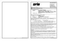
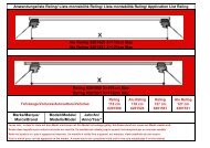
Montáž tažného ramena<br />
Tažné rameno vyjměte z boxu na nářadí v zavazadlovém prostoru.<br />
- 1 -<br />
- Vyjměte krytku otvoru zadního nárazníku (H) -šipka-<br />
- Krytku uložte na vhodné místo do zavazadlového prostoru vozu (s ohledem na možné poškození<br />
zácvaků).<br />
- 2 -<br />
- Vyjměte krytku (F) z otvoru upínacího pouzdra na nosníku tažného zařízení zatažením směrem dolů -<br />
šipka- a uložte ji na vhodné místo.<br />
- 3 -<br />
- Zkontrolujte, je-li tažné rameno v pohotovostní poloze.<br />
- Tzn. zajišťovací kolík ovladací páčky je zasunutý (je viditelná pouze jeho vrchní červená část) a klíček je<br />
v odemknuté poloze (je viditelná jeho červená značka) -detail šipky-.<br />
- 4 -<br />
Není-li tažné rameno z nějakého důvodu v pohotovostní poloze postupujte následujícím způsobem:<br />
- Odemkněte zámek ovladací páčky (otočením klíčku o 180° doleva).<br />
- Levou rukou uchopte tažné rameno pod kulovým čepem dle obrázku. Prsty pravé ruky zamáčkněte<br />
zajišťovací kolík až na doraz a zároveň pravou rukou stlačte dolů na doraz ovladací páčku. Ovladací<br />
páčka zůstane v této poloze zaaretována a tažné rameno je připraveno k použití.<br />
- 5 -<br />
- Nasuňte tažné rameno (C) do upínacího pouzdra nosníku tažného zařízení až do horní polohy upnutí.<br />
- Toto upnutí je provázeno zvukem (zaskočením upínacích kuliček do pouzdra), otočením ovladací páčky<br />
nahoru a vysunutím zajišťovacího kolíku (je viditelná jeho zelená část) -detail šipka-.<br />
- Sejměte krytku (D) z kulového čepu -šipka-.<br />
- 6 -<br />
- Otočením klíčku (E) o 180° vpravo uzamkněte zámek ovladací páčky (je viditelná jeho zelená značka)<br />
a klíček vyjměte.<br />
Zkontrolujte, je-li tažné rameno správně namontováno. Rukou (silným zacloumáním) vyzkoušejte<br />
jeho upevnění.<br />
- 7 -<br />
- Na zámek tažného ramena nasaďte krytku. Ujistěte se, že je krytka dobře nasazena.<br />
Upozornění<br />
- Pokud není tažné rameno v pohotovostní poloze, nelze jej upnout do upínacího pouzdra nosníku<br />
tažného zařízení.<br />
- Při upínání tažného ramena mějte ruce mimo dráhu upínací páčky. Při zpětném pohybu páčky do<br />
upínací polohy může dojít ke zranění prstů!<br />
- V případě, že není tažné rameno správně upnuté v upínacím pouzdře (tzn. ovl. páčka není v<br />
upínací poloze a není tedy zcela vysunutý zajišťovací kolík, nebo nelze uzamknout zámek),<br />
nesnažte se silou dotáhnout ovládací páčku do své upínací polohy! Opětovně vyjměte tažné<br />
rameno, překontrolujte čistotu klínových ploch (jak tažného ramena, tak upínacího pouzdra) a<br />
potom tažné rameno znovu upněte v upínacím pouzdře.
- 19 -<br />
- Po nasazení tažného ramena vždy uzamkněte zámek a klíček vyjměte. Tažné rameno nesmí být v<br />
provozu s klíčkem v zámku.<br />
- V pohotovostní poloze nelze z bezpečnostních důvodů vyjmout klíček ze zámku ovládací páčky.<br />
- Při ztrátě klíčku se obraťte na nejbližší servis nebo přímo na výrobce.<br />
Demontáž tažného ramena<br />
Demontáž tažného ramena proveďte opačným postupem dle následujících pokynů.<br />
- 8 -<br />
- Sejměte ochrannou krytku zámku tažného ramena a otočením klíčku (E) o 180° vlevo odemkněte zámek<br />
ovladací páčky (je viditelná jeho červená značka).<br />
- 9 -<br />
- Nasaďte krytku (D) na kulový čep.<br />
- Tažné rameno uchopte zespodu levou rukou. Prsty pravé ruky zamáčkněte zajišťovací kolík až na doraz<br />
a zároveň pravou rukou stlačte dolů na doraz ovladací páčku.<br />
- V této poloze je tažné rameno uvolněno a volně vypadne do levé ruky dolů. Zároveň se zajistí v<br />
pohotovostní poloze a je tak připraveno k dalšímu nasazení do upínacího pouzdra.<br />
- Otřete tažné rameno od nečistot a rameno uložte do zavazadlového prostoru.<br />
Pozor! Tažné rameno nenechte nikdy ležet volně v zavazadlovém prostoru. Při náhlém zabrzdění by<br />
mohlo ohrozit bezpečnost cestujících a způsobit poškození zavazadlového prostoru.<br />
- 10 -<br />
- Krytku (F) nasaďte do upínacího pouzdra nosníku tažného zařízení.<br />
- Nacvakněte krytku (H) do otvoru zadního nárazníku.<br />
Upozornění<br />
- Tažné rameno ukládejte do zavazadlového prostoru v pohotovostní poloze, tzn se zasunutým<br />
klíčkem v zámku. Pozor, nikdy nepokládejte tažné rameno na stranu zasunutého klíčku v zámku -<br />
nebezpečí poškození (ohnutí) klíčku.<br />
- Nezapomeňte nasadit ochrannou krytku do upínacího pouzdra.<br />
- Při manipulaci s tažným ramenem netlačte na ovladací páčku větší silou než 600 N (60 kg)!<br />
Provozování a údržba<br />
- Tažné zařízení vyžaduje minimální údržbu.<br />
- V případě vyjmutého tažného ramena chraňte dutinu upínacího pouzdra krytkou.<br />
- Pozornost věnujte dutině upínacího pouzdra tažného zařízení, kterou chraňte v případě<br />
vyjmutého tažného ramena plastovou krytkou. Dle potřeby vyčistěte a ošetřete klínové plochy<br />
upínacího pouzdra vhodným konzervačním přípravkem (např. WD 40).<br />
- Pozor! Horní část dutiny upínacího pouzdra je ošetřena mazacím tukem AUTOL TOP 2000, proto<br />
dbejte na to, aby tento tuk nebyl odstraněn. Upínací mechanismus tažného ramena je nutné<br />
udržovat v čistotě.<br />
- Kulový čep tažného ramena občas namažte vhodným mazacím tukem.<br />
- Pokud tažné rameno nepoužíváte, demontujte jej a uložte na místo v zavazadlovém prostoru.<br />
- Při ukládání tažného ramena používejte vždy ochrannou krytku kulového čepu, zabráníte tím znečištění<br />
zavazadlového prostoru.<br />
Důležitá upozornění<br />
- Po ujetí prvních asi 500 km s přívěsem nechte zkontrolovat dotažení upínacích šroubů nosníku<br />
k podvozku vozidla a případně dotáhnout předepsaným momentem 70 Nm! Tuto kontrolu Vám<br />
doporučujeme provést v nejbližším servisu.
- 20 -<br />
- Veškeré změny nebo úpravy tažného zařízení jsou nepřípustné.<br />
- Před každou jízdou s nasazeným tažným ramenem zkontrolujte správné nasazení tažného ramena<br />
a jeho uzamčení k upínacímu pouzdru nosníku tažného zařízení.<br />
- Tažné zařízení nesmí být provozováno, pokud tažné rameno nelze uzamknout nebo v uzamčené<br />
poloze je možné ovladací páčkou volně otáčet.<br />
- Tažné zařízení nesmí být provozováno, je-li poškozené nebo je neúplné.<br />
- Tažné rameno nikdy neodjišťujte při připojeném přívěsu.<br />
- Po připojení přívěsu a propojení elektrických obvodů zkontrolujte funkci světel přívěsu.<br />
- V případě dlouhodobého provozu s nasazeným tažným ramenem je nutné pro zabezpečení jeho<br />
správné funkce upínací mechanizmus dle potřeby vyčistit a nakonzervovat vhodným přípravkem<br />
(např. WD 40 nebo podobným konzervačním přípravkem) a několikrát otočit zámkem ovladací<br />
páčky.<br />
- Při manipulaci s tažným ramenem netlačte na ovladací páčku větší silou než 600 N (60 kg)!<br />
Při používání tažného zařízení dodržujte pokyny uvedené v tomto návodu k obsluze.<br />
Výrobce na sebe nebere zodpovědnost za škody způsobené chybně namontovaným tažným<br />
ramenem, jeho přetěžováním nebo poškozením při havárii vozidla.<br />
Záruční informace a podmínky<br />
Výrobce tažného zařízení poskytuje záruku na konstrukci, použitý materiál, výrobní provedení a funkci<br />
dodaného tažného zařízení 24 měsíců od data prodeje.<br />
Reklamaci výrobku v zákonné lhůtě uplatní kupující u prodávajícího. Oprávněnost reklamace posoudí<br />
zástupce prodávajícího spolu se zástupcem výrobce v souladu s platnými předpisy.<br />
Podmínkou platnosti záruky je, aby tažné zařízení bylo používáno pouze k účelům, ke kterým je určeno.<br />
Kupující je povinen prověřit stav zboží při jeho převzetí. V případě poškození zboží, nedodání části<br />
tažného zařízení apod. je kupující povinen tuto skutečnost neprodleně ohlásit prodávajícímu a to bez<br />
zbytečného odkladu po převzetí zboží.<br />
Všechny součásti a příslušenství tažného zařízení musí být před odbornou montáží, zkontrolovány ve<br />
vztahu k jejich kompaktibilitě na odpovídající typ vozu. Tažná zařízení, smí být použita pouze na<br />
výrobcem uvedený typ vozu. V případě neodborné montáže či montáže tažného zařízení na typ vozidla,<br />
pro který není tažné zařízení určeno, neodpovídá výrobce za případné poškození tažného zařízení,<br />
způsobené vadnou montáží či jeho nesprávným použitím.<br />
Prodávající odpovídá za vady, které mělo tažné zařízení při jeho převzetí kupujícím.<br />
Záruka se nevztahuje na škody mající původ v běžném opotřebení, v přetěžování a neodborném<br />
používáním tažného zařízení, dále pokud není užíváno v souladu s pokyny uvedenými v návodu k obsluze.<br />
Záruka se dále nevztahuje na škody způsobené živelnými vlivy. Prodávající rovněž neodpovídá za škodu v<br />
případě, kdy bylo tažné zařízení změněno či jinak upraveno.<br />
Záruka zaniká, bylo-li tažné zařízení poškozeno havárií (kromě havárie vyvolané samotným tažným<br />
zařízením) nebo zásahy do jeho mechanismu a konstrukce.
- 21 -<br />
Schlepparm einbauen<br />
Nehmen Sie den Schlepparm aus der Werkzeugbox im Kofferraum heraus.<br />
- 1 -<br />
- Nehmen Sie die Abdeckung für die Öffnung des Stoβfängers hinten (H) -Pfeil- heraus.<br />
- Verstauen Sie die Abdeckung auf einen geeigneten Platz im Kofferraum (mit Rücksicht auf mögliche<br />
Beschädigung der Verrastungen).<br />
- 2 -<br />
- Nehmen Sie die Abdeckung (F) aus der Öffnung der Spannhülse am Anhängerkupplungsträger durch<br />
Ziehen nach unten -Pfeil- ab und verstauen Sie sie auf einen geeigneten Platz.<br />
- 3 -<br />
- Prüfen Sie, ob der Schlepparm in Bereitschaftslage steht.<br />
- D. h., der Sicherungsstift des Betätigungshebels ist eingesteckt (nur sein rotes Oberteil ist sichtbar) und<br />
der Schlüssel ist in der entriegelten Lage (seine rote Markierung ist sichtbar) -Pfeildetail-.<br />
- 4 -<br />
Steht der Schlepparm aus irgendwelchem Grund nicht in Bereitschaftslage, verfahren Sie<br />
folgendermaβen:<br />
- entriegeln Sie das Schloss des Betätigungshebels (durch Linksdrehen des Schlüssels um 180º).<br />
- fassen Sie den Schlepparm unterhalb des Kugelbolzens mit der Hand wie in der Abb. gezeigt an.<br />
Drücken Sie den Sicherungsstift mit Fingern der rechten Hand bis zum Anschlag ein und drücken Sie<br />
gleichzeitig mit der rechten Hand den Betätigungshebel bis zum Anschlag nach unten. Der<br />
Betätigungshebel bleibt in dieser Lage arretiert und der Schlepparm ist zum Gebrauch vorbereitet.<br />
- 5 -<br />
- Setzen Sie den Schlepparm (C) in die Spannhülse des Anhängerkupplungsträgers bis in die obere Lage<br />
der Spannung ein.<br />
- Diese Spannung wird mit einem Ton begleitet (durch Einrasten der Aufnahmekugeln in die Hülse),<br />
durch Drehen des Betätigungshebels nach oben und Ausschieben des Sicherungsstiftes (sein grünes<br />
Teil ist sichtbar) -Detail Pfeil-.<br />
- Nehmen Sie die Abdeckung (D) vom Kugelbolzen -Pfeilab.<br />
- 6 -<br />
- Durch Rechtsdrehen des Schlüssels (E) um 180º verriegeln Sie das Schloss des Betätigungshebels (seine<br />
grüne Markierung ist sichtbar) und ziehen Sie den Schlüssel ab.<br />
Prüfen Sie, ob der Schlepparm richtig eingebaut ist.n Prüfen Sie von Hand (durch kräftiges<br />
Herumzerren) seine Befestigung.<br />
- 7 -<br />
- Auf das Kugelstangenschloss die Kappe aufsetzen. Richtigen Sitz der Kappe beachten.<br />
Hinweis<br />
- Wenn der Schlepparm nicht in Bereitschaftslage steht, kann er nicht in die Spannhülse des<br />
Anhängerkupplungsträgers eingespannt werden.<br />
- Beim Einsetzen der Kugelstange die Hände außerhalb des Wirkungsbereichs des<br />
Betätigungshebels halten. Bei Rückbewegung des Hebels in die Einraststellung kann es zu<br />
Fingerverletzungen kommen!<br />
- Falls der Schlepparm nicht richtig in der Spannhülse eingespannt ist (d. h. der Betätigungshebel<br />
steht nicht in der Einspannstelle und der Sicherungsstift ist also nicht völlig herausgeschoben,
- 22 -<br />
oder das Schloss geht nicht verriegeln), bemühen Sie sich nicht den Betätigungshebel in seine<br />
Einspannstelle mit Gewalt festzuziehen! Nehmen Sie den Schlepparm wiederholt heraus,<br />
überprüfen Sie die Sauberkeit der Keilflächen (sowohl vom Schlepparm, als auch von der<br />
Spannhülse) und spannen Sie anschließend den Schlepparm wiederholt in der Spannhülse ein.<br />
- Nach dem Einsetzen des Schlepparms verschlieβen Sie immer das Schloss und ziehen Sie den<br />
Schlüssel ab. Der Schlepparm darf mit dem Schlüssel im Schloss nicht im Betrieb sein.<br />
- In Bereitschaftslage kann der Schlüssel aus dem Schloss des Betätigungshebels nicht abgezogen<br />
werden.<br />
- Wenn der Schlüssel verloren geht, wenden Sie sich an den nächsten Betrieb oder direkt an den<br />
Hersteller.<br />
Schlepparm ausbauen<br />
Den Ausbau des Schlepparms führen Sie in der umgekerten Reihenfolge durch gemäβ folgenden<br />
Hinweisen.<br />
- 8 -<br />
- Schutzkappe für das Kugelstangenschloss abnehmen und das Schloss des Betätigungshebels durch eine<br />
180°-Linksdrehung des Schlüssels (E) aufschließen (rote Markierung am Schloss ist sichtbar).<br />
- 9 -<br />
- Setzen Sie die Abdeckung (D) auf den Kugelbolzen auf.<br />
- Fassen Sie den Schlepparm von unten mit der linken Hand an. Drücken Sie den Sicherungsstift mit<br />
Fingern der rechten Hand bis zum Anschlag ein und drücken Sie gleichzeitig mit der rechten Hand den<br />
Betätigungshebel bis zum Anschlag nach unten.<br />
- In dieser Lage ist der Schlepparm gelöst und fällt frei nach unten in die linke Hand heraus. Er wird<br />
gleichzeitig in der Bereitschaftslage gesichert und ist so zum nächsten Einsetzen in die Spannhülse<br />
vorbereitet.<br />
- Wischen Sie den Schlepparm von Schmutz ab und verstauen Sie den Arm im Kofferraum.<br />
Achtung! Lassen Sie den Schlepparm niemals frei im Kofferraum liegen. Bei plötzlichen<br />
Bremsmanövern könnte er die Sicherheit der Fahrgäste bedrohen und den Kofferraum<br />
beschädigen.<br />
- 10 -<br />
- Setzen Sie die Abdeckung (F) in die Spannhülse des Anhängerkupplungsträgers ein.<br />
- Rasten Sie die Abdeckung (H) in die Öffnung des Stoβfängers hinten ein.<br />
Hinweise<br />
- Verstauen Sie den Schlepparm in Bereitschaftslage im Kofferraum, d. h. mit im Schloss<br />
eingestecktem Schlüssel. Achtung, die Kugelstange niemals mit eingestecktem Schlüssel auf die<br />
Seite legen – Beschädigungsgefahr des Schlüssels (Biege).<br />
- Vergessen Sie nicht die Schutzkappe in die Spannhülse einzusetzen.<br />
- Bei Handhabung mit Schlepparm drücken Sie den Betätigungshebel nicht mit mehr Kraft als 600<br />
N (60 kg).<br />
Betrieb und Wartung<br />
- Die Anhängerkupplung erfordert minimale Wartung.<br />
- Wenn sie abgenommen wird, schützen Sie den Hohlraum der Spannhülse mit der Kappe.<br />
- Beachten Sie den Hohlraum der Spannhülse von Ahängerkupplung. Falls der Schlepparm<br />
abgenommen wird, schützen Sie ihn mit einer Plastkappe. Säubern Sie und behandeln Sie die<br />
Keilflächen der Spannhülse entsprechend dem Bedarf mit geeignetem Konservierungsmittel (z. B.<br />
WD 40).
- 23 -<br />
- Vorsicht! Der Hohlraum-Oberteil der Spannhülse ist mit Schmierfett AUTOL TOP 2000<br />
behandelt, achán Sie deshalb darauf, dass dieses Fett nicht entfernt wird. Die Klemmeinrichtung<br />
des Schlepparms muss sauber gehalten werden.<br />
- Fetten Sie ab und zu den Kugelbolzen des Schlepparms mit geeignetem Schmierfett.<br />
- Wenn Sie den Schlepparm nicht benutzen, bauen Sie ihn aus und verstauen Sie ihn im Kofferraum.<br />
- Verwenden Sie beim Verstauen des Schlepparms immer die Schutzkappe für Kugelbolzen, Sie<br />
vermeiden damit die Verunreinigung des Kofferraums.<br />
Wichtige Hinweise<br />
- Wenn Sie die ersten ca. 500 km mit Anhänger zurückgelegt haben, lassen Sie das Festziehen der<br />
Befestigungsschrauben Träger an Fahrwerk des Fahrzeuges überprüfen und ggf. mit<br />
vorgeschriebenem Anzugsdrehmoment 70 Nm festziehen. Wir empfehlen Ihnen, diese Prüfung im<br />
nächsten Betrieb durchführen zu lassen.<br />
- Alle Veränderungen bzw. Bearbeitungen an der Anhängerkupplung sind nicht zulässig.<br />
- Überprüfen Sie vor jeder Fahrt mit eingesetzem Schlepparm das ordnungsgemäβe Einsetzen des<br />
Schlepparms und die Verriegelung an Spannhülse des Anhängerkupplungsträgers.<br />
- Die Anhängerkupplung darf nicht in Betrieb gesetzt werden, wenn der Schlepparm nicht<br />
verriegelt Arden kann oder der Betätigungshebel in der verriegelten Lage sich frei drehen lässt.<br />
- Die Anhängerkupplung darf nicht in Betrieb gesetzt werden, wenn sie beschädigt bzw. nicht<br />
komplett ist.<br />
- Entriegeln Sie den Schlepparm niemals bei angekuppeltem Anhänger.<br />
- Wenn der Anhänger angekuppelt und der Schaltkreis verbunden ist, prüfen Sie die<br />
Anhängerleuchten auf Funktion.<br />
- Bei Dauerbetrieb mit eingesetzem Schlepparm muss die Klemmeinrichtung entsprechend dem<br />
Bedarf gereingt und mit geeignetem Konservierungsmittel (z. B. WD 40 bzw. mit ähnlichem<br />
Konservierungsmittel) konserviert und mehrmals mit dem Schloss des Betätigungshebels gedreht<br />
werden, damit die richtige Funktion gesichert ist.<br />
- Bei Handhabung mit Schlepparm drücken Sie den Betätigungshebel nicht mit mehr Kraft als 600<br />
N (60 kg).<br />
Bei Verwendung der Anhängerkupplung beachten Sie die in dieser Betriebsanleitung angeführten<br />
Hinweise.<br />
Der Hersteller übernimmt keine Verantwortung für Schäden verursacht durch falsch eingebauten<br />
Schlepparm, Überlastung oder Beschädigung bei Vekehrsunfall.
- 24 -<br />
Garantiebedingungen und Informationen<br />
Der Hersteller der Anhängerkupplung leistet Ihnen 24 Monate Garantie – vom Verkaufdatum an<br />
gerechnet - auf die Konstruktion, verwendetes Material, Ausführung und Funktion der<br />
Anhängerkupplung.<br />
Die Produktreklamation beansprucht der Käufer in gesetztlicher Frist beim Verkäufer. Die<br />
Reklamationgerechtigkeit wird vom Vertreter des Verkäufers zusammen mit Herstellervertreter in<br />
Übereinstimmung mit den gültigen Vorschriften beurteilt.<br />
Bedingung der Garantiegültigkeit besteht darin, dass die Anhängerkupplung nur zu vorgesehenem Zweck<br />
benutzt wurde.<br />
Der Käufer ist verpflichtet bei der Warenübernahme seinen Zustand zu überprüfen. Falls Warenschaden<br />
aufgetreten ist, ein Teil der Anhängerkupplung nicht geliefert wurde u.ä., da ist der Käufer verpflichtet<br />
diese Tatsache unverzüglich an den Verkäufer zu kündigen.<br />
Alle Bauteile und Zubehör der Anhängerkupplung müssen vor der fachmännischen Montage in Bezug auf<br />
Kompaktheit für den entsprechenden Fahrzeugtyp geprüft werden. Anhängerkupplungen dürfen nur für<br />
den vom Hersteller angegebenen Fahrzeugtyp verwendet werden. Bei unfachmännischer Montage bzw.<br />
bei Montage der Anhängerkupplung an ein Fahrzeugtyp, für den die Anhängerkupplung nicht bestimmt<br />
ist, übernimmt der Hersteller keine Verantwortung für eventuelle Schäden verursacht durch falsche<br />
Montage bzw. unsachgemäße Anwendung.<br />
Der Verkäufer übernimmt die Verantwortung nur für Schäden, die die Anhängerkupplung bei der<br />
Übernahme vom Käufer hatte.<br />
Schäden durch natürlichen Verschleiß, Überanspruchung, unsachgemäβe Behandlung und Anwendung der<br />
Anhängerkupplung, weiter wenn sie nicht in Übereinstimmung mit den Hinweisen in der<br />
Betriebsanleitung benutzt wird, sind von der Gewährleistung ausgeschlossen. Weiter sind von der<br />
Gewährleistung die Elementarschäden ausgeschlossen.<br />
Gewährleistungsansprüche bestehen nicht, wenn die Anhängerkupplung durch Verkehrsunfall (auβer<br />
Unfall, der von der Anhängerkupplung selbst ausgelöst wurde) oder durch Eingriff in den Mechanismus<br />
und Kunstruktion verursacht sind.
- 25 -<br />
Fitting of the towing arm<br />
Take the towing arm out of the tool box in the luggage compartment.<br />
- 1 -<br />
- Remove the cover of the hole in the rear bumper (H) -arrow-.<br />
- Deposit the cover in a suitable place in the luggage compartment of the vehicle (because of a possible<br />
damage to the snaps).<br />
- 2 -<br />
- Take the cover (F) out of the hole of the clamping bush on the beam of the towing coupling pulling it<br />
downwards -arrow- and deposit it in a suitable place.<br />
- 3 -<br />
- Check whether the towing arm is in the stand-by position.<br />
- I.e. the safety pin of the control lever is plugged in (its upper red section can be seen only) and the key is<br />
in unlocked position (its red mark is visible) -detail arrows-.<br />
- 4 -<br />
If for some reason the towing arm is not in the stand-by position, proceed in the following way:<br />
- Unlock the lock of the control lever (turning the key through 180° to the left).<br />
- Grip the towing arm below the ball journal with your left hand according to the figure. Using the fingers<br />
of your right hand, press down the safety pin up to the stop, and at the same time, press down the control<br />
lever up to the stop with your right hand. The control levers remains arrested in this position, and the<br />
towing arm is ready for use.<br />
- 5 -<br />
- Insert the towing arm (C) into the clamping bush of the beam of the towing coupling as far as to the<br />
upper clamping position.<br />
- The clamping is accompanied by a sound (of the clamping balls being snapped in the bushing); the<br />
control lever turns upwards and the safety pin is plugged out (its green section is visible) -detail arrow-.<br />
- Remove the cover (D) from the ball journal -arrow-.<br />
- 6 -<br />
- Turning the key (E) through 180° to the right, lock the lock of the control lever (its green mark is<br />
visible) and take the key out.<br />
Check whether the towing arm is fitted properly. Try its fitting by hand (shaking it vigorously).<br />
- 7 -<br />
- Fit a cap on the lock of the towing arm. Make sure the cap is fitted well.<br />
Advice<br />
- If the towing arm is not in the stand-by position, it is not possible to clamp it into the clamping<br />
bush of the beam of the towing coupling.<br />
- When clamping the towing arm, keep your fingers out of the path of the control lever. During the<br />
return movement of the lever to the clamping position, it could hurt your fingers!<br />
- In case the towing arm is not correctly fixed in the clamping bush (i.e. the control lever is not in the<br />
clamping position, so that the locking peg is not completely out, or the lock cannot be locked), do<br />
not try to pull the control lever to its clamping position by force! Take the towing arm out, check<br />
the cleanness of the wedge-shaped surfaces (both of the towing arm and of the clamping bush) and<br />
then re-clamp the towing arm in the clamping bush.<br />
- After fitting the towing arm, lock the lock always and take the key out. The towing arm may not be<br />
operated with the key in the lock.
- 26 -<br />
- In the stand-by position , it is not possible to take the key out of the lock of the control lever, because of<br />
safety reasons.<br />
- If you happen to lose the key, please contact the nearest service centre or the manufacturer<br />
directly.<br />
Removing of the towing arm<br />
The towing arm is removed in the reversed way, according to the following instructions.<br />
- 8 -<br />
- Remove the protecting cap of the towing arm lock, and turning the key (E) by 180° to the left, unlock the<br />
lock of the control lever (its red mark can be seen).<br />
- 9 -<br />
- Fit the cover (D) upon the ball journal.<br />
- Grip the towing arm from below with your left hand. Using the fingers of your right hand, press down<br />
the safety pin up to the stop, and at the same time, press down the control lever up to the stop with your<br />
right hand.<br />
- In this position, the towing arm is released, and will fall down to your left hand by itself. At the same<br />
time, it gets locked in the stand-by position and therefore, it is ready for further clamping into the<br />
clamping bush.<br />
- Wipe off dirt from the towing arm, and deposit it into the luggage compartment.<br />
Caution! Never leave the towing arm lying freely in the luggage compartment. In case of sudden<br />
braking, it could threaten the safety of the passengers and cause damage to the luggage<br />
compartment.<br />
- 10 -<br />
- Fit the cover (F) into the clamping bush of the beam of the towing coupling.<br />
- Clamp the cover (H) into the hole of the rear buffer.<br />
Advice<br />
- The towing arm is to be deposited in the luggage compartment in the stand-by position, i.e. with<br />
the key inserted in the lock. Caution: never lay the towing arm with the key inserted in the lock<br />
downwards – a risk of damaging the key (it could bend).<br />
- Do not forget to fit the protecting cover into the clamping bush.<br />
- When handling the towing arm, do press upon the control lever with more force than 600 N (60<br />
kg)!<br />
Operation and maintenance<br />
- The towing coupling requires a minimum maintenance.<br />
- When the towing arm has been removed, protect the hollow of the clamping bush with the cover.<br />
- Pay attention to the cavity of the clamping bush of the towing coupling, protecting it by the plastic<br />
cover in case of a removal of the towing arm. Clean and treat the wedge-shaped surfaces of the<br />
clamping bush as needed by a suitable preserving agent (e.g. WD 40).<br />
- Warning! The upper part of the clamping bush cavity is treated with the AUTOL TOP 2000<br />
lubricating grease, therefore take care that this grease is not removed. The clamping mechanism<br />
of the towing arm must be kept clean.<br />
- From time to time, lubricate the ball journal of the towing arm with a suitable lubricating grease.<br />
- Meanwhile you are not using the towing arm, remove it and put it to its place in the luggage<br />
compartment.
- 27 -<br />
- When storing the towing arm, always use the protecting cover of the ball journal, in order to avoid<br />
soiling of the luggage boot.<br />
Important advice<br />
- After having driven about the first 500 km with the trailer, it is necessary to check the tightening<br />
of the screws clamping the beam to the chassis of the vehicle, and if necessary, to tighten them<br />
with the prescribed torque 70 Nm! We recommend you to have it checked in the nearest service<br />
centre.<br />
- Any changes or alterations of the towing coupling are not admissible.<br />
- Before every drive with the towing arm fitted, check the proper fitting of the towing arm and its<br />
locking to the clamping bush of the beam of the towing coupling.<br />
- The towing coupling must not be operated if the towing arm cannot be locked, or it is possible to<br />
turn the control lever freely in the locked position.<br />
- The towing coupling must not be operated if it is damaged or not complete.<br />
- Never unlock the towing arm with a linked trailer.<br />
- After linking the trailer and interconnecting the electric circuits, check the function of the lights of<br />
the trailer.<br />
- In case of a long-time operation with the towing arm fitted, in order to provide for the proper<br />
functioning of the clamping mechanism it is necessary to clean it as needed, and to apply a suitable<br />
preservation agent (e.g. WD 40 or a similar preserving agent) and to turn the lock of the control<br />
lever several times.<br />
- When handling the towing arm, do not press upon the control lever with more force than 600N (60<br />
kg)!<br />
Observe the instructions stated in this instruction manual at using the towing coupling.<br />
The manufacturer does not assume responsibility for any damages resulting from improper fitting<br />
of the towing arm, its overloading or damage due to the car accidents.<br />
Guarantee information and conditions<br />
- The manufacturer of the towing coupling gives the guarantee for the construction, used material,<br />
manufacturing execution and function of the supplied towing coupling for 24 months from the date of<br />
sale.<br />
- The complaints are to be presented by the buyer to the selling organization within the legal period. The<br />
rightfulness of the complaint will be judged by a representative of the selling organization together with a<br />
representative of the manufacturer in accordance with valid regulations.<br />
- The prerequisite of validity of the guarantee is that the towing coupling has to be used only for those<br />
purposes for which it is designed.<br />
- The buyer shall examine the condition of the goods at their reception. In case of any damage of the<br />
goods or failure to deliver any part of the towing coupling the buyer shall report such fact immediately to<br />
the selling organization without unnecessary delay after the reception of the goods.<br />
- All parts and accessories of the towing coupling must be checked before professional fitting with regard<br />
to their compatibility with the respective type of vehicle. The towing couplings may be used only for the<br />
vehicle type stated by the manufacturer. In case of incompetent fitting or fitting of the towing coupling on<br />
a type of vehicle for which the towing coupling is not intended, the manufacturer shall not be responsible<br />
for any damage of the swing coupling caused by defective fitting or its incorrect use.<br />
- The selling organization is responsible for defects the towing coupling had at its reception by the buyer.<br />
- The guarantee does not cover any damages resulting from common wear and tear, overloading and<br />
unprofessional use, as well as damages caused by non-compliance with the instructions stated in the<br />
operating manual. The guarantee does not cover any damages due to natural disasters. The selling<br />
organization is not responsible for any damage in the case when the towing coupling was modified or<br />
otherwise altered.<br />
- The guarantee also becomes void if the towing coupling has been damaged due to an akcident (except<br />
accidents caused by the towing coupling itself) or by tampering with its mechanism and construction.
- 28 -<br />
Záruční list/ Garantieschein/ Certificate of guarantee<br />
Výrobní číslo: .......................................................<br />
Produktionsnummer:<br />
Production No:<br />
Datum výroby: .......................................................<br />
Produktoinsdatum:<br />
Date of production:<br />
Výstupní kontrola výrobce: .......................................................<br />
Ausgangskontrolle des Herstellers:<br />
Final inspection of the manufacturer:<br />
Datum prodeje: .......................................................<br />
Verkaufsdatum:<br />
Date of sale:<br />
Prodávající: ...........................................................<br />
Verkäufer:<br />
(Razítko a podpis prodávajícího)<br />
Seller:<br />
(Stempel und Unterschrift des Verkäufers)<br />
(Stamp and signature of the seller)<br />
Výrobce: Manufacturer: Hersteller:<br />
PROF SVAR s.r.o., Přestavlcká 1474, CZ - 295 01 Mnichovo Hradiště,<br />
Tel.: +420 326 771 704 Fax.: +420 326 771 230 E-mail: profsvar@profsvar.cz<br />
4<br />
LDPE