INfINITY SADDLEBAG LATChES 1568
INfINITY SADDLEBAG LATChES 1568
INfINITY SADDLEBAG LATChES 1568

You also want an ePaper? Increase the reach of your titles
YUMPU automatically turns print PDFs into web optimized ePapers that Google loves.
INSTALLATION<br />
Infinity Saddlebag Latches <strong>1568</strong><br />
PartS Included<br />
1 Right Saddlebag Latch Assembly<br />
1 Left Saddlebag Latch Assembly<br />
1 Hardware Kit Including:<br />
1 Controller Switch<br />
2 18”Extension Wires<br />
2 Y-Connectors<br />
4 8-32 x 3/8” Button Socket Cap Screws (BSCS)<br />
8 4” Cable Ties<br />
1 Dielectric Grease Pack<br />
1 Alcohol Cleaning Pad<br />
4 Rubber Grommets<br />
4 1”x 8” Pieces of Tape<br />
1 Installation Instructions<br />
Please read and understand entire instructions before starting installation.<br />
Thank you for choosing Küryakyn!<br />
In order to protect you and others from possible injury<br />
and/or property damage or loss, please pay close attention<br />
to all instructions, warnings, cautions and attention notes<br />
regarding the use and care of this product.<br />
CAUTION!<br />
U.S. Patent #7,029,152<br />
Fits: ‘93-up Touring Models with Hard Bags (Dressers, Road Kings, Street Glide)<br />
This indication alerts you to the fact that ignoring the contents described<br />
herein can result in potential injury or material damage.<br />
ATTENTION! This indication alerts you to the fact that ignoring the contents described<br />
herein may negatively affect product performance and functionality.<br />
Tools Suggested<br />
Set of hex wrenches, set of Torx drivers, and set of combination wrenches,<br />
1/2” drill bit, drill.<br />
CUSTOMER SERVICE<br />
877.370.3604 (toll free)<br />
INSTALLATION QUESTIONS<br />
techsupport@kuryakyn.com<br />
or call 715.247.2983<br />
LIMITED WARRANTY<br />
Küryakyn warrants that any Küryakyn products sold<br />
hereunder, shall be free of defects in materials and<br />
workmanship for a period of one (1) year from the<br />
date of purchase by the consumer excepting the<br />
following provisions:<br />
• Küryakyn shall have no obligation in the event<br />
the customer is unable to provide a receipt showing<br />
the date the customer purchased the product(s).<br />
• The product must be properly installed,<br />
maintained and operated under normal conditions.<br />
• Küryakyn makes no warranty, expressed or<br />
implied, with respect to any gold plated products.<br />
• Küryakyn shall not be liable for any consequential<br />
and incidental damages, including labor and<br />
paint, resulting from failure of a Küryakyn product,<br />
failure to deliver, delay in delivery, delivery in nonconforming<br />
condition, or for any breech of contract<br />
or duty between Küryakyn and a customer.<br />
• Küryakyn products are often intended for use<br />
in specific applications. Küryakyn makes no<br />
warranty if a Küryakyn product is used in<br />
applications other than intended.<br />
• Küryakyn electrical products are warranted for one<br />
(1) year from the date of purchase by the consumer.<br />
Components of Küryakyn products containing L.E.D.s<br />
will be warranted for defects in materials and<br />
workmanship for 3 years from the date of purchase.<br />
• Küryakyn makes no warranty of any kind in<br />
regard to other manufacturer’s products distributed<br />
by Küryakyn. Küryakyn will pass on all warranties<br />
made by the manufacturer and where possible, will<br />
expedite the claim on behalf of the customer,<br />
but ultimately, responsibility for disposition of the<br />
warranty claim lies with the manufacturer.<br />
ABOUT OUR CATALOG<br />
Strictly observe the following guidelines in order to use the<br />
product properly and avoid potentially dangerous accidents.<br />
Procedure<br />
STEP 1 Read and understand all steps in the<br />
instructions before starting the installation. Park the<br />
motorcycle on a hard, level surface and turn off the<br />
ignition.<br />
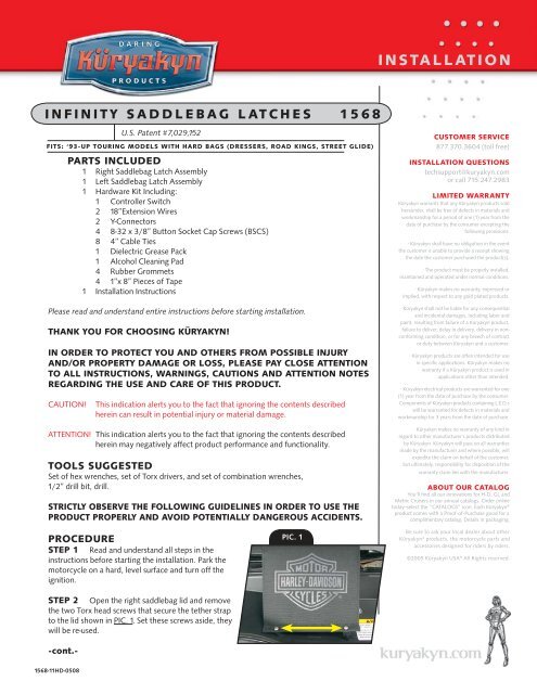
PIC. 1<br />
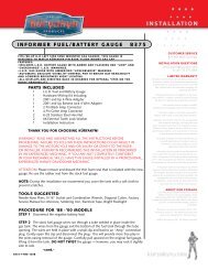
STEP 2 Open the right saddlebag lid and remove<br />
the two Torx head screws that secure the tether strap<br />
to the lid shown in PIC. 1. Set these screws aside, they<br />
will be re-used.<br />
-cont.-<br />
<strong>1568</strong>-11HD-0508
CAUTION!<br />
Avoid damage to the motorcycle. Protect painted surfaces with a soft cloth or blanket.<br />
STEP 3 Note the orientation of the lock and remove the screws that secure it to the latch assembly,<br />
remove the lock and screws, set them aside; they will be reinstalled later. (See PIC. 2)<br />
STEP 4<br />
Remove the nut shown in PIC. 2, this will not be used again.<br />
PIC. 2<br />
STEP 5 Close the lid and hold onto the faceplate while removing the two<br />
Torx screws shown in PIC. 3. One of these screws will be used again.<br />
STEP 6 Slide the wire protector down to the base of the light on the cover<br />
as shown in PIC. 4.<br />
STEP 7 Place the right latch cover on the latch assembly, lining up the<br />
holes; install two of the included 8-32 x 3/8” BHCS screws through the holes<br />
on the outside of the latch cover, do not fully tighten yet.<br />
Lock &<br />
screws<br />
Remove<br />
the nut<br />
(front hole)<br />
STEP 8 Open the lid and install one of the Torx screws that was removed in<br />
STEP 5 in the front hole (shown in PIC. 2). Do not fully tighten the screw at this point.<br />
PIC. 3<br />
STEP 9 Reinstall the lock, making sure to install it in the correct orientation.<br />
Secure with the two screws that were removed in STEP 3.<br />
STEP 10 Making sure the wires are out of the way, fully tighten the screws from<br />
STEP 6, 7 & 8.<br />
STEP 11 Remove the right saddlebag from the motorcycle and place on a soft<br />
clean blanket on a stable surface.<br />
ATTENTION! This procedure requires making permanent modifications to the saddlebag;<br />
this may void your warranty. Consult your dealer for more information.<br />
PIC. 4<br />
STEP 12 Tape the area under the latch at the front of the hinge as shown in PIC. 5 with<br />
masking tape, then mark a location to drill the hole.<br />
Note: It is not necessary to drill a hole in the saddlebag to mount this product. You may<br />
choose to route the wiring in a similar manner to the following steps, except routing the<br />
wires over the top edges of the saddlebag as indicated in PIC. 8.<br />
STEP 13 Make sure that there isn’t anything behind the area where you will be drilling,<br />
and drill a pilot hole using a small drill bit.<br />
STEP 14 Drill a larger hole with a 1/2” drill bit.<br />
STEP 15 Route the wiring as shown in PIC. 6 so that it is behind the wear tab; then insert<br />
the wire through the hole that was drilled in the saddlebag.<br />
Slide wire<br />
protector to<br />
the base of the<br />
lighted cover<br />
PIC. 5<br />
ATTENTION! Secure all wiring away from any moving parts, pinch points or extreme<br />
heat. Küryakyn WILL NOT warranty any electrical component<br />
that fails due to pinched, crimped, broken, abraded, melted or<br />
frayed wires.<br />
STEP 16 Make a small slice in all of the rubber grommets as shown in<br />
PIC. 7, place the grommet over the wire and seat it in the hole in the saddlebag.<br />
STEP 17 Route the wires along the inside of the bag as shown in PIC. 8; do<br />
not tape them to the inside of the saddlebags yet.<br />
Place masking<br />
tape here and<br />
drill a hole<br />
through the<br />
saddlebag<br />
STEP 18 Tape the outside of the bag on the fender side above the front mounting pin hole,<br />
as shown in PIC. 9 and mark the location to drill the hole.<br />
Page<br />
2<br />
-cont.-<br />
infinity saddlebag latches<br />
INSTALLATION
STEP 19 Make sure that there is not anything behind the area where you will be drilling, and drill a<br />
pilot hole using a small drill bit.<br />
STEP 20 Drill a larger hole with a 1/2” drill bit.<br />
STEP 21 Route the wire out through the hole and place a grommet over the<br />
wire and then seat the grommet in the hole in the saddlebag.<br />
PIC. 6<br />
STEP 22 Secure the tether strap to the lid, using the two screws that were<br />
removed in STEP 2.<br />
STEP 23 Repeat STEP 2 through STEP 22 for the left side.<br />
route wires<br />
through the<br />
hole in the<br />
saddlebag<br />
STEP 24 Reinstall the saddlebags on the motorcycle.<br />
STEP 25 Check to make sure that the lid, latch and lock all function<br />
properly and that there is enough slack in the wires so that the latches will<br />
move freely and the wires will not be pinched, stretched or pulled.<br />
Route the<br />
wiring behind<br />
the wear tab<br />
STEP 26 Secure the wires to the inside of the saddlebags as shown with the included tape<br />
from the hardware kit as shown in PIC. 8.<br />
PIC. 7<br />
Note: It may be helpful to cut the tape into smaller pieces.<br />
Wiring<br />
CAUTION!<br />
STEP 1<br />
Do not operate more then 16 Seven Color Lizard Lights on one control switch.<br />
Remove the seat.<br />
Make a slice<br />
in the rubber<br />
grommet<br />
STEP 2 Determine a location on you bike to mount the control switch; clean the area<br />
with the included alcohol cleaning pad and allow the area to dry.<br />
PIC. 8<br />
Note: You may wire the Infinity latch covers into the switch for other<br />
Infinity products or seven-color lizard lights using the included Y-adapters.<br />
The Infinity latches equal a total of 4 lizard lights.<br />
STEP 3 Using the back of your fingernail, rub the adhesive backing on the<br />
switch to activate the catalyst; remove the backing, press and hold the switch<br />
in place for one (1) minute, full bonding strength will occur in 24 hours.<br />
Optional<br />
Route the wires over<br />
the top edges of the<br />
saddlebag if choosing<br />
not to drill holes in<br />
the saddlebag.<br />
ATTENTION! Ensure the area of installation is free of grease, oil, dirt or<br />
other debris to ensure proper adhesion. Küryakyn WILL<br />
NOT warranty any parts lost due to improper installation.<br />
PIC. 9<br />
ATTENTION! The adhesive will not bond correctly if applied at<br />
temperatures less than 50° F. Do not attempt this<br />
installation in temperatures less than 50° F.<br />
STEP 4 The black wire from the switch is a ground wire and needs to be secured to the<br />
negative terminal on the battery or other grounding location.<br />
STEP 5 The red wire from the switch (with in-line fuse) is a power wire and needs to be<br />
secured to the positive terminal on the battery.<br />
STEP 6 Apply a small amount of dielectric grease to the connections and plug<br />
the wiring harness from the saddlebag latch covers cover into the harness from the switch making<br />
sure that the red wires from the cover lines up with the red wire from the switch.<br />
Note: Use the included extensions as needed.<br />
Page<br />
3<br />
Tape and mark a the<br />
location to drill the<br />
hole above the front<br />
mounting hole<br />
-cont.-<br />
infinity saddlebag latches<br />
INSTALLATION
ATTENTION! Küryakyn recommends the use of dielectric grease on electrical connections.<br />
STEP 7 Secure all wiring away from heat sources and or moving parts using the included cable<br />
ties. Melted wire insulation may result in a short circuit.<br />
ATTENTION! Secure all wiring away from any moving parts, pinch points or extreme heat. Küryakyn<br />
WILL NOT warranty any electrical component that fails due to pinched, crimped, broken,<br />
abraded, melted or frayed wires.<br />
STEP 8<br />
Reinstall the seat.<br />
ATTENTION! It is the installer’s responsibility to ensure that all of the fasteners (including<br />
pre-assembled) are tightened before operation of the motorcycle. Küryakyn will<br />
not warranty components lost due to improper installation. Periodic maintenance may<br />
be required.<br />
OPERATION<br />
The controller has a rheostat, a toggle switch, and a push button.<br />
• Use the toggle switch to select “STEADY ON” or “FLASH” modes or to turn the<br />
lights “OFF”.<br />
• The push button allows the user to select the color they wish to illuminate. There are<br />
eight possibilities. The first seven options select an individual color. The eighth option is<br />
called “PAINT MODE” which continuously cycles the lights through all seven colors and<br />
is indicated by the white-colored light to initiate the Paint Mode.<br />
• The rheostat varies the flash rate when illuminating a specific color in “FLASH” mode<br />
or varies the rate at which the lights cycle through all seven colors if “PAINT MODE”<br />
is selected.<br />
Ride On!<br />
Page<br />
4<br />
infinity saddlebag latches<br />
INSTALLATION