INfINITY SADDLEBAG LATChES 1568
INfINITY SADDLEBAG LATChES 1568
INfINITY SADDLEBAG LATChES 1568

You also want an ePaper? Increase the reach of your titles
YUMPU automatically turns print PDFs into web optimized ePapers that Google loves.
CAUTION!<br />
Avoid damage to the motorcycle. Protect painted surfaces with a soft cloth or blanket.<br />
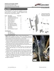
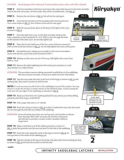
STEP 3 Note the orientation of the lock and remove the screws that secure it to the latch assembly,<br />
remove the lock and screws, set them aside; they will be reinstalled later. (See PIC. 2)<br />
STEP 4<br />
Remove the nut shown in PIC. 2, this will not be used again.<br />
PIC. 2<br />
STEP 5 Close the lid and hold onto the faceplate while removing the two<br />
Torx screws shown in PIC. 3. One of these screws will be used again.<br />
STEP 6 Slide the wire protector down to the base of the light on the cover<br />
as shown in PIC. 4.<br />
STEP 7 Place the right latch cover on the latch assembly, lining up the<br />
holes; install two of the included 8-32 x 3/8” BHCS screws through the holes<br />
on the outside of the latch cover, do not fully tighten yet.<br />
Lock &<br />
screws<br />
Remove<br />
the nut<br />
(front hole)<br />
STEP 8 Open the lid and install one of the Torx screws that was removed in<br />
STEP 5 in the front hole (shown in PIC. 2). Do not fully tighten the screw at this point.<br />
PIC. 3<br />
STEP 9 Reinstall the lock, making sure to install it in the correct orientation.<br />
Secure with the two screws that were removed in STEP 3.<br />
STEP 10 Making sure the wires are out of the way, fully tighten the screws from<br />
STEP 6, 7 & 8.<br />
STEP 11 Remove the right saddlebag from the motorcycle and place on a soft<br />
clean blanket on a stable surface.<br />
ATTENTION! This procedure requires making permanent modifications to the saddlebag;<br />
this may void your warranty. Consult your dealer for more information.<br />
PIC. 4<br />
STEP 12 Tape the area under the latch at the front of the hinge as shown in PIC. 5 with<br />
masking tape, then mark a location to drill the hole.<br />
Note: It is not necessary to drill a hole in the saddlebag to mount this product. You may<br />
choose to route the wiring in a similar manner to the following steps, except routing the<br />
wires over the top edges of the saddlebag as indicated in PIC. 8.<br />
STEP 13 Make sure that there isn’t anything behind the area where you will be drilling,<br />
and drill a pilot hole using a small drill bit.<br />
STEP 14 Drill a larger hole with a 1/2” drill bit.<br />
STEP 15 Route the wiring as shown in PIC. 6 so that it is behind the wear tab; then insert<br />
the wire through the hole that was drilled in the saddlebag.<br />
Slide wire<br />
protector to<br />
the base of the<br />
lighted cover<br />
PIC. 5<br />
ATTENTION! Secure all wiring away from any moving parts, pinch points or extreme<br />
heat. Küryakyn WILL NOT warranty any electrical component<br />
that fails due to pinched, crimped, broken, abraded, melted or<br />
frayed wires.<br />
STEP 16 Make a small slice in all of the rubber grommets as shown in<br />
PIC. 7, place the grommet over the wire and seat it in the hole in the saddlebag.<br />
STEP 17 Route the wires along the inside of the bag as shown in PIC. 8; do<br />
not tape them to the inside of the saddlebags yet.<br />
Place masking<br />
tape here and<br />
drill a hole<br />
through the<br />
saddlebag<br />
STEP 18 Tape the outside of the bag on the fender side above the front mounting pin hole,<br />
as shown in PIC. 9 and mark the location to drill the hole.<br />
Page<br />
2<br />
-cont.-<br />
infinity saddlebag latches<br />
INSTALLATION