Motor Protection Principles.pdf
Motor Protection Principles.pdf
Motor Protection Principles.pdf
Create successful ePaper yourself
Turn your PDF publications into a flip-book with our unique Google optimized e-Paper software.
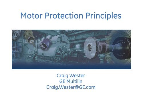
<strong>Motor</strong> <strong>Protection</strong> <strong>Principles</strong><br />
Craig Wester<br />
GE Multilin<br />
Craig.Wester@GE.com
<strong>Motor</strong> History & Facts<br />
• The first U.S. patent for a motor<br />
was issued to Thomas Davenport in<br />
1837.<br />
• Today in North America, more<br />
than 1 billion motors are in<br />
service.<br />
• <strong>Motor</strong>s consume 25% of<br />
electricity in North America.<br />
• In 1888, Nikola Tesla patented the<br />
first AC poly-phase motor.<br />
• Electricity consumption by motors<br />
in manufacturing sector is 70%.<br />
In oil, gas and mining industries<br />
around 90%.<br />
• Three phase squirrel-cage<br />
induction motors account for over<br />
90% of the installed motor<br />
capacity.<br />
2
Various Industry <strong>Motor</strong> Applications<br />
• Fans, Blowers<br />
• Pumps, Compressors<br />
• Grinders, Chippers<br />
• Conveyors, Shredders<br />
• Crushers, Mixers<br />
• Cranes, Extruders<br />
• Refiners, Chillers<br />
3
<strong>Motor</strong> Failure Rates and Cost<br />
• <strong>Motor</strong> failure rate is<br />
conservatively estimated as<br />
3-5% per year<br />
• In Mining, Pulp and Paper<br />
industry, motor failure rate<br />
can be as high as 12%.<br />
• <strong>Motor</strong> failures divided in 3<br />
groups:<br />
• Electrical (33%)<br />
• Mechanical (31%)<br />
• Environmental,<br />
Maintenance, & Other (36%)<br />
• <strong>Motor</strong> failure cost<br />
contributors:<br />
• Repair or Replacement<br />
• Removal and Installation<br />
• Loss of Production<br />
IEEE STUDY<br />
EPRI STUDY<br />
AVERAGE<br />
FAILURE CONTRIBUTOR % FAILED COMPONENT % %<br />
Persistent Overload 4.20% Stator Ground Insulation 23.00<br />
Electrical<br />
Normal Deterioration 26.40% Turn Insulation 4.00<br />
Related Failures<br />
Bracing 3.00<br />
Core 1.00<br />
Cage 5.00 33%<br />
Electrical Related Total 30.60% Electrical Related Total 36.00%<br />
High Vibration 15.50% Sleeve Bearings 16.00<br />
Mechanical<br />
Poor Lubrication 15.20% Antifriction Bearings 8.00<br />
Related Failures<br />
Trust Bearings 5.00<br />
Rotor Shaft 2.00<br />
Rotor Core 1.00<br />
31%<br />
Mechanical Related<br />
Mechanical Related<br />
30.70% 32.00%<br />
Total<br />
Total<br />
High Ambient Temp. 3 Bearing Seals 6.00<br />
Abnormal Moisture 5.8 Oil Leakege 3.00 Environmental,<br />
Maintanence &<br />
Abnormal Voltage 1.5 Frame 1.00<br />
Other Reasons<br />
Abnormal Frequency 0.6 Wedges 1.00 Related Failures<br />
Abrasive Chemicals 4.2<br />
Poor Ventilation Cooling 3.9<br />
Other Reasons 19.7 Other Components 21.00<br />
Environmental Related &<br />
Other Reasons: Total<br />
38.70%<br />
Maintanence Related &<br />
Other Parts: Total<br />
32.00%<br />
36%<br />
Harsh Conformal Coating Can Reduce<br />
Environmental Failures<br />
4
Thermal Stress Causes <strong>Motor</strong> Failure<br />
• Most of the motor failure contributors and failed motor components are<br />
related to motor overheating.<br />
• Thermal stress potentially can cause the failure of all the major motor parts:<br />
Stator, Rotor, Bearings, Shaft and Frame.<br />
5
Risks for an Overheated <strong>Motor</strong><br />
• Stator Windings Insulation Degradation (for stator limited motors)<br />
Insulation lifetime decreases by half if motor operating temperature<br />
exceeds thermal limit by 10ºC for any period of time<br />
110<br />
PERCENTAGE OF LIFE (%)<br />
100<br />
90<br />
80<br />
70<br />
60<br />
50<br />
40<br />
30<br />
20<br />
10<br />
A-CLASS (105 ºC)<br />
B-CLASS (130ºC)<br />
F-CLASS (155 ºC)<br />
H-CLASS (180 ºC)<br />
A B F H<br />
For F class<br />
insulation, stator<br />
temperature of<br />
165ºC causes motor<br />
lifetime to decrease<br />
to 50%<br />
0<br />
0 50 100 150 200 250 300<br />
TEMPERATURE (ºC)<br />
• Rotor Conductors Deforming or Melting (for rotor limited - thermal limit is<br />
defined by motor stall time)<br />
6
<strong>Motor</strong> Electrical <strong>Protection</strong><br />
• Thermal Overload<br />
• Process Caused (Excessive load)<br />
• High Ambient Conditions (Hot, Blocked Ventilation)<br />
• Power Supply Issues (Voltage/Current Unbalance, Harmonics)<br />
• Phase Fault<br />
• Ground Fault<br />
• Abnormal Operating Conditions<br />
• Over & Under Voltage<br />
• Underfrequency<br />
• Voltage and Current Unbalance<br />
• Load Loss<br />
• Jamming<br />
• Jogging<br />
7
Overload <strong>Protection</strong> - Thermal Model<br />
A motor can run overloaded without a fault in motor or supply<br />
A primary motor protective element of the motor protection relay is the<br />
thermal overload element and this is accomplished through motor<br />
thermal image modeling. This model must account for thermal process<br />
in the motor while motor is starting, running at normal load, running<br />
overloaded and stopped. Algorithm of the thermal model integrates<br />
both stator and rotor heating into a single model.<br />
• Main Factors and Elements Comprising<br />
the Thermal Model are:<br />
• Overload Pickup Level<br />
• Overload Curve<br />
• Running & Stopped Cooling Time Constants<br />
• Hot/Cold Stall Time Ratio<br />
• RTD & Unbalance Biasing<br />
• <strong>Motor</strong> State Machine<br />
8
Thermal Model - <strong>Motor</strong> States<br />
• <strong>Motor</strong> Stopped:<br />
Current < “0” threshold & contactor/breaker is open.<br />
• <strong>Motor</strong> Starting:<br />
Previous state is “Stopped” & Current > “0” threshold. <strong>Motor</strong> current<br />
must increase to the level higher than overload pickup within<br />
seconds.<br />
• <strong>Motor</strong> Running:<br />
Previous state is “Starting” or “Overloading” & Current drops below<br />
overload pickup level.<br />
• <strong>Motor</strong> Overloading:<br />
Previous state is “Running” & Current raises above overload pickup<br />
level. Thermal Capacity Used (TCU) begins to accumulate during<br />
overload.<br />
9
<strong>Motor</strong> Thermal Limit Curves<br />
• Thermal Limit of the model is dictated by overload curve<br />
constructed in the motor protection device in reference to thermal<br />
damage curves normally supplied by motor manufacturer.<br />
• <strong>Motor</strong> protection device is equipped with set of standard curves<br />
and capable to construct customized curves for any motor<br />
application.<br />
Thermal Limit Curves:<br />
B<br />
A<br />
D<br />
C<br />
A. Cold Running Overload<br />
B. Hot Running Overload<br />
C. Cold Locked Rotor Curve<br />
D. Hot Locked Rotor Curve<br />
E<br />
F<br />
E. Acceleration curve @ 80% rated<br />
voltage<br />
F. Acceleration curve @100%<br />
voltage<br />
10
Thermal Overload Pickup<br />
• Set to the maximum allowed by the<br />
service factor of the motor.<br />
• Set slightly above the motor service<br />
factor by 8-10% to account for<br />
measuring errors<br />
• If RTD Biasing of Thermal Model is<br />
used, thermal overload setting can<br />
be set higher<br />
• Note: motor feeder cables are<br />
normally sized at 1.25 times motor’s<br />
full load current rating, which would<br />
limit the motor overload pickup<br />
setting to a maximum of 125%.<br />
SF Thermal Overload Pickup<br />
1.0 1.1<br />
1.15 1.25<br />
11
Thermal Model – Thermal Capacity Used<br />
• Thermal Capacity Used (TCU) is a criterion selected in thermal<br />
model to evaluate thermal condition of the motor.<br />
• TCU is defined as percentage of motor thermal limit utilized during<br />
motor operation.<br />
• A running motor will have some level of thermal capacity used due<br />
to <strong>Motor</strong> Losses.<br />
• Thermal Overload Trip when Thermal Capacity Used equals 100%<br />
12
Overload Curve Selection for Thermal Model<br />
Overload Curve<br />
Set the overload curve below cold thermal limit and above hot thermal limit<br />
If only hot curve is provided by mfgr, then must set at or below hot thermal limit<br />
13
Thermal Model–Hot/Cold Stall Time Ratio (HCR)<br />
• Typically motor manufacturer provides the values of the locked rotor<br />
thermal limits for 2 motor conditions:<br />
• COLD : motor @ ambient temperature<br />
• HOT : motor @ rated temperature for specific class and service factor.<br />
• NEMA standard temperature rises for motors up to 1500HP and Service<br />
Factors 1 and 1.15 respectively.<br />
AMBIENT CLASS A CLASS B CLASS F CLASS H<br />
• When motor is running below overload pickup, the TCU will rise or fall to value<br />
based on average current and HCR. HCR is used to calculate level of TCU by<br />
relay, at which motor will settle for current below overload pickup.<br />
14
Hot/Cold Safe Stall Ratio<br />
HCR =<br />
LRT<br />
LRT<br />
HOT<br />
COLD<br />
Hot/Cold Ratio =<br />
30/35<br />
=> 0.86<br />
Overload Curve Method<br />
• If the thermal limits curves are being used to<br />
determine the HOT/COLD ratio proceed as follows:<br />
LRTcold = 8sec<br />
LRThot = 6sec<br />
LRC = 5.4FLA<br />
• From the thermal limits curves run a line<br />
perpendicular to the current axis that intersects the<br />
hot and cold curves at the stall point or LRA<br />
• The Hot/cold ratio can now be calculated as follows:<br />
= 6s/8s = 0.75<br />
• If hot and cold times are not provided and only one<br />
curve is given verify with the manufacturer that it is<br />
the hot curve ( which is the worst case), then the<br />
Hot/ Cold ratio should be set to 1.0<br />
15
Overload Curve Selection<br />
If the motor starting current<br />
begins to infringe on the<br />
thermal damage curves or if<br />
the motor is called upon to<br />
drive a high inertia load such<br />
that the acceleration time<br />
exceeds the safe stall time,<br />
custom or voltage<br />
dependent overload curve<br />
may be required.<br />
16
Overload Curve Selection<br />
A custom overload curve will<br />
allow the user to tailor the<br />
relay’s thermal damage<br />
curve to the motor such that<br />
a successful start can occur<br />
without compromising<br />
protection while at the same<br />
time utilizing the motor to its<br />
full potential during the<br />
running condition.<br />
17
Thermal Model Behavior - Long Starts<br />
• Issue Duration of a high inertia load start is longer than the allowed<br />
motor safe stall time.<br />
• For these starts, thermal model must account for the current change during<br />
acceleration and also use the acceleration thermal limits for TCU calculations.<br />
• <strong>Motor</strong> thermal limit is growing along with motor rotation speed during<br />
acceleration.<br />
• Starting current is proportional to system voltage during motor acceleration,<br />
thus voltage could be a good indication of the current level corresponding to the<br />
locked rotor conditions.<br />
• Voltage dependant dynamic thermal limit curve is employed to enhance the<br />
thermal model algorithm.<br />
• <strong>Motor</strong> relay will shift acceleration<br />
thermal limit curve linearly<br />
and constantly based on<br />
measured line voltage during<br />
a motor start.<br />
18
Thermal Model - Current Unbalance Bias<br />
Negative sequence currents (or unbalanced phase currents) will<br />
cause additional rotor heating that will be accounted for in Thermal<br />
Model.<br />
Positive Sequence<br />
• Main causes of current unbalance<br />
• Blown fuses<br />
• Loose connections<br />
• Stator turn-to-turn faults<br />
• System voltage distortion and unbalance<br />
• Faults<br />
Negative Sequence<br />
19
Thermal Model - Current Unbalance Bias<br />
• Equivalent heating motor current is employed to bias thermal<br />
model in response to current unbalance.<br />
2<br />
IEQ = IM<br />
× (1 + K × (I<br />
2<br />
I<br />
1<br />
)<br />
2<br />
)<br />
• Im - real motor current; K - unbalance bias factor; I 1 & I 2 - positive<br />
and negative sequence components of motor current.<br />
• K factor reflects the degree of extra heating caused by the negative<br />
sequence component of the motor current.<br />
• IEEE guidelines for typical and conservative estimates of K.<br />
K = 175<br />
2<br />
I LRC<br />
TYPICAL<br />
K = 230<br />
2<br />
I LRC<br />
CONSERVATIVE<br />
20
Thermal Model – RTD Bias<br />
• Accelerate thermal trip for<br />
hot stator windings<br />
• RTD bias model determines the<br />
Thermal Capacity Used based on the<br />
temperature of the Stator and is<br />
separate from the overload model for<br />
calculating Thermal Capacity Used.<br />
• <strong>Motor</strong> relay will use the calculated<br />
thermal capacity unless the RTD<br />
thermal capacity is higher.<br />
• This function will not trip the motor at<br />
the max point temp unless the average<br />
current is greater than the overload<br />
pickup setting<br />
• RTD biasing is a back up protection<br />
element which accounts for such things<br />
as loss of cooling or unusually high<br />
ambient temperature.<br />
21
Thermal Model - <strong>Motor</strong> Cooling<br />
• <strong>Motor</strong> cooling is characterized by separate cooling time constants<br />
(CTC) for running and stopped motor states. Typical ratio of the<br />
stopped to running CTC is 2/1<br />
• It takes the motor typically 5 time constants to cool.<br />
Thermal Model Cooling <strong>Motor</strong> Tripped<br />
Thermal Model Cooling100% load - Running<br />
22
Overvoltage <strong>Protection</strong><br />
• The overall result of an overvoltage condition is a decrease<br />
in load current and poor power factor.<br />
• Although old motors had robust design, new motors are<br />
designed close to saturation point for better utilization of<br />
core materials and increasing the V/Hz ratio cause<br />
saturation of air gap flux leading to motor heating.<br />
• The overvoltage element should be set to 110% of the<br />
motors nameplate unless otherwise started in the data<br />
sheets.<br />
23
Undervoltage <strong>Protection</strong><br />
• The overall result of an undervoltage condition is an increase in current<br />
and motor heating and a reduction in overall motor performance.<br />
• The undervoltage protection element can be thought of as backup<br />
protection for the thermal overload element. In some cases, if an<br />
undervoltage condition exists it may be desirable to trip the motor faster<br />
than thermal overload element.<br />
• The undervoltage trip should be set to 80-90% of nameplate unless<br />
otherwise stated on the motor data sheets.<br />
• <strong>Motor</strong>s that are connected to the same source/bus may experience a<br />
temporary undervoltage, when one of motors starts. To override this<br />
temporary voltage sags, a time delay setpoint should be set greater than<br />
the motor starting time.<br />
24
Unbalance <strong>Protection</strong><br />
• Indication of unbalance negative sequence current / voltage<br />
• Unbalance causes motor stress and temperature rise<br />
• Current unbalance in a motor is result of unequal line voltages<br />
• Unbalanced supply, blown fuse, single-phasing<br />
• Current unbalance can also be present due to:<br />
• Loose or bad connections<br />
• Incorrect phase rotation connection<br />
• Stator turn-to-turn faults<br />
<strong>Motor</strong> Relay<br />
• For a typical three-phase induction motor:<br />
• 1% voltage unbalance (V2) relates to 6% current unbalance (I2)<br />
• For small and medium sized motors, only current transformers (CTs) are available<br />
and no voltage transformers (VTs). Measure current unbalance and protect motor.<br />
• The heating effect caused by current unbalance will be protected by enabling the<br />
unbalance input to the thermal model<br />
• For example, a setting of 10-15% x FLA for the current unbalance alarm with a<br />
delay of 5-10 seconds and a trip level setting of 20-25% x FLA for the current<br />
unbalance trip with a delay of 2-5 seconds would be appropriate.<br />
25
Ground Fault <strong>Protection</strong><br />
• A ground fault is a fault that creates a path<br />
for current to flow from one of the phases<br />
directly to the neutral through the earth<br />
bypassing the load<br />
• Ground faults in a motor occur:<br />
• When its phase conductor’s insulation is<br />
damaged for example due to voltage stress,<br />
moisture or internal fault occurs between the<br />
conductor and ground<br />
• To limit the level of the ground fault current<br />
connect an impedance between the<br />
supplies neutral and ground. This<br />
impedance can be in the form of a resistor<br />
or grounding transformer sized to ensure<br />
maximum ground fault current is limited.<br />
26
Ground Fault <strong>Protection</strong><br />
Zero Sequence CT Connection<br />
• Best method<br />
• Most sensitive & inherent noise immunity<br />
• All phase conductors are passed through the window of the same CT referred to<br />
as the zero sequence CT<br />
• Under normal circumstances, the three phase currents will sum to zero<br />
resulting in an output of zero from the Zero Sequence CT’s secondary.<br />
• If one of the motors phases were to shorted to ground, the sum of the phase<br />
currents would no longer equal zero causing a current to flow in the secondary<br />
of the zero sequence. This current would be detected by the motor relay as a<br />
ground fault.<br />
27
Ground Fault <strong>Protection</strong><br />
Residual Ground Fault Connection<br />
• Less sensitive<br />
• Drawbacks due to asymmetrical starting<br />
current and un-matched CTs<br />
• For large cables that cannot be fit through the zero sequence CT’s window, the<br />
residual ground fault configuration can be used.<br />
• This configuration is inherently less sensitive than that of the zero sequence<br />
configuration owing to the fact that the CTs are not perfectly matched.<br />
• During motor starting, the motor’s phase currents typically rise to magnitudes<br />
excess of 6 times motors full load current and are asymmetrical.<br />
• The combination of non perfectly matched CTs and relative large phase current<br />
magnitudes produce a false residual current. This current will be<br />
misinterpreted by the motor relay as a ground fault unless the ground fault<br />
element’s pickup is set high enough to disregard this error during starting<br />
28
Differential <strong>Protection</strong><br />
• Differential protection may be considered the first line of protection<br />
for internal phase-to-phase or phase-to-ground faults. In the event<br />
of such faults, the quick response of the differential element may<br />
limit the damage that may have otherwise occurred to the motor.<br />
Core balance method:<br />
• Two sets of CT’s, one at the beginning of<br />
the motor feeder, and the other at the<br />
neutral point<br />
• Alternatively, one set of three core-balance<br />
CTs can also be used<br />
• The differential element subtracts the<br />
current coming out of each phase from the<br />
current going into each phase and<br />
compares the result or difference with the<br />
differential pickup level.<br />
29
Differential <strong>Protection</strong><br />
Summation method with six CTs:<br />
• If six CTs are used in a summing<br />
configuration, during motor starting, the<br />
values from the two CTs on each phase<br />
may not be equal as the CTs are not<br />
perfectly identical and asymmetrical<br />
currents may cause the CTs on each phase<br />
to have different outputs.<br />
• To prevent nuisance tripping in this<br />
configuration, the differential level may<br />
have to be set less sensitive, or the<br />
differential time delay may have to be<br />
extended to ride through the problem<br />
period during motor starting.<br />
• The running differential delay can then be<br />
fine tuned to an application such that it<br />
responds very fast and is sensitive to low<br />
differential current levels.<br />
30
Differential <strong>Protection</strong><br />
Biased differential protection - six CTs:<br />
• Biased differential protection method allows<br />
for different ratios for system/line and the<br />
neutral CT’s.<br />
• This method has a dual slope characteristic.<br />
Main purpose of the percent-slope<br />
characteristic is to prevent a mis-operation<br />
caused by unbalances between CTs during<br />
external faults. CT unbalances arise as a<br />
result of CT accuracy errors or CT saturation.<br />
• Characteristic allows for very sensitive<br />
settings when the fault current is low and less<br />
sensitive settings when the fault current is<br />
high and CT performance may produce<br />
incorrect operating signals.<br />
31
Short Circuit <strong>Protection</strong><br />
• The short circuit element provides protection<br />
for excessively high overcurrent faults<br />
• Phase-to-phase and phase-to-ground faults<br />
are common types of short circuits<br />
• When a motor starts, the starting current<br />
(which is typically 6 times the Full Load<br />
Current) has asymmetrical components .<br />
These asymmetrical currents may cause one<br />
phase to see as much as 1.7 times the RMS<br />
starting current.<br />
• To avoid nuisance tripping during starting,<br />
set the the short circuit protection pick up to<br />
a value at least 1.7 times the maximum<br />
expected symmetrical starting current of<br />
motor.<br />
• The breaker or contactor must have an<br />
interrupting capacity equal to or greater then<br />
the maximum available fault current or let an<br />
upstream protective device interrupt fault<br />
current.<br />
32
Stator RTD <strong>Protection</strong><br />
• A simple method to determine the heating<br />
within the motor is to monitor the stator with<br />
RTDs.<br />
• Stator RTD trip level should be set at or below<br />
the maximum temperature rating of the<br />
insulation.<br />
• For example, a motor with class F insulation<br />
that has a temperature rating of 155°C could<br />
have the Stator RTD Trip level be set between<br />
140°C to 145°C, with 145° C being the<br />
maximum (155°C - 10°C hot spot)<br />
• The stator RTD alarm level could be set to a<br />
level to provide a warning that the motor<br />
temperature is rising<br />
33
Additional <strong>Protection</strong> Methods<br />
•Start Inhibit<br />
This function will limit starts when the motor is already hot.<br />
•Starts/Hour<br />
• Time Between Starts (Jogging)<br />
• Bearing RTD <strong>Protection</strong><br />
• Acceleration Trip<br />
Set higher than the maximum starting time to avoid nuisance<br />
tripping when the voltage is lower or for varying loads during<br />
acceleration.<br />
34
Conclusions<br />
• Induction & synchronous motors are valuable assets to<br />
today’s industrial facilities.<br />
• The temperature rise of motor dictates its life<br />
• When applied, thermal protection can prevent loss of motor<br />
life<br />
• Additional protection elements such as overvoltage,<br />
undervoltage, unbalance, ground fault, differential, short<br />
circuit and stator RTD supplement the thermal model<br />
protection and provide complete motor protection.<br />
• Harsh conformal coating of motor protection relays should<br />
be considered to avoid the environmental effects of harsh<br />
gaseous sulphides (H2S, etc.)<br />
35


