LIGO-P030036-00-R - Ligo - Caltech
LIGO-P030036-00-R - Ligo - Caltech
LIGO-P030036-00-R - Ligo - Caltech

Create successful ePaper yourself
Turn your PDF publications into a flip-book with our unique Google optimized e-Paper software.
HARRY, HOUSER, AND STRAIN PHYSICAL REVIEW D 65 082<strong>00</strong>1<br />
were modeled in aluminum and the transducer mass was<br />
modeled in niobium. Each of the mechanical Q’s was modeled<br />
as 4010 6 27–29. Depending on the design of the<br />
transducer, the final Q can be degraded by the addition of<br />
loss from electrical coupling to the SQUID circuit 30. The<br />
sphere’s thermal noise is shown in Fig. 2 graphed as a strain<br />
spectrum.<br />
All of the noise sources for the sphere were then combined<br />
to determine the total noise<br />
S tot f S u f S f , out f S sph,therm .<br />
9<br />
This total noise is shown, along with each component, in Fig.<br />
2 graphed as a strain spectrum.<br />
The gravitational wave signal is applied as force on the<br />
spherical antenna, but is read out as velocity of the transducer<br />
mass. Thus, before a signal can be compared to these<br />
noise sources, the gravitational strain must be converted to a<br />
force and be passed through the admittance matrix of the<br />
sphere-transducer system. The comparable signal can be<br />
written 2<br />
f Y 5/2 m s<br />
f 0 3 3/2 f 2 y 21 f h f 2 , 10<br />
where Y is Young’s modulus for the sphere material, is the<br />
density of the sphere material, is the reduced cross section<br />
of the sphere and equals 0.215 for the lowest quadrupole<br />
mode 25, h( f ) is the frequency-domain amplitude of the<br />
gravitational wave, and the admittance matrix element y 21 ( f )<br />
can be written<br />
y 21 f 8 3 f 3 ic 2 c s m 2 /„14 2 f 2 c 2 m 2 4 2 f 2 c s m 1<br />
m 2 m s 4 2 f 2 c 2 m 1 m 2 4 2 f 2 c 2 m 2 m s …<br />
4 2 f 2 c 1 14 2 f 2 c s m s „m 2 m 1 1<br />
4 2 f 2 c 2 m 2 ….<br />
11<br />
Table I shows all the parameters used in the sphere model.<br />
The interferometer was modeled using a slightly modified<br />
version of the BENCH program 31. BENCH version 1.11 was<br />
the basis of our model, but it was ported to MATHEMATICA<br />
from MATLAB and a few noise formulas were updated. The<br />
factors of two errors in the thermal noise in BENCH 1.11 were<br />
fixed. The equations presented below are the ones used in<br />
our model.<br />
The noise in the interferometer is dominated by three<br />
types of noise; seismic, thermal, and optical readout noise.<br />
Each noise source was modeled using parameters from the<br />
advanced <strong>LIGO</strong> white paper 32, which is scheduled to be<br />
implemented in 2<strong>00</strong>5. The corresponding advanced interferometer<br />
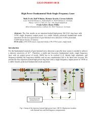
is scheduled to begin taking data in 2<strong>00</strong>7. A schematic<br />
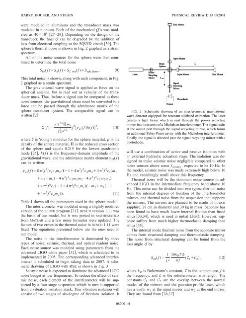
drawing of <strong>LIGO</strong> with RSE is shown in Fig. 3<br />
Seismic noise is expected to dominate the advanced <strong>LIGO</strong><br />
noise budget at low frequencies. To reduce the effect of seismic<br />
noise, each element of the interferometer will be supported<br />
by a four-stage suspension which in turn is supported<br />
from a vibration isolation stack. This vibration isolation will<br />
consist of two stages of six-degree of freedom isolation. It<br />
FIG. 3. Schematic drawing of an interferometric gravitational<br />
wave detector equipped for resonant sideband extraction. The laser<br />
creates a light beam which is sent through the power recycling<br />
mirror into two arms of a Michelson interferometer. The signal exits<br />
at the output port through the signal recycling mirror, which forms<br />
an additional Fabry-Pérot cavity with the Michelson interferometer.<br />
Finally, the signal is detected past the signal recycling mirror with a<br />
photodiode.<br />
will use a combination of active and passive isolation with<br />
an external hydraulic actuation stage. The isolation was designed<br />
to make seismic noise negligible compared to other<br />
noise sources above some f seismic , expected to be 10 Hz. In<br />
the model, seismic noise was made extremely high below 10<br />
Hz and vanishingly small above this frequency.<br />
Thermal noise will be the dominant noise source in advanced<br />
<strong>LIGO</strong> in the intermediate frequency band above 10<br />
Hz. This noise can be divided into two types; thermal noise<br />
from the internal degrees of freedom of the interferometer<br />
mirrors, and thermal noise from the suspension that supports<br />
the mirrors. The mirrors are planned to be made of m-axis<br />
sapphire, 28 cm in diameter and 30 kg in mass. Sapphire has<br />
been found to have much lower internal friction than fused<br />
silica 33,34, which is used in initial <strong>LIGO</strong>. However, sapphire<br />
suffers from much higher thermoelastic damping than<br />
silica 35.<br />
The internal mode thermal noise from the sapphire mirror<br />
comes from structural damping and thermoelastic damping.<br />
The noise from structural damping can be found from the<br />
loss angle by<br />
S str f 1 16k B T<br />
C<br />
L 2 f 1 C 2 ,<br />
12<br />
where k B is Boltzmann’s constant, T is the temperature, f is<br />
the frequency, and L is the interferometer arm length. The<br />
constants C 1 and C 2 are the overlap between the normal<br />
modes of the mirrors and the gaussian-profile laser, which<br />
has a width w 1 at the input mirror and w 2 at the end mirror.<br />
They are found from 36,37<br />
082<strong>00</strong>1-4