Orion: America's Next Generation Spacecraft (4.7 Mb PDF) - NASA
Orion: America's Next Generation Spacecraft (4.7 Mb PDF) - NASA
Orion: America's Next Generation Spacecraft (4.7 Mb PDF) - NASA

Create successful ePaper yourself
Turn your PDF publications into a flip-book with our unique Google optimized e-Paper software.
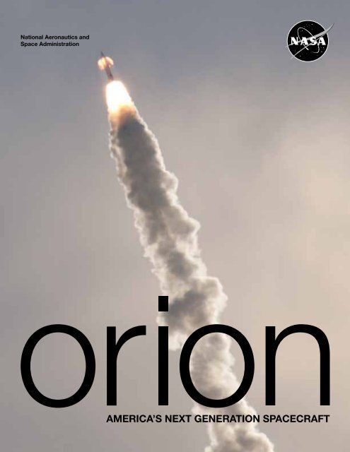
National Aeronautics and<br />
Space Administration<br />
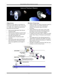
AMERICA’S NEXT GENERATION SPACECRAFT
INSIDE:<br />
LEADING EDGE DESIGN AND ENGINEERING<br />
TECHNOLOGY INNOVATION<br />
BUILDING ORION<br />
TESTING ORION<br />
INVESTING IN OUR FUTURE<br />
LEADING EDGE DESIGN AND ENGINEERING<br />
Drawing from more than 50 years of spaceflight<br />
research and development, <strong>Orion</strong> is designed to meet<br />
the evolving needs of our nation’s space program for<br />
decades to come.<br />
As the flagship of our nation’s next-generation space<br />
fleet, <strong>Orion</strong> will push the envelope of human spaceflight<br />
far beyond low Earth orbit.<br />
<strong>Orion</strong> may resemble its Apollo-era predecessors, but<br />
its technology and capability are light years apart.<br />
<strong>Orion</strong> features dozens of technology advancements<br />
and innovations that have been incorporated into the<br />
spacecraft’s subsystem and component design.<br />
To support long-duration deep space missions of up<br />
to six months, <strong>Orion</strong> engineers developed a state-ofthe-art<br />
spacecraft with unique life support, propulsion,<br />
thermal protection and avionics systems.<br />
Building upon the best of Apollo and shuttle-era design,<br />
the <strong>Orion</strong> spacecraft includes both crew and service<br />
modules, a spacecraft adaptor, and a revolutionary<br />
launch abort system that will significantly increase<br />
crew safety.<br />
<strong>Orion</strong>’s crew module is much larger than Apollo’s and<br />
can support more crew members for short or longduration<br />
spaceflight missions. The service module is<br />
the powerhouse that fuels and propels the spacecraft<br />
as well as the storehouse for the life-sustaining air and<br />
water astronauts need during their space travels. The<br />
service module’s structure will also provide places to<br />
mount scientific experiments and cargo.<br />
<strong>Orion</strong> is capable of supporting low Earth orbit missions<br />
or transporting astronauts on a variety of expeditions<br />
beyond low Earth orbit – ushering in a new era of<br />
space exploration. <strong>Orion</strong> can carry astronauts to the<br />
International Space Station, deliver cargo for resupply,<br />
and remain on orbit under its own power supply to serve<br />
as an emergency escape vehicle for the crew onboard.
ORION<br />
CREW EXPLORATION<br />
VEHICLE<br />
Attitude Control<br />
Motor<br />
Jettison Motor<br />
Abort<br />
Motor<br />
Launch Abort System<br />
Fillet<br />
Ogive<br />
Fairing<br />
Docking Adapter<br />
Crew Module<br />
Roll Control<br />
Thrusters<br />
Service Module<br />
CM/SM Umbilical<br />
Solar Array<br />
Auxiliary<br />
Thrusters<br />
<strong>Spacecraft</strong> Adapter<br />
Orbital<br />
Maneuvering<br />
Engine
The test vehicle is<br />
readied for launch at<br />
White Sands Missile<br />
Range’s Launch<br />
Complex 32E.<br />
The launch abort system, positioned on a tower atop<br />
the crew module, activates within milliseconds to propel<br />
the crew module to safety in the event of an emergency<br />
during launch or climb to orbit. The system also protects<br />
the crew module from dangerous atmospheric loads and<br />
heating, then jettisons after <strong>Orion</strong> is through the initial<br />
mission phase of ascent to orbit.<br />
The crew module is the transportation capsule that<br />
provides a safe habitat for the crew, provides storage for<br />
consumables and research instruments, and serves<br />
as the docking port for crew transfers. The crew<br />
module is the only part of <strong>Orion</strong> that returns to Earth<br />
after each mission.<br />
The service module supports the crew module from<br />
launch through separation prior to reentry. It provides<br />
in-space propulsion capability for orbital transfer, attitude<br />
control, and high altitude ascent aborts. When mated<br />
with the crew module, it provides the water, oxygen and<br />
nitrogen needed for a habitable environment, generates<br />
and stores electrical power while on-orbit, and maintains<br />
the temperature of the vehicle’s systems and components.<br />
This module can also transport unpressurized cargo and<br />
scientific payloads.<br />
The spacecraft adapter connects the <strong>Orion</strong> Crew<br />
Exploration Vehicle to the launch vehicle and protects<br />
service module components.
ORION TECHNOLOGY<br />
INNOVATIONS<br />
Propulsion:<br />
Abort Motor, Attitude Control Motor,<br />
High Burn Rate Propellant for Solid<br />
Rocket Motors<br />
Avionics:<br />
Algorithmic Autocode <strong>Generation</strong>,<br />
ARINC-653 / DO-178 Standard<br />
Operating System, Baseband<br />
Processor, High Speed/High Density<br />
Memory Devices, Honeywell HX5000<br />
Northstar ASIC<br />
Navigation:<br />
Atmospheric Skip Entry, Autonomous<br />
Rendezvous and Docking, Fast<br />
Acquisition GPS Receiver, High Density<br />
Camera Sensors<br />
Communications:<br />
C3I - Standard Communications,<br />
Communication Network Router Card,<br />
Digital Video Recorder
Power:<br />
Column Grid Array Packaging (CGA),<br />
Direct Energy Power Transfer System<br />
Life Support & Safety:<br />
Backup and Survival Systems,<br />
Closed Loop Life Support,<br />
Contingency Land Landing,<br />
Enhanced Waste Management,<br />
Environmental Control, Hazard<br />
Detection, Isolation and Recovery<br />
Thermal Protection System:<br />
Ablative Heatshield with Composite<br />
Carrier Structure<br />
Structures:<br />
Composite <strong>Spacecraft</strong> Structures,<br />
Human Rated <strong>Spacecraft</strong> Primary<br />
Structures Development
A <strong>NASA</strong>-INDUSTRY TEAM EFFORT<br />
Creating a next-generation space transportation<br />
system is an undertaking of astronomical proportions.<br />
<strong>Orion</strong>’s design team has incorporated cutting-edge<br />
technology garnered through collaborative efforts with<br />
every <strong>NASA</strong> center and hundreds of industry experts<br />
across the country.<br />
The <strong>Orion</strong> Project Office, located at Houston’s<br />
Johnson Space Center, is leading this historic<br />
development effort. As the home of America’s<br />
Astronaut Corps and Mission Control, the center is<br />
responsible for <strong>Orion</strong>’s crew module, crew training,<br />
and mockup facilities.<br />
Known for its expertise in testing and launch systems,<br />
Langley Research Center in Hampton, Virginia, in<br />
partnership with Marshall Space Flight Center in<br />
Huntsville, Alabama, is leading development of the<br />
<strong>Orion</strong> launch abort system.<br />
Glenn Research Center in Cleveland, Ohio, leads<br />
development of the <strong>Orion</strong> service module and<br />
spacecraft adapter, and has reconditioned an existing<br />
facility to support the entire suite of environmental<br />
qualification tests for the integrated <strong>Orion</strong> vehicle.<br />
The newly renovated Operations and Checkout facility<br />
will host the manufacture and assembly of the <strong>Orion</strong><br />
spacecraft on site at the Kennedy Space Center in<br />
Florida. With new renovations underway to create a<br />
21st century spaceport, Kennedy will take the lead for<br />
<strong>Orion</strong>’s pre-flight processing and launch operations.<br />
On the west coast, Dryden Flight Research Center in<br />
Edwards, California, leads <strong>Orion</strong>’s flight test vehicle<br />
integration and operations and coordinates with<br />
White Sands Test Facility on the design, construction<br />
and management for the launch and ground facilities<br />
Engineers at Glenn Research Center<br />
calibrate a scale model of the launch<br />
abort system to acquire field velocity<br />
and surface pressure data to validate<br />
turbulence modeling.<br />
at White Sands Missile Range, near Las Cruces,<br />
New Mexico.<br />
Engineers at Ames Research Center in Moffett, California,<br />
conduct wind tunnel tests to simulate various launch abort<br />
conditions the spacecraft might encounter, and performs<br />
testing of the <strong>Orion</strong> heatshield in the Ames arc jet facility.<br />
<strong>NASA</strong>’s Michoud Assembly Facility in New Orleans,<br />
Louisiana, has been instrumental in fabricating and<br />
constructing the <strong>Orion</strong> spacecraft test vehicle to be<br />
used in ground and flight test operations.
ORION TEAM MEMBERS ACROSS THE NATION<br />
Supported by team members across the country, Lockheed<br />
Martin Space Systems Company leads the development<br />
effort as <strong>NASA</strong>’s prime contractor for the <strong>Orion</strong> Crew<br />
Exploration Vehicle.<br />
The Lockheed Martin-led industry team includes a network of<br />
major and minor subcontractors and small businesses working<br />
at 88 facilities across the country. In addition, the program<br />
contracts with more than 500 small businesses across the<br />
United States through an expansive supply chain network.<br />
Lockheed Martin facilities in California, Colorado, Florida,<br />
Louisiana and Texas help support <strong>Orion</strong>’s design and<br />
development work. Additionally, Lockheed Martin has<br />
independently invested in a network of Exploration Development<br />
and System Integration Labs that spans from Arizona to Virginia.<br />
These labs conduct early risk mitigation and system–level<br />
analyses to help reduce project costs, schedule and risk.<br />
Subcontractor facilities have been instrumental in the<br />
design, fabrication and testing of myriad components and<br />
subsystems for <strong>Orion</strong>.<br />
Ames<br />
Research<br />
Center<br />
CA<br />
OR<br />
Jet<br />
Propulsion<br />
Laboratory<br />
WA<br />
NV<br />
Dryden Flight<br />
Research<br />
Center<br />
AZ<br />
UT<br />
MT<br />
NM<br />
CO<br />
NE<br />
KS<br />
MN<br />
IA<br />
MO<br />
WI<br />
IL<br />
MS<br />
MI<br />
IN<br />
Marshall Space<br />
Flight Center<br />
AL<br />
Glenn<br />
Research<br />
Center<br />
KY<br />
OH<br />
GA<br />
PA<br />
Langley<br />
Research<br />
Center<br />
SC<br />
VA<br />
NY<br />
NH<br />
MA<br />
CT<br />
NJ<br />
MD<br />
Goddard<br />
Space<br />
Flight<br />
Center<br />
ME<br />
AK<br />
White Sands<br />
Test Facility<br />
TX<br />
Johnson<br />
Space<br />
Center<br />
LA<br />
Michoud<br />
Assembly<br />
Facility<br />
Stennis<br />
Space Center<br />
PR<br />
FL<br />
Kennedy<br />
Space<br />
Center<br />
HI<br />
ATK’s facilities in Utah and Maryland tested the abort and<br />
attitude control motors for <strong>Orion</strong>’s launch abort system.<br />
Aerojet’s propulsion center in California has provided ongoing<br />
testing and verification for <strong>Orion</strong>’s powerful motors and engines<br />
and United Space Alliance’s Thermal Protection Facility in<br />
Florida has painstakingly handcrafted all of <strong>Orion</strong>’s thermal tiles.<br />
Hamilton Sundstrand’s engineers in Connecticut, Illinois<br />
and Houston have developed <strong>Orion</strong>’s intricate life-support<br />
and power systems, while Arizona-based Honeywell has<br />
developed intelligent avionics and software that support data,<br />
communications and navigation.<br />
In addition to large aerospace contractors, small businesses<br />
from all socioeconomic interests have provided specialized skills<br />
and engineering services critical to <strong>Orion</strong>’s development. Risk<br />
management, life cycle cost, systems analysis, and propulsion<br />
trade studies are just a few examples of their expertise.<br />
Additionally, small businesses support all of the spacecraft’s<br />
systems with design, development and manufacturing of<br />
advanced space flight hardware.
CREW SAFETY<br />
AND TRAINING<br />
The Reconfigurable<br />
Operational Cockpit Mini<br />
Dome is one of three domed<br />
facilities in the Systems<br />
Engineering Simulator.<br />
It features a 160-degree<br />
horizontal viewing angle and<br />
60-degree vertical viewing<br />
angle and includes the seated<br />
version of the <strong>Orion</strong> cockpit<br />
with hand controllers and<br />
simulated displays.
Astronaut safety and comfort have been designed<br />
into the <strong>Orion</strong> spacecraft every step of the way. More<br />
commonly known as “form, fit & function” <strong>Orion</strong>’s<br />
human factors engineering compares and evaluates<br />
spacecraft design to help prepare astronauts and<br />
engineers for test flights and future missions, improve<br />
overall system performance, and reduce the risk of<br />
operator error.<br />
The Exploration Development<br />
Lab’s command and pilot<br />
station allows <strong>Orion</strong> engineers<br />
to optimize equipment and<br />
control placement through a<br />
series of evaluation exercises.<br />
Mockups and simulators allow for system design<br />
evaluations and training in mission-like conditions.<br />
These simulations provide crewmembers with an<br />
opportunity to alert engineers to potential issues<br />
with crewmember reach, instrumentation and display<br />
design, control interaction, and visual blind spots that<br />
could prevent the crew or ground-based support from<br />
successfully operating the spacecraft.<br />
The medium fidelity <strong>Orion</strong> mockup, located<br />
at Houston’s Johnson Space Center.<br />
In June 2010, the <strong>Orion</strong> team successfully completed<br />
the Phase 1 Safety Review to comply with <strong>NASA</strong>’s<br />
Human Rating Requirements for space exploration in<br />
low Earth orbit and beyond. The safety review process<br />
is a rigorous and comprehensive look at the design<br />
and operational concepts to assure that all safety<br />
requirements have been adequately met. System<br />
safety requirements address potentially catastrophic<br />
failures that could result in loss of crew or loss of<br />
mission during launch, ascent to orbit, in-space<br />
operations, reentry, landing, and recovery operations.<br />
Thoroughly reviewing spacecraft designs and<br />
operations for possible causes of such catastrophic<br />
failures, and designing proper solutions for them,<br />
is a critical part of <strong>NASA</strong>’s human rating program.<br />
The <strong>Orion</strong> team earned the approval from <strong>NASA</strong>’s<br />
Constellation Safety and Engineering Review Panel<br />
upon completion of their evaluation, an essential<br />
requirement for the <strong>Orion</strong> program to move<br />
forward to the Critical Design Review and<br />
Phase 2 Safety Review.<br />
View of the low fidelity<br />
mockup’s instrument panel.
A full-scale <strong>Orion</strong> crew module mockup<br />
undergoes antenna testing in the Anechoic<br />
Chamber at the Johnson Space Center in<br />
Houston, Texas.<br />
The chamber walls are completely covered<br />
with foam pyramids for absorbing stray<br />
radiation during spacecraft antenna<br />
radiation pattern tests.
TAKING COMMAND<br />
AND CONTROL<br />
Often described as the “brains” of a spacecraft,<br />
the avionics system consists of a wide variety of<br />
standard and complex electronics assembled into<br />
various independent systems – each responsible for<br />
performing specific critical functions. The power<br />
and data unit, tracking and communication radios,<br />
video processing unit, onboard data network, and<br />
display units are just some examples of the controls,<br />
computers, and sensors that comprise <strong>Orion</strong>’s<br />
avionics systems. State-of–the-art phased array<br />
antennas and data encoding techniques are being<br />
used to transmit higher data rates while using less<br />
power and mass than other human rated spacecraft.<br />
systems for the flight test was performed at Dryden Flight<br />
Research Center in Edwards, California.<br />
The pallets include a vehicle management computer<br />
system based on integrated modular avionics technology<br />
developed for the Boeing 787, a space-integrated GPS/<br />
INS (SIGI), and a remote interface unit that works between<br />
the vehicle computers and all analog parts of the system.<br />
Honeywell engineers perform<br />
avionics system testing.<br />
The <strong>Orion</strong> team demonstrated an integrated modular<br />
technology approach to avionics by maximizing<br />
the benefits of various individual technologies<br />
and combining them into one system to create a<br />
highly reliable, safe and agile avionics system. A<br />
single network supports all of <strong>Orion</strong>’s data and<br />
communications with less mass, power and cost than<br />
a multisystem network.<br />
Moving data at a rate 1,000 times faster than current<br />
systems on shuttle and station, <strong>Orion</strong>’s Time Triggered<br />
Gigabit Ethernet is an innovative software technology<br />
built upon a reliable commercial data bus that has<br />
been hardened to be resilient to space radiation. This<br />
system ensures the reliability for <strong>Orion</strong>’s safety-critical<br />
flight control devices.<br />
The crew module test article used for <strong>Orion</strong>’s first<br />
flight test, Pad Abort 1 included Honeywell avionics<br />
and Lockheed Martin software for onboard control of<br />
abort sequencing and inertial navigation. The testing<br />
and installation of the three pallet-mounted avionics
Ball Aerospace technicians<br />
perform closeout operations<br />
on the STORRM rendezvous<br />
and docking sensor assembly.<br />
STORRM Tech Note:<br />
STORRM provides three times the<br />
range of the shuttle docking system<br />
with a docking camera that has 16<br />
times the resolution of the current<br />
shuttle sensors.<br />
Technicians guide the second<br />
STORRM docking system toward<br />
Space Shuttle Endeavour’s cargo bay.<br />
STORRM Highlight:<br />
This new technology will make it<br />
easier and safer for spacecraft<br />
to rendezvous and dock to the<br />
International Space Station.
UNPRECEDENTED<br />
TECHNOLOGY<br />
INNOVATION<br />
A PERFECT STORRM<br />
Providing a much safer and simpler autonomous<br />
rendezvous and docking process for the crew of<br />
future spacecraft, the Sensor Test for <strong>Orion</strong> Relative<br />
Navigation Risk Mitigation (STORRM) Development Test<br />
Objective brings innovation to mission-critical guidance<br />
and navigation technology.<br />
This new docking navigation system prototype consists<br />
of an eye-safe lidar Vision Navigation Sensor, or VNS,<br />
and a high-definition docking camera, as well as the<br />
avionics and flight software. The STORRM docking<br />
camera provides a resolution 16 times higher than the<br />
current shuttle docking camera. This next-generation<br />
system also provides data from as far away as three<br />
miles – three times the range of the current shuttle<br />
navigation sensor.<br />
Above: The STORRM reflective elements were installed on the<br />
PMA-2 visual docking target by ISS crewmember Soichi Noguchi<br />
during STS-131 docking operations.<br />
Below: Technicians install the first of two STORRM boxes<br />
between the orbiter docking system and crew module aboard<br />
Space Shuttle Endeavour.<br />
STORRM resulted from a collaborative technology<br />
demonstration development effort led by the <strong>Orion</strong><br />
Project Office at Johnson Space Center with Langley<br />
Research Center, Lockheed Martin Space Systems and<br />
Ball Aerospace Technologies Corp. The project is also<br />
a first technology development collaboration of <strong>NASA</strong>’s<br />
three human spaceflight initiatives: space shuttle, space<br />
station and <strong>Orion</strong>.<br />
Five retro-reflectors that serve as targets for the VNS<br />
were installed on the space station’s visual docking<br />
target during the STS-131 shuttle mission in May 2010.<br />
The STORRM hardware was installed in Endeavour’s<br />
cargo bay in August 2010 to be tested by astronauts<br />
aboard STS-134 targeted to launch early 2011.
SOLAR ARRAY Tech Note:<br />
<strong>Orion</strong>’s solar cells are made with gallium<br />
arsenide, a semiconductor with a greater<br />
saturated electron velocity and mobility<br />
than that of silicon. Their high efficiency and<br />
resistance to heat and radiation have made<br />
these the preferred solar cells for powering<br />
satellites and other spacecraft.
HARNESSING THE POWER OF THE SUN<br />
Providing power for our nation’s next-generation<br />
spacecraft, <strong>Orion</strong>’s UltraFlex solar arrays will support all<br />
of the electrical power needs for life support, propulsion<br />
and communications systems, and other electrical<br />
systems for both Earth-orbiting and deep space<br />
missions. Rechargeable lithium-ion batteries will<br />
store that power for use when the vehicle is away<br />
from sunlight.<br />
The UltraFlex solar array concept was developed by<br />
Alliant Techsystems (ATK) and selected for <strong>NASA</strong>’s<br />
New Millennium Program Space Technology 8 (ST-8)<br />
Project. By building and testing a full-sized array, the<br />
ST-8 project successfully demonstrated that UltraFlex is<br />
ready to transition for use on <strong>Orion</strong>. A smaller version of<br />
the UltraFlex array powered the highly successful Mars<br />
Phoenix Lander mission.<br />
Using advanced, high-strength materials and an<br />
innovative design, the UltraFlex solar array configured<br />
for <strong>Orion</strong> will provide over 25 times the strength and<br />
10 times the stiffness of ATK’s conventional rigid panel<br />
solar arrays, at less than one-fourth the weight. The<br />
arrays are also microthin and remain folded up like an<br />
accordion fan until deployed on orbit. These features<br />
help the stowed arrays fit within a very small volume<br />
on <strong>Orion</strong>, and also greatly help reduce the spacecraft’s<br />
launch mass.<br />
Each of the two circular solar arrays for <strong>Orion</strong> unfold<br />
to approximately 19 feet in diameter and provide over<br />
6,000 watts of power – enough to power about six<br />
three-bedroom homes. The individual solar cells on<br />
UltraFlex are very efficient – they are able to convert<br />
nearly 30 percent of the sun’s energy into electricity.<br />
For deep space missions, <strong>NASA</strong> and ATK will<br />
continue to further develop and test the UltraFlex<br />
system to ensure the arrays can withstand high<br />
structural loads which occur when <strong>Orion</strong> accelerates<br />
toward its destination.
ORION TAKES SHAPE<br />
The first <strong>Orion</strong> crew module test vehicle is being<br />
built at the Michoud Assembly Facility in New Orleans,<br />
Louisiana, by the same experienced team that has<br />
supported <strong>NASA</strong>’s human spaceflight programs<br />
for decades. Using the latest advancements in<br />
manufacturing and lean processing techniques,<br />
the team has been able to enhance <strong>Orion</strong>’s crew<br />
safety features, optimize its structural integrity and<br />
minimize cost.<br />
One such technical advancement is self-reacting<br />
friction stir welding, a next-generation manufacturing<br />
process that creates seamless welds by fusing metals<br />
to produce a stronger and more durable joint than those<br />
produced by conventional welding techniques.<br />
FRICTION STIR WELDING:<br />
STRONGER BY DESIGN<br />
First used by <strong>NASA</strong> on the space shuttle’s external<br />
tank, next-generation friction stir welding is now being<br />
used to build the <strong>Orion</strong> spacecraft at <strong>NASA</strong>’s Michoud<br />
Assembly Facility.<br />
The Michoud welding team employs a self-reacting<br />
friction stir weld technique that produces superior<br />
bonds and allows for the joining of aluminum-lithium<br />
alloys that cannot be welded by traditional means. The<br />
process uses frictional heat to transform the metals<br />
from a solid state to a plastic-like state before reaching<br />
the melting point, and then stirs them together under<br />
pressure to complete the bond. This type of welding<br />
ensures optimal structural integrity for the harsh<br />
environments of space flight.<br />
An important series of leak and proof pressure tests<br />
conducted in August 2010 demonstrated <strong>Orion</strong>’s weld<br />
strength and advanced aluminum-lithium alloy based<br />
structural design. The spacecraft tolerated maximum<br />
flight operating pressures as it was incrementally<br />
pressurized with breathing air up to 15.55 pounds per<br />
square inch – or 1.05 atmospheres.<br />
Test engineers monitored and collected data from 600<br />
channels of instrumentation to support structural margin<br />
assessments and confirm structural integrity – one step<br />
toward ensuring the spacecraft can withstand the harsh<br />
environments of space on long-duration missions.<br />
Built to spaceflight specifications, this full-sized vehicle<br />
will endure more rigorous ground and flight testing.<br />
Pressure, static vibration, acoustics and water landing<br />
loads assessments will validate the production processes<br />
and manufacturing tools vital to ensuring crew safety.<br />
These test results will be used to correlate test data with<br />
analytical models of <strong>Orion</strong>’s flight design engineering.<br />
The welds take place on a Universal Weld System<br />
II (UWS II) which is part of the National Center for<br />
Advanced Manufacturing, managed by the University<br />
of New Orleans in partnership with <strong>NASA</strong> and the State<br />
of Louisiana. The UWS II includes a 22-foot diameter<br />
turntable, friction stir weld head and a modular t-grid<br />
floor. The system affords virtually unlimited five-axis<br />
welding on fixture-mounted hardware. In April 2010,<br />
the Michoud team completed a noteworthy 445-inch<br />
circumferential weld, joining the forward cone assembly<br />
and crew tunnel to the aft assembly which completed<br />
the structural framework of the spacecraft.<br />
The Welding Institute is a British research and<br />
technology organization that designed and<br />
patented this innovative welding process, which<br />
is applicable to aerospace, shipbuilding, aircraft<br />
and automotive industries.
The final friction stir weld joined the<br />
forward cone assembly and crew<br />
tunnel to the aft assembly. The weld<br />
was 445 inches in length and took<br />
38 minutes to complete.
<strong>Orion</strong>’s manufacturing and welding integrity tests<br />
were conducted at the <strong>NASA</strong> Michoud Assembly<br />
Facility, leveraging advanced technology and a<br />
diverse workforce experienced in all of <strong>NASA</strong>’s<br />
human spaceflight programs. Recent engineering<br />
graduates supporting the Lockheed Martin<br />
team also gained hands-on experience by<br />
designing elements of the successfully tested<br />
<strong>Orion</strong> spacecraft.
A weld technician works<br />
inside the vehicle.<br />
Welding on the ground test<br />
article was performed in an<br />
“upside down” configuration.<br />
Once welds were complete,<br />
the test article was rotated<br />
in preparation for the next<br />
tooling phase.
Preparing to w<br />
<br />
After completion of the forward bay cover<br />
installation, a crane moves the fully welded<br />
test article to the next tooling station.
The pressurization test demonstrated<br />
weld strength capability and advanced<br />
aluminum-lithium alloy structural<br />
performance at maximum flight<br />
operating pressures. Test engineers<br />
monitored and collected data from 600<br />
channels of instrumentation to support<br />
margin assessments and confirm<br />
design accuracy.
The <strong>Orion</strong> heat shield carrier structure is<br />
lowered onto a support frame for additional<br />
processing at Lockheed Martin’s composite<br />
development facility in Denver, Colorado.<br />
Thermal Protection System Tech Note:<br />
TenCate’s composite materials are also used in commercial<br />
aircraft, radomes, satellites, general aviation, oil & gas,<br />
medical and high-end industrial applications structure.
MISSION CRITICAL<br />
THERMAL PROTECTION<br />
SYSTEMS<br />
On return from a deep space mission, the <strong>Orion</strong><br />
spacecraft will experience extreme temperatures<br />
as it streaks through the Earth’s atmosphere at an<br />
astonishing 24,545 miles per hour – more than 7,000<br />
miles per hour faster than the space shuttle’s<br />
reentry speed.<br />
To protect the spacecraft and crew from these<br />
blistering temperatures - capable of melting iron, steel<br />
or chromium - <strong>Orion</strong>’s thermal protection system team<br />
advanced the development, fabrication, and materials<br />
needed to optimize crew safety during spaceflight<br />
and reentry.<br />
The team created the world’s largest heat shield<br />
structure to provide the foundation for <strong>Orion</strong>’s thermal<br />
protection system for reentry. The five meter heat shield,<br />
located at the base of the spacecraft, is designed<br />
to endure the extreme heat and deflect it from the<br />
crew module. The underlying heat shield carrier<br />
structure was fabricated with a cutting edge, hightemperature<br />
composite material system developed by<br />
Lockheed Martin in partnership with TenCate Advanced<br />
Composites, saving mass and cost over conventional<br />
metal structures.<br />
holding the maximum surface temperature to around<br />
3,000 degrees Fahrenheit.<br />
Providing additional crew module protection, <strong>Orion</strong>’s<br />
backshell is also made of the new high-temperature<br />
composite material system and is covered with<br />
AETB-8 tiles which are the latest generation of space<br />
shuttle tiles. The AETB-8 tiles provide protection<br />
from the excessive reentry heat as well as the Micro<br />
Meteoroid Orbital Debris environment which could be<br />
encountered while <strong>Orion</strong> is in low Earth orbit. These<br />
new AETB-8 tiles were created using the best materials<br />
and the best manufacturing processes adapted from<br />
the Space Shuttle Program. The same skilled shuttle<br />
tile team from United Space Alliance will manufacture<br />
and install the AETB-8 tiles onto <strong>Orion</strong>’s backshell at the<br />
Thermal Protection Facility at Kennedy Space Center.<br />
The Lockheed Martin <strong>Orion</strong> team in Denver, Colorado,<br />
will fabricate the high temperature Thermal Protection<br />
System Composite Structures for <strong>Orion</strong>’s heat shield<br />
and backshell panels.<br />
This heat shield outer surface will be covered with<br />
Avcoat, an ablative material system applied by Textron<br />
Defense Systems, which was also used on the Apollo<br />
spacecraft. As <strong>Orion</strong> moves through the Earth’s<br />
atmosphere, it could generate surface temperatures<br />
as high as 6,000 degrees Fahrenheit. However, the<br />
protective Avcoat gradually erodes off of the heat shield<br />
<strong>Orion</strong> backshell tiles undergo<br />
a fit check at the United Space<br />
Alliance facility in Florida.
BUILDING ORION<br />
<strong>NASA</strong>’S SPACECRAFT FACTORY<br />
OF THE FUTURE<br />
<strong>Orion</strong>’s manufacturing and assembly operations will<br />
be conducted on site in Kennedy Space Center’s<br />
historic Operations & Checkout (O&C) building, which<br />
recently underwent a two-year renovation effort<br />
that resulted in a pristine new spacecraft factory.<br />
Lockheed Martin and the Space Florida partnered<br />
with <strong>NASA</strong> to create the state-of-the-art facility that<br />
will allow final assembly and checkout of the <strong>Orion</strong><br />
spacecraft to be completed at the launch site.<br />
The extensive remodel effort replaced everything but<br />
the basic structure in the 70,000-square-foot high bay<br />
and 20,000-square-foot basement. The facility now<br />
boasts 90,000 square feet of air bearing floor space<br />
on which small crews can effortlessly maneuver<br />
spacecraft hardware in an automated manufacturing<br />
setting. Obsolete systems and infrastructure were<br />
removed, while modern aerospace manufacturing<br />
processes and production support systems were<br />
brought online. The high bay is now designated<br />
a 100k-class clean room facility for spacecraft<br />
processing and features a portable clean room<br />
system, a new state-of-the-art heavy lift crane and<br />
specially designed epoxy flooring that supports airbearing<br />
pallets.<br />
Originally built in 1964, the O&C can continue its<br />
proud heritage of supporting every human spaceflight<br />
endeavor since the Gemini Program. The building will<br />
offer unparalleled tooling and assembly technology<br />
to enable the <strong>Orion</strong> team to quickly turnaround the<br />
reusable parts of <strong>Orion</strong> or assemble new components<br />
prior to launch.
The ability to manufacture<br />
and assemble the spacecraft<br />
on site is one of the most<br />
significant enhancements to<br />
the new facility. Cross-country<br />
shipment of the vehicle is no<br />
longer necessary, resulting<br />
in a significant time and cost<br />
savings for the program.<br />
The Operations & Checkout Facility at Kennedy<br />
Space Center in Florida will employ lean<br />
manufacturing processes to reduce production<br />
time and cost.<br />
The facility’s 90,000-square-feet of air-bearing<br />
floor space enable a small crew to effortlessly<br />
maneuver spacecraft hardware across<br />
the factory.
TESTING ORION
SAFER SEA OPERATIONS<br />
AND RECOVERY<br />
The post-landing <strong>Orion</strong> recovery test is a series of spacecraft<br />
evaluations performed off the coast of Florida by the<br />
Constellation Program Ground Operations Project recovery<br />
operations team and <strong>Orion</strong> in collaboration with the U.S.<br />
Department of Defense. The tests were designed to assess<br />
the performance of the <strong>Orion</strong> capsule mockup and recovery<br />
operations forces in post-landing conditions at sea. Test<br />
results will be used to help <strong>NASA</strong> understand the astronauts’<br />
experience in rough waters and will assist the Agency with<br />
evaluating procedures, determining supplies, and developing<br />
training for rescue and recovery operations.<br />
13
The first round of testing began in March<br />
2009 and took place in a controlled water<br />
environment. Testing near Kennedy Space<br />
Center in April 2009 was done in the rougher,<br />
uncontrolled waters of the Atlantic Ocean.<br />
Crews spent several days at sea to assess<br />
the vehicle’s performance in open water<br />
landing conditions. The same boats that<br />
have been used to recover the space<br />
shuttle’s solid rocket boosters were used<br />
to tow the capsule for these tests.
Members of the U.S. Air Force<br />
Reserve’s 920th Rescue Wing<br />
prepare to perform recovery<br />
testing on an <strong>Orion</strong> mockup.<br />
Reservists from the 920th also<br />
provide contingency medical and<br />
recovery support for all <strong>NASA</strong><br />
shuttle launches.<br />
The Navy-built <strong>Orion</strong> mock-up<br />
prepares for sea-state testing.
The <strong>Orion</strong> Crew Exploration Vehicle Parachute<br />
Assembly System is designed to ensure a safe landing<br />
for astronauts returning to Earth in <strong>Orion</strong>’s crew module.<br />
<strong>Orion</strong>’s system is made up of eight parachutes:<br />
two mortar-deployed drogues for stabilization and<br />
initial speed reduction; three pilots; and three main<br />
parachutes, which further reduce the speed of the<br />
module to its final descent rate of 25 feet per second.<br />
MANY SAFE<br />
RETURNS<br />
While the <strong>Orion</strong> system inherits some of its design from<br />
Apollo-era parachutes, there are several new advances.<br />
Since <strong>Orion</strong>’s crew module is larger, the drogue chutes<br />
are deployed at a higher altitude to provide increased<br />
vehicle stability. <strong>Orion</strong>’s parachute system was designed<br />
with crew safety in mind: it can withstand the failure of<br />
either one drogue or one main parachute, and it can<br />
ensure a secure landing in an emergency, as witnessed<br />
during the successful Pad Abort 1 flight test. Before<br />
the crew actually flies in the vehicle, the system will<br />
undergo additional tests to validate the design and<br />
demonstrate reliability.<br />
The <strong>NASA</strong> Johnson Space Center Engineering<br />
Directorate manages the parachute system<br />
development with design and testing support from the<br />
Agency’s contractor partners. Parachutes are designed<br />
and fabricated by Airborne Systems in Santa Ana,<br />
California; the mortars are provided through Lockheed<br />
Martin by General Dynamics Ordinance and Tactical<br />
Systems located in Seattle, Washington; and project<br />
management is performed by Jacobs Engineering’s<br />
Engineering Science Contract Group in Houston, Texas.<br />
Parachute system testing is performed at the U.S. Army<br />
Yuma Proving Ground in Yuma, Arizona.
ORION LAUNCH ABORT SYSTEM<br />
<strong>Orion</strong>’s launch abort system is designed to provide<br />
a safe, reliable method to evacuate crewmembers<br />
in emergency situations. Mounted over the <strong>Orion</strong><br />
crew module, the launch abort system will propel<br />
the module away from the rest of the vehicle if an<br />
abort is required. The Pad Abort 1 flight test that<br />
occurred in May 2010 at New Mexico’s White Sands<br />
Missile Range was the first in a series of planned<br />
in-flight demonstrations of the three new solid<br />
rocket motors and parachute landing system, and<br />
served as a successful pathfinder for <strong>Orion</strong> system<br />
integration and ground operations procedures.<br />
Jettison<br />
Motor<br />
Attitude<br />
Control<br />
Motor<br />
Nose Cone<br />
Abort<br />
Motor<br />
Fillet<br />
Ogive<br />
Fairing<br />
Crew Module
The three new solid rocket motors<br />
comprising the <strong>Orion</strong> launch<br />
abort system are rolled out to the<br />
launch pad in preparation for the<br />
Pad Abort 1 flight test.<br />
The crew module test vehicle<br />
contains the three avionics pallets<br />
and an array of 692 sensors to<br />
record all aspects of the Pad<br />
Abort 1 flight test.
The abort, jettison, and attitude<br />
control motors arrive at White<br />
Sands Missile Range in New<br />
Mexico in preparation for the Pad<br />
Abort 1 flight test.
<strong>NASA</strong> celebrated a major milestone in the development<br />
of <strong>Orion</strong>’s launch abort system by completing ground<br />
tests of the system’s full-scale motors. The three new<br />
solid propellant rocket motors: an abort motor, an<br />
attitude control motor, and a jettison motor, work to<br />
ensure crew safety when the launch abort system is<br />
activated during emergency operations. The completion<br />
of the tests allowed for the 2010 demonstration of the<br />
entire launch abort system – Pad Abort 1.<br />
In April 2008, the jettison motor became the first fullscale<br />
rocket motor test for the <strong>Orion</strong> crew exploration<br />
vehicle. The jettison motor is a solid rocket motor<br />
designed to separate the launch abort system from the<br />
crew module on a normal launch and to safely propel<br />
the abort system away from the crew module during<br />
an emergency. The static test firing was conducted by<br />
Aerojet Corporation in Sacramento, California.<br />
In November 2008, <strong>NASA</strong> completed the 5.5-second<br />
ground test firing of the launch abort motor. The abort<br />
motor will provide a half-million pounds of thrust to lift<br />
the crew module off the launch vehicle, pulling the crew<br />
away safely in the event of an emergency on the launch<br />
pad or during the first 300,000 feet of the rocket’s<br />
climb to orbit.<br />
The second full-scale hot fire test of the abort system’s<br />
attitude control motor that evaluated the motor’s extreme<br />
performance capability and ignition system robustness<br />
was performed at the ATK facility in Elkton, Maryland.<br />
The launch abort system jettison motor<br />
test was conducted at the Aerojet facility<br />
in Sacramento, California.<br />
The December 2009 attitude control motor test,<br />
performed at ATK’s facility in Elkton, Maryland, was<br />
the sixth in a series of ground tests of <strong>Orion</strong>’s attitude<br />
control motor system. The attitude control motor is<br />
charged with keeping the crew module on a controlled<br />
flight path after it jettisons, steering it away from the<br />
launch vehicle in the event of an emergency, and then<br />
reorienting the module for parachute deployment.<br />
Promontory, Utah: Blasting 500,000 pounds of thrust, <strong>Orion</strong>’s<br />
abort motor withstands the test of extreme pressure at ATK’s<br />
desert-based test facility in Promontory, Utah. This motor is<br />
responsible for ejecting the crew module off a launch pad or<br />
errant booster in the event of a life-threatening emergency.
ORION’S FIRST<br />
FLIGHT TEST<br />
Pad Abort 1 was the first in-flight<br />
demonstration of the <strong>Orion</strong> crew<br />
exploration vehicle’s launch abort system.<br />
The May 6, 2010 flight test at the U.S.<br />
Army’s White Sands Missile Range in New<br />
Mexico validated the launch abort system,<br />
demonstrated the performance of three<br />
new rocket motors and the parachute<br />
recovery system, and served as a design<br />
and development pathfinder for future<br />
crew escape systems.
A HISTORIC TEST RANGE<br />
White Sands Missile Range (WSMR) is a multi-service<br />
test range, occupying 3,200 square miles just east<br />
of Las Cruces, New Mexico. Established in 1945 to<br />
test rocket technology emerging from World War II,<br />
the site boasts more than 60 years experience in rocket<br />
and weapons systems test and development, earning<br />
it the title “Birthplace of America’s Missile and<br />
Space Activity.”<br />
The missile range has a long history of supporting <strong>NASA</strong><br />
flight tests, including early tests of the Apollo Program’s<br />
crew escape system. In 2010, WSMR’s <strong>Orion</strong> Abort<br />
Flight Test Launch Complex 32E was the site of the<br />
successful Pad Abort 1 flight test. The nearby <strong>NASA</strong><br />
White Sands Test Facility provided design, construction<br />
and management for the launch and ground facilities.<br />
Pad Abort 1 operations were supported by<br />
engineers working inside <strong>NASA</strong>’s mobile operations<br />
facility located four miles from the launch pad.<br />
The facility contained 14 console positions that<br />
monitored and launched the flight test.<br />
At 2.2 million acres, WSMR<br />
is larger than Connecticut,<br />
Rhode Island, and the District<br />
of Columbia combined and<br />
represents 17 percent of the<br />
land owned by the U.S. Army.
PAD ABORT 1<br />
The launch abort system includes three new<br />
solid propellant motors, which all performed<br />
flawlessly during Pad Abort 1. During the flight test<br />
operations, the abort motor fired with approximately<br />
500,000 pounds of thrust to drive the crew module<br />
from the pad; the attitude control motor fired<br />
simultaneously and provided the nearly 7,000<br />
pounds of force required to maintain stability and<br />
vehicle trajectory, propelling the launch abort<br />
system to a height of approximately one mile; and<br />
the jettison motor separated the crew module<br />
from the launch abort system in preparation for<br />
parachute deployment.
Activated at ground level during the<br />
Pad Abort 1 test, <strong>Orion</strong>’s launch abort<br />
system propelled the crew module 500<br />
feet in the first three seconds of flight.<br />
During the total 97 seconds of flight, the<br />
launch abort system reached an altitude<br />
of 5,000 feet, traveling at a maximum<br />
speed of 600 miles per hour.<br />
The abort motor propellant burns at a<br />
temperature of 4,456 degrees Fahrenheit,<br />
nearly half the temperature on the surface<br />
of the sun. While that temperature is<br />
hot enough to boil steel, the interior<br />
temperatures of the crew module<br />
measured only 75 degrees Fahrenheit<br />
during the Pad Abort 1 flight test.<br />
Combustion gases exiting the motor<br />
nozzles travel at a speed of 2,600<br />
miles per hour, more than three times<br />
the speed of sound and two times the<br />
speed of a bullet shot from a rifle.<br />
At crew module separation, stabilizing<br />
drogue parachutes deployed, followed by<br />
the pilot parachutes and then the three main<br />
parachutes that facilitated the crew module’s<br />
nearly two-minute descent to the landing site,<br />
approximately one mile from the pad.
The performance of the parachutes, coupled with the nearly<br />
pristine condition of the crew module, provided tangible<br />
proof that the launch abort system would save the lives of<br />
crewmembers in the event of emergency.
QUALIFYING ORION<br />
FOR SPACE FLIGHT<br />
During the initial development of <strong>Orion</strong>, a series of<br />
integrated systems tests are conducted to verify the<br />
vehicle’s design, reliability, and performance. The tests<br />
give engineers an early opportunity to gain a thorough<br />
understanding of the preliminary system performance,<br />
identify any inconsistencies and modify the design.<br />
<strong>Orion</strong>’s ground and flight tests ensure vigorous testing<br />
of the hardware in simulated conditions before flight and<br />
exposure to the harsh environments of space. Already,<br />
a number of successful tests have been conducted and<br />
will continue through the development of the vehicle.<br />
Later in development, a series of environmental tests<br />
will be conducted on the <strong>Orion</strong> vehicle to complete, or<br />
qualify the formal human rating of the systems prior to<br />
the first crewed flight.<br />
The <strong>NASA</strong> Glenn Research Center operates the<br />
6,400-acre Plum Brook Station near Sandusky, Ohio.<br />
This 10–square mile facility is home to the <strong>NASA</strong>’s<br />
Space Power Facility, currently undergoing renovations<br />
to conduct <strong>Orion</strong>’s entire suite of environmental testing.<br />
This all-encompassing test facility will help reduce the<br />
risk, time and cost of performing these test activities<br />
prior to flight.<br />
two attached high bays for processing space flight<br />
hardware. A standard-gauge rail system running<br />
throughout the facility permits internal transport of<br />
hardware between the vacuum chamber and the<br />
two high bays.<br />
The vibroacoustic facilities will simulate conditions<br />
experienced during launch and ascent including<br />
lightning strikes, shock and vibrations. The reverberant<br />
acoustic chamber is the largest and most powerful<br />
available. The steel-reinforced-concrete chamber will<br />
accommodate high-power acoustic testing of large<br />
space vehicles and will be one of the largest and<br />
most powerful in the world, reaching an overall sound<br />
pressure level of 163 dB in the empty chamber. The<br />
testing will demonstrate the ability of the vehicle to meet<br />
requirements during and after exposure to the acoustic<br />
environment in flight. To simulate the vehicle’s extreme<br />
acceleration through Earth’s atmosphere, sound power<br />
will be supplied to the chamber—seven times more<br />
powerful than standing next to a jet engine or a Formula<br />
1 race car. The facility also houses the highest capacity<br />
mechanical vibration test stand to accommodate the full<br />
spectrum of vibration environments.<br />
The Space Environment Simulation Chamber is the<br />
world’s largest thermal vacuum test chamber and will<br />
accommodate development and flight qualification<br />
testing of full-scale space flight systems in vacuum<br />
and temperature environments ranging from low Earth<br />
orbit to deep space to planetary surface conditions.<br />
The chamber’s wide-ranging capabilities have been<br />
extensively used to test launch vehicle payload<br />
fairings, orbital hardware including International Space<br />
Station systems, and planetary landing systems like<br />
the Mars Pathfinder and the Mars Exploration rovers’<br />
airbag systems. The chamber is positioned between<br />
Electromagnetic environmental effects testing will<br />
assure a spacecraft’s electrical system operates<br />
properly when exposed to expected levels of<br />
electromagnetic interference throughout the entire<br />
mission’s cycle, including prelaunch, ascent,<br />
on-orbit, and recovery operations.<br />
Once <strong>Orion</strong> passes all spaceflight qualification testing<br />
at the Space Power Facility, the spacecraft will move<br />
to the Kennedy Space Center for final assembly and<br />
integration prior to flight.
An <strong>Orion</strong> mockup stopped at the Challenger Center<br />
in Tallahassee, Florida, for public viewing along the<br />
route from Kennedy Space Center to the Johnson<br />
Space Center in Houston, Texas.<br />
INVESTING IN<br />
OUR FUTURE<br />
Heeding the call to inspire the next generation of<br />
explorers, the <strong>Orion</strong> team is actively pursuing <strong>NASA</strong>’s<br />
education mission by participating in Science,<br />
Technology, Engineering and Mathematics (STEM)<br />
activities across the country. The STEM Education<br />
Coalition is an outreach program designed to foster an<br />
awareness of the exciting advancements in science and<br />
technology and to inspire students to pursue careers<br />
in those fields. <strong>Orion</strong>’s STEM advocates contribute<br />
lessons and activities that allow budding engineers to<br />
experience aerospace technology first-hand.<br />
The Denver School of Science and Technology First Robotics<br />
team, mentored by Lockheed Martin engineers, proudly took<br />
second place at the 2010 Denver Regional tournament. Lockheed<br />
Martin committed a $1 million dollar grant over five years towards<br />
curriculum development and expansion at the Denver school.
A group of onlookers at the Adventure Science Center in Nashville, Tennessee,<br />
welcome the arrival of some eye-catching <strong>NASA</strong> hardware in the form of the <strong>Orion</strong><br />
launch abort system pathfinder. The brief visit was one stop on a cross-country<br />
trip to White Sands Missile Range in New Mexico, where the hardware was used to<br />
prepare for <strong>Orion</strong>’s first flight test: Pad Abort 1.<br />
Glenn Research Center’s Mobile <strong>Orion</strong><br />
Vehicle Explorer (MOVE).<br />
Children talk to <strong>Orion</strong> volunteers<br />
working with the Dr. Ronald E. McNair<br />
Educational (D.R.E.M.E.) Science<br />
Literacy Foundation.
Photo Credit: Lockheed Martin
COMMERCIAL<br />
INVESTMENT<br />
IN SPACE<br />
EXPLORATION<br />
Lockheed Martin’s Space Operations Simulation Center in<br />
Denver, Colorado, simulates on-orbit docking maneuvers<br />
with full-scale <strong>Orion</strong> and International Space Station<br />
mockups. The 41,000 square-foot-facility represents<br />
independent commercial investment by Lockheed Martin<br />
and the State of Colorado to help mitigate risks early<br />
in the development phase of future space exploration<br />
missions to low Earth orbit and beyond. The center<br />
includes an 18,000 square-foot high bay area currently<br />
being used to validate <strong>Orion</strong>’s relative navigation and<br />
control design. Other testing and simulation capabilities<br />
include: autonomous on-orbit operations for servicing,<br />
inspection, capture, and situational awareness; crewed<br />
on-orbit simulations for automated control for rendezvous,<br />
berthing and docking, and piloted/tele-operated vehicle<br />
control; uncrewed exploration activities for planetary<br />
landing and hazard avoidance, touch-and-go sampling,<br />
small body proximity operations, and sample return<br />
and transfer.
We all love what we are doing.<br />
This is the type of job that a<br />
tremendous number of people want<br />
to work on because they realize the<br />
end result is amazing. <strong>Orion</strong> is the<br />
kind of program that we’ll tell our<br />
grandkids about and be proud of<br />
working on forever.<br />
Mark McCloskey<br />
Lockheed Martin Senior Production<br />
Manager for <strong>Orion</strong> at Michoud
National Aeronautics and Space Administration<br />
Lyndon B. Johnson Space Center<br />
Houston, Texas 77058<br />
www.nasa.gov<br />
NP-2010-10-025-JSC