Technical Specification - Nvis
Technical Specification - Nvis
Technical Specification - Nvis

Create successful ePaper yourself
Turn your PDF publications into a flip-book with our unique Google optimized e-Paper software.
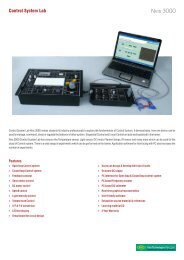
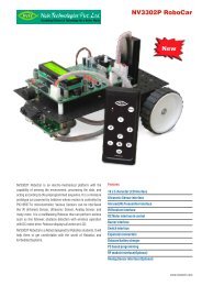
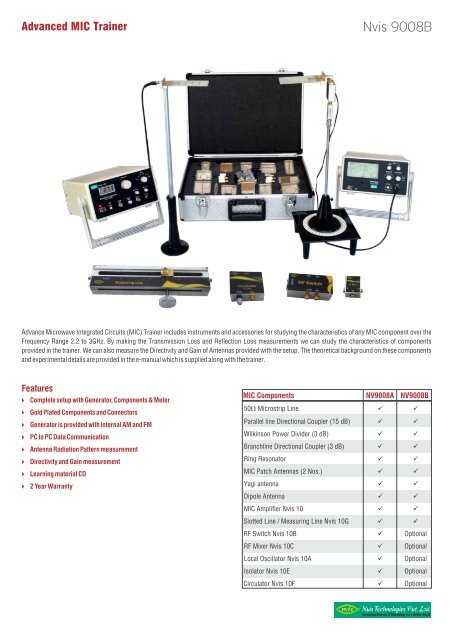
Advanced MIC Trainer<br />
<strong>Nvis</strong> 9008B<br />
Advance Microwave Integrated Circuits (MIC) Trainer includes instruments and accessories for studying the characteristics of any MIC component over the<br />
Frequency Range 2.2 to 3GHz. By making the Transmission Loss and Reflection Loss measurements we can study the characteristics of components<br />
provided in the trainer. We can also measure the Directivity and Gain of Antennas provided with the setup. The theoretical background on these components<br />
and experimental details are provided in the e-manual which is supplied along with the trainer.<br />
Features<br />
} Complete setup with Generator, Components & Meter<br />
} Gold Plated Components and Connectors<br />
} Generator is provided with internal AM and FM<br />
} PC to PC Data Communication<br />
} Antenna Radiation Pattern measurement<br />
} Directivity and Gain measurement<br />
} Learning material CD<br />
} 2 Year Warranty<br />
MIC Components NV9008A NV9008B<br />
50V Microstrip Line ü ü<br />
Parallel line Directional Coupler (15 dB) ü ü<br />
Wilkinson Power Divider (3 dB) ü ü<br />
Branchline Directional Coupler (3 dB) ü ü<br />
Ring Resonator ü ü<br />
MIC Patch Antennas (2 Nos.) ü ü<br />
Yagi antenna ü ü<br />
Dipole Antenna ü ü<br />
MIC Amplifier <strong>Nvis</strong> 10 ü ü<br />
Slotted Line / Measuring Line <strong>Nvis</strong> 10G ü ü<br />
RF Switch <strong>Nvis</strong> 10B ü Optional<br />
RF Mixer <strong>Nvis</strong> 10C ü Optional<br />
Local Oscillator <strong>Nvis</strong> 10A ü Optional<br />
Isolator <strong>Nvis</strong> 10E ü Optional<br />
Circulator <strong>Nvis</strong> 10F ü Optional<br />
Spreading Science & Technology for a Better World
Advanced MIC Trainer<br />
<strong>Nvis</strong> 9008B<br />
This Training System Includes<br />
1. <strong>Nvis</strong> 104 Microwave Generator (2.2 - 3GHz)<br />
2. <strong>Nvis</strong> 103 VSWR Meter<br />
3. MIC Components Kit with accessories<br />
4. Learning Material CD<br />
5. Transmitting & Receiving mast<br />
Scope of Learning<br />
—<br />
PC to PC Data Communication using MIC components<br />
—<br />
Measurement of Transmission Loss and Reflection Loss<br />
—<br />
Measurement of substrate dielectric constant using Ring Resonator<br />
—<br />
Measurement of power division, isolation and return loss<br />
characteristics<br />
—<br />
Measurement of coupling, isolation and return loss characteristics<br />
—<br />
Measurement of coupling and directivity<br />
—<br />
Measurement of power division and isolation characteristics<br />
NV104 Microwave Generator<br />
Frequency Range : 2.2 - 3GHz continuously variable<br />
Display : 16 x 2 LCD<br />
Display Accuracy : 40MHz<br />
Impedance : 50V<br />
Min RF level : 5mW<br />
Output Level Variation : 10 - 20 dB<br />
Operating Modes : Sweep, CW, Int. AM, Int. FM, Ext. AM,<br />
PC communication<br />
Modulating Frequency : 100Hz to 5kHz AM square wave,<br />
FM triangular wave<br />
—<br />
Measurement of characteristics of Patch Antennas<br />
—<br />
Measurement of characteristics of an MIC Amplifier<br />
—<br />
To study RF switch<br />
—<br />
To study RF Mixer<br />
—<br />
Measurement of Guide wavelength, Free Space Wavelength & SWR<br />
using Slotted line / Measuring Line<br />
—<br />
Measurement of Directivity & Gain of Antennas : Yagi Antenna, Patch<br />
Antenna, Dipole Antenna<br />
—<br />
To study the characteristics of Isolator<br />
—<br />
To study the characteristics of Circulator<br />
Power Supply : 230 V ±10%, 50 Hz<br />
Power Consumption<br />
: 5V A (approximate)<br />
Dimension (mm) : W 262 x D 316 x H 130<br />
NV103 VSWR Meter<br />
Sensitivity : 0.1 µV for 200 W input impedance<br />
for full scale deflection<br />
Noise Level : Less than 0.02 µV<br />
Range : 0 - 60 dB in 10 dB steps<br />
Input : Un-biased low and high impedance<br />
crystal biased crystal (200 & 200 K)<br />
Meter Scale : SWR 1-4, SWR 3-10, dB 0-10, expand<br />
SWR 1-1.3, dB 0-2<br />
Gain Control : Adjusts the reference level, variable<br />
range 0 -10 dB (approx)<br />
Input Connector : BNC (F)<br />
Input Frequency : 1000 Hz ±10%<br />
Power Supply : 230 V ±10%, 50 Hz / 60 Hz<br />
on request<br />
Power consumption : 2 VA (approx)<br />
Dimension (mm) : W 262 x D 316 x H 130<br />
Accessories<br />
—<br />
Matched Loads (5 Nos.)<br />
—<br />
Short<br />
—<br />
Coaxial Detector<br />
—<br />
Microstrip Directional Coupler (10 dB)<br />
—<br />
SMA to SMA Adapters (Both male & female)<br />
—<br />
SMA (male) connector fitted cables<br />
—<br />
Attenuator (3 dB)<br />
—<br />
+12V DC Adaptor<br />
—<br />
Transmitting & Receiving Mast<br />
—<br />
Radiation pattern graphs<br />
—<br />
SMA (Male) to BNC (Female) adaptor<br />
—<br />
3-pin Lunar cable<br />
Spreading Science & Technology for a Better World
Advanced MIC Trainer<br />
<strong>Nvis</strong> 9008B<br />
<strong>Specification</strong> of MIC Components<br />
1) Test Jig<br />
It includes of the following:<br />
a) 10 dB directional coupler<br />
b) Detector<br />
c) Shorts<br />
d) Matched Loads<br />
e) Attenuator<br />
2) Branch Line Coupler<br />
Dielectric material : Ceramic Substrate<br />
Dielectric constant : 3.02<br />
Coupling<br />
: 3dB<br />
3) Parallel Line Directional Coupler<br />
Dielectric Material : Ceramic Substrate<br />
Dielectric Constant : 3.02<br />
Coupling<br />
: 15dB<br />
4) Power Divider<br />
Dielectric Material : Ceramic Substrate<br />
Output Power : 3dB<br />
Return Loss : 8dB<br />
Dielectric Constant : 3.02<br />
5) Ring Resonator<br />
The Resonance freq. : 2.4GHz<br />
Dielectric material : Ceramic Substrate<br />
Dielectric constant : 3.02<br />
6) 50E Microstrip Line<br />
Dielectric material : Ceramic Substrate<br />
Dielectric constant : 3.02<br />
7) RF Switch (Pin Modulator)<br />
Frequency Range : DC to 5GHz<br />
Rise/fall time : 6ns typical<br />
Type<br />
: SPDT<br />
8) RF Mixer<br />
Frequency Range : 2.0 to 7.0GHz<br />
Conversion Loss : 6.2dB typical<br />
L-R Isolation : 30dB typical<br />
RF Power<br />
: 50mW<br />
9) Local Oscillator<br />
Frequency Range : 2 to 3GHz<br />
Tuning Voltage : 5V DC<br />
Operating Voltage : 5V DC<br />
10) Slotted Line / Measuring line<br />
Dielectric Material : Ceramic Substrate<br />
Dielectric Constant : 3.02<br />
11) Isolator<br />
Isolation<br />
: 15 dB<br />
Impedance : 50 Ohms<br />
Insertion loss : 0.8 dB Max<br />
Avg Power<br />
: 5W<br />
Design Tolerance : ±5%<br />
12) Circulator<br />
Isolation<br />
: 15 dB<br />
Impedance : 50 Ohms<br />
Insertion loss : 0.8 DB Max<br />
Avg Power<br />
: 5W<br />
Port : 3<br />
Design Tolerance : ±5%<br />
Designed & Manufactured by :<br />
<strong>Nvis</strong> Technologies Pvt. Ltd.<br />
141-A, Electronic Complex, Pardesipura, Indore - 452 010 India<br />
Tel.: 91-731-4211500, Telefax: 91-731-4202959, E-mail: info@nvistech.com, Website : www.nvistech.com<br />
Spreading Science & Technology for a Better World<br />
Subject to Change, V1-01012013<br />
0218NV9008B_191211