
Create successful ePaper yourself
Turn your PDF publications into a flip-book with our unique Google optimized e-Paper software.
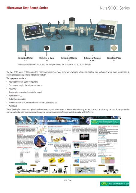
Microwave Test Bench <strong>Series</strong><br />
<strong>Nvis</strong> <strong>9000</strong> <strong>Series</strong><br />
Dielectric of Teflon<br />
2.1<br />
Dielectric of Nylon<br />
3.4<br />
Dielectric of Ebonite<br />
2.7<br />
All the samples (Teflon, Nylon, Ebonite, Perspex & Wax) are available in 10, 20, 30 mm length.<br />
Dielectric of Perspex<br />
0.03<br />
Dielectric of Wax<br />
2.2<br />
The <strong>Nvis</strong> <strong>9000</strong> series of Microwave Test Benches are precision made microwave systems, which use standard type rectangular wave-guide components to<br />
illustrate the essential elements of this field for study.<br />
The equipment consist of :<br />
—<br />
A selection of wave-guide components<br />
—<br />
The power supply for the microwave source<br />
—<br />
A detector<br />
—<br />
A meter, which monitors the detector output<br />
—<br />
A Demo Video CD<br />
—<br />
Audio Communication<br />
—<br />
Provided with PC to PC communication in Gunn based Benches<br />
—<br />
Wall Chart<br />
These Training Benches are completely self-contained & provide the means to allow students to carry out practical work at extremely low cost. A comprehensive<br />
manual containing extensive microwave theory and a progressive series of assignments is supplied with the Trainer.<br />
Wall Chart<br />
Spreading Science & Technology for a Better World
Microwave Test Bench <strong>Series</strong><br />
Microwave Test Bench <strong>Nvis</strong> <strong>9000</strong><br />
(Klystron Based)<br />
Experiments that can be performed<br />
—<br />
Study of the characteristics of klystron tube and to determine its<br />
electronic tuning range<br />
—<br />
To determine the frequency & wavelength in a rectangular waveguide<br />
working on TE mode<br />
10<br />
<strong>Nvis</strong> <strong>9000</strong> <strong>Series</strong><br />
—<br />
To determine the standing wave ratio and reflection coefficient<br />
—<br />
To measure an unknown impedance with Smith Chart<br />
—<br />
To study the square law behaviour of a microwave crystal detector<br />
—<br />
To study the voice communication by using microwave test bench<br />
—<br />
To study the variable attenuator<br />
Microwave Test Bench <strong>Nvis</strong> 9001<br />
(Gunn Based)<br />
Experiments that can be performed<br />
—<br />
To study the V-I characteristics of Gunn Diode<br />
—<br />
To study the voice communication by using microwave test bench<br />
—<br />
To study the following characteristics of Gunn Diode<br />
- Output power and frequency as a function of voltage<br />
- Square wave modulation through Pin Diode<br />
—<br />
To determine the frequency & wavelength in a rectangular waveguide<br />
working on TE10 mode<br />
—<br />
To determine the standing wave ratio and reflection coefficient<br />
—<br />
To measure an unknown impedance with Smith Chart<br />
—<br />
To study the square law behaviors of a microwave crystal detector<br />
—<br />
To study the PC to PC data communication<br />
—<br />
To study the variable attenuator<br />
Microwave Test Bench <strong>Nvis</strong> 9002<br />
(Klystron/Gunn Based)<br />
Experiments that can be performed<br />
—<br />
Study of the characteristics of Klystron tube and to determine its<br />
electronic tuning range<br />
—<br />
To determine the frequency in a rectangular waveguide working on TE10<br />
mode<br />
—<br />
To measure the polar pattern and the gain of following antennas<br />
- Standard Gain Horn - Pick up horn<br />
- Slotted Broad Wall - Slotted Narrow Wall<br />
- Dielectric Antenna - E-plane Sectorial Horn<br />
- H-Plane Sectorial Horn - Pyramidal Horn - Parabolic Dish<br />
—<br />
To study the square law behaviour of a microwave crystal detector.<br />
—<br />
To study the voice communication by using microwave test Bench.<br />
—<br />
To study the variable attenuator<br />
Spreading Science & Technology for a Better World
Microwave Test Bench <strong>Series</strong><br />
<strong>Nvis</strong> <strong>9000</strong> <strong>Series</strong><br />
Microwave Test Bench <strong>Nvis</strong> 9002A<br />
(Klystron Based/Gunn based)<br />
To study the variable attenuator<br />
All the experiments of <strong>Nvis</strong> 9002 can be performed in this model using<br />
PC interfaced Motorized unit.<br />
Radiation pattern of Pickup Horn Antenna<br />
Features<br />
} Microcontroller Based High Precision DC Stepper Motor<br />
} Automatic Zero Point setting<br />
} Built-in DC Power Supply<br />
} Instant Plotting of radiation Pattern<br />
} Resolution : 1°<br />
} RS232 data link to PC<br />
} Software running under Windows 98<br />
} PC Based Motorized Unit<br />
Radiation pattern of Horn Antenna<br />
Technical Specifications<br />
Microwave Input<br />
: From Gunn / Klystron source<br />
Detector<br />
: With BNC output<br />
Antenna Rotation<br />
: 360° (1° Resolution)<br />
Power Supply<br />
: 230V ±10%, 50Hz<br />
Power Consumption<br />
: 22V A (approximate)<br />
Accessories :<br />
Mains Cord<br />
BNC-BNC Cable<br />
RS-232 Cable<br />
Radiation Pattern Plotting Software<br />
Application software window<br />
Spreading Science & Technology for a Better World
Microwave Test Bench <strong>Series</strong><br />
Microwave Test Bench <strong>Nvis</strong> 9003<br />
(Gunn Based)<br />
Experiments that can be performed<br />
—<br />
To study the V-I characteristics of Gunn Diode<br />
—<br />
To study the following characteristics of Gunn Diode<br />
- Output power and frequency as a function of voltage<br />
- Square wave modulation through Pin Diode<br />
—<br />
To determine the frequency & wavelength in a rectangular waveguide<br />
working on TE 10 mode<br />
—<br />
To determine the standing wave ratio and reflection coefficient<br />
—<br />
To study the square law behaviour of a microwave crystal detector<br />
—<br />
To study the resonant cavity<br />
—<br />
Measurements of Dielectric constant.(Solid and liquid)<br />
- Low-loss solid dielectrics - Liquid dielectrics or solutions<br />
—<br />
To study the phase shift measurements by using phase shifter<br />
—<br />
To study the variable attenuator<br />
—<br />
To study the PC to PC data communication<br />
—<br />
To study the voice communication by using microwave test bench<br />
Microwave Test Bench <strong>Nvis</strong> 9004<br />
(Klystron/Gunn Based)<br />
Experiments that can be performed<br />
—<br />
Study of the characteristics of klystron tube and to determine its<br />
electronic tuning range<br />
—<br />
To determine the frequency & wavelength in a rectangular waveguide<br />
working on TE10 mode<br />
—<br />
To determine the standing wave ratio and reflection coefficient<br />
—<br />
To measure an unknown impedance with Smith Chart<br />
—<br />
To study the square law behaviour of a microwave crystal detector<br />
—<br />
Study of attenuators (fixed and variable type)<br />
—<br />
Study of Tee<br />
- E Plane Tee - H Plane Tee - Magic Tee<br />
—<br />
Study the function of multihole directional coupler by measuring the<br />
following parameters.<br />
- Main line & Auxiliary line VSWR<br />
- Coupling factor and directivity and Isolation<br />
—<br />
Study of circulators/Isolator<br />
—<br />
To study the voice communication by using microwave test bench<br />
—<br />
To study the PC to PC data communication (with Gunn based source)<br />
Microwave Test Bench <strong>Nvis</strong> 9005<br />
(Gunn Based)<br />
Experiments that can be performed<br />
—<br />
To determine the frequency & wavelength in a rectangular waveguide<br />
working on TE10 mode<br />
—<br />
To study the following characteristics of Gunn Diode<br />
- Output power and frequency as a function of Bias Voltage<br />
- Square wave modulation through PIN diode<br />
—<br />
To determine the Standing Wave-Ratio and Reflection Coefficient<br />
—<br />
To measure an unknown Impedance with Smith chart<br />
—<br />
To study V-I characteristics of Gunn Diode<br />
—<br />
To measure the gain of a waveguide horn antenna<br />
—<br />
Study the function of multi-hole directional coupler by measuring the<br />
following parameters :<br />
- To Measure main-line and auxiliary-line VSWR<br />
- To Measure the coupling factor and directivity and isolation.<br />
—<br />
Study of Magic Tee<br />
—<br />
To study the square law behaviour of a microwave crystal detector<br />
—<br />
The Q and bandwidth measurement in cavity resonantor<br />
—<br />
To Study the Attenuators (Fixed and Variable type)<br />
—<br />
To study the PC to PC data communication<br />
—<br />
To study the voice communication by using microwave test bench<br />
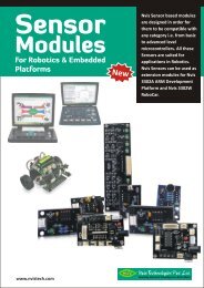
Microwave Fundamentals<br />
Microwave Fundamentals software is very powerful tool to understand<br />
core concept of Microwave Technology, throw high quality Simulation, rich<br />
theoretical content and attractive animated diagrams.<br />
It covers following topics.<br />
Electromagnetic Wave<br />
Basics of Electromagnetic waves<br />
Wave Guide<br />
Rectangular Wave Guide<br />
TE Modes, TM Modes, Field Patterns, Power Flow.<br />
Circular Wave Guide<br />
TE Modes, TM Modes, Field Patterns, Power Flow.<br />
Microwave Components<br />
Microwave Cavities, Microwave Hybrid Circuits<br />
Directional Coupler, Circulator and Isolator<br />
Microwave Tubes<br />
Velocity Modulation, Klystron, Magnetron, Traveling Wave Tube<br />
Microwave Active Components<br />
<strong>Nvis</strong> <strong>9000</strong> <strong>Series</strong><br />
Technology Learning Software Microwave<br />
Gunn Diode, IMPATT Diode, TRAPATT Diode, Tunnel Diode<br />
Spreading Science & Technology for a Better World
Microwave Test Bench <strong>Series</strong><br />
List of Benchwise Components<br />
<strong>Nvis</strong> <strong>9000</strong> <strong>Series</strong><br />
Note: NV is now <strong>Nvis</strong><br />
Microwave Component Technical Specification<br />
<strong>Nvis</strong> 201 Gunn Oscillator<br />
Gunn Oscillators are used to generate the microwave signal and its<br />
Micrometer is used to tune the output frequency of Gunn oscillator.<br />
<strong>Nvis</strong> 216 Waveguide Twist<br />
Waveguide Twist is used to change the plane of Polarization of a wave<br />
Guide transmission line . Twist is made from a section of waveguide which<br />
has been precisely twisted. 900 twist is a standard available model.<br />
Band C X<br />
Frequency(GHz) 3.95-5.85 8.2-12.4<br />
Waveguide WR187 WR-90<br />
Flange UG-149/U UG-39/U<br />
Pushing Factor 8 MHz/V --<br />
Bias Voltage max. 10V 10V<br />
Normal Power Output 5mW 10mW<br />
Temp. Coefficient ±0.2MHz/ C<br />
--<br />
Output Connection BNC(F) BNC(F)<br />
Frequency Adjustment By Micrometer By Micrometer<br />
Band<br />
X<br />
Frequency(GHz) 8.2-12.4<br />
Waveguide<br />
WR-90<br />
Flange<br />
UG-39/U<br />
VSWR<br />
1.09 At 10.5GHz<br />
Return Loss<br />
-26.9dB At 10.5GHz<br />
Spreading Science & Technology for a Better World
Microwave Test Bench <strong>Series</strong><br />
<strong>Nvis</strong> 212 Matched Termination<br />
Matched terminations are used to terminate the waveguide transmission<br />
line operating at low average power. The loads are carefully designed to<br />
absorb all the applied power and VSWR of matched termination is low.<br />
These are used in the measurement of reflection coefficient and where the<br />
matched load is required.<br />
<strong>Nvis</strong> 210 Movable Shorts /<br />
<strong>Nvis</strong> 235 Precision Movable Short<br />
<strong>Nvis</strong> <strong>9000</strong> <strong>Series</strong><br />
Movable shorts are used to obtain a phase reference in the calibration of<br />
various experimental setups .These are also used to vary the effective<br />
plane of reflection and therefore the phase of reflected wave. Movable<br />
shorts are used to measure the impedance of a device.<br />
Movable shorts are of two types one has no provision to record position of<br />
short in the waveguide and other type of movable short is precision<br />
movable short in which position of short can be accurately recorded from<br />
micrometer.<br />
Band C J X<br />
Frequency(GHz) 3.95-5.85 5.85-8.2 8.2-12.4<br />
Waveguide WR187 WR-137 WR-90<br />
Flange UG-149/U UG-344/U UG-39/U<br />
VSWR (1.02) (1.02) 1.03 At 10.5GHz<br />
Return Loss -- -- -33dB At 10.5GHz<br />
Av. Power 2W 2W 2W<br />
Type Fixed Fixed Fixed<br />
<strong>Nvis</strong> 238 Phase Shifter<br />
Many applications require phase shift to be introduced between two given<br />
position in a waveguide system. It consists of a dielectric slab or vane<br />
specially shaped to minimize reflection effect. Phase shifter are used to<br />
change the effective electrical length of transmission line without changing<br />
its physical length. They are particularly useful in microwave bridge circuit<br />
where the phase and amplitude must be adjusted independently.<br />
Band C J X<br />
Frequency(GHz) 3.95-5.85 5.85-8.2 8.2-12.4<br />
Waveguide WR-187 WR-137 WR-90<br />
Flange UG-149/U UG-344/U UG-39/U<br />
Reflection<br />
Coefficient (0.98) (0.98) 0.98<br />
<strong>Nvis</strong> 208 Tunable Probe<br />
Tunable probes are very useful devices to measure the SWR and<br />
Impedances. Tunable probe is consists of a crystal detector and a small<br />
wire antenna in coaxial housing. Its depth of penetration into the slotted<br />
section is variable.<br />
Band J X<br />
Frequency(GHz) 5.85-8.2 8.2-12.4<br />
Waveguide WR-137 WR-90<br />
Flange UG-344/U UG-39/U<br />
VSWR (1.3) 1.15 At 10.5GHz<br />
Return Loss -- -23.1 At 10.5GHz<br />
Calibration<br />
Accuracy (±2.5 ) ±2.5<br />
Band C J X<br />
Frequency(GHz) 3.95-5.85 5.85-8.2 8.2-12.4<br />
Detector IN21 IN23 IN23<br />
Output<br />
connector BNC(F) BNC(F) BNC(F)<br />
Type Tunable Tunable Tunable<br />
Spreading Science & Technology for a Better World
Microwave Test Bench <strong>Series</strong><br />
<strong>Nvis</strong> 220 Slide Screw Tuners<br />
Slide Screw Tuner is a very useful component in a microwave laboratory. It<br />
is mainly used for Impedance measurement. Its tuner can be adjusted for<br />
low and high impedance position.<br />
<strong>Nvis</strong> 203 Klystron Mount<br />
<strong>Nvis</strong> <strong>9000</strong> <strong>Series</strong><br />
Klystron mounts are used to transmit microwave power from reflex klystron<br />
tube to rectangular waveguide. Klystron mounts are designed by a section<br />
of waveguide, one end of waveguide is fitted with a movable short plunger.<br />
A small hole on the broad wall of waveguide is provided through which<br />
coupling pin of reflex klystron tube enters into the waveguide. By moving<br />
plunger (matching the impedance of klystron tube and waveguide)<br />
maximum output can be achieved.<br />
Band J X<br />
Frequency(GHz) 5.85-8.2 8.2-12.4<br />
Waveguide WR-137 WR-90<br />
Flange UG-344/U UG-39/U<br />
Max. VSWR -- 20 : 1.02<br />
Band C J X<br />
Frequency(GHz) 3.95-5.85 5.85-8.2 8.2-12.4<br />
Waveguide WR-187 WR-137 WR-90<br />
Flange UG-149/U UG-344/U UG-39/U<br />
<strong>Nvis</strong> 202 Pin Modulator<br />
Pin diode modulators are used to provide amplitude or pulse modulation in<br />
wide range of microwave to study many applications. These modulators<br />
uses PIN diode which is mounted across the waveguide line with RF<br />
isolated DC bias lead passing to an external TNC(F)<br />
<strong>Nvis</strong>205 Direct Reading Frequency Meter<br />
Direct Reading frequency meters are used to measure the microwave<br />
frequency accurately. There long scale length and numbered calibration<br />
marks provide high resolution which is particularly useful when measuring<br />
frequency difference of small frequency changes.<br />
Band C X<br />
Frequency(GHz) 3.95-5.85 8.2-12.4<br />
Waveguide WR-187 WR-90<br />
Flange UG-149/U UG-39/U<br />
Bias Voltage 0-12 Vpp 0-12 Vpp<br />
Output Connector TNC(F) TNC(F)<br />
Band C X<br />
Frequency Range(GHz) 3.95-5.85 8.2-12.4<br />
Waveguide WR-187 WR-90<br />
Flange UG-149/U UG-39/U<br />
Calibration Accuracy -- ± 2%<br />
Calibration Increment -- 5 MHz<br />
Max. VSWR -- 1.28 At 10.5GHz<br />
Return Loss -- -18.2 At 10.5GHz<br />
Spreading Science & Technology for a Better World
Microwave Test Bench <strong>Series</strong><br />
<strong>Nvis</strong> 225 Wave Guide Adaptor<br />
Adaptors transform waveguide impedance to coaxial impedance. Adopters<br />
consist of a short section of waveguide with a probe transition mounted on<br />
broad wall. Power can be transmitted in either direction. Each adaptor<br />
covers the 50% of the waveguide.<br />
<strong>Nvis</strong> 217-219 Fixed Attenuators<br />
<strong>Nvis</strong> <strong>9000</strong> <strong>Series</strong><br />
Attenuators are required to adjust power or attenuate the power flowing in<br />
waveguide.There are two type of attenuators fixed and variable. Fixed<br />
attenuators available in various range like 3dB,6dB,10dB etc. These<br />
attenuators are calibrated at center frequency of respective frequency band.<br />
By Variable attenuators power can be adjusted for different level.<br />
Band<br />
Frequency Range(GHz) 8.2-12.4<br />
Waveguide<br />
Flange<br />
Connector<br />
VSWR Max.<br />
Return Loss<br />
<strong>Nvis</strong> 206 Variable Attenuator<br />
10 dB / 20 dB<br />
X<br />
WR-90<br />
UG-39/U<br />
N Type (F)<br />
1.12 At 10.5GHz<br />
-24.5 At 10.5GHz<br />
Band C X<br />
Frequency Range(GHz) 3.95-5.85 8.2-12.4<br />
Waveguide WR-187 WR-90<br />
Flange UG-149/U UG-39/U<br />
VSWR Max. 1.08 1.06 At 10.5GHz<br />
Av. Power 2W 2W<br />
Accuracy ± 0.5 dB ± 0.5 dB<br />
Return Loss -- -31 dB At 10.5GHz<br />
<strong>Nvis</strong> 232 E-Plane Bends<br />
In measurements it is often necessary to bend a waveguide by some angle.<br />
Waveguide bends in E and H plane of 90° is normally available. Waveguide<br />
bends designed by a section of rectangular waveguide and flange.<br />
Band J X<br />
Frequency Range(GHz) 5.85-8.2 8.2-12.4<br />
Waveguide WR-137 WR-90<br />
Flange UG-344/U UG-39/U<br />
VSWR Max. 1.08 1.25 At 10.5GHz<br />
Av. Power 2 W 2 W<br />
Return Loss -- -19.23 At 10.5GHz<br />
Band C X<br />
Frequency Range(GHz) 3.95-5.85 8.2-12.4<br />
Waveguide WR-187 WR-90<br />
Flange UG-149/U UG-39/U<br />
VSWR Max. -- 1.25 At 10.5GHz<br />
Return Loss -- -25.7 dB At 10.5GHz<br />
Spreading Science & Technology for a Better World
Microwave Test Bench <strong>Series</strong><br />
<strong>Nvis</strong> 233 H Plane Bends<br />
<strong>Nvis</strong> 226, <strong>Nvis</strong> 253, <strong>Nvis</strong> 228<br />
Multihole Directional Coupler<br />
<strong>Nvis</strong> <strong>9000</strong> <strong>Series</strong><br />
Directional coupler are designed to measure incident and reflected power values and<br />
also provide a signal path to a receiver or perform other desirable operation. In its<br />
most common form, the directional coupler is a four fort waveguide junction<br />
consisting of a primary main waveguide and a secondary auxiliary waveguide. These<br />
are available in 3, 6,10, 20, 40 dB coupling.<br />
Band C X<br />
Frequency Range(GHz) 3.95-5.85 8.2-12.4<br />
Waveguide WR-187 WR-90<br />
Flange UG-149/U UG-39/U<br />
VSWR Max. -- 1.06 At 10.5GHz<br />
Return Loss -- -31 dB At 10.5GHz<br />
<strong>Nvis</strong> 229 Cross Directional Coupler<br />
For 10 dB<br />
Band<br />
X<br />
Frequency Range(GHz) 8.2-12.4<br />
Waveguide WR-90<br />
Flange<br />
UG-39/U<br />
VSWR Max.<br />
1.06 At 10.5GHz<br />
Return Loss<br />
-31 dB At 10.5GHz<br />
Coupling (dB) 10.1 ± 0.6<br />
Directivity (Min) 46.0 dB (3%)<br />
Cross Directional Coupler consists of two waveguide sectional joint at (90 ) with the<br />
coupling element mounted into the common broad wall.<br />
<strong>Nvis</strong> 236 Solid Dielectrical Cell<br />
These are used to measure dielectric constant of any solid material these<br />
consists of a cavity for keeping the sample and micrometer to read the<br />
position of sample.<br />
Band C X<br />
Frequency Range(GHz) 3.95-5.85 8.2-12.4<br />
Waveguide WR-187 WR-90<br />
Flange UG-149/U UG-39/U<br />
Coupling (dB) 20 dB 20 dB<br />
Directivity (Min) 25 dB 25 dB<br />
Coupling Accuracy ± 1 dB ± 1 dB<br />
Band<br />
X<br />
Frequency Range (GHz) 8.2-12.4<br />
Waveguide<br />
WR-90<br />
Flange<br />
UG-39/U<br />
Max. Length of cell<br />
100 mm<br />
Plunger Movement<br />
25 mm<br />
<strong>Nvis</strong> 237 Liquid Dielectrical Cell<br />
Band<br />
X<br />
Frequency Range(GHz) 8.2-12.4<br />
Waveguide<br />
WR-90<br />
Flange<br />
UG-39/U<br />
Max. Length of cell<br />
200 mm<br />
Plunger Movement<br />
65 mm<br />
Spreading Science & Technology for a Better World
Microwave Test Bench <strong>Series</strong><br />
<strong>Nvis</strong> <strong>9000</strong> <strong>Series</strong><br />
TEE<br />
Tees are used to combine power from two input or divided the microwave power from one input to two output lines. Tee is an intersection of three waveguides in the<br />
form of alphabet T.<br />
<strong>Nvis</strong> 221 E Plane Tee<br />
<strong>Nvis</strong> 222 H Plane Tee<br />
Band<br />
X<br />
Frequency Range(GHz) 8.2-12.4<br />
Waveguide<br />
WR-90<br />
Flange<br />
UG-39/U<br />
Max. Length of cell<br />
200 mm<br />
Plunger Movement<br />
65 mm<br />
Band C X<br />
Frequency Range(GHz) 3.95-5.85 8.2-12.4<br />
Waveguide WR-187 WR-90<br />
Flange UG-149/U UG-39/U<br />
<strong>Nvis</strong> 209 Wave Guide Detector Mount<br />
<strong>Nvis</strong> 223 Magic Tee /<br />
<strong>Nvis</strong> 248 E-H Tee<br />
The crystal detector can be used for the detection of microwave signal. At low level of<br />
microwave power, the response of each detector approximates to square law<br />
characteristics and may be used with a high gain selective amplifier having a square<br />
law meter calibration.<br />
Band<br />
X<br />
Frequency Range 8.2-12.4<br />
Waveguide<br />
WR-90<br />
Flange<br />
UG-39/U<br />
Band C J X<br />
Frequency Range(GHz) 3.95-5.85 5.85-8.2 8.2-12.4<br />
Waveguide WR-187 WR-137 WR-90<br />
Flange UG-149/U UG-344/U UG-39/U<br />
Detector IN21(any IN21 (any IN21(any<br />
equivalent) equivalent) equivalent)<br />
Output Connector BNC (F) BNC (F) BNC (F)<br />
Spreading Science & Technology for a Better World
Microwave Test Bench <strong>Series</strong><br />
<strong>Nvis</strong> 204 Ferrite Isolator,<br />
<strong>Nvis</strong> 230 T Circulator, <strong>Nvis</strong> 231 Y Circulator<br />
The ferrites isolators and circulators are matched 2 port and 3 port devices<br />
respectively, which offer low insertion loss and high isolation over 1GHz<br />
band width. An isolator is a 2 port device which allows signals from port<br />
1 to port 2 & provides maximum attenuation for transmission from port<br />
2 to 1. A circulator is a three port device which has a peculiar property of<br />
coupling power to the adjacent port clockwise<br />
<strong>Nvis</strong> 255 Micrometer Type Frequency Meter<br />
<strong>Nvis</strong> <strong>9000</strong> <strong>Series</strong><br />
Micrometer type frequency meters are consists of a microwave cavity with<br />
plunger and a section of waveguide. It consists of a micrometer to measure<br />
its position for measuring frequency.<br />
Band C J X<br />
Frequency Range 3.95-5.85 5.85-8.2 8.2-12.4<br />
Waveguide WR-187 WR-137 WR-90<br />
Flange UG-149/U UG-344/U UG-39/U<br />
Max. VSWR 1.2 -- 1.15<br />
Min. Insertion Loss 0.4dB -- 0.46 dB<br />
Min. Isolation 20dB -- 20 dB<br />
Return Loss -- -- 22.4<br />
<strong>Nvis</strong> 239-247 Waveguide Antennas<br />
There are several types of microwave antennas like standard Gain,<br />
Pyramidial horn, Pick up horn, Dielectric antenna, Parabolic dish antenna<br />
etc. these are used to radiate microwave energy in the air and to receive the<br />
energy from air.<br />
Band C X<br />
Frequency Range 3.95-5.85 8.2-12.4<br />
Waveguide WR-187 WR-90<br />
Flange UG-149/U UG-39/U<br />
Max. VSWR -- 1.15<br />
Calibration Accuracy -- ± 2 %<br />
Calibration Increment -- 10 MHz<br />
<strong>Nvis</strong> 207 Slotted Section<br />
Slotted section is used to measure various measuring parameter in<br />
microwave. for example to determine VSWR, phase and impedances.<br />
These consists of a slot in center of waveguide in which we can connect a<br />
probe and probe can be moved in slot and position of probe can be<br />
measured by its Varnier scale. The travel of probe carriage is more than<br />
three times of half wavelength.<br />
Frequency Flange Waveguide Antennas Gain<br />
Range(GHz) Designation Type Type<br />
8.2-12.4 GHz UG-39/U WR-90 Pyramidal 16<br />
8.2-2.4 GHz UG-39/U WR-90 Pick Up 10<br />
8.2-12.4 GHz UG-39/U WR-90 E-Section 15<br />
8.2-12.4 GHz UG-39/U WR-90 H-Section 15<br />
8.2-12.4GHz UG-39/U WR-90 Parabolic dish --<br />
8.2-12.4GHz UG-39/U WR-90 Standard Gain --<br />
8.2-12.4GHz UG-39/U WR-90 Dielectric Antenna --<br />
Designed & Manufactured by :<br />
<strong>Nvis</strong> Technologies Pvt. Ltd.<br />
141-A, Electronic Complex, Pardesipura, Indore - 452 010 India<br />
Tel.: 91-731-4211500, Telefax: 91-731-4202959, E-mail: info@nvistech.com, Website : www.nvistech.com<br />
Band C J X<br />
Frequency Range 3.95-5.85 5.85-8.2 8.2-12.4<br />
Waveguide WR-187 WR-137 WR-90<br />
Flange UG-149/U UG-344/U UG-39/U<br />
Residual VSWR -- -- 1.01<br />
Slope (dB) -- -- ± (0.2dB)<br />
Spreading Science & Technology for a Better World<br />
Subject to Change, V1-02012013<br />
0156NV<strong>9000</strong>_050811