View Complete Issue PDF - O&P Library
View Complete Issue PDF - O&P Library
View Complete Issue PDF - O&P Library

You also want an ePaper? Increase the reach of your titles
YUMPU automatically turns print PDFs into web optimized ePapers that Google loves.
June 1979<br />
Volume 33<br />
Number 2<br />
FOIWOEB [»1<br />
Orthotics<br />
and<br />
Prosthetics<br />
Journal of the American Orthotic and Prosthetic Association
Keep Sticky Back VELCRO Fasteners<br />
where they'll do the most good.<br />
VELCRO brand fastener tapes, with self-stick adhesive backing, in<br />
convenient dispenser packs.<br />
Versatile, hard-working VELCRO hook and loop fasteners, now available with-<br />
pressure sensitive adhesive backing that will stick almost anywhere. Ideal for<br />
attaching straps or padding to hard-surface materials—splints, braces, stands,<br />
frames. Simply peel off protective cover strip, press tape into place. Tape fasteners<br />
are ready to use immediately, open and close hundreds of times while adhesive<br />
backing holds like glue. Efficient, self-standing, shelf-size boxes keep your Sticky<br />
Back VELCRO fasteners on the job and hospital clean. Separate boxes for hook or<br />
loop tapes; convenient measuring device on each box.<br />
Contact your supplier today<br />
IMPORTANT TO REMEMBER: All hook and loop fasteners look much alike. But<br />
they don't function that way. For dependabilily'ssake; demand the best—VELCRO<br />
brand fasteners. You can't afford less.<br />
a<br />
a
American<br />
Orthotic & Prosthetic<br />
Association<br />
1979 National Assembly September 26 Thru 30,1979<br />
Washington Hilton, Washington, D.C.<br />
For Program Details and Registration Information<br />
write to<br />
The American Orthotic and Prosthetic Association<br />
1444 N Street, N.W.<br />
Washington, D.C. 20005<br />
The Assembly is open to all who are interested in the rehabilitation of the orthopedically disabled.
Orthotics<br />
and<br />
Prosthetics<br />
Editor<br />
A. Bennett Wilson, Jr.<br />
Managing Editor and Design<br />
Brian A. Mastro<br />
June 1979 Volume 33, No. 2<br />
CONTENTS<br />
Commentary: Our Present Challenge<br />
Kurt Marschall<br />
Suspension of the Below-Knee Prosthesis: An Overview<br />
Charles Pritham<br />
Vacuum-Forming Procedure for Fabrication of Non-Standard<br />
Spinal Orthoses<br />
Larry Mortensen<br />
The Genucentric Knee Orthosis—A New Concept<br />
Robert Foster, John Milani<br />
Evaluation of Ultralight BK Prosthesis<br />
Brian Reed, A. Bennett Wilson, Jr., Charles Pritham<br />
Individual Engineering—Orthopedic Care for Patients<br />
with Infantile Cerebral Palsy<br />
R. Volkert<br />
Technical Note<br />
Gary Supan<br />
20<br />
31<br />
45<br />
54<br />
63<br />
New Publications 67<br />
Classified Ads 68<br />
Editorial Board<br />
Alvin L. Muilenburg, C.P.O.<br />
1979<br />
Michael Quigley, C.P.O. Thomas Bart, CO.<br />
1979 1980<br />
Michael Pecorella, C.P.O. Kurt Marschall, CP.<br />
1979 1980<br />
GuntherGehl, CP.<br />
1981<br />
William L. McCulloch<br />
Ex Officio<br />
Copyright © 1979 by the American Orthotic and Prosthetic Association<br />
Printed in the United States of America.<br />
All Rights Reserved<br />
Second Class Postage Paid<br />
at Washington, D.C<br />
US ISSN 0030-5928
Advertiser's Index and Hotline<br />
Ace<br />
213-644-9336<br />
X<br />
Becker<br />
313-644-4540<br />
Drew Shoe<br />
614-653-4271<br />
Florida Brace<br />
305-644-2650<br />
GTR Plastics<br />
614-498-8304<br />
Hallmark<br />
213-446-4882<br />
VIII<br />
XVI<br />
XV<br />
II<br />
X<br />
Jobst C-3<br />
419-698-1611<br />
Johnson & Johnson<br />
201-524-0400<br />
Knit-Rite<br />
VI<br />
XVIII<br />
800-821-3094<br />
Otto Bock<br />
Pel<br />
XVII<br />
XII<br />
216-267-5775<br />
Red Cross<br />
XVI<br />
Smalley & Bates C-2<br />
201-661-5155<br />
Sutton<br />
XIX<br />
314-225-5255<br />
Truf orm<br />
IX<br />
513-271-4594<br />
Trumold<br />
716-874-3474<br />
Washington Prosthetics<br />
202-628-1037<br />
VIII<br />
XI<br />
Advertisers shown in bold-face type are member of<br />
The American Orthotic and Prosthetic Association<br />
Orthotics and Prosthetics is issued in March, June, September, and December.<br />
Subscription price, payable in advance, is $10.00 a year in the U.S. and Canada.<br />
Rate elsewhere is $11.00 a year. Single issues, $3.00 each. Publication does<br />
not constitute official endorsement of opinions presented in articles. The Journal<br />
is the official organ of the publisher, The American Orthotic and Prosthetic<br />
Association in collaboration with the American Academy of Orthotists<br />
and Prosthetists, and serves as the U.S. organ for Interbor. All correspondence<br />
should be addressed to: Editor: Orthotics and Prosthetics, 1444 N St., N.W.,<br />
Washington, DC. 20005. Telephone, Area Code 202, 234-8400.<br />
Orthotics and Prosthetics is indexed by Current Contents/Clinical Practice.<br />
IV
THE AMERICAN ORTHOTIC AND PROSTHETIC<br />
ASSOCIATION<br />
OFFICERS<br />
President—William M. Brady, CP.<br />
Kansas City, Missouri<br />
President-Elect—William D. Hamilton, CP.<br />
Scottsdale, Arizona<br />
Vice President—John E. Eschen, C.P.O.<br />
New York, New York<br />
Region I—John Ficociello, C.P.O.<br />
Burlington, Vermont<br />
Region II —Robert Mandfredi, C.P.O.<br />
Long Branch, New Jersey<br />
Region III—Ivan Sabel, C.P.O.<br />
Bethesda, Maryland<br />
Region IV—Frank Floyd, C.P.O.<br />
Wilmington, North Carolina<br />
Region V—Joseph Shamp, CP.<br />
Canfield, Ohio<br />
Region VI—Jack Milburn, CO.<br />
Springfield, Illinois<br />
REGIONAL<br />
Secretary-Treasurer—Thomas R. Bart, CO.<br />
Omaha, Nebraska<br />
Immediate-Past President-<br />
Daniel G. Rowe, C.P.O.<br />
St. Paul, Minnesota<br />
DIRECTORS<br />
Region VII—Thomas R. Bart, CO.<br />
Omaha, Nebraska<br />
Region VIM —Clint Snell, C.P.O.<br />
Shreveport, Louisiana<br />
Region IX—Joseph Lydon, CO.<br />
San Francisco, California<br />
Region X—Dale Jenkins, CP.<br />
Phoenix, Arizona<br />
Region XI-Joseph H. Zetti, CP.<br />
Seattle, Washington<br />
THE AMERICAN ACADEMY OF ORTHOTISTS AND<br />
PROSTHETISTS<br />
OFFICERS<br />
President—Michael Quigley, C.P.O.<br />
Downey, California<br />
President-Elect—<br />
Edward Van Hanswyk, CO.<br />
Syracuse, New York<br />
Vice President—Robert F. Hayes, CP.<br />
West Springfield, Massachusetts<br />
Secretary-Treasurer—Richard LaTorre, CO.<br />
Schenectady, New York<br />
Immediate-Past President-<br />
Siegfried W. Paul, C.P.O.<br />
Newington, Connecticut<br />
DIRECTORS<br />
Eugene Filippis, C.P.O.<br />
Detroit, Michigan<br />
J. Donald Coggins, CO.<br />
Philadelphia, Pennsylvania<br />
Gunter Gehl, CP.<br />
Chicago, Illinois<br />
H.R. Lehneis, C.P.O.<br />
New York, New York<br />
V
You're<br />
in the<br />
Business<br />
You're in the business. You know how much the orthotic and prosthetic field has grown in<br />
the last decade. You know that complex technology has replaced the methods and devices<br />
of yesteryear. You know that a facility can not function without a qualified orthotist or prosthetist.<br />
You can look ahead to more growth, more development, and a need for more qualified<br />
pracitioners whose education has prepared them for the future.<br />
Where will we find these practitioners? At universities and colleges. Students are willing<br />
and eager to enter the professions; unfortunately, a professional education is expensive.<br />
You can assure our profession of a steady supply of well-educated, certified orthotic<br />
and prosthetic practitioners by giving to the American Orthotic and Prosthetic Education<br />
Fund, Inc., which | 1<br />
seeks out and aids deserving<br />
students.<br />
Your tax-deductible contribution<br />
will support the education<br />
of these bright young<br />
people. Your profession<br />
needs your help today, to educate<br />
the pracitioners of tomorrow.<br />
Send a check now.<br />
Yes, I'd like to help our industry by helping a deserving student of orthotics<br />
and prosthetics. Enclosed please find my check tor$<br />
Name<br />
Firm.<br />
Address<br />
City. . State Zip.<br />
(make checks payable to AOPEF, and mail to 1444 N St, NW, Wash., D.C 20005)<br />
VII
&<br />
Follow The<br />
Leader<br />
Elastic<br />
Slip-On<br />
Scalloped<br />
Center Tie,<br />
Open Toe<br />
mi<br />
S H O E S . I N C O R P O R A T E D<br />
The leader in quality. The<br />
leader in comfort. The leader<br />
in style. Tru-Mold makes a full line<br />
of custom shoes all carefully custom<br />
molded from plaster casts of the patient's<br />
feet. Shoes that are both comfortable<br />
and look great. Call or write today for a free<br />
catalog of shoe styles and casting information.<br />
Tru-Mold . . . For the finest in custom<br />
shoes.<br />
1695 Elmwood Avenue, Buffalo, New York 14207 (716) 874-3474<br />
Sandal<br />
For The <strong>Complete</strong> Line<br />
Of Orthopedic Appliances<br />
And Brace Components<br />
|ECKER<br />
ORTHOPEDIC APPLIANCE COMPANY<br />
OUR 44 t h<br />
YEAR<br />
Send for <strong>Complete</strong> Catalog<br />
1776 South Woodward Avenue, Birmingham, Michigan 48011<br />
VIII
P R E F A B R I C A T E D<br />
M I L W A U K E E<br />
G I R D L E S<br />
• Designed with even 3/16 thickness consistency throughout.<br />
• Made in either medium or low density polyethelene.<br />
• Extra high form for high curve correction.<br />
• Available in seven standard sizes.<br />
• Available in complete assembly from measurements or<br />
negative cast.<br />
(Measurement & technique instructions available.)<br />
a c e o r t h o p e d i c c o m p a n y<br />
11913 So. Prairie Ave., Hawthorne, Calif. 90250 • Phone (213) 644-9336. 644-5597<br />
the name HALLMARK<br />
for Excellence<br />
in Orthopedics<br />
Jewett<br />
H-46<br />
Brace<br />
HALLMARK Orthopedic Specialties<br />
Have been Known and Respected for<br />
Excellence in the Orthopaedic Community<br />
for over 33 Years of Continuing Service.<br />
IMMEDIATE<br />
DELIVERY<br />
(213) 446-4882<br />
Write for our {<br />
latest Catalog<br />
showing over 150<br />
Orthopedic items |<br />
a i i m a r i<br />
O R T H O P E D I C S P E C I A L T I E S<br />
P O B O X 898 • A R C A D I A . C A L I F O R N I A 91006<br />
Trademark Registered. U.S. Patent Office<br />
X
2-S2000<br />
Taylor<br />
2-S2400 2-S2150 2-S2170<br />
Williams Flexion Knight Spinal(Chairback) Knight-Taylor<br />
2000 SERIES<br />
SPINAL BRACES<br />
HIGHEST QUALITY AT MODEST<br />
PRICES<br />
Immediate Delivery From Stock<br />
Pictured are just four of our many braces that can help<br />
your profit picture. Quantity discounts available. Easy<br />
to fit from five stock sizes. Write us for our complete<br />
catalog. Better yet, give us a call at (202) 628-1037.<br />
We'll be happy to help in any way we can.<br />
WASHINGTON 4 0<br />
w<br />
patterson st., n.e.<br />
_ ' WASHINGTON, D.C. 20002<br />
PROSTHETIC (202) 628-1037<br />
SUPPLIES<br />
XI
FREE! HANDY<br />
TUBE OF<br />
POCKET-SIZED<br />
AMP-AID<br />
% A preventative salve to be used in areas that may become irritated due to<br />
wearing a prosthesis, jogging, hiking, playing tennis, etc.<br />
* Use AMP-AID at the first sign of redness.<br />
* For an existing skin irritation or discomfort, AMP-AID gives added comfort<br />
and promotes healing, while you continue your activities.<br />
Try AMP-AID yourself<br />
Give your patients AMP-AID<br />
1<br />
j<br />
A<br />
m mm.<br />
mrt€# too*<br />
bliitmr* and o *<br />
d o i l y i n a<br />
kx)p»»<br />
not b a
Commentary<br />
Our Present Challenge<br />
The field of Prosthetics and Orthotics has<br />
moved in giant strides in the last three<br />
decades. New materials have been introduced,<br />
new techniques have been developed,<br />
resulting in new fitting methods and complete<br />
redesign of our Prosthetic-Orthotic armamentarium.<br />
However, it behooves us not to rest on our<br />
laurels and past accomplishments, but to<br />
pause to take a look into our humble beginnings,<br />
when the predecessor of AOPA,<br />
OALMA, was organized in the forties. It took<br />
men of great determination and foresight to<br />
mold countless small Prosthetic and Orthotic<br />
splinter organizations into one nationwide<br />
association called AOPA.<br />
To these founding fathers, AOPA must<br />
have seemed like a rough and uncut precious<br />
stone looks to the diamond cutter's eye. They<br />
recognized full well that the potential was<br />
there, but to bring out the beauty in the precious<br />
stone, to make it shimmer and sparkle,<br />
they knew it would take the skillful hands of<br />
master craftsmen to cut the numerous facets<br />
into its sides.<br />
The first facet, and one of the most beautiful,<br />
was the realization that at long last they<br />
had attained some form of professionalism.<br />
Although vague at first, what did they come<br />
to learn? They learned that to be a professional<br />
you have to behave like one, not only<br />
towards your peers but also towards the professionals<br />
of other disciplines with whom you<br />
come in daily contact. Foremost, however, is<br />
the professional treatment and management<br />
of your patients.<br />
The founding fathers also realized that in<br />
order to preserve your professionalism, your<br />
knowledge in your chosen field must be superior<br />
to those outside it, and you must speak a<br />
unified language, which we call nomenclature.<br />
Our Prosthetic and Orthotic Teaching<br />
Institutions were a result of this realization,<br />
and so another facet was added to this rough<br />
and uncut stone of which I speak.<br />
Then came the introduction of new materials,<br />
namely plastics which revolutionized the<br />
field of Prosthetics and Orthotics as a whole<br />
and our approach to fitting and alignment<br />
principles in particular. Some gifted research<br />
scientists and engineers entered our field,<br />
joined hands with us and solved some of our<br />
troublesome technical and biomechanical<br />
problems that we neither had the time nor<br />
knowledge to solve. This made for a happy<br />
marriage between two highly skilled disciplines.<br />
By this time our precious stone was already<br />
recognized all over the world for its dazzling<br />
beauty and sparkle. But today we should<br />
take a long, hard look at where our profession<br />
stands and where it is heading in the years to<br />
come. Never before have I seen a situation<br />
which cries so loudly for intelligent planning<br />
and determined handling of affairs of our<br />
profession by our members and representatives.<br />
Today we are standing at a cross-road of<br />
whether to continue a policy that spells nonrecognition<br />
of standards by the State and Federal<br />
Governments, or whether we are willing<br />
to end this status quo, in reality a no-mansland,<br />
by fighting and striving for licensure by<br />
these governments through the only qualified<br />
body that I know of, namely our own American<br />
Board for Certification. As it stands<br />
today, the hippy is more protected from<br />
ending up with a crew cut at the hands of an<br />
unqualified barber, than are the crippled and<br />
disabled from mal-treatment by unqualified<br />
infiltrators into our field.<br />
In striving for this goal of licensure, however,<br />
we are not attempting to prevent anyone<br />
from entering our field. But we should make<br />
it unmistakably clear that our rules and regulations,<br />
self imposed for many years, are the<br />
only ones of sufficiently high caliber to command<br />
adherence to. It would be fool-hardy to<br />
step back even one iota from these rules and<br />
regulations that we established and fought for<br />
so long, under the guise that we might violate<br />
democratic principles. On the contrary, it is<br />
exactly our constant willingness to impose<br />
XIII
these high standards of performance and ethical<br />
conduct for the benefit and betterment of<br />
our patients that makes us more democratic<br />
to man-kind as a whole.<br />
In the absence of this recognition by State<br />
and Federal Government, we can only fall<br />
back on the old method of persuasion, trying<br />
to emphasize to physician, surgeon, and clinic<br />
chief alike the need to utilize, for the protection<br />
of his patient, only qualified practitioners<br />
and facilities. This also imposes the adherence<br />
to ethical standards on the part of the<br />
practitioner as far as his product and service<br />
are concerned. But in either case, our house<br />
must be kept free of unethical conduct,<br />
shoddy workmanship and deliberate noncompliance<br />
with a doctor's prescription. And,<br />
I much prefer our own broom for the job in<br />
the absence of government licensure, for<br />
eventually we can expect standards imposed<br />
upon us that might not be to our liking.<br />
To keep pace with constantly changing<br />
times, materials, designs and other developments,<br />
it is imperative that we take very serious<br />
our continuing education programs as<br />
they are now offered all over the land by the<br />
American Academy of Orthotists and<br />
Prosthetists. These work shops and seminars<br />
are designed not only for the facility owner or<br />
manager, but also for any member of his establishment<br />
who hungers for knowledge and<br />
appreciates such exposure.<br />
Only by accepting this continuous flow of<br />
learning and untiring effort to serve the disabled<br />
can you demand that you be respected<br />
as a professional. And the world will gladly<br />
give you that respect. From this resulting<br />
superior knowledge and constant pursuit of<br />
excellence, you can demand that you be treated<br />
as a professional. And the world will gladly<br />
afford you that treatment. These qualifications<br />
will entitle you to expect to be paid as a<br />
professional. And the world will gladly give<br />
you your due.<br />
Inherent rights bring with them inherent<br />
obligations. In this high standard of performance,<br />
we must not overlook a necessary professional<br />
relationship with our fellow practitioner.<br />
It is my firm belief that today new<br />
ideas and new concepts in Prosthetics and<br />
Orthotics should be willingly shared with<br />
everyone who wants to learn and listen. I<br />
shudder when I recall the days when trade<br />
secrets were jealously guarded and I cringe<br />
with pain when I remember when a successful<br />
Orthotist and Prosthetist was measured, not<br />
by his ability to rehabilitate the handicapped,<br />
but by how many of their shoes he could<br />
deposit on his employers bench on a weekly<br />
basis.<br />
Today every self respecting Orthotist and<br />
Prosthetist should give freely of his time and<br />
knowledge to teach his art and science to<br />
others, as the Medical Profession has done in<br />
such an outstanding manner long before us.<br />
Ever since the initiation of the Hippocratic<br />
Oath, which states in part: ". . . to consider<br />
dear to me . . . him who taught me this art<br />
... to look upon his children as my own<br />
brothers, to teach men this art if they so desire<br />
without fee or written promise."<br />
Our obligation as a professional continues<br />
with the dedication, devotion and support we<br />
are willing to give our organization and ruling<br />
body to which we profess to belong. But<br />
belonging means to participate. Belonging<br />
means to be productive. Belonging means to<br />
be active. Belonging means to speak out and<br />
to be heard of. Ours is this marvelous publication<br />
"Orthotics and Prosthetics," an ideal<br />
vehicle to disseminate your knowledge and<br />
your "know-how" in an unselfish manner to<br />
your peers.<br />
You must realize by now that this Journal is<br />
distributed not only in the United States, but<br />
enjoys a worldwide circulation. Its contents<br />
will always be the show-window for our professional<br />
state of affairs. It needs your input<br />
and your contribution. It needs you, who<br />
has been sitting on the sidelines for too long.<br />
And finally, a professional's obligation extends<br />
to untiring dedication to our patients.<br />
He entrusts his rehabilitation into our hands.<br />
It is he who relies on us to perform at the<br />
highest level always. It is he who can expect of<br />
us that we keep pace with changing times,<br />
that we persevere despite difficulties in attaining<br />
results, and that we display an unlimited<br />
ability for the absorption of the new. And he<br />
has every right to do so. It is only we who can<br />
lead the way to new heights in our chosen<br />
field of endeavor if the betterment of our patient<br />
remains paramount in our mind. This is<br />
what I believe in . . .<br />
Kurt Marschall, CP.<br />
Member of the Editorial Committee<br />
XIV
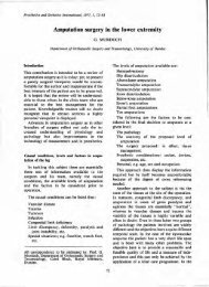
Suspension of the Below-Knee Prosthesis:<br />
An Overview<br />
CHARLES H. PRITHAM, C.P.0. 1<br />
The student of contemporary prosthetics<br />
cannot help but be struck by<br />
the plethora of techniques available for<br />
the suspension of the below-knee prosthesis.<br />
Since the introduction of the<br />
patellar-tendon bearing below-knee prosthesis<br />
in 1959 the field has been besieged<br />
by a variety of methods, all to accomplish<br />
a common purpose. The question that inevitably<br />
arises is "why?" Is it that the basic<br />
methods are so unsuccessful or that the<br />
possibilities for innovation so great?<br />
As an abundance of statistics will show,<br />
the predominant cause of amputation in<br />
western society is peripheral vascular<br />
disease, and increasingly the preferred<br />
site of amputation is below the knee. The<br />
below-knee prosthesis can, therefore, be<br />
characterized as the "bread and butter<br />
prosthesis," the one upon which the prosthetist<br />
counts to pay salaries and overhead.<br />
The tendency is to use the method<br />
which the prosthetist finds best enables<br />
him to satisfy the many needs of the patient<br />
most expeditiously and economically.<br />
The concern, of course, extends<br />
beyond the point of delivery and<br />
the prosthetist desires to find a technique<br />
that will be both durable and readily adjustable<br />
so as to facilitate repairs. There<br />
are, of course, other motives than base<br />
economics at work.<br />
Given this preponderance of experience<br />
with one basic prosthesis the practitioner<br />
in time develops the confidence for<br />
innovation. (The converse, of course, is<br />
true; one is more inclined to eschew experimentation<br />
when confronted with an<br />
unfamiliar situation.) Secure in the<br />
knowledge that he can always fall back<br />
on basic techniques the prosthetist is<br />
more likely to try out the newer methods<br />
he has learned of as well as his own ideas.<br />
This tendency is an outgrowth of not only<br />
a desire for innovation, but also in reply<br />
to perceived inadequacies of the older<br />
techniques that come with clinical experience.<br />
The majority of below-knee<br />
amputees seen not only provides motivation<br />
for new developments, but also<br />
scope. It is difficult to experiment with<br />
non existent patients as well as to gain the<br />
experience to either criticize established<br />
methods or to perceive the solutions.<br />
The answer to the question then would<br />
seem to be multifaceted. If financial<br />
forces were the only ones at work the<br />
ready and economical solution to obtaining<br />
proper suspension for a PTB with cuff<br />
suspension strap would simply be to add a<br />
waist belt, and we would not have witnessed<br />
the development of newer and<br />
more sophisticated methods. We may<br />
safely asume that prosthetists have been
motivated by such factors as a desire for<br />
personal satisfaction, to advance the profession,<br />
and a genuine wish to improve<br />
the lot of individual patients.<br />
In the following discussion two works<br />
in particular are regarded as benchworks:<br />
Orthopaedic Appliances Atlas<br />
Vol. 2 (1), and Human Limbs and their<br />
Substitutes (2). Published in 1960 and<br />
1956 respectively (after many years in<br />
preparation) they seem to mark the transition<br />
from a period of fertile investigation<br />
to a later period of intensive clinical<br />
application. Encapsulating the experiences<br />
of the first period on the one hand<br />
and presaging the events of the second on<br />
the other, the work of Dr. Eugene Murphy<br />
in both references must be cited as<br />
being of particular relevance to the question<br />
at hand.<br />
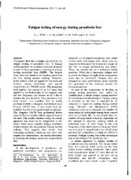
in Vol. 2 of the Orth. Ap. Atlas (3) quite<br />
clearly shows the use of a thigh corset and<br />
below-knee joints, and since then their<br />
use (until the introduction of the PTB)<br />
has become synonymous with the "conventional"<br />
below-knee prosthesis (Fig. 2).<br />
If properly contoured proximal to the adductor<br />
tubercle of the knee the thigh corset<br />
can provide suspension as well as<br />
Fig. 2. The "conventional" below-knee prosthesis<br />
Fig. 1. The Verduin Leg [From (3)]<br />
weight bearing and stabilization against<br />
anterior-posterior and medial-lateral<br />
forces. The thigh corset is not primarily<br />
prescribed for its suspension component,<br />
of course, and today thigh corsets and<br />
joints are added to the basic PTB in an<br />
attempt to bolster a stump that for one
eason or another is unable to cope with<br />
the external forces applied to it. None the<br />
less, in the spirit of extracting maximum<br />
performance from each component it<br />
would seem logical to properly contour<br />
a thigh corset when used to achieve<br />
suspension without a waist belt. The matter<br />
does not rest here, however.<br />
In Newsletter . . . Amputee Clinics<br />
Vol. VII, No. 3 June 1975 (4) the question<br />
of using a thigh corset with a PTB<br />
was raised with specific reference to<br />
whether or not the two were incompatible<br />
due to no allowance being made for relative<br />
motion between the prosthesis and<br />
patient's limb. In response to the question<br />
Hugh Panton described methods of dealing<br />
with the problem, including loosening<br />
the fit of the socket.<br />
In a subsequent issue of the newsletter<br />
(5) respondents to the questions, while<br />
not addressing themselves directly to the<br />
matter, tended to support Mr. Panton's<br />
rationale for modifying the socket. If this<br />
is the case then a thigh corset that fits intimately<br />
enough about the knee to provide<br />
adequate suspension can only exacerbate<br />
the problem. It may very well be<br />
then that a thigh corset incorporating<br />
suspension should not be fitted without a<br />
slip socket. There can be no ready solution<br />
to this conjecture and inevitably the<br />
decision must be made on an individual<br />
basis.<br />
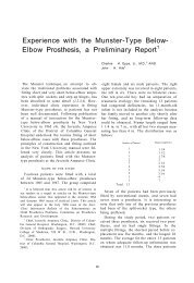
Fig. 3. The cuff suspension strap of the original<br />
PTB prosthesis<br />
Cuff Suspension Strap<br />
The cuff suspension strap (Fig. 3) is, of<br />
course, an integral part of the PTB prosthesis<br />
as described by Radcliffe and Foort<br />
(6) and as such has come to figure prominently<br />
in the present day practice of<br />
prosthetics. Prior to the introduction of<br />
the PTB Dr. Eugene Murphy has described<br />
the use of a soft suspension strap<br />
in conjunction with the "Muley" prosthesis<br />
(Fig. 4) (1, 2). As described by Dr.<br />
Murphy this precursor of the PTB had<br />
apparently been fitted for many years<br />
Fig. 4. The Muley Prosthesis [From (2)]
with mixed results with some patients<br />
resorting to the use of a thigh corset after<br />
only two or three years, while others continued<br />
to wear a Muley successfully for<br />
considerably longer periods. The disparate<br />
results were contributed by Dr.<br />
Murphy, not only to more accurate initial<br />
fitting, but also to more vigilant and frequent<br />
followup. (These same factors, of<br />
course, apply today and perhaps the true<br />
significance of the PTB is that they have<br />
become the norm rather than the exception.)<br />
In any event, the straps in the illustrations<br />
of Muley prostheses shown by Dr.<br />
Murphy are attached rather well forward<br />
of the position in vogue today.<br />
In their manual on the PTB, Radcliffe<br />
and Foort (6) give explicit directions for<br />
locating the attachment points as well as<br />
criteria for the proper function of the<br />
strap. These exacting conditions are<br />
somewhat difficult to fulfill and not all<br />
patients lend themselves to them; nor do<br />
all prosthetists rigorously make the attempt.<br />
The authors of the PTB manual<br />
implicitly recognized these facts when<br />
they gave equal space to fabrication of a<br />
waist belt as to a cuff suspension strap. It<br />
is interesting to speculate what percentage<br />
of PTBs fitted include a waist belt as<br />
well as a cuff suspension strap. Almost all<br />
temporary BK prostheses include a waist<br />
belt. It is the author's impression that<br />
even with definitive prostheses waist belts<br />
are used more often than circumstances<br />
dictate. That cuff suspension straps are<br />
soft and flexible items, and thus readily<br />
subject to stretching and wear, can only<br />
compound the problem. Recognition of<br />
these facts has given cause over the years<br />
to much innovation.<br />
The basic strap has been modified by<br />
the addition of elastic elements and<br />
replaced entirely by Velcro straps and<br />
single piece figure-of-eight straps. In<br />
their report on prosthetic devices suitable<br />
for India, Girling and Commings (7) describe<br />
such a strap that consists of a 25<br />
mm. wide cotton tape that wraps around<br />
the patient's knee, passes through two<br />
slots in the side of the prosthesis, passes<br />
posteriorly and is tied together anteriorly.<br />
A device is available commercially to<br />
facilitate location of the proper attachment<br />
points, and not least, such radically<br />
different means of suspension as the PTS<br />
socket have been advanced.<br />
Waist Belt<br />
A waist belt is most frequently added to<br />
the basic below-knee prosthesis in order<br />
to supplement the inadequate efforts of<br />
another suspensory component. As such<br />
it is most broadly referred to as a secondary<br />
or auxiliary means of suspension.<br />
This designation is questionable since it is<br />
possible to gain sufficient suspension with<br />
a waist belt without recourse to other<br />
means in just about every case, while a<br />
waist belt is added to a prosthesis after<br />
another form of suspension has proven its<br />
inadequacy. It would seem then that a<br />
case could be made for designating the<br />
waist belt a primary suspensor that<br />
relegates other suspensory components to<br />
a secondary role when used. Waist belts<br />
are objected to by prosthetists as<br />
unaesthetic and by patients as uncomfortable,<br />
difficult to keep clean, and frequently<br />
in need of repair. Perhaps then<br />
they should be reserved for last resort<br />
when other more appealing means have<br />
failed. All of this having been said, it<br />
must be acknowledged that there exists a<br />
place for the waist belt in the everyday<br />
practice of prosthetics.<br />
The first would, of course, be with a<br />
thigh corset and joints. In this instance<br />
the waist belt is most frequently attached<br />
to the prosthesis by means of a fork strap<br />
that divides proximal to the patella and<br />
courses down from there on either side of<br />
the patella to attach to the anterior portion<br />
of the prosthetic shin.<br />
Alternative means of attachment do<br />
exist although they are infrequently, if
ever, used. Dr. Murphy (2) describes<br />
what might be termed an abbreviated<br />
fork strap as it attaches on either side to<br />
the uprights proximal to the knee joint<br />
rather than distal to, as in the former<br />
case. He also mentions how rollers may<br />
be attached to the uprights and cords<br />
passed through them to correct with the<br />
waist belt posteriorly as well as anteriorly.<br />
This latter case would have the advantage<br />
of maintaining equal tension in all positions<br />
of hip flexion and of distributing<br />
the load more broadly about the belt.<br />
The second common use of a waist belt<br />
would be with a temporary PTB prosthesis<br />
and cuff suspension strap as mentioned<br />
earlier. The desire here, of course,<br />
is to provide a readily adjustable means<br />
of gaining good suspension during a<br />
period of rapid change and thus avoid the<br />
possibility of damage to the immature<br />
stump.<br />
The third use of a waist belt is with a<br />
definitive PTB for one reason or another.<br />
While other means of suspension exist,<br />
some prosthetists and clinic teams will<br />
resort to a waist belt rather than to other<br />
methods when the cuff fails as a means of<br />
suspension. The most compelling reason<br />
for this is mental confusion on the patient's<br />
part. Most people are familiar with<br />
fastening belts and straps and thus readily<br />
adapt to the use of a waist belt when<br />
they may have difficulty with other forms<br />
of suspension. When a waist belt is worn<br />
with a cuff suspension strap (particularly<br />
in this last cited case) it is not infrequent<br />
to see the cuff worn altogether too loose,<br />
either as a result of improper adjustment<br />
or of wear and stretching. In this case,<br />
then, the waist belt converts the cuff<br />
suspension strap to a form of fork strap<br />
that happens to be attached posterior to<br />
the knee center rather than anterior.<br />
One variant that gives recognition to<br />
this fact is that described by Jack<br />
Caldwell, C.P., in 1965 (8). The cuff<br />
suspension strap (Fig. 5 and 6) is done<br />
away with and replaced by two straps and<br />
a stainless steel ring as used in upper<br />
extremity prosthetic harnesses. As described,<br />
each strap is fastened at some<br />
point at the anterior portion of the<br />
socket, pass proximally up through the<br />
ring, and then distally to a point in the<br />
popliteal area of the socket. The straps<br />
are allowed to pass freely through the<br />
ring during flexion and extension and the<br />
ring is joined to the elastic thigh strap of<br />
the waist belt with a quick disconnect<br />
snap fastener. The author further states<br />
that hyperextension of the knee can be<br />
controlled by varying the location of the<br />
anterior attachment points.<br />
Suspenders<br />
Over the shoulder suspenders used with<br />
a below-knee prosthesis are so rare as to<br />
constitute a genuine curiosity when encountered.<br />
Their use can not be dismissed<br />
altogether, however. It may very<br />
well be that for any number of concomitant<br />
reasons a particular patient can use<br />
no other means of suspension; and there<br />
always exists the true individual who will<br />
hear of no other means however powerful<br />
the clinic team's arguments against it.<br />
The author encountered such a person a<br />
number of years ago who suspended his<br />
prosthesis (which also included a thigh<br />
corset) with an arrangement much the<br />
same as a baldric used to suspend a sword<br />
from the shoulder. A single broad belt<br />
passed proximally from the ASIS on the<br />
involved side up over the contralateral<br />
shoulder, distally down the back, and<br />
around the side to the originating point<br />
where the two ends were secured together.<br />
From there an elastic strap and "Y"<br />
strap were used to secure the baldric to<br />
the prosthesis.<br />
It is, of course, possible to devise considerably<br />
more complex arrangements<br />
using two suspenders, chest belt, waist<br />
belt, and either elastic straps anteriorposterior<br />
to the prosthesis or rollers and
Fig. 5. Top view of the V-straps with the knee<br />
extended<br />
Fig. 6. Posterior view of the V-straps while patient<br />
is standing<br />
roller cords. Franz and Aitken refer to<br />
such a setup for infants calling it a "toddler<br />
harness." The premise is that the<br />
chubby child and relatively indistinct<br />
skeletal features of the infant necessitate<br />
such drastic measures. An additional<br />
reason is, of course, the need to make the<br />
total prosthetic system "wriggle proof."<br />
Blevens Undercut Calf Socket<br />
The socket (Fig. 7) developed and<br />
patented by Emmett Blevens and evaluated<br />
by N.Y.U. can be regarded as a<br />
precursor of a number of concepts just<br />
recently beginning to receive serious attention.<br />
As described by Murphy (1) the<br />
socket was carved of wood to accommodate<br />
a stump encased in two wool stump<br />
sockets with a hollow carved in the<br />
posterior wall distal to the popliteal. A<br />
foam rubber pad was sandwiched between<br />
the two sockets so as to fill the<br />
hollow once the socket was properly<br />
donned. Since the pad was fitted so as to<br />
remain compressed, tension was developed<br />
between the socket and stump and a<br />
suspension effect was obtained. Apparently<br />
some amputees, with time and proper<br />
effort, were able to redevelop previously<br />
atrophied muscles and, thus,<br />
eventually discard the rubber pad. In addition,<br />
a sunction valve was fitted to some<br />
sockets and negative pressure was used to<br />
enhance suspension.<br />
This, the work of a private individual,<br />
failed to find favor with the "prosthetic<br />
establishment" and little or nothing has<br />
been heard of it since. The reasons for<br />
this conservatism are not hard to fathom.<br />
The PTB had not yet been properly introduced<br />
and once it was, considerable<br />
effort was necessary to overcome the<br />
obstinacy with which a corsetless BK<br />
prosthesis was greeted. In addition the
liner building up the posterior and<br />
medial areas proximal to the bulbous end<br />
of the stump. This liner is removed from<br />
the socket and donned separately and the<br />
stump and liner are then pushed into the<br />
socket. Mr. Hampton reports that considerable<br />
suspension can be gained by this<br />
expedient.<br />
Muscular Grasp<br />
Fig. 7. The socket designed by Blevens<br />
Blevens' socket, being carved of wood, required,<br />
as all such sockets, considerable<br />
skill and trial and error to fit and as such<br />
it was undoubtedly considered unprofitable<br />
to formalize the Blevens' method<br />
and teach it. While little information<br />
about the technique appears to be available<br />
and the efficacy of compressing the<br />
highly vascular structures of the posterior<br />
calf is open to question; the two hurdles<br />
mentioned have been conquered and perhaps<br />
the time is now ripe for further study<br />
of the methods of Blevens. As will be seen<br />
in the following discussion such study on<br />
the part of some researchers is underway.<br />
In a related development Fred Hampton<br />
of the University of Miami has in private<br />
communication described the use of a<br />
similar if not identical suspension technique<br />
(by serendipity and as auxiliary suspension<br />
only) for edematous and bulbous<br />
immature stumps frequently seen when<br />
fitting early temporary prostheses. In<br />
such instances to avoid damage to the<br />
fragile tissues, Mr. Hampton has used a<br />
Relatively little attention has been paid<br />
to this concept over the years. Dr. Murphy<br />
describes it in conjunction with the<br />
Blevens' socket (1) and Grevsten (9) mentions<br />
it in his description of the suction<br />
socket below-knee prosthesis. There can<br />
be little doubt that many amputees use it<br />
to supplement or eliminate more conventional<br />
means of suspension. More than<br />
one patient, when questioned closely, has<br />
described being able to walk short distances<br />
about the house without fastening<br />
the cuff; and this mechanism presumably<br />
accounts for the ability to ambulate<br />
without ill effects or complaints with an<br />
improperly fitting cuff suspension strap.<br />
The author encountered some years ago<br />
two young amputees (secondary to congenital<br />
defects) who had discarded any<br />
other forms of suspension. One, a young<br />
female in her teens, had literally thrown<br />
the medial brim of her supracondylar<br />
suspension prosthesis away, and the<br />
other, a female in her 30's, was an active<br />
skier who evinced a desire for an auxiliary<br />
suspension aid only in that activity.<br />
Recently Dr. Ernest Burgess of Seattle,<br />
Washington, has described his research<br />
in this area (10, 11) referring to it as<br />
physiological suspension. This is an<br />
outgrowth of his earlier work to create<br />
more functional stumps by such methods<br />
as myoplasty and myodesis, and has led<br />
him to re-evaluate the concepts of<br />
Blevens.<br />
Certainly, the idea is philosophically<br />
attractive. Not only would it result in a<br />
cleaner looking, more cosmetic prosthesis
without a cuff or supracondylar brims to<br />
protrude above the knee in sitting, promote<br />
greater activity of the remaining<br />
musculature with physiological benefits,<br />
it would also maximize the patient's<br />
potential to minimize his dependence on<br />
an external aid with important psychological<br />
and philosophical overtones. Certainly,<br />
the technique is not applicable to<br />
all patients and much work needs to be<br />
done to develop logical criteria for the<br />
method's application.<br />
Suction Socket<br />
In his discussion of suction socket<br />
below-knee prostheses Dr. Murphy (2)<br />
states that the U.S. Army's Commission<br />
on Amputations and prostheses in its tour<br />
of Germany after the war observed a few<br />
suction socket BKs and considered them<br />
relatively unsuccessful. Dr. Murphy attributed<br />
this to the relatively high ratio of<br />
bony prominences to soft tissues (as compared<br />
to the above-knee stump) and the<br />
consequent need to establish an initial accurate<br />
fit and subsequently maintain it<br />
with great accuracy despite changes in<br />
stump volume and contour. The attractions<br />
of suction are great and certainly<br />
are not to be dismissed lightly. If suspension<br />
can be established in the distal portion<br />
of the socket the proximal trim lines<br />
can be lowered with greater cosmesis and<br />
free the patient of constraints about the<br />
knee. Further, suction should reduce the<br />
possibilities of skin abrasions and increase<br />
the patient's awareness of the prosthesis.<br />
While American interest in the suction<br />
socket for the below-knee amputee has<br />
been dormant, since about 1968 Swedish<br />
investigators (9, 12) have been working<br />
with the PTB suction prosthesis. Considerable<br />
work has been done by them<br />
over the years to demonstrate the effects<br />
of suction sockets and this work was<br />
recently summarized by Grevsten in<br />
Prosthetics and Orthotics International<br />
(9). Similarly Gunnar Holmgren has<br />
discussed the matter from the prosthet<br />
stress the necessity to displace the soft<br />
tissues of the stump distally, both for<br />
safety in weightbearing and to develop<br />
tension between the skin and socket walls<br />
for suspension. Indeed Holmgren is quite<br />
emphatic about this being a major factor<br />
in the proper function of the PTB-suction<br />
socket. This use of tension between the<br />
socket walls and the skin is very similar if<br />
not identical to the principle used in the<br />
Blevens socket. However, as the information<br />
or technique is scanty it is difficult to<br />
fully assess these matters. One distrubing<br />
note concerning the Grevsten article (9)<br />
suggests itself. In the picture sequence<br />
showing the patient donning the prosthesis<br />
the use of a rubber suspension<br />
rubber suspension sleeve to preserve<br />
suction in extreme knee flexion is mentioned.<br />
The true advantage of a suction<br />
socket would seem to be the elimination<br />
of the necessity to encompass the knee<br />
for suspension.<br />
Rubber Sleeve Suspension<br />
Since about 1968 (13,14) the workers<br />
at the University of Michigan, Ann Arbor,<br />
have accumulated considerable<br />
experience with a form of suspension<br />
using a rubber sleeve (Fig. 8) in conjunction<br />
with and without a gel liner. In an<br />
article (13) describing an investigation of<br />
the functioning principles three suspensory<br />
forces are attributed to the rubber<br />
sleeve: negative pressure, friction between<br />
the stump and socket, and longitudinal<br />
tension in the sleeve. With the<br />
use of pressure transducers and by means<br />
of selectively introducing leaks in the<br />
sleeves of nine subjects the investigators<br />
were able to demonstrate to their satisfaction<br />
that negative pressure played an<br />
important role in the suspension of the<br />
protheses. It is interesting to note, as the<br />
investigators point out, that one subject<br />
with a very full and fleshy stump showed
advantage of suction suspension is the<br />
freeing of the knee joint from the constrictions<br />
necessary for suspension. A<br />
rubber suspension sleeve that passes<br />
proximal to the knee joint would seem<br />
to violate this principle. Whether or not<br />
it is possible to maintain suction without<br />
a sleeve remains to be established and the<br />
simplicity of application of the sleeve is<br />
certainly a point in its favor.<br />
Fig. 8. The rubber sleeve suspension technique<br />
no degradation of suspension affect when<br />
the sleeve was punctured.<br />
It is obvious, then, both from a clinical<br />
point of view and from laboratory<br />
studies that the rubber suspension sleeve<br />
is a relatively simple and effective means<br />
of suspension. The only question that<br />
remains is whether or not the suspension<br />
effect is worth more than the side effects.<br />
While doubtlessly many patients<br />
are more than satisfied using suspension<br />
sleeves other patients have been disturbed<br />
by the sense of constriction, heat and<br />
perspiration build-up under the sleeve,<br />
and the relative fragility of the sleeves.<br />
The question must, of course, be answered<br />
on an individual basis, but it is<br />
possible in a broader sense to register an<br />
objection on aesthetic or idealistic<br />
grounds. It would seem that the true<br />
Brim Suspension<br />
In contrast to the suspension techniques<br />
discussed until now, brim suspension<br />
techniques find no mention in the<br />
two works of Dr. Murphy cited earlier<br />
(1,2). It would seem then that the concept<br />
is a new one and a logical outgrowth<br />
of experience with the PTB (the author<br />
can not assert positively that there is no<br />
precursor as the world literature is unavailable<br />
and by no means has a search<br />
for historical predecessors been made).<br />
It is interesting that the extensive armamentarium<br />
of brim suspension techniques<br />
developed while such earlier forms<br />
of self-suspending sockets as suction and<br />
muscular grasp were slighted. It is also<br />
interesting that the pendulum has begun<br />
to swing in the other direction.<br />
In any event the central issue of brim<br />
suspension is how to permit passage of<br />
the wide femoral condyles through the<br />
relatively narrow inlet necessary to secure<br />
a proper grip immediately proximal to<br />
the adductor tubercle. It is the various<br />
solutions to this question that has given<br />
rise to the many variations reported on<br />
in the literature. In addition to suspension,<br />
extending the trimlines proximal<br />
affords other benefits as well. An increase<br />
in surface area encompassed leads to a<br />
decrease in the unit pressure, while the<br />
extension of lever arms proximally and<br />
intimate grip of the bony structure of the<br />
knee increases stabilization against such<br />
undesirable motions as lateral shift in<br />
the case of supracondylar suspension and
supracondylar-suprapatellar suspension pension techniques despite their many<br />
and, in addition, hyperextension in the points of similarity. It may be argued<br />
case of supracondylar-suprapatellar that it is unnecessary to develop such<br />
suspension. The net effect then of such a universal procedures but it should be kept<br />
prosthesis when properly fitted is an in mind that the present system,<br />
increase in patient control and comfort<br />
with a decrease in pistoning and other<br />
shrouded as it is in parochialism, denies<br />
all patients equal access to all the options<br />
undesirable motions. These positive and means that a prosthetist attempting<br />
benefits must be balanced by such negative<br />
an unfamiliar technique for the first<br />
factors as a possible decreased cosmesis, time may have nothing increased the weight, way of written<br />
greater expe<br />
difficulty in fitting, and difficulty in<br />
guidance to go on. This may very well<br />
adjustment to the supracondylar pressure.<br />
mean needless experimentation, frustration,<br />
It must also be remembered that<br />
brim suspension techniques have made and eventual abandonment of an<br />
otherwise successful variant.<br />
it possible to fit patients that otherwise<br />
would be unamenable to anything but<br />
knee joints and a thigh corset (15,16,<br />
17). For the most part, it is now necessary<br />
to resort to this latter extreme only<br />
in cases where the patient's stump needs<br />
positive relief from superimposed weight.<br />
The proliferation of PTB variants<br />
led the Veterans Administration to issue<br />
a Program Guide in 1970 (18) that organized<br />
the variants in a logical fashion,<br />
developed a consistent nomenclature,<br />
and gave recommendation for their<br />
prescription. Since then the nomenclature<br />
presented has come to be adopted<br />
by most writers in the field. Every attempt<br />
is made in the ensuing discussion<br />
to adhere to this standard nomenclature<br />
in referring to brim configurations.<br />
A revised version of the chart to reflect<br />
developments made since 1970 is shown<br />
in Figure 9. In a similar vein James<br />
Breakey (19) set forth the method he used<br />
to objectively determine the specific<br />
brim configuration (supracondylar vs.<br />
Supracondylar-suprapatellar) that best<br />
met a particular patient's needs. Despite<br />
these efforts, there is no universally<br />
agreed upon procedure or set of recommendations<br />
for prescribing brim configuration,<br />
wedge or suspension type, or<br />
socket type (hard vs. soft). Nor is there<br />
one manual or standard procedure for<br />
casting and fitting the various brim sus<br />
Supracondylar-Suprapatellar PTB<br />
(PTS)<br />
Apparently the first formal introduction<br />
of the supracondylar-suprapatellar<br />
technique (Fig. 10) occurred in a 1964<br />
edition of Atlas d'Appareillage Prosthe'tiq<br />
Pierquin, Fajal, and Paquin who referred<br />
to it as the PTS (Prosthe'se tibiale Supracondylienn<br />
the PTS and the PTB were covered in<br />
a subsequent issue of Orthotics and Prosthetics<br />
in 1965 (21). Kurt Marschall and<br />
Robert Nitschke described the PTS in<br />
the American literature first in 1966<br />
(22) and again in 1967 (23) and have<br />
become in time inextricably linked to<br />
the development of it in this country.<br />
As described by these various authorities<br />
the supracondylar-suprapatellar<br />
(SC-SP) PTB includes a flexible insert<br />
and extends proximal to the patella and<br />
femoral condyles. Great emphasis is put<br />
on the role of the suprapatellar identa<br />
for prevention of undesirable hyperextension<br />
of the knee by the patient in gait<br />
and stance. In contrast to the work of<br />
other developers relatively little emphasis<br />
is given in these early reports to the suspension<br />
possibilities inherent in the<br />
supracondylar extensions. More emphasis
that also provided support in the weightbearing<br />
areas. Hard socket PTB's with<br />
SC-SP suspension continue in use but<br />
their use is very much taken for granted<br />
as there is little or nothing published<br />
describing the particular features or<br />
problems involved in their use. Presumably<br />
the lack of a yielding or removable<br />
element above the condyles<br />
would imply that a hard socket PTB<br />
with SC-SP suspension would be used for<br />
a patient for whom only a small reduction<br />
in supracondylar ML was necessary<br />
or who could achieve sufficient suspension<br />
elsewhere (suprapatellar, muscular<br />
grasp, etc.). Patients who wear such a<br />
socket generally don it from the posterior<br />
aspect through the suprapopliteal opening<br />
with a corkscrewing motion.<br />
Removable Medial Wedge<br />
Fig. 10. The PTS system<br />
is given to their contribution to stabilization<br />
of the prosthesis.<br />
While the names of Nitschke and Marschall<br />
have become almost synonymous<br />
with the use of a liner, in both articles<br />
(22,23) they describe in passing the use<br />
of a hard socket and even mention in one<br />
(23) the possibility of using compressible<br />
medial and lateral wedges in a hard socket,<br />
if necessary. Similarly, Breakey and<br />
Foort in 1970 (24) described a SC-SP<br />
PTB featuring a socket laminated of<br />
flexible polyester connected to a pylon<br />
by a rigidly laminated socket receptacle<br />
In 1966 Dr. C.G. Kuhn (25) published<br />
details of a prosthesis he named Kondy<br />
1966 Carlton Fillauer (26) published in<br />
Orthotics and Prosthetics details of the<br />
development and fabrication of a similar<br />
design (Fig. 11) based on Dr. Kuhn's<br />
work. Mr. Fillauer proposed to call this<br />
prosthesis the S.T.P. or Supracondylar<br />
Tibia Prosthesis. Neither name ever<br />
really caught on and today the design is<br />
generally referred to as PTB with removable<br />
medial wedge or PTB with Fillauer<br />
wedge.<br />
In any event, whatever the name, it<br />
describes a hard socket PTB cut low over<br />
the patella with supracondylar wings and<br />
a removable medial wedge. The wedges<br />
are prefabricated of Plastisol, in a range<br />
of sizes and thicknesses and available<br />
from Fillauer Orthopedic Supply. In use<br />
the cast is taken over the wedge which is<br />
secured in place proximal to the medial<br />
condyle by a strip of tape. Elastic plasterof-Paris<br />
bandage is used and snugly<br />
wrapped proximally to reduce the supracondylar<br />
ML diameter. Similarly the cast
Fig. 9. Variations of the Patellar-Tendon-Bearing (PTB) prosthesis (Revised from (18) to reflect
is filled with the wedge in place and the<br />
model is modified to provide a narrow<br />
lip in the socket proximal to the wedge<br />
to hold it in place. The socket is also<br />
laminated with the wedge in place.<br />
An interesting variation on the basic<br />
concept of a removable medial wedge is<br />
that developed at the Prosthetic Research<br />
Study in Seattle, Washington. Described<br />
as early as 1969 (27) this technique was<br />
described in greater detail by Joseph<br />
Zettl at the "Workshop on Below-Knee<br />
suspension variant peculiar to southern<br />
Florida where it has achieved a considerable<br />
measure of popularity. Perhaps<br />
the earliest mention of it in the literature<br />
occurs in the August 1970 issue of Newsletter<br />
. . . Amputee Clinics (29) in which<br />
Dr. Newton C. McCullough III briefly<br />
describes it and attributes its development<br />
to William Sinclair, then chief<br />
research prosthetist at the University of<br />
Miami. Similarly Dr. Augusto Sarmiento<br />
writing in the Spring 1971 issue of Bulletin<br />
of Prosthetic Research (30) describes<br />
the wedge and states that some<br />
200 patients had been fitted with it by<br />
that time.<br />
Essentially the medial and lateral<br />
brims of the PTB socket are extended<br />
proximally above the level of the adductor<br />
tubercle and during the fitting process<br />
a soft wedge similar in shape and crosssection<br />
to the removable medial wedges<br />
Fig. 11. The Fillauer removable medial wedge<br />
system<br />
sold by Fillauer Orthopedic Supply is<br />
located in place above the adductor<br />
tubercle so as to achieve proper suspension.<br />
and Above-Knee Prostheses" held in<br />
When proper shape and location of<br />
Seattle, Washington January 1973 (28). the wedge is determined it is glued in<br />
Basically, a custom fitted wedge is place and covered with leather. In use<br />
fabricated over the modified model of<br />
the patient's limb using nylon stockinette,<br />
then, to don or doff the prosthesis the<br />
patient would merely push or pull his<br />
Dacron felt, polyester resin, and Sulkafloc. limb One in or or two out pins of protrude the prosthesis medially and the<br />
from the wedge and lock it into place on<br />
the medial wall of the socket. If only one<br />
pin is used, the wedge is free to pivot<br />
during flexion of the knee, affording<br />
greater comfort to the amputee. This latter<br />
point is a refinement from the original<br />
technique where two pins were<br />
routinely used. Mr. Zettl emphasized that<br />
the wedge could be used with both supracondylar<br />
and supracondylar-suprapatellar<br />
sockets, any kind of soft insert,<br />
readily modified, and, if necessary, padded.<br />
Compressible Medial Wedge<br />
The Compressible Medial Wedge is a<br />
wedge would compress to allow passage<br />
of the femoral condyles. William Sinclair<br />
has stated (28) that in most instances<br />
a medial wedge alone has proven sufficient,<br />
but, if necessary, a lateral wedge
can be used and in cases of supracondylar-suprapatellar<br />
suspension the com<br />
positioned medially so that the entire<br />
with a curved metal bar and channel<br />
pressible wedge has been extended medial wall proximal to the widest point<br />
anteriorly proximal to the patella. These of the femoral condyles could be removed<br />
wedges are most often carved of the polyurethane and replaced. foam No attempt used for is SACH made foot to heel<br />
cushions using a wire wheel, although cushion or upholster the medial wedge<br />
Hugh Panton in personal communication<br />
has mentioned molding them of the opposition to those who advocated such<br />
and Mr. Fillauer stated his belief, in<br />
RTV Silicone Elastomer formerly used soft wedges, that hard wedges when<br />
for below-knee distal end pads.<br />
properly fitted were well tolerated by<br />
This then would seem to be a very useful<br />
and easily adopted suspension technique,<br />
and the reasons why it has not<br />
enjoyed wider popularity are somewhat<br />
puzzling. There would seem to be<br />
nothing radically different to be done in<br />
the casting and modification procedures<br />
and the carving and fitting of the wedge<br />
would seem to offer no particular difficulties.<br />
Once glued in place and covered<br />
the wedge is an integral part of the prosthesis<br />
and can not be removed and lost,<br />
which should be a welcome thought to<br />
those used to the vagaries of some patients'<br />
behavior.<br />
patients.<br />
The hardware has changed some since<br />
its original introduction but the method<br />
remains substantially unchanged. Material<br />
can be added or removed from the<br />
medial brim as necessary and indeed the<br />
fit can be altered if needed by bending<br />
the metal bar to bring the wedge in or out<br />
Removable Medial Brim<br />
Apparently the first mention of the<br />
removable brim (Fig. 12) technique<br />
occurs in June of 1971 in an edition of<br />
Newsletter . . . Amputee Clinics (31).<br />
Carlton Fillauer then gave fuller details<br />
of the rationale behind the brim's development<br />
and the fabrication technique<br />
in December 1971 (32). In this article<br />
Mr. Fillauer stated that the development<br />
of the removable medial brim resulted<br />
not from dissatisfaction with the removable<br />
medial wedge, but rather from<br />
the need for a technique to accommodate<br />
patients in whom the difference between<br />
the condylar ML diameter and the supracondylar<br />
ML diameter was greater than<br />
could be accommodated with the available<br />
prefabricated removable medial<br />
wedges. The method consists of fabricating<br />
a supracondylar PTB hard socket<br />
Fig. 12. The Fillauer removable brim system
or to change the angle relative to the<br />
sagittal plane. Further, the height of the<br />
wedge can be changed in a similar fashion.<br />
When properly finished the brim of<br />
the prosthesis presents a very acceptable<br />
cosmetic effect both sitting standing.<br />
While intended to be used with hard<br />
socket supracondylar PTB's it can be<br />
used with liners or in supracondylarsuprapatellar<br />
sockets. In this latter configuration<br />
the medial horizontal cut is<br />
extended anteriorly and meets with a<br />
vertical cut that splits the patella. The<br />
only problem that may be encountered<br />
with this variation is gapping of the<br />
vertical cut when the patient's knee goes<br />
into hyperextension in late stance phase.<br />
This gapping can be minimized by being<br />
certain that the bar and channel assembly<br />
are properly positioned on the midline<br />
of the medial wall or even slightly<br />
anterior to it.<br />
Inflatable Medial Wedge<br />
In March of 1973 (33) and again in<br />
December of 1973 (28) Timothy Staats<br />
described the development of inflatable<br />
medial wedge (Fig. 13) which he ascribed<br />
to Lincoln Baird. Basically two<br />
fluid filled bulbs are used with a short<br />
length of tube connecting the two and a<br />
needle valve used to control the passage<br />
of fluid between them. One, an ordinary<br />
rubber squeeze bulb as used in measuring<br />
blood pressure, is secured in the popliteal<br />
area of the prosthesis. The other resembles<br />
the removable medial wedge as<br />
described by Carlton Fillauer and is<br />
placed inside the prosthesis proximal to<br />
the medial femoral condyle. In use<br />
fluid would be pumped into the suspension<br />
wedge to affect suspension and<br />
evacuated to permit donning and doffing.<br />
The critical feature is that it permits<br />
the patient to adjust the suspension so<br />
suit himself and to accommodate fluctuations.<br />
Mr. Staats mentioned that a limited<br />
number of patients were fitted with very<br />
encouraging results, but that numbers<br />
were limited by the number of units<br />
available. Leakage apparently was a<br />
problem with the first units fabricated<br />
but this was subsequently eliminated.<br />
Since these early publications little or no<br />
information is available in print nor do<br />
the units seem to be commercially available.<br />
A telephone conservation with Mr.<br />
Staats in January of 1979 elicited the following<br />
facts. The inflatable wedge<br />
continued to be used for some 2 or 3<br />
years after 1973 and some 50 patients<br />
were fitted with it. Contrary to the early<br />
expectations leakage continued to be a<br />
problem and eventually the Removable<br />
Medial wall supplanted it. The inflatable<br />
wedge is no longer available and the<br />
remaining stock of some 50 units was<br />
donated to the prosthetic curriculum and<br />
UCLA where its use is still taught as one<br />
of the options to be considered for suspension<br />
of the PTB.<br />
Fig. 13. The inflatable medial wedge<br />
Conclusion<br />
A general overview of Below-Knee<br />
Prosthetic suspension techniques has
een conducted. In general, three broad<br />
trends can be discerned. First, a group of<br />
older suspension techniques have remained<br />
static and been supplanted by<br />
new ones since the introduction of the<br />
PTB and variants. Second, another<br />
group of techniques abandoned when the<br />
PTB was introduced have recently gained<br />
fresh appreciation. Third, an entire new<br />
group of suspension variants, all employing<br />
common principles, have emerged<br />
and gained widespread acceptance. It<br />
may very well be that the ultimate suspension<br />
technique is skeletal attachment<br />
but in the meantime there is no lack of<br />
options to be considered. What apparently<br />
is lacking is a universally accepted set<br />
of clearly enunciated guidelines to illuminate<br />
the situation.<br />
1Rehabilitation Engineering Center, Moss Rehabilitation<br />
Hospital-Temple University-Drexel<br />
Hospital, Philadelphia, Pa. 19141.<br />
BIBLIOGRAPHY<br />
1. Eugene F. Murphy, Ph.D. "Lower-<br />
Extremity Components," Orthopedic<br />
Appliances Atlas Vol. 2.<br />
J.W. Edwards, 1960, pp. 217-224.<br />
2. Eugene F. Murphy, Ph.D. "The<br />
Fitting of Below-Knee Prostheses,"<br />
Human Limbs and their Substitutes,<br />
Hafner Publishing Co.<br />
first edition 1956, second edition<br />
1968, pp. 719-724.<br />
3. American Academy of Orthopaedic<br />
Surgeons, "Historical Development<br />
of Artificial Limbs," Orthopedic<br />
Appliances Atlas Vol. 2.<br />
J.W. Edwards, 1960, p. 7.<br />
4. Hugh J. Panton, B.S., C.P.O.<br />
"Considerations for Joints and<br />
Corset," Newsletter . . . Amputee<br />
Clinics 8:3: June 1975, pp. 1-3,<br />
6-7.<br />
5. Committee on Prosthetics Research<br />
and Development, National Academy<br />
of Sciences, "Joints, Corsets,<br />
and PTB Sockets: Survey Report,"<br />
Newsletter . . . Amputee Clinics<br />
8:5: October 1975, pp. 5-7, 10-<br />
12.<br />
6. Radcliffe, C.W. and James W. Foort.<br />
The patellar-tendon- bearing<br />
below-knee prosthesis, Biomechanics<br />
Laboratory, University of<br />
California, 1961, pp. 119-130.<br />
7. John Girling and Gordon Cummings.<br />
"Artificial Limbs Fabrication<br />
without the Use of Commercially<br />
Made Components," Prosthetics<br />
International, 4:2, 1972, pp. 21-<br />
25.<br />
8. Jack Caldwell, C.P. "Inverted V-<br />
strap Suspension for PTB Prosthesis,"<br />
Artificial Limbs, 9:1:23-<br />
26, Spring 1965.<br />
9. S. Grevsten. "Ideas on the Suspension<br />
of the Below-Knee Prosthesis,"<br />
Prosthetics and Orthotics International,<br />
2:1: April 1978, pp. 3-7.<br />
10. Ernest M. Burgess, M.D. and A.<br />
James Moore. "A Study of Interface<br />
Pressures in the Below-Knee<br />
Prosthesis (Physiologic Suspension:<br />
An Interim Report)," Bulletin<br />
of Prosthetics Research, BPR<br />
10-28 Fall 1977, pp. 58-70.<br />
11. Ernest M. Burgess, M.D., Anne G.<br />
Alexander, R.P.T., and Charles<br />
P. Rubenstein, M.S. "The Effect<br />
of Stump-Muscle Activity on Socket<br />
Suspension and Prosthetic<br />
Control," Inter-Clinic Information<br />
Bulletin, 13:15: 11-17, December<br />
1974.<br />
12. Gunnar Holmgren. The PTB Suction<br />
Prosthesis from the written<br />
material of a lecture delivered at<br />
the third of the "Strathclyde<br />
Bioengineering Seminars 8-11<br />
August, 1978.
13. Naoichi Chino, M.D. et al. "Negative<br />
Pressures during Swing Phase<br />
in Below-Knee Prostheses with<br />
Rubber Sleeve Suspension,"<br />
Archives of Physical Medicine and<br />
Rehabilitation, Vol. 56, Jan.<br />
1975, pp. 22-26.<br />
14. Joseph P. Giacinto. "The Rubber<br />
Sleeve Suspension for Below-<br />
Knee Prostheses," Orthotics and<br />
Prosthetics 30:4:17-19, Dec.<br />
1976.<br />
15. Sam E. Hammontree, C.P., Howard<br />
J. Tyo, C.P. and Snowden Smith,<br />
C.P. "Twenty Months Experience<br />
with the PTS," Orthotics and<br />
Prosthetics 22:1:33-39, March<br />
1968.<br />
16. Gustav Rubin, M.D., Robert Nitschke,<br />
C.P., and Henry F. Gardner,<br />
C.P.O. "The Supracondylar-<br />
Suprapatellar PTB Prosthesis,"<br />
Bulletin of Prosthetics Research<br />
BPR 10-14, Fall 1970, pp. 102-<br />
106.<br />
17. James F. Richards, Jr., M.D., John<br />
N. Pierce, C.O. "Knee Disarticulation<br />
Successfully Fitted with a<br />
PTS Socket," Inter-Clinic Information<br />
Bulletin Vol. XVI Nos.<br />
3-4, March-April 1977, pp. 7-<br />
10, 17.<br />
18. Program Guide G-6 M-2, Part IX,<br />
April 1, 1970, "Variants of the<br />
PTB (Patellar Tendon Bearing)<br />
Below-Knee Prosthesis," Veterans<br />
Administration, Dept. of Surgery<br />
and Medicine, Prosthetic and Sensory<br />
Aids Service, Washington,<br />
D.C.<br />
19. James W. Breakey, B.Sc. "Criteria<br />
for Use of Supracondylar and<br />
Supracondylar-Suprapatellar Suspension<br />
in Below-Knee Prostheses,"<br />
Orthotics and Prosthetics<br />
27:3:14-18, September 1973.<br />
20. Pierquin, L., Fajal, G., and Paquin,<br />
d'Appareillage Prosthetique et<br />
Orthopedique, No. 1, 1964.<br />
21. Pierquin, L., Fajal, G., and Paquin,<br />
J.M. "Discussion Sur Les Prostheses<br />
Tibiales," Atlas d'Appareillage<br />
Prosthetique et Orthopedique,<br />
No. 9, 1965.<br />
22. Kurt Marschall, C.P. and Robert<br />
Nitschke, C.P. "The PTS Prosthesis,"<br />
Orthopedic and Prosthetic<br />
Appliance fournal, 22:2:123-<br />
126, June 1966.<br />
23. Kurt Marschall, C.P. and Robert<br />
Nitschke, C.P. "Principles of the<br />
Patellar Tendon Supracondylar<br />
Prosthesis," Orthopedic and Prosthetic<br />
Appliance fournal 21:1:33-<br />
38, March 1969.<br />
24. James Breakey, B.P.T. with an introduction<br />
by James Foort, M.A.<br />
Sc. "Flexible Below-Knee Socket<br />
with Supracondylar Suspension,"<br />
Orthotics and Prosthetics, 24:3:1-<br />
10, Sept. 1970.<br />
25. Kuhn, G.G., Burger, S., Schetter,<br />
R. and Fajal, G. "Kondylen Bettu<br />
Stumpf," "KBM Prosthese,"<br />
Atlas d'Appareillage Prosthetique<br />
et Orthopedique No. 14, 1966.<br />
26. Carlton Fillauer, C.P.O. "Supracondylar<br />
Wedge Suspension of the<br />
P.T.B. Prosthesis," Orthotics and<br />
Prosthetics, 22:2:39-44, June<br />
1968.<br />
27. Joseph H. Zettl, C.P. "Prosthetics<br />
Research Study, Progress Report,<br />
December 1, 1967—June 30,<br />
1969," Bulletin of Prosthetic Research<br />
BPR 10-12, Fall 1969, p.<br />
281.<br />
28. Hector W. Kay and June D. Newman.<br />
"Report of Workshop on<br />
Below-Knee and Above-Knee<br />
Prosthetics," Orthotics and Prosthetics,<br />
27:4:9-25, Dec. 1973.<br />
29. Newton C. McCollough, III, M.D.<br />
J.M.<br />
"Method for Suspension of Below-<br />
"Prosthe'se Tibiale a' Emboitage Supracpndylien," Atlas<br />
Knee Prostheses" Newsletter . . .
Amputee Clinics 2:4:8, August<br />
1970.<br />
Augusto Sarmiento, M.D. "Progress<br />
Report from the University of<br />
Miami, Miami, Fla." Bulletin of<br />
Prosthetics Research BPR 10-15,<br />
Spring 1971, p. 237.<br />
Carlton Fillauer, C.P.O. "Variations<br />
in Suspension of the PTB<br />
Prosthesis," Newsletter . . .<br />
Amputee Clinics 3:3:8, June<br />
1971.<br />
32. Carlton Fillauer, C.P.O. "A Patellar-Tendon-Bearing Socket with<br />
Detachable Medial Brim," Orthotics<br />
and Prosthetics 25:4:26-<br />
34, December 1971.<br />
33. Timothy Staats, M.A., C.P. "Inflatable<br />
Wedge Suspension System,"<br />
Orthotics and Prosthetics 27:<br />
1:34-37, March 1973.
Vacuum-Forming Procedure for the Fabrication<br />
of Non-Standard Spinal Orthoses<br />
Larry Mortensen, C.O. 1<br />
Today in orthotics there are many<br />
plastic orthotic modules readily available<br />
to the orthotist in the management of<br />
scoliosis and other spinal problems. The<br />
modular systems can be used most effectively<br />
in correcting and/or positioning,<br />
achieving good results in many cases.<br />
What about the patient who is hard to<br />
fit with a modular orthosis or the orthotist<br />
who would like a more intimate fit<br />
by controlling the modifications of the<br />
positive model?<br />
The "Drape Vacuum-forming Procedure"<br />
is a simple procedure for the fabrication<br />
of a "custom" orthosis that can be<br />
carried out easily by two people.<br />
Fabrication<br />
The first step in preparing the positive<br />
model for the vacuum-forming procedure<br />
is to draw a mid-line with indelible<br />
pencil down the posterior aspect of the<br />
model (Fig. 1).<br />
A long shaft 1/2-in. diameter drill is<br />
used to drill a hole from the distal to<br />
proximal surfaces parallel to the midline<br />
and from 1- 1/2 inches to 2 inches below<br />
posterior aspect of the model (Figs. 2-<br />
4). If the drill shaft is shorter than the<br />
length of the cast a hole can be drilled<br />
from the proximal end to meet the one<br />
started from the distal end, or vice versa.<br />
Fig. 1. The mid-line is used as a reference point<br />
for aligning bit when drilling longitudinal shaft.
Fig. 4. If the shaft of the drill is not long enough<br />
to reach the proximal end a hole to meet it is<br />
drilled.<br />
Fig. 2. Longitudinal shaft must be well below posterior<br />
surface to accommodate for irregularities in<br />
the posterior surface of the model, and to prevent<br />
cave-in from the drilling of the surface holes.<br />
A #29 drill is used to provide holes<br />
approximately 1/2 in. apart down the<br />
mid-line drawn on the posterior aspect of<br />
the model to connect with the longitudinal<br />
shaft (Figs. 5 and 6) to permit<br />
evacuation of air between the model and<br />
the plastic when the plastic is draped over<br />
the model.<br />
An air hose should be used to clear<br />
plaster debris from all surface holes and<br />
the main shaft. Once all holes are drilled<br />
and cleared, the interface is applied. The<br />
interface I prefer is medium density<br />
Pelite, non-perforated, 5 mm (3/16 inches),<br />
because of its resistance to compression<br />
during the vacuum-forming<br />
procedure.<br />
Fig. 5. Surface holes are drilled approximately<br />
inch apart to direct the flow of vacuum air evenly<br />
from around model when the plastic is draped and<br />
suction is applied.<br />
Fig. 3. The drill bit must be held level to posterior<br />
surface. It must not deviate from mid-line when<br />
drilling shaft. H.S. — horizontal shaft.
Fig. 6. Surface holes are used for evacuation of air<br />
from around the model, and for alignment of the<br />
posterior seam when draping plastic on model.<br />
The Pelite is heated at 265 deg F about<br />
one minute or until moldable. It is then<br />
stretched and wrapped with Ace bandage<br />
to conform to the model (Figs. 7 and 8).<br />
When the Pelite is cool, one side of the<br />
interface is stapled as close as possible<br />
along the surface holes (Fig. 9). Excess<br />
material is cut off, and the procedure is<br />
repeated on the opposite side (Fig. 10).<br />
The polyethelene may be formed<br />
directly over the Pelite liner in which case<br />
the two materials are bonded to each<br />
other. However, I prefer to place a layer<br />
of cotton stockinet (Fig. 11) over the<br />
liner-covered model to prevent bonding<br />
because this arrangement permits the<br />
insertion of pads between the liner and<br />
shell if needed and finishing is easier<br />
when the two materials are separate.<br />
Proximal and distal end caps fabricated<br />
of Plastizote and about one inch large<br />
in diameter than the proximal and distal<br />
ends are put into place and the proximal<br />
Plastizote cap is heated in the center<br />
with a heat gun and pulled over the end<br />
of the pipe to form a nipple (Fig. 12).<br />
A small "X" is cut into the top of the<br />
Fig. 7. The Pelite interface is heated, then stretched over the model.
Fig. 8. Ace bandage is used to hold Pelite in place.<br />
nipple and pulled down, exposing the<br />
pipe.<br />
The proximal cap is sprayed with a<br />
foam type of upholsterer's contact cement<br />
and attached to the model. The nipple<br />
opening is taped securely with electrical<br />
tape at the base of the pipe forming an<br />
air-tight connection. The distal cap is<br />
then placed on the model and an "X"<br />
marked on the Plastizote indicating the<br />
location of the horizontal shaft hole (Fig.<br />
13). The "X" area is again heated to form<br />
a nipple and cut as before. The vacuum<br />
supply hose is placed into the distal end<br />
cap nipple and taped securely. It should<br />
extend about 1/2 inch beyond the inside<br />
of the nipple so that it may be inserted<br />
Fig. 9. When the Pelite is cool one edge is stapled<br />
as close as possible along the surface holes.<br />
Fig. 10. Excess Pelite is cut off and the edge is stapled<br />
along the surface holes.
Fig. 11. Cotton stockinet is used to provide a nonadhering<br />
interface between Pelite and plastic<br />
sheet.<br />
Fig. 12. The polyethylene foam Plastizote end cap<br />
is heated and a nipple is formed to be used to secure<br />
end cap to pipe.<br />
Fig. 13. Locating distal horizontal shaft to form<br />
nipple.<br />
Fig. 14. The vacuum supply hose is inserted in the<br />
distal end cap nipple and taped securely.
Fig. 15. P.P.A. (posterior proximal arrow) points to surface holes and is used for alignment of plastic<br />
when molding.<br />
Fig. 16. P.D.A. (posterior distal arrow) points to surface holes and is used for alignment of plastic<br />
when drape molding.
into the horizontal air shaft when the<br />
cap is cemented to the model as before<br />
(Fig. 14). After the Plastizote end caps<br />
are cemented in place they are trimmed<br />
about the periphery to about 1/4 in.<br />
from the stockinet to insure a good contact<br />
surface between plastic and the end<br />
caps so the vacuum can draw the air<br />
around the model.<br />
The openings of the longitudinal hole<br />
are located and marked on the proximal<br />
(Fig. 15) and distal (Fig. 16) end caps<br />
with an arrow. The anterior surface of<br />
the model is bisected and the location is<br />
marked on the Plastizote end caps,<br />
proximal and distal (Fig. 17). The cotton<br />
stockinet is then sprayed with a Silicone<br />
parting agent or is powdered so that<br />
plastic will not adhere to the Pelite or<br />
stockinet.<br />
(Fig. 18). The "alignment marks" insure<br />
the proper alighment of the plastic to<br />
the proximal and distal marks on the<br />
model during the draping phase of the<br />
vacuum-forming procedure.<br />
It is best that the oven be preheated to<br />
265-270 deg F (125 to 130 C.) before<br />
insertion of the plastic. The moldability<br />
of the plastic varies according to the<br />
type of oven used and the heating time<br />
involved. For example, it will take approximately<br />
35 to 40 minutes at 265-<br />
270 deg F for moldable condition to be<br />
reached in a non-circulating gas oven<br />
while a Grieye's electric circulating oven<br />
IT IS VERY IMPORTANT that the<br />
end caps are kept clean to insure proper<br />
adherence of the plastic. The end caps<br />
are cleaned with acetone and the model<br />
is now ready for the vacuum-forming<br />
phase.<br />
The thermoplastic I like to use is 5<br />
mm. (3/16 inch), low density polyethelene. I prefer the low density polyethylene<br />
for its combination of physical<br />
strength characteristics. Polyethylene<br />
has exceptional resistance to chemicals<br />
and a fair drawing ratio (2.5:1). An<br />
orthosis fabricated from low density<br />
polyethylene is easier for a patient to don<br />
and will not fatigue and crack from<br />
flexure of the orthosis when it is donned.<br />
To determine the size of the material<br />
for draping, two measurements are needed.<br />
The largest diameter of the model,<br />
plus 7.5 cm. (3 in.) is the circumferential<br />
width. The length of the model plus<br />
3.75 cm. (1-1/2 in.) will give you the<br />
total length of the material.<br />
The plastic is placed on a bench and<br />
the circumferential width of the model is<br />
divided in half; markers are placed<br />
proximally and distally on the plastic<br />
Fig. 17. Proximal anterior alignment mark and<br />
distal anterior alignment mark on end caps.
will require 15 to 20 minutes for the<br />
same amount of material. This time is<br />
based on a piece of plastic 35 in. x 22 in.<br />
x3/16in.<br />
The plastic is heated at a low temperature<br />
to prevent surface pooling and<br />
shringkage caused by higher temperatures.<br />
Lower temperatures actually expand<br />
the material from 1.5 cm. (1/2<br />
inch) to 2.5 cm. (1 inch), in length and<br />
width. Obviously, at the lower temperature<br />
the material retains its solidity and is<br />
easier to handle when being removed<br />
from the oven for draping.<br />
The plastic is now placed in the oven;<br />
15 to 20 minutes for a circulating oven,<br />
or 35 to 40 minutes for a non-circulating<br />
oven. When the plastic reaches the stage<br />
of moldability it becomes transparent<br />
throughout. The vacuum pump is turned<br />
on and set at 20 to 28 inches of mercury<br />
vacuum. The heating tray is taken from<br />
the oven and the heated plastic removed<br />
by two people grasping the corners of<br />
either end. The plastic is lifted from the<br />
tray and held over the model. It is then<br />
lowered to the model, the alignment<br />
marks on the plastic coinciding with the<br />
proximal and distal alignment marks<br />
on the model (Fig. 19). The ends of the<br />
plastic are released and permitted to<br />
hang; the corners are taken proximally<br />
and brought together at the proximal<br />
posterior (alignment arrow). The plastic<br />
is pressed to the end cap, making sure the<br />
polyethylene adheres to the Plastizote<br />
Fig. 18. A.M. (alignment mark). These alignment marks will coincide with proximal and distal alignment<br />
marks on end caps when plastic is draped onto model./ This also will allow equal amount of material to fall<br />
to each side; thus reducing the amount of stretch needed to bring ends of plastic to midline and maintaining<br />
a uniform thickness throughout.
Fig. 19. Heated plastic is aligned over model. Fig. 21. The heated plastic is molded over the<br />
distal end cap.<br />
Fig. 20. The heated plastic is molded over the proximal end cap.
Fig. 22. The heated plastic is pressed together along the surface holes and the air is withdrawn.<br />
Fig. 23. Lateral view of orthosis just after removal<br />
from model.<br />
Fig. 24. Posterior view of orthosis just after<br />
removal from model.
(Fig. 20). This is repeated on the distal<br />
posterior area (Fig. 21). When the ends<br />
of the plastic are properly aligned and<br />
the plastic is pressed circumferentially<br />
to the end caps, the plastic along the surface<br />
holes is pressed together and the<br />
vacuum process begins evacuating the<br />
air from around the model, forming the<br />
plastic to the model (Fig. 22).<br />
The vacuum pump remains on until<br />
the plastic is cool and once again opaque.<br />
The plastic is then trimmed from the<br />
model when it has been completely<br />
cooled as shown in Figures 23, 24, and<br />
25.<br />
Summary<br />
This paper presents a simple method of<br />
drape vacuum forming of T.L.S.O.<br />
and L.S.O. Using this procedure an orthosis<br />
can be fabricated for the difficult,<br />
non-standard patient.<br />
Here at the Rehabilitation Engineering<br />
Center of Children's Hospital at<br />
Stanford, we have fabricated over 100<br />
T.L.S.O. and L.S.O.'s, using this procedure.<br />
The longitudinal shaft and surface<br />
holes that are used for suction and alignment<br />
can be placed anteriorly, lateral<br />
or posterior, depending on where opening<br />
is needed in the orthosis. Finally,<br />
this is not the answer to all vacuumforming<br />
procedures, but just one that<br />
may help manage the unusual needs of<br />
some of our patients.<br />
Fig. 25. Anterior view of orthosis just after<br />
removal from model.<br />
References<br />
Footnotes<br />
1Head of Orthotics, Rehabilitation<br />
Engineering Center, Children's Hospital<br />
at Stanford, 520 Willow Road, Palo<br />
Alto, California 94304.<br />
1. Artamonov, Alex. Orthotic-Prosthetic Developments,<br />
Ortho-Pros, Fall 1971.<br />
2. Artamonov, Alex. Vacuumforming of Sheet<br />
Plastics, Ortho-Pros, Spring 1973.<br />
3. Artamonov, Alex. Vacuumforming Techniques<br />
and Materials in Prosthetics and Orthotics,<br />
Inter-Clinic Information Bulletin,<br />
July 1972.<br />
4. Wilson, A. Bennett. Vacuumforming of<br />
Plastics in Prosthetics and Orthotics, Orthotics<br />
and Prosthetics, March 1974.
The Genucentric Knee Orthosis—A New Concept<br />
ROBERT FOSTER, B.S. 1<br />
JOHN MILANI, B.S., CPO 2<br />
The Genucentric Knee Orthosis 3<br />
(Fig. 1) offers a unique polycentric<br />
(Genucentric) joint as an alternative to<br />
single axis or conventional polycentric<br />
joints for patients with mediolateral<br />
instability or genu recurvatum. Con-<br />
Fig. 1. Anterior and medical view of the Genucentric Knee Orthosis.
ceived by the authors and developed at<br />
the Veterans Administration Prosthetics<br />
Center (VAPC), this orthosis features<br />
lightweight construction, improved<br />
cosmesis, supracondylar-suprapatellar<br />
suspension, and a knee-tracking capability<br />
that eliminates pistoning and migration.<br />
The most distinct feature is the<br />
Genucentric joint (Figs. 2 and 3), with<br />
its ability to approximate its instantaneous<br />
center of rotation with the structurally<br />
sound and/or pathologically<br />
deranged knee. Clinical results thus far<br />
indicate that the intended goal of designing<br />
a polycentric joint to accommodate<br />
the anatomical knee, such as to<br />
eliminate completely the joint as a source<br />
of pistoning at the orthosis-limb interface,<br />
has been achieved.<br />
The Genucentric Joint<br />
A detailed description of the mechanical<br />
aspects of the Genucentric joint must<br />
begin with a discussion of the movements<br />
of the anatomical knee, since mimicking<br />
the anatomical knee is the desired result.<br />
Although considerable research has been<br />
devoted to the biomechanics of the knee<br />
joint, it is beyond the scope of this article<br />
to restate this research in full. We<br />
will, however, discuss briefly points<br />
found pertinent to the development of<br />
the Genucentric joint.<br />
Kapandji (2) states that movement of<br />
the femoral condyles upon the tibial<br />
plateau is accomplished by a combination<br />
of rolling and sliding. A purely rolling<br />
motion requires a tibial plateau of<br />
approximately twice the width that<br />
actually exists to prevent dislocating the<br />
knee. A purely sliding motion would<br />
cause the femur to strike the posterior<br />
aspect of the tibial plateau, bringing<br />
flexion to a premature halt. The ratio<br />
of rolling to sliding varies throughout<br />
the flexion range. Beginning with rolling<br />
for the first 10 to 15 deg. for the<br />
Fig. 2. Close-up view of Genucentric Joint.<br />
Fig. 3. Close-up view of Genucentric Joint fully<br />
flexed.
medial condyle, and 20 deg. for the<br />
lateral condyle, sliding becomes progressively<br />
more important until it becomes<br />
the only motion toward the end of<br />
the flexion range. The difference between<br />
the rolling-to-sliding ratio of the<br />
medial and lateral condyles explains<br />
why the lateral condyle covers a greater<br />
distance than the medial condyle, and<br />
accounts for the transverse rotation found<br />
at the knee joint.<br />
The changing radius of curvature of<br />
the surface of the femoral condyles causes<br />
the instantaneous center of rotation of<br />
the knee to displace during flexion and<br />
extension. It is never displaced beyond a<br />
2.3 cm circle about the lateral femoral<br />
condyle, unless severe structural derangement<br />
is present.<br />
Frankel and Burstein (1) state that<br />
"It has been well-documented that normal<br />
motion (of the knee) involves a<br />
moving instant center of rotation. Therefore,<br />
it is unreasonable to expect that<br />
normal motion may be forced or created<br />
by the use of a well-fitted, single-hinged<br />
knee brace. If there is sufficient clearance<br />
or play between the elements of the<br />
brace and the leg, normal motion may be<br />
permitted providing the joint itself is<br />
capable of producing it by being displaced.<br />
However, if it is desirable to force<br />
normal motion with well-fitted braces<br />
or hinged casts, a knee which produces<br />
a moving instant center of rotation is<br />
necessary."<br />
The inherent problem in using a single-axis<br />
joint to brace the multi-axis knee<br />
is that the single-axis joint tends to become<br />
displaced in its effort to follow the<br />
moving center-of-rotation of the anatomical<br />
knee. This movement is transmitted<br />
to the cuff sections and produces<br />
an angular change in the cuff sections<br />
that causes them to shift up and down<br />
along the limb (pistoning). Discomfort<br />
and slippage are the result.<br />
Polycentric joints commonly used<br />
today utilize a moving center-or-rotation<br />
to reduce pistoning. However, they<br />
provide only one ideal path of instant<br />
centers and lack the flexibility needed to<br />
conform to individual variations found<br />
in healthy as well as pathologically deranged<br />
knees. By contrast, the slotted<br />
disk sandwiched between the thigh and<br />
calf sections permits the instant center<br />
of the Genucentric joint to move through<br />
a variety of paths, thereby allowing the<br />
joint to follow the path of the individual<br />
anatomical knee while providing the<br />
necessary support (Figs. 4 and 5). Plots<br />
of the instant center, using the methods<br />
outlined by Frankel and Burstein, show<br />
a concentrated locus of centers that lie<br />
within a 2.5 cm circle, indicating that the<br />
motions of the Genucentric joint can<br />
mimic the motions of the anatomical<br />
joint. Like the anatomical knee, the<br />
Genucentric joint has a sliding as well as<br />
a rolling component in its motion. Transverse<br />
rotation of the anatomical knee<br />
was not considered significant in the<br />
design of the Genucentric joint since this<br />
motion is adequately absorbed by the<br />
soft tissues between the skeletal members<br />
and the cuff sections.<br />
Polypropylene is used in the construction<br />
of the Genucentric joint because it<br />
afforded the opportunity to make the<br />
joints continuous with an intimately<br />
fitting polypropylene calf and thigh<br />
cuffs (Fig. 5). This was accomplished<br />
during molding by extending the thigh<br />
piece below the knee center on the cast,<br />
terminating in a semicircle. The calf<br />
piece was extended as equal distance<br />
above the knee center and thigh piece,<br />
terminating in a similar manner. This<br />
provided a circle of overlapping plastic<br />
about the knee center within which to<br />
construct the joint. Sandwiched between<br />
the plastic cuff extensions are aluminum<br />
disks with two holes drilled in a horizontal<br />
plane. (See fabrication sequence<br />
below.) The holes provide the required
joint pivot points that are matched by<br />
a single hole in each of the plastic cuff<br />
extensions. Two stops (cap screws) are<br />
then added to each joint, one to the distal<br />
end of the thigh extension, the other to<br />
the proximal border of the aluminum<br />
disk, that are matched by slots in the adjacent<br />
structures. The stops keep the<br />
joints in proper alignment while donning<br />
and doffing the orthosis, and provide a<br />
halt to extension at full extension or at<br />
the desired degree of flexion.<br />
This manner of construction offers<br />
significant advantages over conventional<br />
orthoses. The time consuming processes<br />
of bending, polishing, aligning, and<br />
riveting sidebars to cuffs are eliminated.<br />
And, by removing the bulky sidebars,<br />
a lighter-in-weight, more streamlined,<br />
and most cosmetically appealing appliance<br />
is produced.<br />
Suspension is accomplished by a combined<br />
supracondylar-suprapatellar<br />
system in which tissue is compressed<br />
above the patella and the condyles. A<br />
built-in flare for the displaced tissue in<br />
the distal posterior section of the thigh<br />
cuff at the level of the suspension improves<br />
the effectiveness of the suspension<br />
and enhances comfort.<br />
The Genucentric Knee Orthosis incorporates<br />
many improvements over the<br />
conventional knee orthosis while maintaining<br />
the basic biomechanical principles<br />
of the conventional orthosis. This<br />
orthosis, like the conventional orthosis,<br />
relies on a three-point pressure system to<br />
stabilize desired motions of the extremity<br />
while preventing undesired motions.<br />
Clinical results indicate that the Genucentric<br />
Knee Orthosis can be worn with<br />
significant improvements in comfort<br />
when compared to more common knee<br />
orthoses, with pistoning reduced to the<br />
point of becoming undetectable, and<br />
with migration eliminated.<br />
Casting and Modification Procedures<br />
1. Take standard measurements of<br />
limb. To utilize supracondylar suspen-<br />
Fig. 4. As knee is flexed, it's instantaneous center of rotation is duplicated by the Genucentric Joint.
Fig. 5. Exploded view of the Genucentric Joint.<br />
build-ups distally by 18 mm beyond circular<br />
portions of the joints, to allow<br />
tain a smooth cast. Start the wrap distally offsets below mid-calf to be created and extend in calf proxi<br />
cuff and<br />
mally above mid-thigh. Compress areas<br />
immediately above condyles with palms<br />
of hands as plaster begins to set to accentuate<br />
suspension areas.<br />
6. Once cast is set, draw a vertical<br />
reference line on anterior surface of<br />
cast. This line should be parallel to the<br />
mid-sagittal line.<br />
7. Remove cast and prepare for pouring.<br />
8. After plaster sets, use an awl to<br />
penetrate wrap on vertical reference<br />
line to transfer it to positive mold.<br />
9. Remove wrap and smooth positive<br />
mold of all irregularities. Take care not<br />
to remove indelible marks, especially<br />
those indicating knee center.<br />
10. Take M-L dimension above condyles<br />
down to within 3 mm of the measurement.<br />
Ensure that all circumferences<br />
are brought down to measurements and<br />
blended into the contours of the limb.<br />
Pressure sensitive areas are relieved with<br />
standard plaster buildups.<br />
11. Because tissue is squeezed above<br />
the condyles and patella for suspension,<br />
it tends to bulge posteromedially and<br />
posterolaterally. To avoid flesh from<br />
being pinched by the edges of the orthosis,<br />
extend the modified cast in these<br />
areas (Fig. 6). The amount extended<br />
depends on the amount of subcutaneous<br />
tissue present. Cast should be extended<br />
12 mm on slender patients, and 25 mm<br />
on heavyset patients.<br />
12. The joints of the Genucentric<br />
Knee Orthosis are built as continuations<br />
of the cuff moldings (Fig. 6). Each cuff<br />
overlaps the other at knee-center level.<br />
Flat, circular build-ups on the cast are<br />
needed to create flat surfaces for joints.<br />
The build-ups should be 42 mm in diameter,<br />
parallel to both the mid-sagittal<br />
line and the line of progression, and<br />
build-ups should not increase the epicondyle M<br />
sion, take a tight medicolateral measurement<br />
above condyles.<br />
2. Place Tubegauz on limb and secure<br />
from moving. Use latex tubing to help<br />
facilitate cast removal in the usual<br />
manner.<br />
3. Mark the following anatomical<br />
landmarks with indelible pencil: patella,<br />
proximal borders of femoral condyles,<br />
knee center (determined by adding 18<br />
mm (3/4 in.) to the medial tibial plateau<br />
height), iliotibial band, head of fibula,<br />
tibial crest, and any pressure sensitive<br />
areas.<br />
4. Cast limb with all defomities corrected<br />
as much as possible. To accentuate<br />
bony prominences, cast the knee in five<br />
deg. of flexion and with only partial<br />
weight-bearing while standing.<br />
5. Use elastic plaster bandage to ob
Fig. 6. A. Anterior view of positive model showing buildups parallel to the anterior reference line. B. Medial<br />
view of positive model showing joint buildups, flare extensions, and trim lines.<br />
thereby allow the thigh cuff to flex to 135<br />
deg.<br />
13. Place trim lines and flares on cast.<br />
Mark each joint buildup with vertical<br />
and horizontal reference lines that will be<br />
used to align disks later.<br />
Fabrication Procedures<br />
Cast is prepared for both vacuum<br />
drape molding and standard hand molding<br />
without vacuum.<br />
1. Use 5 mm-thick polypropylene to<br />
vacuum mold thigh cuff. Set vacuum to<br />
15 psi.<br />
2. After cooling, remove plastic from<br />
cast, trim it to trim lines, and place back<br />
on cast.<br />
3. Tape a 3 mm-thick blank aluminum<br />
disk that is larger in diameter<br />
than proposed joint diameter, to kneejoint<br />
position on thigh cuff (Fig. 7A).<br />
Mold calf cuff over both thigh cuff extension<br />
and disk (Fig. 7B).<br />
4. Remove calf cuff after cooling and<br />
trim to trim lines.<br />
5. Hand-mold tongues on cast using 2<br />
mm-thick low density polyethylene.<br />
Skive tongues where they fit under cuffs.<br />
6. Attach reinforced Velcro straps,<br />
tongues, and 25 mm stainless steel loops<br />
reinforced with laminated Dacron tape,<br />
to cuffs.<br />
7. Place completed cuffs on cast: 3<br />
mm spaces parallel to both the mid-
Fig. 7. A. Thigh cuff with blank aluminum disk on cast. B. Calf cuff molded over thigh cuff and blank disk.<br />
C. Both cuffs in position after trimming and polishing. Joint spaces for aluminum disks should be parallel in<br />
all planes.<br />
Fig. 8. Dimensions of the disk.
Fig. 9. A. Reference lines transferred from positive model to thigh cuff. B. Disks are positioned over reference<br />
lines. Anterior pivots and distal #30 holes in disks are marked and drilled through plastic.<br />
sagittal line and the line of progression<br />
at joint surfaces should be observed<br />
(Fig. 7C).<br />
8. The spaces created are for two 3<br />
mm-thick aluminum disks. Each disk<br />
will have two pivots and two stops (Fig.<br />
5). Fabricate disks as shown in Fig. 8.<br />
9. Remove calf cuff while maintaining<br />
thigh cuff in place on cast. The somewhat<br />
translucent plastic will permit reference<br />
lines previously drawn on cast to show at<br />
knee-joint area (Fig. 9A). Position disks<br />
so that holes line up with reference lines<br />
(Fig. 9B). The anterior pivot point of<br />
each disk should be marked and drilled<br />
through plastic with a 9 mm (3/8 in.)<br />
drill. Attach disks to thigh cuff using<br />
standard ankle joint bushings and screws.<br />
Fig. 10. Close-up of disk being rotated about anterior<br />
pivot. A pencil is used to scribe path that stop<br />
travels through.
Realign disks, mark, then drill lower #30<br />
holes in plastic. Insert a pencil through<br />
plastic joint (Fig. 10) and scribe an arc<br />
on disks as they are rotated around anterior<br />
pivots. Remove disks and expand<br />
lower #30 holes by drilling in disks to 7<br />
mm or 9/32 in. Using the scribed arcs<br />
as guides (Fig. 11A and B), cut slots into<br />
disks (Fig. 5) to permit 6 mm cap screw<br />
heads to run smoothly within slots. Enlarge<br />
#30 holes by drilling in plastic to<br />
#4 size holes so that post screws can be<br />
inserted into plastic. Place cap screws<br />
and post screws into plastic thigh cuff,<br />
then attach disks and rotate them. There<br />
should be no binding. Place thigh cuff<br />
back on cast.<br />
10. Secure disks against cap screws<br />
with masking tape (Fig. 12A). Attach<br />
calf cuff to cast. Use holes in disks for<br />
reference marks since disks now obscure<br />
reference marks on cast (Fig. 12B). Mark<br />
posterior pivot points and upper #30<br />
holes onto plastic calf cuff. Remove calf<br />
cuff and drill posterior pivots in same<br />
manner as anterior pivots. Drill upper<br />
#30 holes into plastic. Remove disks from<br />
thigh cuff and attach to calf cuff at<br />
posterior pivot points. Insert pencil<br />
through #30 holes in disks, rotate disks<br />
about posterior pivots, and scribe arcs<br />
onto plastic as previously done for thigh<br />
cuff in step 9 above. Enlarge #30 holes<br />
by drilling in plastic cuff to 10 mm or<br />
5/16 in. Use arcs on plastic as guides to<br />
cut slots in plastic (Fig. 5) and thereby<br />
permit cap-screw heads to run freely<br />
within slots. Enlarge upper #30 holes<br />
by drilling in disks to #21 size holes and<br />
tap holes for 10-32 threaded cap screws.<br />
11. Reassemble orthosis. No binding<br />
should be present and joints should be<br />
square in all planes.<br />
12. The orthosis is now ready for fitting.<br />
No localized pain or skin pinching<br />
should occur. However, some initial discomfort<br />
over condyles may be experienced<br />
owing to snug fit for suspension.<br />
A piece of tubular stockinet may provide<br />
relief until patient becomes accustomed<br />
to orthosis (Fig. 4).<br />
13. Since only minor alignment<br />
changes can be carried out on the orthosis,<br />
all steps should be followed carefully.<br />
Clinical Experience<br />
The Genucentric Knee Orthosis was<br />
delivered to patients with mediolateral<br />
instability and/or genu recurvatum of<br />
the knee. Following are reviews of four<br />
case studies of patients who have worn the<br />
device for sufficient periods of time to<br />
obtain meaningful results.<br />
1. Patient B.C., a 24-year-old active<br />
male, an automobile body-and-fender<br />
man, sustained gunshot wounds of the<br />
left femur in 1970. Resulting deformities<br />
include: limited range-of-knee motion<br />
(15 to 100 deg.), genu varum of 22<br />
degrees, and a one-inch shortening. The<br />
patient's major complaint was pain at<br />
the lateral aspect of the knee on standing,<br />
walking and squatting, which resulted in<br />
loss of time from work. B.C. was originally<br />
provided with a double bar KAFO<br />
with corrective pads. However, due to<br />
weight, bulk and overall extensive<br />
bracing, he refused to wear the device.<br />
An elastic hinged knee orthosis was then<br />
prescribed, but while the patient liked<br />
the weight and freedom of the orthosis,<br />
his condition worsened.<br />
The clinic team, in April 1978, decided<br />
to provide B.C. with a Genucentric<br />
Knee Orthosis. After wearing this<br />
orthosis for five weeks, the patient was<br />
seen in the clinic for follow-up examination.<br />
He was able to walk and stand with<br />
less pain and his deformities were controlled.<br />
In addition, he found the orthosis<br />
to be lightweight, cosmetic and comfortable,<br />
and it provided sufficient freedom<br />
for his needs. During seven months<br />
of wearing this orthosis, the patient has<br />
experienced no problems concerning<br />
function or wear of components.
Fig. 11. A. Disk having scribed path of stop on it. B. Slots in disks permit cap screw heads to run freely<br />
within them.<br />
Fig. 12. A. Disk assembly on thigh cuff. B. Calf cuff positioned over disk. Posterior pivots and proximal #30<br />
holes are marked and drilled through plastic.
2. Patient J.A. (Fig. 13), a middleaged<br />
male, injured his right knee after<br />
falling from a truck in 1953. The resulting<br />
trauma created mild laxity in both<br />
the A-P and M-L planes. In addition,<br />
the patient has pain, atrophy and a moderate<br />
limp. Active range-of-knee motion<br />
is limited from 0 to 100 deg. due to<br />
severe pain and joint damage. Since<br />
the onset of this condition, the patient<br />
has worn various knee supports; the<br />
latest being an elastic knee orthosis with<br />
medial and lateral pads. Disabling pain,<br />
however, persisted.<br />
The patient was provided with a Genucentric<br />
Knee Orthosis in May 1978, and<br />
was seen for a follow-up examination five<br />
weeks after the orthosis was delivered.<br />
Although J.A. still had pain, he no<br />
longer experienced the sharp pain he had<br />
with previous devices. Laxity in both A-P<br />
and M-L planes were well controlled;<br />
the patient found the orthosis to be lightweight<br />
and cosmetic, and it did not<br />
piston as previous devices had (Fig. 14).<br />
3. Patient M.L. (Fig. 15), a 55-yearold<br />
male, suffered a head injury in 1945,<br />
secondary to shell fragment wounds,<br />
with resulting hemiplegia on his right<br />
side. He walks with a spastic equinova<br />
quadriceps are good and he is stable<br />
while standing and walking. M.L. was<br />
provided with a single bar AFO with 90-<br />
degree plantar stop and varus corrective<br />
strap. With the passage of time, stresses<br />
Fig. 13. Patient J.A. Normal knee motions are unrestricted even while he is seated, enhancing both comfort<br />
and cosmesis.
acting on the right knee caused posterior<br />
ligament stress, anterior knee compression,<br />
and excessive hyperextension, all<br />
resulting in pain and fatigue.<br />
The clinic team, in April 1978, decided<br />
to provide M.L. with a KAFO<br />
utilizing a polypropylene shoe insert and<br />
a Genucentric Knee Joint. The orthosis<br />
was fitted, but due to upper extremity<br />
involvement and spastic equinovarus, the<br />
patient could not don the device independently.<br />
However, when assisted in<br />
donning the device, the patient functioned<br />
well with it on. The orthosis was<br />
modified by maintaining the knee section<br />
and replacing the shoe section with an<br />
aluminum medial upright, caliper<br />
stirrup with 90-degree plantar stop, and<br />
varus corrective strap. With these modifications,<br />
M.L. was able to don and doff<br />
the orthosis independently. Five weeks<br />
after delivery, a follow-up examination<br />
revealed that the patient was doing well;<br />
genu recurvatum was controlled, pain<br />
and fatigue were eliminated.<br />
4. Patient G.H., a 44-year-old active<br />
male truck driver, injured his left knee<br />
when he fell from a ladder in 1956. Cartilage<br />
was removed from the medial aspect<br />
of the knee. G.H. has marked<br />
atrophy of the thigh, limited range-ofknee<br />
motion (15 to 90 deg.), pain, and<br />
some A-P instability. He was given a<br />
Jones knee cage, with drop locks for occasional<br />
use. The VAPC Knee Orthosis,<br />
prescribed in October 1974, was lighter<br />
in weight, provided good function, and<br />
had no locks. The patient was seen in<br />
May 1978 for a new orthosis because the<br />
VAPC Knee Orthosis was no longer<br />
serviceable.<br />
The clinic team decided to use the<br />
Genucentric Knee Orthosis to eliminate<br />
pistoning. The patient found the new<br />
design to be lighter in weight, more cosmetic,<br />
and better in function than previous<br />
devices.<br />
Fig. 14. Intimate fit can be obtained with Genucentric<br />
Knee Orthosis.
Fig. 15. Patient M.L. wearing plastic KAFO with Genucentric Knee unit. Cosmesis of this device is excellent.
Summary<br />
The Genucentric Knee Orthosis employs<br />
a unique new joint to eliminate<br />
pistoning. This is due to the capability<br />
of the joint to duplicate the motion of<br />
the individual anatomical knee it controls.<br />
With pistoning eliminated, and<br />
with a firm foundation provided by its<br />
supracondylar-suprapatellar suspension<br />
system, migration of the orthosis becomes<br />
clinically undetectable, even after<br />
lengthy periods of active use. In addition,<br />
to further enhance patient comfort and<br />
acceptance of this unique rehabilitation<br />
approach, the orthosis is fabricated of<br />
lightweight plastic utilizing vacuumforming<br />
and drape-molding techniques.<br />
The Genucentric Knee Orthosis is<br />
presently being clinically tested on patients<br />
with various knee problems; four<br />
patients have thus far worn the device<br />
for sufficient periods of time to compile<br />
definitive results. In each case, the patient<br />
found the orthosis to be comfortable<br />
and non-restrictive to the desired motions<br />
of the limb. Neither wear nor mechanical<br />
failure have been observed, even<br />
though some of these patients are young<br />
and quite active.<br />
Acknowledgments<br />
The authors would like to express<br />
their appreciation to Kenneth LaBlanc,<br />
Senior Technical Specialist, and Max<br />
Nacht, Technical Writer, for their<br />
cooperation and assistance in preparing<br />
this article; to Michael Lamberti, Photographer,<br />
for his outstanding photographic<br />
work; and to Gary Fields,<br />
Technical Assistant to the Director of<br />
the VAPC, and Dr. Gustav Rubin,<br />
Clinic Chief, for their encouragement<br />
and interest.<br />
Footnotes<br />
1Orthotist, Veterans Administration Prosthetics<br />
Center, 252 Seventh Avenue, New York, New York<br />
10001<br />
2Orthotist-Prosthetist, Veterans Administration<br />
Prosthetics Center, 252 Seventh Avenue, New<br />
York, New York 10001<br />
3The term "Genucentric" has been coined to distinguish<br />
our unique polycentric joint from the<br />
polycentric joint now in common use.<br />
References<br />
(1) Frankel, Victor H., and Burstein, Albert H.,<br />
Orthopaedic Biomechanics, (Philadelphia:<br />
Lea and Febiger, 1970), pp. 118-144<br />
(2) Kapandji, I.A., The Physiology of the Joints,<br />
Vol. Two, (Edinburgh-London-New York:<br />
Churchill Livingstone, 1970), pp. 86-91<br />
(3) Smidt, Gary L., "Biomechanical Analysis of<br />
Knee Flexion and Extension, "Journal of Biomechanics,<br />
Vol. 6, (Great Britain-New York:<br />
Pergamon Press, January 1973), pp. 79-91
Evaluation of an Ultralight Below-Knee Prosthesis 1<br />
BRIAN REED, R.P.T. 2<br />
A. BENNETT WILSON, JR. 2<br />
CHARLES PRITHAM, C.P.O. 2<br />
This is a report on experience gained<br />
since publication of the article by<br />
Wilson and Stills (1) in the March 1976<br />
issue of "Orthotics and Prosthetics" on ultralight<br />
prostheses for below-knee amputees<br />
made by vacuum-forming sheet polypropylene<br />
(Fig. 1). The design resulted in<br />
a prosthesis that weighs one-third of the<br />
more conventional PTB prosthesis, with<br />
essentially the same function, depending<br />
upon the treatment of the sole and heel.<br />
In addition to offering the possibility of<br />
a decrease in energy requirements, suspension<br />
problems might be reduced. In<br />
the article it was stated that the Rehabilitation<br />
Engineering Center would welcome<br />
other groups to participate in the<br />
development of this concept.<br />
With partial support from the Veterans<br />
Administration work on this project<br />
was continued and although the<br />
original aim of the project was to provide<br />
a better prosthesis for the geriatric patient,<br />
it was found that the active patient<br />
also appreciated advantages offered by<br />
the new design. By March 1976 a draft<br />
of a manual was sufficiently complete so<br />
that it was practical to invite prosthetists<br />
from each of the Rehabilitation Engineering<br />
Centers, the Veterans Administration<br />
Prosthetics Center, and several<br />
privately practicing prosthetists to Northwestern<br />
University to become acquainted<br />
with the technique so that it could be<br />
applied in their own setting and provide<br />
information useful in making the technique<br />
as practical as possible.<br />
With the help of the participants the<br />
original fabrication technique was modified<br />
to use hand draping of the polypropylene<br />
to mold the shank to provide<br />
more uniform wall thickness and an anterior<br />
seam. An alternate method of<br />
fabricating the foot was also introduced<br />
(Fig. 2). During the fall of 1976 a fabrication<br />
manual (2) was prepared and<br />
submitted to the VA with the suggestion<br />
that the ultralight below-knee prosthesis<br />
be evaluated nationwide through the VA<br />
outpatient amputee clinics.<br />
Instead of acting upon this suggestion,<br />
the VA requested a proposal from us for<br />
the conduct of clinical trials through the<br />
Philadelphia Regional Office Amputee<br />
Clinic. The proposal was accepted by the<br />
VA, and the program was initiated in<br />
January 1978.<br />
Method<br />
Seven Philadelphia-area prosthetic<br />
firms agreed to participate in the study.<br />
The prosthesis design selected was the one<br />
using the rigid toe section since it was the<br />
lightest of the two designs. The prosthetists<br />
were instructed in the fabrication
Fig. 1. Steps in fabrication of ultralight below-knee prosthesis from sheet thermoplastic.<br />
and fitting of the ultralight prosthesis in<br />
a twelve-hour course at the Rehabilitation<br />
Engineering Center of Moss Rehabilitation<br />
Hospital in January 1978.<br />
The prosthetists then fitted amputees<br />
from the VA Regional Office Amputee<br />
Clinics, and from their own private practices<br />
who were referred to the study from<br />
two other local clinics. Amputees who<br />
were receiving their first definitive prosthesis<br />
as well as amputees who already<br />
were successful PTB users were included<br />
in the study. Data were collected by<br />
means of questionnaires (Appendices A<br />
and B). For the former PTB users, one<br />
questionnaire was administered before<br />
fitting and another one was administered<br />
two weeks after a "satisfactory"
Fig. 2. The foot-and-ankle section of an ultralight below-knee prosthesis when the full function of a SACH<br />
foot is desired.<br />
fit was obtained. A "satisfactory" fit was<br />
one which was agreeable to both the<br />
patient and prosthetist. In addition, an<br />
unannounced followup was done one<br />
month after the final fitting in order to<br />
determine if the subjects were still using<br />
the ultralight prosthesis or if they had<br />
gone back to their conventional prosthesis.<br />
At this time the subjects were also<br />
asked whether they liked the lightness of<br />
the prosthesis, other factors aside. The<br />
prosthetists were given a questionnaire<br />
(Appendix C) after all patients had been<br />
fitted in order to assess fabrication and<br />
fitting problems and the applicability of<br />
the device as a first definitive prosthesis<br />
versus a PTB replacement. Data in this<br />
respect were not collected on the new<br />
amputees since they had no prosthetic<br />
experience on which to base a comparison.<br />
To date (January 1979), the sample<br />
consists of thirty-six patients who have<br />
been fitted with the ultralight prosthesis.<br />
Of that number, four are receiving it<br />
as their first definitive prosthesis. Of the<br />
remaining thirty-two patients, complete<br />
data have been obtained on fourteen.<br />
All but one are male. One patient died<br />
during the course of the study from an<br />
unrelated cause.<br />
Results<br />
The patient data are presented in<br />
Figure 3. The responses of one patient,<br />
H.G., need to be considered in light of<br />
the fact that shortly after receiving the<br />
prosthesis he moved out of state. He then<br />
had a structural failure of the foot of<br />
the prosthesis which altered its cosmesis,<br />
fit, and alignment. He indicated that<br />
this was the reason for his unfavorable<br />
response to several of the questions.<br />
Those responses are circled. He was unable<br />
to return to Philadelphia to be fitted
with another ultralight prosthesis.<br />
The following general conslusions can<br />
be drawn from this preliminary data:<br />
1. Although wearing time and walking<br />
distance do not appear to increase<br />
when the lighter prosthesis is used<br />
the overwhelming majority of the<br />
subjects felt that the lighter prosthesis<br />
requires less energy to walk<br />
with than a conventional prosthesis.<br />
2. Opinions were mixed regarding<br />
which prosthesis is easiest to control<br />
and which one was the most comfortable<br />
to walk on. In both cases,<br />
however, the majority favored the<br />
experimental prosthesis.<br />
3. The majority of the subjects felt<br />
that conventional prostheses are<br />
more cosmetically acceptable than<br />
the ultralight (polypropylene)<br />
model.<br />
4. For the most part, either there was<br />
no difference in ease of donning and<br />
doffing, or else the lighter prosthesis<br />
was slightly superior in this<br />
area.<br />
5. The overall preference was overwhelming<br />
for the ultralight prosthesis.<br />
The two who preferred their<br />
conventional prosthesis both liked<br />
the lightness of the experimental<br />
prosthesis, but they were very dissatisfied<br />
with the foot action.<br />
6. There were six incidences of structural<br />
failure. Three were fractures<br />
of the polypropylene at the toe area<br />
of the foot. Two other cases<br />
involved crushing of the internal<br />
keel foot. The other failure was a<br />
subluxation of the socket within<br />
the shank. The first two problems<br />
were corrected by using an external<br />
keel foot. The socket problem was<br />
solved by using a heavier guage<br />
polypropylene and meticulous<br />
welding at the brim. It may be<br />
noted that structural failures occurred<br />
with both of the bilateral<br />
amputees. Structural failure also<br />
occurred most frequently in patients<br />
who subjected the prosthesis to extreme<br />
stress, as would be expected.<br />
7. All but three subjects were using the<br />
ultralight prosthesis at follow-up.<br />
Of the three who did not, two gave<br />
their reasons as dissatisfaction with<br />
the "fit" that they had as a result of<br />
the rigid foot. The third subject<br />
(H.G.) was not wearing his prosthesis<br />
because the crushed foot precluded<br />
its use.<br />
8. The subjects were unanimous in<br />
their approval of the lightness of<br />
the prosthesis.<br />
9. Half of the patients commented<br />
that they disliked the rigid foot of<br />
the prosthesis, and there were some<br />
interesting comments about the<br />
light weight of the prosthesis. Two<br />
subjects (L.B. and J.C.) commented<br />
that the lighter weight noticeably<br />
reduced pistoning of the stump in<br />
the socket. Two others (A.W. and<br />
H.G.) stated that they had found<br />
the leg useful for work in and<br />
around water. A.W. also Commented<br />
that his stump was in better<br />
condition than it had ever been<br />
before. R.S. felt that the lightweight<br />
legs were superior to his conventional<br />
ones in every way except<br />
durability. Data from the prosthetis<br />
been compiled yet since some subjects<br />
are still undergoing fitting<br />
modifications. From informal communication,<br />
however, the principal<br />
complaints of the prosthetists<br />
are: (a) that the ultralight prosthesis<br />
is difficult to modify once it<br />
is made; (b) structural failures,<br />
especially at the foot, pose a problem.<br />
Discussion<br />
The preliminary data seem to indicate<br />
that the concept of an extremely
Fig. 3. Chart showing interim results of clinical trials of ultralight below-knee prosthesis.<br />
light below-knee prosthesis is valid. The<br />
model used for this study seems to be<br />
inferior to conventional below-knee prostheses<br />
only in the areas of adjustability,<br />
durability, and, in some cases, function<br />
of the foot. Half of the patients sampled<br />
complained about action provided by<br />
the rigid foot. Most frequently the complaint<br />
was that heel-strike was jarring,<br />
and that it was hard to walk up inclines<br />
because of difficulty in "rolling over"<br />
the foot. The complaints about the rigid<br />
foot may be simply a matter of "getting<br />
used to it," especially after being used to<br />
a SACH foot. Nevertheless, the rigidity<br />
of the foot as well as its structural weakness<br />
can probably be solved by the incorporation<br />
of an external keel foot, a possibility<br />
now being considered by the REC.<br />
It is estimated that an external keel foot<br />
would add about 8 oz. to the prosthesis.<br />
Regarding cosmesis, the REC is now<br />
investigating the use of prosthetic skins<br />
that have been developed elsewhere.<br />
The current model is probably best used<br />
with patients who do not subject the prosthesis<br />
to extreme stress. It is of potential<br />
benefit to amputees of all ages, but it may<br />
be particularly indicated for patients<br />
with cardio-vascular impairments.<br />
A final report on this project will be<br />
issued toward the end of 1979. Meanwhile<br />
a new fabrication manual will be<br />
published, and it is hoped that the American<br />
Academy of Orthotists and Prosthetists<br />
will undertake a nationwide clinical<br />
evaluation of this technique on behalf<br />
of the Veterans Administration.<br />
The authors wish to express the<br />
tion and assistance provided by Dr.<br />
Howard Zeidman, Chief, Prosthetics<br />
Clinic Team, VARO, Philadelphia,<br />
Edward Vargo, Prosthetics Representative,<br />
VARO, and the following prosthetists<br />
:<br />
sincerest
Joseph Botkin, J.E. Hanger of Philadelphia<br />
Frank N. Cocco, Cocco Brothers<br />
Virgil Faulkner and Amin K. Hajj,<br />
INA O&P Research Laboratory, University<br />
of Pennsylvania Hospital<br />
Harry J. Lawall, Harry Lawall and Son<br />
Harry J. Lawall, Jr., Harry Lawall and<br />
Son<br />
Frank J. Malone, Jr., Frank Malone<br />
and Son, Inc.<br />
Edward F. Moran, Cocco Brothers<br />
Blondell Smith, Nu-Way Limb and<br />
Brace, Inc.<br />
Thomas Sulima, Modern Limb and<br />
Brace Co.<br />
John Swoyer, Modern Limb and Brace<br />
Co.<br />
Charles Wright, J.E. Hanger of Philadelphia<br />
Without their unselfish help and open<br />
minds this study could not have been carried<br />
out.<br />
Literature Cited<br />
1. Wilson, A. Bennett, Jr., and Melvin<br />
Stills, Ultralight prostheses for belowknee<br />
amputees, Orthotics and Prosthetics<br />
30:1, 43-47, March 1976.<br />
2. Wilson, A. Bennett, Jr., Charles<br />
Pritham, and Melvin Stills, Manual<br />
for an ultralight below-knee prosthesis,<br />
Rehabilitation Engineering Center,<br />
Moss Rehabilitation Hospital-<br />
Temple University-Drexel University<br />
(1977).<br />
1This work was carried out with fiscal support<br />
from the Veterans Administration under Contract<br />
V101(134)P-576.<br />
2Rehabilitation Engineering Center, Moss Rehabilitation<br />
Hospital-Temple University-Drexel<br />
Hospital, Philadelphia, Pa. 19141.
Individual Engineering-Orthopedic Care for<br />
Patients Suffering From Infantile Cerebral Palsy 1<br />
R. VOLKERT 2<br />
A<br />
special consulting hour for patients<br />
was set up within the scope of collaboration<br />
between the Orthopedic<br />
Clinic of the University of Mainz and the<br />
Children's Neurological Center of the<br />
state of Rhineland-Palatinate. Emphasis<br />
is placed on conservative care of children<br />
suffering from cerebral and behavioral<br />
disorders.<br />
The purpose of engineering-orthopedics<br />
in this case is to modify proven<br />
designs to meet particular individual<br />
needs and to apply new techniques in<br />
dealing with the multi-faceted problems<br />
presented.<br />
It must be understood that, basically,<br />
the cerebral-palsy child is a brain-damaged<br />
child. The damage is in the first<br />
central motor neuron, the disorder affecting<br />
predominantly the control mechanisms<br />
of motion. The resultant neuromuscular<br />
malfunctioning takes the form<br />
of various pathological symptoms, but<br />
provides only a partial indication of the<br />
overall damage; or ought to be considered<br />
as such. Roughly speaking, a<br />
distinction is made between hemiplegia,<br />
diplegia, and tetraplegia. Disordered<br />
coordination of motion (ataxia) and also<br />
involuntary non-controlled motion<br />
(Athetosis) are frequently noted in this<br />
respect.<br />
Because of these pathologically symptomatic<br />
conditions, the patients are predestined<br />
for special care involving<br />
modern therapeutic gymnastic methods.<br />
Correction of neuromuscular dysregulatio<br />
achieved in an autonomous manner.<br />
Supplementing and functionally improving<br />
steps may also be introduced and<br />
realized with directed attention-absorbing<br />
therapeutic techniques. The work by<br />
this pair of professional groups (KG and<br />
BT) must be given priority over technical<br />
orthopedic measures. A fairly good support<br />
of the therapeutic measures is provided<br />
by commercially available orthoses.<br />
However, the desired goals cannot always<br />
be achieved in individual care by using<br />
fairly heavy (conventional) orthoses. This<br />
is especially the case because fairly heavy<br />
appliances, in many instances, enhance<br />
the propensity for spasticity because of<br />
their rigid, mechanical construction, and<br />
because the patient cannot tolerate the<br />
loads exerted. The orthoses to be used,<br />
therefore, must be so designed that they<br />
complement existing residual functions<br />
with a modicum of equipment and that<br />
they correct pathological dysregulation<br />
and improper postures by means of<br />
moderate loads of pressure.<br />
They must not hamper existing func-
tions, and simultaneously they must lead<br />
to functional improvements by exploiting<br />
given static-dynamic conditions.<br />
An earlier report by this author (1)<br />
discussed provision of orthoses in dealing<br />
with neuromuscular malposture in the<br />
region of the upper limbs. The present<br />
report extends these considerations to<br />
the lower limbs.<br />
The following ought to be the goals in<br />
the presence of pathological functioning<br />
and malposturing of the lower limb in<br />
brain-damaged children:<br />
1. Light to Moderate Dysregulation:<br />
• compensate for inadequate static<br />
attitudes;<br />
• correction of pathological pattern<br />
of motion;<br />
• suppression of pathological behavior<br />
of motion to pave the way<br />
to proper movements.<br />
2. Serious and Most Severe Failures<br />
and Manifold Handicaps:<br />
• achievement of standing;<br />
• provision of devices for correction<br />
of existing improper rest positions<br />
of the limbs;<br />
• technical orthopedic measures to<br />
ease care and prevention of contractures.<br />
Treatment programs corresponding to<br />
these goals were drawn up (Fig. 1) for the<br />
most frequent problems found in the<br />
Fig. 1. Treatment scheme for lower-limb for spastic foot deformities.
Fig. 2. Excerpt from the treatment scheme for the still-to-be compensated equine foot.
lower limbs. In conformity with the dysfunctions<br />
listed, the individually required<br />
technical-orthopedic procedures can then<br />
be applied in a rational manner, as<br />
shown by the diagram of Figure 2.<br />
Whereas slightly pathological foot<br />
positions can be well corrected by means<br />
of shoe accessories or special insoles, it<br />
is the functional equine foot with flexion<br />
contractures of the knee and hip joints<br />
which is the greatest problem. The forefoot<br />
lever can be extended as shown in<br />
Figure 3 so that the body weight automatically<br />
corrects the pointed foot by<br />
applying a slight pressure so that, in turn,<br />
the lower limb straightens.<br />
posterior to the calcaneous, with an additional<br />
shoe-tongue cushion (Fig. 4). The<br />
purpose of the latter is to fix the foot in<br />
the shoe.<br />
Fig. 4. Schematic of metal insoles arrangement of<br />
fixing pads.<br />
Treating the equine foot when appreciable<br />
supination is present (frequently<br />
seen in hemiplegia) (Fig. 5) is substantially<br />
more difficult.<br />
In this case it is found that supination<br />
can be quite well corrected by providing a<br />
pivoting posterior single-upright AFO<br />
with adjustable "subtalar" joint, whereby<br />
also the equine foot is very well corrected.<br />
As seen in Figure 6, the prosthetic bar<br />
first assumes the function of correcting<br />
the supination by pivoting the foot into<br />
the lower-leg axis, the foot being brought<br />
into the right-angle position to the lower<br />
Fig. 3. Statically determined body-straightening. leg in the second stage by a back-swing of<br />
the dorsal lower-leg brace part (Fig. 7).<br />
A lateral projection of the rail fastening<br />
mechanism passes in plantar manner to<br />
the base articulation of the little toes<br />
As regards the spastic equine foot<br />
and thereby prevents the elasticity of the<br />
shoe from following the wrong positional<br />
without foot pathology, the body resting-point tendency of can the foot be moved (Fig. 8). forward This technique<br />
(Fig. 3)<br />
and thus the forefoot lever can be extended<br />
makes it possible without the use of<br />
in a problem-free manner by expensive equipment to achieve footposition<br />
means of a simple metal insole in the shoe<br />
correction which contributes<br />
and by corresponding pads proximal and extensively to sure-footed standing and<br />
walking of the patient (Fig. 9).
Fig. 5. Patient with left-side plastic hemiplegia in<br />
typical attitude.<br />
Fig. 8. Plantar view of shoe attachment bar and<br />
shoe showing lateral extension.<br />
GELENKANSCHLAGSTELLUNGEN<br />
SCHWENKBARE FERSENWINKELSCHIENE<br />
Fig. 6. Diagram of posterior single upright anklefoot<br />
orthosis with adjustable "sub-talar" joint for<br />
correcting supinated foot. Posterior view.<br />
Fig. 7. Lateral view of posterior single upright<br />
orthosis with "subtalar" joint showing correction of<br />
plantar-flexion contracture.<br />
The spastic equine foot in combination<br />
with severe deformity in the sense of the<br />
extensively contracting buckled flat foot<br />
(valgus), as well as the varus foot in<br />
sickle form, can be well corrected by<br />
means of a shoe insert and a lateral single<br />
upright orthosis (GOCHT's inside and<br />
outside lever brace). The corrective forces<br />
which are provided can be distributed<br />
over a larger, optimally shaped surface<br />
so as to be very easily tolerated by the<br />
patient (Fig. 10). The advantage of the<br />
single bar orthosis in this sort of treatment<br />
is that the foot can be brought<br />
gradually into the optimal corrective<br />
position in successive stages.<br />
The movable and partly blocked ankle<br />
joint permits all the activities which oppose<br />
the deformity, and these accessories<br />
therefore entail only a limited inactivat
Fig. 9. Patients with posterior single upright AFO<br />
with "subtalar" joint.<br />
Fig. 11. Same patient following technical orthopedic<br />
care with Gocht inside lever braces with medial<br />
single upright AFO with shoe insert sandals in<br />
ready-made shoes.<br />
Fig. 10. Patient with appreciably spastic valgus<br />
flat feet<br />
a) without orthosis<br />
b) straightening by a Gochy inside lever brace<br />
with walking shoe (medial single upright<br />
AFO with shoe insert sandal)<br />
metal sole under the shoe insert, the stop<br />
in the ankle joint, and the firm front<br />
strap below the knee joint are known<br />
techniques to offset forward the body's<br />
center of gravity and further to provide a<br />
mechanically static support to achieve<br />
lifting of knee and hip (Fig. 11). This<br />
propensity to stretching the knee and hip<br />
articulations may be enhanced by using a<br />
functional bandage (strap) as shown in<br />
Figure 12.<br />
Multiply handicapped patients (Fig.<br />
13) can achieve, postsurgically, good<br />
ability to stand and walk in the conventional<br />
sense by means of individually<br />
designed devices that increase their radius<br />
of action (Fig. 14).<br />
Technical orthopedic measures for<br />
children most severely affected physically<br />
and mentally will only be meaningful<br />
if correction of posture and prevention<br />
of contractures (Fig. 15) are<br />
achieved.<br />
disturbed children, technical orthopedic<br />
accessories of the most varied kinds are<br />
used to prevent pathological behavior<br />
patterns. By suppressing such deviant<br />
behaviorism, the handicapped child can<br />
gain access to treatment in psychology,<br />
special pedagogy, and behavioral science.<br />
The equipment required to such ends are<br />
illustrated by two cases.<br />
The disturbed behavior of the first<br />
patient, a female, took the form of permanent<br />
onanism. An individually made<br />
chastity belt (Fig. 16) interrupted this<br />
aberrant behavior and simultaneously
Fig. 12. a and b: Schematic and actual representation of support for knee and hip stretching by functional<br />
straps.<br />
Fig. 13 & 14. Multiply handicapped patient with appreciable restrictions on knee and hip functions. The<br />
same patient equipped with engineering orthopedic means.
Fig. 15. Patient with defective attitude of lower<br />
extremity in wheelchair, without and with correcting<br />
means.<br />
Fig. 16. Female patient with chastity belt in various<br />
views.<br />
allowed introduction of specific therapeutic<br />
procedures.<br />
Technical orthopedic devices may also<br />
be indicated for patients whose aberrant<br />
behavior takes the form of self-aggression.<br />
Frequently substantial injuries occur,<br />
the patients using their own body<br />
parts to such ends most of the time.<br />
Figure 17 illustrates a boy who first injured<br />
his face and head with his hands.<br />
After being prevented from doing so, he<br />
used his head to abuse his shoulders.<br />
To prevent this as well, Plastazote foam<br />
devices covering the endangered shoulder<br />
Fig. 17. Injuries of an auto-aggressive patient.
Fig. 18. Technical orthopedics with Plastazote arm splints.<br />
parts were formed and fitted to the patient.<br />
The elastic material and the relatively<br />
loose back connection (Fig. 18)<br />
allows considerable freedom of motion<br />
for all sorts of activities without permitting<br />
self-injury.<br />
Besides being protected, the patient<br />
was also expected to be becalmed so he<br />
could be treated with appropriate psychotherapy.<br />
The treatment discussed herein should<br />
provide an overview of technical orthopedic<br />
measures which have been found<br />
practical within the scope of the special<br />
care of children suffering from cerebral<br />
palsy and behavioral disorders.<br />
In conclusion, I wish to thank here my<br />
collaborators for their support, without<br />
which the care and treatment described<br />
above could not have been implemented.<br />
Literature Cited<br />
(1) R. Volkert and W. Schoen, "Individue<br />
behinderten Hand, ORTHOPAEDIE-TECHNIK 29, (1978) 13-16.<br />
1Report given at the yearly meeting of the Federal<br />
Association of Engineering Orthopedics, 25-26<br />
May 1978, at Trier. Originally published in Orthopadie<br />
lished here by permission.<br />
2Director, Department of Orthopedic Engineering,<br />
Mainz Orthopedic University Clinics, Langenbeck
Technical Note<br />
Three-Stage Impression Technique<br />
For The Upper Arm<br />
A three-stage technique has been developed<br />
for accurate impressions of the<br />
arm for above-elbow prostheses. It has<br />
been used successfully in our laboratory<br />
for approximately two years, and experience<br />
indicates it can produce an accurate<br />
impression which requires little, if any,<br />
modification of the axilla border. The<br />
technique also is useful in orthotics.<br />
The technique consists of a "stage"<br />
impression similar to the Fillauer method<br />
(1) for below-knee prostheses, in conjunction<br />
with a wire-reinforced latex<br />
tubing similar to that used by Thranhardt (2) for the diagonal posterior trim<br />
of below-knee prostheses. By combining<br />
these two methods the prosthetist-orthotist<br />
can give more time to the molding<br />
procedure.<br />
The impression technique for an<br />
above-elbow prosthesis is illustrated in<br />
Figures 1 through 5. (For orthoses the<br />
technique must be altered to facilitate<br />
removal of the plaster from an intact<br />
limb. This is most easily accomplished by<br />
using plaster splints, instead of the plaster<br />
bandage shown in Figure 4, as with the<br />
Michigan technique (3) for ankle-footorthoses.)<br />
The limb is covered with Tubegauz®<br />
or stockinet and all skeletal landmarks<br />
are outlined (Fig. 1). Latex tubing<br />
reinforced with malleable wire is contoured<br />
to the axilla while the limb is in<br />
Fig. 1. Limb is prepared in the usual manner.<br />
a flexed position and extended against<br />
resistance (Fig. 2) in order to accentuate<br />
the pectoral and latissimus tendons to
Fig. 2. Wire-reinforced latex tubing is contoured<br />
to the axilla.<br />
their fullest. The medial border (anterior<br />
and posterior) of the socket can also be established<br />
with this tubing. Plaster-of-<br />
Paris splints, six layers thick, are used to<br />
cover the axillary portion of the tubing<br />
and encapsulate the end of the limb to<br />
permit accurate control of socket length.<br />
After the splints have hardened, the<br />
limb is covered distally from the axilla<br />
level with an elastic plaster bandage<br />
reinforced with regular plaster (Fig. 4).<br />
When this portion has set, the proximal<br />
impression is taken with splints nine<br />
layers thick (Fig. 5). At this time both<br />
hands are free to concentrate on molding<br />
the anterior and posterior wings in the<br />
deltoid area. Because the tubing requires<br />
minimal space in the axilla area, there is<br />
less chance of lateral gapping of the<br />
prosthesis resulting from too much<br />
shoulder abduction during the impression<br />
procedure.<br />
Fig. 3. Six layers of plaster splints form axilla border and "cap" distal end.
Fig. 4. Elastic plaster, reinforced with regular plaster, encases the distal limb.<br />
Fig. 5. Nine layers of plaster splint form the proximal section.
The impression technique described<br />
here produces an accurate model of the<br />
limb which requires little or no modification<br />
of the axilla area. The method<br />
also permits an accurate overall impression<br />
because the prosthetist-orthotist<br />
has good control during all aspects of<br />
the impression procedure. An orthosis or<br />
prosthesis can then be fitted to the patient<br />
with less chance of discomfort that<br />
is the case with more conventional methods.<br />
This work was supported by Veterans<br />
Administration Contract V101(134)<br />
P326.<br />
Literature Cited<br />
(1) Fillauer, Carlton, A patellar-tendonbearing<br />
socket with a detachable<br />
medial brim, Orthotics and Prosthetics,<br />
25:4, pp. 26-34, Dec. 1971.<br />
(2) Thranhardt, Ted, Personal communication,<br />
March 1976. J.E.<br />
Hanger, Inc. of Florida, Orlando,<br />
Florida.<br />
(3)Tyo, J.H. and R.P. Koch, Procedures<br />
for obtaining casts for ankle-foot<br />
orthoses, Orthotics and Prosthetics,<br />
32:2, pp. 12-20, June 1978.<br />
Terry J. Supan, C.P.O.<br />
Chief Research Prosthetist-Orthotist<br />
Prosthetics Research Laboratory<br />
Department of Orthopaedic Surgery<br />
Northwestern University Medical School<br />
345 E. Superior Street<br />
Chicago, Illinois 60611
New Publications<br />
Muscles Alive, J.V. Basmajian, 4th Edition,<br />
Williams and Wilkins, 495 pp. 176<br />
illustrations.<br />
The progress made in electromyography<br />
has been so rapid and the demand<br />
for "Muscles Alive" so great that it was<br />
necessary for Dr. Basmajian to prepare<br />
this fourth edition only four years after<br />
the third edition was issued. As most<br />
readers know the previous editions have<br />
been excellently organized, well documented,<br />
and beautifully produced. The<br />
fourth edition carries on the tradition.<br />
Amputations and Prostheses, Miroslaw<br />
Vitali, Kingsley P. Robinson, Brian G.<br />
Andrews, and Edward E. Harris, Baillere<br />
Tindall, London (available in the U.S.<br />
through Macmillan Publishing Co.), 241<br />
pp. 167 illustrations, $27.50.<br />
The authors of this authoritative volume<br />
are four well known orthopaedic<br />
surgeons all of whom have been connected<br />
closely for a number of years with<br />
the Limb Fitting Service of British Ministry<br />
of Health. It is therefore not surprising<br />
that the emphasis is more on surgery<br />
and medical care than it is on prostheses.<br />
The philosophy set forth is quite similar<br />
to that expressed by leaders in prosthetics<br />
in the United States. The text is clear and<br />
to the point. The illustrations are well<br />
chosen.<br />
It is an excellent reference book and no<br />
collection of material on limb prosthetics<br />
will be complete without this well<br />
presented book.<br />
Error:<br />
The March '79 O & P Journal had the following two mistakes. Please take note<br />
and make the appropriate corrections for your records.<br />
• Figure 18 located on p. 49 should be switched with Figure 1 on<br />
p. 53 and vice versa.<br />
• The correct spelling of the authors of the article entitled "An<br />
Effective Orthotic Design for Controlling the Unstable Subtalar<br />
Joint" are J. Martin Carlson, M.S., CO. and Gene Berglund.<br />
We regret any inconvenience caused by these two errors.<br />
Also please note: Due to production problems, the June '79 O&P Journal has arrived<br />
late. We again regret any inconvenience created by this delay.<br />
67
CLASSIFIED ADVERTISEMENTS<br />
Member—First 35 words - $24.00 (minimum). Additional words $1.00 each. Non-member—<br />
First 35 words - $36.00 (minimum). Additional words $1.50 each, (a word consists of 5 characters).<br />
Mail Addressed to National Office forwarded unopened at no charge. Classified Advertisements<br />
are to be paid in advance; checks should be made payable to AOPA. Send to:<br />
Editor, AOPA Almanac, 1444 N St., N.W. Washington, D.C. 20005. No classified ads will be<br />
taken by phone.<br />
ORTHOTIST, PROSTHETIST, O-<br />
Technicians, P-Technicians—Immediate<br />
Openings, Excellent Benefits, Competitive<br />
Salaries. Chicago/Chicago<br />
Suburbs. Resumes Kept in Confidence.<br />
AOPA Box 5794. 1444 N St. N.W.<br />
Washington, D.C. 20005.<br />
CERTIFIED ORTHOTIST (+ CERT.<br />
PROS. TECHN.)—desires situation. 7<br />
yrs exp., specialty in Spinal, sports med,<br />
burns., Full clinical + Fabrication exp.<br />
Resume and references on request.<br />
Contact David A. Guest, 11015-96 St.,<br />
Edmonton, Alta, Canada T5H-2K7.<br />
IMMEDIATE NEED—Certified Prosthetist-Lab<br />
Work and clinic a progressive<br />
modem facility, excellent benefits, send<br />
resume listing experience. Salary<br />
negotiable. Wagner Prosthetics Inc.<br />
202N 23rd. P.O. Box 274. St. Louis,<br />
MO. 314-436-0996<br />
CERTIFICATION ELIGIBLE—B.S.<br />
degree from U. of Wash, program. One<br />
year experience. Seeking position in<br />
Northwest. Send reply to: Personal, 2704<br />
Atlanta Dr. Silver Spring, MD. 20906<br />
PROSTHETIC INSTRUCTOR —<br />
UNIQUE OPPORTUNITY—Assist<br />
with design and implementation of personalized<br />
training program for Prosthetic<br />
Practitioners. 916 Vocational Technical<br />
Institute is extending its career ladder<br />
offerings to provide short term/certificate<br />
training in Prosthetics.<br />
Competent, creative CPO or CP needed<br />
to help develop this midwestern training<br />
program. Call or send resume: Ken<br />
Chagnon. (612) 770-2351, Ext. 256, 916<br />
Vo-Tech Institute, 3300 Century Ave.<br />
N., White Bear Lake, MN 55110. (Metro<br />
St. Paul/Minneapolis area)<br />
CO. AND/OR CP.—Benefits include<br />
health and dental insurance, life insurance,<br />
retirement plan, paid vacation and<br />
all major holidays. Salary open. Replies<br />
confidential E.H. Rowley Company,<br />
Inc., 11330 Woodward Ave., Detroit, MI<br />
48202<br />
ORTHOTIC ASSISTANT OR TECH<br />
NICIAN—Experienced Orthotist wanted<br />
who is qualified to fabricate and fit all<br />
types Orthotic appliances. Paid Life,<br />
Health, and Vacation, salary negotiable.<br />
Please send resume and references to R.<br />
E. Lebold, Salem Orthopedic & Prosthetic<br />
Inc., 675 12th St. SE, Salem,<br />
Oregon 97301<br />
CERTIFIED PROSTHETIST—Beautiful<br />
S.E. mountain resort area has immediate<br />
opening for experienced C.P.<br />
Excellent working conditions and benefit<br />
package. Send resume to: AOPA Box<br />
5793, 1444 N Street N.W., Washington,<br />
D.C. 20005. All inquiries confidential.<br />
CERTIFIED ORTHOTIST OR<br />
CPO—Established firm, paid vacation,<br />
health insurance, retirement plan, salary<br />
plus bonus, two hours from Yellowstone<br />
Park and Jackson, Wyoming. We have<br />
lady fitter and Orthotic technician. Send<br />
resume to Medical Mart Orthotics and<br />
Prosthetics Division, P.O. Box 2467,<br />
Idaho Falls, Idaho 83401. 1-208-523-<br />
0402 Seth Jenkins.<br />
68
CERTIFIED PROSTHETIST—Well<br />
established firm in lovely New Jersey seaside<br />
community needs a prosthetist with<br />
wide experience. Send resume and salary<br />
requirements. All inquiries confidential.<br />
Reply AOPA, Box 6792, 144 N Street,<br />
N.W. Washington, D.C. 20000<br />
CERTIFIED PROSTHETIST-OR-<br />
THOTIST—position available for a<br />
progressive practitioner seeking Management<br />
position with an established firm.<br />
Salary commensurate with experience.<br />
Excellent benefits and incentive plans.<br />
Replies confidential. Please send resume<br />
to: Daniel L. Shamp, C.P.O., Shamp<br />
Prosthetic Center, 3090 Wadsworth<br />
Road, Norton, Ohio 44203<br />
ORTHOTIC TECHNICIAN—Opportunity<br />
to work in a dynamic university<br />
setting with exposure to a wide variety of<br />
orthotic appliances. Requires one year of<br />
experience or training in an orthotic/prosthetic<br />
program. Duties will<br />
include fabrication of polypropylene<br />
CTLSO, TLSO's and lower limb orthoses.<br />
Excellent benefits. Apply to Employment<br />
Office, 126 Eleanor Taylor Bldg,<br />
39th & Rainbow Blvd. Kansas City,<br />
Kansas 66103, University of Kansas<br />
Medical Center, College of Health<br />
Sciences and Hospital - an equal opportunity<br />
employer<br />
ORTHOTIST/PROSTHETIST—Certified<br />
or board eligible. Location San<br />
Juan, Puerto Rico. Spanish speaking not<br />
necessary. Salary dependent on experience.<br />
Travel expenses reimbursed for<br />
interview. Excellent opportunity for<br />
advancement with growing company.<br />
Patient contacts include office, shop and<br />
hospitals. Send resume to AOPA, Box<br />
2791, 1444 N Street, N.W., Washington,<br />
D.C.20005.<br />
CERTIFIED ORTHOTIST OR<br />
BOARD ELIGIBLE—Position open in<br />
well established midwest facility. Twentyfive<br />
years in same location. Will consider<br />
partnership to honest reliable person. All<br />
replies are held in confidence. Send<br />
response to AOPA, Box 5791, 1444 N<br />
Street, N.W., Washington, D.C. 20005<br />
DIRECTOR OF PROSTHETICS<br />
AND ORTHOTICS NEEDED—for a<br />
major Center for the Development and<br />
Service of artificial limbs. Applicant<br />
should be Board certified in both Prosthetics<br />
and Orthotics; and member,<br />
Academy of Orthotists and Prosthetists.<br />
Should have considerable background in<br />
facility management. Prior experience in<br />
teaching and prosthetics and orthotics<br />
research will be highly desirable. Salary<br />
and benefits negotiable. Send resume:<br />
F.W. Clippinger, M.D., Professor,<br />
Orthopaedic Surgery, Box 3935, Duke<br />
University Medical Center, Durham,<br />
N.C. 27710 (An Equal Opportunity/Affirmative<br />
Action Employer)<br />
CERTIFIED PROSTHETIST AND<br />
CERTIFIED ORTHOTIST—Excellent<br />
professional opportunities to work in<br />
a teaching Medical Center with a dynamic<br />
and growing rehabilitation program<br />
for children and adults. Strong<br />
growth potential. Suburban type living<br />
within 2V4 hours of Washington, D.C.<br />
Send resume and salary requirements to:<br />
Personnel Department, University of<br />
Virginia, Charlottesville, VA 22903 -<br />
Affirmative Action/Equal Opportunity<br />
Employer.<br />
69
J<br />
T W O - P O S T O R T H O S I S f o r s t a b i l i z i n g<br />
c e r v i c a l a n d u p p e r t h o r a c i c r e g i o n s .<br />
S p i n a l o r t h o s e s a r e o u r o n l y p r o d u c t . T h e y a r e o n l y<br />
a v a i l a b l e t h r o u g h e t h i c a l d i s p e n s i n g o r t h o t i s t s . B e c a u s e<br />
o f t h i s w e h a v e t h e m o t i v a t i o n a n d t h e s k i l l t o p r o v i d e<br />
y o u w i t h t h e h i g h e s t q u a l i t y o r t h o s e s p o s s i b l e f o r m a x <br />
i m u m a c c e p t a n c e b y y o u r d o c t o r s a n d p a t i e n t s . A n d w e<br />
b a c k y o u u p w i t h 2 4 - h o u r d e l i v e r y o f y o u r p r e s c r i p t i o n<br />
o r d e r s a n y w h e r e i n t h e c o u n t r y . P l u s , w e h a v e a p r i c e<br />
s t r u c t u r e t o m a k e o u r s e r v i c e » « a<br />
y o u r m o s t p r o f i t a b l e w a y t o mi MfOtTWCklSL<br />
fill p r e s c r i p t i o n s . F l o r i d a B r a c e<br />
C o r p o r a t i o n , P . O . B o x 1 2 9 9 , IIVACfi<br />
W i n t e r P a r k , F l o r i d a 3 2 7 8 9 .<br />
Corporation
FOR FIT and COMFORT<br />
S H O E S F O R<br />
E V E R Y N E E D !<br />
OUR FAMOUS<br />
Rover<br />
• LEATHER SOLE & HEEL<br />
• LONG COUNTER<br />
• EXTRA STRONG STEEL SHANK<br />
• GOODYEAR WELT CONSTRUCTION<br />
SIZES: 5 - 12 IN VARYING<br />
WIDTHS, LEATHER UPPERS.<br />
COLORS: Black, White,<br />
Beige, Blue and Green Gluv,<br />
Brown and Toupe Thorobred<br />
AND POPULAR<br />
Rings<br />
COLORS: Black, Camel, Bone, White<br />
Blue and Red<br />
Please Send For Our In Stock Catalog<br />
DREW SHOE<br />
COMPANY<br />
252 QUARRY ROAD<br />
LANCASTER, OHIO 43130<br />
(614) 653-4271<br />
A Public Service of this magazine &The Advertising Council K»<br />
Last year millions upon millions<br />
counted on us.<br />
VWre.<br />
counting<br />
you.<br />
Red Cross.<br />
The Good<br />
Neighbor.<br />
XVI
A new adjustable rotation adapter<br />
for the OTTO BOCK lower extremity Modular System<br />
ORTHOPEDIC INDUSTRY IMC.<br />
UNITED STATES OF AMERICA<br />
610 Indiana Avenue North<br />
Minneapolis • Minnesota 55422<br />
The need for a simple socket rotation adjustment in<br />
medium or long B/K and A/K amputation cases led<br />
us to develop the new 4R37 base plate adapter.<br />
By loosening the four attachment screws, the socket<br />
can be rotated through a total range of 40° (20° internal<br />
and 20° external).<br />
This new product is a tremendous aid to the Prosthetist<br />
in achieving optimum dynamic alignment for the<br />
Patient.<br />
XVII
CERVICAL ORTHOSES<br />
i i w i m i m\\\m\\m<br />
Knit-Rite Catalog Pages 61, 62, 63<br />
POLYURETHENE SOFT CERVICAL COLLAR<br />
PLASTAZOTE CERVICAL COLLAR<br />
FOAM COLLAR/HALTER<br />
THOMAS ADJUSTABLE PLASTIC COLLAR<br />
ADJUSTABLE FLEXION COLLAR<br />
WIRE FRAME CERVICAL COLLAR<br />
With Pad Type Back—Three Sizes<br />
With Posterior Plate—Three Sizes<br />
ADJUSTABLE PLASTIC COLLAR<br />
SIDE OPENING COLLAR<br />
ADJUSTABLE CERVICAL COLLAR<br />
SINGLE POST CERVICAL BRACES<br />
STANDARD FOUR POST<br />
FOUR POST CERVICAL BRACE<br />
With Ball and Socket Adjustment<br />
ALL METAL CERVICAL BRACE<br />
CERVICAL-DORSO BRACE<br />
S.O.M.I.<br />
1 6 S T Y L E S<br />
5 7 S I Z E S<br />
Distributed by KNIT-RITE, INC<br />
2020 Grand, P.O. Box 208, Kansas City, Missouri 64141<br />
Call TOLL FREE 1-800-821-3094 / MISSOURI COLLECT 816-221-0206<br />
September, 1978<br />
XVIII
2 Great New Machines To Enhance The<br />
Skills Of The Orthotic Professional<br />
S1000<br />
The S1000 has two ultra-high speed 60" quick change belts, the new<br />
Quik-Adjust sole trimmer that lets you dial any size edge iron to a<br />
#36 while the machine is running, and a fully ducted dust control<br />
system that is so efficient it doesn't even need a bag shaker. The<br />
S1000 fits into a 50-inch space and comes with a heel breaster,<br />
1-9/16" wide belt, a 4 1 /2" bottom sander, a 4" belt, and a drum<br />
sander. Alternate shaft configurations available.<br />
This Shaft For The <strong>Complete</strong> Finisher<br />
S500<br />
This compact sander fits in a 40" space and may<br />
be ordered with any combination of two 4" or<br />
1-9/16" belts. Belts are a full five feet long for<br />
maximum cutting speed. Steel brush for right<br />
end of shaft, heel breaster for left end, with all<br />
dust areas fully ported to highly efficient dust<br />
control system. Swingaway access doors for fast<br />
belt changes.<br />
Scarlet Oak Boulevard • St, Louis, MO 63122<br />
Toll free: (800) 325-3542; In Mo. dial (314;<br />
I ] Send complete information on the S1OO0<br />
| ) Send information on the S500<br />
225-5255.<br />
Name<br />
Order your S1000 to accept the combination brush-burnisher<br />
wheels. Mounted with bayonet fittings, the brown<br />
or black wheels snap on the right end of the shaft quickly,<br />
eliminate the need for a separate brush-burnisher unit.<br />
Dozens of other fittings to fit shaft end.<br />
Firm<br />
Address<br />
City, State, Zip<br />
Telephone<br />
XIX
A N I N V I T A T I O N T O J O I N T H E I . S . P . O . *<br />
T h e I n t e r n a t i o n a l S o c i e t y f o r P r o s t h e t i c s a n d O r t h o t i c s w a s f o r m e d i n C o p e n h a g e n ,<br />
D e n m a r k i n 1 9 7 0 t o p r o m o t e h i g h q u a l i t y p r o s t h e t i c s a n d o r t h o t i c s c a r e t h r o u g h o u t<br />
t h e w o r l d f o r p e o p l e w i t h n e u r o m u s c u l a r a n d s k e l e t a l d i s a b i l i t i e s p r i m a r i l y b y c o n <br />
d u c t i n g c o n g r e s s e s , s e m i n a r s , a n d e v a l u a t i o n p r o g r a m s , p u b l i s h i n g a p p r o p r i a t e<br />
r e p o r t s , a n d a c t i n g a s a s o u r c e o f i n f o r m a t i o n .<br />
T o d a t e t h e r e a r e 6 2 N a t i o n a l M e m b e r S o c i e t i e s a n d a p p r o x i m a t e l y 1 6 0 0 m e m b e r s .<br />
B e n e f i t s f r o m m e m b e r s h i p i n t h e S o c i e t y :<br />
1 . R e c e i p t o f t h e j o u r n a l " P r o s t h e t i c s a n d O r t h o t i c s I n t e r n a t i o n a l . " P u b l i s h e d t h r e e<br />
t i m e s p e r y e a r , " P r o s t h e t i c s a n d O r t h o t i c s " i s t h e o n l y p r o f e s s i o n a l j o u r n a l i n<br />
p r o s t h e t i c s a n d o r t h o t i c s t h a t i s t r u l y i n t e r n a t i o n a l . I t p r o v i d e s a f o r u m f o r i n t e r <br />
d i s c i p l i n a r y i n t e r c h a n g e o f i n f o r m a t i o n a n d i d e a s c o n c e r n i n g r e s e a r c h , d e v e l o p <br />
m e n t , e v a l u a t i o n , c l i n i c a l a p p l i c a t i o n , a n d e d u c a t i o n i n p r o s t h e t i c s , o r t h o t i c s<br />
a n d r e l a t e d a r e a s . A s a m p l e c o p y c a n b e o b t a i n e d b y c o n t a c t i n g A . B e n n e t t<br />
W i l s o n , J r . , M o s s R e h a b i l i t a t i o n H o s p i t a l , 1 2 t h S t r e e t a n d T a b o r R o a d ,<br />
P h i l a d e l p h i a , P a . 1 9 1 4 1 . ( L i b r a r i e s a n d n o n - m e m b e r s m a y s u b s c r i b e t o " P r o s <br />
t h e t i c s a n d O r t h o t i c s I n t e r n a t i o n a l " f o r $ 2 0 . 0 0 p e r y e a r . )<br />
2 . R e d u c e d r e g i s t r a t i o n f e e a t I . S . P . O . s p o n s o r e d p r o g r a m s . A W o r l d C o n g r e s s i s<br />
h e l d a t d i f f e r e n t s i t e s e v e r y t h r e e y e a r s ; i n t e r n a t i o n a l s e m i n a r s o n s p e c i a l t o p i c s<br />
a r e h e l d f o r p r a c t i t i o n e r s a n d o t h e r s f r o m t i m e t o t i m e .<br />
A c o p y o f t h e c o n s t i t u t i o n o f t h e S o c i e t y i s a l s o a v a i l a b l e f r o m M r . W i l s o n . A n a p p l i <br />
c a t i o n f o r m e m b e r s h i p c a n b e f o u n d o n t h e r e v e r s e s i d e o f t h i s p a g e . T h e m e m b e r <br />
s h i p f e e i s $ 3 0 . 0 0 p e r y e a r , $ 5 . 0 0 o f w h i c h i s r e t a i n e d b y t h e U . S . C o m m i t t e e .<br />
A . B e n n e t t W i l s o n , J r .<br />
C h a i r m a n , U . S . N a t i o n a l C o m m i t t e e<br />
" T h e I n t e r n a t i o n a l S o c i e t y o f P r o s t h e t i c s a n d O r t h o t i c s<br />
x<br />
x
INTERNATIONAL SOCIETY FOR<br />
PROSTHETICS AND ORTHOTICS<br />
APPLICATION FOR ELECTION TO MEMBERSHIP<br />
I herewith apply for admission to the International<br />
Society for Prosthetics and Orthotics.<br />
FIRST NAME(S):<br />
SURNAME:<br />
(IN BLOCK LETTERS, PLEASE)<br />
(IN BLOCK LETTERS, PLEASE)<br />
NATIVE LANGUAGE:<br />
DATE OF BIRTH:<br />
ADDRESS:<br />
SECOND LANGUAGE:<br />
(IN BLOCK LETTERS, PLEASE)<br />
. COUNTRY:<br />
PROFESSION:<br />
( ) Physician or Surgeon ( ) P-0 Technician<br />
( ) Engineer ( ) Therapist<br />
( ) Prosthetist or Orthotist ( ) Other (please detail)<br />
PRESENT POSITION: .<br />
INSTITUTION/FIRM:<br />
LENGTH OF SERVICE:.<br />
RESPONSIBILITY:<br />
QUALIFICATIONS/DEGREES:<br />
MEMBERSHIP OF OTHER PROFESSIONAL<br />
SOCIETIES:<br />
SIGNATURE: . DATE:<br />
Please make checks payable to US. National Committee. ISPO<br />
MAIL ADDRESS: Howard R. Thranhardt, Acting Secretary-Treasurer, ISPO, U.S. National Member Society,<br />
87 Cunningham Drive, New Smyrna Beach, Florida 32069
INFORMATION FOR AUTHORS<br />
ORTHOTICS AND PROSTHETICS<br />
INVITES THE SUBMISSION OF ALL ARTICLES AND<br />
MANUSCRIPTS<br />
WHICH CONTRIBUTE TO ORTHOTIC AND<br />
PROSTHETIC PRACTICE, RESEARCH, AND<br />
EDUCATION<br />
ALL SUBMITTED MANUSCRIPTS SHOULD INCLUDE:<br />
1. THE ORIGINAL MANUSCRIPT AND TWO COPIES IF POSSIBLE, THE DUPLICATE MANUSCRIPTS<br />
SHOULD BE COMPLETE WITH ILLUSTRATIONS TO FACILITATE REVIEW AND APPROVAL.<br />
2. BIBLIOGRAPHY. THIS SHOULD BE ARRANGED ALPHABETICALLY AND COVER ONLY REFERENCES MADE IN<br />
THE BODY OF THE TEXT.<br />
3. LEGENDS LIST ALL ILLUSTRATION LEGENDS IN ORDER, AND NUMBER TO AGREE WITH ILLUSTRATIONS.<br />
4. ILLUSTRATIONS. PROVIDE ANY OR ALL OF THE FOLLOWING:<br />
A. BLACK AND WHITE GLOSSY PRINTS<br />
B. ORIGINAL DRAWINGS OR CHARTS<br />
DO not SUBMIT:<br />
A. SLIDES (COLORED OR BLACK & WHITE)<br />
B. PHOTOCOPIES<br />
PREPARATION OF MANUSCRIPT<br />
1. MANUSCRIPTS MUST BE TYPEWRITTEN, DOUBLE-SPACED AND HAVE WIDE MARGINS.<br />
2. INDICATE FOOTNOTES BY MEANS OF STANDARD SYMBOLS (*).<br />
3. INDICATE BIBLIOGRAPHICAL REFERENCES BY MEANS OF ARABIC NUMERALS IN PARENTHESES (6).<br />
4. WRITE OUT NUMBERS LESS THAN TEN.<br />
5. DO NOT NUMBER SUBHEADINGS.<br />
6. USE THE WORD "FIGURE" ABBREVIATED TO INDICATE REFERENCES TO ILLUSTRATIONS IN THE TEXT (. . . AS<br />
SHOWN IN FIG. 14)<br />
PREPARATION OF ILLUSTRATIONS<br />
1. NUMBER ALL ILLUSTRATIONS.<br />
2. ON THE BACK INDICATE THE TOP OF EACH PHOTO OR CHART.<br />
3. WRITE THE AUTHOR'S NAME ON THE BACK OF EACH ILLUSTRATION.<br />
4. DO NOT MOUNT PRINTS EXCEPT WITH RUBBER CEMENT.<br />
5. USE CARE WITH PAPER CLIPS; INDENTATIONS CAN CREATE MARKS.<br />
6. DO NOT WRITE ON PRINTS; INDICATE NUMBER, LETTERS, OR CAPTIONS ON AN OVERLAY.<br />
7. IF THE ILLUSTRATION HAS BEEN PUBLISHED PREVIOUSLY, PROVIDE A CREDIT LINE AND INDICATE REPRINT<br />
PERMISSION GRANTED.<br />
NOTES:<br />
—MANUSCRIPTS ARE ACCEPTED FOR EXCLUSIVE PUBLICATION IN ORTHOTICS AND PROSTHETICS.<br />
—ARTICLES AND ILLUSTRATIONS ACCEPTED FOR PUBLICATION BECOME THE PROPERTY OF ORTHOTICS AND<br />
PROSTHETICS.<br />
—REJECTED MANUSCRIPTS WILL BE RETURNED WITHIN 60 DAYS.<br />
—PUBLICATION OF ARTICLES DOES NOT CONSTITUTE ENDORSEMENT OF OPINIONS AND TECHNIQUES.<br />
—ALL MATERIALS PUBLISHED ARE COPYRIGHTED BY THE AMERICAN ORTHOTIC AND PROSTHETIC ASSOCIA<br />
TION.<br />
—PERMISSION TO REPRINT IS USUALLY GRANTED PROVIDED THAT APPROPRIATE CREDITS ARE GIVEN.<br />
—AUTHORS WILL BE SUPPLIED WITH 25 REPRINTS.
NEWSLETTER.. • Prosthetics and Orthotics Clinic<br />
A quarterly publication providing the means for interdisciplinary discussion among physicians, therapists,<br />
and practitioners. Its eight pages contain important articles, spirited dialogue, and a sense of shared discovery,<br />
making it a valuable publication.<br />
L<br />
Enclosed is my check for $8.00 for a 1 -year subscription to the Prosthetics and Orthotics Clinics Newsletter.<br />
(Foreign Subscription Price is $9.00)<br />
Mall to:<br />
AAOP<br />
1444 NStreet, N.W.<br />
Washington, D.C. 20005<br />
Name<br />
Address<br />
City State z i p<br />
_l
Jobst* Post-Op Air Boot® Provides Continuity<br />
of Kinesthetic Sense of Gait and Balance<br />
An Immediate Post-Op Prosthesis<br />
Following Below-Knee Amputation.<br />
CONTINUITY OF KINESTHETIC SENSE OF GAIT AND<br />
BALANCE<br />
DECREASE OF PAIN —INCREASE OF COMFORT<br />
• RAPID HEALING<br />
• QUICKER STUMP MATURATION<br />
• EARLIER PROSTHESIS FITTING<br />
MEDICAL<br />
• RIGID DRESSING<br />
ADVANTAGES<br />
• EASY APPLICATION AND REMOVAL —ALLOWS VIEWING<br />
OF HEALING WOUND<br />
Air Pressure Control Unit easily attached to<br />
inflate correct pressure, AND REMOVED FOR<br />
AMBULATION<br />
COMFORTABLE —AVOIDANCE OF FLEXION CONTRACTURES<br />
DECREASE AND CONTROL EDEMA<br />
HEMOSTASIS<br />
CLINICALLY PROVEN EFFECTIVE<br />
AVOIDS THESE COMMON PROBLEMS<br />
UNEVEN PRESSURE WHEN APPLYING ELASTIC BANDAGES<br />
FAULTY POSITION OF KNEE<br />
PROXIMAL CONSTRICTION OF SOCKET AND UNEVEN<br />
PRESSURE OVER CONDYLES<br />
Model No 28-01 with<br />
Inflating System<br />
Jobst Institute, Inc.<br />
Box 653<br />
JOBST Toledo, Ohio 43694, U.S.A.<br />
Please send full information on lobst Post-Op Air-Boot
American Orthotic and Prosthetic Association<br />
1444 N Street, N.W.<br />
Washington, D.C. 20005