Biomechanical evaluation of the Milwaukee brace
Biomechanical evaluation of the Milwaukee brace
Biomechanical evaluation of the Milwaukee brace

You also want an ePaper? Increase the reach of your titles
YUMPU automatically turns print PDFs into web optimized ePapers that Google loves.
Pros<strong>the</strong>tics and Orthotics International, 1998, 22, 54-67<br />
<strong>Biomechanical</strong> <strong>evaluation</strong> <strong>of</strong> <strong>the</strong> <strong>Milwaukee</strong> <strong>brace</strong><br />
M. S. WONG and J. H. EVANS<br />
Jockey Club Rehabilitation Engineering Centre, The Hong Kong Polytechnic University, Hong Kong, China.<br />
Abstract<br />
Although, <strong>the</strong> history <strong>of</strong> orthotic treatment for<br />
idiopathic scoliosis goes back more than fifty<br />
years, <strong>the</strong> mechanism <strong>of</strong> curve control by spinal<br />
orthosis is still controversial. Hypo<strong>the</strong>tical<br />
explanations have been provided but few, if any,<br />
have been tested clinically. This study aims at<br />
<strong>the</strong> biomechanical <strong>evaluation</strong> <strong>of</strong> a spinal orthosis<br />
(<strong>Milwaukee</strong> <strong>brace</strong>) in order to improve<br />
understanding about <strong>the</strong> mechanism <strong>of</strong> curves<br />
control in orthotic movement.<br />
From <strong>the</strong> results <strong>of</strong> <strong>the</strong> study, <strong>the</strong> change <strong>of</strong> <strong>the</strong><br />
interface pressure between <strong>the</strong> patient's body<br />
and thoracic pad, and <strong>the</strong> tension <strong>of</strong> <strong>the</strong> thoracic<br />
strap were highly correlated (r= 0.84) as patients<br />
performed different lying postures and daily<br />
activities. Lying on <strong>the</strong> thoracic pad is found to<br />
have <strong>the</strong> highest correctional force among<br />
different lying postures that may be favourable<br />
for preventing curve deterioration.<br />
The findings indicate that an increase in<br />
tension <strong>of</strong> <strong>the</strong> thoracic strap will increase <strong>the</strong><br />
interface pressure on <strong>the</strong> thoracic pad and thus<br />
increase <strong>the</strong> resultant force exerted on <strong>the</strong><br />
patient's body by <strong>the</strong> thoracic pad. Care must be<br />
taken as an excessive strap tension will increase<br />
discomfort and restrict body shifting exercises.<br />
The results also suggest that in scoliosis with<br />
thoracic lordosis, a short outrigger (small pulling<br />
angle <strong>of</strong> <strong>the</strong> thoracic strap) should be used as it<br />
will decrease <strong>the</strong> anteriorly directed force<br />
component so as to prevent exaggerating <strong>the</strong><br />
thoracic lordosis.<br />
Introduction<br />
The <strong>Milwaukee</strong> <strong>brace</strong> was designed by Blount<br />
All correspondence to be addressed to Mr M. S.<br />
Wong, Jockey Cub Rehabilitation Engineering Centre,<br />
The Hong Kong Polytechnic University, Hong Kong,<br />
China. Tel: (852)-2766-7680. Fax: (852)-2362-4365.<br />
E-mail: RCMSWONG@POLYU,EDU.HK<br />
54<br />
and Moe in 1945. It is commonly used for <strong>the</strong><br />
non-operative treatment <strong>of</strong> <strong>the</strong> thoracic curve <strong>of</strong><br />
adolescent idiopathic scoliosis with moderate<br />
severity (Cobb angle: 25°-45°). Clinical<br />
experience with <strong>the</strong> <strong>brace</strong> has led to many<br />
improvements, both in <strong>the</strong> design <strong>of</strong> <strong>the</strong> <strong>brace</strong><br />
itself and in <strong>the</strong> manner in which it is used.<br />
However, little study had been devoted to <strong>the</strong><br />
relationship between <strong>the</strong> forces that <strong>the</strong> <strong>brace</strong><br />
elicits, ei<strong>the</strong>r passively or through muscle action,<br />
although it is accepted that <strong>the</strong>se forces are a<br />
major factor in whatever correction is obtained.<br />
The <strong>Milwaukee</strong> <strong>brace</strong> is a mechanically<br />
complex device which is different from low<br />
pr<strong>of</strong>ile spinal orthoses such as <strong>the</strong> Boston <strong>brace</strong><br />
and New York Orthopaedic Hospital orthosis<br />
which were believed to supply only passive<br />
forces (Winter and Carlson, 1977; Laurnen et<br />
al., 1983; Willner 1984; Wynarsky and Schmitz,<br />
1990). The <strong>Milwaukee</strong> <strong>brace</strong> can apply<br />
longitudinal as well as transverse forces (Blount<br />
and Moe, 1980; Bradford et al., 1987; Winter et<br />
al., 1986) The shoulder sling, thoracic pad and<br />
lumbar pad <strong>of</strong> <strong>the</strong> <strong>brace</strong> can apply forces <strong>of</strong><br />
different magnitudes, in different directions and<br />
at different points. The <strong>brace</strong> may be used to<br />
correct single, double and triple scoliotic curves<br />
variously situated (Adriacchi et al., 1976).<br />
However, <strong>the</strong> corrective forces applied to <strong>the</strong><br />
spine will be limited by <strong>the</strong> nature <strong>of</strong> <strong>the</strong> areas<br />
on <strong>the</strong> body's surface through which force can<br />
be transmitted. The spine cannot be directly<br />
accessed by external forces but ra<strong>the</strong>r through its<br />
corresponding ribs and s<strong>of</strong>t tissues. These<br />
forces, applied across specific contact areas,<br />
may be sufficient to produce substantial stress<br />
and strain within <strong>the</strong> s<strong>of</strong>t tissues, which can<br />
impair <strong>the</strong> blood supply and lymphatic drainage.<br />
If <strong>the</strong>se interface conditions are prolonged, cell<br />
necrosis will result and may lead to <strong>the</strong> eventual<br />
development <strong>of</strong> tissue breakdown and
<strong>Biomechanical</strong> <strong>evaluation</strong> <strong>of</strong> <strong>the</strong> <strong>Milwaukee</strong> <strong>brace</strong> 55<br />
ulceration. Therefore, <strong>the</strong> control <strong>of</strong> <strong>the</strong> interface<br />
pressure distribution in orthotic treatment is very<br />
important especially beneath <strong>the</strong> thoracic pad<br />
and pelvic girdle where <strong>the</strong> pressure is likely to<br />
be highest.<br />
A possible method <strong>of</strong> objectively defining <strong>the</strong><br />
action <strong>of</strong> <strong>the</strong> <strong>brace</strong> is to study <strong>the</strong> forces exerted<br />
by <strong>the</strong> <strong>brace</strong> on <strong>the</strong> patient. Knowledge <strong>of</strong> <strong>the</strong><br />
range and characteristics <strong>of</strong> <strong>the</strong>se forces could<br />
<strong>the</strong>n be used to evaluate <strong>the</strong> accuracy <strong>of</strong> fit,<br />
efficiency <strong>of</strong> support and effectiveness <strong>of</strong> any<br />
design modification. It could also lead to a better<br />
understanding <strong>of</strong> <strong>the</strong> mechanisms <strong>of</strong> correction<br />
involved.<br />
The study <strong>of</strong> <strong>the</strong> forces exerted on <strong>the</strong><br />
patient's body by bracing may be accomplished<br />
by measuring <strong>the</strong> forces in all major <strong>brace</strong><br />
components such as throat mould, occipital<br />
pads, shoulder ring, uprights, thoracic pad,<br />
lumbar pad and hip girdle but <strong>the</strong> measurements<br />
involved for all <strong>the</strong> above components are very<br />
complicated and need many <strong>brace</strong><br />
modifications, and as a result <strong>the</strong> <strong>brace</strong> may be<br />
too greatly modified to allow <strong>the</strong> patient to<br />
perform normal activities. It is better to simplify<br />
<strong>the</strong> methods <strong>of</strong> measurement, have <strong>the</strong> fewest<br />
<strong>brace</strong> modifications and collect those data with<br />
greatest clinical value. Therefore, <strong>the</strong><br />
force/pressure on <strong>the</strong> thoracic pad and <strong>the</strong><br />
tension <strong>of</strong> <strong>the</strong> thoracic strap were investigated in<br />
this study. The thoracic strap is used to fit over<br />
and exert forces on <strong>the</strong> thoracic pad. The<br />
variation <strong>of</strong> <strong>the</strong> tension and direction <strong>of</strong> pull <strong>of</strong><br />
<strong>the</strong> thoracic strap with have an effect on <strong>the</strong><br />
magnitude and direction <strong>of</strong> <strong>the</strong> correctional<br />
forces exerted on <strong>the</strong> body by <strong>the</strong> thoracic pad.<br />
These are among <strong>the</strong> most important variables in<br />
obtaining optimum performance from a <strong>brace</strong><br />
(Andriacchi et al., 1976; Winter and Carlson,<br />
1977; Bunch and Patwardhan, 1989).<br />
The objectives <strong>of</strong> this study are to measure <strong>the</strong><br />
changes which occur in <strong>the</strong> interface pressure<br />
distribution and <strong>the</strong> net correctional force <strong>of</strong> <strong>the</strong><br />
thoracic pad on <strong>the</strong> patient's body by altering <strong>the</strong><br />
posture, activity, thoracic strap tension and<br />
pulling direction <strong>of</strong> <strong>the</strong> thoracic strap. The<br />
correlation between <strong>the</strong> change <strong>of</strong> <strong>the</strong> thoracic<br />
strap tension and <strong>the</strong> pressure on <strong>the</strong> thoracic<br />
pad will also be studied.<br />
Material and methods<br />
Patient source<br />
Scoliotic patients were selected from those<br />
attending <strong>the</strong> Spinal Clinic which is held twice a<br />
month in <strong>the</strong> Duchess <strong>of</strong> Kent Children's<br />
Hospital at Sandy Bay, Hong Hong. The patients<br />
attending this clinic were mainly referred from<br />
<strong>the</strong> out-patient clinic <strong>of</strong> <strong>the</strong> same hospital or<br />
from doctors in private practice.<br />
Each patient had a full clinical <strong>evaluation</strong><br />
including a detailed medical history (patient's<br />
spinal deformity, general health, family history<br />
and maturity status). The physical examinations<br />
included anthropometric measurements, range<br />
<strong>of</strong> motion <strong>of</strong> <strong>the</strong> spine, forward bending test,<br />
neurology assessment, cardiorespiratory system<br />
and <strong>the</strong> secondary sexual characteristics. All<br />
patients had <strong>the</strong> following radiographs <strong>of</strong> <strong>the</strong><br />
spine: standing anteroposterior, standing lateral,<br />
supine anteroposterior and supine bending.<br />
From <strong>the</strong>se radiographs, data related to <strong>the</strong><br />
skeletal maturity, curve pattern and curve<br />
magnitude were obtained.<br />
Patient selection criteria<br />
The following criteria were used for selection<br />
<strong>of</strong> patients as subjects within this study:<br />
1. progressive adolescent idiopathic scoliosis<br />
(according to Lonstein and Carlson, 1984);<br />
2. age 10-14 years;<br />
3. Skeletally immature patient (Risser sign 4 or<br />
less); and<br />
4. Cobb angle ranged from 25 to 40 degrees and<br />
undergoing orthotic treatment.<br />
Methods <strong>of</strong> measurement<br />
There were two measured parameters, strap<br />
tension and interface pressure. The measurement<br />
methods were as follows:<br />
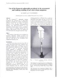
a) Measurement <strong>of</strong> thoracic strap tension<br />
A purpose designed buckle force-transducer<br />
(Fig. 1) is used to measure <strong>the</strong> tension in <strong>the</strong><br />
thoracic strap and may be used in o<strong>the</strong>r straps<br />
such as <strong>the</strong> shoulder strap. The device is small<br />
(35 x 35 x 5mm). The tension in <strong>the</strong> strap can be<br />
measured in situ without modification to <strong>the</strong><br />
<strong>brace</strong> or strap. It is simple to install - by taklng<br />
out <strong>the</strong> removable pin and placing <strong>the</strong> transducer<br />
on <strong>the</strong> thoracic strap <strong>the</strong>n inserting <strong>the</strong><br />
removable pin to <strong>the</strong> original position.<br />
With <strong>the</strong> buckle force-transducer placed on<br />
<strong>the</strong> strap, <strong>the</strong> longitudinal tensile force along <strong>the</strong><br />
strap generates a bending moment on <strong>the</strong> central<br />
beam <strong>of</strong> <strong>the</strong> frame. The relationship between <strong>the</strong><br />
tensile strap force and <strong>the</strong> amount <strong>of</strong> moment
56 M. S. Wong and J. H. Evans<br />
Fig<br />
1 The structure <strong>of</strong> <strong>the</strong> purpose designed buckle<br />
force-transducer.<br />
generated depends on <strong>the</strong> <strong>of</strong>f-set from <strong>the</strong><br />
longitudinal axis <strong>of</strong> <strong>the</strong> strap (Fig. 2). The<br />
amount <strong>of</strong> moment that deforms <strong>the</strong> central<br />
beam is sensed by two stain gauges. The three<br />
metal rods <strong>of</strong> <strong>the</strong> buckle transducer form <strong>the</strong> axis<br />
for thin nylon rollers which help reduce <strong>the</strong><br />
friction between <strong>the</strong> strap and <strong>the</strong> metal rod<br />
during <strong>the</strong> loading and unloading. Ano<strong>the</strong>r<br />
purpose <strong>of</strong> <strong>the</strong> nylon rollers is to increase <strong>the</strong><br />
amount <strong>of</strong> strap <strong>of</strong>f-set which will increase <strong>the</strong><br />
sensitivity <strong>of</strong> <strong>the</strong> transducer without significant<br />
change <strong>of</strong> <strong>the</strong> strap length.<br />
The buckle force-transducer is fitted over <strong>the</strong><br />
strap <strong>of</strong> <strong>the</strong> thoracic pad just behind <strong>the</strong><br />
attachment to <strong>the</strong> anterior outrigger. This is <strong>the</strong><br />
best location for <strong>the</strong> buckle as it is free from<br />
contact with <strong>the</strong> body, thoracic pad and<br />
outrigger. The free length <strong>of</strong> location for <strong>the</strong><br />
transducer is about 35mm.<br />
The transducer is connected as a half-bridged<br />
system with two strain gauges, each furnished to<br />
ei<strong>the</strong>r side <strong>of</strong> <strong>the</strong> buckle frame. The strain<br />
gauges <strong>of</strong> <strong>the</strong> buckle force-transducer are<br />
manufactured by Tokyo Sokki Kenkyujo Co.,<br />
Ltd. and <strong>the</strong>ir specifications are - type: FLA- 3-<br />
23, gauge length: 3mm, gauge resistance:<br />
120±0.3Ω and gauge factor (strain - sensitivity<br />
factor): 2.15.<br />
The whole recording mechanism <strong>of</strong> strap<br />
tension is that <strong>the</strong> buckle force-transducer firstly<br />
transforms <strong>the</strong> mechanical signal (tension force)<br />
into an electric signal which is amplified by a<br />
single conditioner, and <strong>the</strong>n to a XYt recorder<br />
(PM8272, Philips, Ne<strong>the</strong>rlands) which records<br />
<strong>the</strong> signal in <strong>the</strong> form <strong>of</strong> graph plot. The signal<br />
conditioner operates at low voltage (3V) and is<br />
electrically isolated.<br />
An Instron testing machine (Model 1122,<br />
Instron Ltd., High Wycombe, UK) and a strain<br />
gauge meter were used in <strong>the</strong> calibration <strong>of</strong> <strong>the</strong><br />
buckle force-transducer. The buckle forcetransducer<br />
was placed on a double-layer Dacron<br />
strap. The two ends <strong>of</strong> <strong>the</strong> strap were firmly<br />
anchored via special grips to <strong>the</strong> load cell (to<br />
simulate <strong>the</strong> condition as in <strong>the</strong> spinal orthosis).<br />
The strap was loaded in tension from 0 to 300 N<br />
(normal strap tension estimated to be less than<br />
200 N) and <strong>the</strong>n unloaded. The loading and<br />
unloading rate was 10mm/min. Hysteresis was<br />
observed which may be due to <strong>the</strong> elastic<br />
properties <strong>of</strong> <strong>the</strong> Dacron strap, <strong>the</strong> friction<br />
between <strong>the</strong> strap and buckle transducer,<br />
eccentricity in <strong>the</strong> nylon rollers or <strong>the</strong> non-rigid<br />
frame structure. These adverse factors have been<br />
minimised by pre-conditioning <strong>the</strong> Dacron strap,<br />
using concentric nylon rollers and increasing <strong>the</strong><br />
buckle frame rigidity. After <strong>the</strong> above<br />
improvements, <strong>the</strong> degree <strong>of</strong> hysteresis has been<br />
reduced to an acceptable level (Fig. 3).<br />
Fig. 2. Force diagram <strong>of</strong> <strong>the</strong> buckle force-transducer.
<strong>Biomechanical</strong> <strong>evaluation</strong> <strong>of</strong> <strong>the</strong> <strong>Milwaukee</strong> <strong>brace</strong> 57<br />
Fig. 3. Calibration <strong>of</strong> <strong>the</strong> improved buckle force-transducer.<br />
b) Measurement <strong>of</strong> pressure on <strong>the</strong> thoracic pad<br />
The thoracic pad was made <strong>of</strong> thin aluminium<br />
alloy (2024-T3: 1.55mm in thickness), <strong>the</strong><br />
surface facing <strong>the</strong> patient's body was covered<br />
with a s<strong>of</strong>t material (Pelite: 5mm in thickness)<br />
and <strong>the</strong> pad was totally covered with lea<strong>the</strong>r<br />
(bridle light: 2mm in thickness). The thoracic<br />
pad could be bent by bare hands. The bending<br />
rigidity <strong>of</strong> <strong>the</strong> thoracic pad would affect <strong>the</strong><br />
pressure readings, thus two precautions have<br />
been taken. Firstly, <strong>the</strong> thoracic pad was<br />
contoured according to <strong>the</strong> patient's body<br />
contour with no gap in-between. Secondly, <strong>the</strong><br />
contour <strong>of</strong> <strong>the</strong> thoracic pad was traced before<br />
and after <strong>the</strong> pressure measurements to ensure<br />
no distortion <strong>of</strong> <strong>the</strong> pad shape.<br />
The metal neck ring totally em<strong>brace</strong>d <strong>the</strong> neck<br />
but with enough clearance to permit breathing The Dynamic Pressure Monitor has two<br />
and physical exercise. The left and right measuring matrixes (each covering a total area<br />
posterior uprights were aligned by dropping<br />
plumb line from <strong>the</strong> corresponding rivet hole <strong>of</strong><br />
<strong>the</strong> posterior part <strong>of</strong> <strong>the</strong> metal neck ring. The two<br />
<strong>of</strong> 2700 sq mm) and each has four electrohydraulic<br />
sensors (each sensor has a diameter <strong>of</strong><br />
14mm) arranged in a parallelogram shape. The<br />
posterior uprights were 100mm apart (centre-line two matrixes to centre-line) are arranged from on each ei<strong>the</strong>r o<strong>the</strong>r. a horizontal The<br />
positioning <strong>of</strong> <strong>the</strong> pad depended on <strong>the</strong> level <strong>of</strong><br />
<strong>the</strong> scoliotic curve apex. The medial border <strong>of</strong><br />
<strong>the</strong> thoracic pad was placed just medial to <strong>the</strong><br />
medial border <strong>of</strong> <strong>the</strong> right posteriorly upright<br />
and was secured in position by two Dacron<br />
straps attached posteriorly to <strong>the</strong> thoracic pad<br />
with <strong>the</strong> o<strong>the</strong>r ends attached to <strong>the</strong> right posterior<br />
upright. The thoracic pad could be moved freely<br />
in anterior and posterior directions. The design<br />
aimed at giving an anterior-directed force to <strong>the</strong><br />
patient's trunk though <strong>the</strong> posterior part <strong>of</strong> <strong>the</strong><br />
thoracic pad which was fur<strong>the</strong>r reinforced by <strong>the</strong><br />
right posterior upright as <strong>the</strong> thoracic pad came<br />
into contact with <strong>the</strong> posterior upright.<br />
The interface pressure (correcting pressure)<br />
between <strong>the</strong> patient's body and <strong>the</strong> thoracic pad<br />
was measured by <strong>the</strong> Dynamic Pressure Monitor<br />
(DPM 2000C) which was manufactured by<br />
Raymar Ltd., in England. It uses an electrohydraulic<br />
system which can operate at high<br />
sampling rate ( 1 Hz for all sensors) unlike o<strong>the</strong>r<br />
pneumatic-type pressure monitors, which<br />
operate at low speed and can only take one<br />
sample for each sensor at a time. High sampling<br />
rate is required for measuring activities such as<br />
body shifting and deep breathing. The<br />
measurement range is from 0 to 240 mmHg<br />
which is adequate for <strong>the</strong> measurement purpose.<br />
axis or vertical axis (Figs. 4 and 5) and held in<br />
place with adhesive tape on <strong>the</strong> free boundaries<br />
on <strong>the</strong> inner surface <strong>of</strong> <strong>the</strong> thoracic pad for<br />
measuring <strong>the</strong> pressure distribution on different<br />
portions <strong>of</strong> <strong>the</strong> thoracic pad. A Macintosh<br />
computer is required to run <strong>the</strong> s<strong>of</strong>tware <strong>of</strong> <strong>the</strong><br />
DPM 2000C. The collected data can be stored as<br />
data file or expressed as line plots or histograms.<br />
In calibrating <strong>the</strong> Dynamic Pressure Monitor,<br />
three pieces <strong>of</strong> equipment are used. These are a<br />
calibration chamber, sphygmomanometer and<br />
hand pump. The pressure sensors are inserted
58 M. S. Wong and J. H. Evans<br />
0 mmHg to 240 mmHg by using a hand pump<br />
and <strong>the</strong> output from <strong>the</strong> DPM is recorded. The<br />
accuracy <strong>of</strong> <strong>the</strong> reading across <strong>the</strong> whole range is<br />
determined. Adjustment <strong>of</strong> <strong>the</strong> "scale"<br />
potentiometer may be necessary to achieve <strong>the</strong><br />
best overall accuracy. In <strong>the</strong> calibration, it was<br />
found that <strong>the</strong> presence <strong>of</strong> <strong>the</strong> sensor bulbs<br />
would "steal" pressure from <strong>the</strong> areas being<br />
measured if <strong>the</strong> area being measured was a hard<br />
surface. For s<strong>of</strong>t and resiliant surfaces such as<br />
<strong>the</strong> trunk <strong>of</strong> a human being, <strong>the</strong> accuracy <strong>of</strong><br />
measurement could be maintained.<br />
-ig 4. The arrangement <strong>of</strong> <strong>the</strong> pressure sensors on <strong>the</strong><br />
thoracic pad.<br />
into <strong>the</strong> calibration chamber which is a<br />
rectangular wooden box with an opening at one<br />
end. The chamber pressure is increased from<br />
c) Procedure <strong>of</strong> measurement<br />
During measurement <strong>the</strong> pressure sensors<br />
were located in between <strong>the</strong> patient's trunk and<br />
thoracic pad for interface pressure measurement<br />
while <strong>the</strong> buckle-force-transducer was placed on<br />
<strong>the</strong> Dacron thoracic strap for tension<br />
measurement. Before every measurement, <strong>the</strong><br />
buckle transducer was recalibrated again at zero<br />
load and by applying a weight <strong>of</strong> 1 Kg or 9.81 N.<br />
The measurements <strong>of</strong> <strong>the</strong> thoracic pad pressure<br />
and strap tension were recorded simultaneously<br />
over a period <strong>of</strong> time.<br />
The patient was required to wear her spinal<br />
orthosis with <strong>the</strong> above set-up and perform<br />
different lying postures, normal and deep<br />
breathing (in sitting and standing positions) and<br />
also in-<strong>brace</strong> shifting exercises. Measurements<br />
taken in <strong>the</strong>se postures and activities are<br />
commonly performed in daily living, thus, could<br />
reflect <strong>the</strong> actual effect <strong>of</strong> bracing on <strong>the</strong> patient.<br />
Different thoracic strap tensions and pulling<br />
directions were employed as to investigate <strong>the</strong>ir<br />
effect on <strong>the</strong> correctional forces exerted on <strong>the</strong><br />
patient's body by <strong>the</strong> thoracic pad.<br />
Fig. 5. The pressure sensors are firmly stuck to <strong>the</strong><br />
thoracic pad in <strong>the</strong> horizontal axis (above) and vertical<br />
axis (below) while <strong>the</strong> buckle force-transducer is<br />
anchored on <strong>the</strong> anterior part <strong>of</strong> <strong>the</strong> thoracic strap.<br />
Fig. 6. Patient is lying on her left side with <strong>Milwaukee</strong><br />
<strong>brace</strong> which is furnished with buckle force-transducer and<br />
pressure sensors on <strong>the</strong> thoracic strap and thoracic pad<br />
respectively.
<strong>Biomechanical</strong> <strong>evaluation</strong> <strong>of</strong> <strong>the</strong> <strong>Milwaukee</strong> <strong>brace</strong> 59<br />
The protocol <strong>of</strong> measurement is as follows:<br />
1. supine lying;<br />
2. left-side lying; (Fig. 6)<br />
3. right-side lying;<br />
4. prone lying;<br />
5. sitting with normal and deep breathing;<br />
6. standing with normal and deep breathing;<br />
7. standing and shifting away from <strong>the</strong> thoracic<br />
pad; (Fig. 7)<br />
8. standing with normal and deep breathing<br />
(decrease strap tension by one notch down<br />
(2.5cm) from <strong>the</strong> notch as selected on<br />
original fitting;<br />
9. standing with normal and deep breathing<br />
(increase strap tension by one notch up<br />
(2.5cm) from <strong>the</strong> notch as selected on<br />
original fitting;<br />
10. standing with normal and deep breathing<br />
(decrease <strong>the</strong> pulling angle <strong>of</strong> <strong>the</strong> thoracic<br />
strap by shortening <strong>the</strong> outrigger length 8cm<br />
from 12cm);<br />
11. Standing with normal and deep breathing<br />
(increase <strong>the</strong> pulling angle <strong>of</strong> <strong>the</strong> thoracic<br />
strap by leng<strong>the</strong>ning <strong>the</strong> outrigger length to<br />
18cm from 12cm).<br />
Pressure sensors are arranged on horizontal<br />
axis for all <strong>the</strong> above steps. Pressure sensors are<br />
<strong>the</strong>n rearranged on vertical axis and steps 6 and<br />
7 are repeated.<br />
Results and analysis<br />
Nine female patients were selected for this<br />
investigation. Their mean age was 13.25 years<br />
with a range <strong>of</strong> 11.5 to 14.8 years. All <strong>of</strong> <strong>the</strong>m<br />
had right thoracic curves (mean=39°, SD=7°)<br />
and left lumbar curves (mean=33°, SD=6°), and<br />
received <strong>Milwaukee</strong> <strong>brace</strong> treatment for more<br />
than 3 months before <strong>the</strong> start <strong>of</strong> <strong>the</strong><br />
investigation. Their mean flexibility (<strong>the</strong> curve<br />
reduction achieved from lateral bending which<br />
may give some idea about <strong>the</strong> potential benefit<br />
<strong>of</strong> bracing) was 60%±20% in a thoracic curve<br />
and 74%±22% in lumbar curve. After bracing,<br />
<strong>the</strong> curve reduction was 30%±14% in thoracic<br />
region and 42%±11% in lumbar region.<br />
The analysis included <strong>the</strong> correlation between<br />
<strong>the</strong> changes <strong>of</strong> <strong>the</strong> thoracic strap tension and <strong>the</strong><br />
interface pressure <strong>of</strong> <strong>the</strong> thoracic pad as <strong>the</strong><br />
patient performs different lying postures<br />
(supine, left-side, right-side and prone) and<br />
activities (normal and deep breathing in sitting<br />
and standing positions, and shifting exercise),<br />
and <strong>the</strong> change in magnitude and direction <strong>of</strong> <strong>the</strong><br />
correctional force exerted on patient's body by<br />
<strong>the</strong> thoracic pad in different lying postures<br />
(supine, left-side, right-side and prone), different<br />
thoracic strap tension (low, medium and high,<br />
and with different angles (small, medium and<br />
large) <strong>of</strong> pull <strong>of</strong> <strong>the</strong> thoracic strap.<br />
The sampling period was 30 seconds for every<br />
posture or activity. The measurement <strong>of</strong> strap<br />
tension was continuous while <strong>the</strong> sampling rate<br />
<strong>of</strong> <strong>the</strong> Dynamic Pressure Monitor was 1 sample<br />
per second. There were about 5 to 7 breathing<br />
cycles during <strong>the</strong> measurements <strong>of</strong> every posture<br />
or activity.<br />
Fig 7. Patient is doing shifting exercises. She is holding<br />
<strong>the</strong> anterior upright with both hands and moving away<br />
from <strong>the</strong> thoracic pad.<br />
The changes <strong>of</strong> <strong>the</strong> thoracic strap tension and<br />
pressure on <strong>the</strong> thoracic pad induced by<br />
different postures and activities<br />
The mean tension <strong>of</strong> <strong>the</strong> thoracic strap and <strong>the</strong><br />
mean interface pressure (horizontal axis) on <strong>the</strong><br />
thoracic pad <strong>of</strong> <strong>the</strong> nine patients performing<br />
different postures and activities are shown in<br />
Table 1. Their overall mean value <strong>of</strong> strap<br />
tension and pad pressure are 36 (±11, N and 70<br />
(±10) mmHg respectively. There is a high<br />
correlation (mean correlation coefficient = 0.84)<br />
between <strong>the</strong> mean thoracic strap tension and <strong>the</strong><br />
mean interface pressure <strong>of</strong> <strong>the</strong> thoracic pad when<br />
<strong>the</strong> patients performed different postures and<br />
activities.<br />
On <strong>the</strong> horizontal axis <strong>of</strong> <strong>the</strong> thoracic pad, <strong>the</strong><br />
mean interface pressure distribution is higher at<br />
<strong>the</strong> anterior portion (refer to Figure 4) (mean<br />
pressure 98mmHg) that at <strong>the</strong> posterior portion
60 M. S. Wong and J. H. Evans<br />
Table 1. The correlation between <strong>the</strong> mean thoracic pad pressure and <strong>the</strong> mean thoracic strap tension <strong>of</strong> <strong>the</strong> <strong>Milwaukee</strong><br />
<strong>brace</strong> in <strong>the</strong> treatment <strong>of</strong> adolescent idiopathic scoliosis.<br />
(mean pressure 42mmHg) under all activities<br />
and postures except in <strong>the</strong> supine lying posture<br />
as shown in Figure 8.<br />
On <strong>the</strong> vertical axis <strong>of</strong> <strong>the</strong> thoracic pad, <strong>the</strong><br />
mean interface pressure is 37mmHg (44%) at <strong>the</strong><br />
upper portion and 47mmHg (56%) at <strong>the</strong> lower<br />
portion during standing normal and deep<br />
breathing activities (Fig. 9).<br />
The overall mean pad pressure (under all<br />
activities and postures) on <strong>the</strong> horizontal axis<br />
and vertical axis are 70mmHg and 42mmHg<br />
respectively.<br />
The mean values <strong>of</strong> <strong>the</strong> thoracic strap tension<br />
(for <strong>the</strong> nine patients) under different postures<br />
and activities are shown in Table 2.<br />
The effect <strong>of</strong> change <strong>of</strong> <strong>the</strong> thoracic strap tension<br />
on <strong>the</strong> interface pressure distribution on <strong>the</strong><br />
thoracic pad<br />
In this study, <strong>the</strong> tension <strong>of</strong> <strong>the</strong> thoracic strap<br />
was set at three magnitudes: low (19 N), medium<br />
(38 N) and high (49 N). The adjustment <strong>of</strong> strap<br />
tension could be obtained by changing <strong>the</strong> length<br />
<strong>of</strong> <strong>the</strong> Dacron strap (Fig. 10) which was sewn<br />
with Velcro Loop. By altering <strong>the</strong> location <strong>of</strong><br />
attachment <strong>of</strong> <strong>the</strong> Loop to <strong>the</strong> outer surface <strong>of</strong><br />
<strong>the</strong> thoracic pad which was sewn with Velcro<br />
Hook fine adjustment <strong>of</strong> strap tension could be<br />
Fig. 8. The mean interface pressure distribution on <strong>the</strong> thoracic pad (along horizontal axis) during different postures and<br />
activities.
<strong>Biomechanical</strong> <strong>evaluation</strong> <strong>of</strong> <strong>the</strong> <strong>Milwaukee</strong> <strong>brace</strong> 61<br />
Table 2. The mean strap tension under difficult postures<br />
and activities<br />
thoracic pad is more even such that <strong>the</strong> anterior<br />
portion and <strong>the</strong> posterior portion each<br />
experiences similar pressure.<br />
achieved. The pulling angle <strong>of</strong> <strong>the</strong> thoracic strap<br />
remained constant (60°) in <strong>the</strong> process <strong>of</strong><br />
altering <strong>the</strong> magnitude <strong>of</strong> strap tension.<br />
The mean pressure distribution along <strong>the</strong><br />
thoracic pad (horizontal axis) at different<br />
thoracic strap tensions is shown is Figure 11.<br />
The findings indicate that <strong>the</strong> distribution <strong>of</strong><br />
<strong>the</strong> interface pressure along <strong>the</strong> horizontal axis<br />
<strong>of</strong> <strong>the</strong> thoracic pad is similar in <strong>the</strong> mediumtension<br />
and <strong>the</strong> low-tension conditions, i.e., <strong>the</strong><br />
anterior portion <strong>of</strong> <strong>the</strong> thoracic pad exerts<br />
pressure about 3 times higher than that <strong>of</strong> <strong>the</strong><br />
posterior portion. In <strong>the</strong> high tension (shortening<br />
<strong>of</strong> strap length) condition, <strong>the</strong> pressure<br />
distribution along <strong>the</strong> horizontal axis <strong>of</strong> <strong>the</strong><br />
The effect <strong>of</strong> change <strong>of</strong> pulling angle <strong>of</strong> <strong>the</strong><br />
thoracic strap on <strong>the</strong> interface pressure<br />
distribution on <strong>the</strong> thoracic pad<br />
In this study, <strong>the</strong> pulling angle <strong>of</strong> <strong>the</strong> thoracic<br />
strap was set at three magnitudes: low (37°),<br />
medium (60°) and high (83°) by altering <strong>the</strong><br />
length <strong>of</strong> <strong>the</strong> outrigger (Fig. 10). The thoracic<br />
strap tension at 38 N was maintained<br />
(corresponding to <strong>the</strong> activity <strong>of</strong> standing with<br />
normal breathing) in <strong>the</strong> process <strong>of</strong> altering <strong>the</strong><br />
pulling angle.<br />
The mean pressure distribution along <strong>the</strong><br />
thoracic pad (horizontal axis) at different pulling<br />
angles <strong>of</strong> <strong>the</strong> thoracic strap is shown in Figure<br />
12.<br />
The findings show that <strong>the</strong> distribution <strong>of</strong><br />
mean interface pressure between <strong>the</strong> anterior and<br />
posterior portions <strong>of</strong> <strong>the</strong> thoracic pad changes<br />
with <strong>the</strong> pulling angle <strong>of</strong> <strong>the</strong> thoracic strap. In<br />
<strong>the</strong> condition <strong>of</strong> small angle (37°) <strong>of</strong> pull, <strong>the</strong><br />
pressure distribution shows a decrease <strong>of</strong> 7% at<br />
<strong>the</strong> anterior portion as compared with that <strong>of</strong> <strong>the</strong><br />
normal fitting condition. In <strong>the</strong> condition <strong>of</strong><br />
large angle (83°) <strong>of</strong> pull, <strong>the</strong> pressure<br />
distribution shows a decrease <strong>of</strong> 14% as<br />
compared with that <strong>of</strong> <strong>the</strong> normal fitting<br />
condition.<br />
Fig. 9. The mean interface pressure distribution on <strong>the</strong> thoracic pad (along vertical axis) during different postures and<br />
activities.
62 M. S. Wong and J. H. Evans<br />
Fig. 10. Transverse view <strong>of</strong> patient with <strong>Milwaukee</strong> <strong>brace</strong>.<br />
The resultant forces and derotational torques on<br />
<strong>the</strong> patient's trunk<br />
The transverse view <strong>of</strong> a patient with a<br />
<strong>Milwaukee</strong> Brace is shown in Figure 10. The<br />
resultant force and derotational torque exerted<br />
by <strong>the</strong> thoracic pad on <strong>the</strong> patient's trunk could<br />
not be calculated directly unless <strong>the</strong> forces<br />
connecting that pad and <strong>the</strong> structure <strong>of</strong> <strong>the</strong><br />
orthosis were measured. The resultant force<br />
vector can be calculated from pressure<br />
Fig. 11. The mean interface pressure distribution on <strong>the</strong> thoracic pad at different thoracic strap tensions (fixed pulling<br />
angle <strong>of</strong> thoracic strap, 60 degrees).
<strong>Biomechanical</strong> <strong>evaluation</strong> <strong>of</strong> <strong>the</strong> <strong>Milwaukee</strong> <strong>brace</strong> 63<br />
Fig. 12. The mean interface pressure distribution on <strong>the</strong> thoracic pad at different angles <strong>of</strong> pull <strong>of</strong> <strong>the</strong> thoracic strap (fixed<br />
thoracic strap tension).<br />
distribution and <strong>the</strong> known area <strong>of</strong> pad. To<br />
permit <strong>the</strong> calculation <strong>the</strong> following assumptions<br />
are made: no shear forces at <strong>the</strong> interface<br />
between patient's body and thoracic pad, all<br />
thoracic pads having <strong>the</strong> same curvature and<br />
vertical orientation. The location, magnitude and<br />
direction <strong>of</strong> <strong>the</strong> resultant correctional force and<br />
<strong>the</strong> derotational torque exerted on <strong>the</strong> patient's<br />
trunk by <strong>the</strong> thoracic pad at different postures<br />
and activities were calculated from <strong>the</strong> collected<br />
data.<br />
The calculated mean resultant forces exerted<br />
by <strong>the</strong> thoracic pad on <strong>the</strong> patient's trunk in<br />
different lying postures are shown in Figure 13.<br />
The mean resultant forces in <strong>the</strong> supine, leftside,<br />
right - side and prone lying postures were<br />
calculated to be 98, 84, 116 and 55 N<br />
respectively. The mean resultant force in <strong>the</strong><br />
supine lying posture acts on <strong>the</strong> patient's trunk<br />
through <strong>the</strong> anterior part <strong>of</strong> <strong>the</strong> posterior portion<br />
Fig. 13. The resultant forces that <strong>the</strong> thoracic pad exerts on<br />
<strong>the</strong> patient's trunk at different lying postures<br />
Fig 14 The resultant forces that <strong>the</strong> thoracic pad exerts on<br />
<strong>the</strong> patient's trunk at different thoracic strap tensions but<br />
with fixed pulling angle.
64 M. S. Wong and J. H. Evans<br />
<strong>of</strong> <strong>the</strong> thoracic pad at an angle <strong>of</strong> 61° while <strong>the</strong><br />
o<strong>the</strong>r three mean resultant forces act through <strong>the</strong><br />
medical one-third <strong>of</strong> <strong>the</strong> anterior portion <strong>of</strong> <strong>the</strong><br />
thoracic pad with similar angles (42°, 45° and<br />
46°).<br />
The findings indicate that an increase in strap<br />
tension (pulling force) but with fixed pulling<br />
angle will increase <strong>the</strong> magnitude <strong>of</strong> <strong>the</strong><br />
resultant force that <strong>the</strong> thoracic pad exerts on <strong>the</strong><br />
patient's trunk (Fig. 14). The angle <strong>of</strong> <strong>the</strong><br />
resultant force will also increase (move to a<br />
more lateral direction). Simultaneously, <strong>the</strong><br />
point <strong>of</strong> application at <strong>the</strong> thoracic pad will shift<br />
medially. In <strong>the</strong> NN3 and DN3 conditions, <strong>the</strong><br />
point <strong>of</strong> intersection <strong>of</strong> <strong>the</strong> vector axis with <strong>the</strong><br />
pad is at <strong>the</strong> middle part.<br />
The resultant forces that <strong>the</strong> thoracic pad<br />
exerts on <strong>the</strong> patient's trunk at different pulling<br />
angles but with fixed thoracic strap tension are<br />
shown in Figure 15. The findings show that a<br />
smaller pulling angle <strong>of</strong> <strong>the</strong> thoracic strap will<br />
give a more medially directed resultant force,<br />
and vice versa, The points <strong>of</strong> intersection <strong>of</strong> <strong>the</strong><br />
resultant forces are within <strong>the</strong> medial one-third<br />
<strong>of</strong> <strong>the</strong> anterior portion <strong>of</strong> <strong>the</strong> thoracic pad except<br />
under <strong>the</strong> D3 condition. Although, <strong>the</strong>re is a<br />
Fig. 15. The resultant forces that <strong>the</strong> thoracic pad exerts on<br />
<strong>the</strong> patient's trunk at different pulling angles <strong>of</strong> <strong>the</strong><br />
thoracic strap (constant thoracic strap tension).<br />
significant increase in <strong>the</strong> angle <strong>of</strong> <strong>the</strong> resultant<br />
force (from N1=45 to N3=59) as <strong>the</strong> pulling<br />
angle increase from 37° to 83°, <strong>the</strong> point <strong>of</strong><br />
action must be taken into account in considering<br />
<strong>the</strong> derotational torque on <strong>the</strong> vertebrae.<br />
The resultant forces exerted on <strong>the</strong> patient's<br />
body by <strong>the</strong> thoracic pad were resolved into <strong>the</strong><br />
medial-directed component (for curvature<br />
reduction) and <strong>the</strong> anterior-directed component<br />
(for hump reduction). Moreover, <strong>the</strong> resultant<br />
forces could also create a derotational moment<br />
on <strong>the</strong> vertebrae through corresponding ribs. The<br />
derotational moment generated by <strong>the</strong> thoracic<br />
pad was calculated by multiplying <strong>the</strong><br />
magnitude <strong>of</strong> <strong>the</strong> resultant force and <strong>the</strong><br />
perpendicular distance from that force to <strong>the</strong><br />
spinal axis <strong>of</strong> <strong>the</strong> same level. The magnitude,<br />
angle and point <strong>of</strong> action <strong>of</strong> <strong>the</strong> resultant force<br />
must be taken into account in considering <strong>the</strong><br />
derotational torque in <strong>the</strong> vertebrae.<br />
In order to compare <strong>the</strong> effect <strong>of</strong> changes in<br />
posture, tension and pulling angle <strong>of</strong> <strong>the</strong> thoracic<br />
strap in an easier fashion, <strong>the</strong> condition where a<br />
patient with medium thoracic strap tension (38<br />
N), medium pulling angle (60°) and standing<br />
with normal breathing was used as a reference.<br />
The comparison <strong>of</strong> forces and torques at<br />
different postures and activities is shown in<br />
Table 3.<br />
Of <strong>the</strong> four lying postures, <strong>the</strong> patient<br />
experiences least forces and derotational torque<br />
in <strong>the</strong> prone posture. Conversely, <strong>the</strong> patient<br />
experiences <strong>the</strong> largest forces and torques in <strong>the</strong><br />
right side-lying posture.<br />
In <strong>the</strong> activity (DN3) with high thoracic strap<br />
tension, pulling angle <strong>of</strong> 60° and deep breathing,<br />
<strong>the</strong> thoracic pad exerts <strong>the</strong> largest medial and<br />
anterior forces.<br />
In <strong>the</strong> activity (DN2) with medium thoracic<br />
strap tension, pulling angle <strong>of</strong> 60° and deep<br />
breathing, <strong>the</strong> thoracic pad exerts <strong>the</strong> highest<br />
derotational torque.<br />
It was found that <strong>the</strong> average resultant force<br />
increases 45% and <strong>the</strong> average derotational<br />
torque increase 35% from normal breathing to<br />
deep breathing.<br />
Discussion<br />
In this study <strong>the</strong> interface pressure between in<br />
<strong>the</strong> patient's body and thoracic pad, and <strong>the</strong><br />
tension <strong>of</strong> <strong>the</strong> thoracic strap are demonstrated to<br />
change with <strong>the</strong> different postures adopted and<br />
activities undertaken. The changes in <strong>the</strong>se two
<strong>Biomechanical</strong> <strong>evaluation</strong> <strong>of</strong> <strong>the</strong> <strong>Milwaukee</strong> <strong>brace</strong> 65<br />
Table 3. The medial forces, anterior forces and derotational torques exerted on <strong>the</strong> spine through <strong>the</strong> ribs by <strong>the</strong> thoracic<br />
pad during different postures, actitivies, thoracic strap tensions and pulling angles <strong>of</strong> <strong>the</strong> thoracic strap.<br />
parameters are highly correlated (r=0.84).<br />
The mean tension <strong>of</strong> <strong>the</strong> thoracic strap for <strong>the</strong><br />
nine patients is 36± 11 N. The mean interface<br />
pressure exerted on <strong>the</strong> patient's body is<br />
70±10 mmHg. Branemark (1976) pointed out<br />
that pressure sores and ulceration will occur if<br />
pressure is applied on <strong>the</strong> skin over a long period<br />
and over <strong>the</strong> range <strong>of</strong> 40-60 mmHg. Clinically,<br />
patients seldom complain <strong>of</strong> pressure sensitivity<br />
or tissue break down caused by <strong>the</strong> thoracic pad.<br />
This is probably due to <strong>the</strong> fact that although <strong>the</strong><br />
pressure is marginally excessive it can be<br />
relieved intermittently by motion <strong>of</strong> <strong>the</strong> patient's<br />
trunk.<br />
The interface pressure on <strong>the</strong> anterior portion<br />
<strong>of</strong> <strong>the</strong> thoracic pad is about twice that on <strong>the</strong><br />
posterior portion while <strong>the</strong> value on <strong>the</strong> upper<br />
portion is similar to that <strong>of</strong> <strong>the</strong> posterior portion.<br />
Based on this distribution <strong>of</strong> interface pressure<br />
on <strong>the</strong> surface <strong>of</strong> <strong>the</strong> thoracic pad (force = area x<br />
pressure), <strong>the</strong> anterior portion contributes about<br />
50% <strong>of</strong> <strong>the</strong> total correcting force on <strong>the</strong> patient's<br />
body while <strong>the</strong> posterior portion and upper<br />
portion <strong>of</strong> <strong>the</strong> thoracic pad, each exerts about<br />
25% <strong>of</strong> <strong>the</strong> total correcting force.<br />
The mean resultant force exerted on <strong>the</strong><br />
patient's body by <strong>the</strong> thoracic pad is 108±41 N.<br />
Chase et al. (1989) used <strong>the</strong> Oxford Pressure<br />
Monitor to measure <strong>the</strong> forces exerted on a<br />
patient's body by <strong>the</strong> Boston <strong>brace</strong> and found<br />
that <strong>the</strong> mean force exerted by <strong>the</strong> thoracic pad<br />
was 55±18 N. The mean force exerted by <strong>the</strong><br />
thoracic pad <strong>of</strong> <strong>the</strong> <strong>Milwaukee</strong> <strong>brace</strong> was 25 N in<br />
<strong>the</strong> Cochran and Theodore (1969) study, and 38<br />
N in <strong>the</strong> Mulcahy et al. (1973) study. These<br />
large differences may be due to different<br />
techniques <strong>of</strong> <strong>brace</strong> fitting, different methods <strong>of</strong><br />
measurement and different measuring<br />
instruments being employed. The performance<br />
<strong>of</strong> <strong>the</strong> Dynamic Pressure Monitor (DPM) used in<br />
this study was not consistent, even though,<br />
calibration was performed on each occasion<br />
before taking measurements. The results <strong>of</strong> <strong>the</strong><br />
calibration study showed that <strong>the</strong> DPM can<br />
measure true pressure in a hydrostatic situation.<br />
However, <strong>the</strong> results in a plain loading situation<br />
showed that <strong>the</strong> compliance <strong>of</strong> <strong>the</strong> interface<br />
materials to <strong>the</strong> sensor bulb surfaces can<br />
significantly affect <strong>the</strong> response <strong>of</strong> <strong>the</strong> DPM<br />
sensors. Moreover, <strong>the</strong> abnormal thickness <strong>of</strong><br />
<strong>the</strong> sensor bulbs also produces a measurement<br />
artefact at <strong>the</strong> beginning <strong>of</strong> <strong>the</strong> pressurising<br />
process which increases <strong>the</strong> output reading <strong>of</strong><br />
<strong>the</strong> DPM sensors. In order to improve <strong>the</strong><br />
accuracy <strong>of</strong> <strong>the</strong> DPM, two kinds <strong>of</strong> artefacts<br />
must be reduced: 1) <strong>the</strong> artefact produced by <strong>the</strong>
66 M. S. Wong and J. H. Evans<br />
disturbance <strong>of</strong> <strong>the</strong> original interface so that<br />
additional stress is built up on <strong>the</strong> bulbs before<br />
<strong>the</strong> body and <strong>the</strong> thoracic pad totally conformed<br />
to <strong>the</strong> sensor bulb surfaces; 2) <strong>the</strong> artefact<br />
produced by <strong>the</strong> lack <strong>of</strong> compliance <strong>of</strong> <strong>the</strong><br />
body/pad interface to sensor bulb surfaces.<br />
These two kinds <strong>of</strong> artefacts are due to <strong>the</strong> large<br />
uneven thickness (3 to 3.5mm) <strong>of</strong> <strong>the</strong> sensor<br />
bulbs. Therefore, <strong>the</strong> primary manufacturing<br />
improvement would be sensor bulbs with small<br />
and even thickness (
<strong>Biomechanical</strong> <strong>evaluation</strong> <strong>of</strong> <strong>the</strong> <strong>Milwaukee</strong> <strong>brace</strong> 67<br />
patient shifted <strong>the</strong> body away from <strong>the</strong> thoracic<br />
pad. This raises <strong>the</strong> question as to whe<strong>the</strong>r an in<strong>brace</strong><br />
shifting exercise just moves <strong>the</strong> patient's<br />
body away from <strong>the</strong> thoracic pad and <strong>the</strong> forces<br />
generated by <strong>the</strong> hands on <strong>the</strong> anterior upright<br />
are transmitted to <strong>the</strong> trunk through <strong>the</strong><br />
shoulders at <strong>the</strong> level <strong>of</strong> <strong>the</strong> shoulder strap, i.e.,<br />
list to <strong>the</strong> concave side ra<strong>the</strong>r than attempt to<br />
decrease spinal curvature? A fur<strong>the</strong>r<br />
investigation is required to evaluate <strong>the</strong><br />
contribution <strong>of</strong> <strong>the</strong> in-<strong>brace</strong> shifting exercise in<br />
<strong>the</strong> treatment <strong>of</strong> scoliosis.<br />
Conclusion<br />
A biomechanical analysis <strong>of</strong> a conventional<br />
spinal orthosis, <strong>Milwaukee</strong> <strong>brace</strong>, was carried<br />
out. This involved direct and indirect<br />
measurements <strong>of</strong> <strong>the</strong> forces transmitted to <strong>the</strong><br />
body and an analysis <strong>of</strong> <strong>the</strong> corrective effect <strong>the</strong>y<br />
exerted on <strong>the</strong> spine. The principal<br />
measurements were related to thoracic strap<br />
tension and <strong>the</strong> interface pressure distribution<br />
between <strong>the</strong> thoracic pad and <strong>the</strong> patient's body.<br />
There is a high correlations between changes in<br />
<strong>the</strong> thoracic strap tension and <strong>the</strong> interface<br />
pressure <strong>of</strong> <strong>the</strong> thoracic pad in different lying<br />
postures and during various activities. The<br />
change in tension and pulling angle <strong>of</strong> <strong>the</strong><br />
thoracic strap can vary in magnitude, direction<br />
and line <strong>of</strong> action <strong>of</strong> <strong>the</strong> resultant force which <strong>the</strong><br />
thoracic pad exerts on <strong>the</strong> patient's body. A<br />
knowledge <strong>of</strong> <strong>the</strong> magnitude, direction and line<br />
<strong>of</strong> action <strong>of</strong> <strong>the</strong> resultant force can be used to<br />
evaluate <strong>the</strong> accuracy <strong>of</strong> fit and <strong>the</strong> efficiency <strong>of</strong><br />
support, <strong>the</strong> progress <strong>of</strong> treatment and <strong>the</strong><br />
effectiveness <strong>of</strong> various design modifications.<br />
REFERENCES<br />
ANDRE N (1978). L'orthopaedia, ou, l'art de prévenir et<br />
de corriger dans les enfants deformite a du corps. In:<br />
Scoliosis and o<strong>the</strong>r spinal deformities/by JH Moe, RB<br />
Winter, DS Bradford, JE Lonstein. - Philadelphia: WB<br />
Saunders.<br />
ANDRIACCHI TP, SHULTZ AB, BELYTSCHKO TB, DEWALD<br />
RL (1976). <strong>Milwaukee</strong> <strong>brace</strong> correction <strong>of</strong> idiopathic<br />
scoliosis: a biomechanical analysis and retrospective<br />
study. J Bone Joint Surg 58A, 806-815.<br />
BLOUNT WP, MOE JH (1980). <strong>Milwaukee</strong> <strong>brace</strong>. -<br />
Baltimore: Williams & Wilkins.<br />
BRADFORD DS, LONSTEIN JE, MOE JH, OGILVIE JW,<br />
WINTER RB (1987). Scoliosis and o<strong>the</strong>r spinal<br />
deformities. - Philadelphia: Saunders Co.<br />
BRANEΜARK PI (1976). Microvascular function <strong>of</strong><br />
reduced flow rates. In: Bed sore biomechanics. -<br />
London: Macmillan Co p.63-68<br />
BUNCH WH, PATWARDHAm AG (1989). Scoliosis: making<br />
clinical decisions. - St. Louis: CV Mosby.<br />
CHASE AP, BADER DL, HOUGTON GR (1989). The<br />
biomechanical effectiveness <strong>of</strong> <strong>the</strong> Boston <strong>brace</strong> in <strong>the</strong><br />
management <strong>of</strong> adolescent idiopathic scoliosis. Spine<br />
14, 636-642.<br />
COCHRAN GVB, THEODORE RW (1969). The external<br />
forces in correction <strong>of</strong> idiopathic scoliosis (abstract).<br />
J Bone Joint Surg 51A, 201.<br />
GALANTE J, SHULTZ AB, DEWALD RL, RAY RD (1970).<br />
Forces acting on <strong>the</strong> <strong>Milwaukee</strong> <strong>brace</strong> on patients<br />
undergoing treatment for idiopathic scoliosis. J Bone<br />
Joint Surg 52A, 498-506.<br />
LAURNEN EL, TUPPER JW, MULLEN MP (1983). The<br />
Boston <strong>brace</strong> in thoracic scoliosis: a preliminary report<br />
Spine 8, 388-395.<br />
LONSTEIN JE, CARLSON JM (1984). The prediction <strong>of</strong><br />
curve progression in untreated idiopathic scoliosis<br />
during growth. J Bone Joint Surg 66A, 1061-1071.<br />
MULACHAY T, GALANTE J, DEWALD R (1973). A followup<br />
study <strong>of</strong> forces acting on <strong>the</strong> <strong>Milwaukee</strong> <strong>brace</strong> on<br />
patients undergoing treatment for idiopathic scoliosis.<br />
Clin Orthop 93, 53-68.<br />
WILLNER S (1984). Effect <strong>of</strong> <strong>the</strong> Boston thoracic <strong>brace</strong> on<br />
<strong>the</strong> frontal and sagittal curves <strong>of</strong> <strong>the</strong> spine. Acta Orthop<br />
Scand 55, 457-450.<br />
WINTER RB, LONSTEIN JE, DROGT J, NOREN CA (1986).<br />
The effectiveness <strong>of</strong> bracing in <strong>the</strong> non-operative<br />
treatment <strong>of</strong> idiopathic scoliosis. Spine 11, 790-791.<br />
WINTER RB, CARLSON JM (1977). Modern orthotics for<br />
spinal deformities. Clin Orthop 126, 74-86.<br />
WYNARSKY GT, SHULTZ AB, (1990). Trunk muscle<br />
activities in <strong>brace</strong>d scoliosis patients. Spine 14, 1283-<br />
1287.