Biomechanical evaluation of the Milwaukee brace
Biomechanical evaluation of the Milwaukee brace
Biomechanical evaluation of the Milwaukee brace

Create successful ePaper yourself
Turn your PDF publications into a flip-book with our unique Google optimized e-Paper software.
<strong>Biomechanical</strong> <strong>evaluation</strong> <strong>of</strong> <strong>the</strong> <strong>Milwaukee</strong> <strong>brace</strong> 57<br />
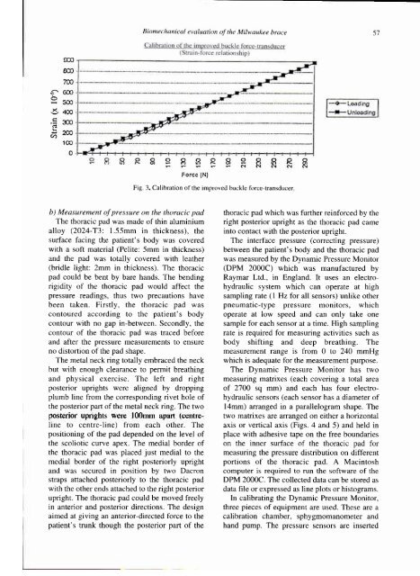
Fig. 3. Calibration <strong>of</strong> <strong>the</strong> improved buckle force-transducer.<br />
b) Measurement <strong>of</strong> pressure on <strong>the</strong> thoracic pad<br />
The thoracic pad was made <strong>of</strong> thin aluminium<br />
alloy (2024-T3: 1.55mm in thickness), <strong>the</strong><br />
surface facing <strong>the</strong> patient's body was covered<br />
with a s<strong>of</strong>t material (Pelite: 5mm in thickness)<br />
and <strong>the</strong> pad was totally covered with lea<strong>the</strong>r<br />
(bridle light: 2mm in thickness). The thoracic<br />
pad could be bent by bare hands. The bending<br />
rigidity <strong>of</strong> <strong>the</strong> thoracic pad would affect <strong>the</strong><br />
pressure readings, thus two precautions have<br />
been taken. Firstly, <strong>the</strong> thoracic pad was<br />
contoured according to <strong>the</strong> patient's body<br />
contour with no gap in-between. Secondly, <strong>the</strong><br />
contour <strong>of</strong> <strong>the</strong> thoracic pad was traced before<br />
and after <strong>the</strong> pressure measurements to ensure<br />
no distortion <strong>of</strong> <strong>the</strong> pad shape.<br />
The metal neck ring totally em<strong>brace</strong>d <strong>the</strong> neck<br />
but with enough clearance to permit breathing The Dynamic Pressure Monitor has two<br />
and physical exercise. The left and right measuring matrixes (each covering a total area<br />
posterior uprights were aligned by dropping<br />
plumb line from <strong>the</strong> corresponding rivet hole <strong>of</strong><br />
<strong>the</strong> posterior part <strong>of</strong> <strong>the</strong> metal neck ring. The two<br />
<strong>of</strong> 2700 sq mm) and each has four electrohydraulic<br />
sensors (each sensor has a diameter <strong>of</strong><br />
14mm) arranged in a parallelogram shape. The<br />
posterior uprights were 100mm apart (centre-line two matrixes to centre-line) are arranged from on each ei<strong>the</strong>r o<strong>the</strong>r. a horizontal The<br />
positioning <strong>of</strong> <strong>the</strong> pad depended on <strong>the</strong> level <strong>of</strong><br />
<strong>the</strong> scoliotic curve apex. The medial border <strong>of</strong><br />
<strong>the</strong> thoracic pad was placed just medial to <strong>the</strong><br />
medial border <strong>of</strong> <strong>the</strong> right posteriorly upright<br />
and was secured in position by two Dacron<br />
straps attached posteriorly to <strong>the</strong> thoracic pad<br />
with <strong>the</strong> o<strong>the</strong>r ends attached to <strong>the</strong> right posterior<br />
upright. The thoracic pad could be moved freely<br />
in anterior and posterior directions. The design<br />
aimed at giving an anterior-directed force to <strong>the</strong><br />
patient's trunk though <strong>the</strong> posterior part <strong>of</strong> <strong>the</strong><br />
thoracic pad which was fur<strong>the</strong>r reinforced by <strong>the</strong><br />
right posterior upright as <strong>the</strong> thoracic pad came<br />
into contact with <strong>the</strong> posterior upright.<br />
The interface pressure (correcting pressure)<br />
between <strong>the</strong> patient's body and <strong>the</strong> thoracic pad<br />
was measured by <strong>the</strong> Dynamic Pressure Monitor<br />
(DPM 2000C) which was manufactured by<br />
Raymar Ltd., in England. It uses an electrohydraulic<br />
system which can operate at high<br />
sampling rate ( 1 Hz for all sensors) unlike o<strong>the</strong>r<br />
pneumatic-type pressure monitors, which<br />
operate at low speed and can only take one<br />
sample for each sensor at a time. High sampling<br />
rate is required for measuring activities such as<br />
body shifting and deep breathing. The<br />
measurement range is from 0 to 240 mmHg<br />
which is adequate for <strong>the</strong> measurement purpose.<br />
axis or vertical axis (Figs. 4 and 5) and held in<br />
place with adhesive tape on <strong>the</strong> free boundaries<br />
on <strong>the</strong> inner surface <strong>of</strong> <strong>the</strong> thoracic pad for<br />
measuring <strong>the</strong> pressure distribution on different<br />
portions <strong>of</strong> <strong>the</strong> thoracic pad. A Macintosh<br />
computer is required to run <strong>the</strong> s<strong>of</strong>tware <strong>of</strong> <strong>the</strong><br />
DPM 2000C. The collected data can be stored as<br />
data file or expressed as line plots or histograms.<br />
In calibrating <strong>the</strong> Dynamic Pressure Monitor,<br />
three pieces <strong>of</strong> equipment are used. These are a<br />
calibration chamber, sphygmomanometer and<br />
hand pump. The pressure sensors are inserted