Instruction Manual - OFI Testing Equipment, Inc.
Instruction Manual - OFI Testing Equipment, Inc.
Instruction Manual - OFI Testing Equipment, Inc.

You also want an ePaper? Increase the reach of your titles
YUMPU automatically turns print PDFs into web optimized ePapers that Google loves.
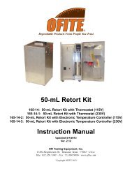
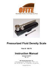
BLP-530 Gas Porosimeter<br />
Part No. 127-20<br />
<strong>Instruction</strong> <strong>Manual</strong><br />
Updated 8/28/2012<br />
Ver. 3.2<br />
<strong>OFI</strong> <strong>Testing</strong> <strong>Equipment</strong>, <strong>Inc</strong>.<br />
11302 Steeplecrest Dr. · Houston, Texas · 77065 · U.S.A.<br />
Tele: 832.320.7300 · Fax: 713.880.9886 · www.ofite.com<br />
©<br />
Copyright <strong>OFI</strong>TE 2011
Table of<br />
Contents<br />
Intro.......................................................................................................2<br />
Description...........................................................................................2<br />
Features................................................................................................2<br />
Components.........................................................................................2<br />
Setup.....................................................................................................3<br />
Operation..............................................................................................4<br />
<strong>Testing</strong> Without a Vacuum ...............................................................4<br />
<strong>Testing</strong> Other Samples ....................................................................5<br />
<strong>Testing</strong> With a Vacuum ....................................................................6<br />
Calculations .........................................................................................7<br />
Maintenance.........................................................................................9<br />
Calibrating the Porosimeter Constants (V1 and V2) .......................9<br />
<strong>OFI</strong>TE, 11302 Steeplecrest Dr., Houston, TX 77065 USA / Tel: 832-320-7300 / Fax: 713-880-9886 / www.ofite.com 1
Intro<br />
The <strong>OFI</strong>TE BLP-530 Gas Porosimeter was designed to rapidly and accurately<br />
measure the effective porosity of a core sample. Porosity is defined<br />
as the percentage of void within a solid media. Effective porosity is the<br />
percentage of void within a solid media in which the pore spaces are interconnected.<br />
It is imperative to accurately measure the effective porosity of<br />
a petroleum reservoir when estimating the amount of recoverable oil within<br />
a producing formation. The BLP-530 was engineered to precisely measure<br />
the effective porosity of a core sample.<br />
Description<br />
A sample is placed into an airtight sample holder and pressure is applied to<br />
a reservoir of known volume. After the pressure has stabilized, a valve is<br />
opened, which permits the gas within the reservoir to expand into the sample<br />
holder. After equilibrium is reached, the new pressure of the system is<br />
measured and recorded. The effective porosity of the core specimen may<br />
be calculated by the use of Boyle’s Law (P 1 V 1 = P 2 V 2 ) in conjunction with<br />
the bulk volume of the sample. The variables V 1 and V 2 are constants,<br />
which are dependent upon the geometry of the unit and the effective porosity<br />
of the core.<br />
Features<br />
- Precision regulator for accurate pressure control<br />
- Digital display of pressure<br />
- Vacuum gauge and connection port for evacuation<br />
- Lock in feature allows for rapid measurements of samples<br />
- Unit is compact and virtually maintenance free<br />
- Calibration sample included with unit<br />
- Air relief valve prevents over pressurization<br />
- Can test core samples 1.5" (3.81 cm) in diameter by 2" (5.08 cm) long<br />
- Size: 24" × 22" × 20" (61 × 55.9 × 50.8 cm)<br />
- Weight: 150 lbs (68.1 kg)<br />
Requirements:<br />
- Helium or Nitrogen source (500 PSI / 3,448 kPa minimum)<br />
- 220 Volt, 50 Hz power source<br />
Components<br />
#120-27-004 DP-15 Diaphragm (0 - 200 PSI)<br />
#127-00-262 Valve<br />
#127-20-004 O-ring for Test Cell<br />
#127-20-020 Calibration Block<br />
<strong>OFI</strong>TE, 11302 Steeplecrest Dr., Houston, TX 77065 USA / Tel: 832-320-7300 / Fax: 713-880-9886 / www.ofite.com 2
Setup<br />
1. Carefully remove the instrument from the wooden crate and place it on<br />
a countertop.<br />
2. Connect a nitrogen air supply (500 PSI / 3,448 kPa) to the port on the<br />
back of the instrument panel.<br />
3. Connect the vacuum pump to the port located on the front panel with<br />
the hoses and connectors supplied with the unit.<br />
Note<br />
<strong>OFI</strong>TE uses ¼" NPT female connections.<br />
4. Make sure the unit is turned off. Plug the unit into a grounded electrical<br />
outlet. The electrical socket is located on the back of the unit. A<br />
120/220 VAC, 50/60 Hz power source is recommended. Apply electrical<br />
power to the vacuum pump in the same manner.<br />
5. The o-ring (Part #127-22) contained within the sample holder should be<br />
periodically checked and replaced when needed. Applying a thin film of<br />
typical bearing grease to the o-ring will facilitate installation and prolong<br />
the life of the o-ring.<br />
Eurotherm<br />
Indicator<br />
Pressure Gauge<br />
Power Switch<br />
Regulator<br />
Sample Holder<br />
P1 Lock In<br />
Three-Way Valve<br />
Vacuum Port<br />
P2 Test Valve<br />
<strong>OFI</strong>TE, 11302 Steeplecrest Dr., Houston, TX 77065 USA / Tel: 832-320-7300 / Fax: 713-880-9886 / www.ofite.com 3
Operation<br />
<strong>Testing</strong> Without a<br />
Vacuum<br />
1. Before starting a test, place all valves in the vertical position. Make<br />
sure the regulator on the front panel is rotated fully counter-clockwise.<br />
2. Turn the unit on and allow it to warm up for 5 to 10 minutes. After the<br />
unit warms up, the display should read zero.<br />
3. Measure and record the diameter and length of the core with the<br />
calipers included with the unit.<br />
4. Unscrew the sample holder and insert the core specimen. Screw the<br />
sample holder back into place just until it stops.<br />
5. Turn the “P2 Test” valve to the “Off” position.<br />
6. Rotate the regulator clockwise until the pressure reads approximately<br />
180 PSI (1,242 kPa).<br />
7. Turn the “P1 Lock In” valve to the “Off” position.<br />
8. Allow P 1 to stabilize and record this value.<br />
Sample Holder<br />
O-ring<br />
<strong>OFI</strong>TE, 11302 Steeplecrest Dr., Houston, TX 77065 USA / Tel: 832-320-7300 / Fax: 713-880-9886 / www.ofite.com 4
9. Make sure the three-way valve is in the “TEST” position.<br />
10. Allow the gas to expand into the test chamber by turning the “P2 Test”<br />
valve to the vertical position.<br />
11. Allow P 2 to stabilize and record this value.<br />
12. The values P 1 , P 2 , D (diameter), and L (length) can be inserted into the<br />
Porosimeter Spreadsheet and the sample porosity will be calculated<br />
automatically.<br />
13. Turn the three-way valve to “VENT” and remove the sample.<br />
Operation<br />
<strong>Testing</strong> Other Samples<br />
Once the unit has been set up, it is easy to test numerous specimens. To<br />
test numerous specimens, follow the procedures listed below. It is recommended<br />
to label and measure each core before performing a test.<br />
1. Place a new specimen into the sample holder and screw it in just until it<br />
stops.<br />
2. Place the three-way valve into the “TEST” position.<br />
3. Return the “P2 Test” valve to the “OFF” position.<br />
4. Turn the “P1 Lock In” valve to the vertical position for a few seconds.<br />
Return the “P1 Lock In” valve to the “OFF” position. Allow the pressure<br />
to stabilize and record P 1 .<br />
5. Allow the gas to expand into the test chamber by turning the “P2 Test”<br />
valve to the vertical position. After stabilization, record P 2 .<br />
6. Place the three-way valve into the “VENT” position and remove the<br />
core specimen.<br />
7. Repeat steps 1 - 6 until all of the specimens have been tested.<br />
<strong>OFI</strong>TE, 11302 Steeplecrest Dr., Houston, TX 77065 USA / Tel: 832-320-7300 / Fax: 713-880-9886 / www.ofite.com 5
Operation<br />
<strong>Testing</strong> With a Vacuum<br />
!<br />
Important<br />
When core specimens have very low porosity (less than 2%), it may be<br />
necessary to fully evacuate a core using the supplied vacuum pump before<br />
conducting a porosity test.<br />
Only use the vacuum to evacuate core samples of very low porosity.<br />
Using the vacuum on core samples with normal porosity can produce<br />
inaccurate readings.<br />
1. Follow steps 1 through 4 on page 4 to prepare the unit and sample core<br />
for testing.<br />
2. Make sure the “P1 Lock In” valve is in the vertical position, the “P2<br />
Test” valve is in the “OFF” position and the three-way valve is in the<br />
“Vacuum” position.<br />
3. Turn the vacuum pump on and evacuate the core until the vacuum<br />
gauge shows a steady reading.<br />
4. Switch the three-way valve to the “Test” position.<br />
5. Proceed with testing as normal.<br />
<strong>OFI</strong>TE, 11302 Steeplecrest Dr., Houston, TX 77065 USA / Tel: 832-320-7300 / Fax: 713-880-9886 / www.ofite.com 6
Calculations<br />
In the equations below, V 1 and V 2 are constants. Each Porosimeter has<br />
different V 1 and V 2 values. The values for each unit are located on the<br />
nameplate attached to the back of the unit. See the “Calibrating the<br />
Porosimeter Constants” section on page 10.<br />
Core Bulk Volume V B =<br />
πD 2 L<br />
4<br />
Where: V B = Bulk Volume<br />
D = Diameter<br />
L = Length<br />
Core Grain Volume V G = V 2 - V 3<br />
Where: V G = Core Grain Volume<br />
V 2 = Constant of the Porosimeter<br />
V 3 = P 1 V 1<br />
Where: P 1 = Initial Pressure Value<br />
P 2 = Final Pressure Value and Expansion<br />
V 1 = Constant of Porosimeter<br />
Porosity (Φ) Φ =<br />
Example:<br />
(V B - V G ) 100<br />
V B<br />
P 2<br />
P 1 V 1<br />
L = 2.65 cm D = 2.54 cm<br />
P 1 = 182.6 PSI P 2 = 71.5 PSI<br />
V 1 = 58.64 cc V 2 = 161.18 cc<br />
V B =<br />
πD 2 L π2.54 2 (2.65)<br />
=<br />
4<br />
4<br />
= 13.43 cc<br />
V 3 =<br />
182.6 (58.64)<br />
=<br />
P 2 71.5<br />
= 149.76 cc<br />
V G = V 2 - V 3 = 161.18 - 149.76 = 11.42 cc<br />
Φ =<br />
(V B - V G ) 100 (13.43 - 11.42) 100<br />
= =<br />
V B 13.43<br />
14.93%<br />
<strong>OFI</strong>TE, 11302 Steeplecrest Dr., Houston, TX 77065 USA / Tel: 832-320-7300 / Fax: 713-880-9886 / www.ofite.com 7
A spreadsheet in MS Excel format has been provided to simplify the calculation<br />
of porosity.<br />
1. Enter the length and diameter of the core into the cells outlined by the<br />
red boxes.<br />
2. Enter P 1 and P 2 into the appropriate cells.<br />
3. Bulk volume, grain volume, and effective porosity are automatically calculated.<br />
<strong>OFI</strong>TE, 11302 Steeplecrest Dr., Houston, TX 77065 USA / Tel: 832-320-7300 / Fax: 713-880-9886 / www.ofite.com 8
Maintenance<br />
Calibrating the<br />
Porosimeter Constants<br />
(V 1 and V 2 )<br />
The constants V 1 and V 2 have been calculated for each new Porosimeter.<br />
These values are located on the nameplate attached to the back of the<br />
Porosimeter. In the event that any plumbing or fittings are replaced, it will<br />
be necessary to recalibrate the Porosimeter. This is achieved by solving<br />
two equations simultaneously.<br />
First, a pressure (P 1 ) is exerted on the volume of the system (V 1 ) with the<br />
“P2 Test” valve closed. Then this valve is opened and the gas is allowed to<br />
expand into the empty sample chamber, which creates a new pressure (P 2 )<br />
that is a function of the entire volume of the system (V 2 ).<br />
Secondly, the above procedure is repeated with a calibration block (included<br />
with each unit) of known volume (V B ) inserted into the sample chamber.<br />
This yields pressure (P 3 ) from the system with the “P2 Test” valve closed<br />
and the pressure (P 4 ) from the expansion of the gas into the sample chamber<br />
with a block of known volume. Simultaneously solving the two equations<br />
in mathematical form is stated below.<br />
From Boyle’s Law P 1 V 1 = P 2 V 2<br />
Empty Reservoir<br />
Reservoir with Block<br />
1. V 2 = V 1 + V R V 2 = V 1 + (V R - V B )<br />
Applying Boyle’s Law<br />
2. P 1 V 1 = P 2 V 1 + P 2 V R P 3 V 1 = P 4 V 1 + (P 4 V R - P 4 V B )<br />
Combining the equations and solving for V1 yields:<br />
3. V 1 = P 2 V B P 4<br />
P 4 P 1 - P 2 P 3<br />
Once V 1 is obtained, V R can be calculated from equation 2.<br />
4. V R =<br />
P 1 V 1 - P 2 V 1<br />
P 2<br />
Knowing V 1 and V R allows the calculation of V 2 from equation 1.<br />
<strong>OFI</strong>TE, 11302 Steeplecrest Dr., Houston, TX 77065 USA / Tel: 832-320-7300 / Fax: 713-880-9886 / www.ofite.com 9