Complete Half-Area Filter Press - OFI Testing Equipment, Inc.
Complete Half-Area Filter Press - OFI Testing Equipment, Inc.
Complete Half-Area Filter Press - OFI Testing Equipment, Inc.

You also want an ePaper? Increase the reach of your titles
YUMPU automatically turns print PDFs into web optimized ePapers that Google loves.
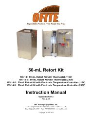
<strong>Complete</strong> <strong>Half</strong>-<strong>Area</strong> <strong>Filter</strong> <strong>Press</strong><br />
Part No. 140-60<br />
Instruction Manual<br />
Updated 11/18/2010<br />
Ver. 2.1<br />
<strong>OFI</strong> <strong>Testing</strong> <strong>Equipment</strong>, <strong>Inc</strong>.<br />
11302 Steeplecrest Dr. · Houston, Texas · 77065 · U.S.A.<br />
Tele: 832.320.7300 · Fax: 713.880.9886 · www.ofite.com<br />
©<br />
Copyright <strong>OFI</strong>TE 2012
Table of<br />
Contents<br />
Intro....................................................................................................2<br />
Components......................................................................................3<br />
Operation ..........................................................................................4<br />
Maintenance......................................................................................6<br />
<strong>OFI</strong>TE, 11302 Steeplecrest Dr., Houston, TX 77065 USA / Tel: 832-320-7300 / Fax: 713-880-9886 / www.ofite.com 1
Intro<br />
The <strong>OFI</strong>TE <strong>Half</strong> <strong>Area</strong> <strong>Filter</strong> <strong>Press</strong>, or Mini-press, consists of a modified lowpressure<br />
regulator with a CO 2 bulb pressurizing assembly and a filtration<br />
cell body. A rubber diaphragm boot contains the fluid and separates it from<br />
the pressurizing gas. This enables the unit to be operated while inverted,<br />
which negates the effect of particles settling on the filter medium prior to<br />
pressurization. The top edge of the boot acts as a gasket to provide a seal<br />
to the filter paper and the end cap.<br />
As the name implies, the filtration area is only half the API standard, 7.1 ±<br />
0.1 in 2 (4580 ± 60 mm 2 ) so all filtrate volumes must be doubled in order to<br />
comply with standard low-pressure filtration analyses. The compactness of<br />
the <strong>OFI</strong>TE Mini-press allows it to be easily carried in all of the field kits, and<br />
it provides an accurate means of determining the filtration and wall-building<br />
characteristics of a drilling fluid.<br />
<strong>OFI</strong>TE, 11302 Steeplecrest Dr., Houston, TX 77065 USA / Tel: 832-320-7300 / Fax: 713-880-9886 / www.ofite.com 2
Components<br />
#140-60-01 O-ring for Bleeder Valve; Qty: 3<br />
#140-60-03 C-ring for Bleeder Valve; Qty: 2<br />
#140-60-04 E-ring for Base Cap<br />
#140-60-05 Sample Boot<br />
#140-60-06 Spring Housing Cap<br />
#140-60-09 Gasket<br />
#140-60-10 Friction Washer<br />
#140-60-13 Spring Button<br />
#140-60-14 Adjusting Spring<br />
#140-60-15 T-screw<br />
#140-60-16 Spring for Pop Valve<br />
#141-20 Frog Bracket<br />
#141-21 Wall Bracket<br />
#142-38 Nozzle<br />
#142-41 Gland<br />
#142-46 Valve Spring<br />
#142-47 Seat Assembly<br />
#142-48 Diaphragm Assembly<br />
#142-49 Slip Ring<br />
#143-00-6 ¼" Stainless Steel Ball for Airco Regulator<br />
#143-01-1 200-PSI Gauge; 1/8" Back<br />
#143-02-10 CO 2 Puncture Head Assembly<br />
#143-03 Barrel for CO 2 Cartridge<br />
#153-18 Graduated Cylinder; 10 mL x 2/10 mL; Glass<br />
#170-19 <strong>Filter</strong> Paper 2½" (6.335 cm); Specially Hardened for <strong>Filter</strong><br />
<strong>Press</strong>es<br />
#170-23 60 Mesh Screen<br />
Optional:<br />
#140-84 <strong>Filter</strong> <strong>Press</strong> Stand<br />
#140-60-SP Spare Parts for #140-60:<br />
#140-60-01 O-ring for Bleeder Valve; Qty: 4<br />
#140-60-03 C-ring for Bleeder Valve; Qty: 2<br />
#140-60-04 E-ring for Base Cap; Qty: 2<br />
#140-60-05 Sample Boot<br />
#140-60-12 Screen Retainer with Filtrate Tube<br />
#140-60-16 Spring for Pop Valve<br />
#140-84 Stand<br />
#143-02-13 O-ring for Puncture Pin Holder; CO 2 Cartridge; Qty: 4<br />
#143-02-14 O-ring for Puncture Pin Holder Assembly; Qty: 4<br />
#143-05 *CO 2 Bulbs; EZ Puncture; Package of 10 (8 Gram) (UN<br />
#1013); Qty: 30<br />
#143-19 Repair Kit for Victor Regulator<br />
#153-18 Graduated Cylinder; 10 mL x 2/10 mL; Glass; Qty: 2<br />
#153-40 Pipet; 10 mL x 1/10 mL; Glass; Qty: 4<br />
#170-19 <strong>Filter</strong> Paper 2½" (6.335 cm); Specially Hardened for<br />
<strong>Filter</strong> <strong>Press</strong>es; Qty: 5<br />
<strong>OFI</strong>TE, 11302 Steeplecrest Dr., Houston, TX 77065 USA / Tel: 832-320-7300 / Fax: 713-880-9886 / www.ofite.com 3
Operation<br />
1. Unscrew the cell cap from the cell body.<br />
2. Seat the rubber boot inside the cell to ensure a tight seal.<br />
Rubber Boot<br />
!<br />
Important<br />
3. Fill the rubber boot with test fluid. Do not fill to closer than ¼" from the<br />
top of the boot. Be careful not to spill any fluid on the edge of the boot.<br />
Exercise care when handling the cell when it is filled with fluid so<br />
that the valve is not accidentally opened before the cell cap is<br />
screwed into place.<br />
4. Place a sheet of filter paper across the top of the boot.<br />
5. Hand tighten the cell cap firmly.<br />
6. Mount the cell assembly on a wall bracket and place a 10-mL graduated<br />
cylinder under the filtrate tube to catch the filtrate.<br />
An optional stand is also available to provide more convenient, portable<br />
access to the filter press.<br />
<strong>OFI</strong>TE, 11302 Steeplecrest Dr., Houston, TX 77065 USA / Tel: 832-320-7300 / Fax: 713-880-9886 / www.ofite.com 4
Regulator<br />
T-screw<br />
Relief Valve<br />
<strong>Press</strong>ure<br />
Gauge<br />
7. Push the Relief Valve forward toward the front of the unit. Place a CO 2<br />
(sold separately) cartridge into the cartridge barrel and screw it onto the<br />
filter press body until the cartridge punctures.<br />
8. <strong>Press</strong>urize the cell by pushing the relief valve toward the back of the<br />
cell and rapidly screwing the regulator T-screw into the regulator so that<br />
100 ± 5 PSI (690 ± 35 kPa) is applied in 30 seconds or less to the cell<br />
body. The test time period begins when pressure is applied.<br />
9. Record the volume of filtrate collected to the nearest 0.1 cm 3 as the API<br />
filtrate. Correct the filtrate volume collected to a filter area of 7.1 in 2 by<br />
multiplying the volume by 2. Also record the temperature of the fluid,<br />
the time of the test, and the pressure used.<br />
10. When the test is complete, release the pressure inside the test cell by<br />
unscrewing the T-screw on the regulator. When the pressure gauge<br />
reads 0 PSI, push the relief valve forward.<br />
11. You can now remove the end cap. Save the filtrate for chemical testing.<br />
12. Be very careful to save the filter paper without disturbing the cake.<br />
Gently wash the filter cake on the paper and measure the thickness to<br />
the nearest 1 ⁄32" (9.8 mm). Report cake characteristics as hard, spongy,<br />
firm, etc.<br />
13. To perform additional tests, simply refill the rubber boot with new test<br />
fluid and tighten the cap in place.<br />
14. Then, push the relief valve toward the back of the unit to pressurize the<br />
cell and initiate the test.<br />
15. When you are finished testing, unscrew the cartridge barrel and discard<br />
the spent cartridge.<br />
<strong>OFI</strong>TE, 11302 Steeplecrest Dr., Houston, TX 77065 USA / Tel: 832-320-7300 / Fax: 713-880-9886 / www.ofite.com 5
Maintenance<br />
1. If the pressure gauge registers insufficient pressure after the T-screw<br />
has been screwed into the regulator, the CO 2 bulb is probably exhausted.<br />
Push the relief valve toward the front of the cell and return the T-<br />
screw to its maximum outward position. Remove the barrel from the<br />
pressure unit and discard the spent bulb. Place a new CO 2 bulb into<br />
the barrel and screw the barrel back into the puncture assembly. Do<br />
not over tighten, as this will result in a loss of CO 2 gas.<br />
2. Thoroughly clean and dry the filter press unit immediately after each<br />
use.<br />
3. Protect CO 2 bulbs from sunlight and other sources of heat.<br />
4. Lubricate the bleeder valve o-rings with a film of silicone grease for<br />
extended life.<br />
<strong>OFI</strong>TE, 11302 Steeplecrest Dr., Houston, TX 77065 USA / Tel: 832-320-7300 / Fax: 713-880-9886 / www.ofite.com 6
T-Screw (#140-60-15)<br />
Spring Housing Cap with Bushing<br />
(#140-60-06)<br />
Spring Button (#140-60-13)<br />
Adjusting Spring (#140-60-14)<br />
Slip Ring (#142-49)<br />
Diaphragm Nut (#140-60-08)<br />
Nozzle (#142-38)<br />
Diaphragm Assembly (#142-48)<br />
Centralizer (#140-60-07)<br />
Not Shown<br />
Seat Assembly (#142-47)<br />
Barrel for Puncture Head<br />
Assembly (#143-03)<br />
200 PSI Gauge (#143-01-1)<br />
Valve Spring (#142-46)<br />
Gland (#142-41)<br />
Friction Washer (#140-60-10)<br />
Gasket for Seat Assembly<br />
(#140-60-09)<br />
C-Ring (#140-60-03)<br />
Valve Seat (#140-60-17)<br />
Stainless Steel Ball (#143-00-6)<br />
CO 2 Puncture Head<br />
Assembly (#143-02-10)<br />
Sample Boot (#140-60-05)<br />
Frog Bracket (#141-20)<br />
Piston Valve (#140-60-02)<br />
Spring for Pop Valve<br />
(#140-60-16)<br />
O-ring for Bleeder Valve (#140-60-01)<br />
<strong>Filter</strong> Paper (#170-19)<br />
Screen Retainer with Filtrate Tube<br />
(#140-60-12)<br />
Cell Cap (#140-60-11)<br />
E-Ring (#140-60-04)<br />
<strong>OFI</strong>TE, 11302 Steeplecrest Dr., Houston, TX 77065 USA / Tel: 832-320-7300 / Fax: 713-880-9886 / www.ofite.com 7