Model 800 Viscometer - OFI Testing Equipment, Inc.
Model 800 Viscometer - OFI Testing Equipment, Inc.
Model 800 Viscometer - OFI Testing Equipment, Inc.

You also want an ePaper? Increase the reach of your titles
YUMPU automatically turns print PDFs into web optimized ePapers that Google loves.
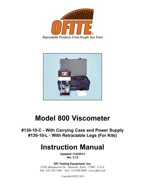
<strong>Model</strong> <strong>800</strong> <strong>Viscometer</strong><br />
#130-10-C - With Carrying Case and Power Supply<br />
#130-10-L - With Retractable Legs (For Kits)<br />
Instruction Manual<br />
Updated 11/4/2013<br />
Ver. 2.13<br />
<strong>OFI</strong> <strong>Testing</strong> <strong>Equipment</strong>, <strong>Inc</strong>.<br />
11302 Steeplecrest Dr. · Houston, Texas · 77065 · U.S.A.<br />
Tele: 832.320.7300 · Fax: 713.880.9886 · www.ofite.com<br />
©<br />
Copyright <strong>OFI</strong>TE 2013
Table of<br />
Contents<br />
Introduction ......................................................................................2<br />
Description .......................................................................................2<br />
Components......................................................................................3<br />
Specifications ...................................................................................5<br />
Safety.................................................................................................8<br />
Setup................................................................................................11<br />
Calibration.......................................................................................12<br />
Operation ........................................................................................15<br />
Calculations ....................................................................................17<br />
Disassembly ...................................................................................17<br />
Maintenance....................................................................................18<br />
<strong>OFI</strong>TE, 11302 Steeplecrest Dr., Houston, TX 77065 USA / Tel: 832-320-7300 / Fax: 713-880-9886 / www.ofite.com 1
Introduction<br />
Description<br />
The <strong>Model</strong> <strong>800</strong> 8-Speed Electronic <strong>Viscometer</strong> is designed and exclusively<br />
manufactured by <strong>OFI</strong> <strong>Testing</strong> <strong>Equipment</strong>, <strong>Inc</strong>. It is extensively used worldwide<br />
in both the field and laboratory for the precise measurement of rheological<br />
properties of fluids.<br />
The <strong>OFI</strong>TE <strong>Model</strong> <strong>800</strong> <strong>Viscometer</strong> determines the flow characteristics of oils<br />
and drilling fluids in terms of shear rate and shear stress over various time<br />
and temperature ranges at atmospheric pressure. Speeds are easily<br />
changed with a control knob, and shear stress values are displayed on a<br />
lighted magnified dial for ease of reading.<br />
The viscometer’s motor RPM is continuously monitored and automatically<br />
adjusted by the <strong>OFI</strong>TE Pulse-Power electronic speed regulator to maintain a<br />
constant shear rate under varying input power and drilling fluid shear conditions.<br />
The eight precisely regulated test speeds (shear rates in RPM) are as<br />
follows: 3 (Gel), 6, 30, 60, 100, 200, 300, and 600. A higher stirring speed is<br />
also provided. Speeds may be changed with a control knob selection, without<br />
stopping the motor.<br />
The <strong>Model</strong> <strong>800</strong> is suitable for both field and laboratory use and uses a motordriven<br />
electronic package to provide drilling fluid engineers with an extremely<br />
accurate and versatile tool. The <strong>Model</strong> <strong>800</strong> operates from a 13 - 16 VDC<br />
power source. The electronic regulator continuously monitors and automatically<br />
adjusts the rotational speed to maintain a constant shear rate under<br />
varying fluid shear conditions and input power variations that are commonly<br />
found on-site.<br />
<strong>OFI</strong>TE, 11302 Steeplecrest Dr., Houston, TX 77065 USA / Tel: 832-320-7300 / Fax: 713-880-9886 / www.ofite.com 2
Components<br />
#130-10 <strong>Model</strong> <strong>800</strong> 8-Speed <strong>Viscometer</strong><br />
#130-10-2 Speed Reference PC Board<br />
#130-10-3 Speed Control PC Board<br />
#130-10-4 Encoder Pick-up PC Board<br />
#130-10-5 Switch Plate<br />
#130-10-6 Wiring Harness<br />
#130-10-8 Encoder Disc<br />
#130-10-14 Motor<br />
#130-10-16 Belt<br />
#130-10-17 Cover<br />
#130-10-18 Lens for Cover<br />
#130-10-22 Card Guide for PC Boards<br />
#130-10-61 Light Assembly<br />
#130-21 Cup, Stainless Steel<br />
#132-50 Rotor<br />
#132-56 Sleeve<br />
#132-57 Shield<br />
#132-58 Bob<br />
#132-59 Bearing Retainer<br />
#132-71 Bearing<br />
#132-74 Locking Ring, 1.653"<br />
#132-75 Locking Ring, 1 ⁄2"<br />
#132-76 Locking Ring, 25 ⁄32"<br />
#134-05 Shielded Bearing for Bob Shaft<br />
#134-10 Torsion Spring Assy, F1<br />
#134-39 Clamp Sleeve for Torsion Spring<br />
#134-40 Shim, 5 ⁄8" × 3 ⁄8"<br />
#135-02 External Retainer Ring<br />
#135-18 Socket Set Screw<br />
#142-63 Locking Screw<br />
#163-26 Small Clip<br />
#170-21 Stand Support Rod<br />
#170-44 Rubber Foot, 1 ⁄2"<br />
#171-32 Midget Knob<br />
Case:<br />
#130-10-13 Carrying Case<br />
#130-13-13-1 Custom Foam Insert<br />
<strong>OFI</strong>TE, 11302 Steeplecrest Dr., Houston, TX 77065 USA / Tel: 832-320-7300 / Fax: 713-880-9886 / www.ofite.com 3
Optional:<br />
#132-56-C<br />
R1 Closed-Cup Rotor; 316 Stainless Steel (For completion and<br />
fracturing fluid testing.)<br />
#130-45-1 Calibration Instrument<br />
#132-58-7 Bob, B1, Threaded, Hollow, 303 Stainless Steel<br />
(Recommended for use with F0.2 spring)<br />
#132-80 Calibration Fluid, Certified, 100 cP, 16 oz<br />
Additional Bobs, Sleeves, and Springs:<br />
#132-58-1 B2 Bob, 303 Stainless Steel<br />
#132-58-2 B3 Bob, 303 Stainless Steel<br />
#132-58-3 B4 Bob, 303 Stainless Steel<br />
#132-58-4 B5 Bob, 303 Stainless Steel<br />
#132-58H B1 Bob, Hastelloy ®<br />
#132-56H R1 Sleeve, Hastelloy ®<br />
#134-10-2 F0.2 Torsion Spring Assembly (Green)<br />
#134-10-3 F0.5 Torsion Spring Assembly (Yellow)<br />
#134-10-4 F2.0 Torsion Spring Assembly (Red)<br />
#134-10-5 F3.0 Torsion Spring Assembly (Purple)<br />
#134-10-6 F4.0 Torsion Spring Assembly (White)<br />
#130-10-SP One Year Spare Parts<br />
#130-10-18 Lens for Cover<br />
#130-10-503 Fuse, 4 Amp, Qty: 4<br />
#130-10-61 Light Assembly<br />
#130-48 Retaining Ring Pliers, Internal<br />
#130-76-47 Retaining Ring Pliers, External<br />
#132-59 Bearing Retainer<br />
#132-71 Bearing, Qty: 2<br />
#132-75 Locking Ring, ½"<br />
#132-80 Calibration Fluid, 100 cP, 16 oz<br />
#132-81 Calibration Fluid, 50 cP, 16 oz<br />
#134-05-2 Shielded Bearing for Bob Shaft, Qty: 4<br />
#134-10 Torsion Spring Assy, F1<br />
#135-02 External Retainer Ring, Qty: 2<br />
<strong>OFI</strong>TE, 11302 Steeplecrest Dr., Houston, TX 77065 USA / Tel: 832-320-7300 / Fax: 713-880-9886 / www.ofite.com 4
Specifications<br />
Instrument Geometry True Couette Coaxial Cylinder<br />
Speed Accuracy (RPM) .1<br />
Motor Speeds (RPM)<br />
8 Fixed Speeds (600, 300, 200, 100, 60,<br />
30, 6, and 3)<br />
Readout<br />
Direct Dial<br />
Power Requirements 13 - 16 VDC<br />
Weight (kg) 6.0<br />
Dimensions (cm) 15.2 × 17.8 × 40.6<br />
Shipping Weight (kg) 20.4<br />
Shipping Dimensions (cm) 55.9 × 25.4 × 40.6<br />
Range of Measurement for <strong>Model</strong> <strong>800</strong><br />
Rotor - Bob R1B1 R1B2 R1B3 R1B4<br />
Rotor Radius, RR, (cm) 1.8415 1.8415 1.8415 1.8415<br />
Bob Radius, RB, (cm) 1.7245 1.2276 0.8622 0.8622<br />
Bob Height, L, (cm) 3.8 3.8 3.8 1.9<br />
Shear Gap, (cm) 0.117 0.6139 0.9793 0.9793<br />
R Ratio, RB/RR 0.9365 0.666 0.468 0.468<br />
Max. Shear Stress, SS MAX<br />
,<br />
(Dyne / cm 2 )<br />
R1B1 R1B2 R1B3 R1B4<br />
F 0.2 (Green) 330 651 1320 2644<br />
F 0.5 (Yellow) 840 1657 3359 6730<br />
F 1.0 (Blue) 1680 3314 6717 13460<br />
F 2.0 (Red) 3360 6629 13435 26921<br />
F 3.0 (Purple) 5040 9943 20152 40381<br />
F 4.0 (White) 6720 13257 26870 53841<br />
F 5.0 (Black) 8400 16571 33587 67302<br />
F 10.0 (Orange) 16<strong>800</strong> 33143 67175 134603<br />
<strong>OFI</strong>TE, 11302 Steeplecrest Dr., Houston, TX 77065 USA / Tel: 832-320-7300 / Fax: 713-880-9886 / www.ofite.com 5
Shear Rate Range R1B1 R1B2 R1B3 R1B4<br />
Shear Rate Constant, K R<br />
,<br />
(sec -1 per RPM)<br />
1.7023 0.3770 0.2682 0.2682<br />
Shear Rate, (sec -1 or 1/s)<br />
3 RPM<br />
5.11 1.13 0.80 0.80<br />
6 RPM 10.21 2.26 1.61 1.61<br />
30 RPM 51.07 11.31 8.05 8.05<br />
60 RPM 102.14 22.62 16.09 16.09<br />
100 RPM 170.23 37.70 26.82 26.82<br />
200 RPM 340.46 75.40 53.64 53.64<br />
300 RPM 510.69 113.10 80.46 80.46<br />
600 RPM 1021.38 226.20 160.92 160.92<br />
Viscosity Ranges <br />
(cP)<br />
Minimum Viscosity <br />
@600 RPM<br />
Maximum Viscosity <br />
@0.01 RPM<br />
R1B1 R1B2 R1B3 R1B4<br />
0.5 4.5 12.7 25<br />
10,000,000 89,000,000 255,000,000 500,000,000<br />
Computed for standard Torsion Spring (F 1.0). For other torsion springs, multiply by F factor<br />
Lower viscosities can be measured by the <strong>Model</strong> 900, however one must take into account the<br />
effect of bearing drag, Taylor vortices, zero offset, etc. when looking at the expected accuracy of<br />
the reading<br />
For practical purposes the minimum viscosity is limited to 0.5 cP due to Taylor Vortices<br />
Maximum viscosity is based on Maximum Shear Stress and Minimum shear rate (RPM). However,<br />
due to practical and physical limitations, it may be difficult to take these measurements.<br />
Viscosity Conversions<br />
To convert from units on left side to units on top, multiply by factor @ intercept.<br />
Centipoise<br />
(cP)<br />
Poise (P) g/(cm*s) (mN*s)m 2 mPa*s<br />
(lb*s)<br />
100 ft 2<br />
Centipoise<br />
(cP)<br />
1 0.01 0.01 1 1 0.002088<br />
Poise (P) 100 1 1 100 100 0.2088<br />
g/(cm*s) 100 1 1 100 100 0.2088<br />
(mN*s)m 2 1 0.01 0.01 1 1 0.002088<br />
mPa*s 1 0.01 0.01 1 1 0.002088<br />
(lb*s)<br />
100 ft 2 478.93 4.789 4.789 478.93 478.93 1<br />
<strong>OFI</strong>TE, 11302 Steeplecrest Dr., Houston, TX 77065 USA / Tel: 832-320-7300 / Fax: 713-880-9886 / www.ofite.com 6
Shear Stress Conversions<br />
To convert from units on left side to units on top, multiply by factor @ intercept.<br />
Dyne/cm 2 Pa lb/100ft 2 lb/ft 2 DR<br />
Dyne/cm 2 1 0.1 0.2084 0.002084 0.1957<br />
Pa 10 1 2.084 0.02084 1.957<br />
lb/100ft 2 4.788 0.4788 1 0.01 0.939<br />
lb/ft 2 478.8 47.88 100 1 93.9<br />
DR 5.107 0.5107 1.065 0.01065 1<br />
What Bob & Spring Should I Use?<br />
There is often confusion or misunderstanding about what a viscometer can<br />
actually measure. For example, a viscometer with an R1B1 F1 combination<br />
can measure water fairly well at 100 RPM and higher, but at 3 RPM,<br />
the readings would be shaky at best. While on the other hand, a linear fluid<br />
with a viscosity of 15000, could not get past 6 RPM with the same combination.<br />
To estimate which spring might be best, use the formula below to calculate<br />
a Minimum Spring factor, where one establishes the maximum RPM the<br />
fluid is going to be tested at, as well as what the expected “Apparent<br />
Viscosity” of the fluid at that RPM. If the Factor comes out as .87, then an<br />
F 1.0 spring should be used. If it comes out as .16, then an F 0.2 spring<br />
would be best. To cover all ranges, it may be necessary to use more than<br />
one spring.<br />
Minimum Spring Factor (F) =<br />
RPM(max) * AV(max)<br />
BOB(F)*90000<br />
Bob (F)<br />
R1B1 1<br />
R1B2 8.9<br />
R1B3 25.4<br />
R1B4 50.7<br />
<strong>OFI</strong>TE, 11302 Steeplecrest Dr., Houston, TX 77065 USA / Tel: 832-320-7300 / Fax: 713-880-9886 / www.ofite.com 7
Safety<br />
Explanation of Symbols<br />
Caution: Risk of Danger - This symbol directs the operator to consult<br />
the instruction manual for safety related warnings. (ISO-7000-0434)<br />
Whenever this symbol is used on the equipment, the user must<br />
consult the manual to determine the nature of the hazard and any<br />
actions which have to be taken.<br />
Fuse: This is the internationally recognized symbol for a user-replaceable<br />
fuse. This symbol will be followed by information required to guide<br />
the user to choose the proper replacement fuse.<br />
Direct Current (DC): This symbol indicates an input (or output) that is<br />
direct current only. (IEC 60417-5013)<br />
Note: This symbol will indicate important notes and helpful hints for the<br />
operation of the equipment.<br />
Polarity: This symbol indicates that the equipment receives positive<br />
voltage on the center pin of the connector and the return voltage is on<br />
the outer case.<br />
Tip: This symbol is used to identify operational information and best<br />
practices to obtain the most reliable data.<br />
Caution: Note - This symbol is used to indicate statements in the manual<br />
which warn against actions which may cause damage to the equipment<br />
during routine service or maintenance.<br />
<strong>OFI</strong>TE, 11302 Steeplecrest Dr., Houston, TX 77065 USA / Tel: 832-320-7300 / Fax: 713-880-9886 / www.ofite.com 8
Electrical Requirements<br />
The <strong>Model</strong> <strong>800</strong> <strong>Viscometer</strong> is to be powered by a DC power source capable<br />
of providing between 13 and 16 volts DC. The equipment is current<br />
limited to 4 amps by a user-replaceable fuse. However, we suggest that<br />
the power supply be current limited to less than 4 amps to provide additional<br />
protection to the equipment.<br />
Power (On/Off) Switch<br />
Input Connector:<br />
13 - 16 VDC Power<br />
Inlet / Emergency<br />
Disconnect Device<br />
When connecting the equipment to your power source, make sure that the<br />
13 - 16 VDC is connected to the center pin of the connector.<br />
The equipment is supplied with a user-replaceable fuse. This fuse must<br />
only be replaced by a 250-volt, 4-amp, time-delayed fuse.<br />
Environmental Conditions<br />
The equipment is designed for use in normal environmental conditions:<br />
- Indoors<br />
- At or below an altitude of 2,000 m (6,562 ft)<br />
- In temperatures between 5° and 40°C (41° - 104°F)<br />
- With a maximum relative humidity of 80% for temperatures up to 31°C<br />
(88°F) decreasing linearly to 50% relative humidity at 40°C (104°F)<br />
- This equipment has not been rated according to IEC 60529<br />
Note<br />
Installation<br />
The <strong>Model</strong> <strong>800</strong> <strong>Viscometer</strong> should be used in a location where it will not be<br />
subjected to excessive moisture. It should be placed on a flat, stable surface<br />
in a well-ventilated environment.<br />
<strong>OFI</strong>TE, 11302 Steeplecrest Dr., Houston, TX 77065 USA / Tel: 832-320-7300 / Fax: 713-880-9886 / www.ofite.com 9
Caution - Risk of Danger: This equipment produces sound pressure in<br />
excess of 85 dBA. Protective measures (such as hearing protection, noisereducing<br />
baffles, or a hood) should be considered.<br />
<strong>Equipment</strong> Operation<br />
Caution - Risk of Danger: The (13 - 16 VDC) power cord and the DC inlet<br />
are the emergency disconnect devices. Do not position the equipment<br />
such that it is difficult to operate the emergency disconnect devices.<br />
Caution - Risk of Danger: In normal operation, this equipment may liberate<br />
the potentially poisonous gasses listed below. However, the list below<br />
is dependent upon the chemical makeup of the sample fluids presented for<br />
testing. Care should be taken to ensure that: no unexpected or anomalous<br />
chemicals are contained or added to the test samples; the test environment<br />
is adequately ventilated; and, when necessary, appropriate personal protective<br />
equipment is employed.<br />
- Hydrogen Sulfide (H 2<br />
S)<br />
- Methane (CH 4<br />
)<br />
- Carbon Dioxide (CO 2<br />
)<br />
- Sulfur Dioxide (SO 2<br />
)<br />
Caution - Risk of Danger: The samples presented for testing may contain<br />
flammable substances. The following risk-reduction procedures must be followed<br />
to ensure the safe operation of the equipment.<br />
- Always use in a well-ventilated area.<br />
- Keep away from open flames.<br />
Caution - Risk of Danger: If this equipment is operated in a manner not<br />
specified by the manufacturer (<strong>OFI</strong>TE), the protections provided by the<br />
equipment may be impaired.<br />
Caution - Risk of Danger: This equipment may operate unexpectedly if the<br />
equipment is energized when the Speed Selector Knob and Power (On/Off)<br />
Switch are left in the “On” position. Care should be taken to ensure both<br />
switches are in the “Off” position prior to energizing the equipment. Also,<br />
care should be taken to ensure that the Speed Selector Knob is in the “Off”<br />
position prior to turning the Power (On/Off) Switch to the “On” position.<br />
Speed Selector Knob<br />
<strong>OFI</strong>TE, 11302 Steeplecrest Dr., Houston, TX 77065 USA / Tel: 832-320-7300 / Fax: 713-880-9886 / www.ofite.com 10
Setup<br />
1. Connect the instrument to a 13 - 16 VDC, current-limited power source.<br />
2. With the instrument turned off, place the splash guard onto the bob<br />
shaft with the short tube end pointed up towards the bearings. Push up.<br />
3. Screw on the appropriate bob with the tapered end up towards the<br />
splash guard.<br />
4. Place the sleeve onto the rotor over the bob. The threads assure the<br />
rotor will attach evenly and uniformly each and every time.<br />
5. The power switch is located on the back panel. Turn the unit on.<br />
6. Place a properly prepared sample of test fluid in a sample cup and<br />
immerse the rotor sleeve exactly to the fill line on the sleeve by raising<br />
the platform. Tighten the lock nut on the platform.<br />
Rotor<br />
Splash Guard<br />
Bob<br />
Sleeve<br />
Platform<br />
<strong>OFI</strong>TE, 11302 Steeplecrest Dr., Houston, TX 77065 USA / Tel: 832-320-7300 / Fax: 713-880-9886 / www.ofite.com 11
Calibration<br />
The <strong>Model</strong> <strong>800</strong> viscometer can lose calibration while in service if the bob<br />
shaft bearings become contaminated or if the bob shaft itself is bent. If the<br />
dial does not read zero when it should or if there is excessive dial deflection<br />
when the main shaft is turning, this may indicate that the bob shaft<br />
bearings are sticking. If the spring appears to be non-linear, the bob shaft<br />
may be bent. Your viscometer will require servicing if it exhibits any of<br />
these symptoms.<br />
According to API Recommended Practice 10B-2, viscometers being used<br />
for testing well cement should be calibrated quarterly. API Recommended<br />
Practice 13B-1 and 13B-2 specify viscometers being used for drilling fluids<br />
should be checked monthly.<br />
The <strong>OFI</strong>TE Calibrating Instrument (Part No. 130-45-1) and the Calibration<br />
Check Kit (Part No. 132-49) are available to facilitate calibration. The<br />
Calibrating Instrument uses a dead-weight method of calibrating, while the<br />
Calibration Check Kit is fluid based. Both are provided in the <strong>Model</strong> <strong>800</strong><br />
spare parts kit (Part No. 130-10-SP).<br />
130-45-1 Calibrating Instrument<br />
<strong>Equipment</strong>:<br />
#130-45-1 Calibrating Instrument for 8-Speed <strong>Viscometer</strong> (Requires a<br />
trained technician)<br />
#132-49 Calibration Check Kit<br />
Calibration Fluids, “Certified”:<br />
#132-84 Calibration Fluid, 20 CP, 16 oz (500 mL)<br />
#132-81 Calibration Fluid, 50 CP, 16 oz (500 mL)<br />
#132-80 Calibration Fluid, 100 CP, 16 oz (500 mL)<br />
#132-83 Calibration Fluid, 200 CP, 16 oz (500 mL)<br />
#132-82 Calibration Fluid, 500 CP, 16 oz (500 mL)<br />
132-49 Calibration Check Kit<br />
<strong>OFI</strong>TE, 11302 Steeplecrest Dr., Houston, TX 77065 USA / Tel: 832-320-7300 / Fax: 713-880-9886 / www.ofite.com 12
Procedure:<br />
1. Choose the certified calibration fluid using the temperature-viscosity<br />
chart supplied with the calibration fluid to cover the viscosity range of<br />
interest. Make sure the lot number on the chart matches the lot number<br />
on the fluid container. Each lot of standard fluid is individually certified.<br />
The viscosity will normally vary slightly from lot to lot.<br />
2. Clean and dry the viscometer bob, sleeve, and cup. Place the viscometer<br />
and the calibration fluid side-by-side on the counter top in a<br />
room with a reasonably constant temperature (variation of less than 5°F<br />
± 2.5°F). Allow the viscometer and the fluid to stand at least two hours<br />
to equilibrate.<br />
3. Operate the viscometer in air for two to four minutes to loosen up the<br />
bearings and gears. Observe the rotor sleeve for excessive wobbling<br />
and replace if necessary.<br />
4. Fill the cup to the scribed line with calibration fluid and place it on the<br />
viscometer stage. Move the stage upward until the fluid level is to the<br />
fill line on the sleeve.<br />
Never immerse the sleeve in fluids above the fill line.<br />
Fill Line<br />
<strong>Viscometer</strong> Sleeve<br />
5. Place a thermometer capable of ± 0.2°F (0.1°C) into the fluid and hold<br />
or tape it in place to prevent breakage. Operate the viscometer at a<br />
low speed setting until the thermometer reading becomes stable to<br />
within ± 0.2°F (0.1°C) per 30 seconds. Note and record the temperature<br />
reading.<br />
6. Once the temperature has stabilized, operate the viscometer at 600<br />
RPM and then at 300 RPM. Note and record the dial readings to the<br />
nearest 0.5 dial unit.<br />
<strong>OFI</strong>TE, 11302 Steeplecrest Dr., Houston, TX 77065 USA / Tel: 832-320-7300 / Fax: 713-880-9886 / www.ofite.com 13
7. Using the temperature-viscosity chart supplied with the calibration fluid,<br />
determine the certified viscosity to the nearest 0.5 centipoise.<br />
a. Compare the 300 RPM reading to standard viscosity and record the<br />
deviation plus or minus.<br />
b. Divide the 600 RPM dial reading by 1.98, compare that to standard<br />
viscosity, and record the deviation plus or minus.<br />
8. Deviations exceeding 1.5 dial units are not acceptable. If the deviation<br />
exceeds this tolerance, the viscometer will require adjustments or calibration<br />
by a qualified technician.<br />
9. Record the viscometer serial number, date, and deviation. Mark on the<br />
viscometer the date of calibration and a general indication of the calibration<br />
check status.<br />
<strong>OFI</strong>TE, 11302 Steeplecrest Dr., Houston, TX 77065 USA / Tel: 832-320-7300 / Fax: 713-880-9886 / www.ofite.com 14
Operation<br />
Measuring Viscosity:<br />
1. Mix the sample on the “STIR” setting for 10 seconds while heating or<br />
cooling the fluid. Monitor the temperature with a thermometer.<br />
Continue to mix until the sample reaches the target temperature.<br />
2. Rotate the knob to one of the speed settings. When the dial reading<br />
stabilizes, record the reading and the temperature. Repeat this step for<br />
any other speeds that your test requires.<br />
<br />
Tip<br />
Always start with the higher RPM and work your way down to the lowest<br />
RPM. For example, if you need readings at 100 RPM, 200 RPM,<br />
and 300 RPM, record the measurement at 300 RPM first, then 200<br />
RPM, then 100 RPM, then gel strengths (if necessary).<br />
Measuring Gel Strength:<br />
1. Mix the sample on the “STIR” setting for 10 seconds.<br />
2. Rotate the knob to “GEL” and immediately shut off the power.<br />
3. As soon as the sleeve stops rotating, wait 10 seconds and turn the<br />
power back on while looking at the dial. Record the maximum dial<br />
deflection before the gel breaks. This is the 10 second gel strength.<br />
Note<br />
When measuring gel properties, the dial does not have to return to zero<br />
during the quiescent period. Therefore, it should not be forced back to the<br />
zero setting if it does not freely do so. When determining the maximum<br />
dial deflection, no allowance needs to be made if the dial did not start at<br />
zero. Only the maximum dial deflection is of interest. Rheological properties<br />
and characteristics of the sample will determine if the dial returns to<br />
zero during the quiescent periods of the gel measurements.<br />
4. For the 10 minute gel strength, re-stir the fluid and wait 10 minutes<br />
before recording the maximum dial deflection.<br />
<strong>OFI</strong>TE, 11302 Steeplecrest Dr., Houston, TX 77065 USA / Tel: 832-320-7300 / Fax: 713-880-9886 / www.ofite.com 15
API <strong>Testing</strong><br />
1. Mix the sample on the “STIR” setting for 10 seconds.<br />
2. Set the speed to 600 RPM. Wait for the reading to stabilize and then<br />
record the dial reading and temperature.<br />
3. Set the speed to 300 RPM. Wait for the reading to stabilize and then<br />
record the dial reading and temperature.<br />
4. Stir the sample again for 10 seconds.<br />
5. Set the speed to “GEL” and immediately shut off the power.<br />
6. As soon as the sleeve stops rotating, wait 10 seconds and turn the<br />
power on while looking at the dial. Record the maximum dial deflection<br />
before the gel breaks. This is the 10 second gel strength.<br />
7. For the 10 minute gel strength, re-stir the fluid and wait 10 minutes<br />
before recording the maximum dial deflection.<br />
<strong>OFI</strong>TE, 11302 Steeplecrest Dr., Houston, TX 77065 USA / Tel: 832-320-7300 / Fax: 713-880-9886 / www.ofite.com 16
Calculations<br />
Plastic Viscosity (PV), cP<br />
Yield Point (YP), lb./100 ft 2<br />
= 600 RPM reading - 300 RPM reading<br />
= 300 RPM reading - Plastic Viscosity (PV)<br />
Apparent Viscosity (AV), cP = 600 RPM reading / 2<br />
Gel Strength, 10 second, lb/100 ft 2<br />
Gel Strength, 10 minute, lb/100 ft 2<br />
= the maximum dial deflection after 10 sec.<br />
= the maximum dial deflection after 10 min.<br />
Disassembly<br />
Clean the viscometer after every test.<br />
1. Remove the sleeve from the rotor.<br />
2. Remove the bob.<br />
3. Once the bob is removed, remove the splash guard and wipe down the<br />
bob shaft. Clean all removed parts with soap and water and dry them<br />
thoroughly.<br />
Keep the instrument upright at all times, especially when cleaning<br />
so that water does not get into the bearings.<br />
<strong>OFI</strong>TE, 11302 Steeplecrest Dr., Houston, TX 77065 USA / Tel: 832-320-7300 / Fax: 713-880-9886 / www.ofite.com 17
Maintenance<br />
From time to time, the bearings will need to be changed. Complete the following<br />
to determine if it is time to perform this maintenance procedure:<br />
1. The viscometer should have a zero dial reading when placed in an<br />
upright position with the sleeve not immersed in fluid prior to running<br />
tests.<br />
2. With the instrument in this position, rotate the sleeve at 600 RPM. The<br />
dial reading in air should not exceed one.<br />
3. Place water in a suitable container and immerse the rotor sleeve to the fill<br />
line.<br />
4. Rotate the sleeve at 600 RPM. The dial reading in water should be<br />
between 1.5 and 3.0.<br />
5. At 300 RPM, the dial reading in water should be between 0.5 and 2.0.<br />
If the viscometer fails to pass any one of the above tests, the bearings are<br />
bad and should be replaced by a qualified instrument technician.<br />
Bob Shaft Bearing and Torsion Spring Replacement:<br />
Tools Required:<br />
Allen Wrench, 1 ⁄16"<br />
Phillips Head Screwdriver<br />
Retainer Ring Pliers (small)<br />
External Retainer Ring Pliers<br />
Flat Screw Driver<br />
Bob Shaft Wrench<br />
Replacement Parts:<br />
#134-05-2 Bearing for Bob Shaft, Shielded<br />
!<br />
Important<br />
1. Unplug the power supply and remove the sleeve and bob.<br />
Use the bob shaft wrench to hold the shaft in place while unscrewing the<br />
bob.<br />
2. With the flat-head screw driver, loosen the set screw in the speed control<br />
knob. Remove the speed control knob from the unit.<br />
3. Remove all four flat-head screws on the outer housing cover and gently<br />
lift the cover upward.<br />
4. Loosen the set screw at the top of the Zero Calibration Knob one turn<br />
counterclockwise.<br />
<strong>OFI</strong>TE, 11302 Steeplecrest Dr., Houston, TX 77065 USA / Tel: 832-320-7300 / Fax: 713-880-9886 / www.ofite.com 18
5. Loosen the two screws in the top of the Index Block. Pull the Index<br />
Block straight back to prevent damage to the dial or stop pin.<br />
6. Loosen the top set screw on the dial one turn counterclockwise.<br />
7. Gently lift the torsion spring straight up.<br />
Do not stretch the torsion spring.<br />
If you are replacing only the torsion spring, discard the old spring, and<br />
skip to step 21 to complete the process.<br />
Set Screw (Step 4)<br />
Bridge<br />
Dial<br />
Bearing Mount<br />
Torsion Spring<br />
Zero Calibration Knob<br />
Set Screw (Step 6)<br />
Index Block<br />
8. Remove the four screws from the bridge, unclip the light, and lay the<br />
bridge gently to the side.<br />
Do not touch the encoder that encircles the flywheel.<br />
9. While holding the bob shaft with the bob shaft wrench, loosen the set<br />
screw (one turn counterclockwise) on the bottom of the dial. Remove<br />
the bob shaft by pulling it straight down.<br />
<strong>OFI</strong>TE, 11302 Steeplecrest Dr., Houston, TX 77065 USA / Tel: 832-320-7300 / Fax: 713-880-9886 / www.ofite.com 19
10. Remove the two screws on the bearing mount and pull it straight up to<br />
remove it.<br />
Be careful not to damage the pins.<br />
Set Screw<br />
Retainer Clip<br />
Set Screw<br />
Upper Bearing<br />
Bearing Mount<br />
11. The upper bearing is located inside the bearing mount. Use retaining<br />
ring pliers to remove the retainer ring. Push the bearing upwards to<br />
remove it from the bearing mount.<br />
12. Use surgical gloves to insert a new upper bearing into the bearing mount.<br />
Gently push downward to seat the bearing. Replace the retainer ring<br />
with the retaining ring pliers.<br />
Do not touch the bearing with bare hands. Dirt, oils, and other contaminants<br />
can damage the bearing.<br />
13. Slide the bearing mount back onto the two pins and tighten the two<br />
screws.<br />
14. Remove the Splash Guard by sliding it straight down the shaft.<br />
15. Loosen the set screw on the bearing shield (one turn counterclockwise).<br />
Slide the bearing and bearing shield off the bob shaft.<br />
16. Use surgical gloves to slide a new lower bearing onto the bob shaft.<br />
<strong>OFI</strong>TE, 11302 Steeplecrest Dr., Houston, TX 77065 USA / Tel: 832-320-7300 / Fax: 713-880-9886 / www.ofite.com 20
17. Slide the bearing shield back onto the bob shaft and tighten the set<br />
screw. Slide the splash guard onto the bob shaft until in touches the<br />
bearing shield.<br />
Note<br />
The bearing should be able to free spin for up to two minutes. If it<br />
does not, replace it with a new bearing.<br />
Torsion Spring<br />
Brass Bearing Mount<br />
Bob Shaft<br />
Lower Bearing<br />
Bearing Shield<br />
Splash Guard<br />
18. Slide the bob shaft up through the bearing mount. Turn the bob shaft until<br />
the flat portion is facing the front of the unit.<br />
19. Align the bottom set screw on the dial with the flat portion of the bob<br />
shaft and tighten firmly. Make sure the set screws are perpendicular to<br />
the top of the bob shaft.<br />
Note<br />
The bob shaft should rotate smoothly without any noise.<br />
20. Replace the bridge being careful not to touch or bend the encoder.<br />
Tighten the four screws. Re-attach the light.<br />
21. Gently slide the torsion spring through the Zero Calibration Knob and into<br />
the dial. Make sure the bottom of the torsion spring is seated properly<br />
inside the dial. Tighten the set screw at the top of the dial to secure the<br />
torsion spring.<br />
22. Slide the index block into place. Tighten the two screws. Make sure the<br />
zero mark on the dial is aligned with the mark on the index block.<br />
<strong>OFI</strong>TE, 11302 Steeplecrest Dr., Houston, TX 77065 USA / Tel: 832-320-7300 / Fax: 713-880-9886 / www.ofite.com 21
23. Press down on the torsion spring until the internal ring is flush with the<br />
Zero Knob and tighten the set screw.<br />
24. Loosen the set screw on the bridge on turn counterclockwise. Adjust<br />
the Zero Calibration Knob so that the zero on the dial lines up with the<br />
line on the index block. Tighten the set screw.<br />
25. Replace the bob and sleeve.<br />
26. Re-attach the main housing cover.<br />
27. Re-attached the speed control knob.<br />
28. Re-calibrate the instrument.<br />
<strong>OFI</strong>TE, 11302 Steeplecrest Dr., Houston, TX 77065 USA / Tel: 832-320-7300 / Fax: 713-880-9886 / www.ofite.com 22