120-52 - Dual-Cell Ultrasonic Cement Analyzer - Instruction Manual
120-52 - Dual-Cell Ultrasonic Cement Analyzer - Instruction Manual
120-52 - Dual-Cell Ultrasonic Cement Analyzer - Instruction Manual
You also want an ePaper? Increase the reach of your titles
YUMPU automatically turns print PDFs into web optimized ePapers that Google loves.
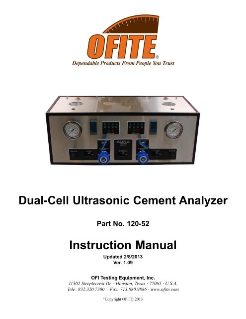
<strong>Dual</strong>-<strong>Cell</strong> <strong>Ultrasonic</strong> <strong>Cement</strong> <strong>Analyzer</strong><br />
Part No. <strong>120</strong>-<strong>52</strong><br />
<strong>Instruction</strong> <strong>Manual</strong><br />
Updated 2/8/2013<br />
Ver. 1.09<br />
OFI Testing Equipment, Inc.<br />
11302 Steeplecrest Dr. · Houston, Texas · 77065 · U.S.A.<br />
Tele: 832.320.7300 · Fax: 713.880.9886 · www.ofite.com<br />
©<br />
Copyright OFITE 2013
Table of<br />
Contents<br />
Intro.......................................................................................................2<br />
Description...........................................................................................2<br />
Features................................................................................................2<br />
Specifications ......................................................................................3<br />
Components.........................................................................................3<br />
Setup.....................................................................................................4<br />
UCA..................................................................................................4<br />
Software ...........................................................................................4<br />
Temperature Profile..........................................................................6<br />
Operation..............................................................................................7<br />
Temperature Controller ...................................................................7<br />
Alarms ............................................................................................10<br />
Preparing the Test <strong>Cell</strong> ..................................................................10<br />
Performing the Test........................................................................13<br />
Removing the Test <strong>Cell</strong>..................................................................17<br />
Maintenance.......................................................................................18<br />
Cleaning the Test <strong>Cell</strong>....................................................................18<br />
General ..........................................................................................20<br />
Calibration ......................................................................................21<br />
Multiple Instruments.......................................................................22<br />
Grounding ......................................................................................23<br />
Appendix ............................................................................................24<br />
Diagram..........................................................................................24<br />
OFITE, 11302 Steeplecrest Dr., Houston, TX 77065 USA / Tel: 832-320-7300 / Fax: 713-880-9886 / www.ofite.com 1
Intro<br />
By measuring the change in velocity of an acoustic signal, the <strong>Ultrasonic</strong><br />
<strong>Cement</strong> <strong>Analyzer</strong> provides a continuous non-destructive method of determining<br />
compressive strength as a function of time.<br />
Description<br />
The cement slurry to be tested is placed in an autoclave unit with temperature<br />
and pressure adjusted to simulate downhole conditions. An acoustic<br />
signal is then transmitted through the cement sample. As the strength of<br />
the cement increases over time, the acoustic signal travels faster through<br />
the sample.<br />
A computer running customized Windows ® software measures the transit<br />
times of the signal over time and interpolates the compressive strength values.<br />
This data is available in real time onscreen and is also stored in an<br />
Excel ® spreadsheet for easy graphical viewing and printing.<br />
The dual-cell UCA consists of two single-cell UCA units in a single enclosure.<br />
Both units share electrical power; air, water, and drain plumbing; and<br />
PC to UCA connectivity. All other systems (heating, pressurization, etc.)<br />
are completely separate.<br />
Features<br />
- <strong>Cement</strong> samples are not destroyed<br />
- Additional autoclaves are available<br />
- Programmable temperature control (up to 400°F or 204.4°C)<br />
- Regulator and back pressure regulator provide extensive pressure control<br />
(up to 16,000 PSI or 110,400 kPa)<br />
- Data is available instantly onscreen and is automatically converted to<br />
Excel ® spreadsheet format<br />
OFITE, 11302 Steeplecrest Dr., Houston, TX 77065 USA / Tel: 832-320-7300 / Fax: 713-880-9886 / www.ofite.com 2
Specifications<br />
Components<br />
- Size: 15" × 40" × 18" (38 × 122 × 45.8 cm)<br />
- Weight: 170 lbs (78 kg)<br />
- Air Supply - 100 PSI (690 kPa) Recommended; 150 PSI (1,035 kPa)<br />
Maximum; ¼" NPT Connector<br />
- Water Supply - standard tap water; ¼" NPT Connector<br />
- <strong>120</strong>V/220 V, 50/60 Hz Power<br />
- Computer: Windows XP or higher, RS-232 Serial Port (or Serial to USB<br />
Adapter), Minimum Screen Resolution: 1280 × 720<br />
Packing List:<br />
#<strong>120</strong>-00-001 Sonalert; Qty: 2<br />
#<strong>120</strong>-25-059 Contactor; Qty: 2<br />
#<strong>120</strong>-50-TR Transducer; Set of 2; Qty: 2<br />
#<strong>120</strong>-50-001 Circuit Board<br />
#<strong>120</strong>-51-001 Temperature Controller, Eurotherm Model 2408 P4; Qty: 2<br />
#<strong>120</strong>-104 Rupture Disk; 17,500 PSI (121 MPa); Qty: 2<br />
#<strong>120</strong>-910-061 Union Elbow; 1 ⁄4" Tube; Qty: 4<br />
#123-011 O-ring for Test <strong>Cell</strong>; Qty: 4<br />
#123-023 Low-Temperature Acoustic Couplant; 250°F (121.1°C)<br />
#123-024 High-Temperature Acoustic Couplant; 600°F (315.5°C)<br />
#130-75-71 17" Monitor<br />
#130-75-74 Desktop Computer<br />
#130-76-11 Terminal; Qty: 14<br />
#130-77-025 Leveling Leg; Qty: 4<br />
#130-77-054 1 ⁄8" Male Elbow; Qty: 6<br />
#130-78-045 Male Connector; 1 ⁄4" Tube OD × 1 ⁄4"; Qty: 7<br />
#130-78-046 Stainless Steel Swagelok Tube Fitting; Male Connector; 1 ⁄4"<br />
Tube OD × 3 ⁄8" Male NPT; Qty: 2<br />
#130-79-14 Printer<br />
#130-79-14-1 USB 2.0 Cable; A/B; 10'<br />
#130-79-15 Serial Cable; OB9; M/F<br />
#130-79-26 3-Pin Female Connector; Qty: 4<br />
#130-79-27 3-Pin Male Connector; Qty: 4<br />
#150-80-074 Quick-Connect Stem<br />
#1<strong>52</strong>-38 AC Power Cord; 3-Conductor; International (Continental<br />
European); Qty: 3<br />
#171-48-3 Plug Receptacle; Qty: 2<br />
#172-24 Solid State Relay; 240V-25A<br />
Optional:<br />
#<strong>120</strong>-<strong>52</strong>-SP Spare Parts for #<strong>120</strong>-<strong>52</strong>:<br />
#122-004 Thermocouple Assembly; Qty: 2<br />
#122-010 Heater Assembly; Qty: 2<br />
#122-053 Rupture Disk 22,500 PSI (155 MPa); Qty: 4<br />
#122-073 2-Amp Fuse; 5 mm × 20 mm; Qty: 8<br />
#122-077 10-Amp Fuse; 5 mm × 20 mm; Qty: 8<br />
#123-011 Test <strong>Cell</strong> O-ring; Qty: 160<br />
#123-023 Low-Temperature Acoustic Couplant; 250°F (121.1°C); Qty: 6<br />
#123-024 High-Temperature Acoustic Couplant; 600°F (315.5°C); Qty: 4<br />
OFITE, 11302 Steeplecrest Dr., Houston, TX 77065 USA / Tel: 832-320-7300 / Fax: 713-880-9886 / www.ofite.com 3
Setup<br />
UCA<br />
1. Begin by making sure all switches are off and all pressure knobs are<br />
turned completely counter-clockwise.<br />
2. Connect the AIR, WATER, and DRAIN connectors on the back of the<br />
unit to their appropriate source and plug in the power cord to a grounded,<br />
230-volt power source.<br />
3. Turn the “Main” switch on.<br />
Setup<br />
Software<br />
Before you begin your test, you must prepare the PC to record the data.<br />
1. Connect the PC to the UCA with the serial cable (supplied) and turn the<br />
PC on.<br />
2. Open the “OFITE UCA” software by double-clicking the icon on the<br />
desktop.<br />
3. The software has a set of six tabs:<br />
- <strong>Cell</strong> Info - Shows the current test configuration and a graph of the<br />
temperature profile. One tab for each cell.<br />
- Dashboard - Shows graphs for both cells along with current test data.<br />
- <strong>Cell</strong> Chart - Shows a graph for one cell at a time. One tab for each cell.<br />
- Log Data - Shows the raw data for both cells.<br />
OFITE, 11302 Steeplecrest Dr., Houston, TX 77065 USA / Tel: 832-320-7300 / Fax: 713-880-9886 / www.ofite.com 4
4. From the “Utilities” menu, click “Setup”:<br />
“COM Port” - Select the COM port the PC is connected to.<br />
“Temp Unit” - Select °F or °C<br />
“Pressure” - Select PSI or MPa<br />
“UCA #” - Enter an ID number for the UCA unit. This number will print<br />
on the chart at the end of the test.<br />
“Archive Path” - Choose a location to save archive files<br />
“Logo Path” - Select a logo file (.jpg format) to print on the chart.<br />
“Strength @”, “Strength 2 @”, “Strength 3 @” - Enter a time in each<br />
of these fields. The software will record the compressive strength of<br />
the sample of each of these times and print it on the chart.<br />
“CS #1”, “CS #2”, “CS #3” - Enter a compressive strength value in each<br />
of these fields. When the cement reaches that compressive strength, the<br />
software will record the elapsed time and print it on the graph.<br />
“Print to Printer” - When this option is selected, a graph of the test results<br />
will automatically print to the default printer when a test is complete.<br />
5. Before starting a test, select “Load <strong>Cell</strong> Infos” from the “Utilities” menu.<br />
Enter the necessary information and click “OK”.<br />
This information is for reference only. It will print on the graph at the<br />
end of the test. It will not affect the test itself.<br />
OFITE, 11302 Steeplecrest Dr., Houston, TX 77065 USA / Tel: 832-320-7300 / Fax: 713-880-9886 / www.ofite.com 5
Setup<br />
Temperature Profile<br />
The UCA Software includes a Temperature Profile Builder. Here you can<br />
create a custom temperature profile for your test.<br />
If you prefer to build a temperature profile manually using the Eurotherm<br />
controls, select “MANUAL” from the “Temperature Profiles List” on the UCA<br />
information tab and refer to page 7 for instructions on programming the<br />
Eurotherm.<br />
1. Select “Temp Profile Builder” from the “Utilities” menu.<br />
2. Either select a test to edit from the list on the left-hand side of the<br />
screen, or click “New Test” to build a new test.<br />
3. Enter a test name.<br />
4. Click the “Add” button to add a step. As you add steps, the graph below<br />
will change to reflect the new profile. There are three Step Types:<br />
a. Hold - This will hold the current temperature for a set number of<br />
minutes. You will be prompted for the hold time.<br />
b. Ramp - This will increase the temperature up to the target in a set<br />
number of minutes. You will be prompted for the ramp time and target<br />
temperature.<br />
c. Step - This will increase the temperature up to the target as fast as<br />
possible. You will be prompted for the target temperature.<br />
5. Click the “OK” button to add the step.<br />
6. Make sure the “Hold Indefinitely” option is checked. With this option<br />
turned on, the test will run until you click the “End Test” button. If this<br />
option is not checked, the test will end when all the steps in the<br />
Temperature Profile are complete.<br />
7. Click the “OK” button to exit the Temperature Profile Builder. The new<br />
Temperature Profile will now appear in the “Temperature Profiles List”<br />
on the UCA information tab.<br />
OFITE, 11302 Steeplecrest Dr., Houston, TX 77065 USA / Tel: 832-320-7300 / Fax: 713-880-9886 / www.ofite.com 6
Operation<br />
Temperature Controller<br />
The Eurotherm temperature controller allows you to program a temperature<br />
profile for your test. This profile will be divided into at least two segments.<br />
Each segment represents either a change in temperature or a period of<br />
time to hold the current temperature.<br />
The four buttons along the bottom of the display provide access to the temperature<br />
controller settings. Begin by pressing the “PAGE” button three<br />
times. The display will read "Prog List". Now, press the “SCROLL” key<br />
repeatedly until the setting you wish to change is shown on the display. Then<br />
press either arrow key until the appropriate value is displayed. Once you've<br />
chosen a value, press the “SCROLL” key again to select a new setting.<br />
For more information, refer to the Eurotherm instruction manual.<br />
Temperature Controller<br />
RUN/HOLD<br />
Page<br />
Scroll<br />
The first group of settings should read as follows:<br />
!<br />
Important<br />
Setting Value<br />
Prg1 1<br />
Hb OFF<br />
Hb.u 0.0<br />
Rmp.u min<br />
Dwl.u min<br />
Cyc.n 1<br />
These settings will be the same for every test. Do not change them.<br />
OFITE, 11302 Steeplecrest Dr., Houston, TX 77065 USA / Tel: 832-320-7300 / Fax: 713-880-9886 / www.ofite.com 7
1. Begin by defining the first segment of the test.<br />
a. Press the “SCROLL” key repeatedly until “Seg” appears on the<br />
display.<br />
b. Press either arrow key repeatedly until “1” appears on the display.<br />
You are now editing segment 1.<br />
2. The first setting is “Type”.<br />
a. Press the “SCROLL” key until the word “Type” appears on the<br />
display.<br />
b. The available options are “rmp.r”, “rmp.t”, or “dwell”. Press either<br />
arrow key until the appropriate value appears on the display.<br />
Rmp.r programs the controller to steadily increase the temperature<br />
by a specified rate (degrees per minute). If you choose this value,<br />
your next option will be “Tgt”, which is your target temperature and<br />
then “Rate” which is the rate you want the temperature to increase.<br />
Rmp.t increases the temperature over a specified time interval<br />
(minutes). If you choose this value, your next option will be “Tgt”<br />
(target temperature) and then “Dur” (duration in minutes).<br />
Dwell holds the temperature at its current setting for a specified<br />
length of time. If you choose this value, your next option will be<br />
“Dur” (duration in minutes).<br />
3. Now define the second segment.<br />
a. Press the “SCROLL” key until “Seg” appears on the display.<br />
b. Press either arrow key until “2” appears on the display. You are<br />
now editing segment 2.<br />
4. Continue this process with each segment in the test.<br />
5. When you reach the last segment, set the “Type” to “end”. The next<br />
setting will be “End.t”.<br />
If you choose “sop”, the heat will be turned off and the test ended.<br />
If you choose “dwell”, the heat will be held at the current temperature<br />
indefinitely.<br />
Example 1:<br />
Heat the sample at 2.5° per minute and stop at 150°. Hold at 150° for 180<br />
minutes and then stop the heat.<br />
OFITE, 11302 Steeplecrest Dr., Houston, TX 77065 USA / Tel: 832-320-7300 / Fax: 713-880-9886 / www.ofite.com 8
Setting Value Description<br />
Prg 1<br />
Hb OFF<br />
Hb.u 0.0<br />
Rmp.u min<br />
Dwl.u min<br />
Cyc.n 1<br />
Seg 1 Segment 1<br />
Type rmp.r Increase temperature at a specified rate<br />
Tgt 150 Heat to 150°<br />
Rate 2.5 Increase temperature at 2.5° per minute<br />
Seg 2 Segment 2<br />
Type dwell Hold on the current temperature<br />
Dur 180 Hold for 180 minutes<br />
Seg 3 Segment 3<br />
Type end This is the last segment<br />
End.t sop Stop the heat<br />
Example 2:<br />
Heat the sample to 200° over a period of 90 minutes. Then increase the<br />
temperature to 300° at a rate of 3° per minute. Hold that temperature until<br />
the unit is turned off.<br />
Prg 1<br />
Hb OFF<br />
Hb.u 0.0<br />
Rmp.u min<br />
Dwl.u min<br />
Cyc.n 1<br />
Seg 1 Segment 1<br />
Type rmp.t Increase temperature for a specified time<br />
Tgt 200 Heat to 200°<br />
Dur 90 Increase temperature for 90 minutes<br />
Seg 2 Segment 2<br />
Type rmp.r Increase temperature at a specified rate<br />
Tgt 300 Heat to 300°<br />
Rate 3 Increase temperature at 3° per minute<br />
Seg 3 Segment 3<br />
Type end This is the last segment<br />
End.t dwell Hold at the current temperature indefinitely<br />
OFITE, 11302 Steeplecrest Dr., Houston, TX 77065 USA / Tel: 832-320-7300 / Fax: 713-880-9886 / www.ofite.com 9
Operation<br />
Alarms<br />
The <strong>Ultrasonic</strong> <strong>Cement</strong> <strong>Analyzer</strong> is designed to protect itself from a heating<br />
malfunction. If the temperature of the unit reaches a critical level, the internal<br />
alarm automatically turns off the heat and the pump. Two switches on<br />
the front control panel determine how the operator is notified of an alarm.<br />
If the “Sonalert” switch is turned on, an audible alarm will sound. If the<br />
red “Alarm” switch is turned on, a light behind the switch will blink. These<br />
two alarms can be activated independent of each other.<br />
If both alarm switches are off, an alarm condition can still be triggered.<br />
However, there will be no warning to indicate the alarm. It is highly recommended<br />
that at least one alarm notification is turned on at all times.<br />
Operation<br />
Preparing the Test <strong>Cell</strong><br />
For a complete diagram of the test cell, refer to page 24.<br />
1. With both cell caps removed, examine the inside of the test cell from<br />
both ends. Below each set of threads is a small groove. The end with<br />
the smaller groove is the bottom of the test cell. Some cells have a<br />
label on the outside that indicates which end is the top.<br />
Groove<br />
2. Place a metal seal ring onto the bottom cell cap with an<br />
o-ring on top of it. The narrow side of the metal seal ring<br />
(see diagram of cross-section) should point away from<br />
the o-ring.<br />
3. Place an o-ring on the top cell cap between the metal<br />
seal ring and the retaining ring.<br />
Metal Seal Ring<br />
(Cross Section)<br />
Note<br />
You should not need to remove the retaining ring and metal seal ring<br />
from the top cell cap. However, if you do, be sure to place the metal<br />
seal ring back in the same orientation. The narrow end (see cross-section)<br />
should point toward the handles at the top of the test cell.<br />
OFITE, 11302 Steeplecrest Dr., Houston, TX 77065 USA / Tel: 832-320-7300 / Fax: 713-880-9886 / www.ofite.com 10
Wipe Off Excess Grease<br />
Retaining Ring<br />
O-ring<br />
Seal Ring<br />
Top <strong>Cell</strong> Cap<br />
Bottom <strong>Cell</strong> Cap<br />
<br />
Tip<br />
!<br />
Important<br />
4. Apply high-temperature grease to all internal surfaces of the test cell,<br />
including the threads. This will lubricate the threads and help prevent<br />
the cement from sticking to the sides of the cell.<br />
Leave only a thin layer of grease on the inside surfaces of the two cell<br />
caps. Excess grease will interfere with the transducer signal.<br />
5. Carefully screw the bottom cell cap onto the test cell and tighten it hand<br />
tight. The cell cap should turn smoothly in the test cell threads. If you<br />
encounter resistance, stop turning and unscrew the cap slightly. Then<br />
continue turning until the cap is completely tightened.<br />
6. Turn the test cell over and begin filling it with the cement slurry. Place<br />
the fill gauge against the inside of the test cell. Fill the cell until the<br />
cement barely touches the bottom of the measuring tool.<br />
It is important that you begin the test no more than 20 minutes<br />
after adding the cement slurry to the test cell.<br />
Fill Gauge (#<strong>120</strong>-50-018)<br />
OFITE, 11302 Steeplecrest Dr., Houston, TX 77065 USA / Tel: 832-320-7300 / Fax: 713-880-9886 / www.ofite.com 11
7. Carefully screw the top cell cap into the test cell, just as you did with<br />
the bottom cell cap.<br />
8. Make sure the transducers and the transducer holes in the cell caps<br />
are clean and free of debris. If they are not, they can be cleaned with a<br />
rag or paper towel. You can also use alcohol if further cleaning is necessary.<br />
Transducer<br />
Transducer Hole<br />
9. Apply a thin coat of an acoustic couplant to the two transducers.<br />
Note<br />
Two types of acoustic couplant are provided to you. The low-temperature<br />
gel should be used for temperatures up to 260°F (126.7°C). The<br />
high-temperature gel is suitable for higher temperatures. Carefully read<br />
the label before using either of these gels.<br />
OFITE, 11302 Steeplecrest Dr., Houston, TX 77065 USA / Tel: 832-320-7300 / Fax: 713-880-9886 / www.ofite.com 12
Operation<br />
Performing the Test<br />
1. Carefully place the cell into the heating jacket. Make sure the bottom<br />
transducer is inside the hole in the cell cap before lowering the cell.<br />
2. Connect the water/air pipe to the test cell.<br />
3. Attach the thermocouple to the test cell and hand tighten.<br />
4. Plug the transducer cable into the receptacle on the unit and place the<br />
transducer head into the hole in the cell cap. Place the spring holder<br />
over the transducer spring and secure it in place with the supplied screw.<br />
Water/Air Pipe<br />
Transducer Cable<br />
Test <strong>Cell</strong><br />
Spring Holder<br />
Thermocouple<br />
5. Make sure the pressure release valve is closed by turning it completely<br />
clockwise. Open both the Regulator and the Back Pressure Regulator<br />
by turning them completely counter-clockwise.<br />
6. Have a 5/8" wrench handy and open the water valve. When water<br />
starts coming out of the top cell cap, tighten the thermocouple. This will<br />
allow any air inside the test cell to escape before the test begins.<br />
Note<br />
You may hear water circulating through the system. This means the<br />
Back Pressure Regulator is open too much and pressure is venting<br />
from the cell. Close the Back Pressure Regulator slightly by turning it<br />
clockwise. The sound will stop and enough pressure will build in the<br />
cell to purge the air.<br />
7. Open the air valve and turn on the pump.<br />
OFITE, 11302 Steeplecrest Dr., Houston, TX 77065 USA / Tel: 832-320-7300 / Fax: 713-880-9886 / www.ofite.com 13
8. Turn the regulator clockwise to increase the pressure within the test<br />
cell. If the pressure does not build, turn the back pressure regulator<br />
clockwise. Allow the pressure to build slightly higher than necessary for<br />
your test. Then, turn the back pressure regulator counter-clockwise<br />
slowly to lower the pressure.<br />
The regulator allows pressure to enter the test cell. If the pressure falls<br />
too low, the regulator engages to bring it back up. Turning the regulator<br />
clockwise increases the amount of pressure allowed into the test cell.<br />
The back pressure regulator allows pressure to leave the test cell. If the<br />
pressure builds up too much (due to thermal expansion), the back pressure<br />
regulator bleeds off the excess. Turning the back pressure regulator<br />
counter-clockwise increases the amount of pressure allowed to<br />
leave the test cell.<br />
Correctly setting the regulator and back pressure regulator is a trial and<br />
error process. Always start with the back pressure regulator closed<br />
(clockwise) and use the regulator to increase the pressure higher than<br />
you need. Then, slowly open the back pressure regulator (counterclockwise)<br />
until the pressure drops to the desired level.<br />
Pressure<br />
Gauge<br />
Pressure<br />
Release<br />
Regulator<br />
Temperature<br />
Control Panel<br />
Air Supply<br />
Water Supply<br />
Back Pressure<br />
Regulator<br />
9. Once the cell is fully pressurized, it is time to start the test. In the software,<br />
select a “Temperature Profile” from the list. If you prefer to program<br />
the Eurotherm directly, select “MANUAL” from the list.<br />
OFITE, 11302 Steeplecrest Dr., Houston, TX 77065 USA / Tel: 832-320-7300 / Fax: 713-880-9886 / www.ofite.com 14
10. Click the “Start Test” button. Most of the fields on this screen do not<br />
affect the test. They only display on the graph at the end. However, it is<br />
important to give each test a unique Test Name.<br />
You can also access this screen from the Utilities menu by selecting<br />
“Load <strong>Cell</strong> Infos”. Here you can enter all the necessary information in<br />
advance, before preparing the cement sample.<br />
When you click the “OK” button, the test will begin.<br />
After 30 seconds, the software will begin graphing the data on the Chart<br />
and Dashboard tabs. The data fields above the graphs will begin to<br />
display readings immediately.<br />
“Test Time” - Time since the test began (HR:MIN)<br />
“Temperature” - Temperature within the test cell. (°F or °C, depending<br />
on the settings in the Options screen)<br />
“Transit Time” - Time required for the sound wave to travel through the<br />
sample (Milliseconds)<br />
“Compressive Strength” - Calculated compressive strength of the sample<br />
(PSI or MPa)<br />
“Acoustic Impedance” - Calculated acoustic impedance of the sample.<br />
Mostly used for well logging.<br />
OFITE, 11302 Steeplecrest Dr., Houston, TX 77065 USA / Tel: 832-320-7300 / Fax: 713-880-9886 / www.ofite.com 15
!<br />
Important<br />
Solid particles and air bubbles within the cement slurry can<br />
adversely affect the results of your test. The first Transit Time<br />
reading should be at least 10 µs. If it is less than 10 µs, wait a few<br />
minutes to see if the problem corrects itself. When you see a<br />
Transit Time greater than 10 µs, restart the test by clicking the<br />
“Stop Test” button and then clicking the “Start Test” button again.<br />
If the problem does not self-correct, you will need to remix your<br />
slurry and start the test again. To avoid this problem, carefully follow<br />
the mixing procedure in API Specification 10.<br />
11. Turn the “Heat” switch on.<br />
12. If you are running a manual temperature profile, push the “RUN/HOLD”<br />
button on the temperature controller to begin heating.<br />
OFITE, 11302 Steeplecrest Dr., Houston, TX 77065 USA / Tel: 832-320-7300 / Fax: 713-880-9886 / www.ofite.com 16
Operation<br />
Removing the Test <strong>Cell</strong><br />
1. When the test is complete, click the “End Test” button. The data file will<br />
be automatically saved in the folder specified on the “Setup” screen.<br />
2. If you were running a manual temperature profile, push the “Run/Hold”<br />
button on the controller and hold it until both lights are off.<br />
3. Turn the “Heat” switch off.<br />
4. Turn the “Cool” switch on and allow the test cell to cool completely.<br />
5. When the cell has cooled, turn the “Pump” and “Cool” switches off.<br />
6. Turn off both the water and air valves.<br />
7. Open the pressure release valve by slowly turning it counter-clockwise.<br />
8. Remove the water pipe, thermocouple, and transducer from the cell.<br />
9. Remove the test cell from the heating jacket.<br />
Use caution. The test cell contain a small amount of air at high<br />
temperature and / or pressure.<br />
OFITE, 11302 Steeplecrest Dr., Houston, TX 77065 USA / Tel: 832-320-7300 / Fax: 713-880-9886 / www.ofite.com 17
Maintenance<br />
Cleaning the Test <strong>Cell</strong><br />
The test cell must be cleaned immediately after every test. Any cement left<br />
in the test cell will harden and could damage the equipment. Clean all surfaces<br />
of the test cell with soap and water.<br />
Remove all o-rings, snap rings, and bushing and clean them individually.<br />
Carefully inspect them and discard any that show damage or wear.<br />
The cement in the UCA cell will be solid. It may be necessary to force the<br />
cement block out with pressure. Follow the procedure below:<br />
1. Remove both cell caps and pour off any excess water.<br />
Note<br />
<br />
Tip<br />
The cell caps will be too tight to remove by hand. To remove the cell<br />
caps, place the cell in a vise. Use the grooves on the body and cell<br />
caps to anchor it in the vise. Use the special wrench provided to<br />
loosen and remove each cell cap.<br />
If the test cell will not turn, remove it from the vise and hit the bottom<br />
cell cap with a mallet to loosen the cement inside. Then return the cell<br />
to the vise and try again.<br />
To remove top cap<br />
To remove bottom cap<br />
2. Screw the top cell cap back onto the top of the test cell.<br />
3. Screw the plug into one of the holes in the cell cap. The two holes are<br />
interchangeable.<br />
4. Attach the pressure hose to both the UCA unit and the test cell. Refer<br />
to the photos on the next page.<br />
OFITE, 11302 Steeplecrest Dr., Houston, TX 77065 USA / Tel: 832-320-7300 / Fax: 713-880-9886 / www.ofite.com 18
5. Plug the thermocouple into the unit. The unit will not function if the thermocouple<br />
is not plugged in.<br />
6. Turn on the pump.<br />
7. Very slowly increase the cell pressure.<br />
!<br />
Important<br />
8. When you hear the block of cement pop out of the test cell, release the<br />
cell pressure and turn off the pump.<br />
The cement block may be propelled out of the test cell with great<br />
force, causing serious injury and damage. Be sure to always<br />
point the test cell away from people or equipment.<br />
9. Disconnect the pressure hose.<br />
10. Remove the cell cap and thoroughly clean the test cell.<br />
¼" Plug<br />
Test <strong>Cell</strong> Adapter<br />
UCA Adapter<br />
OFITE, 11302 Steeplecrest Dr., Houston, TX 77065 USA / Tel: 832-320-7300 / Fax: 713-880-9886 / www.ofite.com 19
Maintenance<br />
General<br />
1. Before every test, inspect the o-rings, seal rings, and retaining ring for<br />
damage or wear. O-rings should not be cracked, split, or brittle. The<br />
seal rings and retaining ring should not be bent or dented. Replace<br />
any damaged pieces before beginning a new test.<br />
2. Ensure that the transducer holes in both cell caps are clean and free of<br />
debris. Also, be sure to clean the bottom surface of the transducers.<br />
This will help ensure a strong signal with minimal interference during a<br />
test.<br />
3. The UCA has five fuses inside the unit cabinet. To access them,<br />
remove the top panel.<br />
To replace a fuse, pull the fuse housing towards the front of the UCA.<br />
Then open the door on the side of the housing and remove the blown<br />
fuse. Place a new fuse into the housing, close the door, and push the<br />
housing back into place.<br />
The fuses are labeled F1 - F5. The amperage and function are listed<br />
below:<br />
F1: 10 Amp Main Power<br />
F2: 10 Amp Main Power<br />
F3: 2 Amp Fan<br />
F4: 6 Amp Heater<br />
F5: 2 Amp Pump and Cooling Solenoid<br />
OFITE, 11302 Steeplecrest Dr., Houston, TX 77065 USA / Tel: 832-320-7300 / Fax: 713-880-9886 / www.ofite.com 20
Appendix<br />
Calibration<br />
Your UCA unit has been calibrated at the factory, and should not need to<br />
be calibrated again. However, if any part of the test cell, transducers, control<br />
card, or software are changed, a calibration will be necessary.<br />
1. Begin by filling the test cell with distilled water and placing it in the unit<br />
as described in the “Preparing the Test <strong>Cell</strong>” section on page 10.<br />
2. Wait for the sample temperature to reach 70°F (21.1°C).<br />
3. Click the “Set Xmitter On” button.<br />
4. Select “Calibrate <strong>Cell</strong>” from the “Utilities” menu.<br />
5. The transit time should be about 17. If it is not, the unit will have to be<br />
serviced by an OFITE technician. If the transit time is close to 18, click<br />
“OK” to save the calibration and continue.<br />
6. Click the “Set Xmitter Off” button to turn off the transmitter.<br />
OFITE, 11302 Steeplecrest Dr., Houston, TX 77065 USA / Tel: 832-320-7300 / Fax: 713-880-9886 / www.ofite.com 21
Appendix<br />
Multiple Instruments<br />
It is possible to control multiple UCAs from a single computer. To setup the<br />
software for multiple UCAs, repeat the following procedure for each instrument.<br />
1. Plug each instrument into a separate serial port on the computer.<br />
2. On the computer, navigate to the “C:\Program Files (x86)” folder.<br />
3. Locate the “UCA” folder and select it.<br />
4. Hold down the CTRL key and then hit C. Then hold down the CTRL<br />
key and hit V. This will create a duplicate of the folder called “UCA -<br />
Copy”.<br />
5. Choose a name to identify the new instrument.<br />
6. Rename the new folder with the name of the instrument.<br />
<br />
Tip<br />
7. Locate the program file (.exe) inside the folder and rename it with the<br />
name of the instrument.<br />
For convenience, create a shortcut to this file on the desktop.<br />
8. Open the software using the new program file.<br />
9. Change the “Archive Path” to a new folder. See page 5 for instructions.<br />
Note<br />
Each instrument must have its own Archive Path.<br />
OFITE, 11302 Steeplecrest Dr., Houston, TX 77065 USA / Tel: 832-320-7300 / Fax: 713-880-9886 / www.ofite.com 22
Appendix<br />
Grounding<br />
Proper grounding protects the equipment operator from the risk of electric<br />
shock. The electrical cord provided with this equipment has an equipment<br />
grounding conductor and a grounding plug. Observe the following guidelines<br />
at all times:<br />
- Always connect the plug to a matching outlet that is properly installed<br />
and grounded.<br />
- If an extension cord is necessary, make sure it has three prongs and is<br />
compatible with the electrical cord provided with the equipment.<br />
- Do not modify the electrical cord provided with the equipment. If it is not<br />
compatible with any available outlets, have a compatible outlet installed<br />
by a qualified electrician.<br />
- If the equipment-grounding conductor (solid green or green and yellow)<br />
is improperly connected, the operator will be at risk of electrical shock.<br />
Never connect it to a live terminal.<br />
- Local codes may require a Ground Fault Interrupt Circuit (GFIC).<br />
- Repair or replace a damaged or worn cord immediately.<br />
- When in doubt, consult a qualified electrician.<br />
OFITE, 11302 Steeplecrest Dr., Houston, TX 77065 USA / Tel: 832-320-7300 / Fax: 713-880-9886 / www.ofite.com 23
Appendix<br />
Diagram<br />
Top Cap<br />
Seal Ring (#<strong>120</strong>-50-027)<br />
O-ring (#123-011)<br />
Retaining Ring<br />
(#<strong>120</strong>-50-026)<br />
<strong>Cell</strong> Body<br />
O-ring (#123-011)<br />
Seal Ring (#<strong>120</strong>-50-027)<br />
Base Cap<br />
OFITE, 11302 Steeplecrest Dr., Houston, TX 77065 USA / Tel: 832-320-7300 / Fax: 713-880-9886 / www.ofite.com 24


