298-00 - DADAFTA - Instruction Manual - OFI Testing Equipment, Inc.
298-00 - DADAFTA - Instruction Manual - OFI Testing Equipment, Inc.
298-00 - DADAFTA - Instruction Manual - OFI Testing Equipment, Inc.

You also want an ePaper? Increase the reach of your titles
YUMPU automatically turns print PDFs into web optimized ePapers that Google loves.
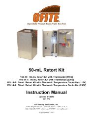
Diffused Air - Dissolved Air Flotation<br />
Test Apparatus (<strong>DADAFTA</strong>)<br />
Part No. <strong>298</strong>-<strong>00</strong><br />
<strong>Instruction</strong> <strong>Manual</strong><br />
Updated 1/2/2013<br />
Ver. 2.2<br />
<strong>OFI</strong> <strong>Testing</strong> <strong>Equipment</strong>, <strong>Inc</strong>.<br />
11302 Steeplecrest Dr. · Houston, Texas · 77065 · U.S.A.<br />
Tele: 832.320.73<strong>00</strong> · Fax: 713.880.9886 · www.ofite.com<br />
©<br />
Copyright <strong>OFI</strong>TE 2013
Table of<br />
Contents<br />
Intro.......................................................................................................2<br />
Components.........................................................................................2<br />
Specifications ......................................................................................4<br />
Required Reagents & Samples ..........................................................4<br />
Preparation...........................................................................................5<br />
Test Procedure.....................................................................................7<br />
Data Analysis .......................................................................................9<br />
Rise Rate .........................................................................................9<br />
Solids Content................................................................................10<br />
Interpreting Results ........................................................................11<br />
Alternate Procedure for Diffused Air...............................................12<br />
Formulas.............................................................................................14<br />
Total Solids.....................................................................................14<br />
Total Suspended Solids .................................................................15<br />
Air to Solids Ratio (A/S).................................................................17<br />
<strong>OFI</strong>TE, 11302 Steeplecrest Dr., Houston, TX 77065 USA / Tel: 832-320-73<strong>00</strong> / Fax: 713-880-9886 / www.ofite.com 1
Intro<br />
The performance of dissolved air flotation units can be enhanced by the addition<br />
of polymers. Polymers can increase solids recovery in the floated sludge<br />
from 85% to 99% and also reduce the suspended solids in the subnatant.<br />
Bench testing utilizing the Poly Prep “N” Floc and Diffused Air Dissolved Air<br />
Flotation Test Apparatus (<strong>DADAFTA</strong>) are commonly used to evaluate the performance<br />
of a dissolved air flotation unit. Both test apparatus are effective<br />
for the purpose of selecting an appropriate polymer product and dosage.<br />
Components<br />
#135-04 External Retainer Ring<br />
#141-22 Felt Filter<br />
#143-01-1 2<strong>00</strong> PSI Gauge; 1 ⁄8" Back Connection<br />
#153-09-2 1<strong>00</strong>0 mL Graduated Cylinder, PMP Nalgene<br />
#171-90-04 1 ⁄4" NPT Cross, 316 Stainless Steel<br />
#171-90-12 1 ⁄4" NPT Male Elbow, 316 Stainless Steel<br />
#<strong>298</strong>-01 Stainless Steel Stand<br />
#<strong>298</strong>-02 10" Clear Filter Housing with 3 ⁄8" Connection<br />
#<strong>298</strong>-03 Barb Insert<br />
#<strong>298</strong>-04 50 mm Flowmeter (0 - 30 SCFH)<br />
#<strong>298</strong>-06 1<br />
⁄4" Straight Coupling, Nylon<br />
#<strong>298</strong>-07 Reducer Bushing, 1 ⁄4" × 1 ⁄8"<br />
#<strong>298</strong>-08 1<br />
⁄4" Female/Male Elbow; Nylon<br />
#<strong>298</strong>-09 8 mm Septum<br />
#<strong>298</strong>-10 Liquidtight Straight Connector<br />
#<strong>298</strong>-11 Reducer Bushing; 3 ⁄8" Male × 1 ⁄8" Female<br />
#<strong>298</strong>-12 Dura Clamp<br />
#<strong>298</strong>-13 Poly Pak Seal<br />
#<strong>298</strong>-16 Quick Disconnect Coupling; Barbed Male; 1 ⁄16" × 1 ⁄8"<br />
#<strong>298</strong>-17 Quick Disconnect Coupling; Threaded Male<br />
#<strong>298</strong>-18 Quick Disconnect Coupling; Straight Comp Fit; 3/8" × 0.250"<br />
#<strong>298</strong>-19 Plastic Pinch Valve<br />
#<strong>298</strong>-20 Rubber Stopper<br />
#<strong>298</strong>-21 Pressure Relief Valve; 1<strong>00</strong> PSI (689.5 kPa)<br />
#<strong>298</strong>-22 1<strong>00</strong> PSI Piston Air Pump; 115 Volt<br />
#<strong>298</strong>-23 Reducing Bushing; 3 ⁄8" × 1 ⁄4"<br />
#<strong>298</strong>-24 Male Pipe Straight Adapter; 5 ⁄16" × 1 ⁄4"<br />
#<strong>298</strong>-25 Male Pipe Adapter; Elbow; 5 ⁄16" × 1 ⁄4"<br />
#<strong>298</strong>-26 Acetal Check Valve; 1 ⁄4" Female × 1 ⁄4" Female<br />
#<strong>298</strong>-27 Stopcock Valve; 1 ⁄4" Male × Female<br />
#<strong>298</strong>-28 Polyethylene Tubing; 3 ⁄16" ID × 5 ⁄16" OD; Qty: 5'<br />
#<strong>298</strong>-29 Polyurethane Flexible Tubing<br />
#<strong>298</strong>-30 In-Line Hose Barb; 1 ⁄16" ID<br />
#<strong>298</strong>-31 Hose Adapter; 1 ⁄16" × 1 ⁄8"<br />
#<strong>298</strong>-32 Stainless Steel Gauge; 1<strong>00</strong> PSI, 2 1 ⁄2" Face; 1 ⁄4" Back<br />
Connection; Glycerine Filled<br />
#<strong>298</strong>-33 Air Diffuser; 1.5" L × 0.75" W, 3 ⁄16" OD; Barbed; 4 mm<br />
<strong>OFI</strong>TE, 11302 Steeplecrest Dr., Houston, TX 77065 USA / Tel: 832-320-73<strong>00</strong> / Fax: 713-880-9886 / www.ofite.com 2
Optional:<br />
#291-<strong>00</strong> Poly Prep “N” Floc Test Kit<br />
#155-05 Electronic Clock / Timer<br />
#154-22 Pocket Thermometer; 0° - 220°F (-17.7° - 104.4°C)<br />
#147-16-1 Waterproof pH Tester<br />
<strong>OFI</strong>TE, 11302 Steeplecrest Dr., Houston, TX 77065 USA / Tel: 832-320-73<strong>00</strong> / Fax: 713-880-9886 / www.ofite.com 3
Specifications<br />
Required<br />
Reagents &<br />
Samples<br />
Maximum Pressure: 95 PSI (655 kPa)<br />
Temperature Range: 40 - 1<strong>00</strong>°F (4.4 - 37.7°C)<br />
Fluid Capacity: 1,125 mL<br />
Dimensions:<br />
15" × 18" × 8" (38 × 46 × 20 cm)<br />
Weight:<br />
17 lbs. (7.7 kg)<br />
Shipping Dimensions: 22" × 12.5" × 19" (55.6 × 31.8 × 48.3 cm)<br />
Shipping Weight: 23 lbs. (10.4 kg)<br />
Power Requirements: 115 VAC, 60 Hz<br />
Typical Ranges:<br />
Air to Solids Ratio (A/S): 0.<strong>00</strong>4 - 0.080 mL (air) / mg (solids)<br />
Rise Rate:<br />
0.2 - 4.5 gal / min / ft 2 (9 to 170 L / m 2 / min.)<br />
Recycle Gage Pressure: 40 - 80 PSI (275.8 - 551.6 kPa)<br />
Recycle Rate:<br />
20 - 1<strong>00</strong>% of the influent<br />
- Water or wastewater sample that requires liquid/solid separation.<br />
- Primary effluent from the treatment plant’s clarifier, or existing DAF.<br />
- Various types of polymers prepared in accordance with manufacturer’s<br />
instructions.<br />
- Recommended Polymer Preparation Procedure<br />
- A total volume of 1 liter (1,<strong>00</strong>0 mL).<br />
<strong>OFI</strong>TE, 11302 Steeplecrest Dr., Houston, TX 77065 USA / Tel: 832-320-73<strong>00</strong> / Fax: 713-880-9886 / www.ofite.com 4
Preparation<br />
1. The <strong>DADAFTA</strong> procedure uses an effluent recycle method of aeration.<br />
Clean effluent is pressurized with air and released into a flotation cell<br />
containing fluids with
6. Disconnect the air inlet tube from the flowmeter at the quick-connect<br />
coupling. Close the labcock valve by turning it perpendicular to the<br />
direction of flow. Make sure the tube coming out of the labcock valve is<br />
disconnected from the graduated cylinder.<br />
Quick<br />
Connect<br />
Coupling<br />
Air Inlet Tube<br />
D-clamp<br />
Gauge<br />
Air Pump<br />
7. Remove the cap from the pressure cell.<br />
8. Close the D-clamp on the air inlet tube to prevent the pressure cell from<br />
draining.<br />
9. Fill the cell with clean, primary effluent. Use the volume calculated in<br />
step 1. Add an additional 120 mL to compensate for the dead space<br />
below the labcock valve.<br />
10. Tighten the blue cap into the pressure housing. Make sure the o-ring is<br />
seated properly.<br />
11. Open the D-clamp once the air inlet tube is reconnected to the flowmeter.<br />
12. Re-connect the air inlet tube to the flowmeter by inserting the male end<br />
of the quick-connect coupling into the female end until the latch clicks.<br />
13. Hang the pressure housing onto the metal frame using the support on<br />
the blue cap.<br />
Quick Connect Coupling (Male)<br />
Quick Connect Coupling (Female)<br />
<strong>OFI</strong>TE, 11302 Steeplecrest Dr., Houston, TX 77065 USA / Tel: 832-320-73<strong>00</strong> / Fax: 713-880-9886 / www.ofite.com 6
Test<br />
Procedure<br />
1. Open the pinch valve at the end of the air outlet tube.<br />
Pinch Valve<br />
!<br />
Important<br />
2. Turn on the air pump.<br />
Do not operate the pump near water or other potential fire hazards.<br />
3. Gradually close the pinch valve until the pressure inside the cell reaches<br />
the desired level.<br />
To determine the appropriate pressure for the test, either use the pressure<br />
used at the treatment plant, or calculate it based on the Air to<br />
Solids ratio.<br />
!<br />
Important<br />
Do not exceed 95 PSI in the pressure cell. The pressure relief<br />
valve on the pump is set to 1<strong>00</strong> PSI (689.5 kPa).<br />
For safety, keep hoses pointed away from people and equipment.<br />
4. Maintain the test pressure for the appropriate retention time. The retention<br />
time should be either the recycle retention time at the treatment<br />
plant or 7 minutes.<br />
5. Connect the labcock valve to the graduated cylinder with the quick-connect<br />
coupling.<br />
!<br />
Important<br />
Labcock Valve<br />
6. Approximately 30 seconds before the retention time (refer to step 4<br />
above) has elapsed, add to the graduated cylinder the amount of water<br />
or wastewater sample calculated in step 1 on page 5.<br />
Be careful not to break up any flocked solids in the sample.<br />
<strong>OFI</strong>TE, 11302 Steeplecrest Dr., Houston, TX 77065 USA / Tel: 832-320-73<strong>00</strong> / Fax: 713-880-9886 / www.ofite.com 7
7. Open the labcock valve to transfer the air charged recycle water into<br />
the graduated cylinder. Use the pinch valve to maintain the pressure in<br />
the pressure cell.<br />
!<br />
Important<br />
8. Close the labcock valve when the volume in the pressure cell<br />
approaches the labcock valve.<br />
Do not blow dry air into the graduated cylinder.<br />
9. Turn off the pump and open the pinch valve to release the pressure in<br />
the cell.<br />
10. A liquid-solid interface will form where the bottom boundary of the solids<br />
meets the top boundary of the dissolved air-fluid phase. Record the<br />
height of this interface as it becomes apparent. The position can be<br />
noted by using the appropriate graduate on the cylinder as a reference.<br />
Continue recording this height periodically for at least 10 minutes. The<br />
time being allowed is called the flotation detention time.<br />
<br />
Tip<br />
Use the graduates along the side of the graduated cylinder as quick reference<br />
points as the liquid-solid interface moves upward. The graduates<br />
will be converted to centimeters after the flotation time has<br />
elapsed.<br />
If flotation is not complete after 10 minutes, make a note, then change<br />
one or more of the test parameters (air pressure, type/amount of flotation<br />
aid, recycle retention time, flotation detention time) and run the test<br />
again.<br />
Make note of any settling of solids.<br />
11. At the end of the flotation detention time, record the amount of float<br />
accumulation in centimeters.<br />
12. Clean the pressure vessel after each use with soap and water. Do not<br />
use solvents.<br />
!<br />
Important<br />
Organic solvents, such as those found in aerosol sprays for cleaning<br />
products and insecticides, may weaken the pressure cell,<br />
causing it to crack or craze. This can lead to failure or leakage.<br />
Store the pressure cell away from direct sunlight<br />
<strong>OFI</strong>TE, 11302 Steeplecrest Dr., Houston, TX 77065 USA / Tel: 832-320-73<strong>00</strong> / Fax: 713-880-9886 / www.ofite.com 8
Data Analysis<br />
Rise Rate<br />
At the beginning of the <strong>DADAFTA</strong> test procedure, the liquid-solid interface<br />
is at the bottom of the graduated cylinder, or at 0 mL. As flotation progresses,<br />
the liquid-solid interface should move upward. The graduates<br />
should be recorded in mL every minute during the test.<br />
Example :<br />
Time Position of Interface <strong>Inc</strong>rease<br />
(min.) (mL) (mL)<br />
0 0 0<br />
1 70 70<br />
2 250 180<br />
3 450 2<strong>00</strong> Highest <strong>Inc</strong>rease<br />
4 650 2<strong>00</strong><br />
5 820 170<br />
6 920 1<strong>00</strong><br />
7 970 50 Lowest <strong>Inc</strong>rease<br />
8 970 0<br />
9 970 0<br />
10 970 0<br />
To calculate the average slope, add the highest and lowest increases and<br />
divide by two.<br />
Average Slope = (2<strong>00</strong> + 50) / 2 = 125 mL/min.<br />
The rise rate, or hydraulic loading rate, can be expressed in ft/minute or<br />
gallons per minute/ft 2 (GPM/ft 2 ).<br />
Convert the average slope to rise rate in GPM/ft 2 .<br />
Rise Rate in GPM/ft 2 = (Average Slope / 3,785) / 0.06705<br />
= (125 mL / 3,785) / 0.06705 = 0.49 GPM/ft 2<br />
<strong>OFI</strong>TE, 11302 Steeplecrest Dr., Houston, TX 77065 USA / Tel: 832-320-73<strong>00</strong> / Fax: 713-880-9886 / www.ofite.com 9
Data Analysis<br />
Solids Content<br />
After flotation is complete, use a 21-cm stainless steel chemical spoon to<br />
carefully withdraw a float solids sample from the graduated cylinder.<br />
Determine the total suspended solids using a 10-mL pipet. Be sure to<br />
place a finger over the pipet hole while going through the float solids layer.<br />
Purge the pipet with air using a pipet safety bulb prior to withdrawal.<br />
Use the Total Solids of Float Solids and the Total Suspended Solids of<br />
Subnatant to determine % Recovery.<br />
Where:<br />
%R = CK (CO - CF) / CO (CK - CF) × 1<strong>00</strong><br />
%R = Percent Solids Recovery<br />
CK = Total Solids in Concentrated Sludge (Float, Floating Solids, or<br />
Cake)<br />
CO = Total Solids in the Raw Sludge Influent (Sludge sample prior to<br />
using <strong>DADAFTA</strong>)<br />
CF = Total Solids in Subnatant<br />
Determine % recovery for each polymer dose used. Graph the results with<br />
polymer dose on the horizontal axis and % recovery on the vertical axis.<br />
<strong>OFI</strong>TE, 11302 Steeplecrest Dr., Houston, TX 77065 USA / Tel: 832-320-73<strong>00</strong> / Fax: 713-880-9886 / www.ofite.com 10
Data Analysis<br />
Interpreting Results<br />
The polymer dosage that will provide optimal flotation of the sludge at full<br />
scale is assumed to be at the dose giving the maximum rise rate, float<br />
solids concentration, and percent recovery. If it is difficult from the results<br />
to determine this dose, repeat the procedure using a second set of appropriate<br />
doses. The optimum dose can then be converted into a cost for use<br />
of this particular polymer, for comparison with other alternatives.<br />
Another method for selecting a polymer is to designate a target Rise Rate<br />
or % Recovery. This target is obtained by testing the sludge from the current<br />
flotation process when operating at the desired efficiency. When testing<br />
other polymers, the lowest dose providing this target performance<br />
gives the predicted dose that will be required for this product. This required<br />
dose, multiplied by product cost, gives the unit cost for this polymer. Unit<br />
costs are then compared for all products under consideration.<br />
Note<br />
As with most small-scale tests, the flotation test should not be expected to<br />
accurately predict float or subnatant solids levels to be obtained full-scale.<br />
However, the procedure may be modified in a variety of ways to improve<br />
agreement for a given installation. The air-to-solids ratio, pressure, pressurization<br />
time, and flotation time may be fine-tuned to result in a procedure<br />
which gives similar results to full-scale. For purposes of predicting the<br />
full-scale performance of various polymers, the test conditions should be<br />
adjusted in particular so that the polymer in current use is found to have<br />
the optimum dose in the flotation test as is observed by varying the dose<br />
full-scale.<br />
<strong>OFI</strong>TE, 11302 Steeplecrest Dr., Houston, TX 77065 USA / Tel: 832-320-73<strong>00</strong> / Fax: 713-880-9886 / www.ofite.com 11
Alternate<br />
Procedure for<br />
Diffused Air<br />
Diffused air flotation is used to determine the type and amount of cationic<br />
polymer required to improve oil recovery in produced water generated by<br />
wells or refineries. Negatively charged particles (oil droplets) will adhere to<br />
the bubbles, which are positively charged (cationic polymers) and rise to<br />
the surface to form an oil froth.<br />
The produced water sample should contain no more than 4% oil and less<br />
than 2% total suspended solids (TSS).<br />
1. Prepare the cationic polymers according to either the manufacturer’s<br />
instructions or <strong>OFI</strong>TE’s recommended polymer preparation procedure<br />
as described in the “Poly Prep N Floc” (#291-<strong>00</strong>) <strong>Instruction</strong>s.<br />
2. Use an <strong>OFI</strong>TE “Poly Prep N Floc” or Phipps and Bird Jar Tester to<br />
determine the grade and amount of cationic polymer required to obtain<br />
optimum water quality results (turbidity, oil, and grease).<br />
3. Disconnect the air inlet tube from the flowmeter at the quick-connect<br />
coupling. Close the labcock valve by turning it perpendicular to the<br />
direction of flow. Make sure the tube coming out of the labcock valve is<br />
disconnected from the graduated cylinder.<br />
4. Remove the cap from the pressure cell.<br />
5. Close the D-clamp on the air inlet tube to prevent the pressure cell from<br />
draining.<br />
6. Add between 5<strong>00</strong> - 7<strong>00</strong> mL of produced water.<br />
7. Tighten the blue cap into the pressure cell. Make sure the o-ring is<br />
seated properly.<br />
8. Re-connect the air inlet tube to the flowmeter by inserting the male end<br />
of the quick-connect coupling into the female end until the latch clicks.<br />
9. Open the D-clamp once the air inlet tube is reconnected to the flowmeter.<br />
10. Hang the pressure housing onto the metal frame using the support on<br />
the blue cap.<br />
<strong>OFI</strong>TE, 11302 Steeplecrest Dr., Houston, TX 77065 USA / Tel: 832-320-73<strong>00</strong> / Fax: 713-880-9886 / www.ofite.com 12
11. Fill a 5 mL disposable syringe with the amount of cationic polymer that<br />
developed the best water quality results from the jar testing. Inject the<br />
cationic polymer through the septum while the air pump is off.<br />
Septum<br />
12. Open the pinch valve on the vent line.<br />
13. Turn the air pump ON and rotate the stainless steel crank at a rate of<br />
approximately 75 to 1<strong>00</strong> RPM for 2 minutes.<br />
14. Turn the air pump off after 4 minutes.<br />
15. Open the labcock valve to obtain a water sample to conduct water<br />
analysis.<br />
16. Clean the pressure vessel after each use with soap and water. Do not<br />
use solvents.<br />
!<br />
Important<br />
Organic solvents, such as those found in aerosol sprays for cleaning<br />
products and insecticides, may weaken the pressure cell,<br />
causing it to crack or craze. This can lead fo failure or leakage.<br />
Store the pressure cell away from direct sunlight<br />
<strong>OFI</strong>TE, 11302 Steeplecrest Dr., Houston, TX 77065 USA / Tel: 832-320-73<strong>00</strong> / Fax: 713-880-9886 / www.ofite.com 13
Formulas<br />
Total Solids<br />
Required Apparatus:<br />
Analytical Balance (0.<strong>00</strong>01g readability)<br />
50-mL Cylinder<br />
Desiccant; Indicating Drierite<br />
Desiccator without Stopcock<br />
Aluminum Dish; 57 mm<br />
25-mL Pipet<br />
Stainless Steel Crucible Tongs; 9"<br />
Thermometer (0 to 2<strong>00</strong>°C)<br />
Gravity Convection Drying Oven - Max. Temp. 2<strong>00</strong>°C<br />
12" W × 10" H × 10" D<br />
1. Preheat the oven to 3<strong>00</strong>°F (150°C).<br />
2. Label the aluminum dish and weigh it to the nearest 0.1 mg.<br />
1 each<br />
1 each<br />
1 pound<br />
1 each<br />
1<strong>00</strong> each<br />
2 each<br />
1 each<br />
1 each<br />
1 each<br />
3. Mix the sample and add 50 mL to the pre-weighed aluminum dish.<br />
4. Place the aluminum dish and sample inside the oven. Drying will take<br />
approximately 6 hours.<br />
5. Remove the dish and sample and immediately place it inside the desiccator<br />
with the desiccant. Allow the sample to cool until it reaches room<br />
temperature.<br />
6. Remove the dish and sample and weigh them to the nearest 0.1 mg<br />
using the analytical balance.<br />
Calculation:<br />
Where:<br />
Total Solids (mg/L) = 1<strong>00</strong>0 (A - B) / Sample Volume (mL)<br />
A = Weight (mg) of sample and aluminum dish<br />
B = Weight (mg) of aluminum dish<br />
<strong>OFI</strong>TE, 11302 Steeplecrest Dr., Houston, TX 77065 USA / Tel: 832-320-73<strong>00</strong> / Fax: 713-880-9886 / www.ofite.com 14
Formulas<br />
Total Suspended<br />
Solids<br />
Required Apparatus:<br />
Analytical Balance (0.<strong>00</strong>01g readability)<br />
5<strong>00</strong>-mL Wash Bottle<br />
50-mL Cylinder<br />
Watch Glass<br />
Desiccant; Indicating Drierite<br />
Desiccator without Stopcock<br />
Hand Operated Pump with Gauge and 2' of tubing<br />
Polypropylene Filtering Flask with Tubulature; 1,<strong>00</strong>0 mL<br />
Glass Filter Holder for Vacuum Filtration; 47 mm<br />
Glass Fiber Filter Disk; 47 mm; 1.5 µm<br />
Stainless Steel Crucible Tongs; 9"<br />
Stainless Steel Filter Forceps<br />
Deionized Water<br />
Thermometer (0 to 2<strong>00</strong>°C)<br />
Drying Oven, Gravity Convection Type - Max. Temp. 2<strong>00</strong>°C<br />
12" W × 10" H × 10" D<br />
1. Preheat the oven to 3<strong>00</strong>°F (150°C).<br />
1 each<br />
1 each<br />
1 each<br />
3 each<br />
1 pound<br />
1 each<br />
1 each<br />
1 each<br />
1 each<br />
1<strong>00</strong> each<br />
1 each<br />
1 each<br />
1 gallon<br />
1 each<br />
1 each<br />
2. Place a 47 mm filter disk in the filter holder with the wrinkled surface<br />
upward.<br />
Note<br />
Always use tweezers to handle glass fiber disks. Fingers add moisture,<br />
which can lead to weighing errors.<br />
3. Place the filter holder assembly in the filtering flask and add 1<strong>00</strong> mL of<br />
deionized water. Apply a vacuum to the flask until all the water is<br />
drawn through the filter.<br />
4. Remove the filter disk from the filter holder and transfer it to a watch<br />
glass.<br />
5. Place the filter disk and sample in a drying oven at 215°F (103°C) for<br />
one hour.<br />
6. Remove the disk from the oven and place it in a desiccator. Allow it to<br />
cool to room temperature.<br />
Note<br />
Use metal tongs to transfer the watch glass and filter disk from the<br />
oven directly into the desiccator.<br />
7. Remove the disk from the desiccator and weigh it to the nearest 0.1 mg<br />
using an analytical balance.<br />
Note<br />
Remove the watch glass and disk from the desiccator as a unit and<br />
place them beside the analytical balance. Use tweezers to transfer the<br />
disk to and from the weighing pan of the balance.<br />
<strong>OFI</strong>TE, 11302 Steeplecrest Dr., Houston, TX 77065 USA / Tel: 832-320-73<strong>00</strong> / Fax: 713-880-9886 / www.ofite.com 15
8. Place the disk in the filter holder/flask assembly with the wrinkled surface<br />
upward. Wet the disk with deionized water to make sure it<br />
adheres to the holder.<br />
9. Shake or stir the sample well.<br />
10. Filter 1<strong>00</strong> mL (or more if the solids content is low) by applying a vacuum<br />
to the flask. Follow with three separate 10 mL washings of deionized<br />
water.<br />
11. Slowly release the vacuum from the filtering system and gently remove<br />
the filter disk from the holder. Place the disk on a watch glass. Inspect<br />
the filtrate (filtered water in flask) to make sure the solids were properly<br />
trapped on the disk.<br />
12. Place the watch glass and filter in a drying oven at 215°F (103°C) for 1<br />
hour.<br />
13. Remove the watch glass from the oven and carefully place it in a desiccator.<br />
Allow it to cool to room temperature.<br />
14. Carefully remove the disk from the desiccator and weigh it to the nearest<br />
0.1 mg using an analytical balance.<br />
Note<br />
When removing the desiccator lid, be very careful not to disturb the<br />
dried suspended matter on the disk. Remove the watch glass and disk<br />
from the desiccator as a unit and place them beside the analytical balance.<br />
Use tweezers to transfer the disk to and from the weighing pan<br />
of the balance.<br />
Where:<br />
Total Solids (mg/L) = (A - B) / Sample Volume (Liters)<br />
A = Weight (mg) of disk with residue<br />
B = Weight (mg) of disk<br />
Example:<br />
A = 95.5 mg<br />
B = 81.5 mg<br />
(95.5 - 81.5) / 0.1 Liters = 140 mg/L Suspended Solids<br />
<strong>OFI</strong>TE, 11302 Steeplecrest Dr., Houston, TX 77065 USA / Tel: 832-320-73<strong>00</strong> / Fax: 713-880-9886 / www.ofite.com 16
Formulas<br />
Air to Solids Ratio<br />
(A/S)<br />
Air to Solids Ratio (A/S) =<br />
Where:<br />
1.3s a (fP - 1)R<br />
S a<br />
s a = Air Solubility (mL/L)<br />
f = Fraction of Air Dissolved at Pressure (P); usually 0.5<br />
P = Pressure (atm)<br />
= (Gauge Pressure + 14.7) / 14.7 (convert PSI to ATM)<br />
= (Gauge Pressure + 101.35) / 101.35 (convert kPa to ATM)<br />
S a = Sludge Solids (mg/L)<br />
R = Pressurized Recycle Rate (Million Gallons / Day)<br />
Example:<br />
Flotation thickener with pressurized recycle to thicken the solids in activated<br />
sludge mixed liquor from 0.3 to about 4.0%. Assume that the following<br />
conditions apply.<br />
Optimum A/S Ratio = 0.<strong>00</strong>8 mL/mg<br />
Temperature<br />
= 68°F (20°C)<br />
Air Solubility<br />
= 18.7 mL/L<br />
Recycle System Pressure = 40 PSI (276 kPa)<br />
Fraction of Saturation = 0.5<br />
Surface Loading Rate = 0.2 GPM<br />
Sludge Flowrate<br />
= 0.1 Million gallon/Day<br />
Step 1: Determine pressure in atmospheres.<br />
P = (40 + 14.7) / 14.7 = 3.72 atm<br />
Step 2: Determine the required recycle rate:<br />
0.<strong>00</strong>8 =<br />
(1.3) (18.7 mL/L) [(.5) (3.72) - 1] R<br />
(3,<strong>00</strong>0 mg/L) (0.1 Million Gallons / Day)<br />
R = 0.115 Million Gallons / Day<br />
Step 3: Determine the required surface area:<br />
Sludge Flow Rate + R<br />
A =<br />
A =<br />
(Surface Loading Rate) (60 min / hr) (24 hr / day)<br />
215,<strong>00</strong>0 Gallons / Day<br />
(0.2 Gallons / min. / ft 2 ) (60 min / hr) (24 hr / day)<br />
= 747 ft 2<br />
<strong>OFI</strong>TE, 11302 Steeplecrest Dr., Houston, TX 77065 USA / Tel: 832-320-73<strong>00</strong> / Fax: 713-880-9886 / www.ofite.com 17
Air Solubility Table:<br />
Temperature, °C (°F)<br />
Air Solubility, mL/L<br />
0.0 (34) 29.2<br />
5.0 (41) 25.5<br />
10.0 (50) 22.6<br />
15.0 (59) 20.2<br />
20.0 (68) 18.2<br />
25.0 (77) 16.5<br />
30.0 (86) 15.1<br />
35.0 (95) 13.9<br />
40.0 (104) 12.8<br />
<strong>OFI</strong>TE, 11302 Steeplecrest Dr., Houston, TX 77065 USA / Tel: 832-320-73<strong>00</strong> / Fax: 713-880-9886 / www.ofite.com 18