English - OFI Testing Equipment, Inc.
English - OFI Testing Equipment, Inc.
English - OFI Testing Equipment, Inc.

Create successful ePaper yourself
Turn your PDF publications into a flip-book with our unique Google optimized e-Paper software.
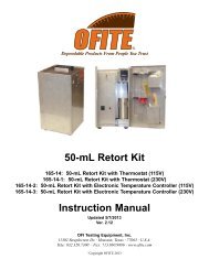
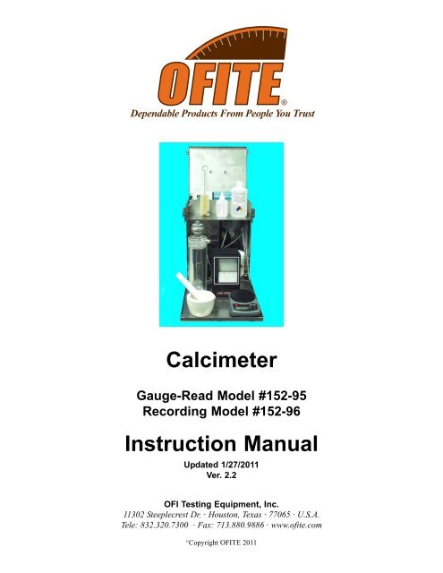
Calcimeter<br />
Gauge-Read Model #152-95<br />
Recording Model #152-96<br />
Instruction Manual<br />
Updated 1/27/2011<br />
Ver. 2.2<br />
<strong>OFI</strong> <strong>Testing</strong> <strong>Equipment</strong>, <strong>Inc</strong>.<br />
11302 Steeplecrest Dr. · Houston, Texas · 77065 · U.S.A.<br />
Tele: 832.320.7300 · Fax: 713.880.9886 · www.ofite.com<br />
©<br />
Copyright <strong>OFI</strong>TE 2011
Table of<br />
Contents<br />
Intro.......................................................................................................2<br />
Description...........................................................................................2<br />
Components.........................................................................................3<br />
Safety ....................................................................................................4<br />
Setup.....................................................................................................5<br />
Recording Calcimeter ......................................................................5<br />
Gauge-Read Calcimeter ..................................................................6<br />
Test Procedure....................................................................................7<br />
Creating a Calibration Curve..............................................................9<br />
Chart Recorder...................................................................................11<br />
Maintenance.......................................................................................13<br />
<strong>OFI</strong>TE, 11302 Steeplecrest Dr., Houston, TX 77065 USA / Tel: 832-320-7300 / Fax: 713-880-9886 / www.ofite.com 1
Intro<br />
The <strong>OFI</strong>TE Gauge-Read Calcimeter and the <strong>OFI</strong>TE Recording Calcimeter<br />
are used to determine the amount of Calcium Carbonate (CaCO 3 ) and<br />
Magnesium Carbonate (Dolomite) in a sample of alkaline earth carbonates<br />
such as oil well cores or drilled cuttings. Calcite build up in drilling fluids<br />
and in water treatment processes causes scaling problems. Data from the<br />
<strong>OFI</strong>TE Calcimeters can help determine the proper chemical treatment.<br />
These instruments comply with the ASTM D 4373 - 84 (Reapproved 1990)<br />
Standard Test Method for Calcium Carbonate Content in Soils. This test<br />
method is under the jurisdiction of ASTM Committee D-18 on Soil and Rock<br />
and is the direct responsibility of Subcommittee D -18.13 on Marine<br />
Geotechnics, published July 1984.<br />
Description<br />
In the <strong>OFI</strong>TE Calcimeter, calcium carbonate and magnesium carbonate are<br />
reacted with 10 percent hydrochloric acid in a sealed reaction cell to form<br />
CO 2 . As the CO 2 is released, the pressure build up is measured using<br />
either a pressure gauge or a pressure recorder. During the calibration<br />
process, a calibration curve is created by reacting HCl with pure, reagentgrade<br />
CaCO 3 . By using a known weight of CaCO 3 reagent, you can determine<br />
the relationship between the amount of pressure released and the<br />
weight of CaCO 3 in the sample. Since all reaction cells are slightly different,<br />
this relationship will be different for each cell. Therefore a calibration<br />
curve is required to obtain accurate results.<br />
The calcium carbonate content of soil (ASTM Procedure D 4373) is determined<br />
by treating a 1 g dried soil specimen with HCl in the reactor cell.<br />
The resulting pressure increase is then measured and compared to the calibration<br />
curve to determine the total weight of CaCO 3 in the test sample.<br />
The <strong>OFI</strong>TE Gauge-Read Calcimeter (152-95) features a pressure gauge on<br />
top of the reaction cell. With this model, the pressure within the reaction<br />
must be manually read from this gauge.<br />
The <strong>OFI</strong>TE Recording Calcimeter (152-96) includes a transducer and a<br />
chart recorder that automatically records the pressure readings without<br />
user intervention. This model was designed to make the test procedure<br />
easier by enabling you to run it virtually unattended.<br />
<strong>OFI</strong>TE, 11302 Steeplecrest Dr., Houston, TX 77065 USA / Tel: 832-320-7300 / Fax: 713-880-9886 / www.ofite.com 2
Gauge-Read Calcimeter (152-95):<br />
Components<br />
#142-54 O-ring<br />
#152-95-1 Gauge with Cover, 30 PSI, 4" Diameter<br />
#152-95-2 Bleed-Off Screw<br />
#152-95-3 Cell Cap<br />
#152-95-4 Reaction Cell<br />
#152-95-5 O-ring, 1 3 ⁄8" × 1 ⁄16"<br />
#152-95-6 Sample Cup<br />
Recording Calcimeter (152-96):<br />
#152-95 Calcimeter<br />
#142-54 O-ring<br />
#152-95-2 Bleed-Off Screw<br />
#152-95-3 Cell Cap<br />
#152-95-4 Reaction Cell<br />
#152-95-5 O-ring, 1 3 ⁄8" × 1 ⁄16"<br />
#152-95-6 Sample Cup<br />
#141-17 Clip for Graduated Cylinder<br />
#152-37 AC Power Cord, 3-Conductor<br />
#152-95 Calcimeter<br />
#152-96-2 Minigraph Recorder<br />
#152-96-3 Stainless Steel Case<br />
#152-96-4 Chart Paper for Minigraph<br />
#152-96-5 Pressure Transducer<br />
#152-96-6 Porcelain Mortar, 65 mL<br />
#152-96-7 Porcelain Pestle<br />
#152-96-8 #30 Gear Train<br />
#152-96-10 Power Supply<br />
#152-96-11 Female Cable Jack<br />
#152-96-12 Male Cable Plug<br />
#152-96-13 Insulated Banana Plug, Black<br />
#152-96-14 Insulated Banana Plug, Red<br />
#153-02 Brush; Graduate; 1 1 ⁄2" × 10 3 ⁄4"<br />
#153-18 Glass Graduated Cylinder 10 mL × 2 ⁄10 mL<br />
#153-55 Silicone Stopcock Grease, 150 g Tube (Dow Corning)<br />
#166-03 Hand-held Balance, 0 - 320 g (0.1g)<br />
#275-03 *Hydrochloric Acid; 10%; 8 oz (UN #1789)<br />
#280-00 Wetting Agent; 1 oz<br />
#285-00-1 Calcium Carbonate; 100 g<br />
<strong>OFI</strong>TE, 11302 Steeplecrest Dr., Houston, TX 77065 USA / Tel: 832-320-7300 / Fax: 713-880-9886 / www.ofite.com 3
Safety<br />
!<br />
Important<br />
The Calcimeter test relies on the reaction of CaCO 3 with hydrochloric acid.<br />
Hydrochloric acid is corrosive and may cause chemical burns. Use care in<br />
handling the acid. Avoid contact with skin, eyes, and clothing. In the event<br />
of exposure to skin or eyes, immediately flush with large quantities of water<br />
for at least 15 minutes. Do not inhale vapors. Process hydrochloric acid<br />
beneath a laboratory hood or in a well ventilated area to reduce the risk of<br />
inhalation. Wear appropriate safety equipment at all times.<br />
Do not take internally. In the event of accidental exposure, get medical<br />
attention immediately.<br />
Refer to the Material Safety Data Sheet (MSDS) for more information<br />
on Hydrochloric Acid.<br />
The <strong>OFI</strong>TE Recording Calcimeter uses an electrically powered transducer<br />
and recorder to record the pressure in the reaction cell. Observe the following<br />
safety considerations at all times:<br />
1. Make sure the power switch is off before connecting the power cable to<br />
an electrical outlet.<br />
2. Make sure you are using a three-wire grounding type power cable and<br />
outlet.<br />
3. Always unplug the power cable before opening the recorder to replace<br />
chart paper or any other maintenance or repair work.<br />
<strong>OFI</strong>TE, 11302 Steeplecrest Dr., Houston, TX 77065 USA / Tel: 832-320-7300 / Fax: 713-880-9886 / www.ofite.com 4
Setup<br />
Recording Calcimeter<br />
1. Begin by carefully unpacking the equipment. Inspect each piece to<br />
ensure everything is clean and in good operating condition. Inspect the<br />
cell cap o-ring for cracks or wear.<br />
2. Verify that the chart recorder has enough paper and that it is loaded<br />
properly. For more information, see the “Chart Recorder” section on<br />
page 2.<br />
3. Plug the power supply into the back of the chart recorder. Make sure<br />
the red cord goes into the red plug and the black cord goes into the<br />
black plug.<br />
To Transducer<br />
To Chart Recorder<br />
To Power Supply<br />
To AC Power Outlet<br />
Power Supply<br />
Chart Recorder<br />
4. Connect the transducer to the power supply. The cable connectors are<br />
keyed to prevent an incorrect connection. Be sure to tighten the cable<br />
lock to keep the connection secure.<br />
5. Plug the chart recorder and power supply into an appropriate AC power<br />
outlet.<br />
Transducer<br />
Cell Cap<br />
Bleed Valve<br />
O-ring<br />
To Power Supply<br />
Power Supply<br />
(Female)<br />
Transducer<br />
(Male)<br />
<strong>OFI</strong>TE, 11302 Steeplecrest Dr., Houston, TX 77065 USA / Tel: 832-320-7300 / Fax: 713-880-9886 / www.ofite.com 5
Setup<br />
Gauge-Read<br />
Calcimeter<br />
1. Begin by carefully unpacking the equipment. Inspect each piece to<br />
ensure everything is clean and in good operating condition. Inspect the<br />
cell cap o-ring for cracks or wear.<br />
Gauge<br />
Cell Cap<br />
Bleed Valve<br />
O-ring<br />
<strong>OFI</strong>TE, 11302 Steeplecrest Dr., Houston, TX 77065 USA / Tel: 832-320-7300 / Fax: 713-880-9886 / www.ofite.com 6
Test<br />
Procedure<br />
Before starting the test procedure, make sure the equipment is clean and in<br />
good operating condition. Verify that a calibration curve is available for the<br />
particular equipment to be used. If a calibration curve is not available, see<br />
the “Creating a Calibration Curve” section on page 8 to construct one.<br />
1. Obtain a sample of core, drilled cuttings, or other solids that are to be<br />
analyzed. The sample should be dry and free of contaminants. Grind<br />
the sample to 100 mesh or finer, using a mortar and pestle and a 100-<br />
mesh sieve. If you do not know whether the sample has been dried,<br />
heat it in an oven at 220°F (105°C) for 12 to 24 hours.<br />
2. Weigh approximately 1.0 - 1.4 g of the sample to the nearest .001 g.<br />
3. Load the test sample in the reactor cell.<br />
a. Unscrew and remove the cell cap. Remove the acid cup from the<br />
reaction cell.<br />
b. Inspect the reaction cell and top. Make sure both are clean and dry.<br />
c. Make sure the reaction cell o-ring on the top and the o-ring on the<br />
bleed valve are in good condition. Use a light coating of vacuum<br />
grease on the o-ring seals. Make sure all pipes or tubing connections<br />
are tight and do not leak.<br />
d. Hold the reaction cell in a horizontal position and slide one piece of<br />
paper and its sample to the bottom. Brush the paper with a small<br />
brush to remove traces of the sample, then remove the paper.<br />
e. Fill the acid cup with 20 mL 10% hydrochloric acid. Carefully place<br />
the cup into the cell. Be careful not to spill the HCl or get any on<br />
the bottom of the cup.<br />
f. Hand tighten the cell cap. Be careful not to splash any acid onto<br />
the sample.<br />
g. Open the bleed valve until the pressure reading is zero. Then close<br />
the bleed valve tightly.<br />
4. Turn the reaction cell back to vertical and start timing the test. This will<br />
start the reaction between the HCl and the CaCO 3 .<br />
<strong>OFI</strong>TE, 11302 Steeplecrest Dr., Houston, TX 77065 USA / Tel: 832-320-7300 / Fax: 713-880-9886 / www.ofite.com 7
5. At 30 seconds, record the pressure as “CaCO 3 Pressure”. If the test<br />
sample contains any dolomite, there will be a pause, then a slow, second<br />
rise in pressure. Swirl the reaction cell and allow sufficient time for<br />
the reaction to finish. The reaction is complete when the pressure<br />
stops increasing. This should happen in 30 to 45 minutes. The final<br />
pressure value is the total CaCO 3 pressure plus the dolomite pressure.<br />
To calculate the dolomite pressure, subtract the CaCO 3 pressure (30<br />
second reading) from the total pressure (30 - 45 minute reading).<br />
6. Refer to the graph below to interpret the pressure readings.<br />
7. Use the equations below to calculate the percentages of CaCO 3 and<br />
dolomite. For values of “Slope” refer to the “Creating a Calibration<br />
Curve” section below.<br />
%CaCO 3 =<br />
(Pressure Reading, PSI) (100)<br />
(Sample Weight) (Average Slope)<br />
(Total Pressure - CaCO 3 Pressure) (100) (.92)<br />
%Dolomite =<br />
(Sample Weight) (Average Slope)<br />
<strong>OFI</strong>TE, 11302 Steeplecrest Dr., Houston, TX 77065 USA / Tel: 832-320-7300 / Fax: 713-880-9886 / www.ofite.com 8
Creating a<br />
Calibration<br />
Curve<br />
The volume of a calcimeter reaction cell determines the relationship<br />
between the pressure increase and the amount of CO 2 released. This relationship<br />
is constant for a given reaction cell. The calibration curve and calculated<br />
calibration factor are used to convert the amount of pressure<br />
released into a percentage of calcium carbonate. All points on the calibration<br />
curve represent 100% CaCO 3 (for that sample weight). Any number of<br />
samples can be used to construct the calibration curve. The following are<br />
recommended for accuracy.<br />
1. Prepare five sets of duplicate specimens with the following masses of<br />
CaCO 3 :<br />
0.2 ± 0.01 g<br />
0.4 ± 0.01 g<br />
0.6 ± 0.01 g<br />
0.8 ± 0.01 g<br />
1.0 ± 0.01 g<br />
2. Load a calibration sample.<br />
Perform the procedure outlined in the “Test Procedure”, step 3.<br />
<br />
Tip<br />
3. Tip the cell and allow acid to run out of the cup onto the sample. Swirl<br />
the cell gently and continuously until a constant pressure is obtained.<br />
This will take at least 10 minutes. Keep the reactants in the lower part<br />
of the cell to avoid getting acid into the pressure gauge or pressure<br />
transducer. As soon as the reaction has started, observe the rapidly<br />
rising pressure. Record the peak pressure to the nearest 0.1 PSI (0.5<br />
kPa) as the CaCO 3 pressure for the sample weight used.<br />
If a mechanical shaker is available, it may be used to agitate the cell<br />
rather than swirling the reactants. Agitate the sample for 10 minutes.<br />
4. Repeat steps 2 and 3 for each of the remaining samples you prepared<br />
in step 1.<br />
5. For each sample create a plot on linear graph paper. On the x-axis plot<br />
grams of CaCO 3 and on the y-axis plot the final pressure in PSI. Draw<br />
a straight line through the average of the points. The graph on page 9<br />
shows a sample calibration curve.<br />
6. Because the relationship between pressure and sample size is linear,<br />
you may assume the curve to be a straight line with a constant slope.<br />
As the graph on page 9 illustrates, the slope of the curve is 2 PSI / .1 g<br />
CaCO 3 , or 20 PSI / 1.0 g CaCO 3 , resulting in a slope of 20. Therefore,<br />
the calibration factor is .05 × 100 = 5. This number is the slope or average<br />
slope for the equipment. It is a function of the volume of the reaction<br />
cell.<br />
<strong>OFI</strong>TE, 11302 Steeplecrest Dr., Houston, TX 77065 USA / Tel: 832-320-7300 / Fax: 713-880-9886 / www.ofite.com 9
Sample Calibration Curve<br />
As shown by the equations below, the slope can be written as a “Cell<br />
Factor” to multiply the pressure reading by to directly obtain percentages<br />
of Calcium Carbonate and Dolomite.<br />
As described above Slope = 20 PSI for a 1g sample therefore<br />
(Pressure) (100)<br />
% CaCO 3 = = 5 × Pressure<br />
(1 g) (20)<br />
% Dolomite =<br />
or<br />
(Total Pressure - CaCO 3 Pressure)(.92)(100)<br />
(1 g × 20)<br />
% Dolomite = 4.6 × (Total Pressure - CaCO 3 Pressure)<br />
<strong>OFI</strong>TE, 11302 Steeplecrest Dr., Houston, TX 77065 USA / Tel: 832-320-7300 / Fax: 713-880-9886 / www.ofite.com 10
Chart<br />
Recorder<br />
The <strong>OFI</strong>TE Recording Calcimeter differs from the pressure gauge model<br />
only in that a pressure transducer and small strip chart recorder are provided<br />
to replace the pressure gauge. It is highly recommended that you carefully<br />
read the instruction manual for the chart recorder before attempting to<br />
use the equipment.<br />
The unit is a Love Controls 1200 series Minigraph Recorder. It uses an<br />
“inkless writing system”, which uses a metal stylus to tap a dotted line on<br />
pressure sensitive chart paper. It has been adapted for use with the<br />
Calcimeter by adding a pressure transducer and power supply. The unit<br />
will record the pressure changes within the reactor cell as they occur. The<br />
percentage of calcium carbonate and dolomite can be calculated by applying<br />
the calibration factor to the chart reading.<br />
The transducer in the chart recorder has a range from 0 to 15 PSI.<br />
However, the chart readings represent milliamperes, not pressure. In order<br />
to convert the reading to PSI, figure the percentage of full scale that is<br />
being displayed. Then multiply that percentage by 15. This will give you<br />
the PSI reading.<br />
The chart paper included with the recorder shows 10 large divisions. If the<br />
chart paper shows a value on the third division (30% of full scale), the pressure<br />
reading is 4.5 PSI (15 PSI × .3 = 4.5).<br />
There are two methods for installing chart paper. The Reroll method routes<br />
the chart onto a roller for storage and review at a later time. The Feed<br />
Through method routes the chart upwards through the top of the door so<br />
that it may be viewed easily during recording. <strong>OFI</strong>TE recommends using<br />
the Feed Through method.<br />
1. Remove all signal and power inputs to the instrument before changing<br />
the chart paper.<br />
2. Press down on the door release latch and carefully swing the door<br />
downward.<br />
Door Release Latch<br />
<strong>OFI</strong>TE, 11302 Steeplecrest Dr., Houston, TX 77065 USA / Tel: 832-320-7300 / Fax: 713-880-9886 / www.ofite.com 11
3. Flip the chassis latch outward.<br />
4. Roll the o-rings from the center of the feed through the roller to fit<br />
into the groove on each side of the roller.<br />
5. Flip up the roller retaining lock clips.<br />
6. Remove the supply roller from the instrument. Slide the supply<br />
roller into the perforated end of a roll of chart paper.<br />
7. Hold the loose end of the chart paper in your left hand and the supply<br />
roll in your right hand so that the blank side of the chart paper is<br />
facing upward between your left hand and the roller. Slip the chart<br />
paper under the right hand side plate. Carefully maneuver the chart<br />
paper so that the perforations fit into the sprocket and drive rollers.<br />
8. Press the supply roll tension arm toward the left side plate. Set the<br />
supply roller pins into the notches of the side plates and snap the<br />
roller retaining lock clips down into the lock position.<br />
9. Pull the chart paper out from the supply roll until it extends out<br />
beyond the top of the door.<br />
10. Press down on the right-hand side plate. Flip the chassis latch up<br />
(press the latch against the side plate until it snaps into place).<br />
Close the door. Reconnect the signal and power cables. Rotate<br />
the thumbwheel on the outside of the door to advance the chart<br />
paper as desired.<br />
Supply Roller<br />
Supply Roll<br />
Reroll Roller<br />
Roller Retaining<br />
Lock Clip<br />
Chassis Latch<br />
Right-Hand Side Plate<br />
<strong>OFI</strong>TE, 11302 Steeplecrest Dr., Houston, TX 77065 USA / Tel: 832-320-7300 / Fax: 713-880-9886 / www.ofite.com 12
Maintenance<br />
After each test, thoroughly clean the cell and acid cup with water and a<br />
mild soap. Use only alcohol-free cleaners. Alcohol can damage the plexiglass<br />
cell.<br />
<strong>Testing</strong> For Leaks<br />
Leaks in the pressure system are the most common case of inaccurate<br />
readings.<br />
1. Periodically inspect the reaction cell and replace the o-rings if they<br />
are dry, cracked, or worn.<br />
2. Clean the pipe-thread connection between the reaction cell top and<br />
the pressure gauge or transducer with a brush and soap suds. If<br />
repairs are necessary, disassemble the pipe-threaded connection<br />
between the reaction cell and the gauge or transducer. Use teflon<br />
tape to re-seal the connection.<br />
3. Check for plugging in the connection between the reaction cell and<br />
the gauge or transducer. Also check the gauge entrance or the<br />
transducer barrel and diaphragm for build-up of calcium deposit<br />
over long periods of time. A warm Chlorox wash should clean these<br />
parts.<br />
4. To check for leaks, pressurize the instrument as described in<br />
“Creating a Calibration Curve” above using a .6 g sample. Let the<br />
unit stand for at least one hour. The pressure within the reaction<br />
cell should remain stable unless leaks are present.<br />
Calibration Data Does Not Give a Straight-Line<br />
If there are no leaks in the system, but results are not giving a straightline<br />
calibration curve or data is otherwise questionable, check the following:<br />
1. Make sure the scale or balance is clean. Shield the balance from<br />
air currents and vibration as much as possible when weighing samples<br />
or CaCO 3 for calibration.<br />
2. Check the reaction cell for contaminants. Be sure the cell is clean<br />
and dry.<br />
3. Check for impurities in reagents. Moisture in CaCO 3 will result in<br />
low-pressure readings.<br />
<strong>OFI</strong>TE, 11302 Steeplecrest Dr., Houston, TX 77065 USA / Tel: 832-320-7300 / Fax: 713-880-9886 / www.ofite.com 13
Recorder Not Responding To Pressure Changes In Reaction Cell.<br />
1. Make sure the power cable is plugged into the electrical outlet and<br />
that power is available at the outlet.<br />
2. Verify the power switch on the recorder is ON.<br />
3. Check the plug and receptacle going into the recorder to make sure<br />
they are making a good connection.<br />
4. Check the plug and receptacle connecting the transducer to the<br />
recorder. Make sure this plug and receptacle are making a good<br />
connection.<br />
<strong>OFI</strong>TE, 11302 Steeplecrest Dr., Houston, TX 77065 USA / Tel: 832-320-7300 / Fax: 713-880-9886 / www.ofite.com 14