127-00 - Reservoir Permeability Tester - OFI Testing Equipment, Inc.
127-00 - Reservoir Permeability Tester - OFI Testing Equipment, Inc.
127-00 - Reservoir Permeability Tester - OFI Testing Equipment, Inc.

Create successful ePaper yourself
Turn your PDF publications into a flip-book with our unique Google optimized e-Paper software.
<strong>Reservoir</strong> <strong>Permeability</strong> <strong>Tester</strong><br />
Part No. <strong>127</strong>-<strong>00</strong><br />
Instruction Manual<br />
Updated 10/2/2012<br />
Ver. 1.7<br />
<strong>OFI</strong> <strong>Testing</strong> <strong>Equipment</strong>, <strong>Inc</strong>.<br />
11302 Steeplecrest Dr. · Houston, Texas · 77065 · U.S.A.<br />
Tele: 832.320.73<strong>00</strong> · Fax: 713.880.9886 · www.ofite.com<br />
©<br />
Copyright <strong>OFI</strong>TE 2012
Table of<br />
Contents<br />
Intro.......................................................................................................2<br />
Description...........................................................................................2<br />
Specifications ......................................................................................3<br />
Components.........................................................................................4<br />
Safety ....................................................................................................5<br />
Preparation...........................................................................................6<br />
Loading the Core .............................................................................8<br />
Treating Fluid ...................................................................................9<br />
Filling the Transducer System .......................................................10<br />
Priming the Waters Pump ..............................................................11<br />
Operation............................................................................................12<br />
Reversing Direction of Flow...........................................................14<br />
Running Fluids in Series................................................................15<br />
Shut-Down Procedure....................................................................16<br />
Software..............................................................................................17<br />
Options...........................................................................................18<br />
Calibration ......................................................................................19<br />
Configuring Eurotherms.................................................................20<br />
Operation .......................................................................................21<br />
Appendix ............................................................................................22<br />
Pressure <strong>Testing</strong> ............................................................................22<br />
Calculations....................................................................................23<br />
Cleaning .........................................................................................24<br />
Storing the RPT .............................................................................25<br />
<strong>OFI</strong>TE, 11302 Steeplecrest Dr., Houston, TX 77065 USA / Tel: 832-320-73<strong>00</strong> / Fax: 713-880-9886 / www.ofite.com 1
Intro<br />
The permeability of a petroleum reservoir is one of the most influential factors<br />
in determining the production capabilities of a producing formation.<br />
<strong>Permeability</strong> is a measure of the ability of a fluid to flow through a porous<br />
media when subjected to a differential pressure and is mathematically<br />
equated by Darcy's law.<br />
The <strong>Reservoir</strong> <strong>Permeability</strong> <strong>Tester</strong> (RPT) is a high-temperature, high-pressure<br />
test apparatus designed to measure formation (core) response to acid,<br />
brines, oils, or gas.<br />
Description<br />
The RPT consists of three pressuring systems: confining pressure, drive<br />
pressure, and back pressure. Confining pressure surrounds the core<br />
specimen with water and prevents the treating fluids from going around the<br />
side of the core or escaping through the sides. The drive pressure is controlled<br />
by the Waters pump and uses kerosene as a hydraulic fluid to push<br />
the treating fluids through the core. The back pressure is set just high<br />
enough to keep the treating fluids from boiling at the test temperature.<br />
At the beginning of a test, confining pressure and back pressure are<br />
applied to the core during the heating process. When the core reaches<br />
test temperature, the Waters pump is turned on and hydraulic fluid is<br />
pumped into one of three 1.5-liter stainless steel accumulators. The accumulator<br />
contains a floating piston that separates the hydraulic fluid from the<br />
treating fluid. As the hydraulic fluid is pumped in, the treating fluid is<br />
pumped out and through the core specimen. A transducer measures the<br />
pressure going into the core and the pressure coming out of the core and<br />
displays the difference on the front panel of the unit.<br />
During the test, the flow of pressure can be diverted into any of the three<br />
accumulators, allowing for the testing of multiple treating fluids. In order to<br />
test return permeability, the direction of the flow can also be reversed,<br />
sending the treating fluid through the core in the opposite direction.<br />
All data is simultaneously recorded and graphed on a PC, which can then<br />
store the data for later recall.<br />
<strong>OFI</strong>TE, 11302 Steeplecrest Dr., Houston, TX 77065 USA / Tel: 832-320-73<strong>00</strong> / Fax: 713-880-9886 / www.ofite.com 2
Specifications<br />
Size:<br />
Net Size:<br />
Net Weight:<br />
Crated Size:<br />
Crated Weight:<br />
44" × 20" × 45.5" (111.8 × 50.8 × 115.8 cm)<br />
519 lbs. (235.4 kg)<br />
51" × 31" × 60" (129.5 × 78.7 × 152.4 cm)<br />
726 lbs. (329 kg)<br />
Maximum Pressure:<br />
Drive:<br />
5,<strong>00</strong>0 PSI (34.5 MPa)<br />
Confining: 5,<strong>00</strong>0 PSI (34.5 MPa)<br />
Back Pressure: 1,<strong>00</strong>0 PSI (6.9 MPa)<br />
Temperature Controller:<br />
2 Digital PID with 1° Resolution; Max 4<strong>00</strong>°F (204.4°C)<br />
System Requirements:<br />
Air: 1<strong>00</strong> - 120 PSI (689.5 - 827.4 kPa)<br />
Nitrogen: 1,<strong>00</strong>0 - 2,<strong>00</strong>0 PSI (6.9 - 13.8 MPa)<br />
Water: 30 - 40 PSI (206.9 - 275.8 kPa)<br />
Electrical: 230 VAC<br />
<strong>OFI</strong>TE, 11302 Steeplecrest Dr., Houston, TX 77065 USA / Tel: 832-320-73<strong>00</strong> / Fax: 713-880-9886 / www.ofite.com 3
#<strong>127</strong>-<strong>00</strong>-205 Accumulator Cap and Piston O-ring; Qty: 12<br />
Components<br />
#<strong>127</strong>-<strong>00</strong>-210 Hassler Cell Cap Rod; Qty: 4<br />
#<strong>127</strong>-<strong>00</strong>-212 Hassler Cap O-ring; Qty: 2<br />
#<strong>127</strong>-<strong>00</strong>-213 Hassler Insert O-ring; Qty: 2<br />
#<strong>127</strong>-<strong>00</strong>-235 1.5" Viton Core Boot for Hassler Cell; Qty: 2<br />
#<strong>127</strong>-<strong>00</strong>-247 75 mL Sample Cylinder with ¼" FNPT Ports; Qty: 2<br />
#<strong>127</strong>-<strong>00</strong>-310 Accumulator Fill Pump; 230V<br />
#130-75-71 Monitor<br />
#130-75-74 Desktop Computer<br />
#130-76-03 Thermocouple<br />
#130-79-15 Serial Cable; OB9 M/F<br />
#130-79-16 USB Cable<br />
#152-38 AC Power Cord; 3-Conductor; International (Continental<br />
Eurpoean); Qty: 3<br />
#166-05 230 Volt (European Plug) Adapter<br />
Optional:<br />
#<strong>127</strong>-02 Spare Parts for Two Years (Sold Separately):<br />
#120-27-<strong>00</strong>4 DP-15 Diaphragm (0 - 2<strong>00</strong> PSI / 0 - 1.4 MPa); Qty: 3<br />
#120-27-<strong>00</strong>5 DP-15 Diaphragm (0 - 5<strong>00</strong> PSI / 0 - 3.5 MPa); Qty: 3<br />
#120-27-<strong>00</strong>6 DP-15 Diaphragm (0 - 125 PSI / 0 - 861.9 kPa); Qty: 3<br />
#122-073-1 3-Amp Fuse; 5 mm × 20 mm; Qty: 12<br />
#122-074 4-Amp Fuse; 5 mm × 20 mm; Qty: 12<br />
#122-077 10-Amp Fuse; 5 mm × 20 mm; Qty: 6<br />
#<strong>127</strong>-<strong>00</strong>6 ISCO Pump Repair Kit<br />
#<strong>127</strong>-<strong>00</strong>-205 Accumulator Cap and Piston O-ring; Qty: 20<br />
#<strong>127</strong>-<strong>00</strong>-212 Hassler Cap O-ring; Qty: 72<br />
#<strong>127</strong>-<strong>00</strong>-213 Hassler Insert O-ring; Qty: 18<br />
#<strong>127</strong>-<strong>00</strong>-235 1.5" Viton Core Boot for Hassler Cell; Qty: 40<br />
#<strong>127</strong>-<strong>00</strong>-240 83 Series ¼" Three-Way Stainless Steel Ball Valve;<br />
6,<strong>00</strong>0 PSI (14.4 MPa); Qty: 2<br />
#<strong>127</strong>-<strong>00</strong>-242 83 Series ¼" Two-Way Stainless Steel Ball Valve;<br />
6,<strong>00</strong>0 PSI (14.4 MPa); Compression Fittings; Qty: 2<br />
#171-45-4 Thermocouple; Qty: 2<br />
<strong>OFI</strong>TE, 11302 Steeplecrest Dr., Houston, TX 77065 USA / Tel: 832-320-73<strong>00</strong> / Fax: 713-880-9886 / www.ofite.com 4
Safety<br />
The RPT is designed to test the effects of brines, acids, oils, or gas on core<br />
specimens at elevated temperatures and pressures. Read and understand<br />
these instructions completely before attempting to operate this equipment.<br />
Before beginning regular operation, make several trial runs using non-reactive<br />
fluids at moderate temperature and pressure to familiarize yourself with<br />
the operating procedure.<br />
When testing the effects of acids and brines on formation core specimens<br />
at simulated downhole conditions, it is important to adhere to the following<br />
safety precautions:<br />
1. Wear rubber gloves, eye protection, and a lab coat or apron at all<br />
times while operating the unit.<br />
2. All acids must be inhibited to prevent excessive corrosion and damage<br />
to the instrument.<br />
!<br />
Important<br />
3. At elevated temperatures, the confining pressure in the core holder<br />
will increase due to thermal expansion. The core holder has an<br />
emergency pressure release valve set to 5,2<strong>00</strong> PSI (35.9 MPa),<br />
which will prevent any damage to the sleeve. However, the core<br />
specimen may be destroyed if the pressure is not carefully monitored<br />
and controlled by the operator. Relieve the pressure buildup<br />
through the “Confining Pressure Release” valve.<br />
4. All tests fluids must be clean and contain no solids to avoid plugging<br />
and erosion of component parts.<br />
5. Before connecting the RPT to power, air, or water sources, make<br />
sure all of the valves are in the closed or “Off” position.<br />
6. The RPT has three separate pressuring systems, each with its own<br />
maximum pressure. Do not exceed these pressures:<br />
- Confining Pressure: 5,<strong>00</strong>0 PSI (34.5 MPa)<br />
- Pump Pressure: 5,<strong>00</strong>0 PSI (34.5 MPa)<br />
- Back Pressure: 1,<strong>00</strong>0 PSI (6.9 MPa)<br />
7. In the event of an emergency, immediately shut off the main power<br />
switch and close the air and nitrogen supply valves.<br />
<strong>OFI</strong>TE, 11302 Steeplecrest Dr., Houston, TX 77065 USA / Tel: 832-320-73<strong>00</strong> / Fax: 713-880-9886 / www.ofite.com 5
Preparation<br />
1. Carefully remove the unit from the crate and place it on a flat, level surface<br />
with access to air, water, nitrogen, and power sources.<br />
2. Connect the water, air, and nitrogen sources to the appropriate ports on<br />
the back of the unit. Plug the unit into a 220V power source.<br />
3. Place the PC near the RPT. Connect the PC to the RPT with the supplied<br />
serial cable.<br />
<strong>OFI</strong>TE, 11302 Steeplecrest Dr., Houston, TX 77065 USA / Tel: 832-320-73<strong>00</strong> / Fax: 713-880-9886 / www.ofite.com 6
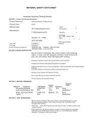
Gas Flow Rate<br />
Crossover Valve<br />
Confining Pressure Drive Pressure<br />
Accumulator<br />
Transducer<br />
Temp<br />
Isolation<br />
Valves<br />
Waters<br />
Pump<br />
Pump<br />
Regulator<br />
Bypass<br />
Valve<br />
Core<br />
Holder<br />
Nitrogen Regulator<br />
Back Pressure Gauge<br />
Back Pressure Valve<br />
Confining Pressure Drain<br />
<strong>OFI</strong>TE, 11302 Steeplecrest Dr., Houston, TX 77065 USA / Tel: 832-320-73<strong>00</strong> / Fax: 713-880-9886 / www.ofite.com 7
Preparation<br />
Loading the Core<br />
1. The RPT is designed to test core specimens 1½" (3.8 cm) in diameter<br />
and between 3.75" (9.5 cm) and 6" (15.2 cm) long. Core specimens<br />
should be prepared using a 1.5" (3.8 cm) core drill and the ends should<br />
be sawed or milled so that they are parallel and as perpendicular to the<br />
sides as possible.<br />
2. The core specimen should be saturated in a synthetic or natural formation<br />
brine to simulate “in-situ” treatment of the formation.<br />
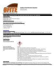
3. Place the core specimen into the rubber sleeve. Use the supplied<br />
stainless steel spacers to fill in the gaps on the ends of the core inside<br />
the rubber sleeve. Allow at most ½" of exposed rubber on each end of<br />
the core specimen.<br />
Stainless Steel Spacer Spacer in Sleeve Core in Sleeve<br />
4. Seat the core holder assembly firmly over the post of the bottom pressure<br />
head in the core holder.<br />
5. Slowly tighten the top pressure head, making sure it seats into the rubber<br />
sleeve. Tighten the assembly firmly to allow the o-ring to seal.<br />
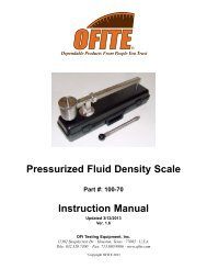
6. Connect the pressure lines to the VCO connectors on the top pressure<br />
head.<br />
Note<br />
Make sure the o-rings are in place and in good condition. The connectors<br />
that house the o-rings have special caps to protect the o-rings.<br />
Remove the caps and keep them in a safe place during testing. They<br />
will be needed when testing is complete.<br />
VCO Connection<br />
Thermocouple Port<br />
VCO Connection<br />
with Protective Plug<br />
7. Insert the thermocouple into the thermocouple port, but do not tighten it<br />
in place yet.<br />
<strong>OFI</strong>TE, 11302 Steeplecrest Dr., Houston, TX 77065 USA / Tel: 832-320-73<strong>00</strong> / Fax: 713-880-9886 / www.ofite.com 8
Preparation<br />
Treating Fluid<br />
!<br />
Important<br />
This RPT contains three, 1.5-liter stainless steel accumulators. These contain<br />
a floating piston which separates the treating fluid from the drive fluid.<br />
Correct preparation of the treating fluid will minimize equipment failure and<br />
prolong the life of the equipment.<br />
1. Make sure all treating fluids are clean and free of any solids.<br />
Do not put mud into an accumulator.<br />
2. All acids should be inhibited. Do not leave acids in the system for<br />
extended periods of time.<br />
3. Before running your first test, designate an accumulator for each type of<br />
fluid (brine, hydrocarbon, etc.) to be tested. In each accumulator, use<br />
the same type of fluid in every test. This will prevent the different fluids<br />
from mixing and adversely affecting the results.<br />
4. Before loading an accumulator, make sure it is empty and that no pressure<br />
is on the system.<br />
5. Fill the accumulators using the supplied piston metering pump.<br />
a. Place the inlet end of the pump into the treating fluid.<br />
b. Run the pump until the fluid comes out the discharge end.<br />
c. Stop the pump.<br />
d. Connect the discharge end of the pump to the fill port located above<br />
the accumulator.<br />
e. Set the valve on the top of the accumulator to “Fill”. Set the valve<br />
below the accumulator to “<strong>Reservoir</strong>”. Both of these valves should<br />
be pointing to the left.<br />
f. Turn on the pump. The pump will automatically stop when the<br />
accumulator is full.<br />
Note<br />
As the accumulator fills, drive fluid will be pushed into the reservoir.<br />
The marks on the side of the reservoir show the level of drive fluid<br />
inside. When all three accumulators are full, the drive fluid should<br />
reach the top mark.<br />
6. Set both valves on the accumulator to “Off”.<br />
7. Repeat this procedure for each accumulator.<br />
<strong>OFI</strong>TE, 11302 Steeplecrest Dr., Houston, TX 77065 USA / Tel: 832-320-73<strong>00</strong> / Fax: 713-880-9886 / www.ofite.com 9
Preparation<br />
Filling the Transducer<br />
System<br />
The transducer uses a highly-sensitive electronic pressure diaphragm<br />
which can be damaged if corroded by brines or acids and may transmit<br />
incorrectly if contaminated with foreign particles. Maintaining a sufficient<br />
amount of clean fluid in the isolation system will increase the life of the<br />
transducer diaphragm.<br />
1. Make sure no pressure is on the system.<br />
2. Close the two “Isolation” valves.<br />
3. Disconnect the two isolation tanks from the transducer.<br />
4. With a syringe, inject enough glycerin to completely fill the tanks.<br />
5. Reconnect the isolation tanks to the transducer.<br />
6. Loosen the two allen screws on the sides of the transducer.<br />
7. Open the isolation valves and apply a small amount of pressure to the<br />
system.<br />
8. When fluids starts to leak from the transducer, quickly tighten the allen<br />
screws. This will ensure no air is trapped in the system.<br />
Isolation Tanks<br />
Transducer<br />
Disconnect Here<br />
Isolation Valves<br />
Bypass Valves<br />
<strong>OFI</strong>TE, 11302 Steeplecrest Dr., Houston, TX 77065 USA / Tel: 832-320-73<strong>00</strong> / Fax: 713-880-9886 / www.ofite.com 10
Preparation<br />
Priming the Waters<br />
Pump<br />
Before using the RPT for the first time, you must prime the Waters pump.<br />
1. Insert an empty syringe into the priming port in the center of the pump.<br />
2. Turn the priming knob counter-clockwise.<br />
3. Pull the plunger of the syringe out until you see fluid enter the syringe.<br />
This may take several tries.<br />
4. Remove the syringe and tighten the priming knob.<br />
Priming Port<br />
Priming Knob<br />
<strong>OFI</strong>TE, 11302 Steeplecrest Dr., Houston, TX 77065 USA / Tel: 832-320-73<strong>00</strong> / Fax: 713-880-9886 / www.ofite.com 11
Operation<br />
Once the accumulators are full, the core holder is loaded, and the pump is<br />
primed, you are ready to begin a test.<br />
1. Turn the “Power” switch on.<br />
2. Set both “Liquid/Gas” valves to the appropriate position, depending<br />
on your test.<br />
3. Turn the “Nitrogen” valve on.<br />
4. Set the “Back Pressure” valve to “B.P. Open”. Turn the “Nitrogen<br />
Regulator” clockwise to set the back pressure high enough to prevent<br />
the treating fluid from boiling.<br />
5. Turn the “Back Pressure” valve to “B.P. Lock-in”. This will hold the<br />
back pressure at the current level throughout the test. The<br />
“Nitrogen Regulator” can now be used to control the drive pressure<br />
in a gas test.<br />
6. Keep a 5/8" wrench handy and turn the “Water” valve on. When<br />
water begins leaking from the thermocouple port, quickly tighten the<br />
thermocouple completely. This will ensure no air remains inside the<br />
core holder.<br />
7. Turn the “Pump Regulator” clockwise to set the confining pressure.<br />
Note<br />
!<br />
Important<br />
Make sure the “Confining Pressure Release” valve is off.<br />
8. Set the temperature controller to the desired test temperature.<br />
While the core holder is heating, carefully monitor the “Confining<br />
Pressure”. Bleed any excess pressure by slowly opening the<br />
“Confining Pressure Release” valve.<br />
9. Turn the “Air” valve on.<br />
10. If you are running a liquid test, set the pump to the desired flowrate.<br />
a. Press the “Edit” button.<br />
b. Use the arrow buttons to adjust the flowrate.<br />
c. Press the “Menu” button.<br />
<strong>OFI</strong>TE, 11302 Steeplecrest Dr., Houston, TX 77065 USA / Tel: 832-320-73<strong>00</strong> / Fax: 713-880-9886 / www.ofite.com 12
11. If you are running a gas test, use the “Nitrogen Regulator” to set the<br />
drive pressure.<br />
12. On the accumulator, turn the top valve to “Deliver” and the bottom<br />
valve to “Pump”. Both valves should be pointing to the right.<br />
13. Turn the pump on by pressing the “Run/Stop” button.<br />
14. Wait for the treating fluid to drain from the back pressure outlet on<br />
the right side of the unit.<br />
<br />
Tip<br />
!<br />
Important<br />
Be sure to have a container under the outlet to catch the fluid as it<br />
drains. If you are running a gas test, turn the outlet valve to point to<br />
the VCO connection and run a tube into a sealed container. This<br />
will prevent treatment fluid from spraying out of the outlet.<br />
Carefully monitor the amount of fluid release through the back pressure<br />
outlet. This will tell you how much fluid is left in the accumulator.<br />
Be sure to refill the accumulator before it gets empty.<br />
15. Open both “Isolation” valves at the same time.<br />
16. Again, wait for the treating fluid to drain from the back pressure outlet.<br />
Close the bypass valve. The “Differential Pressure” indicator<br />
will begin displaying the pressure differential.<br />
17. Start the test procedure in the RPT software. See page 21 for<br />
instructions.<br />
<strong>OFI</strong>TE, 11302 Steeplecrest Dr., Houston, TX 77065 USA / Tel: 832-320-73<strong>00</strong> / Fax: 713-880-9886 / www.ofite.com 13
Operation<br />
Reversing Direction of<br />
Flow<br />
For simulated formation treatment the operator may wish to inject treating<br />
fluid into one face of the core specimen then reverse the flow into the<br />
opposite face. This procedure can be repeated as needed.<br />
1. Turn off the pump.<br />
2. Open the “Bypass” valve to equalize the pressure.<br />
3. Turn the Crossover valve to “Reverse”.<br />
4. Close the “Bypass” valve.<br />
5. Turn the pump back on.<br />
<strong>OFI</strong>TE, 11302 Steeplecrest Dr., Houston, TX 77065 USA / Tel: 832-320-73<strong>00</strong> / Fax: 713-880-9886 / www.ofite.com 14
Operation<br />
Running Fluids in<br />
Series<br />
The RPT is equipped with three accumulators for up to three different treatment<br />
fluids. Treatment fluids can be switched during a test as often as<br />
needed.<br />
1. Stop the pump.<br />
2. In the RPT software, click the “Stop Run” button.<br />
3. Set both valves on the active accumulator to “Off”.<br />
4. Set the upper valve on the new accumulator to “Deliver”. Set the<br />
lower valve to “Pump”.<br />
5. In the RPT software, select the new fluid and click the “Start Run”<br />
button.<br />
6. Turn the pump back on.<br />
<strong>OFI</strong>TE, 11302 Steeplecrest Dr., Houston, TX 77065 USA / Tel: 832-320-73<strong>00</strong> / Fax: 713-880-9886 / www.ofite.com 15
Operation<br />
Shut-Down Procedure<br />
1. Turn off the pump.<br />
2. Lower the temperature set point to 0. Wait for the system to cool.<br />
3. Slowly turn the “Back Pressure” valve to “B.P. Open”. Turn the<br />
“Nitrogen Regulator” counter-clockwise to release the back pressure on<br />
the system. Wait for the drive fluid to finish draining from the back<br />
pressure outlet.<br />
4. Close both “Isolation” valves.<br />
5. Open the “Bypass” valve.<br />
6. Turn the top and bottom valves on the accumulator to “Off”.<br />
7. Slowly open and close the top and bottom valves on any other accumulators<br />
that were used in the test. This will release any remaining pressure<br />
in the lines.<br />
8. Turn off the “Water”, “Nitrogen”, and “Air” valves.<br />
<br />
Tip<br />
9. Slowly open the “Confining Pressure Release” valve.<br />
Be sure to have a container under the outlet to catch the water as it<br />
drains.<br />
10. Make sure all gauges read 0 PSI before continuing.<br />
11. Slowly unscrew the connections between the pressure lines and the<br />
VCO fixtures. Remove the lines and place the protective caps on the<br />
ends.<br />
12. Remove the thermocouple from the core holder.<br />
13. Open the core holder.<br />
14. Turn the red knob behind the core holder. This will release the swivel<br />
that holds the core holder in place. Tip the core holder to the left and<br />
pour out the water into a container.<br />
15. Remove the core from the core holder.<br />
<strong>OFI</strong>TE, 11302 Steeplecrest Dr., Houston, TX 77065 USA / Tel: 832-320-73<strong>00</strong> / Fax: 713-880-9886 / www.ofite.com 16
Software<br />
The <strong>OFI</strong>TE software for the <strong>Reservoir</strong> <strong>Permeability</strong> <strong>Tester</strong> is designed to<br />
automatically record the data from a permeability test, graph the results,<br />
and store the data for later retrieval.<br />
The software does not control the RPT unit. It performs data acquisition<br />
only.<br />
To open the software, double-click the icon on the PC desktop. You will<br />
now see the main screen.<br />
<strong>OFI</strong>TE, 11302 Steeplecrest Dr., Houston, TX 77065 USA / Tel: 832-320-73<strong>00</strong> / Fax: 713-880-9886 / www.ofite.com 17
Software<br />
Options<br />
To modify the software options, choose “Options” from the “Edit” menu.<br />
“COM PORT” - specifies the port the RPT is connected to<br />
“DAQ Time” - determines how often the software records data<br />
“Data File Directory” - Test data will be stored in this directory.<br />
“Temp Units” - Choose °F or °C.<br />
“Send Chart to Printer” - Check this box if you want charts to be printed to<br />
the printer.<br />
“Send Chart to File” - Check this box if you want charts to be saved to a file.<br />
<strong>OFI</strong>TE, 11302 Steeplecrest Dr., Houston, TX 77065 USA / Tel: 832-320-73<strong>00</strong> / Fax: 713-880-9886 / www.ofite.com 18
Software<br />
Calibration<br />
The RPT software will only require calibration after a new installation.<br />
Otherwise, this procedure is unnecessary.<br />
1. Choose “Calibration” from the “Utilities” menu.<br />
2. Under “Variable” choose “Sample Temp.”<br />
3. Enter the following values and then click the “Store Cal” button.<br />
Value Lo: 0<br />
Sig. Lo.: 0<br />
Value Hi: 2<strong>00</strong><br />
Sig. Hi: 2<strong>00</strong><br />
4. Now choose “Mass Flow Rate” from the “Variable” menu and enter<br />
these values. Click “Store Cal” when finished.<br />
Value Lo: 0<br />
Sig. Lo.: 4<br />
Value Hi: 9.999<br />
Sig. Hi: 20<br />
5. Now choose “Pressure” and enter these values. Click “Store Cal” when<br />
finished.<br />
Value Lo: 0<br />
Sig. Lo.: 0<br />
Value Hi: 5<strong>00</strong><br />
Sig. Hi: 5<br />
6. Click “Exit Cal” when you have entered all three sets of values.<br />
<strong>OFI</strong>TE, 11302 Steeplecrest Dr., Houston, TX 77065 USA / Tel: 832-320-73<strong>00</strong> / Fax: 713-880-9886 / www.ofite.com 19
Software<br />
Configuring<br />
Eurotherms<br />
Two Eurotherm indicators on the front panel display the “Gas Flow” and the<br />
“Differential Pressure”. The “Gas Flow” indicator should read 0 when their<br />
is no flow through the system. Likewise, when there is no pressure on the<br />
system, the “Differential Pressure” indicator should also read 0. Over time,<br />
the readings on these indicators may drift. When that happens, it will be<br />
necessary to configure the Eurotherms.<br />
1. Make sure there is no pressure on the system and that the “Air” valve is<br />
set to “OFF”.<br />
2. Open both “Isolation” valves and the “Bypass” valve.<br />
3. The “Gas Flow” and “Differential Pressure” indicators should both read<br />
0. If they do not, open “Configure Eurotherms” from the “Utilities” menu<br />
in the software.<br />
4. Choose an indicator to configure.<br />
a. To configure the “Gas Flow” indicator:<br />
i. Choose “Mass Flow”.<br />
ii.<br />
Adjust the “Offset” value until the “Gas Flow” indicator on the<br />
front panel reads 0.<br />
b. To configure the “Differential Pressure” indicator:<br />
i. Choose “Delta Pressure”.<br />
ii.<br />
If you have replaced the diaphragm in the transducer, enter the<br />
diaphragm minimum and maximum values in the “Value Low”<br />
and “Value High” fields and click “Apply Config”. Refer to the<br />
diaphragm documentation for these values.<br />
5. Click “OK”.<br />
If you have not replaced the diaphragm, do not changes the<br />
“Value Low” and “Value High” fields.<br />
iii. Adjust the “Offset” value until the “Gas Flow” indicator on the<br />
front panel reads 0.<br />
<strong>OFI</strong>TE, 11302 Steeplecrest Dr., Houston, TX 77065 USA / Tel: 832-320-73<strong>00</strong> / Fax: 713-880-9886 / www.ofite.com 20
Software<br />
Operation<br />
1. When starting a new test, first choose “Load Test” from the “Operate”<br />
menu and enter all the appropriate data. The core dimensions, fluid<br />
viscosity, and test name are required fields. These must be entered to<br />
achieve accurate results. All of the other fields are optional.<br />
2. Prepare the RPT unit according to the directions on page 8.<br />
3. When the unit is ready to begin the test, choose “Start Test” from the<br />
“Operate” menu. The file header is optional. Enter a file name and<br />
DAQ Time and click “OK”. The software will immediately start recording<br />
and the “Test Running” light will come on.<br />
4. You will now be back at the main screen. If you are running a liquid<br />
test, make sure the “Model” menu is set to “Liquid Perm”, then enter the<br />
flow rate from the pump into the “Flow Rate” field. If you are running a<br />
gas test, set the “Model” menu to “Gas Perm” and enter the back pressure<br />
into the “Back Pressure” field.<br />
5. When you switch treating fluid or flow direction, click the “Stop Run”<br />
button to pause recording. If you are switching fluid, select the new<br />
fluid from the drop-down list, then click the “Start Run” button to resume<br />
recording. This should all be done while the pump is stopped.<br />
6. When the test is finished, select “End Test” from the “Operate” menu.<br />
7. To access saved data from a previous test, select “Recall Chart” from<br />
the “Utilities” menu and choose the file you wish to review.<br />
<strong>OFI</strong>TE, 11302 Steeplecrest Dr., Houston, TX 77065 USA / Tel: 832-320-73<strong>00</strong> / Fax: 713-880-9886 / www.ofite.com 21
Appendix<br />
Pressure <strong>Testing</strong><br />
The RPT should be hydrostatically pressure tested to 5,<strong>00</strong>0 PSI (34.5 MPa)<br />
annually. Prolonged use at extreme temperatures and pressures may warrant<br />
a shorter time interval.<br />
1. Make sure all valves are closed and all gauges read zero.<br />
2. Disconnect the bottom pressure line from the Crossover valve.<br />
Plug the opening on the valve to prevent pressure from escaping.<br />
3. Turn the “Air” valve on.<br />
4. Choose a filled accumulator and set the top valve to “Deliver” and<br />
the bottom valve to “Pump”.<br />
5. Turn on the pump.<br />
6. Allow the drive pressure to reach 5,<strong>00</strong>0 PSI (34.5 MPa), then turn<br />
off the pump.<br />
7. Check for leaks throughout the system.<br />
8. If no leaks are present, slowly and carefully release the pressure<br />
and reconnect the pressure line to the 4-way valve.<br />
<strong>OFI</strong>TE, 11302 Steeplecrest Dr., Houston, TX 77065 USA / Tel: 832-320-73<strong>00</strong> / Fax: 713-880-9886 / www.ofite.com 22
Appendix<br />
Calculations<br />
Once the test has been completed, the data collected is used in Darcy's<br />
equation for gas permeability:<br />
μ × Q × L<br />
K =<br />
A × (P 1 × P 2 )<br />
For this equation, “K” is measured in darcies and P 1 and P 2 in atmospheres<br />
of pressure. To simplify the equation for direct data input the following<br />
equation is used:<br />
14,7<strong>00</strong> × μ × Q ×L<br />
K md =<br />
A × P<br />
Where:<br />
K md = <strong>Permeability</strong> (millidarcies)<br />
μ = Viscosity of treating fluids (centipoise)<br />
Q = Flow Rate (cc/sec)<br />
L = Core Length (cm)<br />
A = Cross sectional area of the specimen (πr 2 )<br />
P = Differential pressure (PSI)<br />
At constant flow rate and outlet pressure the only data point that needs to<br />
be plotted is the differential pressure.<br />
<strong>OFI</strong>TE, 11302 Steeplecrest Dr., Houston, TX 77065 USA / Tel: 832-320-73<strong>00</strong> / Fax: 713-880-9886 / www.ofite.com 23
Appendix<br />
Cleaning<br />
1. Fill the rubber sleeve with stainless steel spacers and load it into the<br />
core holder. Close the core holder and connect the pressure lines.<br />
2. Turn the power on.<br />
3. Make sure the back pressure is set to zero. Turn the “Air” valve on.<br />
4. Start with the first accumulator. Turn the top valve to “Deliver” and the<br />
lower valve to “Pump”.<br />
5. Close both “Isolation” valves and open the “Bypass” valve.<br />
6. Set the Crossover valve to “Forward”.<br />
<br />
Tip<br />
7. Turn on the pump.<br />
Be sure to have a container under the back pressure outlet to catch the<br />
treating fluid as it drains.<br />
8. When the first accumulator is empty, turn off the pump and repeat this<br />
process with the other two accumulators.<br />
9. When all three accumulators are empty, turn off the pump.<br />
10. Using the supplied piston metering pump, fill each accumulator with<br />
fresh water.<br />
Note<br />
For accumulators that have held acids, use 1% sodium bicarbonate<br />
solution.<br />
11. Purge the accumulators of the cleaning fluid as described above.<br />
<strong>OFI</strong>TE, 11302 Steeplecrest Dr., Houston, TX 77065 USA / Tel: 832-320-73<strong>00</strong> / Fax: 713-880-9886 / www.ofite.com 24
Appendix<br />
Storing the RPT<br />
1. The instrument should be stored completely assembled.<br />
2. The Waters pump should be primed with isopropanol.<br />
3. Store the instrument in a non-corrosive environment.<br />
4. All systems in the RPT should be clean and free of any corrosive fluids<br />
or particles before storing the apparatus for any extended length of<br />
time.<br />
<strong>OFI</strong>TE, 11302 Steeplecrest Dr., Houston, TX 77065 USA / Tel: 832-320-73<strong>00</strong> / Fax: 713-880-9886 / www.ofite.com 25