Atmospheric Consistometer - Instruction Manual - OFI Testing ...
Atmospheric Consistometer - Instruction Manual - OFI Testing ...
Atmospheric Consistometer - Instruction Manual - OFI Testing ...

Create successful ePaper yourself
Turn your PDF publications into a flip-book with our unique Google optimized e-Paper software.
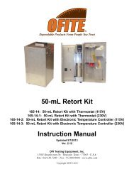
<strong>Atmospheric</strong> <strong>Consistometer</strong><br />
#120-75 (115V)<br />
#120-75-1 (220V)<br />
<strong>Instruction</strong> <strong>Manual</strong><br />
Updated 8/30/2013<br />
Ver. 2.3<br />
<strong>OFI</strong> <strong>Testing</strong> Equipment, Inc.<br />
11302 Steeplecrest Dr. · Houston, Texas · 77065 · U.S.A.<br />
Tele: 832.320.7300 · Fax: 713.880.9886 · www.ofite.com<br />
©<br />
Copyright <strong>OFI</strong>TE 2013
Table of<br />
Contents<br />
Intro....................................................................................................3<br />
Description........................................................................................3<br />
Features ............................................................................................3<br />
Requirements ...................................................................................3<br />
Components......................................................................................4<br />
Setup..................................................................................................6<br />
Loading the Test Cells.....................................................................7<br />
Operation ..........................................................................................8<br />
Calibration.........................................................................................9<br />
Maintenance....................................................................................11<br />
<strong>OFI</strong>TE, 11302 Steeplecrest Dr., Houston, TX 77065 USA / Tel: 832-320-7300 / Fax: 713-880-9886 / www.ofite.com 1
Intro<br />
The Model 60 <strong>Atmospheric</strong> <strong>Consistometer</strong> is designed to condition cement<br />
slurries as specified within API Specification 10. Determination of rheological<br />
properties, examination of free water content, and evaluation of the API<br />
fluid loss test all require that the cement slurry be conditioned by an atmospheric<br />
consistometer. The <strong>OFI</strong>TE Model 60 was specifically developed to<br />
perform these duties.<br />
Description<br />
A cement slurry is prepared according to the procedure outlined in the API<br />
Specification 10 and then placed in the slurry containers of the Model 60<br />
<strong>Atmospheric</strong> <strong>Consistometer</strong>. The slurry is stirred at 150 RPM by an APIdesigned<br />
paddle assembly. The temperature is controlled by a microprocessor,<br />
which displays the process temperature via a digital indicator.<br />
Consistency, measured in Bearden Units of Consistency, is determined by<br />
measuring the deflection of a calibrated spring. This deflection is created<br />
by the amount of torque that the cement slurry exerts on the paddle, which<br />
is a function of the consistency of the cement. The API defines 100 Bc as<br />
2,080 g-cm of torque.<br />
Features<br />
- Maximum operating temperature of 200°F<br />
- Unit is operated at atmospheric pressure<br />
- Temperature is maintained via a PID controller<br />
- Process temperature is displayed digitally<br />
- Heat transfer fluid is continuously circulated<br />
- Heater wattage is 1,500<br />
- Slurry container rotational speed is 150 rpm<br />
- Dual container design<br />
- Cooling system included<br />
- Stainless steel temperature bath<br />
- Deadweight calibration unit<br />
- Size: 24 × 16 × 18 inches (61 × 40.6 × 45.7 cm)<br />
- Weight: 95 lbs (43.1 kg)<br />
- Crated Size: 28 × 20 × 22 inches (71 × 50.8 × 55.9 cm)<br />
- Crated Weight: 160 lbs (72.6 kg)<br />
Requirements<br />
- Water Supply for Cooling<br />
- Water Drain<br />
- 220 Volt, 50/60 Hz, 2.2 KVA Power Source<br />
- 120 Volt, 50/60 Hz, 4.4 KVA Power Source<br />
<strong>OFI</strong>TE, 11302 Steeplecrest Dr., Houston, TX 77065 USA / Tel: 832-320-7300 / Fax: 713-880-9886 / www.ofite.com 2
#120-001 Mineral Oil, 1 Gallon, Qty: 3<br />
Components<br />
#120-75-8 Motor Timing Pulley<br />
#120-75-9 Weight Hanger<br />
#120-75-10 Slotted Weight Set<br />
#120-75-16 Calibration Stand<br />
#120-75-17 Driver Assembly<br />
#120-75-18 Potentiometer Assembly<br />
#120-75-19 Paddle Assembly<br />
#120-80-4 Temperature Controller<br />
#120-80-6 Motor<br />
#120-511 Slurry Cup Shear Pin<br />
#121-001 Container O-rings<br />
#121-002 Retaining Ring<br />
#121-007 Rotator Thrust Bearing<br />
#121-008 Thermocouple<br />
#121-009 Timing Belt<br />
#121-013 Slurry Container<br />
#121-014 Container Bottom<br />
#172-24 Solid State Relay<br />
#174-14 Motor Controller<br />
For 115 VAC Only:<br />
#120-76-003 Fuse, Main, 20 Amp, ¼" × 1¼"<br />
#120-76-002 Fuse, Heat, 15 Amp, ¼" × 1¼"<br />
#121-012 Fuse, Cool, 1 Amp, ¼" × 1¼"<br />
#172-07 Fuse, Motor, 5 Amp, ¼" × 1¼"<br />
#120-75-2 Water Solenoid Valve<br />
#121-010 Heater<br />
#152-37 AC Power Cord<br />
For 230 VAC Only:<br />
#172-09 Fuse, Main, 10 Amp, ¼" × 1¼"<br />
#121-016 Fuse, Heat, 7 Amp, ¼" × 1¼"<br />
#172-01 Fuse, Cool, ½ Amp, ¼" × 1¼"<br />
#120-76-001 Fuse, Motor, 3 Amp, ¼" × 1¼"<br />
#120-75-3 Water Solenoid Valve<br />
#121-010-1 Heater<br />
#152-38 AC Power Cord<br />
<strong>OFI</strong>TE, 11302 Steeplecrest Dr., Houston, TX 77065 USA / Tel: 832-320-7300 / Fax: 713-880-9886 / www.ofite.com 3
Optional:<br />
#120-76 Spare Parts for #120-75:<br />
#120-511 Slurry Cup Shear Pin, Qty: 10<br />
#120-602 Calibration Spring; Qty: 2<br />
#120-75-19 Paddle Assembly, Qty: 2<br />
#120-76-002 Fuse, Heat, 15 Amp, ¼" × 1¼", Qty: 4<br />
#120-76-003 Fuse, Main, 20 Amp, ¼" × ¼", Qty: 4<br />
#121-001 Container O-rings; Qty: 8<br />
#121-002 Retaining Ring; Qty: 2<br />
#121-005 Cap Nut<br />
#121-007 Rotator Thrust Bearing; Qty: 2<br />
#121-008 Thermocouple<br />
#121-009 Timing Belt; Qty: 2<br />
#121-010 Heater<br />
#121-012 Fuse, Cool, 1 Amp, ¼" × 1¼", Qty: 4<br />
#121-013 Slurry Container<br />
#121-014 Container Bottom; Qty: 2<br />
#172-07 Fuse, Motor, 5 Amp, ¼" × 1¼", Qty: 5<br />
#120-76-1 Spare Parts for #120-75-1:<br />
#120-511 Slurry Cup Shear Pin, Qty: 10<br />
#120-602 Calibration Spring; Qty: 2<br />
#120-75-19 Paddle Assembly, Qty: 2<br />
#120-76-001 Fuse, Motor, 3 Amp, ¼" × ¼", Qty: 4<br />
#121-001 Container O-rings; Qty: 8<br />
#121-002 Retaining Ring; Qty: 2<br />
#121-005 Cap Nut<br />
#121-007 Rotator Thrust Bearing; Qty: 2<br />
#121-008 Thermocouple<br />
#121-009 Timing Belt; Qty: 2<br />
#121-010-1 Heater<br />
#121-013 Slurry Container<br />
#121-014 Container Bottom; Qty: 2<br />
#121-016 Fuse, Heat, 7 Amp, ¼" × 1¼", Qty: 4<br />
#172-01 Fuse, Cool, ½ Amp, ¼" × 1¼", Qty: 4<br />
#172-09 Fuse, Main, 10 Amp, ¼" × 1¼", Qty: 5<br />
<strong>OFI</strong>TE, 11302 Steeplecrest Dr., Houston, TX 77065 USA / Tel: 832-320-7300 / Fax: 713-880-9886 / www.ofite.com 4
Setup<br />
1. Carefully remove the unit from the crate and place it close to a water<br />
supply and drain.<br />
Water supply and drain lines are ¼" tube connections and the water<br />
supply port should be connected to a 40 PSI (275.8 kPa) water source.<br />
The water drain is the port located near the middle of the lower back<br />
instrument panel.<br />
!<br />
Important<br />
2. Fill the bath with enough mineral oil to submerge the test cells at least<br />
half way.<br />
Do not overfill the bath.<br />
3. Connect the unit to a grounded and fused 10-amp electrical supply.<br />
4. The rotational speed of the unit may need to be adjusted periodically.<br />
a. Turn on the electrical power and start the motor.<br />
b. Measure the rotational speed of the rotators with a hand held<br />
tachometer. The rotational speed should be 150 RPM ± 15.<br />
c. If adjustment is required, loosen the three screws on the back panel<br />
of the unit and open the door. Directly to the right of the motor is<br />
the motor speed potentiometer.<br />
d. To increase the rotational speed, turn the speed control potentiometer<br />
clockwise. Turn it counter-clockwise to reduce the speed.<br />
Potentiometer<br />
<strong>OFI</strong>TE, 11302 Steeplecrest Dr., Houston, TX 77065 USA / Tel: 832-320-7300 / Fax: 713-880-9886 / www.ofite.com 5
Loading the<br />
Test Cells<br />
1. Prepare the cement slurry as specified in API Specification 10.<br />
2. Cover the paddle surface with a light coating of grease. This will facilitate<br />
cleaning after the test is complete.<br />
3. Pour the cement slurry into the test cell.<br />
4. Insert the paddle into the test cell. Make sure the point on the end of<br />
the paddle is inserted into the hole in the bottom of the test cell.<br />
5. Place the lid on the test cell by sliding the torque shaft over the end of<br />
the paddle. Turn the lid clockwise until the pin in the torque shaft<br />
engages with the slot in the paddle shaft.<br />
6. Continue turning the lid to lock it in place on top of the test cell.<br />
7. Lower the test cell into the bath and lock it in place with the locking<br />
pins.<br />
Torque Shaft<br />
Locking Pin<br />
Locking Pin<br />
Locking Pin<br />
<strong>OFI</strong>TE, 11302 Steeplecrest Dr., Houston, TX 77065 USA / Tel: 832-320-7300 / Fax: 713-880-9886 / www.ofite.com 6
Operation<br />
The <strong>OFI</strong>TE <strong>Atmospheric</strong> <strong>Consistometer</strong> performs two functions. It can be<br />
used to condition a cement slurry or to perform a thickening time test as<br />
detailed in API Specification 10.<br />
1. Turn the “Main” and “Heat” switches on.<br />
2. Set the appropriate temperature on the temperature controller.<br />
Actual Temperature<br />
Temperature Setpoint<br />
Set Temperature<br />
Temperature Controller<br />
!<br />
Important<br />
3. Load one or both test cells. Refer to “Setup - Loading the Test Cells”<br />
on page 6 for details.<br />
It is very important that you begin the test within one minute of<br />
mixing the cement slurry.<br />
4. Turn the “Motor” switch on.<br />
5. When the test or conditioning is complete, turn the “Heat” and “Motor”<br />
switches off and turn the “Cool” switch on.<br />
6. When the test cells are cool enough to touch, remove them from the<br />
unit and thoroughly clean them with soap and water. Be sure to<br />
remove any residual cement.<br />
<strong>OFI</strong>TE, 11302 Steeplecrest Dr., Houston, TX 77065 USA / Tel: 832-320-7300 / Fax: 713-880-9886 / www.ofite.com 7
Calibration<br />
Calibrating the torque head provides a reference point for interpreting test<br />
results. The calibration kit provided uses dead weight to simulate resistance<br />
on the torque head. To calibrate, four different weights are applied<br />
and the corresponding torque head readings are recorded. During operation,<br />
compare the torque head reading to those recorded during calibration<br />
to determine the amount of resistance being put on the torque head.<br />
Before calibrating the torque head, test the container paddle for excessive<br />
friction by running the sample container without any cement slurry in it. If<br />
the paddle is bent and rubbing on the side of the sample container or if the<br />
bearings are damaged, excessive friction will show on the dial (refer to the<br />
maintenance section on page 10 for more information). Correct any<br />
defects before calibrating the torque head.<br />
Calibration instructions are described in API-RP-10-B. Your instrument is<br />
equipped with an instrument-mounted calibration unit.<br />
1. Place the torque head onto the calibration stand.<br />
2. Place the calibration ring around the torque head.<br />
3. Wrap the deadweight calibration cord counter-clockwise around the<br />
calibration ring and over the roller.<br />
4. Place 400 g on the weight hanger and attach it to the calibration<br />
cord.<br />
Calibration Ring<br />
Torque Head<br />
Calibration Cord<br />
Hanger and Weight<br />
<strong>OFI</strong>TE, 11302 Steeplecrest Dr., Houston, TX 77065 USA / Tel: 832-320-7300 / Fax: 713-880-9886 / www.ofite.com 8
Note<br />
When adding weights, remember that the hook weighs 50 grams.<br />
Therefore, to test the potentiometer at 200g, you only need to add<br />
150g to the hook.<br />
5. Pull the weight down several times to obtain an average reading.<br />
6. Repeat this process with 100 g, 200 g, and 300 g. Record each<br />
weight and the corresponding reading. These values will help you<br />
interpret the potentiometer readings.<br />
<strong>OFI</strong>TE, 11302 Steeplecrest Dr., Houston, TX 77065 USA / Tel: 832-320-7300 / Fax: 713-880-9886 / www.ofite.com 9
Maintenance<br />
1. The belt and thrust bearings that drive the rotators should be inspected<br />
periodically. To disassemble the unit to access the bearings and belt:<br />
a. Disconnect the unit from all electrical power.<br />
b. Remove the back protective cover plate.<br />
c. Loosen the screws on the motor mount and push the motor forward.<br />
d. Release the belt from the motor timing sprocket.<br />
e. Remove the upper cover plate and set it on blocks or on a bucket to<br />
prevent damage to the agitator shaft.<br />
f. Loosen the four screws allowing the top plate to be removed from<br />
the bearing housing.<br />
g. Pull out the rotator and examine the thrust bearings for damage and<br />
wear. Periodically clean the bearings by lightly spraying them with<br />
WD-40. If they do not turn freely and smoothly, replace them with<br />
new bearings.<br />
h. Inspect the belt for damage or wear. If necessary, replace it with a<br />
new belt.<br />
i. Re-assemble the unit, pushing the belt through the bath slot.<br />
j. Pull the motor back only enough to prevent belt slippage. Allow<br />
approximately ¾" to 1" slack in the timing belt to prevent excessive<br />
side thrust to the bearings.<br />
Belt<br />
Bearing Agitator Shaft Rotator<br />
<strong>OFI</strong>TE, 11302 Steeplecrest Dr., Houston, TX 77065 USA / Tel: 832-320-7300 / Fax: 713-880-9886 / www.ofite.com 10
2. The bath should be checked and cleaned annually.<br />
a. Access the bath housing as described in steps a through f on the<br />
previous page.<br />
b. Visually inspect the mineral oil in the bath. If it contains any foriegn<br />
material, pour out the entire contents and refill with clean mineral oil.<br />
3. Containers and paddles should be kept as clean as possible. A light<br />
coating of grease on these components will facilitate cement removal.<br />
4. The unit has four fuses, located on the front panel beneath the four<br />
power switches. If any of the switches stop working, check the corresponding<br />
fuse. To remove a fuse, twist and pull the knob. After replacing<br />
the fuse, reinsert it into the slot and twist it to secure it in place.<br />
<strong>OFI</strong>TE, 11302 Steeplecrest Dr., Houston, TX 77065 USA / Tel: 832-320-7300 / Fax: 713-880-9886 / www.ofite.com 11