130-81 - Model 1100 Viscometer - OFI Testing Equipment, Inc.
130-81 - Model 1100 Viscometer - OFI Testing Equipment, Inc.
130-81 - Model 1100 Viscometer - OFI Testing Equipment, Inc.
Create successful ePaper yourself
Turn your PDF publications into a flip-book with our unique Google optimized e-Paper software.
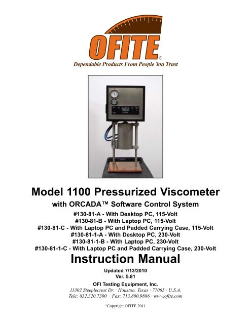
<strong>Model</strong> <strong>1100</strong> Pressurized <strong>Viscometer</strong><br />
with ORCADA Software Control System<br />
#<strong>130</strong>-<strong>81</strong>-A - With Desktop PC, 115-Volt<br />
#<strong>130</strong>-<strong>81</strong>-B - With Laptop PC, 115-Volt<br />
#<strong>130</strong>-<strong>81</strong>-C - With Laptop PC and Padded Carrying Case, 115-Volt<br />
#<strong>130</strong>-<strong>81</strong>-1-A - With Desktop PC, 230-Volt<br />
#<strong>130</strong>-<strong>81</strong>-1-B - With Laptop PC, 230-Volt<br />
#<strong>130</strong>-<strong>81</strong>-1-C - With Laptop PC and Padded Carrying Case, 230-Volt<br />
Instruction Manual<br />
Updated 7/13/2010<br />
Ver. 5.<strong>81</strong><br />
<strong>OFI</strong> <strong>Testing</strong> <strong>Equipment</strong>, <strong>Inc</strong>.<br />
1<strong>130</strong>2 Steeplecrest Dr. · Houston, Texas · 77065 · U.S.A.<br />
Tele: 832.320.7300 · Fax: 713.880.9886 · www.ofite.com<br />
©<br />
Copyright <strong>OFI</strong>TE 2011
Table of<br />
Contents<br />
Intro . . . . . . . . . . . . . . . . . . . . . . . . . . . . . . . . . . . . . . . . . . . . . . . . . .2<br />
Components . . . . . . . . . . . . . . . . . . . . . . . . . . . . . . . . . . . . . . . . . . .2<br />
Features . . . . . . . . . . . . . . . . . . . . . . . . . . . . . . . . . . . . . . . . . . . . . . .4<br />
Specifications . . . . . . . . . . . . . . . . . . . . . . . . . . . . . . . . . . . . . . . . . .5<br />
Setup . . . . . . . . . . . . . . . . . . . . . . . . . . . . . . . . . . . . . . . . . . . . . . . . .7<br />
Computer . . . . . . . . . . . . . . . . . . . . . . . . . . . . . . . . . . . . . . . . . . .7<br />
<strong>Viscometer</strong> . . . . . . . . . . . . . . . . . . . . . . . . . . . . . . . . . . . . . . . . . .8<br />
System Test . . . . . . . . . . . . . . . . . . . . . . . . . . . . . . . . . . . . . . . . . .9<br />
Preparing for a Test . . . . . . . . . . . . . . . . . . . . . . . . . . . . . . . . . . .11<br />
Software Start . . . . . . . . . . . . . . . . . . . . . . . . . . . . . . . . . . . . . . . . .12<br />
Calibration . . . . . . . . . . . . . . . . . . . . . . . . . . . . . . . . . . . . . . . . . . . .16<br />
Zeroing the Unit . . . . . . . . . . . . . . . . . . . . . . . . . . . . . . . . . . . . .19<br />
Fluid Manager . . . . . . . . . . . . . . . . . . . . . . . . . . . . . . . . . . . . . . .20<br />
Operation . . . . . . . . . . . . . . . . . . . . . . . . . . . . . . . . . . . . . . . . . . . . .21<br />
Manual Mode . . . . . . . . . . . . . . . . . . . . . . . . . . . . . . . . . . . . . . .21<br />
Auto Mode . . . . . . . . . . . . . . . . . . . . . . . . . . . . . . . . . . . . . . . . . .23<br />
Software . . . . . . . . . . . . . . . . . . . . . . . . . . . . . . . . . . . . . . . . . . . . . .24<br />
Options . . . . . . . . . . . . . . . . . . . . . . . . . . . . . . . . . . . . . . . . . . . .24<br />
Save Rate Settings . . . . . . . . . . . . . . . . . . . . . . . . . . . . . . . . . . .25<br />
Test Builder . . . . . . . . . . . . . . . . . . . . . . . . . . . . . . . . . . . . . . . . .26<br />
Select Analysis Outputs . . . . . . . . . . . . . . . . . . . . . . . . . . . . . . .29<br />
Saved Test Data . . . . . . . . . . . . . . . . . . . . . . . . . . . . . . . . . . . . .30<br />
Calibration History . . . . . . . . . . . . . . . . . . . . . . . . . . . . . . . . . . . .32<br />
Import/Export . . . . . . . . . . . . . . . . . . . . . . . . . . . . . . . . . . . . . . . .33<br />
Disassembly . . . . . . . . . . . . . . . . . . . . . . . . . . . . . . . . . . . . . . . . . .34<br />
Maintenance . . . . . . . . . . . . . . . . . . . . . . . . . . . . . . . . . . . . . . . . . .34<br />
Bob Shaft . . . . . . . . . . . . . . . . . . . . . . . . . . . . . . . . . . . . . . . . . .35<br />
Main Bearing Replacement . . . . . . . . . . . . . . . . . . . . . . . . . . . . .39<br />
Fuse Replacement . . . . . . . . . . . . . . . . . . . . . . . . . . . . . . . . . . .42<br />
Appendix . . . . . . . . . . . . . . . . . . . . . . . . . . . . . . . . . . . . . . . . . . . . .43<br />
Software Re-Installation . . . . . . . . . . . . . . . . . . . . . . . . . . . . . . .43<br />
Diagram . . . . . . . . . . . . . . . . . . . . . . . . . . . . . . . . . . . . . . . . . . . .44<br />
<strong>OFI</strong>TE, 1<strong>130</strong>2 Steeplecrest Dr., Houston, TX 77065 USA / Tel: 832-320-7300 / Fax: 713-880-9886 / www.ofite.com 1
Intro<br />
Components<br />
For enhanced data collection, <strong>OFI</strong>TE is pleased to introduce the new <strong>Model</strong><br />
<strong>1100</strong> Pressurized <strong>Viscometer</strong>. This fully-automated system accurately determines<br />
the flow characteristics of fracturing fluids and drilling fluids in terms of<br />
shear stress, shear rate, time, and temperature at pressure up to 1000 PSI.<br />
Using the exclusive ORCADA software, a computer novice can operate<br />
the <strong>Model</strong> <strong>1100</strong>, and yet the system is versatile enough for advanced<br />
research and demanding test parameters. The rugged <strong>Model</strong> <strong>1100</strong> is suitable<br />
for both field and laboratory use. An optional waterproof case with<br />
wheels makes the unit completely portable.<br />
#<strong>130</strong>-75-02 Cap O-ring; Qty: 2<br />
#<strong>130</strong>-75-04 Thermocouple O-ring; Qty: 2<br />
#<strong>130</strong>-75-14 O-ring<br />
#<strong>130</strong>-75-18 Transducer Cable Assembly<br />
#<strong>130</strong>-75-20 3/16" Spanner Wrench<br />
#<strong>130</strong>-75-21 R1B1 Tube / Fill<br />
#<strong>130</strong>-75-27 3/16" T-handle Allen Key<br />
#<strong>130</strong>-75-28 1/16" Allen Key<br />
#<strong>130</strong>-75-31 Motor Slide Nut<br />
#<strong>130</strong>-75-461 Coil Retainer<br />
#<strong>130</strong>-75-70 Waterproof Plastic Case with Casters<br />
#<strong>130</strong>-76-43 SSR<br />
#<strong>130</strong>-76-44 Thermocouple Jack<br />
#<strong>130</strong>-76-47 Retaining Ring Pliers; External<br />
#<strong>130</strong>-78-04 Sample Thermocouple<br />
#<strong>130</strong>-78-05 Main Seal<br />
#<strong>130</strong>-78-13 B1 Bob; Hastelloy with Threads for Stainless Steel<br />
#<strong>130</strong>-78-17 Bob Shaft Bearing; Qty: 4<br />
#<strong>130</strong>-78-18 Main Body Bearing, Sealed<br />
#<strong>130</strong>-78-20 Rotor Cup O-ring; 1¼" × 1½"; Viton V-14; Qty: 2<br />
#<strong>130</strong>-78-22 Stop Pin<br />
#<strong>130</strong>-78-25 Heater Bath Oil; 16 oz.<br />
#<strong>130</strong>-78-34 Packing Washer<br />
#<strong>130</strong>-78-36 O-ring; 13/16" × 1"; VIT-V75; Qty: 2<br />
#<strong>130</strong>-78-42 External Retaining Ring for Main Shaft<br />
#<strong>130</strong>-79-03 Laptop DAQ Card<br />
#<strong>130</strong>-79-07 DAQ Cable<br />
#<strong>130</strong>-79-15 Serial Cable; OB9; M/F<br />
#<strong>130</strong>-79-20 <strong>Model</strong> LF Controller; 525F; Limit Switch; 115V<br />
#<strong>130</strong>-79-21 <strong>Model</strong> LF Controller; 525F; Limit Switch; 230V<br />
#<strong>130</strong>-79-24 5-pin Female Connector<br />
#<strong>130</strong>-79-25 5-pin Female Connector<br />
#<strong>130</strong>-79-26 3-pin Female Connector<br />
#<strong>130</strong>-79-27 3-pin Female Connector<br />
#<strong>130</strong>-79-31 Control Card<br />
#<strong>130</strong>-<strong>81</strong>-001 O-ring; Qty: 2<br />
#<strong>130</strong>-<strong>81</strong>-002 Internal Pressure O-ring; Qty: 2<br />
#<strong>130</strong>-<strong>81</strong>-003 O-ring; Viton; Qty: 2<br />
#<strong>130</strong>-<strong>81</strong>-07 Valve Stem<br />
<strong>OFI</strong>TE, 1<strong>130</strong>2 Steeplecrest Dr., Houston, TX 77065 USA / Tel: 832-320-7300 / Fax: 713-880-9886 / www.ofite.com 2
#<strong>130</strong>-<strong>81</strong>-082 Torsion Spring; 1,000 Dyne/cm 2<br />
#<strong>130</strong>-<strong>81</strong>-084 Torsion Spring; 4,000 Dyne/cm 2<br />
#<strong>130</strong>-<strong>81</strong>-27 Socket Head Screw; ¼-28 × 1<br />
#<strong>130</strong>-<strong>81</strong>-35 Cable Chain; 25CCF-76-E<br />
#<strong>130</strong>-<strong>81</strong>-37 .050 Allen Key<br />
#<strong>130</strong>-<strong>81</strong>-38 Seal Nut Wrench<br />
#<strong>130</strong>-87-011 Stand Off; 4-40 × ½ × ¼<br />
#132-83 Calibration Fluid; 200 cP; 16 oz; Certified<br />
#152-38 AC Power Cord; 3-Conductor International (Continental<br />
European); Qty: 3<br />
#153-00 Bottle Brush<br />
#153-55 Silicone Stopcock Grease; Dow Corning; 150g Tube<br />
#153-67 60cc Disposable Syringe; Qty: 2<br />
#170-17 Valve Stem O-ring; Qty: 2<br />
#170-66 Adapter; 1/8" Tube × 1/8" Female Elbow<br />
#900-191 SS Swagelok Tube Fitting; Male Elbow; 1/8" Tube OD × ¼"<br />
Male NPT<br />
#900-194 SS Swagelok Tube Fitting; Union Cross; 1/8" Tube OD<br />
Optional:<br />
#<strong>130</strong>-78-13 B1 Bob; Hastelloy; with Threads for Stainless Steel<br />
#<strong>130</strong>-78-23 B1X Bob; 316 Stainless Steel<br />
#<strong>130</strong>-78-14 B2 Bob; Hastelloy<br />
#<strong>130</strong>-78-24-H B2X Bob; Hastelloy<br />
#<strong>130</strong>-78-15 B5 Bob; Hastelloy; with Threads for Stainless Steel<br />
#<strong>130</strong>-78-16 B5X Bob; Hastelloy; with Threads for Stainless Steel<br />
#132-80 100 cP Calibration Fluid; 16 oz.; Certified<br />
#132-82 500 cP Calibration Fluid; 16 oz.; Certified<br />
#152-55 Bath/Circulator; Caron <strong>Model</strong> 2050W; Refrigerated and<br />
Heated; 115V<br />
#152-55-1 Bath/Circulator; Caron <strong>Model</strong> 2050W; Refrigerated and<br />
Heated; 230V<br />
#165-44 High-Temperature Thread Lubricant; 1 oz Tube<br />
#<strong>130</strong>-<strong>81</strong>-SP Spare Parts for One Year for #<strong>130</strong>-<strong>81</strong>:<br />
#<strong>130</strong>-75-02 Cap O-ring; Qty: 4<br />
#<strong>130</strong>-75-04 O-ring for Thermocouple; Qty: 2<br />
#<strong>130</strong>-78-04 Sample Thermocouple; Qty: 2<br />
#<strong>130</strong>-78-05 Main Seal; Qty: 4<br />
#<strong>130</strong>-78-17 Bob Shaft Bearing; Qty: 24<br />
#<strong>130</strong>-78-18 Main Body Bearing; Sealed; Qty: 4<br />
#<strong>130</strong>-78-20 Rotor Cup O-ring; 1¼" × 1½"; Viton V-14; Qty: 4<br />
#<strong>130</strong>-78-25 Heater Bath Oil; 16 oz (480 mL); Qty: 8<br />
#<strong>130</strong>-78-34 Packing Washer<br />
#<strong>130</strong>-78-36 O-ring; 13/16" × 1"; Viton-V75<br />
#<strong>130</strong>-<strong>81</strong>-001 O-ring; Qty: 2<br />
#<strong>130</strong>-<strong>81</strong>-002 Internal Pressure O-ring; Qty: 2<br />
#<strong>130</strong>-<strong>81</strong>-003 Viton O-ring; Qty: 2<br />
#<strong>130</strong>-<strong>81</strong>-16 Bob Shaft Assembly<br />
#<strong>130</strong>-<strong>81</strong>-35 Cable Chain; 25CCF-76-E<br />
#135-04 External Retainer Ring; Qty: 12<br />
#170-17 Valve Stem O-ring; Qty: 6<br />
<strong>OFI</strong>TE, 1<strong>130</strong>2 Steeplecrest Dr., Houston, TX 77065 USA / Tel: 832-320-7300 / Fax: 713-880-9886 / www.ofite.com 3
Features<br />
- High Pressure - Up to 1,000 PSI (6,895 kPa).<br />
- High Temperature - Up to 500°F (260°C). An optional chiller (#152-55 /<br />
#152-55-1) can be used for testing to 32°F (0°C).<br />
- Low Motor Shear Rates - As low as 0.01s -1 .<br />
- Portable - The rugged carrying case is designed for field or laboratory<br />
use and is easy to transport.<br />
- Small Footprint - Only 12" x 12" (30 x 30 cm). The all-in-one design<br />
includes the heating mechanism.<br />
- Couette Geometry - Uses traditional Bobs and Rotor for measurements<br />
that are easy-to-translate (shear stress range 0-4000 dynes/cm 2 ).<br />
- Computer Controlled - Using the exclusive ORCADA software system,<br />
this viscometer is ideal for advanced research and demanding test<br />
parameters.<br />
- Data Acquisition - Store your data in a text format or in a Microsoft<br />
Excel file for easy access and reporting capabilities.<br />
<strong>OFI</strong>TE, 1<strong>130</strong>2 Steeplecrest Dr., Houston, TX 77065 USA / Tel: 832-320-7300 / Fax: 713-880-9886 / www.ofite.com 4
Specifications<br />
Instrument Geometry True Couette Coaxial Cylinder<br />
Motor Technology<br />
Stepper<br />
Motor Speeds (RPM) Variable Speed Range .01 - 600<br />
Speed Accuracy (RPM) .001<br />
Shear Rate Range (sec -1 ) .01 - 1,022<br />
Readout<br />
Computer Control and Data Acquisition<br />
Heat System<br />
Thermo Bath, 300 Watt, Max Temp 500°F<br />
(260°C)<br />
Cooling System<br />
Cold Water Circulation in Thermo Bath<br />
Temperature Measurement Type “J” Thermocouple<br />
Automatic Tests<br />
API Cementing, Mud and Fracture<br />
Rheology<br />
Power Requirements 115 or 230 Volts AC, 50/60 Hz<br />
Weight<br />
85 lbs (37.6 kg)<br />
Dimensions<br />
14" × 13" × 30" (36 × 33 × 76 cm)<br />
Shipping Weight<br />
150 lbs (68 kg)<br />
Computer Requipments<br />
DB-9 Serial Port, DAQ card and cable,<br />
Windows 2000 or XP.<br />
Range of Measurement for <strong>Model</strong> <strong>1100</strong><br />
Rotor - Bob R1B1 R1B2 R1B3 R1B4 R1B5<br />
Rotor Radius, RR (cm) 1.8415 1.8415 1.8415 1.8415 1.8415<br />
Bob Radius, RB (cm) 1.7245 1.2276 0.8622 0.8622 1.5987<br />
Bob Height, L (cm) 7.260 7.260 7.260 7.620 7.260<br />
Shear Gap (cm) 0.1170 0.6139 0.9793 0.9793 0.2428<br />
R Ratio, RB/RR 0.9365 0.666 0.4682 0.4682 0.8682<br />
Shear Rate Constant,<br />
KR, (sec -1 per RPM)<br />
1.7023 0.3770 0.2682 0.2682 0.8503<br />
Viscosity Conversions<br />
To convert from units on left side to units on top, multiply by factor @ intercept.<br />
from Centipoise Poise (P) g/(cm*s) (mN*s)m 2 mPa*s (lb*s)<br />
to (cP) 100 ft 2<br />
Centipoise 1 0.01 0.01 1 1 0.002088<br />
Poise (P) 100 1 1 100 100 0.2088<br />
g/(cm*s) 100 1 1 100 100 0.2088<br />
(mN*s)m 2 1 0.01 0.01 1 1 0.002088<br />
mPa*s 1 0.01 0.01 1 1 0.002088<br />
(lb*s) 478.93 4.789 4.789 478.93 478.93 1<br />
100 ft 2<br />
<strong>OFI</strong>TE, 1<strong>130</strong>2 Steeplecrest Dr., Houston, TX 77065 USA / Tel: 832-320-7300 / Fax: 713-880-9886 / www.ofite.com 5
Shear Stress Conversions<br />
To convert from units on left side to units on top, multiply by factor @ intercept.<br />
from Dyne/cm 2 Pa lb/100 ft 2 lb/ ft 2 DR<br />
to<br />
Dyne/cm 2 1 0.1 0.2084 0.002084 0.1957<br />
Pa 10 1 2.084 0.02084 1.957<br />
lb/100 ft 2 4.788 0.4788 1 0.01 0.939<br />
lb/ ft 2 478.8 47.88 100 1 93.9<br />
DR 5.107 0.5107 1.065 0.01065 1<br />
What Bob & Spring Should I Use?<br />
There is often confusion or misunderstanding about what a viscometer can<br />
actually measure. For example, a viscometer with a R1B1 F1 combination<br />
can measure water fairly well at 100 RPM and higher, but at 3 RPM, the<br />
readings would be shaky at best. While on the other hand, a linear fluid<br />
with a viscosity of 15000, could not get past 6 RPM with the same combination.<br />
To estimate which spring might be best, use the formula below to calculate<br />
a Minimum Spring factor, where one establishes the maximum RPM the<br />
fluid is going to be tested at, as well as what the expected “Apparent<br />
Viscosity” of the fluid would be at that RPM. If the Factor comes out as<br />
.87, then a F 1.0 spring should be used. If it comes out as .16, then a F<br />
0.2 spring would be best. To cover all ranges, it may be necessary to use<br />
more than one spring.<br />
Minimum Spring Factor (F) =<br />
RPM(max) * AV(max)<br />
BOB(F)*90000<br />
BOB (F)<br />
R1B1 1.0<br />
R1B2 8.9<br />
R1B3 25.4<br />
R1B4 50.7<br />
<strong>OFI</strong>TE, 1<strong>130</strong>2 Steeplecrest Dr., Houston, TX 77065 USA / Tel: 832-320-7300 / Fax: 713-880-9886 / www.ofite.com 6
Setup<br />
Computer<br />
1. First, check that the computer's AC power setting matches the available<br />
power in your region. This switch is typically found on the upper back<br />
panel of the computer and will be either 115V or 230V.<br />
2. Connect the monitor, mouse, and keyboard to the computer and connect<br />
the monitor and computer to an AC power outlet. The computer<br />
and monitor were shipped with the appropriate power cords.<br />
Note<br />
If your <strong>Model</strong> <strong>1100</strong> was supplied with a laptop computer instead of<br />
a desktop model, simply open the laptop and turn the power on.<br />
The AC power cord can be used to prevent the battery from draining<br />
completely during operation. Remember to periodically charge<br />
the battery by leaving the AC power cord plugged in overnight.<br />
3. Turn the monitor and computer on. After the computer has booted up<br />
completely, check for the ORCADA icon on the desktop.<br />
<strong>OFI</strong>TE, 1<strong>130</strong>2 Steeplecrest Dr., Houston, TX 77065 USA / Tel: 832-320-7300 / Fax: 713-880-9886 / www.ofite.com 7
Setup<br />
<strong>Viscometer</strong><br />
Note<br />
1. On the back panel, locate the three ¼" (6.35mm) NPT fittings. Connect<br />
a water source (15 - 30 PSI / 104 - 208 kPa), Nitrogen source, and<br />
drain hose to the appropriate fittings.<br />
The Nitrogen is used to pressurize the sample and prevent boiling at<br />
temperatures above 212°F (100°C). The water is used to cool the sample<br />
and raise and lower the bath. These connections are only necessary<br />
for tests exceeding 200°F (95°C).<br />
2. Connect the supplied water lines from the cabinet to the bath. The connections<br />
on the bath are ¼" NPT fittings. The connections on the cabinet<br />
are quick-connect fittings.<br />
3. Connect the supplied power cable from the cabinet to the bath.<br />
4. Plug the bath thermocouple into the designated port on the back panel<br />
of the cabinet.<br />
5. Connect the 9-pin RS232 cable to the serial ports on the viscometer<br />
and the computer.<br />
6. Connect the 68-pin DAQ cable to the corresponding ports on the viscometer<br />
and the computer. On the PC, this port will either be on the<br />
back (for desktops) or in the PCMCIA slot (for laptops).<br />
7. Make sure the “Power” switch is in the off position. Plug the power<br />
cord into an AC power source.<br />
Serial Port<br />
DAQ Port<br />
Air / Water Cool<br />
Thermocouple<br />
Main Power<br />
Power To Heaters<br />
Water To / From<br />
Bath<br />
<strong>OFI</strong>TE, 1<strong>130</strong>2 Steeplecrest Dr., Houston, TX 77065 USA / Tel: 832-320-7300 / Fax: 713-880-9886 / www.ofite.com 8
Setup<br />
System Test<br />
1. Turn the unit on. The power switch is located on the front panel.<br />
2. If the bath is in the raised position, lower it using the “Bath” switch.<br />
3. Notice that the sample cup is already attached to the viscometer. The<br />
sample cup is the Hastelloy cylindrical object hanging from the cabinet.<br />
The unit is packed and shipped this way to help protect the bob shaft.<br />
The bob shaft must be handled carefully; bending it will result in poor<br />
viscosity readings.<br />
<br />
Tip<br />
4. When the unit is on, the motor is engaged but not turning. To remove<br />
the sample cup, turn it clockwise until it clears the threads and then pull<br />
it straight down.<br />
If it is not convenient to have the unit powered on, use an Allen wrench<br />
or screw driver to hold the rotor in place while turning the sample cup.<br />
5. Carefully apply a thin coating of high-temperature thread lubricant<br />
(#165-44) to the bob shaft threads.<br />
Sample Cup<br />
Valve Stem<br />
Bath<br />
<strong>OFI</strong>TE, 1<strong>130</strong>2 Steeplecrest Dr., Houston, TX 77065 USA / Tel: 832-320-7300 / Fax: 713-880-9886 / www.ofite.com 9
6. Install the bob by sliding it onto the bob shaft with the tapered end<br />
down and screwing it securely into place. An R1B1 bob/rotor combination<br />
is standard for the <strong>Model</strong> <strong>1100</strong> <strong>Viscometer</strong>, however other combinations<br />
are available. See page 5 for more information.<br />
7. Turn on the computer and load the ORCADA software (see page 12<br />
for instructions).<br />
Rotor<br />
Bob<br />
Bath<br />
8. From the menu bar at the top of the screen, select “Utilities” and then<br />
“Calibrate Shear Stress”. Check the “Temperature” field to verify that it<br />
shows room temperature. Then, confirm that the value in the “Shear<br />
Stress Raw” fluctuates when you gently turn the bob with your hand.<br />
If either of these values does not display as expected, make sure the<br />
<strong>Model</strong> <strong>1100</strong> is turned on and that all cables are securely connected. If<br />
the problem is still not corrected, return to the “Main Screen” in the<br />
ORCADA software and choose “Edits” and then “Options”. In the<br />
“COM Port” drop-down menu, choose a different port and try again.<br />
See page 24 for information about the “Options” screen.<br />
9. It is recommended that a Calibration procedure be run due to the possibility<br />
of mishandling during shipment. Refer to the “Calibration” section<br />
on page 16 for detailed instructions on calibrating the unit.<br />
<strong>OFI</strong>TE, 1<strong>130</strong>2 Steeplecrest Dr., Houston, TX 77065 USA / Tel: 832-320-7300 / Fax: 713-880-9886 / www.ofite.com 10
Setup<br />
Preparing for a Test<br />
1. Install the bob as described in steps 1 - 6 on page 9.<br />
2. Fill the sample cup with the proper amount of fluid based on the bob<br />
you are using. Refer to the chart below.<br />
Bob Type Confirm B1 B2 B3 B4 B5 XB1 XB2 XB5<br />
Sample Amount in mL<br />
(R1 Sample Cup)<br />
42 78 96 104 52 32 73 44<br />
3. Hold the sample cup by hand and position the bob in the center. Push<br />
the sample cup up past the o-ring. Hold the sample cup in place and<br />
press the “Jog” switch on the front panel. The “Jog” switch will rotate<br />
the rotor at 60 RPM as long as it is held down. This will screw the<br />
sample cup into place on the rotor.<br />
Note<br />
The ORCADA Software must be open in order to use the “Jog<br />
Switch”.<br />
4. Fill the bath with approximately 80 mL of bath oil (#<strong>130</strong>-78-25).<br />
Periodically check the amount of oil inside the bath. The sample will<br />
take longer to heat if there is not enough oil in the bath.<br />
5. Raise the bath.<br />
6. To pressurize the sample, gradually rotate the regulator knob clockwise.<br />
To reduce pressure, gradually rotate the regulator knob counter-clockwise<br />
at a rate no greater than 60 PSI per minute.<br />
Note<br />
Pressure is only necessary for tests temperatures above 200°F (95°C).<br />
The heaters will be deactivated if the sample is not pressurized enough<br />
to prevent boiling. The ORCADA software will indicate this with a<br />
yellow alarm light. The alarm light will turn green when the appropriate<br />
pressure is applied to the sample. Refer to the chart below for the minimum<br />
pressure requirements.<br />
Temperature<br />
Pressure<br />
Ambient - 200°F (Ambient - 93.3°C) 0 PSI (0 kPa)<br />
201° - 295°F (93.9° - 146.1°C) 100 PSI (690 kPa)<br />
296° - 355°F (146.7° - 179.6°C) 200 PSI (1,380 kPa)<br />
356° - 395°F (180.1° - 201.8°C) 300 PSI (2,070 kPa)<br />
396° - 445°F (202.4° - 229.6°C) 500 PSI (3,450 kPa)<br />
446° - 500°F (230.2° - 260.2°C) 800 PSI (5,520 kPa)<br />
7. Once the pressure is set and the bath is in place, the <strong>Model</strong> <strong>1100</strong> is<br />
ready to run a test.<br />
<strong>OFI</strong>TE, 1<strong>130</strong>2 Steeplecrest Dr., Houston, TX 77065 USA / Tel: 832-320-7300 / Fax: 713-880-9886 / www.ofite.com 11
Software Start<br />
1. Double-click the “ORCADA” icon on the desktop.<br />
2. The first time you run the software, you will be asked to select a hardware<br />
configuration. Select “<strong>Model</strong> <strong>1100</strong>” and click “OK”. You will now<br />
see the Main Screen.<br />
3. The Windows XP firewall may try to block the ORCADA software<br />
from communicating with the viscometer. If the firewall shows the following<br />
alert, select “Unblock”.<br />
Windows XP Firewall Alert<br />
Available Tests<br />
Log Indicator<br />
Main Screen<br />
Status<br />
Communication<br />
Indicator<br />
Bath Control<br />
Key<br />
Manual Mode<br />
Controls<br />
Analysis Data<br />
Process Variables<br />
“Start Test” - This button starts a test in Auto Mode. Once a test is started,<br />
this button becomes the “Abort Test” button. Click here to stop the test.<br />
“Cement” - This button performs a standard cement test based on API<br />
specifications.<br />
“Mud” - This button performs a standard mud test based on API<br />
Specifications.<br />
<strong>OFI</strong>TE, 1<strong>130</strong>2 Steeplecrest Dr., Houston, TX 77065 USA / Tel: 832-320-7300 / Fax: 713-880-9886 / www.ofite.com 12
Note: The “Mud” and “Cement” tests ignore the “Dead Time” and “DAQ<br />
Time” settings on the Options screen. Temperature and pressure control,<br />
which are disabled during custom Auto-Mode tests, are available during a<br />
“Mud” or “Cement” test.<br />
“Progress” - This button opens the Test Progress window, which shows all<br />
of the steps of the current test and highlights the one currently in process.<br />
“Status” - This box at the top of the screen shows the current status of the<br />
test.<br />
“Comm Timeout” - This light will be off when the PC is successfully communicating<br />
with the viscometer. If communication is interrupted for any<br />
reason, the light will shine red to indicate a problem.<br />
“Start Logging” - This button is available in manual mode only. Click here<br />
to begin recording test data. The light next to this button will shine green<br />
while logging is in progress.<br />
“Cond Pause” - This button will pause a test during the conditioning phase<br />
and put the software into Manual Mode. While the test is paused, the<br />
motor and heat controls can be controlled in the same manner as in a standard<br />
Manual Mode test.<br />
To resume the test, click the “Cond Pause” button again. You will be asked<br />
if you want to “Continue” the test with the remaining conditioning time or if<br />
you want to “Override” the remaining time and extend the effective conditioning<br />
time. If you choose to “Continue”, the time remaining in the conditioning<br />
cycle will appear as though the test was never paused. If you<br />
choose to “Override”, the time remaining in the conditioning cycle will<br />
resume at the point where the test was paused.<br />
<strong>OFI</strong>TE, 1<strong>130</strong>2 Steeplecrest Dr., Houston, TX 77065 USA / Tel: 832-320-7300 / Fax: 713-880-9886 / www.ofite.com 13
For example, assume a test has a conditioning time of 10 minutes and the<br />
test is paused at the 5 minute mark for 1 minute. If the test is unpaused<br />
using the “Continue” option, the time remaining in the conditioning cycle will<br />
be 4 minutes. However, if the test is unpaused using the “Override” option,<br />
the time remaining in the conditioning cycle will be five minutes, making the<br />
effective total conditioning time 11 minutes.<br />
“Raw File Save Period” - This field determines how often data is recorded<br />
during a test.<br />
“Experiment Name” - This field will be used to identify the experiment<br />
later. This field is required before starting a test in Auto Mode or starting<br />
logging in Manual Mode.<br />
“Bob” - Select the type of bob currently being used in the unit. An incorrect<br />
value in this field will adversely affect your test results.<br />
“Key” - The checkboxes next to the graph key enable and disable graphing<br />
of the indicated values. For example, to exclude RPM from the graph,<br />
uncheck the “RPM” box. You can also customize the appearance of the<br />
lines on the graph by clicking on the line example on the right side of the<br />
key.<br />
“Manual Mode Controls” - The manual mode controls, in the bottom lefthand<br />
corner of the screen, adjust the rotor speed and the temperature<br />
while the unit is operating in manual mode.<br />
“Rotation” - This field determines the rotational speed. The drop-down<br />
box beneath the field set the units to either RPM or 1/s.<br />
“Enable” - Place a check in this box to engage the motor. Uncheck<br />
the box to stop the motor.<br />
“Temp” - This field determines the test temperature. The drop-down<br />
list beneath the field sets the units to either °F or °C.<br />
“Enable” - Place a check in this box to enable temperature control. If<br />
the value in the “Temp” field is higher than the sample temperature, the<br />
heaters will engage to heat the sample.<br />
“PreHeat” - The software will not heat a sample above 200°F (93°C)<br />
unless the sample is pressurized. The preheat button allows the software<br />
to heat the bath to higher temperatures without giving a low pressure<br />
warning. Enter a value in the "Temp" field and check the<br />
"PreHeat" box to preheat the bath prior to heating the sample.<br />
<strong>OFI</strong>TE, 1<strong>130</strong>2 Steeplecrest Dr., Houston, TX 77065 USA / Tel: 832-320-7300 / Fax: 713-880-9886 / www.ofite.com 14
“Cool” - Place a check in this box to activate the cooling solenoid and<br />
begin cooling the sample. The value in the “Temp” field must be lower<br />
than the sample for the software to initiate cooling.<br />
“Clear” - This button removes all data from the graph.<br />
“Analysis <strong>Model</strong>” - This field, below the graph, displays the current<br />
Analysis <strong>Model</strong> being used in the test. This variable is set in the Test<br />
Builder (refer to page 26 for more information).<br />
“Analysis Data” - This chart shows the calculated values based on the<br />
Analysis <strong>Model</strong> being used for the test. This data will not display until after<br />
the analysis sweep is completed.<br />
“Temperature”, “Shear Stress”, “Viscosity”, “Shear Rate”, “RPM” -<br />
These fields display the current value for these variables. They are display<br />
only. The drop-down box next to the “Shear Stress” field changes the units<br />
of the Shear Stress variable. The units can be set to: Dyne/cm 2 , lb/100ft 2 ,<br />
Pa., Dial Reading, lb/ft 2<br />
<strong>OFI</strong>TE, 1<strong>130</strong>2 Steeplecrest Dr., Houston, TX 77065 USA / Tel: 832-320-7300 / Fax: 713-880-9886 / www.ofite.com 15
Calibration<br />
The ORCADA calibration program should be run before performing the<br />
first test. Additional calibration is recommended when:<br />
1. The bob is changed.<br />
2. The unit has been sitting unused for several days.<br />
3. The unit has been serviced (i.e. bearings changed).<br />
4. If the “r^2” value displayed in the analysis model is below .92 during<br />
a sweep.<br />
5. Every two weeks during normal operation.<br />
The calibration fluid should be stored at room temperature and away from<br />
direct sunlight. The shelf life of the calibration fluid is 2 years. The calibration<br />
fluid used during the calibration program should be checked for suspended<br />
solids and clarity prior to being poured back into the bottle for storage.<br />
Cloudy calibration fluid should be disposed of properly.<br />
1. Prepare the viscometer for a test as described on page 8.<br />
2. Open the ORCADA software. From the menu bar select “Utilities”<br />
and then “Calibrate Shear Stress”.<br />
3. Observe the “Shear Stress Raw” value. Before performing any tests or<br />
calibrations, record this value (while the unit is at 0 RPM) here: ____ If<br />
this value drifts more than 2 or 3 units during the life of the machine,<br />
you must zero the transducer. Refer to 19 for instructions.<br />
4. Select a calibration fluid from the “Cal Fluid Batch” drop-down list. If<br />
the list is empty, click the “Fluid Manager” button to add new fluid<br />
batches. Refer to page 20 for instructions.<br />
!<br />
Important<br />
If the “Temp Out of Range” light shines red, the current sample temperature<br />
is out of the specified range for the calibration fluid. The sample<br />
will have to be heated or cooled to be within the acceptable range<br />
before calibration.<br />
Do not attempt a calibration if the sample is not within the appropriate<br />
temperature range.<br />
<strong>OFI</strong>TE, 1<strong>130</strong>2 Steeplecrest Dr., Houston, TX 77065 USA / Tel: 832-320-7300 / Fax: 713-880-9886 / www.ofite.com 16
5. Choose a set of calibration rates from the “Rate Set”<br />
drop-down list.<br />
To create or edit a rate set, click the “Calibration<br />
Rates” button. To create a new set, click the “New”<br />
button and enter a name and the rotational speeds.<br />
To edit a set, select it in the “Rate Set” list, then<br />
change the rotational speeds as necessary.<br />
Rate Sets<br />
6. Click the “Start Calibration” button to begin the calibration.<br />
Once the calibration has started, the software will begin filling in the<br />
chart and plotting the results on the graph.<br />
7. As the calibration proceeds, the software will begin to display the collected<br />
data in the chart. At the end of the calibration, the software will<br />
calculate the “r^2” value, which measures the accuracy of the calibration.<br />
If this value is less than 0.9990, recalibrate the unit. If this value<br />
is still low, change the bob shaft bearings (see page 35 for instructions)<br />
and try the calibration again. If the <strong>Model</strong> <strong>1100</strong> still does not calibrate,<br />
the unit will require servicing by an <strong>OFI</strong>TE technician.<br />
8. When the calibration is complete, check the r^2 value to make sure it is<br />
greater than .9990. If it is, click the “OK” button and enter a title for the<br />
calibration.<br />
<strong>OFI</strong>TE, 1<strong>130</strong>2 Steeplecrest Dr., Houston, TX 77065 USA / Tel: 832-320-7300 / Fax: 713-880-9886 / www.ofite.com 17
“S.S. Reference” - the shear stress as calculated by the software<br />
“S.S. Raw” - the actual signal coming from the unit<br />
“RPM” - rotational speed<br />
“Viscosity Reference” - the viscosity of the sample as calculated by the<br />
software<br />
“Temp” - the temperature of the sample<br />
“S.S. Best Fit” - shear stress value for a perfect calibration<br />
“Viscosity Best Fit” - viscosity value for a perfect calibration<br />
“S.S. Fit Error” - deviation of actual shear stress from “S.S. Best Fit”<br />
“r^2” - This is a measure of the accuracy of the calibration. It will be calculated<br />
at the end of the calibration cycle. If this value does not read<br />
greater than 0.9990 after multiple calibration tests, the unit will require<br />
servicing.<br />
“r^2C” - The r^2 value only provides useful information when a calibration<br />
is performed on a linear scale. For non-linear scales, the r^2C shows the<br />
corrected r^2 value and will provide a better measure of the accuracy of<br />
the calibration. For linear scales, the r^2 and r^2C values will be the<br />
same.<br />
“Temperature” - the temperature of the sample<br />
“Shear Rate” - rotational speed (1/s)<br />
“RPM” - rotational speed (RPM)<br />
“Shear Stress Raw” - the actual signal coming from the unit<br />
“Ref Viscosity” - the viscosity of the sample as calculated by the software<br />
“Ref Shear Stress” - the shear stress as calculated by the software<br />
<strong>OFI</strong>TE, 1<strong>130</strong>2 Steeplecrest Dr., Houston, TX 77065 USA / Tel: 832-320-7300 / Fax: 713-880-9886 / www.ofite.com 18
Calibration<br />
Zeroing the Unit<br />
When calibrating the <strong>Model</strong> <strong>1100</strong>, the “Shear Stress Raw” value on the calibration<br />
screen should display the value you recorded before the first calibration<br />
on page 16. If the signal reading is not within 2 or 3 units of this<br />
number, the transducer will need to be reset to zero.<br />
To zero the unit for calibration you must adjust the position of the transducer<br />
cap.<br />
1. Bleed off all pressure from the system. Remove the top panel by loosening<br />
the four quarter-turn locks on each corner.<br />
!<br />
Important<br />
2. Loosen, but do not remove, the thermocouple compression fitting from<br />
the top of the transducer cap.<br />
Be very careful to keep the thermocouple straight. A bent thermocouple<br />
will cause inaccurate readings.<br />
3. Loosen the eight set screws with the 1/16" (1.59 mm) Allen wrench provided.<br />
4. Observer the “Shear Stress Raw” value on the “Calibrate Shear Stress”<br />
screen in the ORCADA software.<br />
5. Slowly rotate the transducer cap until the “Shear Stress Raw” value<br />
reaches the desired range. The sensor is very sensitive, so only very<br />
slight adjustments are required. Allow a few seconds for the signal to<br />
stabilize between adjustments.<br />
6. Once the signal is within range, tighten the setscrews on the transducer<br />
cap. Observe the signal value after 15 seconds to make sure the signal<br />
does not drift out of range.<br />
7. Tighten the thermocouple compression fitting.<br />
Thermocouple<br />
Compression<br />
Fitting<br />
Transducer Cap<br />
Set Screw<br />
<strong>OFI</strong>TE, 1<strong>130</strong>2 Steeplecrest Dr., Houston, TX 77065 USA / Tel: 832-320-7300 / Fax: 713-880-9886 / www.ofite.com 19
Calibration<br />
Fluid Manager<br />
Before calibrating the unit, you must input the specifications of the calibration<br />
fluid that you are using. This will give the software the information it<br />
needs to perform the calibration accurately.<br />
Click the “Fluid Manager” button on the Calibration screen to add a new<br />
calibration fluid batch.<br />
1. Click “New” to add a new batch. You can also edit an existing batch<br />
by selecting it in the “Batch Selector” list.<br />
2. In the “Batch” field, type a name for the batch. <strong>OFI</strong>TE recommends<br />
using the lot number and viscosity from the Certification Chart that<br />
was provided with the fluid.<br />
3. In the “Calibration Fluid Table”, enter at least two<br />
Temperature/Viscosity pairs from the Certification Chart. Only two<br />
pairs are required.<br />
The “Table Linearity Error” light will shine red if the values in the<br />
“Calibration Fluid Table” do not create a straight line. If this occurs,<br />
check the values and re-enter them.<br />
4. Once you have entered all the batches, click “OK” to close the Fluid<br />
Manager and return to the Calibration screen.<br />
<strong>OFI</strong>TE, 1<strong>130</strong>2 Steeplecrest Dr., Houston, TX 77065 USA / Tel: 832-320-7300 / Fax: 713-880-9886 / www.ofite.com 20
Operation<br />
Manual Mode<br />
To begin a test in Manual mode:<br />
1. Prepare the viscometer for a test. Refer to page 8 for instructions.<br />
2. Choose the shear stress units from the drop-down box next to the<br />
“Shear Stress” field. Your choices are: Dyne/cm 2 , lb/100ft 2 , Pa., Dial<br />
Readings, and lb/ft 2 .<br />
3. Enter a value in the “Rotation” field and choose a setting for units<br />
(RPM or 1/s).<br />
4. Select the “Enable” checkbox next to the “Rotation” field to start the<br />
motor.<br />
Note<br />
Once the motor is started, the display fields on the right-hand side<br />
of the screen will begin displaying test data.<br />
5. Enter a temperature in the “Temp” field and choose Celsius or<br />
Fahrenheit.<br />
6. Select the “Enable” checkbox next to the “Temp” field to start the<br />
heater.<br />
Note<br />
!<br />
Important<br />
Here, checking the “Enable” and “PreHeat” button allows you to preheat<br />
the bath to the desired temperature without applying any initial<br />
heat to the sample. When the bath has reached the temperature set<br />
point, raise the bath to begin heating the sample.<br />
Remember, if your test will exceed 200°F (93°C), apply the recommended<br />
pressure based on the chart on page 11.<br />
7. Enter a name in the “Experiment Name” field and click the “Start<br />
Logging” button.<br />
This field will be used to identify the experiment later.<br />
8. Enter a comment in the resulting dialog box. Comments are optional,<br />
but can be used later to identify the test results.<br />
9. To stop the test, click the “Stop Logging” button and uncheck the<br />
“Enable” checkboxes.<br />
<strong>OFI</strong>TE, 1<strong>130</strong>2 Steeplecrest Dr., Houston, TX 77065 USA / Tel: 832-320-7300 / Fax: 713-880-9886 / www.ofite.com 21
10. Check the “Cool” box to allow the water supply to enter the bath<br />
cooling element and cool the sample.<br />
!<br />
Important<br />
11. Disassemble and clean the unit (refer to page 34 for instructions).<br />
Allow the sample temperature to drop below 120°F (49°C)<br />
before reducing the pressure. Make sure the pressure reads 0<br />
before removing the sample cup.<br />
<strong>OFI</strong>TE, 1<strong>130</strong>2 Steeplecrest Dr., Houston, TX 77065 USA / Tel: 832-320-7300 / Fax: 713-880-9886 / www.ofite.com 22
Operation<br />
Auto Mode<br />
<br />
Tip<br />
To begin a test in Auto mode:<br />
1. Prepare the viscometer for a test. Refer to page 8 for instructions.<br />
2. Choose a test to run from the list in the upper left-hand corner of<br />
the Main Screen.<br />
If no tests are listed, create a new one in the “Test Builder”. Refer<br />
to page 26 for instructions.<br />
3. Enter a name in the “Experiment Name” field.<br />
4. Set the shear stress units using the drop-down menu next to the<br />
“Shear Stress” field.<br />
5. Click the “Start Test” button.<br />
6. Enter a comment in the resulting dialog box. Comments are optional,<br />
but can be used later to identify the test results.<br />
7. When the test is complete, check the “Cool” box to allow the water<br />
supply to enter the bath cooling element and cool the sample.<br />
!<br />
Important<br />
8. Disassemble and clean the unit (refer to page 34 for instructions).<br />
Allow the sample temperature to drop below 120°F (49°C)<br />
before reducing the pressure. Make sure the pressure reads 0<br />
before removing the sample cup.<br />
<strong>OFI</strong>TE, 1<strong>130</strong>2 Steeplecrest Dr., Houston, TX 77065 USA / Tel: 832-320-7300 / Fax: 713-880-9886 / www.ofite.com 23
Software<br />
Options<br />
To access the Options screen, choose “Options” from the “Edit” menu.<br />
“Enable Bath Level Control” - If this box is checked, the “Raise Bath” button<br />
on the “Main Screen” will be visible and active.<br />
“RPM DAQ Settings” - “RPM High”, “RPM Med” and “RPM Low”, “Dead<br />
Time”, “DAQ Time”. These fields are used to determine the amount of time<br />
needed for the sample to stabilize at a given rate. The fields are also used<br />
to determine the amount of time data is averaged before being saved. For<br />
example, if RPM High is set to 60, Dead Time is set to 15 and DAQ Time is<br />
set to 20, any rate of 60 RPM or greater during a sweep would stabilize for<br />
15 seconds then begin averaging data for 20 seconds before saving the<br />
data.<br />
“Reverse Rates Gel UI” - If “Hystoresis” is selected on the “Test Builder”<br />
screen (see page 26), this option will perform a gel test after the forward<br />
portion of the sweep and after the backward portion.<br />
“Slave ID” - If multiple units are being monitored through the ORCADA<br />
Software, each one must be identified by a unique “Slave ID”.<br />
“Device Number” - see Slave ID<br />
“Data Archive Directory” - Specify the directory to store archived data.<br />
<strong>OFI</strong>TE, 1<strong>130</strong>2 Steeplecrest Dr., Houston, TX 77065 USA / Tel: 832-320-7300 / Fax: 713-880-9886 / www.ofite.com 24
Software<br />
Save Rate Settings<br />
By default, the ORCADA Software saves data to file based on a set time<br />
interval. This time interval can be changed by editing the “Raw File Save<br />
Period” field on the main screen. However, the “Save Rate Settings” feature<br />
provides more control over data save points. The software will monitor<br />
each selected variable and record a data point to the file when that variable<br />
changes by the amount specified.<br />
1. Select “Save Rate Settings” from the “Edit” menu.<br />
2. Place a check mark next to each variable you wish to monitor.<br />
3. In the field after the variable name, enter the variance required to initiate<br />
a save point.<br />
For example, if you want the software to record a data point when the<br />
temperature increases or decreases more than 5°, place a check next<br />
to “Temperature” and enter 5 in the field next to it.<br />
4. Click “OK” to save the settings and return to the main screen.<br />
“Elapsed Time” - seconds since the start of the test<br />
“RPM” - rotational speed (RPM)<br />
“Shear Rate” - rotational speed (1/s)<br />
“RPM SP” - rotational speed setpoint<br />
“Temperature” - measured sample temperature<br />
“Temperature Bath” - measured temperature of the oil bath<br />
“Temperature pH” - Not available on the <strong>Model</strong> <strong>1100</strong>.<br />
“Temp SP” - temperature setpoint<br />
“Temp Duty Cycle” - the frequency (in seconds) the<br />
heaters engage to increase the temperature<br />
“Viscosity” - measured viscosity (cP)<br />
“Shear Stress” - measured shear stress<br />
“Shear Stress Tare” - change in measured shear stress<br />
“Pressure” - measured pressure<br />
“Pressure SP” - pressure setpoint<br />
“pH” - Not available on the <strong>Model</strong> <strong>1100</strong>.<br />
<strong>OFI</strong>TE, 1<strong>130</strong>2 Steeplecrest Dr., Houston, TX 77065 USA / Tel: 832-320-7300 / Fax: 713-880-9886 / www.ofite.com 25
Software<br />
Test Builder<br />
The Test Builder is designed to help you build custom tests for use in Auto<br />
mode. To access the test builder, go to the Main Screen and choose “Test<br />
Builder” from the “Edit” menu.<br />
1. To create a new test, click the “New Test” button. To create a new<br />
test based on one of the “RP 10B”, “RP 13D”, or “RP 39” analysis<br />
models, click the appropriate button at the top of the screen to open<br />
a template. To edit an existing test, select the test from the list in<br />
the upper left-hand corner of the screen.<br />
2. Enter a name in the “Test Name” field.<br />
3. Choose an Analysis <strong>Model</strong>.<br />
a. “RP 39” - Power Law <strong>Model</strong> - records the Power Law calculations<br />
(n and k)<br />
b. “RP 13D” - Bingham Plastic Analysis <strong>Model</strong>s - records plastic<br />
viscosity (PV) and yield point (YP)<br />
c. “RP 10B” - Power Law and Bingham Plastic <strong>Model</strong>s combined<br />
4. Input the values for your test into the fields in Record 1.<br />
a. “Heat Time” - the time it will take the unit to heat the sample to<br />
the temperature setpoint. If this field is left blank, the unit will<br />
heat the sample as fast as possible.<br />
b. “Heat RPM” - the rotational speed during the heating period<br />
c. “Temp” - the temperature setpoint. Enter any letter in this field<br />
to indicate “Ambient”.<br />
Available Tests<br />
Records<br />
Test Detail<br />
<strong>OFI</strong>TE, 1<strong>130</strong>2 Steeplecrest Dr., Houston, TX 77065 USA / Tel: 832-320-7300 / Fax: 713-880-9886 / www.ofite.com 26
d. “Cond. Time” - the time period to condition the sample<br />
e. “Cond. RPM” - the rotational speed during conditioning<br />
f. “#/Swps” - the number of sweeps to perform after conditioning.<br />
A sweep is a set of rotational speeds separated by time interval.<br />
Between sweeps, the rotor returns to the Cond. RPM. At the<br />
end of each sweep, the unit calculates the Analysis <strong>Model</strong> values.<br />
g. “Delta Time” - the time interval between sweeps<br />
h. “Gel Time 1” - During a gel time interval, the rotor comes to a<br />
complete stop and waits. At the end of the interval, the rotational<br />
speed is increased to 3 RPM until the gel breaks and a gel<br />
strength value is recorded. Click the “Insert Gel Column” button<br />
to add a gel time to the record.<br />
i. “RPM 1, 2, 3” - The RPM fields set the speed of each step of<br />
the sweep.<br />
5. Click the “OK” button to save the test and return to the main screen.<br />
“Hold for Temp” - Click this checkbox to tell the unit to wait until the sample<br />
has reached the temperature setpoint before proceeding to the next<br />
step. If this box is unchecked, the test will proceed while the sample is<br />
heating.<br />
“Temp Threshold” - This field specifies an acceptable variance on the<br />
temperature. For example, if the temperature setpoint is 150° and the<br />
“Temp Threshold” is set to 5°, the unit will consider the setpoint reached<br />
when the temperature is between 145° and 155°.<br />
“Temp Unit” - set temperature units to either °F or °C<br />
“Rate Unit” - set the rate units to either RPM or 1/s<br />
“Pressure Unit” - set the pressure units to either PSI or kPa<br />
“Hystoresis” - If this box is checked, each sweep will be performed forward<br />
and backwards.<br />
“Stir Parameters” - These parameters only apply if the test includes a gel<br />
time.<br />
“Stir Prior to Gel” - Check this box to stir the sample before calculating<br />
gel strength.<br />
<strong>OFI</strong>TE, 1<strong>130</strong>2 Steeplecrest Dr., Houston, TX 77065 USA / Tel: 832-320-7300 / Fax: 713-880-9886 / www.ofite.com 27
“Gel Stir Rate” - This is the rate the sample will be stirred prior to calculating<br />
gel strength.<br />
“Gel Stir Time” - This is the time interval the sample will be stirred.<br />
“Plot All Records” - If this box is checked, all records will be plotted on<br />
the graph. If it is not checked, only the currently highlighted record will be<br />
plotted.<br />
The graph below the records provides a visual representation of the current<br />
test. Each line represents one aspect of the test: RPM Setpoint,<br />
Temperature Setpoint, Pressure Setpoint, and Temperature PV. Refer to<br />
the key to the right of the graph for details.<br />
The graph features a cursor, a vertical yellow line, that can be used to view<br />
more detailed information about the different phases of the test. The<br />
“Center Cursor” button moves the cursor to the center of the graph. Click<br />
and drag the cursor across the graph to see more detailed information.<br />
Refer to the “Test Detail” field below the graph for more information.<br />
<strong>OFI</strong>TE, 1<strong>130</strong>2 Steeplecrest Dr., Houston, TX 77065 USA / Tel: 832-320-7300 / Fax: 713-880-9886 / www.ofite.com 28
Software<br />
Select Analysis<br />
Outputs<br />
After building a test in the Test Builder, the chart at the bottom of the Main<br />
Screen will show the various data points being calculated by the viscometer<br />
based on the chosen Analysis <strong>Model</strong>. This chart, however, is customizable.<br />
You can choose which data points are displayed on the chart and which<br />
are not.<br />
From the “Edit” menu, choose “Select Analysis Outputs”. By default, all<br />
data points are selected and will appear on the chart. To remove a data<br />
point from the chart, simply uncheck the box next to it.<br />
<strong>OFI</strong>TE, 1<strong>130</strong>2 Steeplecrest Dr., Houston, TX 77065 USA / Tel: 832-320-7300 / Fax: 713-880-9886 / www.ofite.com 29
Software<br />
Saved Test Data<br />
To review test data from past tests:<br />
1. Select “Saved Test Data” from the “File” menu.<br />
2. The saved test data is grouped by month. Select the folder for the year<br />
and month of the data you are looking for and click the small + sign<br />
next to it. This will show you all of the data for tests run that month,<br />
including any comments you added.<br />
3. Select the test you are looking for and click the “OK” button. Multiple<br />
tests can be selected by holding down the CTRL key and selecting<br />
each test.<br />
Saved Experiment Explorer<br />
4. On the “Raw Data” tab you will see the graph of the test results. The<br />
“Analyzed Data” tab shows the results of the calculations based on the<br />
Analysis <strong>Model</strong>. The “Test Setup” tab shows the parameters of the test.<br />
Raw Data<br />
<strong>OFI</strong>TE, 1<strong>130</strong>2 Steeplecrest Dr., Houston, TX 77065 USA / Tel: 832-320-7300 / Fax: 713-880-9886 / www.ofite.com 30
“Export” - Click this button if you wish to export the test data to a file. You<br />
will be asked to select a filename and destination and then click “OK”. The<br />
resulting file can then be opened in Microsoft ® Excel for further analysis.<br />
“Print” - Click this button to print the results to the default printer.<br />
“Experiment Explorer” - Click this button to choose another set of test<br />
data to review.<br />
“OK” - Click this button to return to the main screen.<br />
Analysed Data<br />
Test Setup<br />
<strong>OFI</strong>TE, 1<strong>130</strong>2 Steeplecrest Dr., Houston, TX 77065 USA / Tel: 832-320-7300 / Fax: 713-880-9886 / www.ofite.com 31
Software<br />
Calibration History<br />
On the Calibration History Screen, you can retrieve the data from all past<br />
calibration tests.<br />
1. Begin on the Main Screen. Select “Calibration History” from the<br />
“Utilities” menu.<br />
2. The calibration tests are grouped by month. Select the folder for the<br />
year and month of the calibration test you are looking for and click the<br />
small + sign next to it. This will show you all of the calibration tests run<br />
that month, including the fluid batch and any comments you added after<br />
the test.<br />
3. Select the test you wish to view and click the “OK” button.<br />
4. You can now see the graph, chart, and fluid batch details.<br />
5. Click the “Export” button if you wish to export the calibration results to a<br />
file. You will be asked to select a filename and destination and then<br />
click “OK”.<br />
6. When you are finished reviewing the calibration history, click the “OK”<br />
button to return to the main screen.<br />
Calibration History Explorer<br />
Calibration History<br />
<strong>OFI</strong>TE, 1<strong>130</strong>2 Steeplecrest Dr., Houston, TX 77065 USA / Tel: 832-320-7300 / Fax: 713-880-9886 / www.ofite.com 32
Software<br />
Import/Export<br />
The Import/Export feature of the ORCADA Software makes it possible to<br />
transfer a test from one PC to another.<br />
1. Begin on the Main Screen. Choose “Export” from the “File” menu.<br />
2. Select the tests you wish to export. Hold down the CTRL key to select<br />
multiple tests.<br />
3. Click the “Export” button. You will be asked to choose a destination<br />
and filename and then click “OK”.<br />
4. Copy this file to the destination PC.<br />
The file must be placed in the correct folder for it to be available for<br />
import. To find this folder, first navigate to the folder specified in the<br />
“Data Archive Directory” field in the Options screen (see page 24 for<br />
details). From there go to the “ORCADA” folder and then the “Tests<br />
Import Export” folder.<br />
5. On the destination PC, choose “Import” from the “File” menu.<br />
6. Choose the tests you wish to import. Hold down the CTRL key to<br />
select multiple tests.<br />
The “Export” field lists all of the files that are available for import. Once<br />
you have selected one, the “Tests” field shows which individual tests<br />
can be imported from that file.<br />
Below the “Export” and “Tests” fields is a display-only field that shows<br />
the folder being scanned for exported tests. Make sure the tests you<br />
want to import have been placed in that folder.<br />
7. Click the “Import” button. The new tests will appear in the list in the<br />
upper left-hand corner of the Main Screen.<br />
Export<br />
Import<br />
<strong>OFI</strong>TE, 1<strong>130</strong>2 Steeplecrest Dr., Houston, TX 77065 USA / Tel: 832-320-7300 / Fax: 713-880-9886 / www.ofite.com 33
Disassembly<br />
This procedure should be performed immediately after every test.<br />
1. Lower the bath.<br />
2. Allow sample to cool to below 120°F (48.9°C).<br />
3. Gradually decrease the pressure at a rate of 30 - 60 PSI (200 - 400<br />
kPa) per minute.<br />
4. Slowly open the valve stem at the bottom of the sample cup (see photo<br />
on page 9). This will relieve any remaining pressure from the cup.<br />
Keep a container underneath the valve stem to collect any sample fluid<br />
that leaks.<br />
5. Turn the sample cup clockwise until it is free from the rotor. Pull the<br />
sample cup straight down and position it directly under the bob to catch<br />
any residual fluid that may be dripping.<br />
6. Gently turn the bob counter-clockwise to remove it from the bob shaft.<br />
!<br />
Important<br />
Maintenance<br />
7. Clean all removed parts with water and/or appropriate solvent. Wipe<br />
any residual fluid from inside the rotor with a folded paper towel. Be<br />
careful not to hit the bob shaft.<br />
It is important to remove the bob from the bob shaft while transporting<br />
the viscometer to prevent bending or damaging the bob shaft<br />
assembly.<br />
Before performing any type of maintenance, be sure and unplug the power<br />
supply and bleed off all Nitrogen. Also, be careful not to bend the bob<br />
shaft.<br />
When working with bearings, be careful not to handle them with your bare<br />
hands. The oil from your skin can contaminate the bearing.<br />
A good indicator that maintenance is required is if the r^2 value is less than<br />
.9990 (refer to page 18 for more information). If a calibration check using<br />
certified calibration fluid shows viscosity readings that are not linear at multiple<br />
shear rates, this can also indicate a problem that requires maintenance.<br />
<strong>OFI</strong>TE, 1<strong>130</strong>2 Steeplecrest Dr., Houston, TX 77065 USA / Tel: 832-320-7300 / Fax: 713-880-9886 / www.ofite.com 34
Maintenance<br />
Bob Shaft<br />
1. Unplug the viscometer from the electrical source. Shut off the Nitrogen<br />
supply and bleed off all pressure.<br />
2. Remove the bob from the bob shaft.<br />
3. Remove the top panel.<br />
4. Unplug the thermocouple and the grey cable that runs into the top of<br />
the transducer cap.<br />
!<br />
Important<br />
5. Loosen, but do not remove, the thermocouple compression fitting from<br />
the top of the torsion cap (¼ turn counter-clockwise). Pull the thermocouple<br />
straight up to remove it.<br />
Be very careful to keep the thermocouple straight. A bent thermocouple<br />
will cause inaccurate readings.<br />
6. Unscrew the eight Allen bolts from the transducer cap. Be careful not<br />
to drop the Allen bolts into the viscometer. Remove the transducer cap<br />
and set it aside.<br />
7. Unscrew the eight Allen bolts that hold the transducer body to the main<br />
body. Remove the transducer body. It may be necessary to loosen the<br />
o-ring seal by gently rocking the transducer body back and forth.<br />
Thermocouple<br />
Compression<br />
Fitting<br />
Transducer<br />
Cap<br />
Thermocouple<br />
Wire<br />
8. Loosen the set screw on the torsion spring.<br />
9. With the split ring pliers, remove the retaining ring just below the bearing<br />
retainer.<br />
<strong>OFI</strong>TE, 1<strong>130</strong>2 Steeplecrest Dr., Houston, TX 77065 USA / Tel: 832-320-7300 / Fax: 713-880-9886 / www.ofite.com 35
10. Slide the lower bearing and bearing retainer off the bob shaft.<br />
Bob Shaft<br />
Lower Bob<br />
Shaft Bearing<br />
Retaining Ring<br />
Transducer Body<br />
11. Pull the bob shaft up and out of the transducer body.<br />
12. At this point, the torsion spring is fully accessible in case it needs to be<br />
changed. To change the torsion spring:<br />
a. Turn the transducer body upside down.<br />
b. Unscrew the hex screws on the spring retainer.<br />
c. Remove the spring retainer and torsion spring.<br />
d. Insert a new torsion spring into the depression in the transducer body.<br />
e. Slide the spring retainer over the torsion spring and secure it in<br />
place with the hex screws.<br />
Spring Retainer<br />
Set Screw<br />
Torsion Spring<br />
Transducer Body<br />
<strong>OFI</strong>TE, 1<strong>130</strong>2 Steeplecrest Dr., Houston, TX 77065 USA / Tel: 832-320-7300 / Fax: 713-880-9886 / www.ofite.com 36
13. Slide the upper bearing off the bob shaft.<br />
!<br />
Important<br />
14. Slide a new bearing onto the bob shaft.<br />
Do not touch the new bearings with your bare hands. Oils from<br />
your skin can damage it.<br />
15. Slide the bob shaft back into the transducer body.<br />
16. Slide a new bearing onto the bottom of the bob shaft. Slide a bearing<br />
retainer onto the shaft beneath the bearing.<br />
17. Using the split ring pliers, place the retaining ring below the bearing<br />
retainer to hold it in place.<br />
18. With the transducer body upside down, turn the bob shaft clockwise<br />
until it stops. Then turn the bob shaft back slightly and tighten the set<br />
screw on the torsion spring to secure it to the bob shaft.<br />
19. Inspect the o-ring on the torsion body and replace it if necessary. Apply<br />
a light coat of silicone grease around the o-ring.<br />
20. Lower transducer body back into the main body.<br />
Make sure the stop pin on the head of the bob shaft is aligned toward<br />
the front of the viscometer.<br />
Transducer Body<br />
Stop Pin<br />
21. Lubricate the Allen bolt threads with a thin coating of high-temperature<br />
thread lubricant (#165-44). Screw the eight Allen bolts back into place<br />
on the transducer body. Tighten the bolts in a criss-cross pattern.<br />
22. Place the transducer cap back on top of the transducer body.<br />
<strong>OFI</strong>TE, 1<strong>130</strong>2 Steeplecrest Dr., Houston, TX 77065 USA / Tel: 832-320-7300 / Fax: 713-880-9886 / www.ofite.com 37
23. Lubricate the Allen bolt threads with a thin coating of high-temperature<br />
thread lubricant (#165-44). Screw the eight Allen bolts back into place<br />
on the transducer cap. Tighten the bolts in a criss-cross pattern.<br />
24. Place the thermocouple back into the transducer cap and hand-tighten<br />
the thermocouple compression fitting.<br />
25. Plug in the thermocouple and transducer.<br />
26. Turn the unit on.<br />
27. Re-calibrate the unit before performing another test.<br />
<strong>OFI</strong>TE, 1<strong>130</strong>2 Steeplecrest Dr., Houston, TX 77065 USA / Tel: 832-320-7300 / Fax: 713-880-9886 / www.ofite.com 38
Maintenance<br />
Main Bearing<br />
Replacement<br />
1. Remove the bob shaft assembly as described in steps 1 - 10 on page 35.<br />
2. Loosen the Allen bolts at the bottom of the motor. Slide the motor forward<br />
just enough to loosen the belt and remove it from the rotor.<br />
Head Assembly<br />
Head Assembly<br />
Allen Bolts<br />
3. Remove the spiral retaining ring with the supplied pliers. Pull the rotor<br />
assembly straight down to remove it from the main body.<br />
!<br />
Important<br />
4. Remove the main bearing from the main body and replace it with a new<br />
one.<br />
Do not touch the new bearings with your bare hands. Oils from<br />
your skin can damage it.<br />
Main Body<br />
Spiral Retaining<br />
Ring<br />
Main Bearing<br />
<strong>OFI</strong>TE, 1<strong>130</strong>2 Steeplecrest Dr., Houston, TX 77065 USA / Tel: 832-320-7300 / Fax: 713-880-9886 / www.ofite.com 39
5. With the supplied spanner wrench, remove the brass seal nut from<br />
beneath the main body.<br />
Lower Bearing<br />
Main Body<br />
Seal Nut<br />
6. The main seal is seated inside the top of the seal nut. Inspect this seal<br />
and replace it if it shows signs of damage or wear.<br />
7. The lower bearing sits inside the bottom of the seal nut. Inspect this<br />
bearing and replace it if it shows signs of damage or wear.<br />
!<br />
Important<br />
The main bearing is pressed into the seal nut and cannot be removed<br />
without destroying it. Do not attempt to remove the main bearing<br />
unless it is already damaged and not usable.<br />
Do not touch the new bearings with your bare hands. Oils from<br />
your skin can damage it.<br />
Lower Bearing<br />
Main Seal<br />
Seal Nut<br />
<strong>OFI</strong>TE, 1<strong>130</strong>2 Steeplecrest Dr., Houston, TX 77065 USA / Tel: 832-320-7300 / Fax: 713-880-9886 / www.ofite.com 40
8. Once the bearings and seals have been replaced, screw the seal nut<br />
back into the main body. Use the spanner wrench to tighten it.<br />
9. Insert the rotor back into the main body from below.<br />
10. Wrap the chain around the rotor and pull the motor back to tighten it.<br />
Tighten the Allen bolts on the motor to secure it in place.<br />
11. Place the spiral retaining ring around the shaft to hold it in place.<br />
12. Reassemble the head assembly as described in step 14 - 26 on page 35.<br />
<strong>OFI</strong>TE, 1<strong>130</strong>2 Steeplecrest Dr., Houston, TX 77065 USA / Tel: 832-320-7300 / Fax: 713-880-9886 / www.ofite.com 41
Maintenance<br />
Fuse Replacement<br />
There are two fuses that control the power supply. They are located in a<br />
small compartment by the power switch. Simply use a small screwdriver to<br />
pry open the compartment and replace as needed. Use two 6-amp fuses<br />
for 115 volt units and two 3-amp fuses for 230 volt units.<br />
Additional fuses are located inside the cabinet. To replace these fuses:<br />
1. Open the back cabinet by loosening the two quarter-turn locks.<br />
2. You will see 6 fuses on the inside of the back panel. The black fuses<br />
pop out and the gray ones flip up.<br />
F3<br />
F2<br />
F1<br />
F6<br />
F5<br />
F4<br />
Label Component Fuse (115V) Fuse (230V)<br />
F1 Heater 4 amp 2 amp<br />
F2 Motor 4 amp 2 amp<br />
F3 Main Power Supply 2 amp 1 amp<br />
F4 SSR - Heater 6 amp 3 amp<br />
F5 SSR - Cooling 6 amp 3 amp<br />
F6 SSR - Ram 6 amp 3 amp<br />
<strong>OFI</strong>TE, 1<strong>130</strong>2 Steeplecrest Dr., Houston, TX 77065 USA / Tel: 832-320-7300 / Fax: 713-880-9886 / www.ofite.com 42
Appendix<br />
Software Re-<br />
Installation<br />
This section outlines the steps necessary to re-install the <strong>Model</strong> <strong>1100</strong> and<br />
data acquisition software packages. This will only be necessary in the case<br />
of computer replacement or catastrophic failure in the current computer<br />
system.<br />
1. You must physically remove the DAQ card from the computer's PCI<br />
slot<br />
2. Turn on the computer and place the NI-DAQ CD in the drive and<br />
wait for it to start up. When ready, install the NI-DAQ software. If<br />
the software asks you for the “device” being installed, it is “PCI<br />
6024E”.<br />
3. When the install program stops and asks you if you want to reboot<br />
the machine, or shut down manually, choose to shut down manually.<br />
Do not remove the CD.<br />
4. Shut down the computer, and re-install the DAQ card.<br />
5. Start up the machine again, and you should see the computer find<br />
the card and load drivers for it. The install package will start up<br />
again and finish the install.<br />
6. This step takes you eventually to the point where you will set up the<br />
channels. Start up the DAQ program. The program is called<br />
“Measurement and Automation”. Under the “Configuration” window,<br />
you will see a tree structure. Under “My System”, open the<br />
“Devices and Interfaces” node. You should see a device listed as<br />
DAQ-6020E (Device 1), right-click on this and select “properties”.<br />
Within the “System” tab, select “Test Resources”. This should<br />
respond that the device has passed the test.<br />
7. Next, right-click on the “Data Neighborhood” node under “My<br />
System”. Select the “Create New...” option. Select “Virtual Channel”<br />
and click the finish button. This begins the dialog of creating a new<br />
channel. You will create 4 Analog Input channels, 1 Analog Output<br />
channel and 1 Digital IO channel.<br />
8. Place the <strong>OFI</strong>TE ORCADA <strong>Model</strong> <strong>1100</strong> Software CD or startup<br />
floppy into the appropriate drive.<br />
9. Double click “Setup.exe” and follow the on-screen instructions.<br />
You are now ready to run the software.<br />
<strong>OFI</strong>TE, 1<strong>130</strong>2 Steeplecrest Dr., Houston, TX 77065 USA / Tel: 832-320-7300 / Fax: 713-880-9886 / www.ofite.com 43
Appendix<br />
Diagram<br />
Refer to the next page for a list of parts that correspond to the labels on<br />
this diagram.<br />
<strong>OFI</strong>TE, 1<strong>130</strong>2 Steeplecrest Dr., Houston, TX 77065 USA / Tel: 832-320-7300 / Fax: 713-880-9886 / www.ofite.com 44
The parts listed below correspond to the labels on the diagram on the previous<br />
page.<br />
# <strong>OFI</strong>TE Part # Description<br />
1 <strong>130</strong>-<strong>81</strong>-12 Main Body<br />
2 <strong>130</strong>-78-36 O-ring; Viton; #117<br />
3 <strong>130</strong>-<strong>81</strong>-001 O-ring; Viton; #029<br />
4 <strong>130</strong>-<strong>81</strong>-22 Lower Bearing<br />
5 <strong>130</strong>-<strong>81</strong>-21 Seal Nut<br />
6 <strong>130</strong>-78-05 Main Seal<br />
7 <strong>130</strong>-<strong>81</strong>-27 Hex Socket Head Cap Screw; ¼-28 × 1"<br />
8 <strong>130</strong>-<strong>81</strong>-04 Retaining Ring; Spiral<br />
9 <strong>130</strong>-78-18 Main Bearing<br />
10 <strong>130</strong>-<strong>81</strong>-14 Rotor Tube<br />
11 <strong>130</strong>-78-42 Spiral Retaining Ring<br />
12 <strong>130</strong>-78-30H Expansion Joint; C276<br />
13 <strong>130</strong>-78-34 Packing Washer<br />
14 <strong>130</strong>-78-20 Rotor Cup O-ring; Viton; #218<br />
15 <strong>130</strong>-<strong>81</strong>-05 Guard Washer<br />
16 <strong>130</strong>-75-02 Cap O-ring; Viton; #036<br />
17 <strong>130</strong>-<strong>81</strong>-15 Transducer Body<br />
18 <strong>130</strong>-75-75 Standoff<br />
19 <strong>130</strong>-<strong>81</strong>-082 Torsion Spring; 1,000 Dyne/cm 2<br />
20 <strong>130</strong>-78-22 1/16" × 3/8" Stop Pin<br />
21 <strong>130</strong>-78-17 Bob Shaft Bearing<br />
22 <strong>130</strong>-<strong>81</strong>-11 Guide Tube<br />
23 <strong>130</strong>-75-46 Sensor Retainer<br />
24 <strong>130</strong>-75-79 Hex Socket Head Cap Screw; 8-32<br />
25 <strong>130</strong>-75-78 Hex Socket Flat Head Cap Screw; 8-32<br />
26 135-05 Bushing<br />
27 <strong>130</strong>-<strong>81</strong>-19 Bearing Retainer<br />
28 <strong>130</strong>-78-07 B1 Bob<br />
29 <strong>130</strong>-77-069 Nitrogen Port; SS Swagelok Tube Fitting; Male<br />
Connector; 1/8" Tube OD × 1/8" Male NPT<br />
30 <strong>130</strong>-<strong>81</strong>-160 Bob Shaft Assembly<br />
31 <strong>130</strong>-<strong>81</strong>-18 Transducer Clamp<br />
32 <strong>130</strong>-<strong>81</strong>-02 Transducer<br />
33 <strong>130</strong>-75-76 Sensor Retainer Set Screw; #6-32 × .125<br />
34 <strong>130</strong>-<strong>81</strong>-007 Thermocouple Compression Fitting; SS-1-UT-1-2BT<br />
35 Hex Socket Head Cap Screw; ¼-28 UNF - 1<br />
36 <strong>130</strong>-<strong>81</strong>-17 Transducer Cap<br />
37 <strong>130</strong>-<strong>81</strong>-002 O-ring; Viton; #034<br />
38 Hex Socket Head Cap Screw; 5/16-24 UNF - 1<br />
39 <strong>130</strong>-<strong>81</strong>-060 R1 Rotor Assembly<br />
<strong>OFI</strong>TE, 1<strong>130</strong>2 Steeplecrest Dr., Houston, TX 77065 USA / Tel: 832-320-7300 / Fax: 713-880-9886 / www.ofite.com 45


