Industrial Computing Solutions Fan-less Computer NISE ... - Omtec
Industrial Computing Solutions Fan-less Computer NISE ... - Omtec
Industrial Computing Solutions Fan-less Computer NISE ... - Omtec

Create successful ePaper yourself
Turn your PDF publications into a flip-book with our unique Google optimized e-Paper software.
NEXCOM International Co., Ltd.<br />
<strong>Industrial</strong> <strong>Computing</strong> <strong>Solutions</strong><br />
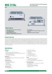
<strong>Fan</strong>-<strong>less</strong> <strong>Computer</strong><br />
<strong>NISE</strong> 2100, <strong>NISE</strong> 2100A, <strong>NISE</strong> 2110, <strong>NISE</strong> 2110A<br />
User Manual<br />
NEXCOM International Co., Ltd.<br />
Published January 2011<br />
www.nexcom.com
Contents<br />
Contents<br />
Preface<br />
Copyright .............................................................................................. iv<br />
Disclaimer .............................................................................................. iv<br />
Acknowledgements ............................................................................... iv<br />
Regulatory Compliance Statements ....................................................... iv<br />
Declaration of Conformity...................................................................... iv<br />
RoHS Compliance.................................................................................... v<br />
Warranty and RMA................................................................................. vi<br />
Safety Information .................................................................................vii<br />
Installation Recommendations................................................................vii<br />
Safety Precautions.................................................................................viii<br />
Technical Support and Assistance............................................................ ix<br />
Conventions Used in this Manual............................................................ ix<br />
Global Service Contact Information......................................................... x<br />
Package Contents...................................................................................xii<br />
Ordering Information.............................................................................xiii<br />
Chapter 1: Product Introduction<br />
Overview.................................................................................................1<br />
<strong>NISE</strong> 2100/2100A..................................................................................1<br />
<strong>NISE</strong> 2110/2110A..................................................................................2<br />
Hardware Specifications..........................................................................3<br />
Getting to Know <strong>NISE</strong> 2100/2110 Series..................................................5<br />
Mechanical Dimensions...........................................................................9<br />
Chapter 2: Jumpers And Connectors<br />
Before You Begin...................................................................................13<br />
Precautions............................................................................................13<br />
Jumper Settings.....................................................................................14<br />
Locations of the Jumpers and Connectors..............................................15<br />
Jumpers..............................................................................................17<br />
Clear CMOS......................................................................................17<br />
COM3 RS232 RI Pin Power Select......................................................17<br />
Panel CCFL LVDS Backlight Power Select...........................................18<br />
Connector Pin Definitions....................................................................19<br />
External I/O Interface - Front Panel....................................................19<br />
USB Ports........................................................................................19<br />
COM5 Serial Port............................................................................19<br />
COM6 Serial Port............................................................................20<br />
GPIO Connector.............................................................................20<br />
Status Indicators.............................................................................21<br />
ATX Power On/Off Switch...............................................................21<br />
External I/O Interface - Rear Panel.....................................................22<br />
9-36V DC Input..............................................................................22<br />
Remote Power On/Off Switch.........................................................22<br />
VGA Port........................................................................................23<br />
Speaker-out Jack.............................................................................23<br />
LAN1 and LAN2 Ports.....................................................................24<br />
LAN3 (<strong>NISE</strong> 2100/2110 only) and Dual USB Ports............................25<br />
Copyright © 2011 NEXCOM International Co., Ltd. All Rights Reserved. ii <strong>NISE</strong> 2100, <strong>NISE</strong> 2100A, <strong>NISE</strong> 2110, <strong>NISE</strong> 2110A User Manual
Contents<br />
COM1 and COM2 Ports..................................................................26<br />
COM3 and COM4 Ports..................................................................27<br />
USB 8-9 Connector.........................................................................27<br />
Internal Connectors..........................................................................28<br />
COM5 Connector...........................................................................28<br />
COM6 Connector...........................................................................28<br />
Remote Power On/Off Switch.........................................................29<br />
CPU <strong>Fan</strong> Connector........................................................................29<br />
Internal Power/HDD/LAN Power/LAN Active LED (RTC Connector)...30<br />
SMBus Pin Header..........................................................................30<br />
Mic-in Connector............................................................................31<br />
Power Output Connector................................................................31<br />
LVDS Connector.............................................................................32<br />
Panel CCFL Connector....................................................................32<br />
CompactFlash.................................................................................33<br />
Mini-PCIe Slot.................................................................................34<br />
PCI Slot (Low Profile).......................................................................35<br />
Chapter 3: System Setup<br />
Removing the Chassis Cover .................................................................36<br />
Installing a SODIMM..............................................................................37<br />
Installing a Wire<strong>less</strong> LAN Module...........................................................39<br />
Installing a SATA Hard Drive (<strong>NISE</strong> 2100/2100A)....................................41<br />
Installing a SATA Hard Drive (<strong>NISE</strong> 2110/2110A)....................................44<br />
Installing a SATA DOM...........................................................................48<br />
Installing a CompactFlash Card..............................................................49<br />
Entering Setup.......................................................................................53<br />
Legends.................................................................................................53<br />
BIOS Setup Utility..................................................................................54<br />
Main...................................................................................................54<br />
Advanced............................................................................................55<br />
Boot....................................................................................................61<br />
Chipset...............................................................................................63<br />
PCIPnP................................................................................................66<br />
Security...............................................................................................67<br />
Exit.....................................................................................................68<br />
Appendix A: Power Consumption<br />
Test Configuration.................................................................................69<br />
Power Consumption Measurement........................................................70<br />
Appendix B: GPI/O Programming Guide<br />
J8 - GPI/O Connector.............................................................................71<br />
GPI/O Programming Sample Code.........................................................71<br />
Appendix C: Watchdog Timer Setting<br />
Watchdog Timer Setting........................................................................73<br />
ITE8783 WatchDog Programming Guide................................................74<br />
Chapter 4: BIOS Setup<br />
About BIOS Setup..................................................................................52<br />
When to Configure the BIOS.................................................................52<br />
Default Configuration............................................................................53<br />
Copyright © 2011 NEXCOM International Co., Ltd. All Rights Reserved.<br />
iii<br />
<strong>NISE</strong> 2100, <strong>NISE</strong> 2100A, <strong>NISE</strong> 2110, <strong>NISE</strong> 2110A User Manual
Preface<br />
Preface<br />
Copyright<br />
This publication, including all photographs, illustrations and software, is<br />
protected under international copyright laws, with all rights reserved. No<br />
part of this manual may be reproduced, copied, translated or transmitted<br />
in any form or by any means without the prior written consent from<br />
NEXCOM International Co., Ltd.<br />
Disclaimer<br />
The information in this document is subject to change without prior notice<br />
and does not represent commitment from NEXCOM International Co., Ltd.<br />
However, users may update their knowledge of any product in use by constantly<br />
checking its manual posted on our website: http://www.nexcom.<br />
com. NEXCOM shall not be liable for direct, indirect, special, incidental, or<br />
consequential damages arising out of the use of any product, nor for any<br />
infringements upon the rights of third parties, which may result from such<br />
use. Any implied warranties of merchantability or fitness for any particular<br />
purpose is also disclaimed.<br />
Acknowledgements<br />
<strong>NISE</strong> 2100/2110 Series is a trademark of NEXCOM International Co., Ltd.<br />
All other product names mentioned herein are registered trademarks of<br />
their respective owners.<br />
Regulatory Compliance Statements<br />
This section provides the FCC compliance statement for Class A devices<br />
and describes how to keep the system CE compliant.<br />
Declaration of Conformity<br />
FCC<br />
This equipment has been tested and verified to comply with the limits for<br />
a Class A digital device, pursuant to Part 15 of FCC Rules. These limits are<br />
designed to provide reasonable protection against harmful interference<br />
when the equipment is operated in a commercial environment. This equipment<br />
generates, uses, and can radiate radio frequency energy and, if not<br />
installed and used in accordance with the instructions, may cause harmful<br />
interference to radio communications. Operation of this equipment in a<br />
residential area (domestic environment) is likely to cause harmful interference,<br />
in which case the user will be required to correct the interference<br />
(take adequate measures) at their own expense.<br />
CE<br />
The product(s) described in this manual complies with all applicable European<br />
Union (CE) directives if it has a CE marking. For computer systems to<br />
remain CE compliant, only CE-compliant parts may be used. Maintaining<br />
CE compliance also requires proper cable and cabling techniques.<br />
Copyright © 2011 NEXCOM International Co., Ltd. All Rights Reserved. iv <strong>NISE</strong> 2100, <strong>NISE</strong> 2100A, <strong>NISE</strong> 2110, <strong>NISE</strong> 2110A User Manual
Preface<br />
RoHS Compliance<br />
NEXCOM RoHS Environmental Policy and Status<br />
Update<br />
NEXCOM is a global citizen for building the digital infrastructure.<br />
We are committed to providing green products<br />
and services, which are compliant with European Union<br />
RoHS (Restriction on Use of Hazardous Substance in Electronic Equipment)<br />
directive 2002/95/EU, to be your trusted green partner and to protect our<br />
environment.<br />
RoHS restricts the use of Lead (Pb) < 0.1% or 1,000ppm, Mercury (Hg)<br />
< 0.1% or 1,000ppm, Cadmium (Cd) < 0.01% or 100ppm, Hexavalent<br />
Chromium (Cr6+) < 0.1% or 1,000ppm, Polybrominated biphenyls (PBB) <<br />
0.1% or 1,000ppm, and Polybrominated diphenyl Ethers (PBDE) < 0.1% or<br />
1,000ppm.<br />
In order to meet the RoHS compliant directives, NEXCOM has established an<br />
engineering and manufacturing task force in to implement the introduction<br />
of green products. The task force will ensure that we follow the standard<br />
NEXCOM development procedure and that all the new RoHS components<br />
and new manufacturing processes maintain the highest industry quality<br />
levels for which NEXCOM are renowned.<br />
The model selection criteria will be based on market demand. Vendors and<br />
suppliers will ensure that all designed components will be RoHS compliant.<br />
How to recognize NEXCOM RoHS Products?<br />
For existing products where there are non-RoHS and RoHS versions, the suffix<br />
“(LF)” will be added to the compliant product name.<br />
All new product models launched after January 2006 will be RoHS compliant.<br />
They will use the usual NEXCOM naming convention.<br />
Copyright © 2011 NEXCOM International Co., Ltd. All Rights Reserved. v <strong>NISE</strong> 2100, <strong>NISE</strong> 2100A, <strong>NISE</strong> 2110, <strong>NISE</strong> 2110A User Manual
Preface<br />
Warranty and RMA<br />
NEXCOM Warranty Period<br />
NEXCOM manufactures products that are new or equivalent to new in<br />
accordance with industry standard. NEXCOM warrants that products will<br />
be free from defect in material and workmanship for 2 years, beginning<br />
on the date of invoice by NEXCOM. HCP series products (Blade Server)<br />
which are manufactured by NEXCOM are covered by a three year warranty<br />
period.<br />
NEXCOM Return Merchandise Authorization (RMA)<br />
??<br />
Customers shall enclose the “NEXCOM RMA Service Form” with the<br />
returned packages.<br />
??<br />
Customers must collect all the information about the problems encountered<br />
and note anything abnormal or, print out any on-screen messages,<br />
and describe the problems on the “NEXCOM RMA Service Form” for<br />
the RMA number apply process.<br />
??<br />
Customers can send back the faulty products with or without accessories<br />
(manuals, cable, etc.) and any components from the card, such as<br />
CPU and RAM. If the components were suspected as part of the problems,<br />
please note clearly which components are included. Otherwise,<br />
NEXCOM is not responsible for the devices/parts.<br />
??<br />
Customers are responsible for the safe packaging of defective products,<br />
making sure it is durable enough to be resistant against further damage<br />
and deterioration during transportation. In case of damages occurred<br />
during transportation, the repair is treated as “Out of Warranty.”<br />
??<br />
Any products returned by NEXCOM to other locations besides the customers’<br />
site will bear an extra charge and will be billed to the customer.<br />
Repair Service Charges for Out-of-Warranty Products<br />
NEXCOM will charge for out-of-warranty products in two categories, one<br />
is basic diagnostic fee and another is component (product) fee.<br />
System Level<br />
??<br />
Component fee: NEXCOM will only charge for main components such<br />
as SMD chip, BGA chip, etc. Passive components will be repaired for<br />
free, ex: resistor, capacitor.<br />
??<br />
Items will be replaced with NEXCOM products if the original one cannot<br />
be repaired. Ex: motherboard, power supply, etc.<br />
??<br />
Replace with 3rd party products if needed.<br />
??<br />
If RMA goods can not be repaired, NEXCOM will return it to the customer<br />
without any charge.<br />
Board Level<br />
??<br />
Component fee: NEXCOM will only charge for main components, such<br />
as SMD chip, BGA chip, etc. Passive components will be repaired for<br />
free, ex: resistors, capacitors.<br />
? ? If RMA goods can not be repaired, NEXCOM will return it to the customer<br />
without any charge.<br />
Copyright © 2011 NEXCOM International Co., Ltd. All Rights Reserved. vi <strong>NISE</strong> 2100, <strong>NISE</strong> 2100A, <strong>NISE</strong> 2110, <strong>NISE</strong> 2110A User Manual
Preface<br />
Warnings<br />
Read and adhere to all warnings, cautions, and notices in this guide and<br />
the documentation supplied with the chassis, power supply, and accessory<br />
modules. If the instructions for the chassis and power supply are inconsistent<br />
with these instructions or the instructions for accessory modules,<br />
contact the supplier to find out how you can ensure that your computer<br />
meets safety and regulatory requirements.<br />
Cautions<br />
Electrostatic discharge (ESD) can damage system components. Do the described<br />
procedures only at an ESD workstation. If no such station is available,<br />
you can provide some ESD protection by wearing an antistatic wrist<br />
strap and attaching it to a metal part of the computer chassis.<br />
Safety Information<br />
Before installing and using the device, note the following precautions:<br />
▪▪<br />
Read all instructions carefully.<br />
▪▪<br />
Do not place the unit on an unstable surface, cart, or stand.<br />
▪▪<br />
Follow all warnings and cautions in this manual.<br />
▪▪<br />
When replacing parts, ensure that your service technician uses parts<br />
specified by the manufacturer.<br />
▪▪<br />
Avoid using the system near water, in direct sunlight, or near a heating<br />
device.<br />
▪▪<br />
The load of the system unit does not solely rely for support from the<br />
rackmounts located on the sides. Firm support from the bottom is highly<br />
necessary in order to provide balance stability.<br />
▪▪<br />
The computer is provided with a battery-powered real-time clock circuit.<br />
There is a danger of explosion if battery is incorrectly replaced. Replace<br />
only with the same or equivalent type recommended by the manufacturer.<br />
Discard used batteries according to the manufacturer’s instructions.<br />
Installation Recommendations<br />
Ensure you have a stable, clean working environment. Dust and dirt can<br />
get into components and cause a malfunction. Use containers to keep<br />
small components separated.<br />
Adequate lighting and proper tools can prevent you from accidentally<br />
damaging the internal components. Most of the procedures that follow<br />
require only a few simple tools, including the following:<br />
• A Philips screwdriver<br />
• A flat-tipped screwdriver<br />
• A grounding strap<br />
• An anti-static pad<br />
Using your fingers can disconnect most of the connections. It is recommended<br />
that you do not use needlenose pliers to disconnect connections<br />
as these can damage the soft metal or plastic parts of the connectors.<br />
Copyright © 2011 NEXCOM International Co., Ltd. All Rights Reserved. vii <strong>NISE</strong> 2100, <strong>NISE</strong> 2100A, <strong>NISE</strong> 2110, <strong>NISE</strong> 2110A User Manual
Preface<br />
Safety Precautions<br />
1. Read these safety instructions carefully.<br />
2. Keep this User Manual for later reference.<br />
3. Disconnect this equipment from any AC outlet before cleaning. Use a<br />
damp cloth. Do not use liquid or spray detergents for cleaning.<br />
4. For plug-in equipment, the power outlet socket must be located near<br />
the equipment and must be easily accessible.<br />
5. Keep this equipment away from humidity.<br />
6. Put this equipment on a stable surface during installation. Dropping<br />
it or letting it fall may cause damage.<br />
7. Do not leave this equipment in either an unconditioned environment<br />
or in a above 40 o C storage temperature as this may damage the<br />
equipment.<br />
8. The openings on the enclosure are for air convection to protect the<br />
equipment from overheating. DO NOT COVER THE OPENINGS.<br />
9. Make sure the voltage of the power source is correct before connecting<br />
the equipment to the power outlet.<br />
10. Place the power cord in a way so that people will not step on it. Do<br />
not place anything on top of the power cord. Use a power cord that<br />
has been approved for use with the product and that it matches the<br />
voltage and current marked on the product’s electrical range label.<br />
The voltage and current rating of the cord must be greater than the<br />
voltage and current rating marked on the product.<br />
11. All cautions and warnings on the equipment should be noted.<br />
12. If the equipment is not used for a long time, disconnect it from the<br />
power source to avoid damage by transient overvoltage.<br />
13. Never pour any liquid into an opening. This may cause fire or electrical<br />
shock.<br />
14. Never open the equipment. For safety reasons, the equipment should<br />
be opened only by qualified service personnel.<br />
15. If one of the following situations arises, get the equipment checked<br />
by service personnel:<br />
a. The power cord or plug is damaged.<br />
b. Liquid has penetrated into the equipment.<br />
c. The equipment has been exposed to moisture.<br />
d. The equipment does not work well, or you cannot get it to work<br />
according to the user’s manual.<br />
e. The equipment has been dropped and damaged.<br />
f. The equipment has obvious signs of breakage.<br />
16. Do not place heavy objects on the equipment.<br />
17. The unit uses a three-wire ground cable which is equipped with a<br />
third pin to ground the unit and prevent electric shock. Do not defeat<br />
the purpose of this pin. If your outlet does not support this kind of<br />
plug, contact your electrician to replace your obsolete outlet.<br />
18. CAUTION: DANGER OF EXPLOSION IF BATTERY IS INCORRECTLY<br />
REPLACED. REPLACE ONLY WITH THE SAME OR EQUIVALENT TYPE<br />
RECOMMENDED BY THE MANUFACTURER. DISCARD USED BATTER-<br />
IES ACCORDING TO THE MANUFACTURER’S INSTRUCTIONS.<br />
19. The computer is provided with CD drives that comply with the appropriate<br />
safety standards including IEC 60825.<br />
Copyright © 2011 NEXCOM International Co., Ltd. All Rights Reserved. viii <strong>NISE</strong> 2100, <strong>NISE</strong> 2100A, <strong>NISE</strong> 2110, <strong>NISE</strong> 2110A User Manual
Preface<br />
Technical Support and Assistance<br />
1. For the most updated information of NEXCOM products, visit NEX-<br />
COM’s website at www.nexcom.com.<br />
2. For technical issues that require contacting our technical support team<br />
or sales representative, please have the following information ready<br />
before calling:<br />
– Product name and serial number<br />
– Detailed information of the peripheral devices<br />
– Detailed information of the installed software (operating system,<br />
version, application software, etc.)<br />
– A complete description of the problem<br />
– The exact wordings of the error messages<br />
Warning!<br />
1. Handling the unit: carry the unit with both hands and handle it with<br />
care.<br />
2. Maintenance: to keep the unit clean, use only approved cleaning products<br />
or clean with a dry cloth.<br />
3. CompactFlash: Turn off the unit’s power before inserting or removing a<br />
CompactFlash storage card.<br />
Conventions Used in this Manual<br />
Warning: Information about certain situations, which if not<br />
observed, can cause personal injury. This will prevent injury to<br />
yourself when performing a task.<br />
Caution: Information to avoid damaging components or losing<br />
data.<br />
Note: Provides additional information to complete a task easily.<br />
Copyright © 2011 NEXCOM International Co., Ltd. All Rights Reserved. ix <strong>NISE</strong> 2100, <strong>NISE</strong> 2100A, <strong>NISE</strong> 2110, <strong>NISE</strong> 2110A User Manual
Preface<br />
Global Service Contact Information<br />
Headquarters<br />
Taiwan<br />
18F, No. 716, Chung-Cheng Rd. Chung-Ho City,<br />
Taipei County 235, Taiwan, R.O.C.<br />
Tel: +886-2-8228-0606<br />
Fax: +886-2-8228-0501<br />
http://www.nexcom.com.tw<br />
USA<br />
3758 Spinnaker Court,<br />
Fremont, CA 94538, USA<br />
Tel: +1-510-656-2248<br />
Fax: +1-510-656-2158<br />
http://www.nexcom.com<br />
France<br />
Z.I. des Amandiers, 17, Rue des entrepreneurs<br />
78420 Carrières sur Seine, France<br />
Tel: +33 (0)1 71 51 10 20<br />
Fax: +33 (0)1 71 51 10 21<br />
http://www.nexcom.eu<br />
Germany<br />
Leopoldstrase Business Centre, Leopoldstrase 244 80807<br />
Munich, Germany<br />
Tel: +49-89-208039-278<br />
Fax: +49-89-208039-279<br />
http://www.nexcom.eu<br />
Italy<br />
Via Gaudenzio Ferrari 29, 21047 Saronno (VA) Italia<br />
Tel: +39 02 9628 0333<br />
Fax: +39 02 9619 8846<br />
http://www.nexcom.eu<br />
United Kingdom<br />
10 Vincent Avenue, Crownhill Business Centre<br />
Milton Keynes, Buckinghamshire, MK8 0AB<br />
United Kingdom<br />
Tel: +44-1908-267121<br />
Fax: +44-1908-262042<br />
http://www.nexcom.eu<br />
Copyright © 2011 NEXCOM International Co., Ltd. All Rights Reserved.<br />
x<br />
<strong>NISE</strong> 2100, <strong>NISE</strong> 2100A, <strong>NISE</strong> 2110, <strong>NISE</strong> 2110A User Manual
Preface<br />
China-Beijing<br />
Room 301, Block E, Power Creative Building, No. 1<br />
Shangdi East Rd. Haidian Dist., Beijing, 100085, China<br />
Tel: +86-10-5885-6655<br />
Fax: +86-10-5885-1066<br />
http://www.nexcom.cn<br />
China-Shanghai Office<br />
Room 1505, Greenland He Chuang Building, No. 450<br />
Caoyang Rd. Shanghai, 200063, China<br />
Tel: +86-21-6150-8008<br />
Fax: +86-21-3251-6358<br />
http://www.nexcom.cn<br />
Japan<br />
9F, Tamachi Hara Bldg.,<br />
4-11-5, Shiba Minato-ku Tokyo,<br />
Japan 108-0014<br />
Tel: +81-3-5419-7830<br />
Fax: +81-3-5419-7832<br />
http://www.nexcom-jp.com<br />
China-Nanjing Office<br />
Room 1206, Hongde Building, No. 20 Yunnan Rd.<br />
Nanjing, 210018, China<br />
Tel: +86-25-8324-9606<br />
Fax: +86-25-8324-9685<br />
http://www.nexcom.cn<br />
China-Shenzhen Office<br />
Western Room 708, Block 210, Tairan Industry & Trading Place,<br />
Futian Area, Shenzhen, China 518040<br />
TEL: +86-755-833 27203<br />
FAX: +86-755-833 27213<br />
http://www.nexcom.cn<br />
Copyright © 2011 NEXCOM International Co., Ltd. All Rights Reserved.<br />
xi<br />
<strong>NISE</strong> 2100, <strong>NISE</strong> 2100A, <strong>NISE</strong> 2110, <strong>NISE</strong> 2110A User Manual
Preface<br />
Package Contents<br />
Before continuing, verify that the <strong>NISE</strong> 2100/2110 Series package that you received is complete. Your package should have all the items listed in the following<br />
table.<br />
Item Part Number Description Qty<br />
1 50311F0110X00 (H)FLAT HEAD SCREW LONG FEI:F3x5ISO+NYLOK NIGP 4<br />
2 602DCD0337X00 (N)<strong>NISE</strong>2100 CD DRIVER VER:2.0 1<br />
3 60177A0223X00 (N)<strong>NISE</strong>2100 QUICK REFERENCE GUIDE VER:A 1<br />
4 4NCPF00310X00 (N)TERMINAL BLOCKS 3P PHOENIX CONTACT:1803581 1<br />
5 4NCPF00204X00 TERMINAL BLOCKS 2P PHOENIX CONTACT:1777989 1<br />
Copyright © 2011 NEXCOM International Co., Ltd. All Rights Reserved.<br />
xii<br />
<strong>NISE</strong> 2100, <strong>NISE</strong> 2100A, <strong>NISE</strong> 2110, <strong>NISE</strong> 2110A User Manual
Preface<br />
Ordering Information<br />
The following provides ordering information for <strong>NISE</strong> 2100/2110 Series.<br />
• Barebone<br />
<strong>NISE</strong> 2100 (P/N: 10J00210000X0)<br />
- Intel ® Atom D525 fan<strong>less</strong> barebone system with DDR3 SODIMM<br />
socket and optional wire<strong>less</strong> module support (either WiFi or mobile<br />
wire<strong>less</strong>)<br />
- 19V 65W AC/DC power adapter w/o power cord<br />
(P/N: 7400065009X00)<br />
• Barebone<br />
<strong>NISE</strong> 2100A (P/N: 10J00210001X0)<br />
- Intel ® Atom D525 fan<strong>less</strong> barebone system with DDR3 SODIMM<br />
socket and optional wire<strong>less</strong> module support (either WiFi or mobile<br />
wire<strong>less</strong>)<br />
- 19V 65W AC/DC power adapter w/o power cord<br />
(P/N: 7400065009X00)<br />
• Barebone<br />
<strong>NISE</strong> 2110 (P/N: 10J00211000X0)<br />
- Intel ® Atom D525 fan<strong>less</strong> barebone system with DDR3 SODIMM<br />
socket, one PCI expansion, and optional wire<strong>less</strong> module support<br />
(either WiFi or mobile wire<strong>less</strong>)<br />
- 19V 65W AC/DC power adapter w/o power cord<br />
(P/N: 7400065009X00)<br />
• Barebone<br />
<strong>NISE</strong> 2110A (P/N: 10J00211001X0)<br />
- Intel ® Atom D525 fan<strong>less</strong> barebone system with DDR3 SODIMM<br />
socket, one PCI expansion, and optional wire<strong>less</strong> module support<br />
(either WiFi or mobile wire<strong>less</strong>)<br />
- 19V 65W AC/DC power adapter w/o power cord<br />
(P/N: 7400065009X00)<br />
Copyright © 2011 NEXCOM International Co., Ltd. All Rights Reserved.<br />
xiii<br />
<strong>NISE</strong> 2100, <strong>NISE</strong> 2100A, <strong>NISE</strong> 2110, <strong>NISE</strong> 2110A User Manual
Chapter 1: Product Introduction<br />
Chapter 1: Product Introduction<br />
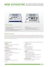
Overview<br />
<strong>NISE</strong> 2100/2100A<br />
Front<br />
Rear: <strong>NISE</strong> 2100<br />
Rear: <strong>NISE</strong> 2100A<br />
Key Features<br />
• Onboard Intel ® Atom Dual Core D525 (1.8GHz, 1M cache)<br />
processor<br />
• One DDR3 SODIMM socket, DDR3 800, maximum of 2GB<br />
memory module<br />
• 3 x Intel ® 1000/100/10 Mbps LAN ports (<strong>NISE</strong> 2100)<br />
2 x Intel ® 1000/100/10 Mbps LAN ports (<strong>NISE</strong> 2100A)<br />
• 4 x USB 2.0<br />
• 1 x VGA<br />
• 1 x DB15 GPIO connector<br />
• 4 x RS232 and 2 x RS232/422/485 with auto flow control<br />
• One external CF socket<br />
• One external SIM card holder<br />
• 9 ~ 36V DC input<br />
• ATX power mode<br />
Copyright © 2011 NEXCOM International Co., Ltd. All Rights Reserved. 1 <strong>NISE</strong> 2100, <strong>NISE</strong> 2100A, <strong>NISE</strong> 2110, <strong>NISE</strong> 2110A User Manual
Chapter 1: Product Introduction<br />
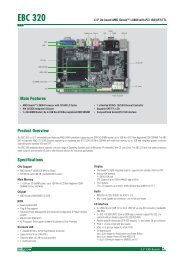
<strong>NISE</strong> 2110/2110A<br />
Front<br />
Rear: <strong>NISE</strong> 2110<br />
Rear: <strong>NISE</strong> 2110A<br />
Key Features<br />
• Onboard Intel ® Atom Dual Core D525 (1.8GHz, 1M cache)<br />
processor<br />
• One DDR3 SODIMM socket, DDR3 800, maximum of 2GB<br />
memory module<br />
• 3 x Intel ® 1000/100/10 Mbps LAN ports (<strong>NISE</strong> 2110)<br />
2 x Intel ® 1000/100/10 Mbps LAN ports (<strong>NISE</strong> 2110A)<br />
• 4 x USB 2.0<br />
• 1 x VGA<br />
• 1 x DB15 GPIO connector<br />
• 4 x RS232 and 2 x RS232/422/485 with auto flow control<br />
• One external CF socket<br />
• One external SIM card holder<br />
• 9 ~ 36V DC input<br />
• ATX power mode<br />
• 1 x PCI Expansion Slot<br />
Copyright © 2011 NEXCOM International Co., Ltd. All Rights Reserved. 2 <strong>NISE</strong> 2100, <strong>NISE</strong> 2100A, <strong>NISE</strong> 2110, <strong>NISE</strong> 2110A User Manual
Chapter 1: Product Introduction<br />
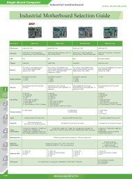
Hardware Specifications<br />
Main Board<br />
• NISB 2100 (<strong>NISE</strong> 2100/2110)<br />
NISB 2100A (<strong>NISE</strong> 2100A/2110A)<br />
• Onboard Intel ® Atom D525 dual core processor, 1.8GHz, 1M cache<br />
• Intel ® ICH8M PCH<br />
Main Memory<br />
• One DDR3 SODIMM socket<br />
• Supports up to 2GB DDR3 800 SDRAM memory module, unbuffered,<br />
non-ECC<br />
Expansion<br />
• <strong>NISE</strong> 2100/2100A<br />
- One Mini-PCIe socket (for optional WiFi or mobile wire<strong>less</strong> module)<br />
• <strong>NISE</strong> 2110/2110A<br />
- 1 x PCI expansion<br />
- One Mini-PCIe socket (for optional WiFi or mobile wire<strong>less</strong> module)<br />
I/O Interface - Front<br />
• ATX Power on/off switch<br />
• HDD access / Power status LEDs<br />
• 1 x DB15 GPIO connector<br />
• 2 x Serial ports (RS232)<br />
• 2 x USB 2.0 ports<br />
• 1 x CompactFlash socket<br />
• 1 x external SIM card holder<br />
• 2 x antenna holes (for optional WiFi or mobile wire<strong>less</strong> module)<br />
I/O Interface - Rear<br />
• 9~36V DC input<br />
• 1 x 3-pin connector for remote power on/off switch<br />
• 1 x DB15 VGA port<br />
• 1 x speaker-out jack<br />
• 3 x Intel ® GbE LAN ports (<strong>NISE</strong> 2100/2110)<br />
2 x Intel ® GbE LAN ports (<strong>NISE</strong> 2100A/2110A)<br />
• 2 x USB 2.0 ports<br />
• 4 x Serial ports (2x RS232 and 2x RS232/422/485 with auto-flow control:<br />
isolation protection on COM1 and COM2)<br />
Storage<br />
• 1 x 2.5” SATA HDD drive bay (<strong>NISE</strong> 2100/2100A)<br />
1 x 2.5” SATA HDD drive bay or optional SATA DOM module - horizontal<br />
type (<strong>NISE</strong> 2110/2110A)<br />
• 1 x external CF socket<br />
Power Requirements<br />
• ATX Power mode<br />
• DC to DC power design onboard, supports 9~36V DC<br />
• Optional 19V, 65W power adapter<br />
Dimensions<br />
• <strong>NISE</strong> 2100/2100A<br />
195mm (W) x 200mm (D) x 65mm (H) (7.7” x 7.9” x 2.6”)<br />
• <strong>NISE</strong> 2110/2110A<br />
195mm (W) x 200mm (D) x 90mm (H) (7.7” x 7.9” x 3.5”)<br />
Construction<br />
• Aluminum chassis with fan<strong>less</strong> design<br />
Copyright © 2011 NEXCOM International Co., Ltd. All Rights Reserved. 3 <strong>NISE</strong> 2100, <strong>NISE</strong> 2100A, <strong>NISE</strong> 2110, <strong>NISE</strong> 2110A User Manual
Chapter 1: Product Introduction<br />
Environment<br />
• Operating temperature - ambient with airflow:<br />
-5°C to 55°C (<strong>NISE</strong> 2100/2110)<br />
-20°C to 70°C with industrial grade devices (<strong>NISE</strong> 2100A/2110A)<br />
(According to IEC60068-2-1, IEC60068-2-2, IEC60068-2-14)<br />
• Storage temperature: -20°C to 80°C<br />
• Relative humidity: 10% to 93% (Non-Condensing)<br />
Certifications<br />
• CE approval<br />
• FCC Class A<br />
Copyright © 2011 NEXCOM International Co., Ltd. All Rights Reserved. 4 <strong>NISE</strong> 2100, <strong>NISE</strong> 2100A, <strong>NISE</strong> 2110, <strong>NISE</strong> 2110A User Manual
Chapter 1: Product Introduction<br />
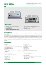
Getting to Know <strong>NISE</strong> 2100/2110 Series<br />
<strong>NISE</strong> 2100/2100A - Front Panel<br />
Antenna hole for<br />
optional WiFi<br />
GPIO<br />
Power LED<br />
Power on/off<br />
switch<br />
USB<br />
SIM<br />
CF<br />
COM5 HDD LED<br />
COM6<br />
USB<br />
Used to connect USB 2.0/1.1 devices.<br />
CF<br />
Used to insert a CompactFlash card.<br />
SIM<br />
Used to insert a SIM card.<br />
Antenna Hole for Optional WiFi<br />
Used to connect an optional Mini-PCIe WiFi module.<br />
GPIO<br />
The GPIO connector supports 4 digital input and 4 digital output.<br />
Power LED<br />
Indicates the power status of the system.<br />
HDD LED<br />
Indicates the status of the hard drive.<br />
Power On/Off Switch<br />
Press to power-on or power-off the system.<br />
COM5 and COM6<br />
Used to connect RS232 compatible serial devices.<br />
Copyright © 2011 NEXCOM International Co., Ltd. All Rights Reserved. 5 <strong>NISE</strong> 2100, <strong>NISE</strong> 2100A, <strong>NISE</strong> 2110, <strong>NISE</strong> 2110A User Manual
Chapter 1: Product Introduction<br />
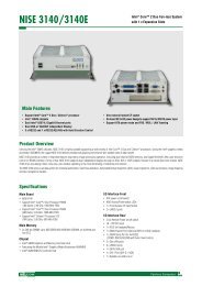
<strong>NISE</strong> 2100/2100A - Rear Panel<br />
LAN3<br />
(<strong>NISE</strong> 2100 only)<br />
VGA<br />
LAN1<br />
COM3<br />
COM1<br />
9V-36V<br />
DC Input<br />
Remote Power<br />
on/off switch<br />
LAN2<br />
USB<br />
Speaker-out<br />
COM2<br />
COM4<br />
9V-36V DC Input<br />
Used to plug a DC power cord.<br />
Output for Remote Power On/Off Switch<br />
Used to connect a remote to power on/off the system.<br />
VGA<br />
Used to connect an analog VGA monitor.<br />
USB<br />
Used to connect USB 2.0/1.1 devices.<br />
COM1 and COM2<br />
Used to connect RS232/422/485 compatible serial devices.<br />
COM3 and COM4<br />
Used to connect RS232 compatible serial devices.<br />
Speaker-out<br />
Used to connect a headphone or a speaker.<br />
LAN<br />
Used to connect the system to a local area network.<br />
<strong>NISE</strong> 2100: LAN1 to LAN3<br />
<strong>NISE</strong> 2100A: LAN1 and LAN2 only.<br />
Copyright © 2011 NEXCOM International Co., Ltd. All Rights Reserved. 6 <strong>NISE</strong> 2100, <strong>NISE</strong> 2100A, <strong>NISE</strong> 2110, <strong>NISE</strong> 2110A User Manual
Chapter 1: Product Introduction<br />
<strong>NISE</strong> 2110/2110A - Front Panel<br />
Antenna hole for<br />
optional WiFi<br />
GPIO<br />
Power LED<br />
Power on/off<br />
switch<br />
USB<br />
SIM<br />
CF<br />
COM5 HDD LED<br />
COM6<br />
USB<br />
Used to connect USB 2.0/1.1 devices.<br />
CF<br />
Used to insert a CompactFlash card.<br />
SIM<br />
Used to insert a SIM card.<br />
Antenna Hole for Optional WiFi<br />
Used to connect an optional Mini-PCIe WiFi module.<br />
GPIO<br />
The GPIO connector supports 4 digital input and 4 digital output.<br />
Power LED<br />
Indicates the power status of the system.<br />
HDD LED<br />
Indicates the status of the hard drive.<br />
Power On/Off Switch<br />
Press to power-on or power-off the system.<br />
COM5 and COM6<br />
Used to connect RS232 compatible serial devices.<br />
Copyright © 2011 NEXCOM International Co., Ltd. All Rights Reserved. 7 <strong>NISE</strong> 2100, <strong>NISE</strong> 2100A, <strong>NISE</strong> 2110, <strong>NISE</strong> 2110A User Manual
Chapter 1: Product Introduction<br />
<strong>NISE</strong> 2110/2110A - Rear Panel<br />
LAN3<br />
(<strong>NISE</strong> 2110 only)<br />
VGA<br />
LAN1<br />
COM3<br />
COM1<br />
9V-36V<br />
DC Input<br />
Remote Power<br />
on/off switch<br />
COM4<br />
PCI<br />
expansion<br />
Speaker-out COM2<br />
USB<br />
LAN2<br />
9V-36V DC Input<br />
Used to plug a DC power cord.<br />
Output for Remote Power On/Off Switch<br />
Used to connect a remote to power on/off the system.<br />
VGA<br />
Used to connect an analog VGA monitor.<br />
Speaker-out<br />
Used to connect a headphone or a speaker.<br />
USB<br />
Used to connect USB 2.0/1.1 devices.<br />
LAN<br />
Used to connect the system to a local area network.<br />
<strong>NISE</strong> 2110: LAN1 to LAN3<br />
<strong>NISE</strong> 2110A: LAN1 and LAN2 only.<br />
COM1 and COM2<br />
Used to connect RS232/422/485 compatible serial devices.<br />
COM3 and COM4<br />
Used to connect RS232 compatible serial devices.<br />
PCI Expansion<br />
Used to connect a PCI expansion card.<br />
Copyright © 2011 NEXCOM International Co., Ltd. All Rights Reserved. 8 <strong>NISE</strong> 2100, <strong>NISE</strong> 2100A, <strong>NISE</strong> 2110, <strong>NISE</strong> 2110A User Manual
Chapter 1: Product Introduction<br />
Mechanical Dimensions<br />
<strong>NISE</strong> 2100<br />
12.5<br />
25<br />
120<br />
160<br />
200<br />
195.0<br />
204.8<br />
216.8<br />
65<br />
71<br />
Copyright © 2011 NEXCOM International Co., Ltd. All Rights Reserved. 9 <strong>NISE</strong> 2100, <strong>NISE</strong> 2100A, <strong>NISE</strong> 2110, <strong>NISE</strong> 2110A User Manual
Chapter 1: Product Introduction<br />
<strong>NISE</strong> 2100A<br />
12.5<br />
25<br />
120<br />
160<br />
200<br />
195.0<br />
204.8<br />
216.8<br />
65<br />
71<br />
Copyright © 2011 NEXCOM International Co., Ltd. All Rights Reserved. 10 <strong>NISE</strong> 2100, <strong>NISE</strong> 2100A, <strong>NISE</strong> 2110, <strong>NISE</strong> 2110A User Manual
Chapter 1: Product Introduction<br />
<strong>NISE</strong> 2110<br />
25<br />
120<br />
160<br />
200<br />
12.5<br />
195<br />
204.8<br />
216.8<br />
90<br />
96<br />
Copyright © 2011 NEXCOM International Co., Ltd. All Rights Reserved. 11 <strong>NISE</strong> 2100, <strong>NISE</strong> 2100A, <strong>NISE</strong> 2110, <strong>NISE</strong> 2110A User Manual
Chapter 1: Product Introduction<br />
<strong>NISE</strong> 2110A<br />
12.5<br />
25<br />
120<br />
160<br />
200<br />
195<br />
204.8<br />
216.8<br />
90<br />
96<br />
Copyright © 2011 NEXCOM International Co., Ltd. All Rights Reserved. 12 <strong>NISE</strong> 2100, <strong>NISE</strong> 2100A, <strong>NISE</strong> 2110, <strong>NISE</strong> 2110A User Manual
Chapter 2: Jumpers and Connectors<br />
Chapter 2: Jumpers and Connectors<br />
This chapter describes the jumpers and connectors on the motherboard.<br />
Note that the following procedures are generic for all <strong>NISE</strong> 2100/2110<br />
series.<br />
Before You Begin<br />
• Ensure you have a stable, clean working environment. Dust and dirt can<br />
get into components and cause a malfunction. Use containers to keep<br />
small components separated.<br />
• Adequate lighting and proper tools can prevent you from accidentally<br />
damaging the internal components. Most of the procedures that follow<br />
require only a few simple tools, including the following:<br />
• A Philips screwdriver<br />
• A flat-tipped screwdriver<br />
• A set of jewelers Screwdrivers<br />
• A grounding strap<br />
• An anti-static pad<br />
• Using your fingers can disconnect most of the connections. It is recommended<br />
that you do not use needle-nosed pliers to disconnect connections<br />
as these can damage the soft metal or plastic parts of the connectors.<br />
• Before working on internal components, make sure that the power<br />
is off. Ground yourself before touching any internal components, by<br />
touching a metal object. Static electricity can damage many of the electronic<br />
components. Humid environment tend to have <strong>less</strong> static electricity<br />
than dry environments. A grounding strap is warranted whenever<br />
danger of static electricity exists.<br />
Precautions<br />
<strong>Computer</strong> components and electronic circuit boards can be damaged by<br />
discharges of static electricity. Working on the computers that are still connected<br />
to a power supply can be extremely dangerous.<br />
Follow the guidelines below to avoid damage to your computer or yourself:<br />
• Always disconnect the unit from the power outlet whenever you are<br />
working inside the case.<br />
• If possible, wear a grounded wrist strap when you are working inside<br />
the computer case. Alternatively, discharge any static electricity by<br />
touching the bare metal chassis of the unit case, or the bare metal body<br />
of any other grounded appliance.<br />
• Hold electronic circuit boards by the edges only. Do not touch the com-<br />
ponents on the board un<strong>less</strong> it is necessary to do so. Don’t flex or stress<br />
the circuit board.<br />
• Leave all components inside the static-proof packaging that they<br />
shipped with until they are ready for installation.<br />
• Use correct screws and do not over tighten screws.<br />
Copyright © 2011 NEXCOM International Co., Ltd. All Rights Reserved. 13<br />
<strong>NISE</strong> 2100, <strong>NISE</strong> 2100A, <strong>NISE</strong> 2110, <strong>NISE</strong> 2110A User Manual
Chapter 2: Jumpers and Connectors<br />
Jumper Settings<br />
A jumper is the simplest kind of electric switch. It consists of two metal<br />
pins and a cap. When setting the jumpers, ensure that the jumper caps are<br />
placed on the correct pins. When the jumper cap is placed on both pins,<br />
the jumper is short. If you remove the jumper cap, or place the jumper<br />
cap on just one pin, the jumper is open.<br />
Refer to the illustrations below for examples of what the 2-pin and 3-pin<br />
jumpers look like when they are short (on) and open (off).<br />
Two-Pin Jumpers: Open (Left) and Short (Right)<br />
Three-Pin Jumpers: Pins 1 and 2 Are Short<br />
Copyright © 2011 NEXCOM International Co., Ltd. All Rights Reserved. 14<br />
<strong>NISE</strong> 2100, <strong>NISE</strong> 2100A, <strong>NISE</strong> 2110, <strong>NISE</strong> 2110A User Manual
1<br />
Chapter 2: Jumpers and Connectors<br />
Locations of the Jumpers and Connectors<br />
NISB 2100<br />
The figure below is the top view of the NISB 2100 main board which is the main board used in the <strong>NISE</strong> 2100 Series system. It shows the locations of the<br />
jumpers and connectors.<br />
CON2<br />
CON1<br />
J2<br />
CN1<br />
JP1<br />
J10<br />
J3<br />
SW1<br />
LED1<br />
J5<br />
CN3<br />
VGA1<br />
JP2<br />
SODIMM<br />
J4<br />
COM1<br />
LAN1<br />
COM2<br />
CON3<br />
CN5<br />
COM3<br />
IDE1<br />
J6<br />
COM4<br />
USB1<br />
J9<br />
J7<br />
J8<br />
JP3<br />
JP4<br />
Copyright © 2011 NEXCOM International Co., Ltd. All Rights Reserved. 15<br />
<strong>NISE</strong> 2100, <strong>NISE</strong> 2100A, <strong>NISE</strong> 2110, <strong>NISE</strong> 2110A User Manual
Chapter 2: Jumpers and Connectors<br />
The figure below is the bottom view of the NISB 2100 main board.<br />
J13<br />
J10<br />
J12 J11<br />
J15<br />
J14<br />
IDE2<br />
CN6<br />
CON4<br />
Copyright © 2011 NEXCOM International Co., Ltd. All Rights Reserved. 16<br />
<strong>NISE</strong> 2100, <strong>NISE</strong> 2100A, <strong>NISE</strong> 2110, <strong>NISE</strong> 2110A User Manual
Chapter 2: Jumpers and Connectors<br />
Jumpers<br />
Clear CMOS<br />
Connector size: 1x3 3-pin header, 2.54 mm pitch<br />
Connector location: JP3<br />
COM3 RS232 RI Pin Power Select<br />
Connector type: 1x5 5-pin header 2.54mm -M-180<br />
Connector location: J9<br />
1 3<br />
1<br />
Pin<br />
Settings<br />
1-2 On Normal<br />
2-3 On CMOS Clear<br />
1-2 On: default<br />
Pin<br />
Definition<br />
1 NC<br />
2 IRTCRST#<br />
3 GND<br />
5<br />
Pin<br />
Settings<br />
1-2 +5V<br />
2-3 +12V<br />
4-5 RING<br />
4-5 On: default<br />
Pin<br />
Definition<br />
1 VCC5<br />
2 RING_T<br />
3 +12V<br />
4 RING_T<br />
5 RING<br />
Copyright © 2011 NEXCOM International Co., Ltd. All Rights Reserved. 17<br />
<strong>NISE</strong> 2100, <strong>NISE</strong> 2100A, <strong>NISE</strong> 2110, <strong>NISE</strong> 2110A User Manual
Chapter 2: Jumpers and Connectors<br />
Panel CCFL LVDS Backlight Power Select<br />
Connector size: 1x3 3-pin header, 2.54 mm pitch<br />
Connector location: JP1<br />
1 3<br />
Pin<br />
Settings<br />
1 VCC3 (3.3V)<br />
2 VCC_LCD<br />
3 VCC5(+5V)<br />
1-2 On: default<br />
Copyright © 2011 NEXCOM International Co., Ltd. All Rights Reserved. 18<br />
<strong>NISE</strong> 2100, <strong>NISE</strong> 2100A, <strong>NISE</strong> 2110, <strong>NISE</strong> 2110A User Manual
Chapter 2: Jumpers and Connectors<br />
Connector Pin Definitions<br />
External I/O Interface - Front Panel<br />
USB Ports<br />
Connector type: Dual USB port<br />
Connector location: USB1<br />
COM5 Serial Port<br />
Connector type: DB-9 port<br />
Connector location: COM2<br />
1<br />
5<br />
6 9<br />
Pin Definition Pin Definition<br />
1 USB_VCC(5V) 5 USB_VCC(5V)<br />
2 DATA_N 6 DATA_N<br />
3 DATA_P 7 DATA_P<br />
4 GND 8 GND<br />
Pin Definition Pin Definition<br />
1 COM5_DCD 6 COM5_DSR<br />
2 COM5_RXD 7 COM5_RTS<br />
3 COM5_TXD 8 COM5_CTS<br />
4 COM5_DTR 9 COM5_RI<br />
5 GND<br />
Copyright © 2011 NEXCOM International Co., Ltd. All Rights Reserved. 19<br />
<strong>NISE</strong> 2100, <strong>NISE</strong> 2100A, <strong>NISE</strong> 2110, <strong>NISE</strong> 2110A User Manual
Chapter 2: Jumpers and Connectors<br />
COM6 Serial Port<br />
Connector type: DB-9 port<br />
Connector location: COM1<br />
1<br />
5<br />
GPIO Connector<br />
(4 digital input and 4 digital output)<br />
Connector type: DB-15 port, 2x5 10-pin header, 2.0 mm-M-180<br />
Connector location: J8<br />
1 2<br />
5<br />
1<br />
6 9<br />
9 10<br />
15<br />
11<br />
Pin Definition Pin Definition<br />
1 COM6_DCD 6 COM6_DSR<br />
2 COM6_RXD 7 COM6_RTS<br />
3 COM6_TXD 8 COM6_CTS<br />
4 COM6_DTR 9 COM6_RI<br />
5 GND<br />
Pin Definition Pin Definition<br />
1 +5V 2 GND<br />
3 GPO 4 GPI<br />
5 GPO 6 GPI<br />
7 GPO 8 GPI<br />
9 GPO 10 GPI<br />
Copyright © 2011 NEXCOM International Co., Ltd. All Rights Reserved. 20<br />
<strong>NISE</strong> 2100, <strong>NISE</strong> 2100A, <strong>NISE</strong> 2110, <strong>NISE</strong> 2110A User Manual
Chapter 2: Jumpers and Connectors<br />
Status Indicators<br />
PWR<br />
ATX Power On/Off Switch<br />
Connector location: SW1<br />
HDD<br />
Status<br />
LED Color<br />
PWR Green<br />
HDD Yellow<br />
Pin<br />
Definition<br />
On Blue light<br />
Off Red light<br />
Pin Definition Pin Definition<br />
1 GND 2 PBT_PU<br />
3 PBT_PU 4 GND<br />
A1 PWRLED_N C1 PWRLED_P<br />
Copyright © 2011 NEXCOM International Co., Ltd. All Rights Reserved. 21<br />
<strong>NISE</strong> 2100, <strong>NISE</strong> 2100A, <strong>NISE</strong> 2110, <strong>NISE</strong> 2110A User Manual
Chapter 2: Jumpers and Connectors<br />
External I/O Interface - Rear Panel<br />
9-36V DC Input<br />
Connector type: 2P Phoenix Contact 5.08mm Power Connector<br />
Connector location: CON2<br />
Remote Power On/Off Switch<br />
Connector type: 3-pin switch<br />
Connector location: J5<br />
2 1<br />
1 3<br />
Pin<br />
Definition<br />
1 GND<br />
2 VIN(9~36V)<br />
Pin<br />
Definition<br />
1 GND<br />
2 PWR_ON<br />
3 PS_ON<br />
Copyright © 2011 NEXCOM International Co., Ltd. All Rights Reserved. 22<br />
<strong>NISE</strong> 2100, <strong>NISE</strong> 2100A, <strong>NISE</strong> 2110, <strong>NISE</strong> 2110A User Manual
Chapter 2: Jumpers and Connectors<br />
VGA Port<br />
Connector type: DB-15 port, 15-pin D-Sub<br />
Connector location: VGA1<br />
Speaker-out Jack<br />
Connector type: 6-pin jack<br />
Connector location: CN3<br />
5<br />
1<br />
15<br />
11<br />
Pin Definition Pin Definition<br />
1 RED_VGA 9 VGA_VCC(5V)<br />
2 GREEN_VGA 10 GND<br />
3 BLUE_VGA 11 NC<br />
4 NC 12 DDCDATA_VGA<br />
5 GND 13 HSYNC_VGA<br />
6 VGADET 14 VSYNC_VGA<br />
7 GND 15 DDCCLK_VGA<br />
8 GND<br />
Pin<br />
Definition<br />
1 Speak Out - R<br />
2 Speak Out - JD<br />
3 NC<br />
4 Speak Out - L<br />
5 GND<br />
6 GND<br />
Copyright © 2011 NEXCOM International Co., Ltd. All Rights Reserved. 23<br />
<strong>NISE</strong> 2100, <strong>NISE</strong> 2100A, <strong>NISE</strong> 2110, <strong>NISE</strong> 2110A User Manual
Chapter 2: Jumpers and Connectors<br />
LAN1 and LAN2 Ports<br />
Connector type: RJ45 port with LEDs<br />
Connector location: LAN1<br />
Act<br />
Link<br />
LAN1<br />
LAN2<br />
LAN2<br />
Pin Definition Pin Definition<br />
A1 LAN2M0P A7 LAN2M3P<br />
A2 LAN2M0N A8 LAN2M3N<br />
A3 LAN2M1P A9 LAN2LINK<br />
A4 LAN2M2P A10 LAN2ACTP<br />
A5 LAN2M2N A11 LAN2ACT#<br />
A6 LAN2M1N A12 LAN2LINKP<br />
Act<br />
Yellow<br />
Blinking<br />
Status<br />
Data Activity<br />
Off No Acitivity<br />
Link<br />
Green<br />
Always Lighted<br />
Status<br />
Linked<br />
Off No Link<br />
LAN1<br />
Pin Definition Pin Definition<br />
B1 LAN1M0P B7 LAN1M3P<br />
B2 LAN1M0N B8 LAN1M3N<br />
B3 LAN1M1P B9 LAN1LINK<br />
B4 LAN1M2P B10 LAN1ACTP<br />
B5 LAN1M2N B11 LAN1ACT#<br />
B6 LAN1M1N B12 LAN1LINKP<br />
Copyright © 2011 NEXCOM International Co., Ltd. All Rights Reserved. 24<br />
<strong>NISE</strong> 2100, <strong>NISE</strong> 2100A, <strong>NISE</strong> 2110, <strong>NISE</strong> 2110A User Manual
Chapter 2: Jumpers and Connectors<br />
LAN3 (<strong>NISE</strong> 2100/2110 only) and Dual USB Ports<br />
Connector size: RJ45 and Dual USB<br />
Connector location: CON3<br />
Act<br />
Link<br />
LAN3<br />
Pin Definition Pin Definition<br />
9 LAN3M0P 17 LAN3ACTP<br />
10 LAN3M0N 18 LAN3_LEDACT#<br />
11 LAN3M1P 19 LAN3LINKP<br />
12 LAN3M2P 20 LAN3_LEDLINK<br />
13 LAN3M2N 21 GND<br />
14 LAN3M1N 24 GND<br />
15 LAN3M3P 25 GND<br />
16 LAN3M3N 28 GND<br />
USB<br />
Pin Definition Pin Definition<br />
1 USB_VCC(5V) 5 USB_VCC(5V)<br />
2 DATA_N 6 DATA_N<br />
3 DATA_P 7 DATA_P<br />
4 GND 8 GND<br />
23 GND 22 GND<br />
27 GND 28 GND<br />
Copyright © 2011 NEXCOM International Co., Ltd. All Rights Reserved. 25<br />
<strong>NISE</strong> 2100, <strong>NISE</strong> 2100A, <strong>NISE</strong> 2110, <strong>NISE</strong> 2110A User Manual
Chapter 2: Jumpers and Connectors<br />
COM1 and COM2 Ports<br />
Connector size: DB-9 port<br />
Connector location: COM3<br />
6 1 5 9<br />
A<br />
RS485<br />
Pin Definition Pin Definition<br />
1 TXD- 6 Reserved<br />
2 TXD+ 7 Reserved<br />
3 Reserved 8 Reserved<br />
4 Reserved 9 Reserved<br />
5 Reserved<br />
6 1 5 9 B<br />
COM1A<br />
Pin Definition Pin Definition<br />
1 COM1_DCD 6 COM1_DSR<br />
2 COM1_RXD 7 COM1_RTS<br />
3 COM1_TXD 8 COM1_CTS<br />
4 COM1_DTR 9 COM1_RI<br />
5 GND<br />
RS422<br />
Pin Definition Pin Definition<br />
1 TXD- 6 RTS-<br />
2 TXD+ 7 RTS+<br />
3 RXD+ 8 CTS+<br />
4 RXD- 9 CTS-<br />
5 GND<br />
COM2B<br />
Pin Definition Pin Definition<br />
1 COM2_DCD 6 COM2_DSR<br />
2 COM2_RXD 7 COM2_RTS<br />
3 COM2_TXD 8 COM2_CTS<br />
4 COM2_DTR 9 COM2_RI<br />
5 GND<br />
Copyright © 2011 NEXCOM International Co., Ltd. All Rights Reserved. 26<br />
<strong>NISE</strong> 2100, <strong>NISE</strong> 2100A, <strong>NISE</strong> 2110, <strong>NISE</strong> 2110A User Manual
Chapter 2: Jumpers and Connectors<br />
COM3 and COM4 Ports<br />
Connector size: DB-9 port<br />
Connector location: COM4<br />
USB 8-9 Connector<br />
Connector size: 1x6 6-pin JST wafer, 2.5 mm pitch<br />
Connector location: J7<br />
6 1 5 9<br />
A<br />
6 1<br />
6 1 5 9 B<br />
COM3A<br />
Pin Definition Pin Definition<br />
1 COM3_DCD 6 COM3_DSR<br />
2 COM3_RXD 7 COM3_RTS<br />
3 COM3_TXD 8 COM3_CTS<br />
4 COM3_DTR 9 COM3_RI<br />
5 GND<br />
Pin<br />
Definition<br />
1 USB_VCC45<br />
2 USB_8N<br />
3 USB_8P<br />
4 USB_9N<br />
5 USB_9P<br />
6 USB_GND<br />
COM4B<br />
Pin Definition Pin Definition<br />
1 COM4_DCD 6 COM4_DSR<br />
2 COM4_RXD 7 COM4_RTS<br />
3 COM4_TXD 8 COM4_CTS<br />
4 COM4_DTR 9 COM4_RI<br />
5 GND<br />
Copyright © 2011 NEXCOM International Co., Ltd. All Rights Reserved. 27<br />
<strong>NISE</strong> 2100, <strong>NISE</strong> 2100A, <strong>NISE</strong> 2110, <strong>NISE</strong> 2110A User Manual
Chapter 2: Jumpers and Connectors<br />
Internal Connectors<br />
COM5 Connector<br />
Connector type: 2x5 10-pin boxed header, 1.0mm<br />
Connector location: J14<br />
COM6 Connector<br />
Connector type: 2x5 10-pin boxed header, 1.0mm<br />
Connector location: J15<br />
1 10<br />
1 10<br />
Pin Definition Pin Definition<br />
1 SIO_DCD#5 2 SIO_RXD5<br />
3 SIO_TXD5 4 SIO_DTR#5<br />
5 IO_GND 6 SIO_DSR#5<br />
7 SIO_RTS#5 8 SIO_CTS#5<br />
9 SIO_RI#5 10 IO_GND<br />
Pin Definition Pin Definition<br />
1 SIO_DCD#6 2 SIO_RXD6<br />
3 SIO_TXD6 4 SIO_DTR#6<br />
5 IO_GND 6 SIO_DSR#6<br />
7 SIO_RTS#6 8 SIO_CTS#6<br />
9 SIO_RI#6 10 IO_GND<br />
Copyright © 2011 NEXCOM International Co., Ltd. All Rights Reserved. 28<br />
<strong>NISE</strong> 2100, <strong>NISE</strong> 2100A, <strong>NISE</strong> 2110, <strong>NISE</strong> 2110A User Manual
Chapter 2: Jumpers and Connectors<br />
Remote Power On/Off Switch<br />
Connector type: 1x2 2-pin header, JST 2.0mm<br />
Connector location: J3<br />
CPU <strong>Fan</strong> Connector<br />
Connector type: 1x4, 4-pin Wafer, 2.54mm-M-180<br />
Connector location: J2<br />
1<br />
2<br />
Pin<br />
Definition<br />
1 PSON#<br />
2 GND<br />
1<br />
4<br />
Pin<br />
Definition<br />
1 GND<br />
2 VCC_12<br />
3 CPU1_FAN_SPEED<br />
4 CPU1_FANPWM<br />
Copyright © 2011 NEXCOM International Co., Ltd. All Rights Reserved. 29<br />
<strong>NISE</strong> 2100, <strong>NISE</strong> 2100A, <strong>NISE</strong> 2110, <strong>NISE</strong> 2110A User Manual
Chapter 2: Jumpers and Connectors<br />
Internal Power/HDD/LAN Power/LAN Active LED (RTC Connector)<br />
Connector type: 2x7 14-pin header 2.54mm-M-180<br />
Connector location: J4<br />
SMBus Pin Header<br />
Connector type: 1x3 3-pin header 2.54mm-M-180<br />
Connector location: JP4<br />
2<br />
14<br />
1<br />
1 13<br />
3<br />
Power LED<br />
H/W RESET<br />
HDD LED<br />
LAN2 ACT LED<br />
LAN1 LINK LED LAN2 LINK LED<br />
LAN1 ACT LED<br />
Pin<br />
Definition<br />
1 SMbus_CLK<br />
2 SMbus_data<br />
3 GND<br />
Pin Description Pin Description<br />
1 POWER_OK 2 VCC_LEDPOWER<br />
3 HDD_LED# 4 HDD_LEDPOWER<br />
5 LAN1_LINK# 6 LAN1LINK_LEDPOWER<br />
7 LAN1_ACT# 8 LAN1ACT_LEDPOWER<br />
9 LAN2_LINK# 10 LAN2LINK_LEDPOWER<br />
11 LAN2_ACT# 12 LAN2ACT_LEDPOWER<br />
13 H/W RESET 14 GND<br />
Copyright © 2011 NEXCOM International Co., Ltd. All Rights Reserved. 30<br />
<strong>NISE</strong> 2100, <strong>NISE</strong> 2100A, <strong>NISE</strong> 2110, <strong>NISE</strong> 2110A User Manual
Chapter 2: Jumpers and Connectors<br />
Mic-in Connector<br />
Connector type: 1x4 4-pin header 2.54mm-M-180<br />
Connector location: JP2<br />
Power Output Connector<br />
Connector type: 2x2 4-pin AUX 3.5mm<br />
Connector location: CON1<br />
1 4<br />
1<br />
3<br />
Pin<br />
Definition<br />
1 Mic-in L<br />
2 Mic JD<br />
3 GND<br />
4 Mic-in R<br />
2 4<br />
Pin<br />
Definition<br />
1 GND<br />
2 GND<br />
3 VIN Power<br />
4 VIN Power<br />
Copyright © 2011 NEXCOM International Co., Ltd. All Rights Reserved. 31<br />
<strong>NISE</strong> 2100, <strong>NISE</strong> 2100A, <strong>NISE</strong> 2110, <strong>NISE</strong> 2110A User Manual
Chapter 2: Jumpers and Connectors<br />
LVDS Connector<br />
Connector type: 20-pin DF13-20DP 1.25mm<br />
Connector location: CN1<br />
Panel CCFL Connector<br />
Connector type: 1x7 7-pin header JST-2.5mm-M-180<br />
Connector location: J1<br />
1<br />
MH1<br />
19<br />
7<br />
2<br />
20<br />
MH2<br />
Pin Definition Pin Definition<br />
1 LVDS_DDCCLK 2 LVDS_DDCDATA<br />
3 VCC_LCD(5V Or3.3V) 4 LVDS_A0P<br />
5 NC 6 LVDS_A0N<br />
7 NC 8 VCC_LCD(5V Or3.3V)<br />
9 GND 10 LVDS_A1P<br />
11 LVDS_ACLKP 12 LVDS_A1N<br />
13 LVDS_ACLKN 14 GND<br />
15 GND 16 V_INV (12V)<br />
17 LVDS_A2P 18 V_INV (12V)<br />
19 LVDS_A2N 20 GND<br />
1<br />
Pin<br />
Definition<br />
1 Vcc5<br />
2 V_INV (12V)<br />
3 V_INV (12V)<br />
4 CCFLBKLTCTRL<br />
5 GND<br />
6 GND<br />
7 M_BKLTEN<br />
Copyright © 2011 NEXCOM International Co., Ltd. All Rights Reserved. 32<br />
<strong>NISE</strong> 2100, <strong>NISE</strong> 2100A, <strong>NISE</strong> 2110, <strong>NISE</strong> 2110A User Manual
Chapter 2: Jumpers and Connectors<br />
CompactFlash<br />
Connector type: CompactFlash Type I/II H:6.3mm SMD<br />
Connector location: IDE1<br />
Pin Description Pin Description<br />
1 GND 2 SDD3A<br />
3 SDD4A 4 SDD5A<br />
5 SDD6A 6 SDD7A<br />
7 SDCS#1 8 GND<br />
9 GND 10 GND<br />
11 GND 12 GND<br />
13 VCC 14 GND<br />
15 GND 16 GND<br />
17 GND 18 SDA2A<br />
19 SDA1A 20 SDA0A<br />
21 SDD0A 22 SDD1A<br />
23 SDD2A 24 NC<br />
25 CF_CD2# 26 CF_CD1#<br />
27 SDD11A 28 SDD12A<br />
Pin Description Pin Description<br />
29 SDD13A 30 SDD14A<br />
31 SDD15A 32 SDCS#3<br />
33 NC 34 SDIOR#<br />
35 SDIOW# 36 VCC<br />
37 HDIRQ14 38 VCC<br />
39 CF_SEL# 40 NC<br />
41 IDERST# 42 SIORDY<br />
43 SDREQ 44 SDDACK#<br />
45 IDEACTP# 46 DIAG#<br />
47 SDD8A 48 SDD9A<br />
49 SDD10A 50 GND<br />
Copyright © 2011 NEXCOM International Co., Ltd. All Rights Reserved. 33<br />
<strong>NISE</strong> 2100, <strong>NISE</strong> 2100A, <strong>NISE</strong> 2110, <strong>NISE</strong> 2110A User Manual
Chapter 2: Jumpers and Connectors<br />
Mini-PCIe Slot<br />
Connector location: CN5<br />
1 2<br />
51 52<br />
Pin Definition Pin Definition<br />
1 PCIE_WAKE# 2 +V3.3A_MINI<br />
3 NC 4 GND<br />
5 NC 6 +V1.5S_MINI<br />
7 PCIE_MINI_CLKREQ#1 8 SIM_PWER<br />
9 GND 10 SIM_DATA<br />
11 CLK_N 12 SIM_CLK<br />
13 CLK_P 14 SIM_REST<br />
15 GND 16 SIM_VCCP<br />
17 NC 18 GND<br />
19 NC 20 MINICARD1_DIS#<br />
21 GND 22 PCI_RST<br />
23 PCIeRX_N 24 +V3.3A_MINI<br />
25 PCIeRX_P 26 GND<br />
27 GND 28 +V1.5S_MINI<br />
29 GND 30 SMB_CLK<br />
Pin Definition Pin Definition<br />
31 PCIeTX_N 32 SMB_DATA<br />
33 PCIeTX_P 34 GND<br />
35 GND 36 USB_DATA_N<br />
37 GND 38 USB_DATA_P<br />
39 +V3.3A_MINI 40 GND<br />
41 +V3.3A_MINI 42 NC<br />
43 GND 44 LED_WLAN_N<br />
45 NC 46 NC<br />
47 NC 48 +V1.5S_MINI<br />
49 NC 50 GND<br />
51 NC 52 +V3.3A_MINI<br />
MH1 GND MH2 GND<br />
MH3 GND MH4 GND<br />
MH6 GND<br />
Copyright © 2011 NEXCOM International Co., Ltd. All Rights Reserved. 34<br />
<strong>NISE</strong> 2100, <strong>NISE</strong> 2100A, <strong>NISE</strong> 2110, <strong>NISE</strong> 2110A User Manual
Chapter 2: Jumpers and Connectors<br />
PCI Slot (Low Profile)<br />
Connector type: 120-pin H:9.6mm 180D GOLD FLASH DIP 5V<br />
Connector location: CN6<br />
A1<br />
B1<br />
C1<br />
D1<br />
A30<br />
B30<br />
C30<br />
D30<br />
Definition<br />
Pin A B Pin A B<br />
1 TRST# -12V 32 AD16 AD17<br />
2 +12V TCK 33 +3.3V C/BE2#<br />
3 TMS GND 34 FRAME# GND<br />
4 TDI TDO 35 GND IRDY#<br />
5 +5V +5V 36 TRDY# +3.3V<br />
6 INTA# +5V 37 GND DEVSEL#<br />
7 INTC# INTB# 38 STOP# GND<br />
8 +5V INTD# 39 +3.3V LOCK#<br />
9 RSV1 PRSNT1# 40 SMBCLK PERR#<br />
10 +5V RSV5 41 SMBDAT +3.3V<br />
11 RSV2 PRSNT2# 42 GND SERR#<br />
12 GND GND 43 PAR +3.3V<br />
13 GND GND 44 AD15 C/BE1#<br />
14 +3.3Vaux RSV6 45 +3.3V AD14<br />
15 RST# GRPIMD 46 AD13 GND<br />
16 +5V CLK 47 AD11 AD12<br />
17 GNT# GND 48 GND AD10<br />
18 GND REQ# 49 AD9 GND<br />
19 PME# +5V<br />
20 AD30 AD31<br />
CONNECTOR KEY<br />
21 +3.3V AD29 52 C/BE0# AD8<br />
22 AD28 GND 53 +3.3V AD7<br />
23 AD26 AD27 54 AD6 +3.3V<br />
24 GND AD25 55 AD4 AD5<br />
25 AD24 +3.3V 56 GND AD3<br />
26 IDSEL C/BE3# 57 AD2 GND<br />
27 +3.3V AD23 58 AD0 AD1<br />
28 AD22 GND 59 +5V +5V<br />
29 AD20 AD21 60 REQ64# ACK64#<br />
30 GND AD19 61 +5V +5V<br />
31 AD18 +3.3V 62 +5V +5V<br />
Copyright © 2011 NEXCOM International Co., Ltd. All Rights Reserved. 35<br />
<strong>NISE</strong> 2100, <strong>NISE</strong> 2100A, <strong>NISE</strong> 2110, <strong>NISE</strong> 2110A User Manual
Chapter 3: System Setup<br />
Chapter 3: System Setup<br />
Removing the Chassis Cover<br />
Prior to removing the chassis cover, make sure the unit’s power is<br />
off and disconnected from the power sources to prevent electric<br />
shock or system damage.<br />
3. The SODIMM, Mini-PCIe and CompactFlash sockets are readily accessible<br />
upon removing the cover.<br />
1. The screws on the top cover are used to secure the cover to the chassis.<br />
2. Remove these screws and then put them in a safe place for later use.<br />
Mini-PCIe<br />
CompactFlash<br />
SODIMM<br />
The dots denote the locations of the screws.<br />
Copyright © 2011 NEXCOM International Co., Ltd. All Rights Reserved. 36<br />
<strong>NISE</strong> 2100, <strong>NISE</strong> 2100A, <strong>NISE</strong> 2110, <strong>NISE</strong> 2110A User Manual
Chapter 3: System Setup<br />
Installing a SODIMM<br />
1. Locate the SODIMM socket on the board.<br />
2. Insert the module into the socket at an approximately 30 degrees<br />
angle. Apply firm even pressure to each end of the module until it slips<br />
into the socket. The gold-plated connector on the edge of the module<br />
will almost completely disappear inside the socket.<br />
SODIMM<br />
socket<br />
SODIMM<br />
Copyright © 2011 NEXCOM International Co., Ltd. All Rights Reserved. 37<br />
<strong>NISE</strong> 2100, <strong>NISE</strong> 2100A, <strong>NISE</strong> 2110, <strong>NISE</strong> 2110A User Manual
Chapter 3: System Setup<br />
3. Push the module down until the clips on both sides of the socket lock<br />
into position. You will hear a distinctive “click”, indicating the module<br />
is correctly locked into position.<br />
Clip<br />
Clip<br />
Copyright © 2011 NEXCOM International Co., Ltd. All Rights Reserved. 38<br />
<strong>NISE</strong> 2100, <strong>NISE</strong> 2100A, <strong>NISE</strong> 2110, <strong>NISE</strong> 2110A User Manual
Chapter 3: System Setup<br />
Installing a Wire<strong>less</strong> LAN Module<br />
1. Locate the Mini PCI Express slot on the board.<br />
2. Insert the wire<strong>less</strong> LAN module into the Mini PCI Express slot at a 45<br />
degrees angle until the gold-plated connector on the edge of the module<br />
completely disappears inside the slot.<br />
Mini PCI Express<br />
slot<br />
Mini PCI Express<br />
slot<br />
Wire<strong>less</strong> LAN<br />
module<br />
Copyright © 2011 NEXCOM International Co., Ltd. All Rights Reserved. 39<br />
<strong>NISE</strong> 2100, <strong>NISE</strong> 2100A, <strong>NISE</strong> 2110, <strong>NISE</strong> 2110A User Manual
Chapter 3: System Setup<br />
3. Push the module down and then secure it with mounting screws.<br />
Mounting<br />
screw<br />
Copyright © 2011 NEXCOM International Co., Ltd. All Rights Reserved. 40<br />
<strong>NISE</strong> 2100, <strong>NISE</strong> 2100A, <strong>NISE</strong> 2110, <strong>NISE</strong> 2110A User Manual
Chapter 3: System Setup<br />
Installing a SATA Hard Drive (<strong>NISE</strong> 2100/2100A)<br />
1. With the bottom side of the chassis facing up, remove the mounting<br />
screws of the bottom cover and then remove the cover.<br />
2. Remove the 4 mounting screws that secure the drive bay to the chassis.<br />
Drive bay<br />
Bottom<br />
cover<br />
Mounting<br />
screw<br />
Mounting<br />
screw<br />
Copyright © 2011 NEXCOM International Co., Ltd. All Rights Reserved. 41<br />
<strong>NISE</strong> 2100, <strong>NISE</strong> 2100A, <strong>NISE</strong> 2110, <strong>NISE</strong> 2110A User Manual
Chapter 3: System Setup<br />
3. Noticeable are 2 cables upon removing the drive bay. These are the<br />
SATA data cable and the SATA power cable.<br />
4. The drive bay is used to hold a SATA hard drive.<br />
SATA power<br />
cable<br />
SATA data<br />
cable<br />
Copyright © 2011 NEXCOM International Co., Ltd. All Rights Reserved. 42<br />
<strong>NISE</strong> 2100, <strong>NISE</strong> 2100A, <strong>NISE</strong> 2110, <strong>NISE</strong> 2110A User Manual
Chapter 3: System Setup<br />
5. Place the SATA hard drive on the drive bay.<br />
Align the mounting holes that are on the sides of the SATA drive with<br />
the mounting holes on the drive bay and then use the provided mounting<br />
screws to secure the drive in place.<br />
6. Mount the drive bay back into the chassis and then secure it with<br />
mounting screws.<br />
7. Connect the SATA data cable and SATA power cable to the connectors<br />
on the SATA drive.<br />
Connector<br />
side of the<br />
SATA drive<br />
Mounting<br />
screw<br />
SATA drive<br />
Mounting<br />
screw<br />
SATA data<br />
cable<br />
SATA power<br />
cable<br />
Copyright © 2011 NEXCOM International Co., Ltd. All Rights Reserved. 43<br />
<strong>NISE</strong> 2100, <strong>NISE</strong> 2100A, <strong>NISE</strong> 2110, <strong>NISE</strong> 2110A User Manual
Chapter 3: System Setup<br />
Installing a SATA Hard Drive (<strong>NISE</strong> 2110/2110A)<br />
1. With the bottom side of the chassis facing up, remove the mounting<br />
screws of the bottom cover and then remove the cover.<br />
2. Remove the 4 mounting screws that secure the drive bay to the chassis<br />
and then remove the drive bay.<br />
Drive bay<br />
Bottom<br />
cover<br />
Mounting<br />
screw<br />
Mounting<br />
screw<br />
Copyright © 2011 NEXCOM International Co., Ltd. All Rights Reserved. 44<br />
<strong>NISE</strong> 2100, <strong>NISE</strong> 2100A, <strong>NISE</strong> 2110, <strong>NISE</strong> 2110A User Manual
Chapter 3: System Setup<br />
3. The drive bay is used to hold a SATA hard drive. 4. Place the SATA hard drive on the drive bay. Align the mounting holes<br />
that are on the SATA drive with the mounting holes on the drive bay.<br />
Connector<br />
side of the<br />
SATA drive<br />
Drive bay<br />
SATA drive<br />
Copyright © 2011 NEXCOM International Co., Ltd. All Rights Reserved. 45<br />
<strong>NISE</strong> 2100, <strong>NISE</strong> 2100A, <strong>NISE</strong> 2110, <strong>NISE</strong> 2110A User Manual
Chapter 3: System Setup<br />
5. Turn to the other side of the bay and then use the provided mounting<br />
screws to secure the SATA drive to the drive bay.<br />
6. Connect the SATA data cable and SATA power cable to the connectors<br />
on the SATA drive.<br />
SATA data cable<br />
Connector<br />
side of the<br />
SATA drive<br />
Mounting<br />
screw<br />
SATA power cable<br />
Copyright © 2011 NEXCOM International Co., Ltd. All Rights Reserved. 46<br />
<strong>NISE</strong> 2100, <strong>NISE</strong> 2100A, <strong>NISE</strong> 2110, <strong>NISE</strong> 2110A User Manual
Chapter 3: System Setup<br />
7. Mount the drive bay back into the chassis and then secure it with<br />
mounting screws.<br />
Mounting<br />
screw<br />
Copyright © 2011 NEXCOM International Co., Ltd. All Rights Reserved. 47<br />
<strong>NISE</strong> 2100, <strong>NISE</strong> 2100A, <strong>NISE</strong> 2110, <strong>NISE</strong> 2110A User Manual
Chapter 3: System Setup<br />
Installing a SATA DOM<br />
1. Locate the SATA connector on the board.<br />
2. Align the SATA connector located on the solder side of the SATA DOM<br />
to the SATA connector that is on the board and then press it down<br />
firmly. Secure the SATA DOM with the provided mounting screw.<br />
SATA<br />
connector<br />
SATA DOM<br />
Mounting screw<br />
SATA connector<br />
Solder side of<br />
SATA DOM<br />
Copyright © 2011 NEXCOM International Co., Ltd. All Rights Reserved. 48<br />
<strong>NISE</strong> 2100, <strong>NISE</strong> 2100A, <strong>NISE</strong> 2110, <strong>NISE</strong> 2110A User Manual
Chapter 3: System Setup<br />
Installing a CompactFlash Card<br />
The installation instructions in this section apply to both the <strong>NISE</strong><br />
2100/2100A and <strong>NISE</strong> 2110/2110A systems. Illustrations used are<br />
that of the <strong>NISE</strong> 2100/2100A.<br />
1. The CompactFlash card must be inserted from the front side of the<br />
chassis.<br />
2. Remove the mounting screws of the CompactFlash socket’s cover.<br />
Mounting screw<br />
CompactFlash<br />
socket cover<br />
Copyright © 2011 NEXCOM International Co., Ltd. All Rights Reserved. 49<br />
<strong>NISE</strong> 2100, <strong>NISE</strong> 2100A, <strong>NISE</strong> 2110, <strong>NISE</strong> 2110A User Manual
Chapter 3: System Setup<br />
3. Remove the socket’s cover to access the CompactFlash socket.<br />
4. With the CompactFlash card’s label facing up, insert the card into the<br />
socket.<br />
CompactFlash<br />
socket<br />
CompactFlash<br />
card<br />
Copyright © 2011 NEXCOM International Co., Ltd. All Rights Reserved. 50<br />
<strong>NISE</strong> 2100, <strong>NISE</strong> 2100A, <strong>NISE</strong> 2110, <strong>NISE</strong> 2110A User Manual
Chapter 3: System Setup<br />
5. Push the eject button to take out the card.<br />
Eject button<br />
Copyright © 2011 NEXCOM International Co., Ltd. All Rights Reserved. 51<br />
<strong>NISE</strong> 2100, <strong>NISE</strong> 2100A, <strong>NISE</strong> 2110, <strong>NISE</strong> 2110A User Manual
Chapter 4: BIOS Setup<br />
Chapter 4: BIOS Setup<br />
This chapter describes how to use the BIOS setup program for the <strong>NISE</strong><br />
2100/2110 Series. The BIOS screens provided in this chapter are for reference<br />
only and may change if the BIOS is updated in the future.<br />
To check for the latest updates and revisions, visit the NEXCOM Web site<br />
at www.nexcom.com.tw.<br />
About BIOS Setup<br />
The BIOS (Basic Input and Output System) Setup program is a menu driven<br />
utility that enables you to make changes to the system configuration and<br />
tailor your system to suit your individual work needs. It is a ROM-based<br />
configuration utility that displays the system’s configuration status and<br />
provides you with a tool to set system parameters.<br />
These parameters are stored in non-volatile battery-backed-up CMOS RAM<br />
that saves this information even when the power is turned off. When the<br />
system is turned back on, the system is configured with the values found<br />
in CMOS.<br />
With easy-to-use pull down menus, you can configure such items as:<br />
▪▪<br />
Hard drives, diskette drives, and peripherals<br />
▪▪<br />
Video display type and display options<br />
▪▪<br />
Password protection from unauthorized use<br />
▪▪<br />
Power management features<br />
The settings made in the setup program affect how the computer performs.<br />
It is important, therefore, first to try to understand all the Setup<br />
options, and second, to make settings appropriate for the way you use the<br />
computer.<br />
When to Configure the BIOS<br />
This program should be executed under the following conditions:<br />
▪▪<br />
When changing the system configuration<br />
▪▪<br />
When a configuration error is detected by the system and you are<br />
prompted to make changes to the Setup program<br />
▪▪<br />
When resetting the system clock<br />
▪▪<br />
When redefining the communication ports to prevent any conflicts<br />
▪▪<br />
When making changes to the Power Management configuration<br />
▪▪<br />
When changing the password or making other changes to the security<br />
setup<br />
Normally, CMOS setup is needed when the system hardware is not consistent<br />
with the information contained in the CMOS RAM, whenever the<br />
CMOS RAM has lost power, or the system features need to be changed.<br />
Copyright © 2011 NEXCOM International Co., Ltd. All Rights Reserved. 52<br />
<strong>NISE</strong> 2100, <strong>NISE</strong> 2100A, <strong>NISE</strong> 2110, <strong>NISE</strong> 2110A User Manual
Chapter 4: BIOS Setup<br />
Default Configuration<br />
Most of the configuration settings are either predefined according to the<br />
Load Optimal Defaults settings which are stored in the BIOS or are automatically<br />
detected and configured without requiring any actions. There are<br />
a few settings that you may need to change depending on your system<br />
configuration.<br />
Entering Setup<br />
When the system is powered on, the BIOS will enter the Power-On Self<br />
Test (POST) routines. These routines perform various diagnostic checks; if<br />
an error is encountered, the error will be reported in one of two different<br />
ways:<br />
▪▪<br />
If the error occurs before the display device is initialized, a series of<br />
beeps will be transmitted.<br />
▪▪<br />
If the error occurs after the display device is initialized, the screen will<br />
display the error message.<br />
Powering on the computer and immediately pressing allows you to<br />
enter Setup. Another way to enter Setup is to power on the computer and<br />
wait for the following message during the POST:<br />
TO ENTER SETUP BEFORE BOOT<br />
PRESS <br />
Press the key to enter Setup:<br />
Legends<br />
Key<br />
Right and Left arrows<br />
Up and Down arrows<br />
<br />
Function<br />
Moves the highlight left or right to select a<br />
menu.<br />
Moves the highlight up or down between submenus<br />
or fields.<br />
Exits to the BIOS Setup Utility.<br />
+ (plus key) Scrolls forward through the values or options of<br />
the highlighted field.<br />
- (minus key) Scrolls backward through the values or options<br />
of the highlighted field.<br />
Tab<br />
<br />
<br />
<br />
Scroll Bar<br />
Selects a field.<br />
Displays General Help.<br />
Saves and exits the Setup program.<br />
Press to enter the highlighted submenu.<br />
When a scroll bar appears to the right of the setup screen, it indicates that<br />
there are more available fields not shown on the screen. Use the up and<br />
down arrow keys to scroll through all the available fields.<br />
Submenu<br />
When “u“ appears on the left of a particular field, it indicates that a<br />
submenu which contains additional options are available for that field. To<br />
display the submenu, move the highlight to that field and press .<br />
Copyright © 2011 NEXCOM International Co., Ltd. All Rights Reserved. 53<br />
<strong>NISE</strong> 2100, <strong>NISE</strong> 2100A, <strong>NISE</strong> 2110, <strong>NISE</strong> 2110A User Manual
Chapter 4: BIOS Setup<br />
BIOS Setup Utility<br />
Once you enter the AMI BIOS Setup Utility, the Main Menu will appear on<br />
the screen. The main menu allows you to select from six setup functions<br />
and one exit choices. Use arrow keys to select among the items and press<br />
to accept or enter the submenu.<br />
Main<br />
The Main menu is the first screen that you will see when you enter the<br />
BIOS Setup Utility.<br />
Main<br />
System Overview<br />
AMIBIOS<br />
Version : 08.00.15<br />
Build Date : 12/29/10<br />
ID : N210A009<br />
Processor<br />
Intel(R) Atom(TM) CPU D525<br />
Speed : 1800MHz<br />
System Memory<br />
Size : 2039MB<br />
System Time<br />
System Date<br />
BIOS SETUP UTILITY<br />
Advanced Boot Chipset PCIPnP<br />
@ 1.80GHz<br />
[14:06:01]<br />
[Mon 02/07/2011]<br />
Security<br />
Exit<br />
Use [ENTER], [TAB]<br />
or [SHIFT-TAB] to<br />
select a field.<br />
Use [+] or [-] to<br />
configure system Time.<br />
← → Select Screen<br />
↑↓ Select Item<br />
+- Change Field<br />
Tab Select Field<br />
F1 General Help<br />
F10 Save and Exit<br />
ESC Exit<br />
Processor<br />
Displays the detected processor information.<br />
System Memory<br />
Displays the detected system memory information.<br />
System Time<br />
The time format is , , . The time is based on the<br />
24-hour military-time clock. For example, 1 p.m. is 13:00:00. Hour displays<br />
hours from 00 to 23. Minute displays minutes from 00 to 59. Second displays<br />
seconds from 00 to 59.<br />
System Date<br />
The date format is , , , . Day displays a day,<br />
from Sunday to Saturday. Month displays the month, from January to December.<br />
Date displays the date, from 1 to 31. Year displays the year, from<br />
1999 to 2099.<br />
v02.61 (C)Copyright 1985-2006, American Megatrends, Inc.<br />
AMI BIOS<br />
Displays the detected BIOS information.<br />
Copyright © 2011 NEXCOM International Co., Ltd. All Rights Reserved. 54<br />
<strong>NISE</strong> 2100, <strong>NISE</strong> 2100A, <strong>NISE</strong> 2110, <strong>NISE</strong> 2110A User Manual
Chapter 4: BIOS Setup<br />
Advanced<br />
The Advanced menu allows you to configure your system for basic operation.<br />
Some entries are defaults required by the system board, while others,<br />
if enabled, will improve the performance of your system or let you set<br />
some features according to your preference.<br />
Main<br />
Setting incorrect field values may cause the system to malfunction.<br />
Advanced Settings<br />
BIOS SETUP UTILITY<br />
Advanced Boot Chipset PCIPnP<br />
WARNING: Setting wrong values in below sections<br />
may cause system to malfunction.<br />
IDE Configuration<br />
USB Configuration<br />
ACPI Configuration<br />
SuperIO Configuration<br />
Hardware Health Configuration<br />
Security<br />
Configure the IDE<br />
devices(s).<br />
Exit<br />
USB Configuration<br />
This section is used to configure USB devices.<br />
ACPI Configuration<br />
This section is used to configure the Advanced ACPI configuration.<br />
Super IO Configuration<br />
This section is used to configure the I/O functions supported by the onboard<br />
Super I/O chip.<br />
Hardware Health Configuration<br />
This section is used to configure the hardware monitoring events such as<br />
temperature, fan speed and voltages.<br />
Onboard LAN 1 and Onboard LAN 2<br />
Onboard LAN 1<br />
Onboard LAN 2<br />
Onboard LAN Boot ROM<br />
IDE Configuration<br />
[Enabled]<br />
[Enabled]<br />
[Disabled]<br />
v02.61 (C)Copyright 1985-2006, American Megatrends, Inc.<br />
This section is used to configure the IDE drives.<br />
← →<br />
↑↓<br />
Enter<br />
F1<br />
F10<br />
ESC<br />
Select Screen<br />
Select Item<br />
Go to Sub Screen<br />
General Help<br />
Save and Exit<br />
Exit<br />
This section is used to enable or disable the onboard LAN.<br />
Onboard LAN Boot ROM<br />
Enable this field if you wish to use the boot ROM (instead of a disk drive)<br />
to boot-up the system and access the local area network directly.<br />
If you wish to change the boot ROM’s settings, type the and<br />
keys simultaneously when prompted during boot-up. Take note:<br />
you will be able to access the boot ROM’s program (by typing +<br />
) only when this field is enabled.<br />
Copyright © 2011 NEXCOM International Co., Ltd. All Rights Reserved. 55<br />
<strong>NISE</strong> 2100, <strong>NISE</strong> 2100A, <strong>NISE</strong> 2110, <strong>NISE</strong> 2110A User Manual
Chapter 4: BIOS Setup<br />
IDE Configuration<br />
This section is used to configure the IDE drives.<br />
BIOS SETUP UTILITY<br />
Advanced<br />
IDE Configuration<br />
ATA/IDE Configuration [Enhanced]<br />
Configure SATA as [IDE]<br />
Primary IDE Master : [Not Detected]<br />
Secondary IDE Master : [Not Detected]<br />
Third IDE Master<br />
: [Not Detected]<br />
IDE Detect Time Out (Sec) [35]<br />
Disabled<br />
Compatible<br />
Enhanced<br />
Primary IDE Master to Third IDE Master<br />
When you enter the BIOS Setup Utility, the BIOS will auto detect the existing<br />
IDE devices then displays the status of the detected devices. To configure<br />
an IDE drive, move the cursor to a field then press .<br />
IDE Detect Time Out (Sec)<br />
Selects the time out value for detecting ATA/ATAPI devices.<br />
← → Select Screen<br />
↑↓ Select Item<br />
+- Change Option<br />
F1 General Help<br />
F10 Save and Exit<br />
ESC Exit<br />
v02.61 (C)Copyright 1985-2006, American Megatrends, Inc.<br />
ATA/IDE Configuration<br />
This field is used to configure the IDE drives. The options are Disabled,<br />
Compatible and Enhanced.<br />
Configure SATA As<br />
IDE<br />
AHCI<br />
This option configures the Serial ATA drives as Parallel ATA physical<br />
storage device.<br />
This option configures the Serial ATA drives to use AHCI (Advanced<br />
Host Controller Interface). AHCI allows the storage driver<br />
to enable the advanced Serial ATA features which will increase<br />
storage performance.<br />
Copyright © 2011 NEXCOM International Co., Ltd. All Rights Reserved. 56<br />
<strong>NISE</strong> 2100, <strong>NISE</strong> 2100A, <strong>NISE</strong> 2110, <strong>NISE</strong> 2110A User Manual
Chapter 4: BIOS Setup<br />
USB Configuration<br />
This section is used to configure USB devices.<br />
USB Configuration<br />
Advanced<br />
Module Version - 2.24.3-13.4<br />
USB Devices Enabled:<br />
1 Keyboard<br />
Legacy USB Support<br />
USB 2.0 Controller Mode<br />
BIOS EHCI Hand-Off<br />
Hotplug USB FDD Support<br />
BIOS SETUP UTILITY<br />
[Enabled]<br />
[HiSpeed]<br />
[Enabled]<br />
[Auto]<br />
USB Mass Storage Device Configuration<br />
Enables support for<br />
legacy USB. AUTO<br />
option disables<br />
legacy support if<br />
no USB devices are<br />
connected.<br />
← → Select Screen<br />
↑↓ Select Item<br />
+- Change Option<br />
F1 General Help<br />
F10 Save and Exit<br />
ESC Exit<br />
USB 2.0 Controller Mode<br />
Sets the USB 2.0 controller mode to HiSpeed (480 Mbps) or FullSpeed<br />
(12 Mbps).<br />
BIOS EHCI Hand-Off<br />
Enable this field when using operating systems without the EHCI handoff<br />
support.<br />
Hotplug USB FDD Support<br />
Enables support for USB FDD hot plug.<br />
v02.61 (C)Copyright 1985-2006, American Megatrends, Inc.<br />
Legacy USB Support<br />
Due to the limited space of the BIOS ROM, the support for legacy USB<br />
keyboard (in DOS mode) is by default set to Disabled. With more BIOS<br />
ROM space available, it will be able to support more advanced features<br />
as well as provide compatibility to a wide variety of peripheral devices.<br />
If a PS/2 keyboard is not available and you need to use a USB keyboard<br />
to install Windows (installation is performed in DOS mode) or run any<br />
program under DOS, set this field to Enabled.<br />
Copyright © 2011 NEXCOM International Co., Ltd. All Rights Reserved. 57<br />
<strong>NISE</strong> 2100, <strong>NISE</strong> 2100A, <strong>NISE</strong> 2110, <strong>NISE</strong> 2110A User Manual
Chapter 4: BIOS Setup<br />
Super IO Configuration<br />
This section is used to configure the I/O functions supported by the onboard<br />
Super I/O chip.<br />
Serial Port1 IRQ to Serial Port6 IRQ<br />
These fields are used to select an IRQ for the onboard serial port 1, 2, 3,<br />
4, 5 or 6.<br />
Advanced<br />
Configure ITE8783 Super IO Chipset<br />
Serial Port1 Address<br />
[3F8]<br />
Serial Port1 IRQ [3]<br />
Serial Port1 Frequency Mode [RS232]<br />
Serial Port2 Address<br />
[2F8]<br />
Serial Port2 IRQ [4]<br />
Serial Port2 Frequency Mode [RS232]<br />
Serial Port3 Address<br />
[3E8]<br />
Serial Port3 IRQ [10]<br />
Serial Port4 Address<br />
[2E8]<br />
Serial Port4 IRQ [11]<br />
Serial Port5 Address<br />
[2F0]<br />
Serial Port5 IRQ [5]<br />
Serial Port6 Address<br />
[2E0]<br />
Serial Port6 IRQ [7]<br />
BIOS SETUP UTILITY<br />
v02.61 (C)Copyright 1985-2006, American Megatrends, Inc.<br />
Allows BIOS to select<br />
Serial Port1 Base<br />
Address.<br />
← → Select Screen<br />
↑↓ Select Item<br />
+- Change Option<br />
F1 General Help<br />
F10 Save and Exit<br />
ESC Exit<br />
Serial Port1 Frequency Mode<br />
BIOS SETUP UTILITY<br />
Advanced<br />
Configure ITE8783 Super IO Chipset<br />
Serial Port1 Address<br />
[3F8]<br />
Serial Port1 IRQ [3]<br />
Serial Port1 Frequency Mode [RS232]<br />
Serial Port2 Address<br />
[2F8]<br />
Serial Port2 IRQ [4]<br />
Serial Port2 Frequency Mode<br />
Serial Port3 Address<br />
[RS232]<br />
[3E8] Options<br />
Serial Port3 IRQ [10] RS232<br />
Serial Port4 Address<br />
[2E8] RS422<br />
Serial Port4 IRQ [11] RS485<br />
Serial Port5 Address<br />
[2F0]<br />
Serial Port5 IRQ [5]<br />
Serial Port6 Address<br />
[2E0]<br />
Serial Port6 IRQ [7]<br />
Allows BIOS to select<br />
Serial Port1 Base<br />
Address.<br />
← → Select Screen<br />
↑↓ Select Item<br />
+- Change Option<br />
F1 General Help<br />
F10 Save and Exit<br />
ESC Exit<br />
Serial Port1 Address to Serial Port6 Address<br />
Auto The system will automatically select an I/O address for the onboard<br />
serial port.<br />
3F8, 2F8, 3E8, 2E8, 2F0, 2E0 Allows you to manually select an I/O address<br />
for the onboard serial port.<br />
Disabled Disables the onboard serial port.<br />
v02.61 (C)Copyright 1985-2006, American Megatrends, Inc.<br />
This field is used to select the frequency mode of serial port 1. The options<br />
are RS232, RS422 and RS485.<br />
Copyright © 2011 NEXCOM International Co., Ltd. All Rights Reserved. 58<br />
<strong>NISE</strong> 2100, <strong>NISE</strong> 2100A, <strong>NISE</strong> 2110, <strong>NISE</strong> 2110A User Manual
Chapter 4: BIOS Setup<br />
Serial Port2 Frequency Mode<br />
Advanced<br />
Configure ITE8783 Super IO Chipset<br />
BIOS SETUP UTILITY<br />
Serial Port1 Address<br />
[3F8]<br />
Serial Port1 IRQ [3]<br />
Serial Port1 Frequency Mode [RS232]<br />
Serial Port2 Address<br />
[2F8]<br />
Serial Port2 IRQ [4]<br />
Serial Port2 Frequency Mode<br />
Serial Port3 Address<br />
[RS232]<br />
[3E8] Options<br />
Serial Port3 IRQ [10] RS232<br />
Serial Port4 Address<br />
[2E8] RS422<br />
Serial Port4 IRQ [11] RS485<br />
Serial Port5 Address<br />
[2F0]<br />
Serial Port5 IRQ [5]<br />
Serial Port6 Address<br />
[2E0]<br />
Serial Port6 IRQ [7]<br />
v02.61 (C)Copyright 1985-2006, American Megatrends, Inc.<br />
Allows BIOS to select<br />
Serial Port1 Base<br />
Address.<br />
← → Select Screen<br />
↑↓ Select Item<br />
+- Change Option<br />
F1 General Help<br />
F10 Save and Exit<br />
ESC Exit<br />
This field is used to select the frequency mode of serial port 2. The options<br />
are RS232, RS422 and RS485.<br />
If you selected RS422 or RS485 in the “Serial Port1 Frequency Mode”<br />
and/or “Serial Port2 Frequency Mode” field, the “Serial Port1 Frequency<br />
Select” and/or “Serial Port2 Frequency Select” field will appear prompting<br />
you to select the frequency setting. The options are 115200 bps and<br />
921600 bps.<br />
Advanced<br />
Configure ITE8783 Super IO Chipset<br />
BIOS SETUP UTILITY<br />
Serial Port1 Address<br />
[3F8]<br />
Serial Port1 IRQ [3]<br />
Serial Port1 Frequency Mode [RS232]<br />
Serial Port1 Frequency Select [115200 bps]<br />
Serial Port2 Address<br />
[2F8]<br />
Serial Port2 IRQ [4]<br />
Serial Port2 Frequency Mode<br />
Serial Port2 Frequency Select [<br />
[RS232]<br />
Options<br />
Serial Port3 Address<br />
115200 bps<br />
Serial Port3 IRQ<br />
921600 bps<br />
Serial Port4 Address<br />
Serial Port4 IRQ<br />
Serial Port5 Address<br />
Serial Port5 IRQ [5]<br />
Serial Port6 Address<br />
[2E0]<br />
Serial Port6 IRQ [7]<br />
v02.61 (C)Copyright 1985-2006, American Megatrends, Inc.<br />
Allows BIOS to select<br />
Serial Port1 Base<br />
Address.<br />
← → Select Screen<br />
↑↓ Select Item<br />
+- Change Option<br />
F1 General Help<br />
F10 Save and Exit<br />
ESC Exit<br />
Copyright © 2011 NEXCOM International Co., Ltd. All Rights Reserved. 59<br />
<strong>NISE</strong> 2100, <strong>NISE</strong> 2100A, <strong>NISE</strong> 2110, <strong>NISE</strong> 2110A User Manual
Chapter 4: BIOS Setup<br />
Hardware Health Configuration<br />
This section is used to configure the hardware monitoring events such as<br />
temperature, fan speed and voltages.<br />
CPU Core to +5.00V<br />
Detects and displays the output voltages.<br />
Advanced<br />
Hardware Health Configuration<br />
H/W Health Function<br />
FAN Mode Setting<br />
BIOS SETUP UTILITY<br />
[Enabled]<br />
[Full On mode]<br />
Enables Hardware<br />
Health Monitoring<br />
Device.<br />
CPU Temperature<br />
System Temperature<br />
<strong>Fan</strong> Speed<br />
CPU Core<br />
+3.30V<br />
+12.0V<br />
+5.00V<br />
: 40 o C/104 o F<br />
: 27 o C/80 o F<br />
: N/A<br />
: 1.152 V<br />
: 3.344 V<br />
: 11.827 V<br />
: 5.068 V<br />
← → Select Screen<br />
↑↓ Select Item<br />
+- Change Option<br />
F1 General Help<br />
F10 Save and Exit<br />
ESC Exit<br />
v02.61 (C)Copyright 1985-2006, American Megatrends, Inc.<br />
H/W Health Function<br />
Enables or disables the hardware monitoring function.<br />
CPU Temperature and System Temperature<br />
Detects and displays the current temperature of the CPU and the internal<br />
temperature of the system.<br />
Copyright © 2011 NEXCOM International Co., Ltd. All Rights Reserved. 60<br />
<strong>NISE</strong> 2100, <strong>NISE</strong> 2100A, <strong>NISE</strong> 2110, <strong>NISE</strong> 2110A User Manual
Chapter 4: BIOS Setup<br />
Boot<br />
Main<br />
Boot Settings<br />
BIOS SETUP UTILITY<br />
Advanced Boot Chipset PCIPnP<br />
Boot Settings Configuration<br />
Boot Device Priority<br />
Removable Drives<br />
v02.61 (C)Copyright 1985-2006, American Megatrends, Inc.<br />
Security<br />
Configure settings<br />
during system boot.<br />
← →<br />
↑↓<br />
Enter<br />
F1<br />
F10<br />
ESC<br />
Exit<br />
Select Screen<br />
Select Item<br />
Go to Sub Screen<br />
General Help<br />
Save and Exit<br />
Exit<br />
Boot Settings Configuration<br />
This section is used to configure settings during system boot.<br />
Boot Settings Configuration<br />
Quick Boot<br />
Quiet Boot<br />
Bootup Num-Lock<br />
PS/2 Mouse Support<br />
System Keyboard<br />
Hit ‘DEL’ Message Display<br />
Interrupt 19 Capture<br />
Boot<br />
BIOS SETUP UTILITY<br />
[Enabled]<br />
[Disabled]<br />
[On]<br />
[Enabled]<br />
[Present]<br />
[Enabled]<br />
[Disabled]<br />
Allows BIOS to skip<br />
certain tests while booting.<br />
This will decrease<br />
the time needed to boot<br />
the system.<br />
← → Select Screen<br />
↑↓ Select Item<br />
+- Change Option<br />
F1 General Help<br />
F10 Save and Exit<br />
ESC Exit<br />
Boot Settings Configuration<br />
This section is used to configure settings during system boot.<br />
Boot Device Priority<br />
This section is used to select the boot priority sequence of the devices.<br />
Removable Drives<br />
This section is used to select the boot priority sequence of the removable<br />
drives.<br />
Quick Boot<br />
v02.61 (C)Copyright 1985-2006, American Megatrends, Inc.<br />
When Enabled, the BIOS will shorten or skip some check items during<br />
POST. This will decrease the time needed to boot the system.<br />
Quiet Boot<br />
Enabled<br />
Disabled<br />
Displays OEM logo instead of the POST messages.<br />
Displays normal POST messages.<br />
Copyright © 2011 NEXCOM International Co., Ltd. All Rights Reserved. 61<br />
<strong>NISE</strong> 2100, <strong>NISE</strong> 2100A, <strong>NISE</strong> 2110, <strong>NISE</strong> 2110A User Manual
Chapter 4: BIOS Setup<br />
Bootup Num-Lock<br />
This allows you to determine the default state of the numeric keypad.<br />
By default, the system boots up with NumLock on wherein the function<br />
of the numeric keypad is the number keys. When set to Off, the<br />
function of the numeric keypad is the arrow keys.<br />
PS/2 Mouse Support<br />
The options are Auto, Enabled and Disabled.<br />
System Keyboard<br />
Detects the system keyboard.<br />
Hit ‘DEL’ Message Display<br />
When enabled, the system displays the “Press DEL to run Setup”<br />
message during POST.<br />
Interrupt 19 Capture<br />
When enabled, it allows the optional ROM to trap interrupt 19.<br />
Boot Device Priority<br />
This section is used to select the boot priority sequence of the devices.<br />
Boot Device Priority<br />
1st Boot Device<br />
2nd Boot Device<br />
3rd Boot Device<br />
BIOS SETUP UTILITY<br />
v02.61 (C)Copyright 1985-2006, American Megatrends, Inc.<br />
1st Boot Device to 3rd Boot Device<br />
Boot<br />
[USB:JetFlash Trans]<br />
Specifies the boot<br />
sequence from the<br />
available devices.<br />
A device enclosed in<br />
parenthesis has been<br />
disabled in the<br />
corresponding type<br />
menu.<br />
← → Select Screen<br />
↑↓ Select Item<br />
+- Change Option<br />
F1 General Help<br />
F10 Save and Exit<br />
ESC Exit<br />
Selects the drive to boot first, second and third in the “1st Boot Device”, “2nd<br />
Boot Device” and “3rd Boot Device” fields respectively. The BIOS will boot the<br />
operating system according to the sequence of the drive selected.<br />
Copyright © 2011 NEXCOM International Co., Ltd. All Rights Reserved. 62<br />
<strong>NISE</strong> 2100, <strong>NISE</strong> 2100A, <strong>NISE</strong> 2110, <strong>NISE</strong> 2110A User Manual
Chapter 4: BIOS Setup<br />
Chipset<br />
This section is used to configure the system based on the specific features<br />
of the chipset.<br />
Main<br />
Setting incorrect field values may cause the system to malfunction.<br />
Advanced Chipset Settings<br />
BIOS SETUP UTILITY<br />
Advanced Boot Chipset PCIPnP<br />
WARNING: Setting wrong values in below sections<br />
may cause system to malfunction.<br />
North Bridge Configuration<br />
South Bridge Configuration<br />
Security<br />
Exit<br />
Configure North Bridge<br />
features.<br />
North Bridge Configuration<br />
This section is used to configure the north bridge features.<br />
North Bridge Chipset Configuration<br />
BIOS SETUP UTILITY<br />
PCI MMIO Allocation: 4GB to 3072MB<br />
Initiate Graphic Adapter<br />
[IGD]<br />
Internal Graphics Mode Select<br />
[Enabled, 8MB]<br />
DVMT Mode Select<br />
DVMT/FIXED Memory<br />
Boot Display Device<br />
Flat Panel Type<br />
[DVMT Mode]<br />
[256MB]<br />
[CRT + LVDS]<br />
[1024x768 18bit]<br />
Chipset<br />
Select which graphics<br />
controller to use as the<br />
primary boot device.<br />
← → Select Screen<br />
↑↓ Select Item<br />
+- Change Option<br />
F1 General Help<br />
F10 Save and Exit<br />
ESC Exit<br />
← →<br />
↑↓<br />
Enter<br />
F1<br />
F10<br />
ESC<br />
v02.61 (C)Copyright 1985-2006, American Megatrends, Inc.<br />
Select Screen<br />
Select Item<br />
Go to Sub Screen<br />
General Help<br />
Save and Exit<br />
Exit<br />
Initiate Graphic Adapter<br />
v02.61 (C)Copyright 1985-2006, American Megatrends, Inc.<br />
Selects the graphics controller to use as the primary boot device.<br />
Internal Graphics Mode Select<br />
Selects the amount of system memory used by the internal graphics device.<br />
Copyright © 2011 NEXCOM International Co., Ltd. All Rights Reserved. 63<br />
<strong>NISE</strong> 2100, <strong>NISE</strong> 2100A, <strong>NISE</strong> 2110, <strong>NISE</strong> 2110A User Manual
Chapter 4: BIOS Setup<br />
DVMT Mode Select<br />
The options are Fixed mode and DVMT mode.<br />
DVMT/Fixed Memory<br />
This field is used to select the graphics memory size used by DVMT/Fixed<br />
mode.<br />
Boot Display Device<br />
This field is used to select the type of display to use when the system<br />
boots.<br />
Flat Panel Type<br />
North Bridge Chipset Configuration<br />
BIOS SETUP UTILITY<br />
PCI MMIO Allocation: 4GB to 3072MB<br />
Initiate Graphic Adapter<br />
[IGD]<br />
Internal Graphics Mode Select<br />
[Enabled, 8MB]<br />
DVMT Mode Select<br />
DVMT/FIXED Memory<br />
Boot Display Device<br />
Flat Panel Type<br />
Options<br />
640x480 18bit S<br />
800x600 18bit S<br />
1024x768 18bit S<br />
1280x800 18bit S<br />
v02.61 (C)Copyright 1985-2006, American Megatrends, Inc.<br />
Chipset<br />
Select which graphics<br />
controller to use as the<br />
primary boot device.<br />
← → Select Screen<br />
↑↓ Select Item<br />
+- Change Option<br />
F1 General Help<br />
F10 Save and Exit<br />
ESC Exit<br />
Selects the type of flat panel connected to the system. The supported<br />
LVDS are 640x480 18bit, 800x600 18bit, 1024x768 18bit and 1280x800<br />
18bit.<br />
South Bridge Configuration<br />
This section is used to configure the south bridge features.<br />
South Bridge Chipset Configuration<br />
USB Functions<br />
USB 2.0 Controller<br />
HDA Controller<br />
SMBUS Controller<br />
Restore on AC Power Loss<br />
Power Type<br />
PCIE Ports Configuration<br />
PCIE Port 0<br />
PCIE Port 1<br />
USB Functions<br />
Enables or disables USB devices.<br />
USB 2.0 Controller<br />
BIOS SETUP UTILITY<br />
[10 USB Ports]<br />
[Enabled]<br />
[Enabled]<br />
[Enabled]<br />
[Power On]<br />
[ATX]<br />
[Auto]<br />
[Auto]<br />
v02.61 (C)Copyright 1985-2006, American Megatrends, Inc.<br />
← → Select Screen<br />
↑↓ Select Item<br />
+- Change Option<br />
F1 General Help<br />
F10 Save and Exit<br />
ESC Exit<br />
This field is used to enable or disable the Enhanced Host Controller Interface<br />
(USB 2.0).<br />
HDA Controller<br />
Enables or disables the onboard audio.<br />
Chipset<br />
Disabled<br />
2 USB Ports<br />
4 USB Ports<br />
6 USB Ports<br />
8 USB Ports<br />
10 USB Ports<br />
Copyright © 2011 NEXCOM International Co., Ltd. All Rights Reserved. 64<br />
<strong>NISE</strong> 2100, <strong>NISE</strong> 2100A, <strong>NISE</strong> 2110, <strong>NISE</strong> 2110A User Manual
Chapter 4: BIOS Setup<br />
SMBUS Controller<br />
Enables or disables the SMBUS.<br />
Restore On AC Power Loss<br />
BIOS SETUP UTILITY<br />
South Bridge Chipset Configuration<br />
USB Functions<br />
[10 USB Ports]<br />
USB 2.0 Controller<br />
[Enabled]<br />
HDA Controller<br />
[Enabled]<br />
SMBUS Controller<br />
[Enabled]<br />
Restore on AC Power Loss<br />
Power Type<br />
[Power On]<br />
[ATX]<br />
Options<br />
Power Off<br />
PCIE Ports Configuration<br />
Power On<br />
PCIE Port 0<br />
[Auto] Last State<br />
PCIE Port 1<br />
[Auto]<br />
Chipset<br />
Disabled<br />
2 USB Ports<br />
4 USB Ports<br />
6 USB Ports<br />
8 USB Ports<br />
10 USB Ports<br />
← → Select Screen<br />
↑↓ Select Item<br />
+- Change Option<br />
F1 General Help<br />
F10 Save and Exit<br />
ESC Exit<br />
Power Type<br />
Selects the type of power used.<br />
PCIE Port 0 and PCIE port 1<br />
Configures the PCIE ports.<br />
v02.61 (C)Copyright 1985-2006, American Megatrends, Inc.<br />
Power Off<br />
Power On<br />
Last State<br />
When power returns after an AC power failure, the system’s<br />
power is off. You must press the Power button to power-on<br />
the system.<br />
When power returns after an AC power failure, the system<br />
will automatically power-on.<br />
When power returns after an AC power failure, the system<br />
will return to the state where you left off before power<br />
failure occurs. If the system’s power is off when AC power<br />
failure occurs, it will remain off when power returns. If the<br />
system’s power is on when AC power failure occurs, the<br />
system will power-on when power returns.<br />
Copyright © 2011 NEXCOM International Co., Ltd. All Rights Reserved. 65<br />
<strong>NISE</strong> 2100, <strong>NISE</strong> 2100A, <strong>NISE</strong> 2110, <strong>NISE</strong> 2110A User Manual
Chapter 4: BIOS Setup<br />
PCIPnP<br />
This section is used to configure settings for PCI/PnP devices.<br />
Main<br />
Setting incorrect field values may cause the system to malfunction.<br />
Advanced PCI/PnP Settings<br />
BIOS SETUP UTILITY<br />
Advanced Boot Chipset PCIPnP<br />
WARNING: Setting wrong values in below sections<br />
may cause system to malfunction.<br />
Plug & Play O/S<br />
[No]<br />
PCI Latency Timer [64]<br />
IRQ3<br />
IRQ4<br />
IRQ5<br />
IRQ7<br />
IRQ9<br />
IRQ10<br />
IRQ11<br />
IRQ14<br />
IRQ15<br />
[Available]<br />
[Available]<br />
[Available]<br />
[Available]<br />
[Available]<br />
[Available]<br />
[Available]<br />
[Available]<br />
[Available]<br />
Security<br />
Exit<br />
NO: let the BIOS<br />
configure all the<br />
devices in the system.<br />
YES: lets the<br />
operating system<br />
configure Plug and<br />
Play (PnP) devices not<br />
required for boot if<br />
your system has a Plug<br />
and Play operating<br />
system.<br />
← → Select Screen<br />
↑↓ Select Item<br />
+- Change Option<br />
F1 General Help<br />
F10 Save and Exit<br />
ESC Exit<br />
PCI Latency Timer<br />
This feature is used to select the length of time each PCI device will control<br />
the bus before another takes over. The larger the value, the longer<br />
the PCI device can retain control of the bus. Since each access to the<br />
bus comes with an initial delay before any transaction can be made, low<br />
values for the PCI Latency Timer will reduce the effectiveness of the PCI<br />
bandwidth while higher values will improve it.<br />
IRQ3 to IRQ15<br />
Available<br />
Reserved<br />
The specified IRQ is available for PCI/PnP devices.<br />
The specified IRQ is reserved for Legacy ISA devices.<br />
v02.61 (C)Copyright 1985-2006, American Megatrends, Inc.<br />
Plug & Play O/S<br />
Yes Configures Plug and Play (PnP) devices that are not required to boot in<br />
a Plug and Play supported operating system.<br />
No The BIOS configures all the devices in the system.<br />
Copyright © 2011 NEXCOM International Co., Ltd. All Rights Reserved. 66<br />
<strong>NISE</strong> 2100, <strong>NISE</strong> 2100A, <strong>NISE</strong> 2110, <strong>NISE</strong> 2110A User Manual
Chapter 4: BIOS Setup<br />
Security<br />
Main<br />
Security Settings<br />
Supervisor Password<br />
User Password<br />
BIOS SETUP UTILITY<br />
Advanced Boot Chipset PCIPnP<br />
Change Supervisor Password<br />
Change User Password<br />
: Not Installed<br />
: Not Installed<br />
Security<br />
Exit<br />
Install or Change the<br />
password.<br />
To clear the password, select Change Supervisor Password then press .<br />
The Password Uninstalled dialog box will appear.<br />
If you forgot the password, you can clear the password by erasing the<br />
CMOS RTC (Real Time Clock) RAM using the RTC Clear jumper. Refer to<br />
chapter 2 for more information.<br />
Change User Password<br />
← → Select Screen<br />
↑↓ Select Item<br />
Enter Change<br />
F1 General Help<br />
F10 Save and Exit<br />
ESC Exit<br />
v02.61 (C)Copyright 1985-2006, American Megatrends, Inc.<br />
Change Supervisor Password<br />
This field is used to set or change the supervisor password.<br />
This field is used to set or change the user password.<br />
To set a new password:<br />
1. Select the Change User Password field then press .<br />
2. Type your password in the dialog box then press . You are limited<br />
to eight letters/numbers.<br />
3. Press to confirm the new password.<br />
4. When the Password Installed dialog box appears, select OK.<br />
To change the password, repeat the same steps above.<br />
To set a new password:<br />
1. Select the Change Supervisor Password field then press .<br />
2. Type your password in the dialog box then press . You are limited<br />
to eight letters/numbers.<br />
3. Press to confirm the new password.<br />
4. When the Password Installed dialog box appears, select OK.<br />
To change the password, repeat the same steps above.<br />
Copyright © 2011 NEXCOM International Co., Ltd. All Rights Reserved. 67<br />
<strong>NISE</strong> 2100, <strong>NISE</strong> 2100A, <strong>NISE</strong> 2110, <strong>NISE</strong> 2110A User Manual
Chapter 4: BIOS Setup<br />
Exit<br />
Discard Changes<br />
Main<br />
Exit Options<br />
Save Changes and Exit<br />
Discard Changes and Exit<br />
Discard Changes<br />
Load Optimal Defaults<br />
Load Failsafe Defaults<br />
BIOS SETUP UTILITY<br />
Advanced Boot Chipset PCIPnP<br />
Security<br />
Exit system setup<br />
after saving the<br />
changes.<br />
Exit<br />
F10 key can be used<br />
for this operation.<br />
To discard the changes, select this field then press . A dialog box<br />
will appear. Confirm by selecting Yes to discard all changes made and<br />
restore the previously saved settings.<br />
Load Optimal Defaults<br />
Loads the optimal default values from the BIOS ROM.<br />
Load Failsafe Defaults<br />
← →<br />
↑↓<br />
Enter<br />
F1<br />
F10<br />
ESC<br />
Select Screen<br />
Select Item<br />
Go to Sub Screen<br />
General Help<br />
Save and Exit<br />
Exit<br />
Loads the fail-safe default values from the BIOS ROM.<br />
v02.61 (C)Copyright 1985-2006, American Megatrends, Inc.<br />
Save Changes and Exit<br />
To save the changes and exit the Setup utility, select this field then press<br />
. A dialog box will appear. Confirm by selecting Yes. You can also<br />
press to save and exit Setup.<br />
Discard Changes and Exit<br />
To exit the Setup utility without saving the changes, select this field then<br />
press . You may be prompted to confirm again before exiting. You<br />
can also press to exit without saving the changes.<br />
Copyright © 2011 NEXCOM International Co., Ltd. All Rights Reserved. 68<br />
<strong>NISE</strong> 2100, <strong>NISE</strong> 2100A, <strong>NISE</strong> 2110, <strong>NISE</strong> 2110A User Manual
Appendix A: Power Consumption<br />
Appendix A: Power Consumption<br />
Test Configuration<br />
System Configuration<br />
Chassis<br />
CPU<br />
Memory<br />
HDD<br />
FDD<br />
CD-ROM<br />
CompactFlash device<br />
Power Supply<br />
Add-on Card<br />
CPU Cooler<br />
System <strong>Fan</strong><br />
Keyboard<br />
Mouse<br />
Sys#1<br />
CHASSIS <strong>NISE</strong> 2110 Ver. A<br />
Intel ® Atom processor D525 (1M Cache, 1.80 GHz)<br />
Apacer 1GB SOD PC3-10600 (industrial)<br />
N/A<br />
N/A<br />
N/A<br />
Apacer 8G (industrial)<br />
POWER ADAPTER SPI:G.P FSP65-AAB(N091)<br />
N/A<br />
<strong>NISE</strong> 2100 HEATSINK<br />
N/A<br />
LEMEL B-5201-P<br />
GENIVS EASY MOUSE PS/2<br />
Copyright © 2011 NEXCOM International Co., Ltd. All Rights Reserved. 69 <strong>NISE</strong> 2100, <strong>NISE</strong> 2100A, <strong>NISE</strong> 2110, <strong>NISE</strong> 2110A User Manual
Appendix A: Power Consumption<br />
Power Consumption Measurement<br />
Purpose<br />
The purpose of the power consumption test is to verify the power dissipation<br />
of the system and the load of the power supply.<br />
Test Equipment<br />
PROVA CM-07 AC/DC CLAMP METER<br />
Device Under Test<br />
DUT: Sys #1<br />
Test Data<br />
Sys #1<br />
+12V<br />
Full-Loading Mode 2.18A<br />
Total 26.16W<br />
Standby Mode 0.9A<br />
Total 10.8W<br />
Test Procedure<br />
1. Power up the DUT and then boot Windows XP.<br />
2. Enter the standby mode (HDD power down).<br />
3. Measure the power consumption and record it.<br />
4. Run the Burn-in test program to apply 100% full loading.<br />
5. Run the Intel Kpower program.<br />
5. Run the LAN Packet Counter and Receive program.<br />
Copyright © 2011 NEXCOM International Co., Ltd. All Rights Reserved. 70 <strong>NISE</strong> 2100, <strong>NISE</strong> 2100A, <strong>NISE</strong> 2110, <strong>NISE</strong> 2110A User Manual
Appendix B: GPI/O Programming Guide<br />
Appendix B: GPI/O Programming guide<br />
GPI/O (General Purpose Input/Output) pins are provided for custom system<br />
design. This appendix provides definitions and its default setting for the<br />
ten GPI/O pins in the <strong>NISE</strong> 2100/2110 Series. The pin definition is shown in<br />
the following table:<br />
Pin<br />
GPI/O<br />
Mode<br />
Power On<br />
Default<br />
Address Pin GPI/O<br />
Mode<br />
Power On<br />
Default<br />
Address<br />
1 VCC - - 2 GND - -<br />
3 GPO Low 284h (Bit4) 4 GPI High 284h (Bit0)<br />
5 GPO Low 284h (Bit5) 6 GPI High 284h (Bit1)<br />
7 GPO Low 284h (Bit6) 8 GPI High 284h (Bit2)<br />
9 GPO Low 284h (Bit7) 10 GPI High 284h (Bit3)<br />
J8 - GPI/O connector<br />
Control the GPO pin (3/5/7/9) level from I/O port 284h bit (4/5/6/7).<br />
The bit Set/Clear indicated output High/Low.<br />
GPIO Programming Sample Code<br />
#define GPIO_PORT 0x284<br />
#define GPO3 (0x01
Appendix B: GPI/O Programming Guide<br />
{<br />
GPO3_HI;<br />
GPO5_LO;<br />
GPO7_HI;<br />
GPO9_LO;<br />
}<br />
Copyright © 2011 NEXCOM International Co., Ltd. All Rights Reserved. 72<br />
<strong>NISE</strong> 2100, <strong>NISE</strong> 2100A, <strong>NISE</strong> 2110, <strong>NISE</strong> 2110A User Manual
Appendix C: Watchdog Timer Setting<br />
Appendix C: Watchdog Timer Setting<br />
Start<br />
Step 1<br />
See “SetupWDT” procedure<br />
#Setup Watchdog Timer Environment<br />
Step 2<br />
See “TimeBaseWDT” procedure<br />
#Initial Watchdog Timer<br />
Users can select second or minute<br />
Step 3<br />
See “TimeCountWDT” procedure<br />
#Set Watchdog Timer Time-out Value<br />
Users can set time-out value<br />
Step 4<br />
See ExitSetup procedure<br />
#Exit Setup Environment<br />
End<br />
Copyright © 2011 NEXCOM International Co., Ltd. All Rights Reserved. 73 <strong>NISE</strong> 2100, <strong>NISE</strong> 2100A, <strong>NISE</strong> 2110, <strong>NISE</strong> 2110A User Manual
Appendix C: Watchdog Timer Setting<br />
ITE8783 WatchDog Programming Guide<br />
#define SUPERIO_PORT 0x2E<br />
#define WDT_SET 0x72<br />
#define WDT_VALUE 0x73<br />
void main(void)<br />
{<br />
#Enter SuperIO Configuration<br />
outportb(SUPERIO_PORT, 0x87);<br />
outportb(SUPERIO_PORT, 0x01);<br />
outportb(SUPERIO_PORT, 0x55);<br />
outportb(SUPERIO_PORT, 0x55);<br />
# Set LDN<br />
outportb(SUPERIO_PORT,0x07);<br />
outportb(SUPERIO_PORT+1 ,0x07);<br />
# Set WDT setting<br />
outportb(WDT_SET,0xC0); # Use the second to come down<br />
# If choose the Minute, change value to 0x40<br />
# Set WDT sec/min<br />
outportb(WDT_VALUE,0x05); #Set 5 seconds<br />
}<br />
Copyright © 2011 NEXCOM International Co., Ltd. All Rights Reserved. 74 <strong>NISE</strong> 2100, <strong>NISE</strong> 2100A, <strong>NISE</strong> 2110, <strong>NISE</strong> 2110A User Manual