IC-F25SR Manual - Icom UK
IC-F25SR Manual - Icom UK
IC-F25SR Manual - Icom UK
Create successful ePaper yourself
Turn your PDF publications into a flip-book with our unique Google optimized e-Paper software.
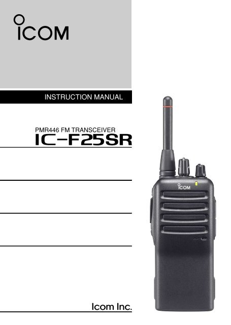
INSTRUCTION MANUAL<br />
PMR446 FM TRANSCEIVER<br />
i<strong>F25SR</strong>
IMPORTANT<br />
READ ALL INSTRUCTIONS carefully and completely before<br />
using the transceiver.<br />
SAVE THIS INSTRUCTION MANUAL— This instruction<br />
manual contains important operating instructions for the <strong>IC</strong>-<br />
<strong>F25SR</strong> PMR446 FM TRANSCEIVER.<br />
EXPL<strong>IC</strong>IT DEFINITIONS<br />
WORD<br />
RWARNING<br />
CAUTION<br />
NOTE<br />
DEFINITION<br />
Personal injury, fire hazard or electric shock<br />
may occur.<br />
Equipment damage may occur.<br />
If disregarded, inconvenience only. No risk<br />
of personal injury, fire or electric shock.<br />
i<br />
<strong>Icom</strong>, <strong>Icom</strong> Inc. and the logo are registered trademarks of <strong>Icom</strong> Incorporated<br />
(Japan) in the United States, the United Kingdom, Germany, France, Spain,<br />
Russia and/or other countries.<br />
All other products or brands are registered trademarks or trademarks of their respective<br />
holders.
PRECAUTIONS<br />
R CAUTION! NEVER hold the transceiver so that the antenna<br />
is very close to, or touching exposed parts of the body, especially<br />
the face or eyes, while transmitting. The transceiver will<br />
perform best if the microphone is 5 to 10 cm away from the lips and<br />
the transceiver is vertical.<br />
R CAUTION! NEVER operate the transceiver with a headset<br />
or other audio accessories at high volume levels.<br />
R CAUTION! NEVER short the terminals of the battery<br />
pack.<br />
DO NOT push [PTT] when not actually desiring to transmit.<br />
AVOID using or placing the transceiver in direct sunlight or in<br />
areas with temperatures below –25°C or above +55°C.<br />
The basic operations, transmission and reception of the transceiver<br />
are guaranteed within the specified operating temperature range.<br />
DO NOT modify the transceiver for any reason.<br />
Optional unit installation should be done at an authorized <strong>Icom</strong> service<br />
center only.<br />
KEEP the transceiver from heavy rain, and never immerse it in<br />
the water. The transceiver construction is water resistant, not waterproof.<br />
The use of non-<strong>Icom</strong> battery packs/chargers may impair transceiver<br />
performance and invalidate the warranty.<br />
ii
DOC<br />
CE versions of the <strong>IC</strong>-<strong>F25SR</strong> which display the<br />
“CE” symbol on the serial number seal, comply with<br />
the essential requirements of the European Radio<br />
and Telecommunication Terminal Directive<br />
1999/5/EC.<br />
DECLARATION<br />
OF CONFORMITY<br />
We <strong>Icom</strong> Inc. Japan<br />
1-1-32, Kamiminami, Hirano-ku<br />
Osaka 547-0003, Japan<br />
Declare on our sole responsibility that this equipment complies with the<br />
essential requirements of the Radio and Telecommunications Terminal<br />
Equipment Directive, 1999/5/EC, and that any applicable Essential Test<br />
Suite measurements have been performed.<br />
Kind of equipment:<br />
Type-designation:<br />
Version (where applicable):<br />
UHF PMR TRANSCEIVER<br />
iC- f25sr<br />
This compliance is based on conformity with the following harmonised<br />
standards, specifications or documents:<br />
i) EN 60950-1 2001<br />
ii) EN 300 296-2 (March 2001)<br />
iii) EN 301 489-1 V1.4.1 (August 2002)<br />
iv) EN 301 489-5 V1.3.1 (August 2002)<br />
v)<br />
vi)<br />
vii)<br />
Place and date of issue<br />
Authorized representative name<br />
H. Ikegami<br />
General Manager<br />
Signature<br />
0168<br />
14th Jul. 2006<br />
iii
TABLE OF CONTENTS<br />
IMPORTANT …………………………………………………………………… i<br />
EXPL<strong>IC</strong>IT DEFINITIONS ……………………………………………………… i<br />
PRECAUTIONS ………………………………………………………………… ii<br />
DOC……………………………………………………………………………… iii<br />
TABLE OF CONTENTS ……………………………………………………… iv<br />
1 ACCESSORIES ………………………………………………………… 1–4<br />
‘ Supplied accessories …………………………………………………… 1<br />
‘ Accessory attachments ………………………………………………… 2<br />
2 PANEL DESCRIPTION ………………………………………………… 5–8<br />
‘ Front, top and side panels ……………………………………………… 5<br />
‘ LED indicator …………………………………………………………… 7<br />
‘ Programmable function keys …………………………………………… 8<br />
3 BAS<strong>IC</strong> OPERATION ………………………………………………… 9–17<br />
‘ Receiving and transmitting …………………………………………… 9<br />
‘ Setting the squelch level ……………………………………………… 11<br />
‘ Auto scan function …………………………………………………… 11<br />
‘ Battery type selection ………………………………………………… 12<br />
‘ Setting the group code number ……………………………………… 13<br />
‘ Find scan operation …………………………………………………… 17<br />
4 RINGER FUNCTION ………………………………………………… 18–20<br />
‘ Call-Ring operation …………………………………………………… 18<br />
‘ Smart-Ring operation ………………………………………………… 19<br />
5 OTHER FUNCTIONS………………………………………………… 21–23<br />
‘ Monitor audible function ……………………………………………… 21<br />
‘ Time-Out Timer ………………………………………………………… 21<br />
‘ Power save function …………………………………………………… 22<br />
‘ Low battery indication ………………………………………………… 22<br />
‘ Scrambler function……………………………………………………… 23<br />
‘ All reset function ……………………………………………………… 23<br />
6 BATTERY CHARGING ……………………………………………… 24–32<br />
‘ Caution ………………………………………………………………… 24<br />
‘ Battery chargers………………………………………………………… 27<br />
7 BATTERY CASE……………………………………………………… 33–34<br />
‘ Optional battery case (BP-240) ……………………………………… 33<br />
8 SWIVEL BELT CLIP ………………………………………………… 35–38<br />
‘ MB-93 contents ………………………………………………………… 35<br />
‘ Attaching ………………………………………………………………… 35<br />
‘ Detaching ……………………………………………………………… 37<br />
9 OPTIONS ……………………………………………………………… 39–40<br />
10 SPECIF<strong>IC</strong>ATIONS …………………………………………………… 41–42<br />
iv
1 ACCESSORIES<br />
■ Supplied accessories<br />
Battery pack<br />
Battery charger<br />
Belt clip<br />
Jack cover<br />
(with screws)<br />
AC adapter* 1<br />
(for the battery charger)<br />
Unit cover* 2<br />
(double-sided tape)<br />
* 1<br />
* 2<br />
Depends on version.<br />
Use the unit cover as a spare.<br />
Ask your dealer for details.<br />
1
■ Accessory attachments<br />
ACCESSORIES<br />
ï Battery pack<br />
To attach the battery pack:<br />
Slide the battery pack in the direction of the arrow (q), then lock it<br />
with the battery release button.<br />
• Slide the battery pack until the battery release button makes a ‘click’<br />
sound.<br />
1<br />
1<br />
To release the battery pack:<br />
Push the battery release button in the direction of the arrow (w).<br />
Then slide the battery pack in the direction opposite to the arrow<br />
(q).<br />
NEVER release or attach the battery pack when the transceiver<br />
is wet or soiled. This may result in water or dust getting into the<br />
transceiver/battery pack and may result in the transceiver being<br />
damaged.<br />
q<br />
w<br />
Battery release button<br />
2
1 ACCESSORIES<br />
D Belt clip<br />
To attach the belt clip:<br />
q Release the battery pack if it is attached.<br />
w Slide the belt clip in the direction of the arrow until the belt clip is<br />
locked and makes a ‘click’ sound.<br />
To detach the belt clip:<br />
q Release the battery pack if it is attached.<br />
w Pinch to lift the clip (q), and slide the belt clip in the direction of<br />
arrow (w).<br />
q<br />
w<br />
3
ACCESSORIES<br />
ï Jack cover<br />
Attach the jack cover when the optional speaker-microphone or<br />
headset is not used.<br />
1<br />
1<br />
To attach the jack cover:<br />
q Attach the jack cover to the<br />
[M<strong>IC</strong>/SP] jack.<br />
w Tighten the screws using a<br />
Phillips screwdriver.<br />
To detach the jack cover:<br />
q Unscrew the screws using a<br />
Phillips screwdriver.<br />
w Detach the jack cover for the<br />
optional speaker-microphone<br />
or headset connection.<br />
[M<strong>IC</strong>/SP] jack<br />
w<br />
q<br />
Jack cover<br />
q<br />
q<br />
w<br />
CAUTION!: Use the supplied screws only.<br />
4
2 PANEL DESCRIPTION<br />
■ Front, top and side panels<br />
q<br />
Antenna<br />
u<br />
y<br />
t<br />
w<br />
e<br />
Speaker<br />
r<br />
Microphone<br />
q CHANNEL SELECTOR [CH selector]<br />
Rotate to select the pre-programmed memory channels.<br />
w VOLUME CONTROL [VOL]<br />
Rotate to turn the power ON/OFF and adjust the audio level.<br />
5
PANEL DESCRIPTION<br />
2<br />
e LED IND<strong>IC</strong>ATOR (p. 7)<br />
➥ Lights red while transmitting.<br />
➥ Lights green while receiving a signal, or when the squelch is<br />
open.<br />
➥ Blinks orange after transmitting/receiving a Smart-Ring call.<br />
➥ Blinks green to indicate the low battery condition.<br />
2<br />
r EXTERNAL M<strong>IC</strong>ROPHONE/SPEAKER JACK [M<strong>IC</strong>/SP]<br />
Connect an optional speaker-microphone or headset.<br />
Jack cover<br />
NOTE: Attach the jack cover<br />
when optional equipment is<br />
not used.<br />
See page 4 for details.<br />
t PROGRAMMABLE KEY [Lower]<br />
The desired function can be assigned. (p. 8)<br />
y PTT SWITCH [PTT]<br />
Push and hold to transmit; release to receive.<br />
u PROGRAMMABLE KEY [Upper]<br />
The desired function can be assigned. (p. 8)<br />
6
2 PANEL DESCRIPTION<br />
‘ LED indicator<br />
The LED indicator indicates the information as<br />
follows;<br />
(Ref.; R=Red, G=Green, O=Orange)<br />
• TX: Turns Red while transmitting a signal.<br />
R (O)*<br />
• RX: Turns Green while receiving a signal.<br />
G<br />
• Call LED (Blink): Transmitting or receiving the Smart-Ring.<br />
O O<br />
• Auto/Find scan: Blinks while Auto/Find scan is activated.<br />
G<br />
G<br />
• Low BATT1: You should charge the battery. (blinks slowly)<br />
G G<br />
• Low BATT2: You must charge the battery. (blinks fast)<br />
G G G G<br />
• TX low BATT1: Low BATT1 was detected during TX mode.<br />
R<br />
R<br />
• TX low BATT2: Low BATT2 was detected during TX mode.<br />
R R R R<br />
* During the alkaline battery operation.<br />
7
PANEL DESCRIPTION<br />
‘ Programmable function keys<br />
The desired key function can be assigned to [Upper] and [Lower]<br />
in following way.<br />
2<br />
2<br />
q Turn power OFF in advance.<br />
w Rotate [CH selector] to select channel 16.<br />
e Rotate [VOL] to turn power ON while pushing and holding the<br />
desired key, [Upper] or [Lower], to be assigned.<br />
• The beep is emitted depending on the selected function as below.<br />
[Smart Ring/Ringer]<br />
[Moni]<br />
[Scrambler]<br />
[Null]<br />
1 high beep is emitted.<br />
2 high beeps are emitted.<br />
3 high beeps are emitted.<br />
1 high beep is emitted for 1 sec.<br />
r Turn power OFF.<br />
t Repeat steps e and r until the desired key function is assigned.<br />
NULL KEY<br />
No function.<br />
SMART RING/RINGER KEY<br />
➥ Push to send a Smart-Ring call.<br />
➥ Push and hold for 1 sec. to send a Call-Ring.<br />
MONITOR KEY<br />
➥ Push to mute the CTCSS (or DTCS) squelch mute.<br />
➥ Push and hold for 1 sec. to release the CTCSS (or DTCS)<br />
squelch mute.<br />
➥ Open any squelch/deactivate any mute while pushing and holding<br />
this key.<br />
VO<strong>IC</strong>E SCRAMBLER FUNCTION KEY<br />
➥ Push to turn the voice scrambler function OFF.<br />
➥ Push and hold for 1 sec. to turn the voice scrambler function ON.<br />
8
3 BAS<strong>IC</strong> OPERATION<br />
■ Receiving and transmitting<br />
Prior to using the transceiver for the first time, the battery pack<br />
must be fully charged for optimum life and operation. (P. 24)<br />
Receiving:<br />
q Rotate [VOL] clockwise to turn power<br />
[CH selector]<br />
ON.<br />
w Rotate [CH selector] to select the desired<br />
operating channel.<br />
[VOL]<br />
• Set your group code number if required.<br />
(pgs. 13–16)<br />
• Scan starts automatically when channel<br />
16 is selected. (p. 11)<br />
e Listen for a transmission and adjust<br />
[VOL] to a comfortable listening level.<br />
• The LED indicator turns green, when<br />
the received signal contains the same Microphone<br />
CTCSS tone or DTCS code.<br />
• When no transmission is heard, push<br />
and hold [MONI] while adjusting [VOL].<br />
r The transceiver is now set to receive desired calls on the selected<br />
channel.<br />
Transmitting:<br />
Wait for the channel to become clear to avoid interference.<br />
q While pushing and holding [PTT], speak into the microphone at<br />
a normal voice level.<br />
• The LED indicator turns red.<br />
w Release [PTT] to return to receive.<br />
9<br />
IMPORTANT!: To maximize the readability of your signal;<br />
1. Pause briefly after pushing [PTT].<br />
2. Hold the microphone 5 to 10 cm from your lips, then speak<br />
into the microphone at a normal voice level.
BAS<strong>IC</strong> OPERATION<br />
3<br />
D Frequency channel/CTCSS tone list (default)<br />
CH<br />
1<br />
2<br />
3<br />
4<br />
5<br />
6<br />
7<br />
8<br />
9<br />
10<br />
11<br />
12<br />
13<br />
14<br />
15<br />
16<br />
Frequency (MHz)* 1<br />
446.006250<br />
446.018750<br />
446.031250<br />
446.043750<br />
446.056250<br />
446.068750<br />
446.081250<br />
446.093750<br />
446.006250<br />
446.018750<br />
446.031250<br />
446.043750<br />
446.056250<br />
446.068750<br />
446.081250<br />
Auto Scan<br />
Tone (Hz)* 2<br />
No setting<br />
No setting<br />
No setting<br />
107.2<br />
110.9<br />
114.8<br />
118.8<br />
123.0<br />
127.3<br />
131.8<br />
136.5<br />
141.3<br />
146.2<br />
151.4<br />
156.7<br />
—<br />
3<br />
* 1 All operating channel frequencies cannot be changed.<br />
* 2 CTCSS tones can be programmed. You can use DTCS (Digital Tone<br />
Code Squelch) instead of CTCSS. (p. 15)<br />
10
3 BAS<strong>IC</strong> OPERATION<br />
‘ Setting the squelch level<br />
The squelch circuit mutes the received audio signal depending on<br />
the signal strength.<br />
q Turn power OFF in advance.<br />
w While pushing and holding [PTT]<br />
and [Lower], rotate [VOL] to<br />
turn power ON to enter the<br />
squelch adjustment mode.<br />
• A beep (Pi) is emitted.<br />
e Push [Upper] to increase the<br />
squelch level (tight squelch) or<br />
[Lower] to decrease the squelch<br />
level (loose squelch).<br />
• Squelch level will be fixed after 1<br />
sec.<br />
r Turn power OFF, then ON again.<br />
‘ Auto scan function<br />
[Upper]<br />
[PTT]<br />
[Lower]<br />
[VOL]<br />
Auto scan function proceeds from lower channel to higher channel<br />
numbers in sequence. Scanning searches for signals automatically<br />
and makes it easier to locate new stations for contact or listening<br />
purposes.<br />
[CH selector]<br />
11<br />
q Rotate [CH selector] to select<br />
channel 16.<br />
w Scan starts automatically.<br />
• The LED indicator blinks green<br />
slowly.<br />
• When receiving a signal, scan<br />
pauses until the signal disappears.
‘ Battery type selection<br />
BAS<strong>IC</strong> OPERATION<br />
3<br />
The battery type MUST be selected according to the type of battery<br />
attached when turning the transceiver ON.<br />
Ask your dealer for details.<br />
3<br />
NOTE: When the selected battery type is not matched to the attached<br />
battery, the transceiver does not work correctly.<br />
q Turn power OFF in advance.<br />
w While pushing and holding [PTT],<br />
rotate [VOL] to turn power ON.<br />
e After the transceiver is powered<br />
ON, you should hold [PTT] for 5<br />
sec. to toggle the attached battery<br />
type.<br />
• When the Lithium-Ion battery type is<br />
selected, a beep (Pi) is emitted after<br />
a 5 sec. count.<br />
• When the Alkaline battery type is<br />
selected, 2 beeps (PiPi) are emitted<br />
after a 5 sec. count.<br />
In this case, the LED indicator turns<br />
orange while transmitting a signal.<br />
[PTT]<br />
[VOL]<br />
12
3 BAS<strong>IC</strong> OPERATION<br />
‘ Setting the group code number<br />
D CTCSS tone setting<br />
The transceiver is equipped with 50 CTCSS tones and OFF. CTCSS<br />
operation provides communication with silent standby since you will<br />
only receive calls from group members using the same CTCSS tone.<br />
q Turn power OFF in advance.<br />
w While pushing and holding [PTT], [Upper] and [Lower], rotate<br />
[VOL] to turn the power ON.<br />
e Rotate [CH selector] to select the desired channel (1 to 15) that<br />
you want to assign the CTCSS tone to.<br />
r Push and hold [Upper] until a long beep is emitted.<br />
t Push [PTT] the necessary number of times to choose the 10<br />
digit of the desired CTCSS tone number (grey column) from the<br />
list at right.<br />
y Push [Upper].<br />
• Confirmation beep(s) is (are) emitted. (See the Confirmation beep<br />
list at right.)<br />
u Push [PTT] the necessary number of times to choose the 1 digit<br />
of the desired CTCSS tone number (grey column) from the list at<br />
right.<br />
i Push [Upper] to complete the setting.<br />
• Confirmation beep(s) is (are) emitted. (See the Confirmation beep<br />
list at right.)<br />
o Turn power OFF, then ON again.<br />
[Example]: Tone No. 28 (162.2 Hz) assignment to channel 4<br />
q Turn power OFF in advance.<br />
w While pushing and holding [PTT], [Upper] and [Lower], rotate<br />
[VOL] to turn the power ON.<br />
e Rotate [CH selector] to select channel 4, then push and hold<br />
[Upper] until a long beep is emitted.<br />
13
BAS<strong>IC</strong> OPERATION<br />
3<br />
r Push [PTT] twice to choose the 2 (10 digit) of the tone number<br />
28.<br />
t Push [Upper] (2 short beeps are emitted,) then push [PTT] eight<br />
times to choose the 8 (1 digit) of the tone number 28.<br />
y Push [Upper] to complete the setting.<br />
• A long beep and 3 short beeps are emitted.<br />
u Turn power OFF, then ON again.<br />
3<br />
• Available CTCSS tone list<br />
(Hz)<br />
No.<br />
01<br />
02<br />
03<br />
04<br />
05<br />
06<br />
07<br />
08<br />
09<br />
10<br />
Freq.<br />
67.0<br />
69.3<br />
71.9<br />
74.4<br />
77.0<br />
79.7<br />
82.5<br />
85.4<br />
88.5<br />
91.5<br />
No.<br />
11<br />
12<br />
13<br />
14<br />
15<br />
16<br />
17<br />
18<br />
19<br />
20<br />
Freq.<br />
94.8<br />
97.4<br />
100.0<br />
103.5<br />
107.2<br />
110.9<br />
114.8<br />
118.8<br />
123.0<br />
127.3<br />
No.<br />
21<br />
22<br />
23<br />
24<br />
25<br />
26<br />
27<br />
28<br />
29<br />
30<br />
Freq.<br />
131.8<br />
136.5<br />
141.3<br />
146.2<br />
151.4<br />
156.7<br />
159.8<br />
162.2<br />
165.5<br />
167.9<br />
No.<br />
31<br />
32<br />
33<br />
34<br />
35<br />
36<br />
37<br />
38<br />
39<br />
40<br />
Freq.<br />
171.3<br />
173.8<br />
177.3<br />
179.9<br />
183.5<br />
186.2<br />
189.9<br />
192.8<br />
196.6<br />
199.5<br />
No.<br />
41<br />
42<br />
43<br />
44<br />
45<br />
46<br />
47<br />
48<br />
49<br />
50<br />
00<br />
Freq.<br />
203.5<br />
206.5<br />
210.7<br />
218.1<br />
225.7<br />
229.1<br />
233.6<br />
241.8<br />
250.3<br />
254.1<br />
OFF<br />
• Confirmation beep list<br />
Push [PTT]<br />
Confirmation beep<br />
Push [PTT]<br />
Confirmation beep<br />
No push<br />
●<br />
5 (Fifth)<br />
●●●●●<br />
1 (Once)<br />
●<br />
6 (Sixth)<br />
●<br />
2 (Twice)<br />
●●<br />
7 (Seventh)<br />
●●<br />
3 (Third)<br />
●●●<br />
8 (Eighth)<br />
●●●<br />
4 (Fourth)<br />
●●●●<br />
9 (Ninth)<br />
●●●●<br />
● : Short beep<br />
: Long beep<br />
14
3 BAS<strong>IC</strong> OPERATION<br />
D DTCS code setting<br />
This transceiver is equipped with 84 DTCS codes and OFF.<br />
DTCS operation provides communication with silent standby since<br />
you will only receive calls from group members using the same<br />
DTCS code.<br />
q Turn power OFF in advance.<br />
w While pushing and holding [PTT], [Upper] and [Lower], rotate<br />
[VOL] to turn the power ON.<br />
e Rotate [CH selector] to select the desired channel (1 to 15) that<br />
you want to assign the DTCS code to.<br />
r Push and hold [Lower] until a long beep is emitted.<br />
t Push [PTT] the necessary number of times to choose the 10<br />
digit of the desired DTCS code number (grey column) from the<br />
list at right.<br />
y Push [Upper].<br />
• Confirmation beep(s) is (are) emitted. (See the Confirmation beep<br />
list on p. 14.)<br />
u Push [PTT] the necessary number of times to choose the 1 digit<br />
of the desired DTCS code number (grey column) from the list at<br />
right.<br />
i Push [Upper].<br />
• Confirmation beep(s) is (are) emitted. (See the Confirmation beep<br />
list on p. 14.)<br />
o If you want to use Inverse mode, push [PTT] once more.<br />
*You can skip this step, if you want to use Normal mode.<br />
!0Push [Upper] to complete the setting.<br />
• A short beep is emitted.<br />
!1Turn power OFF, then ON again.<br />
15<br />
[Example]: Code No. 16 (114) with Inverse mode assignment to<br />
channel 5<br />
q Turn power OFF in advance.<br />
w While pushing and holding [PTT], [Upper] and [Lower], rotate<br />
[VOL] to turn the power ON.
BAS<strong>IC</strong> OPERATION<br />
3<br />
e Rotate [CH selector] to select channel 5, then push and hold<br />
[Lower] until a long beep is emitted.<br />
r Push [PTT] once to choose the 1 (10 digit) of the code number 16.<br />
t Push [Upper] (a short beep is emitted,) then push [PTT] six times<br />
to choose the 6 (1 digit) of the code number 16.<br />
y Push [Upper].<br />
• A long beep and a short beep are emitted.<br />
u Push [PTT] once more, to use Inverse mode.<br />
i Push [Upper] to complete the setting.<br />
• A short beep is emitted.<br />
o Turn the power OFF, and then ON again.<br />
3<br />
• Available DTCS code list<br />
No.<br />
01<br />
02<br />
03<br />
04<br />
05<br />
06<br />
07<br />
08<br />
09<br />
10<br />
51<br />
52<br />
53<br />
54<br />
55<br />
56<br />
57<br />
58<br />
59<br />
60<br />
Code<br />
023<br />
025<br />
026<br />
031<br />
032<br />
036<br />
043<br />
047<br />
051<br />
054<br />
371<br />
411<br />
412<br />
413<br />
423<br />
431<br />
432<br />
445<br />
464<br />
465<br />
No.<br />
11<br />
12<br />
13<br />
14<br />
15<br />
16<br />
17<br />
18<br />
19<br />
20<br />
61<br />
62<br />
63<br />
64<br />
65<br />
66<br />
67<br />
68<br />
69<br />
70<br />
Code<br />
065<br />
071<br />
072<br />
073<br />
074<br />
114<br />
115<br />
116<br />
125<br />
131<br />
466<br />
503<br />
506<br />
516<br />
532<br />
546<br />
565<br />
606<br />
612<br />
624<br />
No.<br />
21<br />
22<br />
23<br />
24<br />
25<br />
26<br />
27<br />
28<br />
29<br />
30<br />
71<br />
72<br />
73<br />
74<br />
75<br />
76<br />
77<br />
78<br />
79<br />
80<br />
Code<br />
132<br />
134<br />
143<br />
152<br />
155<br />
156<br />
162<br />
165<br />
172<br />
174<br />
627<br />
631<br />
632<br />
654<br />
662<br />
664<br />
703<br />
712<br />
723<br />
731<br />
No.<br />
31<br />
32<br />
33<br />
34<br />
35<br />
36<br />
37<br />
38<br />
39<br />
40<br />
81<br />
82<br />
83<br />
84<br />
00<br />
Code<br />
205<br />
223<br />
226<br />
243<br />
244<br />
245<br />
251<br />
261<br />
263<br />
265<br />
732<br />
734<br />
743<br />
754<br />
OFF<br />
No.<br />
41<br />
42<br />
43<br />
44<br />
45<br />
46<br />
47<br />
48<br />
49<br />
50<br />
Code<br />
271<br />
306<br />
311<br />
315<br />
331<br />
343<br />
346<br />
351<br />
364<br />
365<br />
16
3 BAS<strong>IC</strong> OPERATION<br />
‘ Find scan operation<br />
This transceiver can detect the CTCSS tone and DTCS code* in<br />
the received signal. By monitoring a signal that is being transmitted<br />
from the other station, you can determine the tone frequency or<br />
DTCS code* required to communicate with them.<br />
This function is very useful when you are going to communicate<br />
with unknown CTCSS tone or DTCS code* stations.<br />
Scans all of the CTCSS tone and DTCS code*, then stops when a<br />
matched tone or code* is detected.<br />
q Turn power OFF in advance.<br />
w While pushing and holding [Upper] and [Lower], rotate [VOL] to<br />
turn power ON.<br />
Do not select channel 16 before turning power ON.<br />
e Rotate [CH selector] to select the desired channel (1 to 15) that<br />
you want to assign the CTCSS tone or DTCS code* to.<br />
r Push and hold [Upper] for 1 sec. to start scan.<br />
• The LED indicator blinks green slowly.<br />
• Push [Upper] to stop the scan.<br />
t The scan pauses when the matched tone or code* is detected.<br />
• Push [Upper] to determine the detected tone or code* number, and<br />
stop the scan.<br />
• Scan resumes 3 sec. after the signal disappears.<br />
y Turn power OFF, then ON again.<br />
Even if the scan is stopped with pushing [Upper], scan resumes<br />
after pushing and holding [Upper].<br />
* Depends on the pre-setting.<br />
17
RINGER FUNCTION<br />
‘ Call-Ring operation<br />
4<br />
Sends the pre-selected ring tone to your group members.<br />
D Select the Call-Ring melody<br />
q Turn power OFF in advance.<br />
w While pushing and holding [PTT]<br />
and [Upper], rotate [VOL] to<br />
turn power ON.<br />
• A sample melody is emitted.<br />
e Rotate [CH selector] to select<br />
the ringer melody.<br />
r Turn power OFF to determine<br />
the melody.<br />
[Upper]<br />
[PTT]<br />
[CH selector]<br />
[VOL]<br />
3<br />
4<br />
D Call your group member with Call-Ring melody<br />
q Set the same operating channel and CTCSS tone for all of your<br />
group transceivers. (p. 13)<br />
w Pushing and holding [Smart Ring/Ringer] for 1 sec. to send the<br />
pre-selected ring tone to your group member.<br />
• The ring tone is emitted while [Smart Ring/Ringer] is pushed and<br />
held.<br />
• The same ring tone comes from your group station’s speaker.<br />
18
4 RINGER FUNCTION<br />
‘ Smart-Ring operation<br />
The ring function has an answer back feature. This allows you to<br />
confirm whether or not a call has reached to the member of your<br />
group even if the operator is temporarily away from the transceiver.<br />
D Smart-Ring operation<br />
q Set the same operating channel and CTCSS tone code for all of<br />
your group transceivers. (p. 13)<br />
w Push [Smart Ring/Ringer] to send the Smart-Ring call.<br />
• When a member of your group station answers your call, the transceiver<br />
emits beep tones for every 10 sec.* and the LED indicator<br />
blinks with an orange color.<br />
*Depends on the pre-setting.<br />
• Push [MONI] to cancel the Ringer beep and the LED blinking.<br />
• When no answer comes back, the transceiver emits short failure<br />
beep tones.<br />
e Push [PTT] to answer the call and to stop the beeps and blinking.<br />
NOTE: This function is available only when the called station<br />
has use the same CTCSS tone code and the same operating<br />
channels as you.<br />
19
RINGER FUNCTION<br />
4<br />
Push [Smart Ring/Ringer]<br />
4<br />
Answer back (automatic)<br />
Piro Piro<br />
Piro Piro<br />
Communication<br />
20
5 OTHER FUNCTIONS<br />
‘ Monitor audible function<br />
The monitor function allows you to open the transceiver’s squelch<br />
manually to check whether a channel is busy or not. The transceiver<br />
has 2 conditions for receive standby.<br />
• Audible condition<br />
All signals are<br />
received<br />
This condition mutes audio ONLY when no<br />
carrier is present. You can receive (or monitor)<br />
any signals on a channel.<br />
• Push and hold [MONI] to release the CTCSS<br />
or DTCS tone squelch mute.<br />
Any received audio is emitted while pushing<br />
and holding [MONI].<br />
• Inaudible condition<br />
This condition mutes ALL signals except<br />
those directed to you. Therefore you should<br />
check a channel’s condition (busy or not)<br />
with the monitor function before transmitting.<br />
• Push [MONI] to mute the CTCSS or DTCS<br />
tone squelch mute.<br />
Only signals containing<br />
the proper<br />
tone are received.<br />
‘ Time-Out Timer<br />
The transceiver has a time-out timer function. This function prevents<br />
continuous, extend transmissions. This timer automatically<br />
turns a transmission OFF 3 min. after it starts.<br />
21
‘ Power save function<br />
OTHER FUNCTIONS<br />
5<br />
The power save function reduces the current drain to conserve battery<br />
power.<br />
• The power save function is automatically turned ON when no operation<br />
is performed or no signal is received for 5 sec.<br />
‘ Low battery indication<br />
5<br />
The LED indicator indicates 4 levels of the “Low battery” condition<br />
as follows.<br />
If the “Low battery” warning occurs during operation, please charge<br />
or replace the battery.<br />
[Blink patterns]<br />
• Low BATT1: You should charge the battery. (blinks slowly)<br />
• Low BATT2: You must charge the battery. (blinks fast)<br />
G G G G<br />
• TX low BATT1: Low BATT1 was detected during TX mode.<br />
• TX low BATT2: Low BATT2 was detected during TX mode.<br />
R<br />
R R R R<br />
G<br />
R<br />
G<br />
In an extreme low temperature surroundings (around –20°C), the<br />
capacity of the battery may exhaust quickly (especially Alkaline<br />
batteries). In such a case, we recommend to charge the battery<br />
or replace the batteries, when the “Low Battery” indication occurs<br />
during operation.<br />
22
5 OTHER FUNCTIONS<br />
■ Scrambler function<br />
The voice scrambler function provides private communication between<br />
stations. The optional UT-110 (Rolling) or UT-109 (Nonrolling)<br />
is required. Ask your dealer for details.<br />
q Push and hold [Scrambler] for 1 sec, to turn the scrambler function<br />
ON.<br />
• A short beep and a long beep are emitted.<br />
w Push [Scrambler] to turn the scrambler function OFF.<br />
• A short beep is emitted.<br />
■ All reset function<br />
Reset the CPU before operating the transceiver for the first time,<br />
or if the internal CPU malfunctions, to clear and return all programmed<br />
contents to their default settings.<br />
q Turn power OFF in advance.<br />
w Rotate [CH selector] to select channel 16.<br />
e While pushing and holding [PTT], [Upper] and [Lower], rotate<br />
[VOL] to turn power ON.<br />
r After the transceiver is powered ON, you should hold [PTT],<br />
[Upper] and [Lower] for 5 sec. to reset the CPU.<br />
• A long beep is emitted.<br />
t Turn power OFF.<br />
CAUTION: Resetting the CPU returns all programmed contents<br />
to their default settings.<br />
23
BATTERY CHARGING<br />
■ Caution<br />
6<br />
Misuse of Lithium-Ion batteries may result in the following<br />
hazards: smoke, fire, or the battery may rupture. Misuse can<br />
also cause damage to the battery or degradation of battery<br />
performance.<br />
R DANGER! Use and charge only specified <strong>Icom</strong> battery packs<br />
with <strong>Icom</strong> radios or <strong>Icom</strong> charger. Only <strong>Icom</strong> battery packs are<br />
tested and approved for use and charge with <strong>Icom</strong> radios or <strong>Icom</strong><br />
charger. Using third-party or counterfeit battery packs or charger<br />
may cause smoke, fire, or cause the battery to burst.<br />
D Battery caution<br />
R DANGER! DO NOT hammer or otherwise impact the battery. Do<br />
not use the battery if it has been severely impacted or dropped, or if<br />
the battery has been subjected to heavy pressure. Battery damage<br />
may not be visible on the outside of the case. Even if the surface of<br />
the battery does not show cracks or any other damage, the cells inside<br />
the battery may rupture or catch fire.<br />
R DANGER! NEVER use or leave battery packs in areas with temperatures<br />
above +60˚C. High temperature buildup in the battery,<br />
such as could occur near fires or stoves, inside a sun heated car, or<br />
in direct sunlight may cause the battery to rupture or catch fire. Excessive<br />
temperatures may also degrade battery performance or<br />
shorten battery life.<br />
R DANGER! DO NOT expose the battery to rain, snow, seawater,<br />
or any other liquids. Do not charge or use a wet battery. If the battery<br />
gets wet, be sure to wipe it dry before using. The battery is not<br />
waterproof.<br />
R DANGER! NEVER incinerate used battery packs since internal<br />
battery gas may cause them to rupture, or may cause an explosion.<br />
5<br />
6<br />
24
6 BATTERY CHARGING<br />
R DANGER! NEVER solder the battery terminals or NEVER modify<br />
the battery pack. This may cause heat generation, and the battery<br />
may rupture, emit smoke or catch fire.<br />
R DANGER! Use the battery only with the transceiver for which it<br />
is specified. Never use a battery with any other equipment, or for<br />
any purpose that is not specified in this instruction manual.<br />
R DANGER! If fluid from inside the battery gets in your eyes, blindness<br />
can result. Rinse your eyes with clean water, without rubbing<br />
them, and see a doctor immediately.<br />
WARNING! Immediately stop using the battery if it emits an abnormal<br />
odor, heats up, or is discolored or deformed. If any of these<br />
conditions occur, contact your <strong>Icom</strong> dealer or distributor.<br />
WARNING! Immediately wash, using clean water, any part of the<br />
body that comes into contact with fluid from inside the battery.<br />
WARNING! NEVER put the battery in a microwave oven, highpressure<br />
container, or in an induction heating cooker. This could<br />
cause a fire, overheating, or cause the battery to rupture.<br />
CAUTION! Always use the battery within the specified temperature<br />
range for the transceiver (–25˚C to +55˚C) and the battery itself<br />
(–20˚C to +60˚C). Using the battery out of its specified temperature<br />
range will reduce the battery’s performance and battery life. Please<br />
note that the specified temperature range of the battery may exceed<br />
that of the transceiver. In such cases, the transceiver may not<br />
work properly because it is out of its operating temperature range.<br />
CAUTION! Shorter battery life could occur if the battery is left fully<br />
charged, completely discharged, or in an excessive temperature<br />
environment (above +45˚C) for an extended period of time. If the<br />
battery must be left unused for a long time, it must be detached<br />
from the radio after discharging. You may use the battery until the<br />
remaining capacity is about half, then keep it safely in a cool dry<br />
place with the temperature between –20˚C to +25˚C.<br />
25
D Charging caution<br />
BATTERY CHARGING<br />
R DANGER! NEVER charge the battery pack in areas with extremely<br />
high temperatures, such as near fires or stoves, inside a<br />
sun heated car, or in direct sunlight. In such environments, the<br />
safety/protection circuit in the battery will activate, causing the battery<br />
to stop charging.<br />
WARNING! DO NOT charge or leave the battery in the battery<br />
charger beyond the specified time for charging. If the battery is not<br />
completely charged by the specified time, stop charging and remove<br />
the battery from the battery charger. Continuing to charge the<br />
battery beyond the specified time limit may cause a fire, overheating,<br />
or the battery may rupture.<br />
WARNING! NEVER insert the transceiver (battery attached to the<br />
transceiver) into the charger if it is wet or soiled. This could corrode<br />
the battery charger terminals or damage the charger. The charger is<br />
not waterproof.<br />
CAUTION! DO NOT charge the battery outside of the specified<br />
temperature range: BC-160 and BC-171 (0˚C to +45˚C). <strong>Icom</strong> recommends<br />
charging the battery at +20˚C. The battery may heat up<br />
or rupture if charged out of the specified temperature range. Additionally,<br />
battery performance or battery life may be reduced.<br />
6<br />
6<br />
26
6 BATTERY CHARGING<br />
■ Battery chargers<br />
D Rapid charging with the BC-160<br />
The BC-160 provides rapid charging of the optional Li-Ion battery<br />
pack. Charging period: Approx. 3 hours (with BP-232N)<br />
The following items are additionally required:<br />
• An AC adapter (may be supplied depending on version) or the DC<br />
power cable (OPC-515L/CP-17L) is additionally required.<br />
AC adapter Battery pack<br />
(Not supplied with<br />
some versions.)<br />
Turn power OFF<br />
Transceiver<br />
Optional OPC-515L<br />
(for 13.8 V power<br />
source) or CP-17L<br />
(for 12 V cigarette<br />
lighter socket) can<br />
be used instead of<br />
the AC adapter.<br />
27
BATTERY CHARGING<br />
6<br />
D Regular charging with the BC-171<br />
The BC-171 provides regular charging of the optional Li-Ion battery<br />
pack. Charging period: Approx. 10 hours (with BP-232N)<br />
The following items are additionally required:<br />
• An AC adapter (may be supplied depending on version) or the DC<br />
power cable (OPC-515L/CP-17L) is additionally required.<br />
AC adapter<br />
(Not supplied with<br />
some versions.)<br />
Battery pack<br />
Turn power OFF<br />
6<br />
Transceiver<br />
Optional OPC-515L<br />
(for 13.8 V power<br />
source) or CP-17L<br />
(for 12 V cigarette<br />
lighter socket) can<br />
be used instead of<br />
the AC adapter.<br />
28
6 BATTERY CHARGING<br />
ï AD-106 installation<br />
q Install the AD-106 desktop charger adapter into the holder space<br />
of the BC-119N/BC-121N.<br />
AD-106<br />
Connectors<br />
Plugs<br />
w Connect the plugs of the BC-119N/BC-121N to the AD-106 with<br />
the connector, then install the adapter into the charger with the<br />
supplied screws.<br />
Screws are supplied<br />
with the<br />
charger adapter.<br />
29
BATTERY CHARGING<br />
D Rapid charging with the BC-119N+AD-106<br />
The optional BC-119N provides rapid charging of the Li-Ion battery<br />
packs. Charging period: Approx. 3 hours (with BP-232N)<br />
6<br />
The following items are additionally required:<br />
• An AD-106 charger adapter<br />
• An AC adapter (may be supplied with the BC-119N depending on<br />
version) or the DC power cable (OPC-515L/CP-17L).<br />
Transceiver<br />
Turn power OFF<br />
6<br />
Battery pack<br />
AC adapter<br />
(Not supplied with<br />
some versions.)<br />
Optional OPC-515L<br />
(for 13.8 V power<br />
source) or CP-17L<br />
(for 12 V cigarette<br />
lighter socket) can<br />
be used instead of<br />
the AC adapter.<br />
The AD-106<br />
charger adapter<br />
is installed in the<br />
BC-119N.<br />
30
6 BATTERY CHARGING<br />
D Rapid charging with the BC-121N+AD-106<br />
The optional BC-121N allows up to 6 battery packs to be charged<br />
simultaneously. Charging period: Approx. 3 hours (with BP-232N)<br />
The following items are additionally required.<br />
• Six AD-106 charger adapters<br />
• An AC adapter (BC-157) or the DC power cable (OPC-656)<br />
Battery pack<br />
Transceiver<br />
Turn power OFF<br />
AC adapter<br />
(Purchased<br />
separately)<br />
AD-106 charger<br />
adapters are installed<br />
in each slot.<br />
DC power cable<br />
(OPC-656)<br />
(Connect with the<br />
DC power supply;<br />
13.8 V/at least 7 A)<br />
31
BATTERY CHARGING<br />
IMPORTANT!: Battery charging caution<br />
Ensure the guide lobs on the battery pack are correctly<br />
aligned with the guide rails inside the charger adapter. (This<br />
illustration is shown using the BC-160.)<br />
6<br />
6<br />
Lobs<br />
Guide rail<br />
32
7 BATTERY CASE<br />
■ Optional battery case (BP-240)<br />
When using the optional battery case, install 6 × AAA (LR03) size<br />
alkaline batteries as illustrated at right.<br />
q Unhook the battery cover release hook (q), and open the cover<br />
in the direction of the arrow (w). (Fig.1)<br />
w Then, install 6 × AAA (LR03) size alkaline batteries. (Fig.2)<br />
• Install the alkaline batteries only.<br />
• Be sure to observe the correct polarity.<br />
• Do not pin the ribbon under the batteries.<br />
e Fit the cover in the direction of the arrow (e), then close (r).<br />
Hook the battery cover release hook until it makes a ‘click’ sound<br />
(t). (Fig.3)<br />
CAUTION:<br />
• When installing batteries, make sure they are all the same<br />
brand, type and capacity. Also, do not mix new and old batteries<br />
together.<br />
• Keep battery contacts clean. It’s a good idea to clean battery<br />
terminals once a week.<br />
• Never incinerate used battery cells since internal battery gas<br />
may cause them to rupture.<br />
• Never expose a detached battery case to water. If the battery<br />
case gets wet, be sure to wipe it dry before using it.<br />
NOTE: When the optional battery case is attached, the battery<br />
type must be selected to “Alkaline battery operation” when turning<br />
the transceiver ON. (p. 12)<br />
33
BATTERY CASE<br />
7<br />
Fig.1<br />
w<br />
BP-240<br />
Fig.2<br />
q<br />
7<br />
Fig.3<br />
e<br />
r<br />
t<br />
34
8 SWIVEL BELT CLIP<br />
■ MB-93 contents<br />
Qty.<br />
q Belt clip …………………………………………………………… 1<br />
w Base clip …………………………………………………………… 1<br />
q<br />
w<br />
■ Attaching<br />
q Release the battery pack if it is attached. (p. 2)<br />
w Slide the base clip in the direction of the arrow until the base clip<br />
is locked and makes a ‘click’ sound.<br />
35
SWIVEL BELT CLIP<br />
e Clip the belt clip to a part of your belt. And insert the transceiver<br />
into the belt clip until the base clip is inserted fully into the groove.<br />
8<br />
8<br />
r Once the transceiver is locked in place, it swivels as illustrated<br />
below.<br />
Once the transceiver is locked in place,<br />
it will swivel 360 degrees.<br />
36
8 SWIVEL BELT CLIP<br />
■ Detaching<br />
q Turn the transceiver upside down in the direction of the arrow<br />
and pull out from the belt clip.<br />
37
SWIVEL BELT CLIP<br />
8<br />
w Release the battery pack if it is attached. (p. 2)<br />
e Pinch to lift the clip (q), and slide the base clip in the direction of<br />
the arrow (w).<br />
q<br />
w<br />
8<br />
CAUTION:<br />
HOLD THE TRANSCEIVER TIGHTLY, WHEN HANGING OR<br />
DETACHING THE TRANSCEIVER FROM THE BELT CLIP.<br />
Otherwise the transceiver may not be attached to the holder or<br />
swivel properly if the transceiver is accidentally dropped and the<br />
base clip is scratched or damaged.<br />
38
9 OPTIONS<br />
D BATTERY PACKS<br />
Battery pack<br />
Voltage Capacity Battery life* 1<br />
BP-230N<br />
7.4 V<br />
980 mAh<br />
13 hrs.<br />
BP-232N<br />
BP-240<br />
7.4 V<br />
2000 mAh<br />
Battery case for AAA<br />
(LR03) × 6 alkaline<br />
26.5 hrs.<br />
—* 2<br />
* 1 When the power save function is turned ON, and the operating<br />
periods are calculated under the following conditions;<br />
TX : RX : Standby = 5 : 5 : 90<br />
* 2 Operating period depends on the alkaline cells used.<br />
39<br />
D CHARGERS<br />
• BC-119N DESKTOP CHARGER + AD-106 CHARGER ADAPTER<br />
+ BC-145 AC ADAPTER<br />
For rapid charging of battery pack. An AC adapter is supplied with<br />
the charger depending on versions.<br />
Charging time: Approx. 3 hours when BP-232N is attached.<br />
• BC-121N MULTI-CHARGER + AD-106 CHARGER ADAPTER (6 pcs.)<br />
+ BC-157 AC ADAPTER<br />
For rapid charging of up to 6 battery packs (six AD-106’s are required)<br />
simultaneously. An AC adapter should be purchased separately.<br />
Charging time: Approx. 3 hours when BP-232N is attached.<br />
• BC-160 DESKTOP CHARGER + BC-145 AC ADAPTER<br />
For rapid charging of battery packs. An AC adapter is supplied<br />
with the charger depending on versions.<br />
Charging time: Approx. 3 hours when BP-232N is attached.<br />
• BC-171 DESKTOP CHARGER + BC-147 AC ADAPTER<br />
For regular charging of battery packs. We recommend that the<br />
BP-230N charging. An AC adapter is supplied with the charger depending<br />
on versions.<br />
Charging time: Approx. 10 hours when BP-232N is attached.<br />
Approx. 4 hours when BP-230N is attached.
OPTIONS<br />
D OPTIONAL UNITS<br />
• UT-109 (#01)/UT-110 (#01) SCRAMBLER UNITS<br />
Non-rolling type (UT-109)/Rolling type (UT-110) voice scrambler<br />
unit provides higher communication security.<br />
D BELT CLIPS<br />
• MB-93 SWIVEL BELT CLIP<br />
• MB-94 BELT CLIP<br />
Exclusive alligator-type belt clip.<br />
• MB-96N/96F LEATHER BELT HANGER<br />
9<br />
D DC CABLES<br />
• CP-17L CIGARETTE LIGHTER CABLE<br />
Allows charging of the battery pack through a 12 V cigarette<br />
lighter socket. (For BC-119N)<br />
• OPC-515L/OPC-656 DC POWER CABLES<br />
Allows charging of the battery pack using a 13.8 V power source<br />
instead of the AC adapter.<br />
OPC-515L : For BC-119N<br />
OPC-656 : For BC-121N<br />
9<br />
D OTHER OPTIONS<br />
• SP-13 EARPHONE<br />
Provides clear receive audio in noisy environments.<br />
• HM-153L EARPHONE-M<strong>IC</strong>ROPHONE<br />
• HM-158L/159L SPEAKER-M<strong>IC</strong>ROPHONE<br />
Combination speaker-microphone that provides convenient operation<br />
while hanging the transceiver from your belt.<br />
• HS-94/HS-95/HS-97 HEADSET + VS-1L VOX/PTT CASE<br />
HS-94 : Ear hook type HS-95: Neck-arm type<br />
HS-97 : Throat microphone<br />
VS-1L : VOX/PTT switch box for hands-free operation, etc.<br />
Some options may not be available in some countries. Please ask your<br />
dealer for details.<br />
40
10 SPECIF<strong>IC</strong>ATIONS<br />
D General<br />
• Frequency coverage<br />
• Mode<br />
• Current drain (at 7.2 V)<br />
• Power supply requirement<br />
• Frequency stability<br />
• Antenna impedance<br />
• Dimensions<br />
• Weight<br />
: 446.00625–446.09375 MHz<br />
: 8K50F3E (FM)<br />
: TX (at 0.5 W ERP) 0.4 A approx.<br />
Max. audio 300 mA max.<br />
: 7.2 V DC nominal*<br />
(negative ground)<br />
*Specified <strong>Icom</strong>’s battery pack only<br />
: ±2.5 ppm<br />
(–25°C to +55°C)<br />
: 50 Ω nominal<br />
: 53.0(W) × 195.0(H) × 38.0(D) mm<br />
(Fixed type antenna included)<br />
: Approx. 300 g (including BP-232N)<br />
D Transmitter<br />
• Output power<br />
• Modulation system<br />
• Max. frequency deviation<br />
• Spurious emissions<br />
• Adjacent channel power<br />
• External mic. connector<br />
: 0.5 W ERP<br />
: Variable reactance frequency<br />
modulation<br />
: ±2.5 kHz<br />
: 0.25 µW below 1 GHz<br />
1.00 µW above 1 GHz<br />
: 60 dB<br />
: 3-conductor 2.5 (d) mm/2.2 kΩ<br />
41
SPECIF<strong>IC</strong>ATIONS 10<br />
D Receiver<br />
• Receive system<br />
: Double conversion<br />
superheterodyne<br />
• Sensitivity (20 dB SINAD) : 26.5 dBµV/m<br />
• Squelch sensitivity<br />
: 26.5 dBµV/m (Threshold)<br />
• Intermodulation rejection ratio : 86.29 dBµV/m<br />
• Spurious response rejection ratio : 91.29 dBµV/m<br />
• Adjacent channel selectivity : 81.29 dBµV/m<br />
• Audio output power<br />
: 0.5 W (typical) at 5% distortion<br />
with an 8 Ω load<br />
0.6 W (typical) at 5% distortion<br />
with a 6 Ω load<br />
• External speaker connector : 2-conductor 3.5 (d) mm/8 Ω<br />
All stated specifications are subject to change without notice<br />
or obligation.<br />
10<br />
42
Intended Country of Use ><br />
GER<br />
AUT<br />
GBR<br />
IRL<br />
NOR<br />
FRA<br />
NED<br />
BEL<br />
LUX<br />
ESP<br />
POR<br />
ITA<br />
GRE<br />
SWE<br />
DEN<br />
FIN<br />
SUI<br />
A-6540D-1EU<br />
Printed in Japan<br />
© 2006 <strong>Icom</strong> Inc.<br />
1-1-32 Kamiminami, Hirano-ku, Osaka 547-0003, Japan









![VX-450 Series Spec Sheet [310 KB] - Vertex Standard](https://img.yumpu.com/24962253/1/184x260/vx-450-series-spec-sheet-310-kb-vertex-standard.jpg?quality=85)