Auralia - Instruction Manual.pdf - Nuova Simonelli
Auralia - Instruction Manual.pdf - Nuova Simonelli
Auralia - Instruction Manual.pdf - Nuova Simonelli

You also want an ePaper? Increase the reach of your titles
YUMPU automatically turns print PDFs into web optimized ePapers that Google loves.
Congratulations,<br />
By purchasing the you have made an excellent choice.<br />
The purchase of a professional espresso coffee-maker involves various elements of selection: the name of the manufacturing firm, the machine’s specific<br />
functions, its technical reliability, the option of immediate and suitable servicing, its price. You certainly evaluated all these factors and then made<br />
your choice: the model.<br />
We think you have made the best choice and after every coffee and cappuccino you will be able to assess this.<br />
You will see how practical, convenient and efficient working with is.<br />
If this is the first time you have bought a <strong>Nuova</strong> <strong>Simonelli</strong> coffee machine, welcome to high quality coffee-making; if you are already a customer of<br />
ours, we feel flattered by the trust you have shown us..<br />
Thanks of the preference.<br />
With best wishes,<br />
<strong>Nuova</strong> <strong>Simonelli</strong> s.r.l.<br />
ENGLISH<br />
Rel. 02 - 2004<br />
33
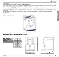
TECHNICAL CHARACTERISTICS<br />
F<br />
G<br />
E<br />
ENGLISH<br />
B<br />
A<br />
D<br />
C<br />
2 Groups 3 Groups 4 Groups<br />
NET WEIGHT 74 kg 136 lb 88kg 194 lb 104 kg 229 lb<br />
GROS WEIGHT 80kg 176 lb 98 kg 216 lb 120 kg 264 lb<br />
POWER 4500 W 4500 W 5000 W 5000 W 5000 W 5000 W<br />
DIMENSIONS A 780 mm A 30¹⁄₄” A 1010 mm A 39⁵⁄₁₆” A 1240 mm A 48⁵⁄₁₆”<br />
B 635 mm B 25” B 865 mm B 34” B 1095 mm B 43¹⁄₁₆”<br />
C 540 mm C 21¹⁄₈” C 540 mm C 21¹⁄₈” C 540 mm C 21¹⁄₈”<br />
D 315 mm D 12³⁄₁₆” D 315 mm D 12³⁄₁₆” D 315 mm D 12³⁄₁₆”<br />
E 510 mm E 20” E 510 mm E 20” E 510 mm E 20”<br />
F 135 mm F 5¹⁄₈” F 135 mm F 5¹⁄₈” F 135 mm F 5¹⁄₈”<br />
G 180 mm G 7¹⁄₁₆” G 180 mm G 7¹⁄₁₆” G 180 mm G 7¹⁄₁₆”<br />
34
INDEX<br />
TECHNICAL CHARACTERISTICS . . . . .34<br />
1. DESCRIPTION . . . . . . . . . . . . . . . . . . .37<br />
1.1 ACCESSORIES LIST . . . . . . . . . . . . . . . . . . . . . . . . .38<br />
2. SAFETY PRESCRIPTION . . . . . . . . . . .39<br />
3. TRANSPORT AND HANDLING . . . . . . .42<br />
3.1 MACHINE IDENTIFICATION . . . . . . . . . . . . . . . . . .42<br />
3.2 TRANSPORT . . . . . . . . . . . . . . . . . . . . . . . . . . . . . .42<br />
3.3 HANDLING . . . . . . . . . . . . . . . . . . . . . . . . . . . . . . .42<br />
4. INSTALLATION AND PRELIMINARY<br />
OPERATIONS . . . . . . . . . . . . . . . . . . . .43<br />
5. ADJUSTMENTS TO BE MADE BY A<br />
7.2 PROGRAMMING AURELIA VIP PLUS . . . . . . . . . . . .50<br />
7.3 PROGRAMMING AURELIA V . . . . . . . . . . . . . . . . . .55<br />
7.4 PROGRAMMING AURELIA ESSE . . . . . . . . . . . . . . .57<br />
8. CLEANING AND MAINTENANCE . . . . . .58<br />
8.1 SWITCHING OFF THE MACHINE . . . . . . . . . . . . . . .58<br />
8.2 CLEANING THE OUTSIDE OF THE MACHINE . . . . .58<br />
8.3 CLEANING STAINLESS COFFEE-HOLDERS . . . . . . .58<br />
8.4 CLEANING THE UNIT WITH THE AID OF THE<br />
BLIND FILTER . . . . . . . . . . . . . . . . . . . . . . . . . . . .58<br />
8.5 CLEANING FILTERS AND FILTER-HOLDERS . . . . . .58<br />
8.6 RESIN AND SOFTENER REGENERATION . . . . . . .59<br />
9. AURELIA PLUS MACHINE FUNCTION<br />
MESSAGES . . . . . . . . . . . . . . . . . . . . .60<br />
10. AURELIA V MACHINE FUNCTION<br />
MESSAGES . . . . . . . . . . . . . . . . . . . . .62<br />
ENGLISH<br />
QUALIFIED TECHNICIAN ONLY . . . . . .44<br />
5.1 FILLING BOILER MANUALLY . . . . . . . . . . . . . . . . .44<br />
5.2 PRESSOSTAT/PUMP ADJUSTMENT . . . . . . . . . . . .44<br />
5.3 HOT WATER ECONOMISER ADJUSTMENT . . . . . .45<br />
5.4 CLOCK BATTERY REPLACEMENT<br />
(ONLY FOR THE VIP PLUS VERSION) . . . . . . . . . . .45<br />
5.5 PUSH-BUTTON PANEL REPLACEMENT . . . . . . . . .45<br />
5.6 ELECTRONIC DISPLAYS . . . . . . . . . . . . . . . . . . . .45<br />
6. USE . . . . . . . . . . . . . . . . . . . . . . . . . .46<br />
6.1 TURNING THE MACHINE ON . . . . . . . . . . . . . . . . .46<br />
6.1.1 AURELIA VIP PLUS . . . . . . . . . . . . . . . . . . . . . . . .46<br />
6.1.2 AURELIA V/ESSE . . . . . . . . . . . . . . . . . . . . . . . . . .47<br />
6.1.3 AURELIA VIP-V/ESSE WITH ELECTRONIC DISPLAYS<br />
(OPTIONAL) . . . . . . . . . . . . . . . . . . . . . . . . . . . . . .47<br />
6.2 SELECTION CONFIGURATION . . . . . . . . . . . . . . . .48<br />
6.3 MAKING COFFEE . . . . . . . . . . . . . . . . . . . . . . . . . .48<br />
6.4 USING STEAM . . . . . . . . . . . . . . . . . . . . . . . . . . . .48<br />
6.5 MAKING CAPPUCCINO . . . . . . . . . . . . . . . . . . . . .49<br />
6.6 HOT WATER SELECTION . . . . . . . . . . . . . . . . . . . .49<br />
6.7 TIMED STEAM NOZZLE . . . . . . . . . . . . . . . . . . . . .49<br />
11. AURELIA S MACHINE FUNCTION<br />
MESSAGES . . . . . . . . . . . . . . . . . . . . .63<br />
ELECTRIC SYSTEM AURELIA S . . . . . .64<br />
ELECTRIC SYSTEM AURELIA PLUS<br />
Rel 3.xx . . . . . . . . . . . . . . . . . . . . . . . .65<br />
ELECTRIC SYSTEM AURELIA PLUS<br />
Rel 1.xx . . . . . . . . . . . . . . . . . . . . . . . .65<br />
ELECTRIC SYSTEM AURELIA V . . . . . .67<br />
PLUMBING SYSTEM . . . . . . . . . . . . . . .68<br />
7. PROGRAMMING . . . . . . . . . . . . . . . . . .50<br />
7.1 KEY . . . . . . . . . . . . . . . . . . . . . . . . . . . . . . . . . . . .50<br />
35
36<br />
ENGLISH
1. DESCRIPTION Vip Plus - V - Esse<br />
22<br />
1 2 3 4 5 6 7<br />
21<br />
8<br />
10<br />
9<br />
ENGLISH<br />
20<br />
11<br />
19 18 17 16 15 14 13 12<br />
Fig. 1<br />
KEY<br />
1 Steam knob<br />
2 Programming key (Vip Plus only)<br />
3 LCD Display (Vip Plus only)<br />
4 Functions buttons (Vip Plus only)<br />
5 Selections buttons<br />
6 Delivery unit buttons<br />
7 Electronic displays<br />
8 Steam knob<br />
9 Filter-holder<br />
10 Data plate<br />
11 <strong>Manual</strong> steam nozzle<br />
12 Delivery unit<br />
13 Main switch<br />
14 2 coffees spout<br />
15 1 coffee spout<br />
16 Automatic steam nozzle (optional in V and<br />
ESSE version)<br />
17 Optical level<br />
18 Pressure Gauge<br />
19 Adjustable foot<br />
20 <strong>Manual</strong> steam nozzle<br />
21 Hot water nozzle<br />
22 Electric cup-warmer (steam cup-warmer,<br />
optional)<br />
37
1.1 ACCESSORIES LIST<br />
A11<br />
A03<br />
A06<br />
A02<br />
A01<br />
ENGLISH<br />
A07<br />
A05<br />
A08<br />
A12<br />
A04<br />
A09<br />
A10<br />
Fig. 2<br />
CODE DESCRIPTION 2 GROUPS 3 GROUPS 4 GROUPS<br />
A01 Filling tube ³⁄₈” 1 1 1<br />
A02 Unit tub draining tube Ø 20 mm - l. 150 cm 1 1 1<br />
A03 Worktop draining tube Ø 25 mm - l. 150 cm 1 1 1<br />
A04 Filter-holder 3 4 5<br />
A05 Double filter 2 3 4<br />
A06 Single filter 1 1 1<br />
A07 Blind filter 1 1 1<br />
A08 Spring 3 4 5<br />
A09 Double delivery spout 2 3 4<br />
A10 Single delivery spout 1 1 1<br />
A11 Coffee presser 1 1 1<br />
A12 ‘U’ and ‘T’ keys (Plus model only) 1 1 1<br />
38
2. SAFETY PRESCRIPTION<br />
IlThis book is an integral and essential<br />
part of the product and must be<br />
☞<br />
given to the user. Read this book<br />
carefully. It provides important information<br />
concerning safety of installation,<br />
use and maintenance. Save it<br />
carefully for future reference.<br />
RISK OF POLLUTION<br />
After unpacking, make sure the<br />
☞ appliance is complete. In case of<br />
doubts, do not use the appliance, but<br />
consult a qualified technician.<br />
Packaging items which are potentially<br />
dangerous (plastic bags,<br />
polystyrene foam, nails, etc.) must be<br />
kept out of children’s reach and must<br />
not be disposed of in the environment.<br />
Fig. 3<br />
Before connecting the appliance<br />
☞ make sure the rating plate data correspond<br />
with the mains. This plate is<br />
on the front panel at the top right<br />
hand side of the appliance. The<br />
appliance must be installed by qualified<br />
technicians in accordance with<br />
current standards and manufacturer’s<br />
instructions.<br />
The manufacturer is not liable for any<br />
damage caused due to failure to<br />
ground the system. For the electrical<br />
safety of the appliance, it is necessary<br />
to equip the system with the proper<br />
grounding. This must be carried<br />
out by a qualified electrician who<br />
must ensure that the electric power<br />
of the system is sufficient to absorb<br />
the maximum power input stated on<br />
the plate.<br />
In particular you must ensure that the<br />
☞ size of the wiring cables is sufficient<br />
to absorb power input.<br />
The use of adapters, multiple sockets<br />
or extensions is strictly forbidden. If<br />
they prove necessary, call a fully qualified<br />
electrician.<br />
The machine must be installed according<br />
to the local standards in force<br />
☞<br />
with regard to plumbing systems. For<br />
this reason, the plumbing connections<br />
must be carried out by a qualified<br />
technician.<br />
☞<br />
Fig. 4<br />
This appliance must only be used as<br />
described in this handbook. The<br />
manufacturer shall not be liable for<br />
any damage caused due to improper,<br />
incorrect and unreasonable use.<br />
ENGLISH<br />
39
ENGLISH<br />
☞<br />
Basic rules must be observed when<br />
using any electric appliance.<br />
In particular:<br />
• do not touch the appliance when<br />
hands or feet are wet;<br />
CAUTION<br />
RISK OF ELECTRIC SHOCK<br />
• do not use the appliance when<br />
barefoot;<br />
• do not use extensions in bath or<br />
shower rooms;<br />
• do not pull the supply cord out of<br />
the socket to disconnect it from<br />
the mains;<br />
☞<br />
• do not leave the appliance exposed<br />
to atmospheric agents (rain,<br />
sun, etc.);<br />
• do not let the appliance be used<br />
by children, unauthorised staff or<br />
staff who have not read and fully<br />
understood the contents of this<br />
handbook.<br />
Before servicing the appliance, the<br />
authorised technician must first<br />
switch off the appliance and remove<br />
the plug.<br />
If the appliance breaks down or fails<br />
☞ to work properly, switch it off. Any<br />
intervention is strictly forbidden.<br />
Contact qualified experts only.<br />
Repairs should only be made by the<br />
manufacturer or authorized service<br />
centres. Only original spare parts<br />
must be used. Failure to observe the<br />
above, could make the appliance<br />
unsafe.<br />
For installation, the qualified electrician<br />
must fit an omnipolar switch in<br />
☞<br />
accordance with the safety regulations<br />
in force and with 3 (0,12) or<br />
more mm (in) between contacts.<br />
To avoid dangerous overheating,<br />
☞ make sure the supply cord is fully<br />
uncoiled.<br />
Fig. 5<br />
Fig. 6<br />
For all cleaning operations comply<br />
☞ exclusively with the instructions<br />
given in this booklet.<br />
Do not obstruct the extraction and/or<br />
☞ dissipator grids, especially of the cup<br />
warmer.<br />
The user must not replace the<br />
☞ appliance supply cord. If the cord is<br />
damaged, switch off the appliance<br />
and have a qualified technician change<br />
the cord.<br />
Fig. 7<br />
If no longer using the appliance, we<br />
☞ recommend making it inoperative;<br />
after removing the plug from the<br />
mains electricity, cut the power<br />
supply cable.<br />
40
☞<br />
CAUTION<br />
RISK OF POLLUTION<br />
Do not dispose of the machine in the<br />
environment: to dispose of the<br />
machine, use an authorised centre,<br />
or contact the manufacturer for relative<br />
information.<br />
☞<br />
CAUTION<br />
RISK OF BURNS OR SCALDING<br />
We remind you that before carrying<br />
out any installation, maintenance,<br />
unloading or adjustment operations,<br />
the qualified operator must put on<br />
work gloves and protective footwear.<br />
ENGLISH<br />
Fig. 8<br />
☞<br />
CAUTION<br />
RISK OF INTOXICATION<br />
Use the steam nozzle with care and<br />
never place hands below the jet of<br />
steam. Do not touch the nozzle immediately<br />
after use.<br />
Fig.9<br />
41
3. TRANSPORT AND HANDLING<br />
3.1 MACHINE<br />
IDENTIFICATION<br />
Always quote the machine serial number in all<br />
communications to the manufacturer, <strong>Nuova</strong><br />
<strong>Simonelli</strong>.<br />
3.3 HANDLING<br />
CAUTION<br />
RISK OF IMPACT OR CRASHING<br />
ENGLISH<br />
3.2 TRANSPORT<br />
Fig. 10<br />
The machine is transported on pallets which<br />
also contain other machines - all boxed and<br />
secured to the pallet with supports.<br />
Prior to carrying out any transport or handling<br />
operation, the operator must:<br />
• put on work gloves and protective footwear,<br />
as well as a set of overalls which must be<br />
elasticated at the wrists and ankles.<br />
The pallet must be transported using a suitable<br />
means for lifting (e.g., forklift).<br />
During all handling operations, the operator<br />
must ensure that there are no persons,<br />
objects or property in the handling area.<br />
The pallet must be slowly raised to a height<br />
of 30 cm (11,8 in) and moved to the loading<br />
area. After first ensuring that there are no<br />
persons, objects or property, loading operations<br />
can be carried out.<br />
Upon arrival at the destination and after<br />
ensuring that there are no persons, objects<br />
or property in the unloading area, the proper<br />
lifting equipment (e.g. forklift) should be<br />
used to lower the pallet to the ground and<br />
then to move it (at approx. 30 cm (11,8 in)<br />
from ground level), to the storage area.<br />
CAUTION<br />
RISK OF IMPACT OR CRASHING<br />
Before carrying out the following operation,<br />
the load must be checked to ensure that it is<br />
in the correct position and that, when the<br />
supports are cut, it will not fall.<br />
The operator, who must first put on work<br />
gloves and protective footwear, will proceed<br />
to cut the supports and to storing the product.<br />
To carry out this operation, the technical<br />
characteristics of the product<br />
must be consulted in order to know the<br />
weight of the machine and to store it accordingly.<br />
42
4. INSTALLATION AND PRELIMINARY OPERATIONS<br />
After unpacking, assess that the machine and<br />
its accessories unit are complete, then proceed<br />
as follows:<br />
• place the machine so that it is level on a flat<br />
surface;<br />
• assemble its supporting feet by inserting<br />
the insert into the cylindrical unit;<br />
• twist the rubber foot into the screw thread<br />
inside the unit;<br />
• screw the whole assembled unit into the<br />
allotted setting for the machine’s adjustable<br />
feet;<br />
• level the machine by regulating the adjustable<br />
feet;<br />
NOTE: the unit grooves have to face upwards,<br />
as shown in the following illustration.<br />
Following these operations, connect the plumbing<br />
systems as illustrated in the following figure.<br />
WARNING<br />
Avoid throttling in the connecting tubes.<br />
Assess that the drain pipe (3) is able to eliminate<br />
waste.<br />
2<br />
power with contact openings of equal distance<br />
or more than 3mm.<br />
<strong>Nuova</strong> <strong>Simonelli</strong> is not liable for any damage<br />
to people or objects due to not observing<br />
current security measures.<br />
Prior to connecting the machine to the electrical<br />
mains, assess that the voltage shown on the<br />
machine’s data plate corresponds with that of<br />
the mains.<br />
If it does not, carry out the connections on the<br />
basis of the available electrical line, as follows:<br />
• for V 380 / 3 phases voltage +Neutral:<br />
ENGLISH<br />
1<br />
3<br />
Fig. 12<br />
KEY<br />
1 Softener<br />
2 Mesh filter<br />
3 Drain Ø 50 mm<br />
• for V 230 / monophase voltage<br />
Fig. 13<br />
Fig. 11<br />
It is advisable to install a softener (1) and then<br />
a mesh filter (2) on the external part of the<br />
plumbing system, during preliminaries and after<br />
levelling the machine.<br />
In this way impurities like sand, particles of calcium,<br />
rust etc will not damage the delicate graphite<br />
surfaces and durability will be guaranteed.<br />
NOTE: For a correct functioning of the machine<br />
the water works pressure must not<br />
exceed 4 bars.<br />
Otherwise install a pressure reducer<br />
upstream of the softener; the internal<br />
diameter of water entrance tube must<br />
not be less than 6mm (³⁄₈”)<br />
CAUTION<br />
RISK OF SHORT CIRCUITS<br />
The machine must always be protected by<br />
an automatic omnipolar switch of suitable<br />
KEY<br />
1 Black<br />
2 Grey<br />
3 Brown<br />
Fig. 14<br />
4 Blue<br />
5 Yellow-green<br />
43
5. ADJUSTMENTS TO BE MADE BY A QUALIFIED TECHNICIAN ONLY<br />
5.1 FILLING BOILER<br />
MANUALLY<br />
NOTE: this operation must be carried out with<br />
the machine turned off.<br />
5.2 PRESSOSTAT/PUMP<br />
ADJUSTMENT<br />
NOTE: this operation can be carried out while<br />
the machine is turned on.<br />
• turn the pump registration screw, turning it<br />
clockwise to INCREASE and counter clock<br />
wise to DECREASE the pressure.<br />
ENGLISH<br />
All models are equipped with a<br />
level gauge to keep the water level inside the<br />
boiler constant.<br />
When using the machine for the first time, it is<br />
advisable to fill the boiler by hand to avoid<br />
damaging the electrical resistor and turning on<br />
the electronic protection.<br />
If this should happen, just turn the machine off<br />
and then start it up again to complete its loading<br />
procedure (see chapter “MACHINE<br />
FUNCTIONS MESSAGE – LEVEL ERROR”).<br />
To adjust the service pressure of the boiler,<br />
thus regulating the water temperature, according<br />
to the various functions and needs of the<br />
coffee desired, proceed as follows:<br />
• remove the worktop grid cover;<br />
• remove the protective metal sheet by<br />
unscrewing the four side screws (A) as<br />
shown in the following illustration;<br />
• turn the pump registration screw, turning it<br />
Advisable pressure: 9 bar<br />
Fig. 18<br />
• The set pump pressure is shown on the<br />
lower part of the gauge.<br />
To fill the boiler manually for the first time, proceed<br />
as follows:<br />
• remove the worktop grid;<br />
• turn the manual “A” level tap so that water<br />
will enter the boiler;<br />
• once the maximum level has been reached,<br />
as indicated by the optical level, turn tap “A”<br />
off;<br />
A<br />
MAX<br />
Fig. 16<br />
clockwise to INCREASE and counter clock<br />
wise to DECREASE the pressure.<br />
MAX<br />
MIN<br />
Fig. 19<br />
Once the adjustment operation has been completed,<br />
screw the protective metal sheet back<br />
into its setting and replace the worktop grid<br />
cover.<br />
MIN<br />
Fig. 15<br />
• switch the machine on by placing the gene<br />
ral switch on “I”; this will activate the level<br />
gauge which will automatically maintain the<br />
water level inside the boiler.<br />
Advisable pressure: 1 - 1,4 bar<br />
(according to the kind of coffee).<br />
Fig. 17<br />
44
5.3 HOT WATER ECONOMI-<br />
SER ADJUSTMENT<br />
NOTE: this operation can be carried out while<br />
the machine is turned on.<br />
All models are equipped with a hot<br />
water mixer tap which adjusts the water temperature<br />
and optimises the system’s performance.<br />
To adjust the hot water economiser, turn the<br />
registration knob as follows:<br />
• unscrew the panel (A) situated below the<br />
steam and hot water levers;<br />
• remove the panel;<br />
• turn the registration knob<br />
5.4 5.4 CLOCK BATTERY<br />
REPLACEMENT<br />
(only for the Vip Plus<br />
version)<br />
The Vip Plus electronic control unit is equipped<br />
with a lithium battery to provide the clock with<br />
an approximately three-year autonomy period,<br />
after which replacing the battery may prove<br />
necessary.<br />
In case the machine has remained unutilised<br />
for a long time, the clock can be blocked by proceeding<br />
as follows:<br />
• with the machine off the display will read:<br />
OFF<br />
ENTER<br />
• press the key for 5 seconds; the<br />
display will read:<br />
STOP CLOCK<br />
The clock will start up again as soon as the<br />
machine is plugged in once more.<br />
WARNING<br />
5.5 PUSH-BUTTON PANEL<br />
REPLACEMENT<br />
For correct functioning of the machine, personalising<br />
each button panel card at time of<br />
replacement is necessary; proceed as follows<br />
on the selectors placed on the card (on the key<br />
side).<br />
GRUPPO sw1 sw1 sw1 sw1 sw1 sw1 sw1 sw1<br />
Gruppo 1 On Off Off Off On Off Off Off<br />
Gruppo 2 Off On Off Off Off On Off Off<br />
Gruppo 3 Off Off On Off Off Off On Off<br />
Gruppo 4 Off Off Off On Off Off Off On<br />
5.6 ELECTRONIC DISPLAYS<br />
Each model can come with the optional electronic<br />
displays which can be set by using the<br />
dating key. To set, follow the instructions provided<br />
in this booklet.<br />
ENGLISH<br />
A<br />
Fig. 20<br />
CLOCKWISE/COUNTER CLOCKWISE to<br />
INCREASE/DECREASE the hot water temperature;<br />
Replacement of the lithium battery must be<br />
carried out EXCLUSIVELY by Qualified<br />
Technician.<br />
<strong>Nuova</strong> <strong>Simonelli</strong> cannot be held liable for<br />
any damage to people or things due to non<br />
observance of the safety prescriptions<br />
described in this booklet.<br />
Fig. 21<br />
• when the operation has been completed,<br />
screw the protective panel back on.<br />
45
6. USE<br />
ENGLISH<br />
Before starting to use the appliance, the operator<br />
must be sure to have read and understood<br />
the safety prescriptions contained in this booklet.<br />
The Aurelia Vip Plus model is provided with<br />
an optional key management system of waiter<br />
keys and technician U key, so that different<br />
keys correspond to different functions.<br />
The waiter keys can access the normal working<br />
functions and can be displayed but not<br />
modified on the program menu (Ch.7). The<br />
technician U key allows you to access all<br />
the functions and to modify the parameters<br />
of the programming menu.<br />
Fig. 22<br />
6.1 TURNING THE<br />
MACHINE ON<br />
6.1.1 AURELIA VIP PLUS<br />
• Plug the machine in and position the main<br />
switch on “I”.<br />
• The state of the machine will be shown by<br />
the signal:<br />
• The unlit display will read:<br />
OFF<br />
Fig. 23<br />
NOTE: The machine is not operative in that the<br />
main switch only supplies the electronic<br />
card.<br />
WARNING<br />
For electronic card maintenance, turn the<br />
machine off by means of the external main<br />
switch or disconnect the plug.<br />
MANUAL SWITCHING ON/OFF<br />
Automatic On/Off NOT PROGRAMMED<br />
NOTE: make sure that the general switch is<br />
always on the position “I”.<br />
The state of the machine will be shown<br />
by the signal:<br />
RESET<br />
SWITCH ON: press the key for 2<br />
seconds, the buzzer will beep,<br />
the display will light up to indicate<br />
the release of the<br />
EPROM for about 1 second.<br />
The control unit will start up an<br />
auto diagnosis cycle to check<br />
the functions, all the selection<br />
keys will light up.Once the<br />
check is completed the display<br />
will read:<br />
with the day and time. When<br />
110°C has been reached, the<br />
heating message will disappear<br />
and will be replaced by<br />
the words:<br />
MACHINE READY<br />
NOTE: on completion of the check up all the<br />
selection keys are activated.<br />
SPEGNIMENTO:<br />
WARNING<br />
HEATING<br />
In case the auto diagnosis indicates error or<br />
malfunction, call an assistance centre; the<br />
operator MUST NOT intervene.<br />
RESET<br />
press the key for<br />
2 seconds; the machine will turn off and<br />
the display will read:<br />
OFF<br />
46
Automatic On/Off PROGRAMMED<br />
NOTE: make sure that the general switch is<br />
always on the position “I”.<br />
The state of the machine will be shown<br />
by the signal:<br />
RESET<br />
SWITCH ON: press the key for 2<br />
seconds, the buzzer will beep,<br />
the display will light up to indicate<br />
the release of the<br />
EPROM for about 1 second.<br />
The control unit will carry out<br />
an auto diagnosis cycle to<br />
check the functions, all the<br />
selection keys will light up.<br />
Once the check is completed<br />
the display will rea:<br />
HEATING<br />
with the day and time. When<br />
110°C has been reached, the<br />
word ‘heating’ will disappear<br />
and will be replaced by:<br />
MACHINE READY<br />
The machine will SWITCH ON at the first<br />
time set for starting up the coffee maker<br />
(see chapter on PROGRAMMING and paragraph<br />
on PROGRAMMING ON – OFF).<br />
NOTA: once the auto diagnosis has been completed<br />
all the keys are activated.<br />
WARNING<br />
SPEGNIMENTO:<br />
6.1.2 AURELIA V/ESSE<br />
RESET<br />
press the key for<br />
2 seconds; the machine will turn off and<br />
the display will read OFF<br />
The machine will SWITCH OFF at the first<br />
time set for stopping the coffee maker (see<br />
chapter on PROGRAMMING and paragraph<br />
on PROGRAMMING ON – OFF).<br />
NOTE: the machine can be switched on or off<br />
manually as indicated in the previous<br />
paragraph.<br />
SWITCHING ON: plug the machine in and<br />
position the main switch on “I”<br />
The state of the machine will<br />
be shown by the signal:<br />
WARNING<br />
Fig. 24<br />
In case the auto diagnosis indicates error or<br />
malfunction, call the assistance centre; the<br />
operator MUST NOT intervene.<br />
6.1.3 AURELIA VIP-V/ESSE WITH<br />
ELECTRONIC DISPLAYS<br />
(OPTIONAL)<br />
SWITCHING ON: Plug the machine in and<br />
position the “A” switch on “I”;<br />
the machine will turn on. By<br />
pressing the “B” switch onto<br />
position “I” an illuminated display<br />
will turn on even when the<br />
machine is switched off.<br />
WARNING<br />
Fig. 25<br />
In case the auto diagnosis indicates error or<br />
malfunction, call the assistance centre; the<br />
operator MUST NOT intervene.<br />
ENGLISH<br />
In case the auto diagnosis indicates error or<br />
malfunction, call the assistance centre; the<br />
operator MUST NOT intervene.<br />
SWITCHING OFF: press the main switch into<br />
the “O” position to switch the<br />
machine and the signal off.<br />
47
6.2 SELECTION<br />
CONFIGURATION<br />
Set the desired function on the available keys<br />
placed above the filter-holders (see chapter<br />
“DESCRIPTION”).<br />
6.3 MAKING COFFEE<br />
Unhitch the filter-holder and fill it with one or<br />
two doses of ground coffee depending on the<br />
filter used.<br />
NOTE: when in pause, leave the filter-holder<br />
inserted in the unit so that it will keep<br />
warm. To guarantee the utmost thermic<br />
stability during use, the delivery units<br />
are thermo-compensated with complete<br />
hot water circulation.<br />
ENGLISH<br />
BUTTONS KEY<br />
(Selection configuration)<br />
Fig. 26<br />
1 small coffee 2 small coffees<br />
Fig. 27<br />
Press the coffee with the provided coffee presser,<br />
dust off any coffee residue from the rim of<br />
the filter (this way the rubber gasket will last<br />
longer).<br />
Insert the filter in its unit<br />
Press the desired coffee button:<br />
6.4 USING STEAM<br />
CAUTION<br />
RISK OF BURNS OR SCALDING<br />
While using the steam nozzle, you must pay<br />
attention to not place your hands beneath it<br />
or touch just after it has been used.<br />
To use steam just pull or push the provided<br />
lever (Fig. 28).<br />
By pulling it completely the lever will hold a<br />
position of maximum delivery; by pushing it, the<br />
lever will automatically give way.<br />
The two steam nozzles are articulated to guarantee<br />
their easy use.<br />
1 long coffee 2 long coffees<br />
1 small coffee 2 small coffees<br />
Continuous<br />
1 long coffee 2 small coffees<br />
By starting up the coffee brewing procedure the<br />
unit’s pump is activated and the unit’s solenoid<br />
valve is opened.<br />
By pressing it, the button will turn on and signal<br />
the operation<br />
Fig. 28<br />
48
6.5 MAKING CAPPUCCINO<br />
6.6 HOT WATER<br />
SELECTION<br />
6.7 TIMED STEAM NOZZLE<br />
To obtain the typical cappuccino foam, immerse<br />
the nozzle all the way into a container 1/3<br />
full of milk (preferably cone-shaped). Turn on<br />
the steam. Before the milk starts to boil, pull the<br />
nozzle slightly up and lightly move it vertically<br />
across the surface of the milk. When you have<br />
completed the procedure, clean the nozzle<br />
carefully with a soft cloth.<br />
CAUTION<br />
RISK OF BURNS OR SCALDING<br />
While using the hot water nozzle, pay careful<br />
attention not to place your hands<br />
beneath it or touch it just after it has been<br />
used.<br />
This nozzle delivers hot water to make tea or<br />
herb teas.<br />
Place a suitable container under the hot water<br />
nozzle (see Fig. 1, position 21)<br />
Press the hot water selection button once .<br />
CAUTION<br />
RISK OF BURNS OR SCALDING<br />
While steam is being delivered do not touch<br />
the nozzle with any part of the body, and<br />
have it always facing downwards towards<br />
the cup-holder grid.<br />
It provides steam ejection to foam milk or to<br />
heat up other liquids.<br />
Place a suitable container (see Fig. 1 position<br />
16) under the automatic steam nozzle.<br />
Press the steam selection button once .<br />
ENGLISH<br />
Fig. 29<br />
Make sure the button lights up.<br />
Water will be delivered from the hot water nozzle<br />
for as long as the set time indicates.<br />
NOTE: Hot water can be delivered at the same<br />
time as coffee.<br />
Make sure that the button lights up.<br />
Steam will be ejected from the automatic steam<br />
nozzle.<br />
Press it again to arrest delivery.<br />
The Plus and V models provide an optional<br />
nozzle with a temperature probe which remains<br />
on until the beverage being heated reaches the<br />
set temperature.<br />
49
7. PROGRAMMING<br />
ENGLISH<br />
7.1 KEY<br />
2 1<br />
1 LCD Display.<br />
2<br />
3<br />
4<br />
5<br />
6<br />
Technician/waiter key lock.<br />
RESET<br />
ENTER<br />
3 4 5 6<br />
Fig. 30<br />
RESET key to turn the machine on<br />
and off and to exit menu.<br />
CURSOR key: to scroll<br />
the menu and to increase<br />
and decrease values.<br />
ENTER key: to access the menu.<br />
LIST OF PROGRAMMABLE FUNCTIONS<br />
AUTO.CLEAN.CYCLE<br />
DOSE PROGRAM.<br />
DELIVERY COUNT<br />
ON-OFF PROGRAM.<br />
CUP-WARMER PRO.<br />
DATE/TIME<br />
GRINDING<br />
HISTORICAL ALARM<br />
MAINTENANCE<br />
LANGUAGE<br />
LIGHT ADJUST<br />
Operation to be carried out EXCLUSI-<br />
VELY by a Qualified Technician.<br />
Adjustment by NON qualified technicians<br />
can invalidate the guarantee.<br />
7.2 PROGRAMMING<br />
AURELIA VIP PLUS<br />
To access the programming units, proceed as<br />
follows:<br />
NOTE: the procedure can be carried out with<br />
the machine on.<br />
• Insert the key marked U (see chapter<br />
“USE”) in the provided keyhole.<br />
AUTOMATIC CLEANING CYCLE<br />
(function also available with T visualization key)<br />
• Press the key to access program;<br />
the display will read:<br />
AUTO.CLEAN.CYCLE<br />
• Press ENTER and the display will read:<br />
AUTO.CLEAN.CYCLE<br />
SELECT<br />
• The central key in each unit will begin<br />
to flash on and off. Insert the blind filter (fig<br />
2 A07) into the filter-holder, add half a dose<br />
of PULICAFF and attach the filter-holder<br />
into the unit where you intend to carry out<br />
the automatic cleaning cycle. Carrying out a<br />
cleaning cycle in more than one unit at a<br />
time is possible.<br />
• Press the key to start the unit<br />
automatic cleaning cycle. The display<br />
will read:<br />
AUTO.CLEAN.CYCLE<br />
1L<br />
where 1L indicates that the cleaning cycle<br />
has been activated within the 1st unit. Once<br />
the cycle of 15 deliveries of 5 seconds each,<br />
with a 10-second pause between each delivery,<br />
has been completed the selected unit<br />
key will begin to flash on and off again<br />
and the display will read.<br />
RINSE<br />
50
• Eliminate any residues of PULICAFF from<br />
the blind filter and press the rinsing<br />
cycle starting up key of the unit or units<br />
where the cleaning cycle has been effected.<br />
The letter R will remain on the display like<br />
the key . Once the rinsing cycle of the<br />
selected unit or units has been completed,<br />
the display will read<br />
MACHINE READY<br />
PROGRAMMING DOSES<br />
• Press the key to access the programming;<br />
the display will read:<br />
PROGRAM. DOSES<br />
• Press ENTER and the display will read:<br />
PROGRAM. DOSES<br />
SELECT<br />
All the programmable keys will start to flash<br />
on and off.<br />
• Press the coffee key you wish to program;<br />
the display will read:<br />
VOLUME C.C:<br />
Followed by the dose amount already set by<br />
the manufacturers.<br />
•Vary the dose, by pressing the buttons<br />
.<br />
• By pressing the coffee key you want to program,<br />
delivery will be started up (in the<br />
meantime all the other keys will turn off).<br />
• Select the dose of delivered coffee and then<br />
press the coffee key you want to program<br />
again.<br />
• The display will show the new dose amount<br />
which can still be changed by means of the<br />
keys .<br />
• Going on to another selection or pressing<br />
the ENTER key.<br />
The set coffee key will turn off.<br />
HOT WATER<br />
• Press the button and make sure that<br />
it lights up.<br />
The display will read:<br />
followed by the value already set by the<br />
manufacturers.<br />
Press the<br />
keys to vary the<br />
hot water delivery time.<br />
• If a new sampling is desired press the<br />
button again.<br />
Delivery starts. When the desired dose has<br />
been reached press the button again .<br />
• The display will show the new dose value<br />
set which can still be changed by pressing<br />
the<br />
keys.<br />
• Press the ENTER key or go on to a further<br />
selection to terminate the operation.<br />
The button will turn off.<br />
TIMED STEAM<br />
SECONDS<br />
• Press the button and make sure it<br />
lights up.<br />
In those models provided with a temperature<br />
probe (optional) the control unit automatically<br />
recognizes the presence of the<br />
probe and the display will read:<br />
STEAM. TEMP. °C<br />
followed by the temperature set previously<br />
by the manufacturer.<br />
Press the keys to vary the<br />
temperature of the beverage you want to<br />
heat. When the desired temperature has<br />
been reached, the steam delivery will automatically<br />
stop.<br />
• In the standard version (without temperature<br />
probe), on pressing the the display<br />
will read:<br />
STEAM SECONDS<br />
followed by the amount already set by the<br />
manufacturers.<br />
Press the keys to vary the<br />
steam delivery time.<br />
• If a new sampling is desired press the<br />
button again.<br />
Delivery starts. When the desired dose has<br />
been reached press the button again .<br />
• The display will show the new value set<br />
which can still be changed by pressing the<br />
.<br />
• Press the ENTER key or go on to a further<br />
selection to terminate the operation.<br />
The button will turn off.<br />
51<br />
ENGLISH
TRANSFERRING DOSES<br />
• When the display reads:<br />
TANDARD DOSES<br />
• When the display reads:<br />
• By pressing the ENTER key the display will<br />
read:<br />
SELECTION TOTAL<br />
ENGLISH<br />
transferring the set dose to other units is<br />
possible by pressing the key.<br />
The display will read:<br />
PROGRAM DOSES<br />
SELECT<br />
DOSES TRANSFER<br />
SELECT GROUPS<br />
at this point all the delivery buttons belonging<br />
to each individual unit will flash as illustrated<br />
in Fig. 31.<br />
• By selecting the continue key once on<br />
the first unit ( the key will stop flashing but<br />
remain lit up), the set values will be transferred<br />
from the first unit to the other units<br />
• Press the<br />
ENTER<br />
key to confirm.<br />
At this point the display will read:<br />
PROGRAM DOSES<br />
SELECT<br />
Fig. 31<br />
we mean to recall the standard dose values.<br />
• Press the key.<br />
The display will read:<br />
Once again the delivery buttons will begin to<br />
flash (see. Fig.31) on and off.<br />
• Select one or more continue keys (the key<br />
or keys selected will remain lit up).<br />
The key or keys will recall the selected unit’s<br />
standard doses.<br />
• Press the ENTER key to confirm.<br />
The display will read:<br />
NOTE: all the selections can be programmed<br />
for a maximum of two minutes; after<br />
that time a flashing message will<br />
appear on the display saying:<br />
DELIVERY COUNT<br />
DOSES TRANSFER<br />
SELECT GROUPS<br />
• The display will read:<br />
DEFAULT SETING<br />
SELECT GROUPS<br />
PROGRAM DOSES<br />
SELECT<br />
ERROR<br />
• All the delivery keys will start to flash on and<br />
off. By pressing one of the delivery keys the<br />
amount of the deliveries made will be visualised.<br />
•To set the counter back to zero, press the<br />
RESET<br />
key.<br />
NOTE: The continuous coffee equals one delivery.<br />
• Press ENTER to access waiter counts (if<br />
provided).<br />
• Press the key and the display will<br />
read:<br />
GROUP TOTAL<br />
All the units’ small coffee keys will begin<br />
to flash on and off.<br />
Example:<br />
By selecting one of the first unit’s keys (the<br />
selected key will remain lit up) the display<br />
will read:<br />
GROUP TOTAL<br />
GR. 1 DELI.<br />
which means the total amount of deliveries<br />
for that unit.<br />
•To set the counter back to zero press<br />
RESET<br />
.<br />
•To access the waiter counter press ENTER .<br />
• When the display reads:<br />
GROUP TOTAL<br />
RESET<br />
• Press the or the key to<br />
exit without confirmation.<br />
DELIVERY COUNT<br />
press and the display will read:<br />
52
This indicates the total amount of deliveries<br />
made.<br />
RESET<br />
•To set the counter back to zero press .<br />
•To access total counts per waiter press<br />
ENTER<br />
.<br />
• By pressing the key the display<br />
will read:<br />
To access the automatic cleaning counter<br />
press<br />
ENTER<br />
.<br />
MACHINE TOTAL<br />
CLEANING COUNTER<br />
• The keys will flash on and off; by pressing<br />
the unit key the number of cleaning<br />
cycles effected will appear. By pressing the<br />
key (reset) for 5 seconds the counter will be<br />
set back to zero.<br />
• Use the<br />
starting up time.<br />
keys to vary the<br />
• Press ENTER to confirm and to go on to<br />
the programmed switching off time (the<br />
message OFF 23.30 will start to flash on<br />
and off).<br />
• Use the<br />
keys to vary the<br />
switching off time.<br />
• Confirm by pressing ENTER .<br />
•To de-activate the on/off function on weekly<br />
day-off, press<br />
RESET<br />
.<br />
The display will read:<br />
DAY OFF<br />
RESET<br />
(to reinstate, press )<br />
ENTER<br />
• Press to confirm and to set the<br />
cup-warmer at OFF, which includes from 0<br />
to 60 minutes.<br />
NOTE: By programming one of the two<br />
ON/OFF values at 0, will automatically<br />
exclude the function.<br />
When the cup-warmer has been set, the<br />
button will start to slowly flash.<br />
• Press the<br />
ENTER<br />
key to go on to the next<br />
page<br />
DATE/TIME PROGRAMMING<br />
• The display will read:<br />
DATE/HOUR<br />
ENGLISH<br />
ON/OFF PROGRAM.<br />
• The display reads:<br />
ON-OFF PROGRAM<br />
• By pressing the<br />
ENTER<br />
key, the display will read:<br />
MONDAY<br />
ON 07:30 OFF 23.30<br />
where the ON and OFF values indicate<br />
when the machine will turn on and off.<br />
• Press<br />
forward and backward.<br />
to change the day<br />
• Press ENTER to vary the programmed starting<br />
up time (the message ON 07:30 will<br />
start to flash on and off).<br />
After the word SUNDAY, by pressing<br />
again, a beep will signal that<br />
you have come to the following page.<br />
CUP-WARMER PROGRAMMING<br />
• The display will read:<br />
CUPWARMER PROG.<br />
ENTER<br />
• By pressing the key, the display will read<br />
(for example):<br />
ON05 OFF60<br />
The words ON05 will begin to flash on and<br />
off; use the<br />
keys to vary<br />
the opened cup-warming time (anywhere<br />
between 0 and 60 minutes.<br />
ENTER<br />
• By pressing the key, the display will<br />
read for example:<br />
MONDAY 08:22<br />
08- MAG-03<br />
The times will start to flash on and off.<br />
•Vary the hours and the minutes by using<br />
the keys .<br />
• Confirm by pressing the<br />
ENTER<br />
key.<br />
Once the hours and the minutes have been<br />
varied press ENTER again and vary the day,<br />
the month and the year by using the same<br />
procedure as described above.<br />
On completion press ENTER to go on to the<br />
next page.<br />
53
ENGLISH<br />
GRINDING CONTROL PROGRAM-<br />
MING<br />
The Program Vip Plus model is provided<br />
with an electronic system able to detect delivery<br />
parameter variations dependent on<br />
how coarse or fine the coffee powder is.<br />
• The display will read:<br />
GRINDING<br />
• By pressing the ENTER key the display will<br />
read:<br />
where 00-40 indicates the maximum time (in<br />
seconds) allotted for the delivery of a sample<br />
amount of coffee, equal to 10cc for a single<br />
coffee and 30cc for a double coffee.<br />
The first value will begin to flash on and off;<br />
modify by using the keys.<br />
ENTER<br />
To confirm press the key.<br />
ENTER<br />
• Press the key again to go on to the<br />
next value.<br />
To modify the previous value, proceed as<br />
described above.<br />
NOTE: If the system detects a delivery time (of<br />
the sampled amount) inferior to the programmed<br />
minimum, the display will<br />
read:<br />
54<br />
1 ESPRESSO 00-40<br />
2ESPRESSO 00-40<br />
COARSE GRINDING<br />
(See chapter called “MACHINE FUNC-<br />
TION MESSAGES”) which means you<br />
have to adjust the coffee grinder to<br />
reduce the grain.<br />
If the system detects a delivery time<br />
(of the sampled amount) superior to the<br />
programmed maximum, the display will<br />
read:<br />
(See chapter called “MACHINE FUNC-<br />
TION MESSAGES”) which means you<br />
have to adjust the coffee grinder to<br />
increase the grain. By setting the<br />
values at 00-40, the function is excluded.<br />
• On completion press ENTER to go on to the<br />
next page<br />
HISTORICAL ALARM VISUALISATION<br />
• The display will read:<br />
• By pressing the ENTER key, the display will<br />
read:<br />
• Pressing the key, allows you to<br />
scroll down the ten previous alarms saved in<br />
the memory. After the tenth alarm, by pressing<br />
the key again you can go on<br />
to the next page.<br />
MAINTENANCE PROGRAMMING<br />
• The display will read:<br />
• By pressing the<br />
read:<br />
FINE GRINDING<br />
FAULTS HISTORY<br />
ERROR 01<br />
MAINTENANCE<br />
ENTER<br />
key, the display will<br />
DELIVE. 10000<br />
01 GENNUARY 2005<br />
• Use the keys to set both<br />
values.<br />
• Use the<br />
ENTER<br />
key to confirm.<br />
Once the set delivery limit or the set maintenance<br />
date have been reached, the display<br />
will visualize the message:<br />
Insert the “U” key (see chapter “USE”) and<br />
set the display back to zero by pressing the<br />
RESET<br />
key.<br />
To go on to the next page, press the<br />
key.<br />
SELECTING THE DESIRED LANGUAGE<br />
• The display will read:<br />
• Press the ENTER key to visualise the language<br />
already set. Choose the desired language<br />
by using the<br />
keys.<br />
•To confirm press ENTER .<br />
KEYBOARD LIGHTING ADJUST-<br />
MENT<br />
• The display reads:<br />
MAINTENANCE<br />
LANGUAGE<br />
LIGHT ADJUSTMENT<br />
• By pressing the ENTER key, the display<br />
will read:<br />
LIGHT ADJUSTMENT<br />
3
• Select the value of desired brightness choosing<br />
from a minimum value of 1 to a maximum<br />
of 6 by using the<br />
keys.<br />
• Confirm by pressing ENTER .<br />
The display will visualize the message:<br />
MACHINE READY<br />
7.3 PROGRAMMING<br />
AURELIA V<br />
DOSE PROGRAMMING<br />
To access the programming units, proceed as<br />
follows:<br />
NOTE: the procedure can be carried out with<br />
the machine on.<br />
•To access the dose programming state of<br />
each unit press the first unit’s continuous<br />
delivery key for 5 seconds.<br />
• The delivery keys will begin to flash on and<br />
off.<br />
• Access into the first unit’s programming<br />
allows you to set the machine’s function<br />
parameters.<br />
• Press one of the delivery buttons (see illustration):<br />
• The delivery will start; once the desired<br />
amount has been reached, press the continuous<br />
key.<br />
• The delivery will stop and the chosen dose<br />
key will turn off (the other keys will continue<br />
to flash).<br />
• Press the continuous key to exit programming<br />
or to continue programming other<br />
dose keys.<br />
NOTE: This procedure is usable on all the<br />
machine units except if carried out one<br />
at a time; the other groups can carry on<br />
normally.<br />
HOT WATER PROGRAMMING<br />
• Access the programming according to the<br />
relative procedure.<br />
• Press the hot water selection key<br />
.<br />
• Hot water delivery will start.<br />
• Establish the desired hot water dose and<br />
press the key again .<br />
• Press the steam selection key .<br />
• Steam ejection will start.<br />
• Establish the desired dose of steam and<br />
press the key again .<br />
• Press the continuous key to exit the<br />
programming or to continue programming<br />
other selection keys.<br />
AUTOMATIC CUP-WARMER PRO-<br />
GRAMMING<br />
• Access the programming according to the<br />
relative procedure.<br />
• Press the cup-warming selection key<br />
.<br />
• The delivery keys of the first and second<br />
unit will respectively signal the allotted automatic<br />
switching on and off times while the<br />
continuous keys of the first and second<br />
units will flash on and off.<br />
As described in the chart, each delivery key<br />
has an associated value, the starting up<br />
time of the cup-warmer is given by adding<br />
up the values of the first unit’s lit-up keys.<br />
The same counting method is used for the<br />
cup-warmer switching off time with the keys<br />
of the second unit.<br />
ENGLISH<br />
COFFEE DOSE PROGRAMMING<br />
To program the relative water doses for one of<br />
the delivery keys, proceed as follows:<br />
• fill the filter-holder with the correct dose of<br />
coffee (the filter-holder can be single or double<br />
depending on the key you wish to program).<br />
• Insert the filter-holder into the unit.<br />
• Press the continuous key to exit the<br />
programming or to continue programming<br />
other selection keys.<br />
TIMED STEAM PROGRAMMING<br />
• Access the programming according to the<br />
relative procedure.<br />
Key<br />
1° GROUP<br />
(time ON)<br />
2 minutes<br />
4 minutes<br />
2° GROUP<br />
(time OFF)<br />
5 minutes<br />
10 minutes<br />
8 minutes 20 minutes<br />
16 minutes 40 minutes<br />
55
ENGLISH<br />
LEVELLING PUMP ACTIVATION<br />
• Access the programming according to the<br />
relative procedure.<br />
• Press the second unit continuous<br />
key (the key will light up).<br />
• Press the second unit 1 small coffee<br />
key.<br />
NOTA: If the I small coffee key is lit up,<br />
the pump will start up during the level.<br />
If the 1 small coffee key is not lit<br />
up, the pump will not start up during the<br />
level.<br />
• Press the second unit continuous<br />
key.<br />
In this way the selected pump setting is stored.<br />
•To exit the programming, press the first unit<br />
continuous key.<br />
NOTE: The settings will be saved even when<br />
exiting the first unit programming<br />
directly.<br />
ADJUSTING KEYBOARD LIGHTING<br />
INTENSITY<br />
• Access the programming according to the<br />
relative procedure.<br />
• Press the second unit continuous<br />
delivery key.<br />
• The second unit 2 long coffees delivery<br />
key will flash on and off.<br />
• Press the key more than once to vary the<br />
light intensity.<br />
NOTE: You can set a maximum of five different<br />
degrees of light intensity.<br />
•To store the set light intensity values in the<br />
memory, press the second unit continuous<br />
delivery key.<br />
•To exit the programming, press the first unit<br />
continuous delivery key.<br />
NOTE: The settings will be saved even when<br />
exiting the first unit programming<br />
directly.<br />
STEAM NOZZLE WITH TEMPERATU-<br />
RE PROBE (OPTIONAL)<br />
• Make sure the temperature probe is connected<br />
to the control unit.<br />
• Access the dose programming as described.<br />
• Press the selection key.<br />
• Set the temperature by pressing the first<br />
and second unit keys.<br />
• The set temperature corresponds to the<br />
sum of the value of the selected keys.<br />
Key 1° GROUP 2° GROUP<br />
2 °C<br />
4 °C<br />
5 °C<br />
10 °C<br />
8 °C 20 °C<br />
16 °C 40 °C<br />
• If none of the unit keys are selected (light<br />
on) the temperature probe function will be<br />
de-activated and the key will work on<br />
ON-OFF mode.<br />
STANDARD DOSE PROGRAMMING<br />
• Setting predetermined values for the four<br />
doses of the first delivery unit is not possible.<br />
To do so, you must:<br />
• Press the first unit continuous delivery<br />
key and keep pressing it for at least 8<br />
seconds, until the flashing delivery keys of<br />
the first unit turn off.<br />
• The standard doses are illustrated in the following<br />
table:<br />
40 cc 60 cc 50 cc 85 cc 9 sec. 0 sec.<br />
NOTE: A time of 0 seconds for water and<br />
steam give way to their continuous<br />
functioning<br />
DOSE COPYING<br />
For units 2, 3 and 4 of the machine<br />
it is possible to set the four doses by copying<br />
those set for the first unit. This procedure must be<br />
carried out for each unit individually once the first<br />
unit programming has been accessed:<br />
• press the continuous delivery key of<br />
the unit you desire to copy the doses onto<br />
and keep pressing it for at least 8 seconds,<br />
until the flashing delivery keys turn off.<br />
56
7.4 PROGRAMMING<br />
AURELIA ESSE<br />
DOSE PROGRAMMING<br />
In the Aurelia Esse version only the doses of<br />
water and timed steam can be programmed.<br />
To access the programming state you must:<br />
• press the cup-warming key for five<br />
seconds.<br />
• The selection keys and the 1 long coffee key<br />
belonging to the first unit will start to<br />
flash on and off while the other delivery keys<br />
of the other units will turn off.<br />
HOT WATER<br />
• Once the programming state has been<br />
accessed, by pressing the key,<br />
hot water delivery will be activated; once the<br />
desired dose has been reached press the<br />
key again and the set delivery time<br />
will be stored in the control unit<br />
TIMED STEAM<br />
• Once the programming state has been<br />
accessed, by pressing the key,<br />
hot water delivery will be activated; once the<br />
desired dose has been reached press the<br />
key again and the set delivery time<br />
will be stored in the control unit<br />
ADJUSTING LIGHTING INTENSITY<br />
KEYBOARD<br />
• Access programming according to the relative<br />
procedure.<br />
• Adjust the light intensity of the keys by pressing<br />
the first unit’s 1 long coffee key<br />
more than once.<br />
NOTE: To exit programming press the<br />
key.<br />
ACTIVATING LEVELLING PUMP<br />
• Access programming according to the relative<br />
procedure.<br />
• Press and keep pressing the 1 long coffee<br />
key belonging to the second unit.<br />
•To set the activation of the pump during<br />
levelling, once the programming state has<br />
been activated, keep the second unit<br />
key pressed.<br />
The second unit key will light up and<br />
by means of the first unit key the<br />
pump setting will be visualized: if it is lit up<br />
the pump will function during levelling; if it is<br />
not lit up the pump will not be activated<br />
during levelling.<br />
By pressing the first unit key the pump<br />
setting during levelling can be modified.<br />
NOTE: to exit the programming press the<br />
key.<br />
ENGLISH<br />
57
ENGLISH<br />
8. CLEANING AND MAINTENANCE<br />
8.1 SWITCHING OFF THE<br />
MACHINE<br />
To switch the machine off press the main switch<br />
and set the machine to the O energy position.<br />
Aurelia Version<br />
V/ESSE<br />
8.2 CLEANING THE OUTSIDE<br />
OF THE MACHINE<br />
Before carrying out any cleaning operations,<br />
set the machine to the “O” energy level, (machine<br />
switched off and plug removed from the<br />
mains).<br />
WARNING<br />
Aurelia Version<br />
Vip/V/ESSE<br />
Fig. 32<br />
Fig. 33<br />
Do not use solvents, chlorine-based products<br />
or abrasives.<br />
Cleaning the work area: remove the worktop,<br />
lifting it up from the front and sliding it out.<br />
Remove the water collection dish underneath<br />
and clean everything with hot water and cleansers.<br />
Cleaning the bottom: To clean all the chromium-plated<br />
areas, use a soft, damp cloth.<br />
8.3 CLEANING THE STAIN-<br />
LESS COFFEE-HOLDERS<br />
The stainless coffee-holders are situated under<br />
the delivery units, as shown in figure (34).<br />
Fig. 34<br />
NOTE: To clean proceed as follows:<br />
• Turn the screw placed in the centre of<br />
the coffee-holder.<br />
• Slide the coffee-holder out and check<br />
that its holes are not obstructed but<br />
clean.<br />
• If obstructed, clean as described<br />
(Paragraph “CLEANING FILTERS<br />
AND FILTER-HOLDERS”)<br />
We recommend cleaning the coffeeholder<br />
once a week.<br />
8.4 CLEANING THE UNIT<br />
WITH THE AID OF THE<br />
BLIND FILTER<br />
The machine is pre-set for cleaning the delivery<br />
unit with a specific washing powder.<br />
The machine will initiate washing cycle which<br />
consists in the circulation of hot water followed<br />
by regular breaks.<br />
We recommend carrying out a washing cycle at<br />
least once a day with special cleansers.<br />
CAUTION<br />
RISK OF INTOXICATION<br />
Once the filter-holder has been removed,<br />
repeat delivery operations a few times to eliminate<br />
any cleanser residues.<br />
To carry out the washing procedure, proceed as<br />
follows:<br />
1) Substitute the filter with the delivery unit<br />
blind filter.<br />
2) Fill it with two spoonfuls of special cleanser<br />
powder and insert it into the unit filter-holder.<br />
3) Press one of the coffee keys and halt it after<br />
10 seconds<br />
4) Repeat the procedure several times<br />
5) Remove the filter-holder and carry our a few<br />
deliveries.<br />
8.5 CLEANING FILTERS<br />
AND FILTER-HOLDERS<br />
Place two spoonfuls of special cleanser in half<br />
a litre of hot water and immerse filter and filterholder<br />
(without its handle) in it leaving them to<br />
soak for at least half an hour. Then rinse abundantly<br />
with running water.<br />
58
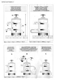
8.6 RESIN AND SOFTENER<br />
REGENERATION<br />
C<br />
3) Reposition lever D towards the left (Fig. 39).<br />
To avoid scaling deposits in the boiler and in<br />
the heating exchangers, the softener must<br />
always be kept efficient. Therefore, the ionic<br />
resins must be regularly regenerated.<br />
Regeneration times are established according<br />
to the quantity of coffee delivered daily and<br />
the hardness of the water utilised.<br />
As an indication, regeneration times can be<br />
calculated on the basis diagram illustrated in<br />
Fig. 35.<br />
C<br />
IN<br />
OUT<br />
E<br />
D<br />
Fig. 36<br />
G<br />
D<br />
Fig. 39<br />
ENGLISH<br />
D<br />
Fig. 37<br />
Fig. 35<br />
Regeneration procedures are as follows:<br />
1) Turn the machine off and place a container<br />
large enough to contain at least 5 litres<br />
under tube E (Fig. 36).<br />
Turn levers C and D from left to right; take<br />
the cap off by unscrewing knob and fill with<br />
1 Kg normal kitchen salt (Fig. 37).<br />
2) Put the cap back on and reposition lever C<br />
moving it towards the left (Fig. 38) and allowing<br />
tube F to discharge the salty water until<br />
it has been eliminated and the water becomes<br />
fresh again (about half and hour).<br />
C<br />
F<br />
Fig. 38<br />
59
9. AURELIA PLUS MACHINE FUNCTION MESSAGES<br />
DISPLAY AND KEY<br />
INDICATIONS<br />
CAUSE<br />
EFFECT<br />
SOLUTION<br />
NOTES<br />
ENGLISH<br />
DIAGNOSIS OF ERROR<br />
DELIVERY ERROR<br />
At the time of the diagnosis<br />
the system presents<br />
faults within the control<br />
unit EPROM.<br />
On reaching delivery<br />
time limit (120 seconds)<br />
the doser doesn’t send<br />
out its set commands.<br />
The machine will not<br />
heat and all its functions<br />
will be blocked.<br />
The display indicator and<br />
the ‘continuous’ key<br />
belonging to the relative<br />
unit will flash on and off.<br />
Press the<br />
RESET<br />
key or one of the keys<br />
DOSER ERROR<br />
If the doser doesn’t send<br />
out its set commands<br />
within the first three<br />
seconds from delivery<br />
onset.<br />
If the delivery isn’t<br />
manually halted, the<br />
maximum time limit (120<br />
sec) will be blocked.<br />
Press the<br />
RESET<br />
key or one of the keys<br />
LEVEL ERROR<br />
If after 90 sec of machine<br />
functioning the water<br />
level is not re-established.<br />
The display indicator will<br />
flash on and off. The<br />
pump is de-activated.<br />
The resistor and all the<br />
functions are halted.<br />
Turn the machine off<br />
and then turn it on<br />
again. All its functions<br />
will be re-activated.<br />
PRESSURE ERROR<br />
When the machine’s<br />
temperature is higher<br />
than 130°C.<br />
The display indicator<br />
will flash on and off and<br />
the resistor is de-activated.<br />
The system will be reestablished<br />
as soon as<br />
the temperature goes<br />
below 130°C.<br />
The boiler is provided<br />
with a manual refitting<br />
safety thermostat; if the<br />
resistor is not re-established,<br />
call a qualified<br />
technician.<br />
60
DISPLAY AND KEY<br />
INDICATIONS<br />
CAUSE<br />
EFFECT<br />
SOLUTION<br />
NOTES<br />
OVERCURRENT ERR.<br />
FINE GRINDING<br />
COARSE GRINDING<br />
Incorrect electrical input<br />
caused by a malfunction<br />
in one of the machine<br />
charges.<br />
The machine registers<br />
values different from the<br />
set values.<br />
The machine registers<br />
values different from the<br />
set values.<br />
The display reading will<br />
flash. The pump will<br />
switch off. The heating<br />
element and all other<br />
functions will be disabled.<br />
A much longer delivery<br />
time.<br />
A much shorter delivery<br />
time.<br />
Switch off the machine<br />
and send for a specialist<br />
technical engineer.<br />
Modify grinding degree<br />
and press the key<br />
RESET<br />
or one of the keys<br />
Press the<br />
RESET<br />
key or one of the keys<br />
By leaving the machine in<br />
the programming state,<br />
within 10 minutes from the<br />
last selection, the system will<br />
return to the previous configuration<br />
and the display will<br />
indicate its reestablishment<br />
of normal functioning.<br />
ENGLISH<br />
61
10. Aurelia V MACHINE FUNCTION MESSAGES<br />
DISPLAY AND KEY<br />
INDICATIONS<br />
CAUSE<br />
EFFECT<br />
SOLUTION<br />
NOTES<br />
ENGLISH<br />
If the doser doesn’t send<br />
out its commands within<br />
three sec from the onset<br />
of delivery.<br />
If the delivery is not halted<br />
manually, the time<br />
limit (120 sec.) will be<br />
blocked.<br />
Interrupt the delivery.<br />
+<br />
+ ECC<br />
If within 90 sec. from<br />
onset, with pump inserted<br />
during the levelling,<br />
at 180 sec., if the level<br />
has not been re-established.<br />
The pump, the resistor<br />
and all the functions will<br />
be halted.<br />
Turn the machine off for<br />
at least 5 sec. and then<br />
switch it on again.<br />
62
11. Aurelia S MACHINE FUNCTION MESSAGES<br />
DISPLAY AND KEY<br />
INDICATIONS<br />
CAUSE<br />
EFFECT<br />
SOLUTION<br />
NOTES<br />
+ + ECC<br />
If within 90 sec. from<br />
onset, with pump inserted<br />
during the levelling,<br />
at 180 sec., if the level<br />
has not been re-established.<br />
The pump, the resistor<br />
and all the functions will<br />
be halted.<br />
Turn the machine off for<br />
at least 5 sec. and then<br />
switch it on again.<br />
ENGLISH<br />
63
IMPIANTO ELETTRICO /ELECTRIC SYSTEM Aurelia S<br />
13<br />
12<br />
4<br />
8 7 11 10<br />
14<br />
9<br />
6<br />
5<br />
1<br />
3<br />
2<br />
Fig. 40<br />
LEGENDA/KEY<br />
1 MS Interruttore/ Main Switch.<br />
2 R Relè/Relay.<br />
3 P Pressostato/Pressostat.<br />
4 PM Motore pompa/Pump Motor.<br />
5 HE Resistenza boiler/ Heater ELEMENT.<br />
6<br />
7<br />
TE Termostato/Thermostat.<br />
EV2 Elettrovalvola gruppo 2/ Solenoid<br />
Valve unit 2.<br />
8 EV1 Elettrovalvola gruppo 1/Solenoid<br />
Valve unit 1.<br />
9 LP Sonda livello/ level Probe.<br />
10 EV4 Elettrovalvola gruppo 4/Solenoid<br />
Valve unit 4.<br />
11 EV 3 Elettrovalvola gruppo 3/Solenoid<br />
Valve unit 3.<br />
12 EVHW Elettrovalvola miscelatore/Solenoid<br />
Valve mixer.<br />
13 EVC Uscita scaldatazze/Cup-warmer out<br />
put.<br />
14 EVL Elettrovalvola livello/Solenoid Valve<br />
level.<br />
64
IMPIANTO ELETTRICO /ELECTRIC SYSTEM Aurelia Plus Rel 3.xx<br />
14<br />
13<br />
15<br />
9<br />
4<br />
12<br />
6<br />
8<br />
7<br />
11<br />
10<br />
1<br />
2<br />
5<br />
3<br />
Fig. 41<br />
LEGENDA/KEY<br />
1 MS Interruttore/ Main Switch.<br />
2 R Relè/Relay.<br />
3 P Pressostato/Pressostat.<br />
4 PM Motore pompa/Pump Motor.<br />
5 HE Resistenza boiler/ Heater ELEMENT.<br />
6 TE Termostato/Thermostat.<br />
7 EV2 Elettrovalvola gruppo 2/ Solenoid<br />
Valve unit 2.<br />
8 EV1 Elettrovalvola gruppo 1/Solenoid<br />
Valve unit 1.<br />
9 LP Sonda livello/ level Probe.<br />
10 EV4 Elettrovalvola gruppo 4/Solenoid<br />
Valve unit 4.<br />
11 EV 3 Elettrovalvola gruppo 3/Solenoid<br />
Valve unit 3.<br />
12 TP Sonda temperatura/Temperature Probe<br />
13 EVHW Elettrovalvola miscelatore/Solenoid<br />
Valve mixer.<br />
14 EVC Uscita scaldatazze/Cup-warmer out<br />
put.<br />
15 EVL Elettrovalvola livello/Solenoid Valve<br />
level.<br />
65
IMPIANTO ELETTRICO /ELECTRIC SYSTEM Aurelia Plus Rel 1.xx<br />
14<br />
13<br />
15<br />
9<br />
4<br />
12<br />
6<br />
10<br />
11<br />
7<br />
8<br />
1<br />
5<br />
2<br />
3<br />
Fig. 41<br />
LEGENDA/KEY<br />
1 MS Interruttore/ Main Switch.<br />
2 R Relè/Relay.<br />
3 P Pressostato/Pressostat.<br />
4 PM Motore pompa/Pump Motor.<br />
5 HE Resistenza boiler/ Heater ELEMENT.<br />
6 TE Termostato/Thermostat.<br />
7 EV2 Elettrovalvola gruppo 2/ Solenoid<br />
66<br />
Valve unit 2.<br />
8 EV1 Elettrovalvola gruppo 1/Solenoid<br />
Valve unit 1.<br />
9 LP Sonda livello/ level Probe.<br />
10 EV4 Elettrovalvola gruppo 4/Solenoid<br />
Valve unit 4.<br />
11 EV 3 Elettrovalvola gruppo 3/Solenoid<br />
Valve unit 3.<br />
12 TP Sonda temperatura/Temperature Probe<br />
13 EVHW Elettrovalvola miscelatore/Solenoid<br />
Valve mixer.<br />
14 EVC Uscita scaldatazze/Cup-warmer out<br />
put.<br />
15 EVL Elettrovalvola livello/Solenoid Valve<br />
level.
IMPIANTO ELETTRICO /ELECTRIC SYSTEM Aurelia V<br />
14<br />
13<br />
15<br />
8<br />
7 11 10<br />
9<br />
12<br />
4<br />
6<br />
5<br />
1<br />
2<br />
3<br />
Fig. 42<br />
LEGENDA/KEY<br />
1 MS Interruttore/ Main Switch.<br />
2 R Relè/Relay.<br />
3 P Pressostato/Pressostat.<br />
4 PM Motore pompa/Pump Motor.<br />
5 HE Resistenza boiler/ Heater ELEMENT.<br />
6 TE Termostato/Thermostat.<br />
7 EV2 Elettrovalvola gruppo 2/ Solenoid<br />
Valve unit 2.<br />
8 EV1 Elettrovalvola gruppo 1/Solenoid<br />
Valve unit 1.<br />
9 LP Sonda livello/ level Probe.<br />
10 EV4 Elettrovalvola gruppo 4/Solenoid<br />
Valve unit 4.<br />
11 EV 3 Elettrovalvola gruppo 3/Solenoid<br />
Valve unit 3.<br />
12 TP Sonda temperatura/Temperature Probe<br />
13 EVHW Elettrovalvola miscelatore/Solenoid<br />
Valve mixer.<br />
14 EVC Uscita scaldatazze/Cup-warmer out<br />
put.<br />
15 EVL Elettrovalvola livello/Solenoid Valve<br />
level.<br />
67
IMPIANTO IDRAULICO /PLUMBING SYSTEM<br />
10<br />
19<br />
18<br />
15<br />
14<br />
9<br />
13<br />
8<br />
11<br />
12<br />
16<br />
17<br />
6<br />
1 2 3 5 4<br />
Fig. 43<br />
LEGENDA/KEY<br />
1 Rubinetto ingresso acqua/Water entrance<br />
faucet<br />
2 Pompa/Pump<br />
3 Valvola di ritegno/Check valve<br />
4 Valvola neplas/Neplas valve<br />
5 Dosatore volumetrico/Volume doser<br />
6 Elettrovalvola di livello/Solenoid valve level<br />
68<br />
7 Rubinetto livello manuale/<strong>Manual</strong> level fau<br />
cet<br />
8 Livello acqua/Water level<br />
9 Gruppo erogatore/Delivery unit<br />
10 Pressostato/Pressostat<br />
11 Manometro doppia scala/Double scale<br />
gauge<br />
12 Scambiatore di calore/Heat exchanger<br />
13 Vapore/Steam<br />
14 Valvola di sicurezza cald./Heater safety<br />
valve<br />
15 Valvola antirisucchio/Anti-suction valve<br />
16 Economizzatore acqua calda/Hot water<br />
economiser<br />
17 Depuratore/Purifier<br />
18 Sonda livello/Level probe<br />
19 Scaldatazze a vapore (optional)/Steam<br />
cup-warmer (optional).