Download - Topcon
Download - Topcon
Download - Topcon

Create successful ePaper yourself
Turn your PDF publications into a flip-book with our unique Google optimized e-Paper software.
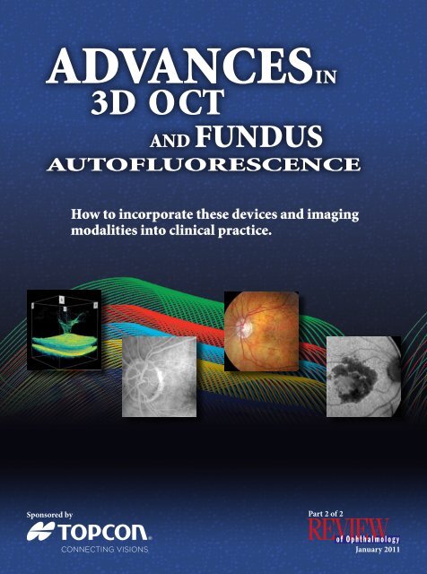
Advancesin<br />
3D oct<br />
and Fundus<br />
Autofluorescence<br />
How to incorporate these devices and imaging<br />
modalities into clinical practice.<br />
Sponsored by<br />
Part 2 of 2<br />
January 2011
Advances in 3D OCT and Fundus Autofluorescence<br />
How to incorporate these devices and imaging<br />
modalities into clinical practice.<br />
At the 2010 American Academy of Ophthalmology Joint<br />
Meeting with the Middle East Africa Council of Ophthalmology<br />
in Chicago, an expert panel of ophthalmologists gathered<br />
to discuss new OCT uses and fundus autofluorescence. The<br />
following pages offer a recap of their presentations.<br />
Fundus Autofluorescence in the<br />
Management of AMD<br />
The days of color stereoscopic imaging are numbered;<br />
the future is in autofluorescence and 3D OCT.<br />
by Philip J. Rosenfeld, MD, PhD<br />
I<br />
am a newcomer to autofluorescence,<br />
and I am slowly<br />
convincing my colleagues to<br />
incorporate it into their practices.<br />
It’s a great strategy for making<br />
diagnoses and following patients<br />
to assess disease progression.<br />
I mostly deal with age-related<br />
macular degeneration (AMD),<br />
so I will explain how I incorporate<br />
autofluorescence into<br />
my clinical practice to follow<br />
patients with AMD.<br />
Geographic Atrophy:<br />
Not to Be Ignored<br />
We often focus on choroidal neovascularization<br />
(CNV) in AMD, but<br />
geographic atrophy (GA) really determines<br />
how our patients function<br />
on a day-to-day basis. As we treat<br />
patients over the years, we are going<br />
to face a progression of GA and we<br />
The opinions expressed in this supplement to Review of Ophthalmology do not necessarily reflect the views,<br />
or imply endorsement, of the editor or publisher. Copyright 2011, Review of Ophthalmology. All rights reserved.<br />
2 Review of Ophthalmology January 2011
have to come up with a treatment for<br />
this disease.<br />
GA has been intensively investigated<br />
over the past couple of<br />
decades, and Janet Sunness and<br />
her colleagues have come up with<br />
certain patterns of growth: slow,<br />
medium and fast, based on color<br />
fundus photography. 1 This ends up<br />
being important because we first<br />
need to know how this entity grows<br />
before we can prove that treatments<br />
have been developed to slow or stop<br />
its progression.<br />
Historically, color fundus photography<br />
has been the gold standard.<br />
Then came autofluorescence, and<br />
when you compare it to color fundus<br />
photography (see Figure 1), you can<br />
really see a difference. This figure<br />
compares color fundus photography<br />
with a <strong>Topcon</strong> autofluorescence image<br />
from the same patient showing<br />
Figure 1. Comparison of color fundus photography to autofluorescence for imaging geographic atrophy.<br />
progression of GA over 2.5 years.<br />
Frank Holz took Sunness’s work and<br />
expanded it to include autofluorescence.<br />
2 He came up with some<br />
interesting findings in terms of the<br />
way lesions grow based on different<br />
patterns of autofluorescence.<br />
The key to following the progression<br />
of GA is to follow the edge of<br />
GA as it progresses toward the foveal<br />
center. Early in the disease process,<br />
most patients present with areas of<br />
patchy GA, but they still have 20/20<br />
vision. Over time, these areas grow<br />
The Dawn of a New Filter<br />
By Richard F. Spaide, MD<br />
Fundus autofluorescence (FAF) comes from a number<br />
of different sources. The precursor for all of it comes from the retina,<br />
particularly from the outer segments (principally retinoids and also potentially from oxidatively<br />
damaged molecules). So the precursors to autofluorescence develop in the retina, and these<br />
precursors accumulate as an ordinary part of life. However, in disease states, the precursors can<br />
also accumulate prior to phagocytosis of the outer segments by the retinal pigment epithelium<br />
(RPE). Once phagocytized by the RPE, many of the components of the other segments are<br />
recycled and transported to the photoreceptors for reuse. Indigestible material, particularly that<br />
derived from crosslinking between retinoids and themselves or other molecules, are concentrated<br />
and stored in liposomes to create lipofuscin. Most of the FAF we ordinarily record is derived from<br />
lipofuscin in the RPE. Various diseases can be associated with increased lipofuscin in the RPE,<br />
which causes increased autofluorescence. Some disease states, particularly those leading to accumulation<br />
of yellowish vitelliform material in the subretinal space, have increased autofluorescence<br />
arising from extracellular sources.<br />
(continued on page 4)<br />
Review of Ophthalmology January 2011 3
and coalesce and eventually, the patient<br />
will lose vision. As the GA gets<br />
closer to the foveal center, patients<br />
become increasingly aware of their<br />
decreasing visual field and acuity.<br />
Various imaging strategies have<br />
been tested in clinical trials for<br />
following GA. These include color<br />
fundus photography, autofluorescence,<br />
3D OCT and fluorescein<br />
angiography (see Figure 2). Fluorescein<br />
angiography is avoided in<br />
routine clinical care because it’s<br />
invasive and unnecessary unless<br />
CNV is suspected. Most of our<br />
clinical experience has been with<br />
color fundus photography or autofluorescence.<br />
Which of these is better<br />
and is autofluorescence imaging<br />
strategy superior?<br />
Comparing Technologies<br />
The choice between imaging<br />
strategies is currently under debate.<br />
Reading centers tend to prefer<br />
stereoscopic viewing of color fundus<br />
photography, but in today’s clinical<br />
practice, stereoscopic viewing is<br />
rapidly becoming a lost art. Trying to<br />
train fellows in stereoscopic viewing<br />
nowadays is almost impossible<br />
because of autofluorescence and optical<br />
coherence tomography (OCT).<br />
Autofluorescence and OCT really<br />
make stereoscopic viewing unnecessary,<br />
especially since the future of<br />
imaging and viewing of images will<br />
be all digitally based.<br />
A paper by the National Eye<br />
Institute at the most recent American<br />
Academy of Ophthalmology<br />
meeting in Chicago compared<br />
color fundus photography with<br />
autofluorescence and found that<br />
the two were similar in detecting<br />
The Dawn of a New Filter<br />
(continued from page 3)<br />
Detecting Autofluorescence<br />
There are different ways to detect autofluorescence. One is to use confocal imaging<br />
(that is the idea behind a scanning laser ophthalmoscope) and the advantage to this method is<br />
that only light originating from the retina and the RPE gets imaged by the instrument, but in<br />
many cases, it can reject autofluorescence from the lens.<br />
With Heidelberg’s Spectralis, the excitation wavelength is 488 nm, which is a blue-green color.<br />
According to the company, they have a band pass filter that starts at 500 nm. Essentially, that<br />
means they use the fluorescein filters for autofluorescence; they just turn up the gain of the instrument,<br />
which means you cannot do fluorescein imaging before autofluorescence imaging because<br />
of the residual fluorescein within the eye. Macular pigment is designed to block blue light and absorbs<br />
the excitation light produced by the Spectralis. I wanted to be able to image autofluorescence<br />
with a fundus camera because at the time, we didn’t have a Heidelberg instrument. The problem<br />
with using conventional wavelengths used by scanning laser ophthalmology devices is that they<br />
also cause the crystalline lens to autofluoresce. So the excitation wavelength was moved to a somewhat<br />
longer wavelength as was the peak of the barrier filter. This markedly reduced the autofluorescence<br />
from the lens and also removed the problem with macular pigment. There is evidence<br />
that blue light can cause apoptosis in RPE cells containing lipofuscin, so there is an additional<br />
theoretical advantage to using longer wavelengths. Through improved science and state-of-the-art<br />
manufacturing processes, the excitation and barrier filters are approximately 20 times more efficient<br />
than older generation fundus autofluorescence filters. The image quality produced is good,<br />
but requires user intervention to adjust the image in terms of contrast. This contrast adjustment is<br />
done automatically in the Heidelberg Spectralis.<br />
4 Review of Ophthalmology January 2011
GA, but that area measurements,<br />
growth rates and estimates of foveal<br />
involvement did differ. 3 These findings<br />
are important because patients<br />
lose vision with foveal involvement,<br />
and foveal involvement is what we<br />
are trying to avoid. So knowing<br />
when the fovea is threatened or<br />
involved is vital information for the<br />
clinician and the patient.<br />
Figure 2. Strategies tested in clinical trials for following geographic atrophy.<br />
Figure 3. Imaging of GA using different devices.<br />
Tracking Foveal Involvement<br />
So the major questions are, can<br />
we measure GA? Can we follow GA,<br />
and do we know when it is encroaching<br />
on the foveal center?<br />
I am running a clinical trial to<br />
determine whether we can stop<br />
the growth of GA using a complement<br />
inhibitor. All patients enrolled<br />
in the clinical trial have vision of<br />
20/63 or better (high-risk drusen<br />
cohort, n=30; GA cohort, n=30).<br />
They receive either the complement<br />
inhibitor known as eculizumab or<br />
placebo over 26 weeks and then they<br />
are followed for at least one year.<br />
This Phase II study compares<br />
different imaging modalities<br />
(color fundus photography, Heidelberg<br />
Engineering’s Spectralis<br />
HRA and <strong>Topcon</strong> Medical Systems’<br />
TRC-50DX) to determine<br />
the best imaging strategy for GA.<br />
The goal is to compare these imaging<br />
approaches when establishing<br />
boundaries of GA, following<br />
boundaries over time, calculating<br />
growth rates, determining drug<br />
efficacy and identifying foveal<br />
center involvement.<br />
Figure 3 compares three different<br />
imaging strategies and<br />
demonstrates how the <strong>Topcon</strong><br />
Spaide filters for detecting autofluorescence<br />
are superior to color<br />
fundus photography and the<br />
Heidelberg autofluorescence images.<br />
Only the <strong>Topcon</strong> filters can<br />
reproducibly and reliably identify<br />
foveal center involvement in<br />
cases of GA in which the fovea<br />
is not involved; these are just the<br />
kind of patients that we follow in<br />
clinic and enroll in clinical trials.<br />
Due to the excitation wavelength<br />
used by the Heidelberg system,<br />
the retinal pigment epithelium<br />
(RPE) in the central macula<br />
does not autofluoresce because<br />
the overlying luteal pigment in<br />
the retina absorbs the light and<br />
prevents the light from ever<br />
reaching the RPE. The excitation<br />
wavelength delivered by the<br />
<strong>Topcon</strong> Spaide filters is outside<br />
the absorption range of the luteal<br />
pigments, so a clear, crisp, reliable<br />
view of the central macula is<br />
achieved.<br />
More than 90 percent of the<br />
patients enrolled have a complication<br />
when trying to detect<br />
foveal involvement with the Heidelberg<br />
autofluorescence system.<br />
In these cases, I cannot rely on<br />
autofluorescence alone; I have to<br />
use another modality to detect<br />
foveal involvement. With the<br />
<strong>Topcon</strong> filters, I can see what is<br />
going on in the foveal center and<br />
I can map the boundaries. GA is<br />
just easier to identify and follow<br />
with the <strong>Topcon</strong> autofluorescence<br />
instrument.<br />
While most of the published studies<br />
using autofluorescence to image<br />
GA have used the Heidelberg confocal<br />
scanning laser ophthalmoscope,<br />
in real world clinical practice, the<br />
<strong>Topcon</strong> approach is superior.<br />
Review of Ophthalmology January 2011 5
Real-Life Applications<br />
The <strong>Topcon</strong> autofluorescence<br />
digital system is ideal for identifying<br />
GA and following patients<br />
with GA. For clinical trials designed<br />
to explore emerging treatments<br />
for GA, the <strong>Topcon</strong> system<br />
should be a necessity. Over the<br />
next few years, as we continue to<br />
learn more about dry AMD and<br />
study these emerging therapies,<br />
the usefulness of the <strong>Topcon</strong><br />
filters will become increasingly<br />
obvious.<br />
Philip J. Rosenfeld, MD, PhD,<br />
is professor of Ophthalmology<br />
at the Bascom Palmer Eye<br />
Institute of the University of<br />
Miami Miller School of Medicine<br />
and is a retinal specialist.<br />
He also serves as Medical<br />
Editor of Review of Ophthalmology’s Retina<br />
Online e-newsletter.<br />
REFERENCES<br />
1. Sunness JS, Margalit E, Srikumaran D, et al.<br />
The long-term natural history of geographic<br />
atrophy from age-related macular degeneration:<br />
enlargement of atrophy and implications<br />
for interventional clinical trials. Ophthalmology<br />
2007;114(2):271-277.<br />
2. Holz FG, Bindewald-Wittich A, Fleckenstein<br />
M, et al. Progression of geographic atrophy and<br />
impact of fundus autofluorescence patterns in agerelated<br />
macular degeneration. Am J Ophthalmol<br />
2007;143(3):463-472.<br />
3. Domalpally A, et al. Geographic atrophy from<br />
color and autofluorescence images. Paper presented<br />
at: AAO Joint Meeting, 2010 Oct 16-19; Chicago.<br />
Comparison of SD-OCT Devices<br />
and 3D OCT Drusen Analysis<br />
Software<br />
A look at the history of OCT devices, what they can<br />
do and how to use them in clinical practice.<br />
by Peter K. Kaiser, MD<br />
In the 1990s, Zeiss licensed<br />
time-domain optical coherence<br />
tomography (OCT) technology<br />
from James Fujimoto’s lab at<br />
Massachusetts Institute of Technology<br />
(MIT) and made a commercial<br />
scanner, but the popularity of the<br />
technology for most of us in clinical<br />
practice didn’t really begin until<br />
the software was improved and the<br />
Stratus OCT (Carl Zeiss Meditec)<br />
came along in 2002. The Stratus<br />
was an improvement in both speed<br />
and axial resolution over the earlier<br />
models, but more importantly, the<br />
software algorithms allowed us to<br />
follow patients over time. The big<br />
explosion in OCT technology came<br />
in 2007 with the first spectral domain<br />
OCT (SD-OCT) devices coming<br />
to market. By evaluating all the<br />
images and light and wavelength<br />
parameters simultaneously (in contrast<br />
to the serial approach used in<br />
the older time-domain OCT), there<br />
was a huge jump in the speed of image<br />
acquisition. Since this technology<br />
was in the public domain, many<br />
companies could produce spectral<br />
domain devices. Let’s look at how<br />
these devices differ.<br />
Today’s SD-OCT Devices<br />
The SD-OCT devices used today<br />
all pretty much utilize the same<br />
wavelength (see Figure 1), although<br />
with the advent of enhanced depth<br />
imaging (EDI), which I will get into<br />
later, we are finding that scanning<br />
depth actually matters. In fact,<br />
devices with deeper scanning depths<br />
are more attractive for EDI because<br />
we are now actually able to image the<br />
choroid. Axial resolution depends on<br />
the wavelength of light you are using<br />
and because the wavelengths are all<br />
pretty similar, the axial resolutions<br />
are also going to be similar. One factor<br />
that differs between these devices<br />
is scanning speed.<br />
With OCT, faster isn’t always<br />
better because the faster you go, the<br />
more noise is introduced into the<br />
images and the more you have to use<br />
image averaging to get a good image.<br />
The final thing that differs between<br />
these devices is the ancillary imaging<br />
they include. Aside from OCT,<br />
some devices include other imaging<br />
capabilities such as color fundus<br />
photography, fundus autofluorescence,<br />
fluorescein angiography,<br />
indocyanine green angiography and<br />
6 Review of Ophthalmology January 2011
scanning laser ophthalmoscopy.<br />
The shared features of all these<br />
devices are that they have improved<br />
resolution, more accurate retinal<br />
maps, improved registration/orientation<br />
(because we have so much<br />
information), cube scans and 3D<br />
views, which were not possible with<br />
previous devices (see Figure 2).<br />
Image averaging. As I mentioned,<br />
high-speed imaging requires image<br />
averaging (a photographic technique)<br />
to produce a good image.<br />
This technique overlaps multiple<br />
images from the same location, and<br />
any noise in the image will appear<br />
as a difference between the images.<br />
So if you overlap multiple images,<br />
anything that changes is considered<br />
noise and is subtracted out to produce<br />
the high-resolution OCT images<br />
that we see. Therefore, by using<br />
image averaging technology, one can<br />
produce higher resolution, higher<br />
contrast images with less speckle and<br />
noise. Although most companies’<br />
devices now perform image averaging,<br />
some really don’t need to. Also,<br />
note that image averaging takes<br />
time, which may make it difficult to<br />
perform image averaging and image<br />
a large cube of the retina.<br />
Views from a Different<br />
Dimension<br />
In the past, we could not image the<br />
choroid very well with OCT. OCT<br />
provided excellent cross-sectional<br />
images of the retina and retinal pigment<br />
epithelium (RPE), but imaging<br />
of the choroid was poor. A new<br />
technique was recently developed by<br />
Dr. Spaide to provide better imaging<br />
of choroid and sub-RPE space:<br />
EDI. 1 We are finding that choroidal<br />
Device Wavelength Scanning Axial Scanning Ancillary<br />
Depth Resolution Speed Imaging<br />
Bioptigen 840 nm 2.3 mm 3–5 µm 17,000<br />
3D SDOCT 1<br />
Carl Zeiss 840 nm 2 mm 5 µm 27,000<br />
Meditec Cirrus 1<br />
Heidelberg 870 nm 1.9 mm 7 µm 40,000 SLO/FA/ICG/<br />
Spectralis OCT 1<br />
Autofluorescence<br />
Opko/OTI 840 nm 2.3 mm 5–6 µm 27,000 SLO/ICG/<br />
Spectral OCT/SLO 1<br />
microperimetry<br />
Optovue 840 nm 2.3 mm 5 µm 26,000<br />
RTVue-100 1<br />
Canon/Optopol 840 nm 2 mm 6 µm 25,000<br />
SPOCT 1<br />
Canon/Optopol 850 nm 2 mm 3 µm 52,000<br />
SPOCT • HR 2<br />
<strong>Topcon</strong> 840 nm 2.3 mm 5–6 µm 27,000 color fundus<br />
3D OCT-2000 1<br />
(12.3 MP)<br />
<strong>Topcon</strong> 3D 840 nm 2.3 mm 5–6 µm 50,000 color fundus, FA,<br />
OCT-2000 FA (+) 2 RF, FAF (+)<br />
1 510(k) approved<br />
2<br />
510(k) pending<br />
Figure 1. SD-OCT hardware comparison.<br />
thickness correlates with age and<br />
refractive status, and is thickened<br />
in certain diseases such as central<br />
serous choroidopathy.<br />
Because spectral domain has<br />
such huge datasets, we can not only<br />
look at the images in 3D, but we can<br />
also look at the data from another<br />
dimension, which we were not<br />
able to do with time domain OCT:<br />
Z-plane or C-scanning. Conventional<br />
B-Scanning results from fixed<br />
Z-axis, while C-scanning allows for<br />
the scans to be performed along the<br />
Figure 2. 3D view with <strong>Topcon</strong> device.<br />
Z-axis creating true en-face images.<br />
In other words, we are looking at it<br />
from the top down; whereas we are<br />
used to looking at it in cross section.<br />
So, for instance, if you look at<br />
a macular hole from the side, it is<br />
pretty obvious, but if you look at it<br />
from the top down in the C-scan<br />
mode, you can dive into these macular<br />
holes. I like to show these to my<br />
patients because you can conceptualize<br />
for them why their epiretinal<br />
membrane, for example, is causing a<br />
distortion in their vision.<br />
All of the OCT devices are starting<br />
to perform C-scan imaging and we<br />
are finding new uses for it in terms<br />
of macular degeneration in particular<br />
(see Figure 3).<br />
Hardware-Specific Features<br />
Some of these OCT devices also<br />
have an anterior segment imaging<br />
mode that allows you to look at<br />
anterior segment structures such<br />
as whether the lens is in the bag,<br />
Review of Ophthalmology January 2011 7
Purchase Pointers<br />
By Peter K. Kaiser, MD<br />
If you are looking to update your practice in this area,<br />
my best advice is for you to sit down and try the devices; see how easy<br />
is it for you to use the software, how quickly can you actually scan a patient and look at the<br />
image quality. Do you like it? If you have a practice with glaucoma specialists, for instance,<br />
you will want to make sure there’s an optic nerve normative database.<br />
A feature that people don’t often consider is legacy support, which not all companies offer.<br />
You may have Stratus OCT (Carl Zeiss Meditec) information from your old scanner, and if<br />
you are upgrading to one of the new spectral domain devices, you still want to be able to look<br />
at that Stratus data. The Cirrus HD-OCT (Carl Zeiss Meditec) comes with reader software,<br />
but requires two different programs to run at the same time. With other OCT devices, you<br />
can also purchase this Stratus reading software. <strong>Topcon</strong> has actually made a more elegant solution:<br />
it built reading software for the Stratus into its new SD-OCT devices. Finally, you will<br />
want to consider the company’s track record with regard to future support. Will the company<br />
be around in four or five years so your device will be continuously upgraded?<br />
identify any problems with the<br />
cornea itself, measure the angle,<br />
etc. Another thing to consider<br />
when you look at these devices is<br />
whether there is a way to make a<br />
reference image that you can use to<br />
pinpoint changes between visits. The<br />
3D OCT-2000 (<strong>Topcon</strong>) uses the<br />
fundus photograph, whereas Cirrus<br />
(Carl Zeiss Meditec) uses false fundus<br />
representation and Heidelberg’s<br />
Spectralis OCT uses eye-tracking<br />
software. This device has other<br />
imaging modes: BluePeak Autofluorescence<br />
Imaging, fluorescein<br />
angiography, SD-OCT, indocyanine<br />
green angiography, infrared imaging,<br />
red-free imaging and is able to<br />
pinpoint between any of those imaging<br />
modalities. The 3D OCT-2000<br />
Spectral Domain OCT also offers<br />
fundus autofluorescence, fluorescein<br />
Figure 3. C-scan with the <strong>Topcon</strong> device (left). Diving down in a C-scan mode from the retina into<br />
the choroid (right).<br />
angiography, color fundus photography<br />
and PinPoint Registration of<br />
OCT data as well as the other imaging<br />
modalities. So you need to know<br />
how the companies are comparing<br />
between visits to best decide if<br />
you’re doing a change analysis.<br />
The Spectral OCT/SLO device<br />
(Opko Health, Inc.) has a microperimetry<br />
unit built in, which allows<br />
you to do both microperimetry and<br />
change analysis.<br />
Bioptigen has a device that many<br />
people may not have heard of (3D<br />
SD-OCT), but is starting to gain<br />
more favor clinically. The company<br />
has been developing this intraoperative<br />
scanning head at Duke and we<br />
are finding that it may be beneficial<br />
in surgery.<br />
Susan Bender is working on a device<br />
with Zeiss that offers intraoperative<br />
OCT at the time of the surgery<br />
8 Review of Ophthalmology January 2011
Figure 4. Drusen mapping.<br />
live and in real time.<br />
Finally, the RTVue-100 (Optovue)<br />
offers wide-angle scans that can<br />
provide massive views of the retina,<br />
especially in a case, for instance,<br />
differentiating retinoschisis from<br />
retinal detachment.<br />
Mapping Drusen and<br />
Atrophy in Dry AMD<br />
Evaluating drusen size and<br />
volume, as well as geographic<br />
atrophy area, is something that is<br />
being added very shortly to a few<br />
OCT devices. We were fortunate<br />
to test both the Cirrus and <strong>Topcon</strong><br />
versions of this software, and they<br />
allow you to actually map changes<br />
in these parameters over time.<br />
Since the software cannot actually<br />
“see” drusen, it assumes that any<br />
elevations in the RPE over a certain<br />
threshold are drusen and use this to<br />
identify anything elevated as drusen<br />
(see Figure 4).<br />
From a scientific standpoint, you<br />
can see how error could be introduced<br />
into this type of measurement.<br />
So the key aspect of this software is<br />
how you can adjust for these elevations<br />
(by adjusting this threshold)<br />
and basically only evaluate the images<br />
that are correct and throw out<br />
the images that are incorrect. We are<br />
working closely with the companies<br />
to work out these issues. As treatments<br />
for dry AMD become a<br />
reality in the future, this type of<br />
analysis will become important.<br />
Comparing the Facts<br />
Now that we have reviewed the<br />
available and upcoming OCT devices,<br />
you can see that the OCT<br />
hardware is all pretty similar,<br />
though not all have eye tracking<br />
or ancillary imaging capabilities.<br />
When choosing an OCT device<br />
for your practice, keep in mind<br />
that it should be easy to use<br />
and patient-friendly to ensure<br />
efficient clinical operation. Additionally,<br />
the instrument should<br />
be competitively priced for all of<br />
its features, so you need to ask<br />
yourself what imaging capability<br />
you want and whether you use<br />
that in your clinical practice. The<br />
bottom line is that it’s all about<br />
the software. See the sidebar<br />
“Purchase Pointers” for more<br />
detailed information.<br />
Peter K. Kaiser, MD, is a Professor<br />
of Ophthalmology at the<br />
Cleveland Clinic Lerner College<br />
of Medicine and a staff member<br />
of the vitreoretinal department<br />
of the Cole Eye Institute.<br />
He is the Founding Director<br />
of the Digital Optical Coherence Tomography<br />
(OCT) Reading Center at the Cole Eye Institute<br />
(DOCTR) and on the editorial board of the<br />
American Journal of Ophthalmology, Retina,<br />
Retina Today, Retinal Physician and Ocular<br />
Surgery News.<br />
REFERENCES<br />
1. Spaide RF, Koizumi H, Pozonni MC. Enhanced depth<br />
imaging spectral-domain optical coherence tomography.<br />
Am J Ophthalmol 2008;146(4):496-500.<br />
Imaging and Swept Source OCT<br />
Getting a better look at the choroid.<br />
by Richard F. Spaide, MD<br />
Although the choroid is an<br />
important part of the eye<br />
and many ocular diseases<br />
originate from it, we don’t always<br />
think of it. We can use fluorescein<br />
to look at the eye, but it does not<br />
image the choroid particularly<br />
well. We have used indocyanine<br />
green angiography to obtain an<br />
image like a spider web of blood<br />
vessels and sometimes it is hard to<br />
figure out what is going on in the<br />
thickness of the choroid. We have<br />
also used ultrasound to look at the<br />
Review of Ophthalmology January 2011 9
choroid, but this method has poor<br />
axial resolution, so we developed<br />
a way to look at the choroid using<br />
spectral domain optical coherence<br />
tomography (SD-OCT).<br />
An Expanded Look at SD-OCT<br />
Ordinarily, SD-OCT does not<br />
produce particularly good images<br />
of the choroid because it has a<br />
depth-related roll off in sensitivity<br />
and because the melanin in<br />
the retinal pigment epithelium<br />
(RPE) and choroid is an enemy of<br />
coherence signals. What is most<br />
important for this discussion is the<br />
roll off in sensitivity with depth.<br />
Figure 1 shows you the red curve<br />
that illustrates the kind of signal<br />
that you get from SD-OCT. There<br />
are two parts of this curve and they<br />
are mirror images of each other,<br />
so one is a conjugate image that<br />
is upside-down compared to the<br />
other image.<br />
Ordinarily, instrument manufacturers<br />
put the peak sensitivity in the<br />
vitreous because they are looking<br />
at the vitreomacular interface for<br />
traction and so forth. But a typical<br />
SD-OCT gets dark because of<br />
a decrease in sensitivity to light, or,<br />
more accurately, to the coherence<br />
signal with depth. The idea behind<br />
enhanced depth imaging (EDI) is<br />
that you just push that peak sensitivity<br />
in closer to position around the<br />
scleral border. We lose the sensitivity<br />
to see the vitreous adequately<br />
by doing this. So you get one or the<br />
other. On the other hand, you see the<br />
scleral border quite easily. So with<br />
this method of SD-OCT imaging,<br />
we pick the choroid instead of the<br />
vitreous because you can’t get both<br />
at once. This feature is built into<br />
Heidelberg and <strong>Topcon</strong> software<br />
(Enhanced Choroidal Mode).<br />
The choroid is basically the<br />
thickest at the fovea in normal eyes.<br />
It thins a little bit temporally and<br />
more so toward the optic nerve. The<br />
choroid gets thinner with age, so<br />
when you are young, the subfoveal<br />
choroidal thickness is about 350 µm<br />
and ends up about 250 µm when you<br />
are older.<br />
The Choroid Up Close<br />
If there is enough permeability<br />
in the choroid to cause the RPE<br />
to be pushed up and to make a<br />
break in the RPE, then the choroid<br />
CASE REPORT<br />
By Richard F. Spaide, MD<br />
This patient was referred as an emergency because she had<br />
decreased acuity and her referring doctor was concerned that she had exudative macular<br />
degeneration. A look at the center of her macula showed that there were almost no visible blood vessels<br />
in the choroid. (There is one remaining blood vessel and some optic nerve pallor as well as beta zone<br />
atrophy.) Fluorescein showed that she did not have any choroidal neovascularization, but the choroid<br />
was so paper thin; it was almost gone. The diagnosis was age-related choroidal atrophy.<br />
Color fundus photo (left) and fluorescein image (right) of the patient<br />
in this case.<br />
Optical coherence tomography showing the patient’s age-related<br />
choroidal atrophy.<br />
10 Review of Ophthalmology January 2011
200 µm<br />
Figure 1. Ordinary (left); Inverted image, flipped (right).<br />
is probably going to be thick too.<br />
And a thick choroid helps confirm<br />
the diagnosis of central serous<br />
chorioretinopathy.<br />
In myopia, we have normal<br />
growth of the eye until the age<br />
of eight until about 12, then the<br />
eye expands. What happens to<br />
the choroid? In a -20D myope,<br />
for example, it seems that the<br />
same amount of choroid gets<br />
stretched down into a very thin<br />
layer. You also will not find<br />
many blood vessels inside the<br />
choroid of a myopic patient.<br />
The choroid gets so thin around<br />
the optic nerve that it can no<br />
longer support the life of the<br />
RPE. At this point, the choroid<br />
dies off and the sclera becomes<br />
visible. Older myopes usually<br />
have a much larger area of choroidal<br />
involvement than just the<br />
region of peripapillary atrophy.<br />
Getting a Handle on<br />
Swept Source OCT<br />
Light source OCT is a new kind<br />
of imaging technique available with<br />
time domain and SD-OCT that uses<br />
a broadband light source with many<br />
wavelengths of light simultaneously<br />
coming out at one time. It is actually<br />
an easier light source to make, but<br />
we have a fairly complicated way to<br />
interpret the signal once it comes<br />
back out of the eye.<br />
On the other hand, swept source<br />
OCT is a more complicated light<br />
source where, at each point, the<br />
wavelength of the light is quickly<br />
swept across a band of wavelengths.<br />
The resultant signal that gets detected<br />
by the machine is done with<br />
a system based on photodiodes,<br />
which is much more responsive and<br />
quicker than the charge-coupled<br />
devices (CCDs) used for SD-OCT.<br />
Swept source OCT commonly uses<br />
a longer wavelength light source<br />
because of availability.<br />
The fall-off in sensitivity for SD-<br />
OCT with increasing depth is not<br />
present to the same extent in swept<br />
source OCT. So far, at least in our<br />
<strong>Topcon</strong> prototype swept source<br />
OCT, we have not been able to<br />
make the peak sensitivity as good as<br />
that with SD-OCT, but because the<br />
response curve for swept source does<br />
not fall off much, you get a good<br />
image of both the retina and the choroid<br />
at the same time. The sensitivity<br />
is not yet there to image the vitreous<br />
all that well. One attribute of many<br />
swept source OCTs is that the scan<br />
rates are extremely fast. Our swept<br />
source prototype scans at 101,000<br />
A-scans per second.<br />
Wavelength, on the other hand,<br />
is a bit of a double-edge sword. If<br />
you use short wavelengths, you get<br />
high resolution, however, shorter<br />
wavelengths do not penetrate<br />
well. Longer (1µm) wavelengths<br />
penetrate better because they are<br />
not absorbed as well or reflected as<br />
much. But remember, the reflection<br />
of light is what gives us the<br />
signal, so even though it penetrates<br />
better, we are actually getting less<br />
signal back.<br />
So with swept source OCT, as it is<br />
currently being implemented, there<br />
may be somewhat decreased resolution<br />
and signal-to-noise ratio, but<br />
you get some things back: namely<br />
an improved ability to image greater<br />
depths as well as speed.<br />
Conclusion<br />
Choroidal imaging method is<br />
somewhat of a new frontier in<br />
imaging. I believe that we will be<br />
able to analyze the thickness and<br />
density of blood vessels in the<br />
choroid in the fairly near future<br />
and get an idea about what is<br />
going on in the choroid from a<br />
structural standpoint. There are<br />
some ways that we can do it now<br />
with SD-OCT, but it takes time<br />
because you have to average images<br />
together, but soon we will<br />
have swept source OCT and the<br />
image quality is going to improve<br />
over time.<br />
Richard F. Spaide, MD,<br />
practices at Vitreous, Retina,<br />
Macula Consultants of New<br />
York, where he specializes<br />
in diseases of the retina and<br />
vitreous. He has published more<br />
than 200 peer-reviewed articles<br />
as well as four books about the diagnosis and<br />
treatment of retinal diseases. Dr. Spaide is also<br />
an Associate Editor of the journal Retina and is<br />
on the editorial board of the American Journal<br />
of Ophthalmology.<br />
Review of Ophthalmology January 2011 11