2011 INTERNATIONAL OPTIMIST CLASS RULES
2011 INTERNATIONAL OPTIMIST CLASS RULES
2011 INTERNATIONAL OPTIMIST CLASS RULES

Create successful ePaper yourself
Turn your PDF publications into a flip-book with our unique Google optimized e-Paper software.
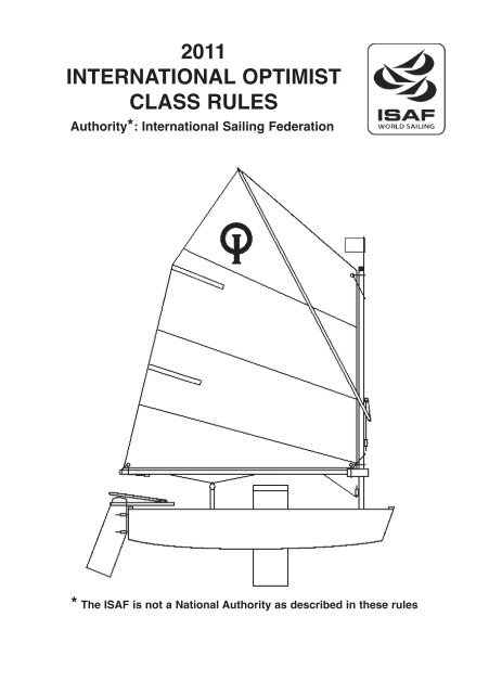
<strong>2011</strong><br />
<strong>INTERNATIONAL</strong> <strong>OPTIMIST</strong><br />
<strong>CLASS</strong> <strong>RULES</strong><br />
Authority*: International Sailing Federation<br />
* The ISAF is not a National Authority as described in these rules
CONTENTS<br />
Page<br />
Rule<br />
2 1 GENERAL<br />
2<br />
2<br />
2.<br />
2.1<br />
ADMINISTRATION<br />
English language<br />
2 2.2 Builders<br />
3 2.3 International Class Fee<br />
3 2.4 Registration and measurement certificate<br />
4 2.5 Measurement<br />
4 2.6 Measurement instructions<br />
5 2.7 Identification marks<br />
6 2.8 Advertising<br />
6 3 CONSTRUCTION AND MEASUREMENT <strong>RULES</strong><br />
6 3.1 General<br />
6 3.2 Hull<br />
6 3.2.1 Materials - GRP<br />
7 3.2.2 Hull measurement rules<br />
10 3.2.3 Hull construction details - GRP<br />
3.2.4 Hull construction details - Wood and Wood/Epoxy (See Appendix A, p 25)<br />
3.2.5 Not used<br />
12 3.2.6 Fittings<br />
13 3.2.7 Buoyancy<br />
14 3.2.8 Weight<br />
14 3.3 Daggerboard<br />
16 3.4 Rudder and Tiller<br />
19 3.5 Spars<br />
19 3.5.2 Mast<br />
20 3.5.3 Boom<br />
21 3.5.4 Sprit<br />
21 3.5.5 Running rigging<br />
22 4 ADDITIONAL <strong>RULES</strong><br />
5 (spare rule number)<br />
23 6 SAIL<br />
23 6.1 General<br />
23 6.2 Mainsail<br />
6.3 Spare rule number<br />
6.4 Spare rule number<br />
25 6.5 Class Insignia, National Letters, Sail Numbers and Luff Measurement Band<br />
26 6.6 Additional sail rules<br />
27 APPENDIX A: Rules specific to Wood and Wood/Epoxy hulls.<br />
29 PLANS. Index of current official plans.<br />
1
1 GENERAL<br />
1.1 The object of the class is to provide racing for young people at low cost.<br />
1.2 The Optimist is a One-Design Class Dinghy. Except where these rules specifically permit<br />
variations, boats of this class shall be alike in hull form, construction, weight and<br />
weight distribution, rigging spars and sail plan.<br />
Note: In deciding whether an item is permitted it should be noted that, in a One-Design<br />
Class, unless the rules specifically state that something is permitted it shall be<br />
assumed to be prohibited.<br />
1.3 These rules are complementary to the plans, measurement forms and measurement<br />
diagrams. Any request for interpretation and resolution thereof shall be made in accordance<br />
with current ISAF regulations.<br />
1.4 In the event of discrepancy between these rules, the measurement form and/or the plans<br />
the matter shall be referred to the ISAF.<br />
2 ADMINISTRATION<br />
2.1 English Language<br />
2.1.1 The official language of the class is English, and in the event of a dispute over interpretation<br />
the English text shall prevail.<br />
2.1.2 The word “shall” is mandatory and the word “may” is permissive.<br />
2.1.3 Wherever in these rules the words “Class Rules” are used they shall be taken as including<br />
the plans, diagrams and the measurement forms.<br />
2.1.4 The “National Class Association” is the International Optimist Class Association in the<br />
country concerned.<br />
2.2 Builders<br />
2.2.1 The Optimist may be built by any professional or amateur builder.<br />
2.2.2 Professional builders shall be responsible for supplying boats complying with the Rlass<br />
rules. The builder shall at his own expense correct or replace any boat which fails to<br />
pass measurement, due to an omission or error by the builder, provided that the boat is<br />
submitted for measurement within twelve months of purchase.<br />
2.2.3 Manufacturers of kits or parts shall be responsible for supplying parts, which, when<br />
assembled in accordance with the manufacturerʼs instructions (if any), will produce<br />
boats complying with the Class Rules. The manufacturer of the kit or parts which is<br />
shown not to do this shall, at his own expense, replace the parts of the kit which are<br />
incorrect provided that the error is made known to the manufacturer not more than<br />
twelve months from the date of purchase.<br />
2.2.4 A builder shall issue with each hull a written builderʼs declaration, stating that the hull<br />
complies with the relevant Class Rules.<br />
2
2.3 ISAF Class Fee<br />
2.3.1 The amount of the ISAF Class Fee is determined by the ISAF in consultation with IODA.<br />
The Executive Committee may alter this amount following such consultation.<br />
2.3.2 The ISAF Class Fee shall be paid by the builder on each hull as soon as building or<br />
moulding commences. For wood and wood/epoxy hulls the plaque shall be supplied at<br />
the time of measurement.<br />
2.3.3 The builder shall buy the building plaque and Registration Book:<br />
(a) for GRP hulls, from IODA<br />
(b) for wood and wood/epoxy hulls, from IODA or the National Optimist Association<br />
2.3.4 (a) IODA is responsible for collecting the ISAF Class Fee on behalf of the ISAF.<br />
(b) IODA will buy building plaques from ISAF unless otherwise agreed with the ISAF.<br />
(c) IODA or the National Association shall sell the plaques to the builder.<br />
Each plaque shall, at every stage, be sold with the official ISAF Class Fee receipt and the<br />
builders declaration form. The ISAF Class Fee receipt shall be sent to the appropriate<br />
National Authority when the boatʼs sail number is applied for.<br />
2.3.5 For each ISAF Class Fee paid IODA or the National Optimist Association shall issue a<br />
builderʼs declaration, ISAF International Class Fee receipt and an ISAF plaque, which the<br />
builder shall deliver with the hull to the owner. Builderʼs declarations and International<br />
Class Fee receipts are only valid if they are made out on the official forms issued by IODA.<br />
The building fee receipt and builderʼs declaration is incorporated in the Registration Book.<br />
2.4 Registration and Measurement Certificate<br />
2.4.1 No boat is permitted to race in the class unless it has a valid measurement certificate.<br />
This rule may be suspended in the case of charter boats at any event with the permission<br />
of the IODA Executive Committee.<br />
2.4.2 Each National Authority shall issue sail numbers which shall be consecutive and the<br />
number shall be preceded by the national letters. Numbering may restart at 1 on reaching<br />
number 9999. A National Authority shall issue a sail number only on receipt of evidence<br />
that the building fee has been paid.<br />
2.4.3 The certificate is obtained as follows:<br />
(a) The builder shall have the hull measured by a measurer officially recognised by his<br />
National Authority. The Registration Book with the ISAF International class fee<br />
receipt, builderʼs declaration and hull measurement form section completed shall be<br />
supplied to the owner of the boat.<br />
(b) The owner shall apply to the appropriate National Authority for a sail number enclosing<br />
their Registration Book with builderʼs declaration and building fee receipt. The<br />
National Authority shall enter the sail number in the Registration Book.<br />
(c) The owner is responsible for sending the Registration Book with the builderʼs declaration<br />
and all measurement form sections completed to his National Authority, together<br />
with any registration fee that may be required. On receipt of this the National<br />
Authority shall complete the measurement certificate section of the Registration Book<br />
and return it to the owner. Note that where a National Authority prefers to issue its<br />
own certificate this shall be firmly fixed to, and mentioned in the Registration Book.<br />
2.4.4 Change of ownership invalidates the measurement certificate but shall not necessitate<br />
remeasurement. The new owner shall apply to his National Authority for endorsement of the<br />
certificate/Registration Book returning it with any re-registration fee required and stating<br />
the necessary particulars.The measurement certificate/Registration Book shall then be<br />
3
eturned to the owner.<br />
2.4.5 If a replacement Registration book is required, it may be obtained from IODA. The new<br />
Registration book shall be printed with the same plaque number as the old Registration<br />
book. In the case of hulls produced before Registration Books were introduced, where<br />
the Measurement Certificate has been lost a National Authority may, after consultation<br />
with IODA, issue a replacement Measurement Certificate, valid for all events other than<br />
IODA championships, without evidence of measurement provided that the ISAF/IYRU<br />
plaque remains affixed to the hull. (Note that such plaques have numbers lower than<br />
92000)<br />
2.4.6 Notwithstanding anything contained in these rules, the ISAF or the National Authority<br />
shall have the power to refuse to grant a certificate, or withdraw a measurement certificate<br />
from any boat, giving written reasons for taking such action.<br />
2.4.7 In countries where there is no National Authority or in which the National Authority does<br />
not wish to administer the class, its functions as stated in these rules shall be carried out<br />
by IODA or its delegated representatives (i.e. National Class Associations).<br />
2.5 Measurement<br />
2.5.1 Only a measurer officially recognised by a National Authority shall measure a hull, spars,<br />
sails and equipment, and sign the declaration on the measurement form that they comply<br />
with the Class Rules. Hulls shall be measured in accordance with the appropriate<br />
hull measurement instructions. For wood and wood/epoxy hulls see Appendix A.<br />
2.5.2 The measurer shall report on the measurement form anything which he considers to be<br />
a departure from the intended nature or design of the boat or to be against the general<br />
interest of the class. A measurement certificate may be refused, even if the specific<br />
requirements of the rules are satisfied.<br />
2.5.3 A measurer shall not measure a hull, spars, sails, or equipment owned or built by himself,<br />
or in which he is an interested party or has a vested interest.<br />
2.5.4 For wood and wood/epoxy hulls, see Appendix A.<br />
All GRP hulls shall comply with the current rules or the rules current at the time the boat<br />
was first measured and registered with the National Authority as the bona fide property<br />
of a current Optimist sailor or his family, (with no family being permitted to register more<br />
than two Optimists per sailor) or a sailing club/school recognised by the national authority<br />
or national Optimist association .<br />
GRP hulls first so measured and registered between 1 March 1995 and 1 March 1996<br />
shall conform either to the class rules in force from 1 March 1994 or to the class rules in<br />
force from 1 March 1995. Hulls first so measured and registered after 1 March 1996 shall<br />
conform to the class rules then current.<br />
Fittings, spars, sails and other equipment shall comply with the current rules, unless otherwise<br />
stated in the specific class rule referring to such equipment.<br />
2.5.5 It is the ownerʼs responsibility to ensure that his hull, spars, sails and equipment are<br />
maintained in accordance with the Class Rules so that the measurement certificate is<br />
not invalidated. Alterations or replacements to the hull, sails, spars and equipment shall<br />
comply with the current rules.<br />
2.5.6 New or altered sails shall be measured by a measurer who shall stamp or sign and date<br />
the sails near the tack. The details shall be recorded on the certificate and the entry<br />
signed by the measurer or the secretary of the National Authority.<br />
2.6 Measurement Instructions<br />
Except where varied by these rules the ISAF Measurement Instructions shall apply.<br />
4
2.7 Identification Marks<br />
2.7.1 The Class Emblem shall be the letter I and O and shall conform in shape and size to the<br />
pattern held by the ISAF. Copies may be obtained from the National Class Associations,<br />
IODA or National Authority.<br />
2.7.2 The building fee plaque shall be legible, clearly shown and permanently glued on the<br />
starboard side of the aft face of the mast thwart bulkhead.<br />
2.7.3 All hulls, shall have the sail number and National Letters clearly shown on a plate firmly<br />
fixed to the starboard side of the aft face of the mast thwart bulkhead in figures not<br />
less than 10 mm high.<br />
2.7.3.1 GRP hulls shall have an identification number, in figures not less than 10 mm high,<br />
moulded in each hull component:<br />
Component 1: Hull shell: the forward face of the forward transom (within 60 mm of the<br />
centre of this transom).<br />
Component 2: Gunwale - Mast Thwart assembly: the starboard bottom flange of the<br />
mast thwart bulkhead.<br />
Component 3:Daggerboard Case - Midship Frame assembly: the forward bottom flange<br />
of the daggerboard case.<br />
This identification number shall consist of : code number of builder and code number of<br />
mould, both allocated by IODA to each mould and builder following approval of each prototype.<br />
This number may be invalidated if it is established that hulls have deviated from<br />
Class Rules after prototype measurement.<br />
Example of a possible hull identification no.: ( this example no. is not valid)<br />
004N9022804 H<br />
2.7.3.2 On GRP hulls the builder shall engrave on the forward transom, 15 mm below the identification<br />
number a registration mark, in figures not less than 6 mm high. This registration<br />
mark shall consist of:<br />
Year<br />
ISAF plaque fee number<br />
2.7.3.3 Manufacturers shall allot a serial number to the mast, boom, sprit, daggerboard and rudder.<br />
These serial numbers shall be reported on the appropriate Measurement Form by<br />
the measurer and shall be clearly and indelibly marked by the builder on the rudder,<br />
daggerboard and spars.<br />
2.7.4 The sail number and National Letters shall be clearly marked on the rudder, daggerboard<br />
and spars.<br />
5
2.7.5 The sail shall carry identification marks indicated in rule 6.5 and each sail manufactured<br />
or measured after January 1st 1990 shall have permanently fixed near its tack an officially<br />
numbered sail button. No sail shall be accepted for its first measurement without a<br />
sail button. Buttons shall not be transferred from one sail to another. Buttons shall normally<br />
be obtained from the International Optimist Dinghy Association (IODA) by the sailmakers<br />
but may also be obtained, if necessary, by National Class Associations.<br />
2.7.6 All emblems, plaques, marks and numbers shall be clearly legible, of durable material<br />
and shall be securely attached.<br />
2.8 Advertising<br />
The Optimist Class is Category A.<br />
As approved by the International Sailing Federation (ISAF), any National Owners<br />
Association with the consent of its Member National Authority (MNA) may permit full or<br />
restricted Category C for boats of that nation sailing in their national waters.<br />
Such advertising may relate to the ownership of the boat (i.e. may be restricted to club<br />
owned boats etc. only)<br />
3 CONSTRUCTION AND MEASUREMENT <strong>RULES</strong><br />
3.1 General<br />
3.1.1 All boats shall be built according to the Class Rules (see also CR 2.1.3). The dimensions<br />
and shape of the hull shall be as shown on the plans and as given in these rules, diagrams<br />
and measurement forms and shall conform with the tolerances stated therein.<br />
Materials shall be as specified in these Class Rules except that titanium, carbon fibre or<br />
other exotic materials are prohibited.<br />
3.1.2 Any attempt to concentrate the weight of the hull is prohibited.<br />
3.2 Hull<br />
3.2.1 Materials - GRP.<br />
For CR 3.2.1 for wood and wood/epoxy hulls, see Appendix A.<br />
3.2.1.1 The hull shall be constructed of materials approved by the ISAF. The following are the<br />
currently approved materials: Glass Reinforced Plastic (GRP).<br />
3.2.1.2 Hulls shall be constructed from:<br />
Mat 300 ( +/- 10% ) Mat 450 (+/- 10%)<br />
Woven Cloth or Biaxial 280 (+/-10%)<br />
Resin<br />
Bonding agent<br />
Gel coat<br />
Paint<br />
Foam core 13/60 ( +/-10% )<br />
Chopped strand mat of E glass fibres<br />
Cloth of woven or otherwise biaxial applied skeins of<br />
continuous E glass fibres<br />
Polyester resin for GRP lamination.<br />
Of any material to bond hull components and backing<br />
plates where appropriate.<br />
May be of any colour<br />
May be of any colour<br />
Durable, non-absorbent closed cell PVC foam which shall be<br />
bonded to the walls (see also CR 3.2.3.2)<br />
Mats & woven cloth are specified in grams per square metre +/- 10% (gr./m 2 )<br />
The E glass fibres and Polyester resin shall be transparent. Coloured fibres and resins<br />
are prohibited.<br />
6
Foam core is specified in thickness and weight per cubic metre +/- 10% (mm; kg/m 3 )<br />
No material other than those prescribed above shall be used to build hulls. In case of<br />
doubt the IODA and the ISAF may prescribe any tests and investigations at builderʼs<br />
expense. (see also CR 3.2.3.2)<br />
3.2.2 Hull Measurement Rules (see also CR 3.1)<br />
For GRP hulls the ISAF or IODA will require samples of the hull laminates to check compliance<br />
with the Class Rules. A builder shall permit an approved measurer or class representative<br />
to inspect work at any time during production of hulls.<br />
3.2.2.1 GRP Hulls. For wood and wood/epoxy hulls, see Appendix A.<br />
Unless otherwise prescribed in these Class Rules, plans and measurement forms, tolerances<br />
shall be +/- 2 mm. Measurements prescribed as max. (=not more than) or min.<br />
(=not less than) shall have no further tolerances.<br />
Some tolerance examples (all measurements in mm):<br />
XYZ co-ordinate: 1037/008/35.3 i.e. all standard tolerances +/-2. (1035-1039/006-010/33.3-37.3)<br />
Dimension: 40. i.e. standard tolerance +/-2. (38-42)<br />
XYZ co-ordinate: 2158 +/- 4/000/172 i.e. X co-ordinate 2158 +/- 4 (2154-2162), Y co-ordinate<br />
000 and Z co-ordinate 172 have standard tolerance +/- 2.<br />
XYZ co-ordinate (1037/008/35.3) +/- 4 i.e. all co-ordinates +/- 4<br />
Dimension: 40 +/- 3 i.e. 37-43.<br />
Dimension: 40 +4/-0 i.e. 40-44.<br />
The tolerances on hull measurements are intended to allow for genuine building errors<br />
and for subsequent distortion only and shall not be used to deliberately alter the design<br />
shape.<br />
3.2.2.2 GRP Hull Prototype Measurement: It is obligatory for all builders of GRP hulls to ensure<br />
that any prototype hull measures correctly before series production commences. Nonprofessional<br />
builders shall ensure that the first hull built in any mould shall be measured<br />
as a prototype. Only measurers approved by the ISAF and the IODA shall measure prototypes.<br />
(see also CR 2.7.3.1)<br />
3.2.2.3 The Base-line shall be a horizontal line passing through points which are 110 mm and<br />
162 mm below the outer surface of the hull on its centreline at 28 mm and 2121 mm<br />
respectively from a vertical plane through the lower corner of the aft transom. The upperbase-line<br />
shall be a horizontal centreline passing through points which are 63 mm above<br />
the highest point of the aft transom and 23 mm above the highest point of the forward<br />
transom.<br />
3.2.2.4 The aft transom shall be at right angles to the base line but a maximum deviation of 5<br />
mm, measured at the upper edge of the transom is permitted.<br />
7<br />
+<br />
-
3.2.2.5 GRP Hulls. For wood and wood/epoxy hulls see Appendix A.<br />
The overall length excluding rudder fittings shall be 2300 mm +/- 7 mm, measured at<br />
point 4. For length and beam measurements points 4 (sheerline) shall be defined by<br />
using the ʻStandardized Sheerline Finderʼ.<br />
3.2.2.6 A straight edge long enough to span the bottom panel from chine to chine placed at any<br />
point on the panel at right angles to the fore and aft centreline shall nowhere be more<br />
than 5 mm from the surface of the panel. No hollows are allowed.<br />
3.2.2.7 A straight edge placed anywhere in contact with the side panel and spanning the panel<br />
and so angled that it lies as close as possible to the panel shall nowhere be more than<br />
5mm from the surface of the panel.<br />
3.2.2.8 A straight edge 300 mm long placed anywhere on the bottom panel parallel to the fore<br />
and aft centreline of the boat shall nowhere be more than 4 mm from the surface of the<br />
bottom panel. No hollows are allowed. A straight edge 150 mm long, placed in the same<br />
way, shall nowhere be more than 2 mm from the bottom panel.<br />
CR 3.2.2.6, 3.2.2.7, 3.2.2.8<br />
On GRP hulls only, for the purpose of this and other ʻpanel flatness measurementsʼ the<br />
extent of the panels will be limited by an edge zone, defined by the ʻStandardized Edge-<br />
Edge-Zone Finderʼ.<br />
Standardized Edge-Zone and Sheerline Finder (CR 3.2.2.8)<br />
8
3.2.2.9 GRP Hulls. For wood and wood/epoxy hulls, see Appendix A.<br />
The forward and aft transoms, mast thwart bulkhead, midship frame aft face and daggerboard<br />
case (vertical) sides shall be flat with not more than 5 mm tolerance. The top<br />
sides of the mast thwart, daggerboard case and midship frame shall be flat +2-0 mm (i.e<br />
no hollows allowed).<br />
3.2.2.10 GRP Hulls. For wood and wood/epoxy hulls, see Appendix A.<br />
The inside length of the daggerboard slot and of the slot in the bottom panel shall be 330<br />
mm +/-4 mm. The vertical ends in the daggerboard slot shall be square to the base line.<br />
At each end a rake to taper not exceeding 4 mm is permitted. The daggerboard case top<br />
side, measured at the top edges of the ends of the daggerboard slot, shall be parallel to<br />
the upper base line, within a tolerance of 5 mm maximum.<br />
3.2.2.11 GRP Hulls. For wood and wood/epoxy hulls, see Appendix A.<br />
The inside width of the daggerboard case slot shall be 17 mm +/- 1 mm. The fore and<br />
aft ends of the slot shall be semi-circular in cross section. (See also CR 3.2.6.1)<br />
3.2.2.12 GRP Hulls. For wood and wood/epoxy hulls, see Appendix A.<br />
The outside edges of the hull between the bottom and side panels, between the bottom<br />
and forward transom, and between the side panels and forward transom shall be rounded<br />
to a radius of 10 mm +0/-1 mm. At the aft transom side and bottom outside edges no<br />
radius is permitted.<br />
3.2.2.13 The mast hole in the thwart shall be approximately circular. The diameter is optional but<br />
shall not vary by more than 3mm in any direction. A sleeve of any material may be fitted<br />
in the hole to limit abrasion. The sleeve shall not extend more than 3 mm above the mast<br />
thwart. The total height of the sleeve shall not exceed 30 mm and its hole shall comply<br />
with the requirements of this rule<br />
CR 3.2.2.13<br />
3.2.2.14 Except as specified in these Class Rules or plans, holes or cut outs in the gunwale,<br />
daggerboard case, midship frame, mast thwart and bulkhead are prohibited. (see also<br />
CR 1.2)<br />
3.2.2.15 GRP Hulls.<br />
To avoid sharp projections and injuries, the exposed edges of: the gunwale and rubbing<br />
strake, midship frame top flange, daggerboard case opening, mast thwart and mast<br />
thwart bulkhead opening; shall be rounded to the maximum possible radius.<br />
CR 3.2.2.15<br />
9
3.2.2.16 GRP Hulls. For wood and wood/epoxy hulls, see plans<br />
The Gunwale-Rubbing strake section is defined perpendicular* to the sheerline. its positioning<br />
angle is fixed and related to the base line reference surface only. The Gunwale<br />
section shall be constant throughout its entire length, including the Forward and Aft transom,<br />
except within 180 mm of the intersection between Transom and Side sheerlines.<br />
The Rubbing strake section shall be constant throughout its entire length, including the<br />
Forward and Aft transom, except within 10 mm of the intersection between Transom and<br />
Side sheerlines. (*If sheerline is curved, perpendicular = along the radius of the sheerline<br />
curve)<br />
3.2.3 GRP Hull Construction Details See also CR 3.2.2<br />
For wood and wood/epoxy hull construction details, see Appendix A<br />
3.2.3.1 GRP Moulds.<br />
Hulls shall be constructed of only three moulded components as described in CR<br />
2.7.3.1. Each of these three components shall be constructed using only one mould.<br />
Builders shall apply for a mould identification number allocated by the IODA for each<br />
mould. (see also CR 2.7.3.1 & 2.7.3.2)<br />
3.2.3.2 Laminate specifications. (see also CR 3.2.1.2)<br />
- Laminate specification and lay up order shall be as defined in these Class Rules,<br />
details and plans.<br />
- Distribution of glass content and weight of each laminate shall be uniform throughout<br />
within +/- 5%.<br />
- Thickness of laminate shall be uniform throughout within +/- 5% or 1mm whichever is greater.<br />
- Thickness and density of foam core in the bottom and the mast thwart laminate<br />
shall be uniform throughout within +/- 3%.<br />
- For the purpose of building efficiency, overlapping of 1 mat, woven cloth or biaxial<br />
is permitted within 50 mm. from any corner. Overlapping, if any, shall be applied<br />
over the full length along each corner.<br />
- Any laminate shall only have one mould side, which shall be smooth.<br />
- Moulded patterns are not permitted except for an optional anti-slip pattern not<br />
exceeding 1mm thickness at the gunwale aft of the midship frame.<br />
- The upper 300 mat of the bottom laminate shall overlap the 300 mat used in the<br />
mast step base to ensure a strong bond between hull and mast step.<br />
(a) Bottom laminate<br />
Laminate specifications and lay-up<br />
order details:<br />
Thickness : max 19 mm<br />
Mould side gel coat<br />
300 mat<br />
300 mat<br />
450 mat<br />
Foam core 13/60<br />
450 mat<br />
300 mat<br />
Painted coat on the entire surface of the exposed<br />
inner bottom<br />
A patch or patches of anti-slip paint (total surface<br />
not less than 0.50 m2) on the exposed inner bottom<br />
aft of the midship frame, but not closer than<br />
250 mm to the aft transom.<br />
10
A patch or patches of non-slip paint are permitted<br />
forward of the mid-ship frame but not in front of<br />
the aft side of the mast or bulkhead and not closer<br />
than 250mm to the sides.<br />
(b) Sides and transoms laminates, Thickness : max 4 mm<br />
incl. rubbing strakes.<br />
Mould side gel coat<br />
One piece of 450 mat not exceeding<br />
300 mm x 200 mm centred on 300 mat<br />
the vertical centreline of the aft<br />
450 mat<br />
transom may be used for gudgeon<br />
reinforcement. The max, thickness 450 mat<br />
specified in CR 3.2.3.2 (b) may be<br />
280 woven cloth or biaxial<br />
exceeded in this area.<br />
Painted coat optional<br />
(c) Daggerboard slot laminate Thickness : min 4 mm / max 8 mm<br />
Mould side gel coat<br />
300 mat<br />
min 2 x 450 mat / max 5 x 450 mat<br />
300 mat<br />
Painted coat optional<br />
(d) Daggerboard case-midship Thickness : min 4 mm / max 8 mm<br />
frame assembly, except flanges<br />
and top of daggerboard case laminate<br />
Mould side gel coat<br />
300 mat<br />
min 3 x 450 mat / max 6 x 450 mat<br />
(e) Mast thwart laminate<br />
Painted coat optional<br />
Thickness : max 17 mm<br />
Mould side gel coat<br />
300 mat<br />
300 mat<br />
300 mat<br />
Foam core 13/60<br />
450 mat<br />
Within 50 mm of the mast hole min 3 / max 5 additional<br />
layers of 450 mat may be used as local reinforcement.<br />
Painted coat optional.<br />
(f) Mast thwart bulkhead laminate Thickness : max 4 mm<br />
except flanges<br />
Mould side gel coat<br />
300 mat<br />
450 mat<br />
450 mat<br />
Painted coat optional.<br />
11
For the purpose of positioning and fixing, the top of the daggerboard case, the flanges<br />
of the midship frame-daggerboard case assembly and the flanges of the mast thwart<br />
bulkhead shall consist of min 3 x 450 / max 5 x 450 mat (min 3 mm / max 8 mm thickness).<br />
At this top and these flanges, the distribution of glass content and the thickness<br />
of the laminate need not be uniform throughout..<br />
(g) Gunwale laminate, incl. Thickness : max 4 mm<br />
rubbing strake.<br />
Mould side gel coat<br />
450 mat<br />
450 mat<br />
450 mat<br />
3.2.4 Construction Details - Wood: See Appendix A<br />
3.2.5 Rule no. not used.<br />
3.2.6 Fittings<br />
300 woven cloth as supporting reinforcement between inner<br />
hull sides and inner gunwale (see GRP plan sheets 3), except<br />
forward of the mast thwart bulkhead. Gaps of up to 55 mm<br />
wide are permitted at the aft corners, at each side of the side<br />
members and at the aft side of the mast thwart bulkhead. The<br />
width of this reinforcement shall be 50 mm +/- 5 mm.<br />
3.2.6.1 The following fittings are permitted:<br />
(a) 2 Mainsheet blocks (excluding those on the boom) shall be attached to the hull<br />
inner bottom. The centre of their fixing points shall be at 786 mm +/- 5 mm and<br />
894 mm +/- 5 mm from the forward face of the aft transom.<br />
(b) One ratchet block for the mainsheet.<br />
(c) 2 toe-straps and 4 associated fixing plates of 50 mm +/- 10 mm x 20 mm +/- 5mm<br />
x 2 mm +/- 1mm if metal or 50 mm +/- 10 mm x 20 mm +/- 5 mm x 7 mm +/- 3 mm<br />
if plastic. (see also CR 3.2.6.2 and CR 3.2.7.3) Up to three pieces of cord or elastic<br />
cord may be used to lift the toe-straps off the hull shell floor.<br />
(d) A compass and associated fixings, which shall all be removable for weighing the hull.<br />
Mobile phones, digital compasses and/or devices memorising, correlating or transmitting<br />
data relative to wind direction or speed, or boat speed or direction and location are<br />
not permitted, unless these devices are supplied by the Organising Authority for the<br />
sole purpose of providing event tracking.<br />
(e) Retaining clip(s) for a paddle.<br />
(f) An adjustable mast step. Movement of the mast at the mast step or at the passage of the<br />
mast through the mast thwart shall not be able to exceed 3 mm in any horizontal direction.<br />
The mast or mast step shall not be adjusted while racing. Mast step devices which can be<br />
easily set while racing in such a way that this class rule is infringed, are prohibited.<br />
(g) Retaining clips for water bottles, food container or other personal equipment,<br />
which shall be removable for weighing the hull.<br />
(h) Retaining clip for fastening the tiller extension to the tiller.<br />
(i) Strips of non-metallic material may be fitted in the daggerboard slot within 30 mm of<br />
the top and the bottom of the slot to achieve a uniform opening of 16 mm +/- 2 mm<br />
at the top and the bottom of the slot. Additional non-metallic material may be placed<br />
within 30 mm of each end of the top and bottom of the slot to act as positioning and<br />
protection of the daggerboard. This additional material shall be removed upon<br />
request of the measurer, for the measurement of the slot. (see also CR 3.2.2.11)<br />
(j) A handle or ball may be used on the outer end of:<br />
(i) Sprit halyard.<br />
(ii) Boom downhaul.<br />
12
(k) 1 hole (diameter max 8 mm) on the centre line in the top of the forward gunwale<br />
just after the forward transom, for drainage; 1 hole (diameter max 8 mm) on the<br />
centre line in the top of the aft gunwale just before the aft transom, for drainage<br />
and or for fixing of an optional shock-cord to tension the toe straps. (see also 4.3);<br />
1 hole (diameter max 8 mm) on the centre line in the daggerboard case top side,<br />
aft of the daggerboard slot, for drainage.<br />
3.2.6.2 Backing plates, when used in GRP boats, shall comply with the Plans and laid-in as<br />
shown on this diagram. (i.e. top surface of backing plate flush with top of bottom foam<br />
core) Toe straps can be attached to the midship frame, using at most 4 fixing plates (two<br />
for each strap) of maximum dimensions of 50 mm +/- 10 mm x 20 mm +/- 5 mm x 2 mm<br />
+/- 1 mm for metal plates or 50 mm +/- 10 mm x 20 mm +/- 5 mm x 7 mm +/- 3 mm for<br />
plastic plates.<br />
3.2.6.3 The following items, and others not specifically permitted by these rules, are prohibited:<br />
(a) Mainsheet cleats, mainsheet horse, track or traveller.<br />
(b) Suction bailers and bilge pumps.<br />
(c) Decking or spray covers of any sort.<br />
(d) Any apparatus or contrivance outboard, or extending outboard, which is, or may<br />
be used to assist In supporting the helmsman outboard.<br />
(e) Any fittings constructed in part or whole of titanium.<br />
3.2.7 Buoyancy<br />
3.2.7.1 The hull shall be fitted with three buoyancy units in the form of inflated air bags made of<br />
strong fibre-reinforced material. Each unit shall be 45 litres +/- 5 litres. Each unit shall be<br />
equipped with a fill valve that positively prevents the accidental release of air (i.e.- Nonreturn<br />
valves and threaded valves with screw-on caps). The minimum weight of each<br />
unit shall be 200 grams.<br />
3.2.7.2 One unit shall be placed along the whole width of the aft transom and one unit shall be<br />
placed along each side between the midship frame and the mast thwart bulkhead.<br />
3.2.7.3 Buoyancy units shall be securely fastened to the hull by three straps. Each strap shall<br />
be 45 mm +/- 6mm wide and shall be regularly checked. 1 backing plate in GRP boats<br />
of metal 50 +/- 10 mm x 20 +/- 5 mm x 2 +/- 1 mm and 1 fixing plate, 50 +/- 10 mm x 20<br />
+/- 5 mm x 2 +/- 1 mm if metal or 50 +/- 10 mm x 20 +/- 5 mm x 7 mm +/- 3 mm if plastic,<br />
shall be used for fastening of each strap. At the aft transom centre strap a bigger<br />
plate 50 +/- 10 mm x 50 +/- 10 mm x 2 +/-1 mm if metal or 50 +/- 10 mm x 50 +/- 10 mm<br />
x 7 mm +/- 3 mm if plastic for combined use with the toe-strap shall be used.<br />
3.2.7.4 The owner is responsible at all times for the buoyancy and for ensuring that at intervals<br />
of not more than12 months the buoyancy is tested and the measurement certificate<br />
endorsed by a measurer or a responsible club officer. The measurement certificate shall<br />
not be valid until so endorsed.<br />
3.2.7.5 The measurer shall witness a buoyancy test as follows:<br />
The boat shall be swamped with water and with iron weights of not less than 60 kg<br />
placed aft of and within 100 mm of the midship frame, it shall float with the gunwales<br />
clear of the water. The measurer shall make sure that the buoyancy and its fastening are<br />
sound, and that inflatable buoyancy shows no visible signs of deflation, deterioration or<br />
damage.<br />
As an alternative the measurer shall have the buoyancy bags removed from the hull,<br />
fully inflated, and then check for deflation, deterioration or damage. The measurer shall<br />
then check each strap for deterioration, damage or fraying and then check each strap<br />
13<br />
CR 3.2.6.2
individually by lifting the side of the boat (or the transom in the case of the aft straps) off<br />
the ground. Finally the bags should be replaced in the boat, re-inflated and the straps<br />
checked to ensure that the bag is held securely in place.<br />
3.2.7.6 The first buoyancy test shall normally be completed at the time of the first measurement<br />
of the boat. However, if the measurer certifies that the buoyancy test could not be taken<br />
at that time, but in all other respects the Class Rules are satisfied the measurement<br />
certificate may be issued but with the endorsement “Not valid until a buoyancy test has<br />
been passed.”<br />
3.2.8 Weight<br />
3.2.8.1 The weight of the hull in dry condition,<br />
including: rudder gudgeons fixed to the aft transom, buoyancy straps, toe straps and<br />
associated fixings (without removable foam or protection), mast step, block fittings permanently<br />
attached, but excluding: corrector weights, blocks, mainsheet, buoyancy air<br />
bags, painter, bailer, paddle, compass (with bracket if any) and fixings, retaining clips for<br />
water bottles, food containers or other personal equipment and fixings, and all other not<br />
specifically permitted items, shall not be less than 32 kg.<br />
3.2.8.2 If the weight of the hull in the same condition as prescribed in CR 3.2.8.1 but including<br />
buoyancy air bags is less than 35 kg but not less than 32.6 kg wood corrector weights<br />
shall be fitted to bring the hull weight up to not less than 35 kg. The corrector weights<br />
shall be permanently fitted, half to the forward transom and half to the aft transom. No<br />
corrector weights shall be removed or altered without the boat being re-weighed by an<br />
official measurer. The weight of each corrector shall be stamped or otherwise marked on<br />
the corrector and endorsed on the measurement certificate.<br />
(See also CR 3.2.7.1 for minimum weight of buoyancy air bags.)<br />
3.3 Daggerboard<br />
3.3.1 Materials<br />
3.3.1.1 The daggerboard shall be made of either wood or EPOXY as specified below<br />
Wood:<br />
Plywood<br />
Glue<br />
Paint<br />
Wood<br />
Asingle sheet of commercially available plywood shall be used. Manufacturers<br />
shall, upon request, supply a sample and specification sheet of plywood used.<br />
Epoxy, for bonding battens to the daggerboard only.<br />
Clear varnish or clear epoxy, suitable for marine use.<br />
Any type, for battens only<br />
EPOXY:<br />
Resin<br />
Epoxy resin for EPOXY lamination (shall not be coloured)<br />
Foam Core Durable, non-absorbent closed cell PVC foam. 13mm (+/- 10%),<br />
60 Kg/m3 (+/- 10%)<br />
Unidirectional 600 Unidirectional mat of E glass fibres, 600 gr/m2 (+/- 10%)<br />
Woven cloth 280<br />
Mat 100<br />
Glue<br />
Gelcoat<br />
Wood<br />
Cloth of woven or otherwise biaxial applied skeins of continuous E glass<br />
fibres 280 gr/m2 (+/- 10%). Pre-impregnated cloth is not permitted.<br />
Chopped strand mat of E glass fibres, 100 gr/m2 (+/-10%) (shall<br />
not be coloured)<br />
Epoxy, for bonding battens to the daggerboard only.<br />
Shall be clear<br />
Any type, for battens only<br />
14
Manufacturers shall, upon request, supply a laminated sample and specifications of all<br />
materials used.<br />
3.3.1.2 Non metallic reinforcement (bushing) of diameter not more than 20 mm may be used<br />
around holes, screws, rivets or bolts.<br />
3.3.1.3 Laminate specification for EPOXY daggerboard:<br />
Mould side gelcoat<br />
100 mat<br />
280 woven cloth to be applied with one set of fibres running parallel to the aft edge of the daggerboard<br />
280 woven cloth to be applied with one set of fibres running parallel to the aft edge of the daggerboard<br />
600 unidirectional to be applied with the fibres running parallel to the aft edge of the daggerboard<br />
Foam core 13/60<br />
600 unidirectional to be applied with the fibres running parallel to the aft edge of the daggerboard<br />
280 woven cloth to be applied with one set of fibres running parallel to the aft edge of the daggerboard<br />
280 woven cloth to be applied with one set of fibres running parallel to the aft edge of the daggerboard<br />
100 mat<br />
Mould side gelcoat<br />
3.3.1.4 For EPOXY foils the manufacturer's name, a manufacturer generated mould identification<br />
number as well as the year of manufacture shall be laminated into the daggerboard<br />
in characters 10 mm +/-2 mm high on the starboard side, 25 mm +5/-0 mm below the<br />
bottom edge of the stop batten. For wooden foils, the manufacturerʼs name and the<br />
month and year of manufacture shall be indelibly marked in the same position and with<br />
characters of the same size.<br />
3.3.2 Shape<br />
3.3.2.1 The daggerboard shall be generally a rectangular flat plane in shape except that the<br />
lower corners shall be rounded to a radius of no more than 32 mm, and the upper corners<br />
shall be rounded to a radius of no more than 5 mm. Upper corners and stop batten<br />
edges shall have no sharp projections.<br />
3.3.2.2 The thickness of the daggerboard (excluding bevels) shall be not less than 14 mm (12<br />
mm for wooden construction) and not more than 15 mm. Bevelling is permitted between<br />
all edges (except for the top edge) and the bevelling limits, situated 60 mm from all<br />
edges. There shall be no bevelling underneath the stop battens.<br />
3.3.2.3 The overall length of the daggerboard shall be 1067 mm +/- 5 mm and the width 285<br />
mm +/- 5mm. Within these limits, the length and width shall each not vary by more than<br />
3mm.<br />
3.3.2.4 The daggerboard shall be fitted with stop battens, one on each side of the daggerboard.<br />
Sizes and shapes of stop battens shall be generally uniform without cut-outs and/or sudden<br />
changes. The battens shall be made from wood and extend over the full width of<br />
the board with the top of the battens level with the top of the board. The depth shall be<br />
35 mm +/- 5 mm throughout. The thickness of the assembled stop battens and daggerboard<br />
shall be 45 mm +/-5 mm throughout. The exposed edges of the battens shall be<br />
rounded to a radius of 5 mm +0/-2 mm. The battens shall be fixed with glue, and two 5<br />
mm +/-1.5 mm metal bolts and nuts. The length of these fasteners shall be the same +0/-<br />
5 mm as the thickness of the assembled daggerboard and stop battens.<br />
15
3.3.3 The weight of the daggerboard, without attachment or positioning features, shall be not<br />
less than 2.0 kg. Ballasting or cut-outs of the daggerboard are prohibited. The centre of<br />
gravity of the assembled daggerboard and stop battens shall not be less than 520 mm<br />
away from the lower edge.<br />
3.3.4 The daggerboard shall float, and shall be attached to the boat. One hole may be drilled<br />
through the daggerboard and the battens in any place. Its diameter shall not exceed 10<br />
mm. An elastic cord or lanyard may be used to attach the daggerboard to the hull. A<br />
small shackle or closed plastic hook may be used to attach the cord or lanyard, either to<br />
the hull or to the daggerboard.<br />
3.3.5 The daggerboard may be held in the daggerboard case by a loop of (elastic) cord. The<br />
cord may be fixed to the daggerboard case through two eyes or to the mast thwart bulkhead<br />
through two holes, with a diameter of not more than 10 mm. The position of the<br />
eyes or holes shall be in accord with hull plan sheet 16/24. A single extra loop of rope,<br />
tape or elastic cord may be attached to this loop in order to assist with the process of<br />
lowering and raising the daggerboard. Both the elastic cord and the additional loop may<br />
be padded by using flexible hollow tubing.<br />
3.3.6 Daggerboards presented for first measurement between 1 March 2004 and 28 February<br />
2005 may conform to either the above rules, or the rules valid before 1 March 2004.<br />
Daggerboards presented for first measurement from 1 March 2005 shall conform to the<br />
above rules.<br />
Daggerboards used at the 2006 and later IODA World Sailing Championships shall conform<br />
to the above rules.<br />
Daggerboards used at the 2007 and later IODA Continental Championships shall conform<br />
to the above rules.<br />
3.4 Rudder and Tiller<br />
3.4.1 Materials<br />
3.4.1.1 The rudder shall be made of either wood, or EPOXY as specified below::<br />
Wood:<br />
Plywood<br />
Paint<br />
A single sheet of commercially available plywood shall be used..<br />
Manufacturers shall, upon request, supply a sample and specification<br />
sheet of plywood used.<br />
Clear varnish or clear epoxy, suitable for marine use.<br />
EPOXY<br />
Resin<br />
Epoxy resin for EPOXY lamination (shall not be coloured)<br />
Foam Core Durable, non-absorbent closed cell PVC foam. 13 mm (+/- 10%),<br />
60 Kg/m3 (+/- 10%)<br />
Unidirectional 600 Unidirectional mat of E glass fibres, 600 gr/m2 (+/- 10%)<br />
Woven cloth 280<br />
Mat 100<br />
Gelcoat<br />
Cloth of woven or otherwise biaxial applied skeins of continuous E glass<br />
fibres 280 gr/m2 (+/- 10%). Pre-impregnated cloth is not permitted.<br />
Chopped strand mat of E glass fibres, 100 gr/m2 (+/-10%) (shall<br />
not be coloured)<br />
Shall be clear<br />
Manufacturers shall, upon request, supply a laminated sample and specifications of all<br />
materials used.<br />
16
3.4.1.2 The tiller and tiller extension of EPOXY rudders shall be made of aluminium. The tiller<br />
and tiller extension of wooden rudders may be made of wood or aluminium.<br />
3.4.1.3 Non metallic reinforcement (bushing) of diameter not more than 20 mm may be used<br />
around screws, rivets or bolts.<br />
3.4.1.4 Laminate specification (for EPOXY rudder)<br />
Mould side gelcoat<br />
100 mat<br />
280 woven cloth to be applied with one set of fibres running parallel to the aft edge of the rudder blade<br />
280 woven cloth to be applied with one set of fibres running parallel to the aft edge of the rudder blade<br />
600 unidirectional to be applied with the fibres running parallel to the aft edge of the rudder blade<br />
Foam core 13/60<br />
600 unidirectional to be applied with the fibres running parallel to the aft edge of the rudder blade<br />
280 woven cloth to be applied with one set of fibres running parallel to the aft edge of the rudder blade<br />
280 woven cloth to be applied with one set of fibres running parallel to the aft edge of the rudder blade<br />
100 mat<br />
Mould side gelcoat<br />
3.4.1.5 For EPOXY foils the manufacturer's name, a manufacturer generated mould identification<br />
number, as well as the year of manufacture shall be laminated into the rudder in<br />
characters 10 mm +/-2 mm high on the starboard side, 25 mm +5/-0 mm below the bottom<br />
edge of the tiller. For wooden foils, the manufacturers name as well as the year of<br />
manufacture shall be indelibly marked in the same position in the same size characters.<br />
3.4.2 Shape<br />
3.4.2.1 The rudder shape shall be as follows:<br />
X: 175 mm +0/-2 mm<br />
Y: 260 mm +0/-3 mm<br />
Z: 400 mm +0/-2 mm<br />
P: 337 mm +0/-2 mm<br />
Alfa: 165 degrees +/- 1 degrees<br />
r: Angle 90 degrees +/-1, radius 40mm (+/-5)<br />
R: Angle 90 degrees +/-1, radius 90mm (+/-5)<br />
The corners at each end of X shall be rounded<br />
to a radius of 4 mm +/- 1 mm<br />
Between radius limits all sides shall be straight<br />
edges (+/- 2 mm)<br />
17
3.4.2.2 The thickness of the rudder (excluding bevels) shall be not less than 14 mm (12 mm for<br />
wooden construction) and not more than 15 mm. Bevelling is permitted between the<br />
edges and the bevelling limits, situated 60 mm from all edges. No bevelling is permitted<br />
on the top of the rudder head.<br />
3.4.2.3 The tiller shall be removable and shall be fixed to the rudder by two metal bolts of 5 mm<br />
+/-1.5 mm diameter. The fitting connecting tiller and tiller extension is optional. Tiller, tiller<br />
extension and fittings shall have no sharp projections.<br />
3.4.2.4 The tiller and tiller extension shall each be not more than 750 mm long and their combined<br />
length shall not be more than 1200 mm.<br />
3.4.3 The assembled rudder, tiller and tiller extension shall float, and their total weight shall<br />
not be less than 1.5 kg. Ballasting of any part of this assembly is prohibited.<br />
3.4.4 Definition of Rudder elements<br />
3.4.4.1 Bearing lines: two horizontal lines (parallel to the baseline) through the bearing points of<br />
the rudder fittings.<br />
3.4.4.2 Rudder head front line: line passing through the intersections of the forward edge of the<br />
rudder and the two bearing lines.<br />
3.4.5 Fixing and positioning:<br />
Boats built before 1 March 1992 may either use the rudder positioning method which<br />
was applicable at the time of building, or the current one. The positioning fittings of the<br />
rudder themselves shall then comply with the correspondingly dated rules for the rudder.<br />
3.4.5.1 Two pintles shall be fixed on the rudder, their diameter shall be not more than nominal<br />
6mm. The distance between the upper edge of the tiller and the bearing line of the upper<br />
pintle shall be not less than 85 mm, measured along the rudder head frontline. Two gudgeons<br />
shall be fixed to the aft transom, with holes not less than 6 mm diameter. The distance<br />
between the bearing lines of the two gudgeons shall be not less than 200 mm. The<br />
corresponding distance between the pintles shall be not more than 200 mm. The depth<br />
of the pivoting holes in the two gudgeons shall not exceed 5 mm, and the distances from<br />
those holes to the aft face of the aft transom shall not differ by more than 2 mm.<br />
3.4.5.2 The rudder and tiller assembly shall be fitted to the aft transom so that it does not<br />
become detached from the hull during a capsize. To this effect, an appropriate retaining<br />
clip/spring shall be fitted on the forward edge of the rudder head, not less than 5 mm<br />
below the bearing line of the upper pintle.<br />
3.4.5.3 When fitted to the aft transom, the distances from the rudder head frontline to the aft face<br />
of the aft transom, measured at the position of both bearing lines, shall be not more than<br />
45mm and shall not differ by more than 2 mm.<br />
3.4.6 Rudders presented for first measurement between 1 March 2004 and 28 February 2005<br />
may conform to either the above rules or the rules valid before 1 March 2004. Rudders<br />
presented for first measurement from 1 March, 2005 shall conform to the above rules.<br />
Rudders used at the 2006 and later IODA World Sailing Championships shall conform<br />
to the above rules.<br />
Rudders used at the 2007 and later IODA Continental Championships shall conform to<br />
the above rules.<br />
18
3.5 Spars<br />
3.5.1 Materials<br />
3.5.1.1 The spars shall be made of either, aluminium alloy tube or, of solid wood. Wooden spars<br />
shall be of not more than two pieces of wood. Any exploitation of tolerances in order to<br />
achieve non-circular, tapered or otherwise variable spars, is prohibited.The wall thickness<br />
of the aluminium alloy tubing shall be constant throughout the spars. Internal<br />
sleeves, ribs and stiffening are prohibited.<br />
3.5.1.2 Plastic, wood or metal may be used for end caps and fittings including the boom jaws.<br />
End caps, sprit end and jaws fittings shall be permanently fixed but may be glued to the<br />
spars. The length of the fittings and cap shall not exceed 100 mm for the lower end of<br />
the mast, the outboard end of the boom and the jaws fitting, 60 mm for the top of the<br />
mast and both ends of the sprit. At the top of the mast the height of the visible part of an<br />
end cap shall not exceed 10 mm.<br />
3.5.1.3 Spars shall be capable of floating approximately horizontally for thirty minutes with no<br />
discernible water penetration for a sealed spar or loss of buoyancy for a foam filled spar.<br />
3.5.1.4 Unless specifically permitted by these rules, fittings on spars shall be permanently fixed<br />
by means of rivets, screws, and/or nuts and bolts.<br />
3.5.1.5 Non-metallic protective material may be used on either the sprit or mast at the area<br />
where they make contact. This material shall not exceed max. 150 mm length and max.<br />
1.5mm thickness.<br />
3.5.2 Mast<br />
3.5.2.1 The mast shall be approximately circular in section. The diameter shall be 45mm ±<br />
0.5mm.<br />
3.5.2.2 Masts shall be of uniform section above 50 mm from the heel. Wooden masts may be<br />
reinforced with a GRP or plastic collar which shall extend not more than 800 mm above<br />
the heel and shall not increase the diameter by more than 4 mm.<br />
3.5.2.3 An aluminium mast may be fitted with not more than two sleeves of GRP or plastic to<br />
allow it to fit a larger diameter mast thwart hole and mast step. Each sleeve shall be of<br />
uniform wall thickness and shall not extend along the mast for more than 50 mm.<br />
3.5.2.4 The overall length of the mast shall be not more than 2350 mm.<br />
3.5.2.5 Standing rigging of any sort is prohibited.<br />
3.5.2.6 The mast shall have either two holes, in any direction in the horizontal plane, or two<br />
eyes, which need not be permanently fixed, or one eye and one hole. The upper edge<br />
of one of the holes or eyes shall be not less than 20 mm from the top of the mast and<br />
the upper edge of the other not less than 120 mm from the top of the mast. Lacing lines<br />
shall pass through these eyes or holes and shall be lashed through the eyelet at the<br />
throat of the sail, see also CR. 6.6.3.1 A wind indicator or wind indicator fittings (CR.<br />
3.5.2.12) may secure, or be secured by these lacing lines, but this does not release the<br />
lines from the obligation of passing through the holes or eyes.<br />
19
3.5.2.7 Distinctively coloured bands, clearly visible while racing, and each not less than 10 mm<br />
wide shall be marked on the mast as follows:<br />
(a) Band No. 1, the lower edge of which shall be not less than 610 mm from the top<br />
of the mast.<br />
(b) Band No. 2, the upper edge of which shall be not more than 635 mm from the top<br />
of the mast.<br />
The lower edge of Band No. 1 and the upper edge of Band No. 2 shall be permanently<br />
marked by a scribed line or not less than two marks made with a centre punch.<br />
3.5.2.8 The mast shall be positioned in the mast step by means of wedges, blocks or other<br />
devices so that it shall be unable to move more than 3 mm in any horizontal direction.<br />
The position of the heel of the mast shall not be varied while racing.<br />
3.5.2.9 The mast shall have a cleat in a suitable position for securing the boom downhaul.<br />
3.5.2.10 The mast shall have, in a suitable position, for the sprit, either a cleat and one hole or<br />
eye (which need not be permanently fixed), or a toothed rack.<br />
3.5.2.11 A locking device or other arrangement shall be fitted and used to prevent the mast from<br />
coming out of its step when the boat is capsized.<br />
3.5.2.12 A wind indicator may be fitted to the top of the mast. The mast may have a fitting (which<br />
need not be permanently fixed) for securing the wind indicator. Such a fitting shall be<br />
positioned within 150 mm below the top end of the mast and it shall have no sharp projections.<br />
The wind indicator or its attachment fittings may be used to help secure the lacing<br />
lines from the throat of the sail.<br />
3.5.2.13 The mast may have a pin stop positioned on the forward side of the mast 1680 mm +/-<br />
10 mm below the top end of the mast. This pin shall not be more than 8 mm diameter<br />
and within 10 mm of the surface of the mast and shall have no sharp projections.<br />
3.5.3 Boom<br />
3.5.3.1 The boom shall be approximately circular and of uniform section throughout. The diameter<br />
shall be not less than 29.5mm and not more than 55.5mm and at any section it shall<br />
not vary by more than 1mm.<br />
3.5.3.2 The boom, excluding the boom jaws, shall not exceed 2057 mm in length.<br />
3.5.3.3 The type of boom jaws and jaws fitting is optional but thickness of the jaws shall not<br />
exceed 35 mm and the length of the jaws fittings shall not exceed 100 mm. A rope may<br />
be fastened to the boom jaws or jaws fittings through two holes or through two eyes, and<br />
pass forward, around and over a pin positioned on the forward surface of the mast (See<br />
also CR 3.5.2.13).<br />
3.5.3.4 A distinctively coloured band, clearly visible while racing, and not less than 10 mm wide<br />
shall be marked on the boom with its forward edge not more than 2000 mm from the aft<br />
edge of the mast. The inner edge of the band shall be permanently marked by a scribed<br />
line or not less than two marks made with a centre punch. The coloured band at the outboard<br />
end of the boom may be on a permanently fixed end cap, provided that no visible<br />
part of the end cap extends inward of the position of the forward edge of the band, and<br />
that the cap complies with the former part of this rule, and with class rule 3.5.3.2.<br />
3.5.3.5 Either the boom or the end cap shall have a hole or lacing eye. The forward edge of the<br />
hole or the opening of the eye shall be not more than 40 mm from the inner edge of the<br />
band at the outboard end of the boom.<br />
20
3.5.3.6 A cleat with no sharp projections for securing a clew outhaul may be fitted on the boom.<br />
It shall be not less than 400 mm from the outer end of the boom.<br />
3.5.3.7 The boom downhaul may be attached to the boom in an optional manner by use of a<br />
fixed stop or lacing eye at a fixed position. The outer edge of the fitting used shall not be<br />
more than 200 mm from the inner end of the boom excluding boom jaws.<br />
3.5.3.8 The method of attachment of the mainsheet or mainsheet block(s) to the boom is optional<br />
(provided they cannot slip along the boom, and the maximum clearance between the span<br />
and the boom shall be not more than 100 mm, at any position along the boom). The position<br />
of the blocks or the length of boom strops shall not be adjusted while racing.<br />
3.5.3.9 There shall not be any fitting, rigging or device the purpose of which is, or may be, to<br />
control the position of the boom on the mast except for items specifically required or permitted<br />
by these rules.<br />
3.5.4 Sprit<br />
3.5.4.1 The sprit shall be approximately circular and of uniform section throughout. Its diameter<br />
shall be 27.5mm ± 2mm.<br />
3.5.4.2 The sprit shall be not more than 2286 mm in length, including end fittings.<br />
3.5.4.3 The type of fitting at the upper end of the sprit shall be as shown in the rigging plan. If<br />
the upper end fitting exhibits a widening after an initial narrowing, this widening shall not<br />
be in excess of 13 mm.<br />
The fitting at the lower end of the sprit shall be either one of the fittings permitted at its<br />
upper end, or the sprit may be fitted with an eye, a hook, or it may have a hole through<br />
the spar. The length of the end fittings on both ends shall not exceed 60 mm. The eye,<br />
hook or hole at the lower end of the sprit if present, shall be located within 60 mm of this<br />
end.<br />
3.5.5 Running Rigging<br />
3.5.5.1 The mainsheet arrangement is optional except as controlled by CR 3.2.6.1 and CR<br />
3.5.3.8.<br />
3.5.5.2 Downhaul. A single part downhaul of rope and/or wire shall be fitted to the boom not<br />
more than 200 mm from the inner edge of the boom jaws. It shall be secured to a cleat<br />
on the mast. The downhaul shall not be adjustable from aft of the midship frame.<br />
3.5.5.3 Only the lower end of the sprit shall be made fast to the mast. The only methods of<br />
attachment and adjustment of the lower end of the sprit shall be by means of:<br />
(a) A rope or wire rope loop in conjunction with a toothed rack.The maximum dimensions<br />
of the toothed rack are:<br />
Length<br />
150 mm<br />
Width<br />
20 mm<br />
Thickness<br />
3 mm<br />
Height of tooth<br />
10 mm<br />
or<br />
(b) A halyard consisting of not more than two parts of rope or rope/wire combination,with<br />
no more than two single sheave blocks, to obtain no more than a double<br />
“Purchase” plus one hole or one eye, and one cleat which are fastened on the<br />
mast. The way of attaching the blocks on the lower end of the sprit or on the mast<br />
21
is optional. The sprit shall not be adjustable from aft of the mid-ship frame.<br />
3.5.5.4 Outhaul. The outhaul shall be made of a rope not more than 1200 mm long. It may be<br />
adjustable. In this case it shall use no more than two purchases; no blocks are allowed;<br />
and the outhaul end shall then pass through the hole or lacing eye near the end of the<br />
boom (see also CR 3.5.3.5) and be secured to the outhaul cleat on the boom.<br />
3.5.5.5 The use of wire is prohibited except for the boom downhaul, sprit halyard and strops on<br />
the boom for fitting sheet blocks.<br />
3.5.5.6 No running rigging shall be allowed inside of hollow spars.<br />
4 ADDITIONAL <strong>RULES</strong><br />
4.1 Only one person shall be on board while racing.<br />
4.2<br />
(a) The helmsman shall wear personal buoyancy to the minimum standard<br />
EN393:1995 (CE 50 Newtons), or USCG Type III, or AUS AS1512 or AUS<br />
AS1499. All fastening devices supplied by the manufacturer shall be used in the<br />
manner intended. A whistle shall be carried securely attached to the personal<br />
buoyancy device.<br />
(b) With reference to the Racing Rules of Sailing the total weight of clothing and<br />
equipment worn or carried by a competitor, excluding footwear shall not be capable<br />
of exceeding 8 kg when weighed as provided in Appendix J of the Racing<br />
Rules.<br />
(c) Hiking pants are permitted provided they are not attached to the boat and do not<br />
contain any stiffening which can extend below the knee joint.<br />
4.3 The following equipment shall be on board while racing:<br />
(a) One or more bailers which shall be securely attached to the hull by a lanyard(s)<br />
or elastic cord(s). One bailer shall have a minimum capacity of one litre.<br />
(b) A painter of a single piece of buoyant rope, not less than 5 mm diameter and not<br />
less than 8 m long securely fastened to the mast thwart or mast step. (see also<br />
3.2.6.1).<br />
c) A paddle with a blade surface of not less than 0.025m 2 securely attached to the<br />
hull by a lanyard or elastic cord.<br />
4.4 An anchor need be carried only when specifically prescribed in the sailing instructions.<br />
4.5 Unless damage renders a hull, sail, spar or foil unusable during an event, only one hull,<br />
sail, mast, boom, sprit, daggerboard and rudder shall be used throughout the event. Any<br />
such change of equipment shall be authorised by the Race Committee.<br />
4.6 If there is a national Optimist Class Association of the country in which the boat is registered<br />
the owner shall be a member. Where a boat is sailing in an international regatta<br />
the competitor shall be a member of a national Optimist association or other body which<br />
is itself a member of the IODA as defined in IODA Article 3(a).<br />
22
6 SAIL<br />
6.1 General<br />
6.1.1 Sails shall comply with the Class Rules in force at the time of certification unless otherwise<br />
specified below.<br />
6.1.2 Anything not specifically permitted by these rules is prohibited, see also CR. 1.2.<br />
6.1.3 Sails shall be made and measured in accordance with the current ISAF “Equipment<br />
Rules of Sailing” as applicable to Optimist sails, except where varied herein. Where a<br />
term defined or measurement given in these ISAF Rules is used in these rules, it is printed<br />
in “italic” type. All measurements shall be taken along the surface of the sail and<br />
include any bolt rope and tabling. Battens shall not be removed for sail measurement<br />
purposes.<br />
6.1.4 Certification<br />
A measurer approved by an MNA or a Class Association where so authorised by an MNA<br />
shall certify the sail in the tack and shall sign and date the certification mark.<br />
6.2 Sailmaker<br />
6.2.1 No licence is required.<br />
6.2.2. The thickness of the body of the sail shall be not less than 0.15 mm. Where in the construction<br />
of the body of the sail the cloth is of variable thickness, the thinnest parts of the<br />
sail as measured by a micrometer with a spindle surface of 6.4 mm +/- 0.25 mm diameter<br />
shall each be at least 9 mm x 9 mm square, and the thickness of the cloth shall be<br />
deemed to be that of the thinnest parts. Sails which are not so constructed shall cease<br />
to comply with Class Rules from 1 March 2005.<br />
The thickness in mm of the body of the sail shall be indelibly marked by the manufacturer,<br />
together with his signature, stamp, and date near the peak point.<br />
6.2.3 For the purpose of repairing a sail, ply different to the ply of the body of the sail may be<br />
used up to a limit of one panel or one secondary reinforcement.<br />
6.3 Mainsail<br />
6.3.1 Identification<br />
6.3.1.1 The class insignia shall conform with the dimensions and requirements as detailed in the<br />
diagram in CR 2.7.1 and be placed in accordance with the diagram contained in Sail<br />
Plan Sheet 4/5. No part of the class insignia shall extend beyond 1000 mm of the peak<br />
point. The class insignia shall be placed back to back on both sides of the sail.<br />
6.3.2 Materials.<br />
The ply fibres shall be of polyester or cotton.<br />
6.3.3 Construction<br />
6.3.3.1 The construction shall be: soft sail, single ply sail.<br />
6.3.3.2 The body of the sail shall consist of the same woven ply throughout.<br />
6.3.3.3 The sail shall have two batten pockets in the leech. Local widening for batten insertion<br />
(if any) shall be on the upper edge of the batten pockets. The outer end of the batten<br />
pockets shall be parallel to the leech at that point.<br />
6.3.3.4 The leech shall not deviate more than +5/-10 mm from a straight line between:<br />
a. the peak point and the intersection of the leech and the upper edge of the top bat-<br />
23
ten pocket.<br />
b. The intersection of the leech and the lower edge of the top batten pocket on the<br />
intersection of the leech and the upper edge of the lower batten pocket.<br />
c. The clew point and intersection of the leech and the lower edge of the lower batten<br />
pocket.<br />
Sails which do not comply with CR 6.3.3.4 shall not be used after 1 March 2005.<br />
6.3.3.5 The leech shall not deviate more than +20/-5 mm from a straight line between the intersection<br />
of the leech and the lower edge of the top batten pocket and the clew point. Sails<br />
presented for first measurement after 1 March 2005 shall comply with this rule.<br />
6.3.3.6 The following are permitted: stitching, glues, bolt ropes, tabling, 2 batten pockets, batten<br />
pocket elastic, batten pocket patches, flutter patches, one trapezoidal window, sail<br />
maker label, sail button(s), tell tales.<br />
Primary reinforcements shall be made of woven ply of any thickness. The ply fibres shall<br />
be made of polyester or cotton. Secondary reinforcements shall be made from the same<br />
woven ply as the body of the sail, with the exception that batten pocket patches and flutter<br />
patches may be made from a woven cotton or polyester ply, thinner than that of the<br />
body of the sail. Edges of secondary reinforcements shall be fixed by a maximum of two<br />
lines of stitches or bonding agents. Parallel or nearly parallel lines of stitching or bonding<br />
agent used elsewhere in the secondary reinforcement shall be more than 40 mm<br />
apart. If two rows of closely positioned stitching are used to fix the edge of the secondary<br />
reinforcement then any inner lines of parallel stitching shall be more than 40 mm distant<br />
from the inner line of edge stitching. Tabling shall be either by folds of the body of the<br />
sail or of separate polyester or cotton material not thinner than the body of the sail.<br />
Further to CR 1.2 and 6.1.2, the following are prohibited: carbon fibres, titanium.<br />
6.3.3.7 Wire or elastic cord shall not be used in the sail. Any bolt rope or tabling used to strengthen<br />
the luff or head of the sail shall be fastened to the sail throughout its entire length. If<br />
a bolt rope is enclosed in the tabling, it shall be sewn to the sail by visible stitches at<br />
those corners of the sail to which the rope extends. No bolt rope is permitted in the leech<br />
or foot.<br />
6.3.3.8 There shall be 8 eyelets in the foot of the sail, including those at the tack and clew.<br />
There shall be 8 eyelets in the luff of the sail, including those at the throat and tack. (See<br />
also CR 6.4 for spacing between eyelets in luff and foot.)<br />
6.4 Dimensions<br />
Minimum Maximum<br />
1 Leech length - 2800 mm<br />
2 Head length - 1240 mm<br />
3 Diagonal 2450 mm 2580 mm<br />
4 Half width - 1700 mm<br />
5 Foot median - 2130 mm<br />
6 Luff length - 1730 mm<br />
7 Width of luff measurement band 5 mm -<br />
8 Length of luff measurement band 60 mm -<br />
9 Upper edge of luff measurement band to<br />
throat point - 600 mm<br />
10 Thickness of woven ply anywhere in the<br />
body of the sail 0.15 mm -<br />
11 Primary reinforcements:<br />
from corner measurement points - 205 mm<br />
24
12 Secondary reinforcements:<br />
from corner measurement points - 615 mm<br />
13 Batten pocket patches at each end of<br />
batten pockets - 150 mm<br />
14 Flutter patches - 150 mm<br />
15 Tabling width - 40 mm<br />
16 Seam width - 15 mm<br />
17 Trapezoidal window opening area - 0.1 m 2<br />
18 Shortest distance from window to any<br />
edge of sail 150 mm -<br />
19 Batten pocket length (outside) - 460 mm<br />
20 Batten pocket width (outside) - 40 mm<br />
21 Peak point to intersection of leech and<br />
lower edge of uppermost batten pocket 900 mm 1000 mm<br />
22 Peak point to intersection of leech and<br />
lower edge of lowermost batten pocket 1850 mm 1950 mm<br />
23 Deviation from straight line between peak<br />
point and upper corner of upper batten pocket -10mm + 5 mm<br />
24 Deviation from straight line between the<br />
lower edge of the top batten pocket and the<br />
upper edge of the lower batten pocket: -10mm +5 mm<br />
25 Deviation from straight line between lower<br />
corner of lower batten pocket and clew point - 10 mm + 5 mm<br />
26 Deviation from straight line between the<br />
lower corner of the upper batten pocket<br />
and clew point - 5 mm + 20 mm<br />
27 Space between luff eyelets 230 mm 260 mm<br />
28 Space between foot eyelets 270 mm 300 mm<br />
29 Foot Irregularity 15 mm<br />
6.5 Class Insignia, National Letters and Sail Numbers, Luff Measurement Band<br />
6.5.1 Numbers and letters on sails shall be of the following dimension (see also Sail Plan<br />
sheet 4/5)<br />
minimum<br />
maximum<br />
1 Height 230 mm 240 mm<br />
2 Width (except “1” or “I”) 150 mm 160 mm<br />
3 Width for M and W 160 mm 170 mm<br />
4 Thickness 30 mm 40 mm<br />
The national letters shall be placed on the same line on opposite sides of the sail with<br />
letters on the starboard side of the sail closer to the luff than those on the port side of<br />
the sail (see also Sail Plan sheet 4/5).The numbers shall be placed in two rows below<br />
the letters with the starboard side numbers uppermost. The following spacing shall apply<br />
minimum maximum<br />
5 Space between adjoining numbers or letters 40 mm 50 mm<br />
6 Space between rows of numbers or letters 40 mm 50 mm<br />
7 Space between the national letter groups<br />
on opposite sides of the sail 100 mm 150 mm<br />
8 Distance between the luff and the closest<br />
letter or number in each row<br />
150 mm<br />
9 Distance between lower edge of uppermost<br />
batten pocket and the national letter which is<br />
closest to the leech 40 mm 50 mm<br />
25
10 Distance between number closest to the leech and the leech: as per RRS<br />
Appendix G1.2(b)<br />
6.5.2 The sail shall have a sail measurement band on its luff (luff measurement band). This<br />
band, of a colour that strongly contrasts with the sail, shall be permanently fixed or<br />
marked on both sides of the sail. It shall be perpendicular to the edge of the luff of the<br />
sail, and shall start at its edge. See CR 3.5.2.7 and Sail Plan for position and dimension<br />
of bands.<br />
6.6 Additional rules<br />
6.6.1 Only sails endorsed in accordance with CR 2.5.6 shall be used.<br />
6.6.2 The manufacturer of sail battens is optional. The construction material is optional except<br />
that carbon fibre is prohibited.<br />
6.6.3 Fastening and positioning.<br />
6.6.3.1 The upper edge of the luff measurement band shall not extend above the lower edge of<br />
Band No. 1, and the lower edge of the luff measurement band shall not extend below<br />
the upper edge of Band No. 2. At the throat, both mast holes or lacing eyes referred to<br />
in CR 3.5.2.6 shall be used to prevent any part of the luff measurement band rising<br />
above the lower edge of Band No. 1.<br />
6.6.3.2 No part of the clew point shall extend beyond the inner edge of the boom band.<br />
6.6.3.3 The luff of the sail shall be lashed to the mast at each eyelet so as to be within 10 mm<br />
of the mast.<br />
6.6.3.4 The foot of the sail shall be lashed to the boom at each eyelet so as to be within 10 mm<br />
of the boom. Alternatively, at the tack eyelet, it may either be lashed to the jaw fittings or<br />
attached through two holes in the jaws or jaw fittings, so as to be within 10 mm of the<br />
boom or its imaginary extension (see also Rigging Plan sheet 12/12).<br />
6.6.3.5 The sail shall be fastened to the mast and boom with cordage only.<br />
6.6.3.6 The peak of the sail shall be fastened to the upper end of the sprit either by means of<br />
an eyelet at the peak, or by means of a loop made of tape or rope sewn to the peak.<br />
26
APPENDIX A<br />
<strong>CLASS</strong> <strong>RULES</strong> SPECIFIC TO WOOD AND WOOD/EPOXY HULLS<br />
2.5.1 Only a measurer officially recognised by a National Authority shall measure a hull, spars,<br />
sails and equipment, and sign the declaration on the measurement form that they comply<br />
with the Class Rules. Hulls shall be measured in accordance with the appropriate<br />
hull measurement instructions. After the measurer has signed the measurement form,<br />
he shall affix the ISAF plaque to the mast thwart bulkhead as per CR 2.7.2<br />
2.5.4 All hulls shall comply with the current rules or the rules current at the time the boat was<br />
first measured. Hulls first measured between 1 March 1997 and 1 March 1998 shall conform<br />
either to the class rules in force from 1 March 1995 or the class rules in force from<br />
1 March 1997. Hulls first measured after 1 March 1998 shall conform to the class rules<br />
then current. Fittings, spars, sails and other equipment shall comply with the current<br />
rules unless otherwise stated in the specific class rule referring to such equipment.<br />
3.2.1 Materials - WOOD AND WOOD/EPOXY<br />
3.2.1.1 The hull shall be constructed of materials approved by the ISAF. The following are the<br />
currently approved materials: wood.<br />
3.2.1.2 Hulls shall be constructed from:<br />
Wood<br />
Commercially available plywood,<br />
of marine or other waterproof<br />
grade suitable for boatbuilding<br />
Glue - Epoxy resin for bonding<br />
Glass tape and metal fasteners<br />
Plywood of 6 mm minimum nominal thickness<br />
and weighing not less than 2 kg/m 2 shall be<br />
used, except that thinner plywoods may be used<br />
for doubling pieces and in construction of the<br />
hull bottom. (see Plan sheets)<br />
(optional)<br />
The builder shall on request supply a sample and specification sheet of any plywood<br />
used.<br />
3.2.2.1 The dimensions of the hull shall be as shown on the plans and as given in these rules,<br />
diagrams and measurement form and shall conform with the tolerances stated therein.<br />
3.2.2.5 The overall length excluding rudder fittings, shall be 2300 mm +/- 12 mm, measured at<br />
the sheerline.<br />
3.2.2.9 The forward and aft transom shall be flat with not more than 5 mm tolerance.<br />
3.2.2.10 The inside of the daggerboard case and of the slot in the hog and bottom panel shall be<br />
330 mm +/- 5 mm. The ends in the daggerboard case slot shall be parallel and square<br />
to the base line. A rake to taper not exceeding 5mm is permitted. The upper edge of<br />
the daggerboard case shall be parallel to the base line, with a tolerance of 5 mm maximum.<br />
3.2.2.11 The inside width of the daggerboard case and the slot in the hog and bottom panel shall<br />
be 17 mm +/- 1 mm. The fore and aft ends of the slot shall be semi-circular in cross section.<br />
(See also CR 3.2.6.1)<br />
27
3.2.2.12 The outside edges of the hull between bottom and side panels, between the bottom and<br />
forward transom, and between the side panels and forward transom shall be rounded to<br />
a radius of 4 mm +/-2 mm. At the aft transom side and bottom outside edges no radius is<br />
permitted.<br />
3.2.3 Wood and wood/epoxy Hull Construction Details<br />
3.2.3.1 There shall be a mast thwart positioned as shown on the plan. It shall be 195 mm +/- 5<br />
mm wide and not less than 16 mm nor more than 25 mm thick.<br />
3.2.3.2 There shall be a mast thwart bulkhead fixed to the aft side of the mast thwart, and in<br />
wooden hulls to the side pieces secured to the side panels, as shown on the plans.<br />
3.2.3.3 There shall be a midship frame positioned as shown on the plans with limber holes in the<br />
positions shown.<br />
3.2.3.4 The shape of the hole in the mast step is optional. (See also CR 3.2.6.1(f)).<br />
3.2.4 Construction Details - Wood<br />
3.2.4.1 Hulls of Traditional Wood Construction<br />
(a) The hog, bilge stringers and chine shall be of wood bonded to the inside of the<br />
bottom panel. they shall each be of uniform thickness and shall each be of uniform<br />
width:<br />
(i) for the hog 16 x 100 mm min<br />
(ii) for the bilge stringers chine and gunwale 16 x 35 mm min.<br />
(b) The scantlings for the frames, hog, stringers and chine shall be complied with<br />
but exposed corners, except for the gunwale (see rule (i) below), may be rounded<br />
to a maximum radius of 5 mm.<br />
(c ) not used in this version<br />
(d) not used in this version<br />
(e) The midship bottom frame and the daggerboard case sides shall be of plywood<br />
with a nominal thickness of 12 mm.<br />
(f) As optional construction. the bow and aft transoms shall be of plywood with a<br />
nominal thickness of min. 6 mm and max. 12 mm.<br />
(g) The bottom and side panels, knees and mast thwart bulkhead shall be of plywood<br />
with a nominal thickness not less than 6 mm.<br />
(h) The bottom and side panels shall each be of the same nominal thickness<br />
throughout.<br />
(i) The exposed edges of the gunwale stringer and the rubbing strake shall be<br />
rounded to a radius of not less than 5 mm.<br />
(j) The knees at the transom may be inset so that their upper surfaces are level<br />
with the top of the gunwale stringers.<br />
(k) Exposed edges of plywood may be capped with solid wood or plywood. The<br />
depth of the capping shall not exceed the thickness of the plywood being covered<br />
and its width shall not exceed the width of the part of assembled parts<br />
being capped.<br />
3.2.4.2 Hulls of Wood/Epoxy Construction<br />
(a)<br />
The hog and bilge stringers shall be of plywood bonded to the inside of the bottom<br />
panel. They shall each be of uniform thickness and shall each be of uniform<br />
width:<br />
(i) for the hog not less than 180 mm wide;<br />
28
(b)<br />
(c)<br />
(d)<br />
(e)<br />
(f)<br />
(g)<br />
(h)<br />
(i)<br />
(j)<br />
(k)<br />
(l)<br />
(ii) for the stringers not less than 70 mm wide, except forward of the mast<br />
thwart bulkhead where they may be tapered to conform to the shape of the<br />
bottom panels.<br />
(iii) the thickness of the bottom panel and hog or stringers together shall be not<br />
less than 15 mm<br />
Alternatively the bottom may be constructed of one or more sheets of plywood<br />
with a total uniform thickness of not less than 15 mm. When such a construction<br />
is used, hog and stringers are not required.<br />
The scantlings shown on the plans for the frames, hog and stringers shall be<br />
complied with but exposed corners, except for the gunwale(see rule (f) below),<br />
which may be rounded to a maximum radius of 5 mm.<br />
The bottom panel shall either be stitched to the side panels and transoms with<br />
copper wire at spacing of not more than 60 mm, and/or glued with epoxy glue.<br />
The joints may be taped inside and/or outside with glass tape and resin.<br />
Joints between midship frame and bottom panel, midship frame and the sides<br />
shall be taped with glass tape and resin or glued with epoxy glue fillets.<br />
The midship bottom frame and the daggerboard case sides shall be of plywood<br />
with a nominal thickness of 12 mm.<br />
As optional construction. the bow and aft transoms shall be of plywood with a<br />
nominal thickness of min. 6 mm and max. 12 mm.<br />
The bottom and side panels, knees and mast thwart bulkhead shall be of plywood<br />
with a nominal thickness not less than 6 mm.<br />
The bottom and side panels shall each be of the same nominal thickness<br />
throughout.<br />
The exposed edges of the gunwale stringer and the rubbing strake shall be<br />
rounded to a radius of not less than 5 mm.<br />
The knees at the transom may be inset so that their upper surfaces are level<br />
with the top of the gunwale stringers.<br />
Exposed edges of plywood may be capped with solid wood or plywood. The<br />
depth of the capping shall not exceed the thickness of the plywood being covered<br />
and its width shall not exceed the width of the part of assembled parts<br />
being capped.<br />
PLANS - The following are the current official plans: (Wood and GRP)<br />
New 95 GRP plans March 1995<br />
Amended March 1996<br />
Traditional Wooden Plans March 1997<br />
Wood/Epoxy Plans March 1997<br />
Rigging Plan March 1991 Amended 1994<br />
Foil Plan<br />
Obsolete<br />
Sail Plan March 1994<br />
Effective: 1 February <strong>2011</strong><br />
© 2003 ISAF Limited Last Issue: 31 December 2009<br />
29