Fuzzy RS690T - Orbit Micro
Fuzzy RS690T - Orbit Micro
Fuzzy RS690T - Orbit Micro

Create successful ePaper yourself
Turn your PDF publications into a flip-book with our unique Google optimized e-Paper software.
<strong>Fuzzy</strong> <strong>RS690T</strong><br />
MS-9804 (V1.X) Mainboard<br />
i<br />
G52-98041X1
Copyright Notice<br />
The material in this document is the intellectual property of MICRO-STAR<br />
INTERNATIONAL. We take every care in the preparation of this document, but no<br />
guarantee is given as to the correctness of its contents. Our products are under<br />
continual improvement and we reserve the right to make changes without notice.<br />
Trademarks<br />
All trademarks are the properties of their respective owners.<br />
Intel ® and Pentium ® are registered trademarks of Intel Corporation.<br />
AMD, Athlon, Athlon XP, Thoroughbred, and Duron are registered trademarks<br />
of AMD Corporation.<br />
NVIDIA, the NVIDIA logo, DualNet, and nForce are registered trademarks or trademarks<br />
of NVIDIA Corporation in the United States and/or other countries.<br />
PS/2 and OS ® /2 are registered trademarks of International Business Machines<br />
Corporation.<br />
Windows ® 95/98/2000/NT/XP are registered trademarks of <strong>Micro</strong>soft Corporation.<br />
Netware ® is a registered trademark of Novell, Inc.<br />
Award ® is a registered trademark of Phoenix Technologies Ltd.<br />
AMI ® is a registered trademark of American Megatrends Inc.<br />
Revision History<br />
Revision Revision History Date<br />
V1.0 First release August 2007<br />
Technical Support<br />
If a problem arises with your system and no solution can be obtained from the user’s<br />
manual, please contact your place of purchase or local distributor. Alternatively,<br />
please try the following help resources for further guidance.<br />
Visit the MSI website at http://global.msi.com.tw/index.php?<br />
func=faqIndex for FAQ, technical guide, BIOS updates, driver updates,<br />
and other information.<br />
Contact our technical staff at http://support.msi.com.tw/.<br />
ii
Safety Instructions<br />
1. Always read the safety instructions carefully.<br />
2. Keep this User’s Manual for future reference.<br />
3. Keep this equipment away from humidity.<br />
4. Lay this equipment on a reliable flat surface before setting it up.<br />
5. The openings on the enclosure are for air convection hence protects the equipment<br />
from overheating. DO NOT COVER THE OPENINGS.<br />
6. Make sure the voltage of the power source and adjust properly 110/220V before<br />
connecting the equipment to the power inlet.<br />
7. Place the power cord such a way that people can not step on it. Do not place<br />
anything over the power cord.<br />
8. Always Unplug the Power Cord before inserting any add-on card or module.<br />
9. All cautions and warnings on the equipment should be noted.<br />
10. Never pour any liquid into the opening that could damage or cause electrical<br />
shock.<br />
11. If any of the following situations arises, get the equipment checked by service<br />
personnel:<br />
The power cord or plug is damaged.<br />
Liquid has penetrated into the equipment.<br />
The equipment has been exposed to moisture.<br />
The equipment does not work well or you can not get it work according to<br />
User’s Manual.<br />
The equipment has dropped and damaged.<br />
The equipment has obvious sign of breakage.<br />
12. DO NOT LEAVE THIS EQUIPMENT IN AN ENVIRONMENT UNCONDITIONED, STOR-<br />
AGE TEMPERATURE ABOVE 60 0 C (140 0 F), IT MAY DAMAGE THE EQUIPMENT.<br />
CAUTION: Danger of explosion if battery is incorrectly replaced.<br />
Replace only with the same or equivalent type recommended by the<br />
manufacturer.<br />
iii
FCC-B Radio Frequency Interference Statement<br />
This equipment has been<br />
tested and found to comply<br />
with the limits for a Class B<br />
digital device, pursuant to Part<br />
15 of the FCC Rules. These limits are designed to provide reasonable protection<br />
against harmful interference in a residential installation. This equipment generates,<br />
uses and can radiate radio frequency energy and, if not installed and used in accordance<br />
with the instructions, may cause harmful interference to radio communications.<br />
However, there is no guarantee that interference will not occur in a particular<br />
installation. If this equipment does cause harmful interference to radio or television<br />
reception, which can be determined by turning the equipment off and on, the user is<br />
encouraged to try to correct the interference by one or more of the measures listed<br />
below.<br />
Reorient or relocate the receiving antenna.<br />
Increase the separation between the equipment and receiver.<br />
Connect the equipment into an outlet on a circuit different from that to<br />
which the receiver is connected.<br />
Consult the dealer or an experienced radio/television technician for help.<br />
Notice 1<br />
The changes or modifications not expressly approved by the party responsible for<br />
compliance could void the user’s authority to operate the equipment.<br />
Notice 2<br />
Shielded interface cables and A.C. power cord, if any, must be used in order to<br />
comply with the emission limits.<br />
VOIR LA NOTICE D’INSTALLATION AVANT DE RACCORDER AU RESEAU.<br />
<strong>Micro</strong>-Star International<br />
MS-9804<br />
This device complies with Part 15 of the FCC Rules. Operation is subject to the<br />
following two conditions:<br />
(1) this device may not cause harmful interference, and<br />
(2) this device must accept any interference received, including interference that<br />
may cause undesired operation.<br />
iv
WEEE (Waste Electrical and Electronic Equipment) Statement<br />
v
vii
CONTENTS<br />
Technical Support ................................................................................................. ii<br />
Safety Instructions................................................................................................iii<br />
FCC-B Radio Frequency Interference Statement................................................... iv<br />
WEEE (Waste Electrical and Electronic Equipment) Statement ................................v<br />
Chapter 1 Product Overview..........................................................................1-1<br />
Mainboard Specifications.............................................................................1-2<br />
Block Diagram...............................................................................................1-4<br />
Mainboard Layout ........................................................................................1-5<br />
Powre Consumption ....................................................................................1-6<br />
Safety Compliance & MTBF..........................................................................1-7<br />
Board Dimension ..........................................................................................1-8<br />
Back Panel & I/O Shield Drawing ..................................................................1-9<br />
Chapter 2 Hardware Setup .............................................................................2-1<br />
Quick Components Guide .............................................................................2-2<br />
Memory .......................................................................................................2-3<br />
CPU (Central Processing Unit) ......................................................................2-4<br />
Power Supply ..............................................................................................2-7<br />
Back Panel ...................................................................................................2-8<br />
Connectors................................................................................................2-10<br />
Jumpers.....................................................................................................2-16<br />
Slots ..........................................................................................................2-17<br />
Chapter 3 BIOS Setup......................................................................................3-1<br />
Entering Setup .............................................................................................3-2<br />
The Menu Bar ..............................................................................................3-4<br />
Main .............................................................................................................3-5<br />
Advanced....................................................................................................3-6<br />
PCIPnP.......................................................................................................3-15<br />
Boot ...........................................................................................................3-16<br />
Security.....................................................................................................3-18<br />
Chipseet ....................................................................................................3-19<br />
Power........................................................................................................3-24<br />
Exit ............................................................................................................3-26<br />
Chapter 4 System Resources .......................................................................4-1<br />
Watch Dog Timer Setting ..............................................................................4-2<br />
AMI POST Code ...........................................................................................4-3<br />
Resource List ..............................................................................................4-6<br />
viii
Product Overview<br />
Chapter 1<br />
Product Overview<br />
Thank you for choosing the <strong>Fuzzy</strong> <strong>RS690T</strong> (MS-9804<br />
v1.X) Mini ITX mainboard from MSI.<br />
Based on the innovative AMD ® <strong>RS690T</strong> & SB600 controllers<br />
for optimal system efficiency, the <strong>Fuzzy</strong> <strong>RS690T</strong><br />
accommodates the latest AMD ® Sempron ,Athlon 64/<br />
64 X2 (Dual Core) processors in Socket AM2 and supports<br />
two 533/ 667/ 800 MHz DDR2 SO-DIMM slots to<br />
provide the maximum of 4GB memory capacity.<br />
In the entry-level and mid-range market segment, the<br />
<strong>Fuzzy</strong> <strong>RS690T</strong> can provide a high-performance solution<br />
for today’s front-end and general purpose<br />
workstation, as well as in the future.<br />
1-1
MS-9804 Mainboard<br />
Mainboard Specifications<br />
Processor Support<br />
- AMD Sempron ,Athlon 64/64 X2 (Dual Core) processor with AM2<br />
package<br />
- 4-pin CPU fan pinheader with Smart Fan Speed Control<br />
Supported FSB<br />
- Hyper Transport supporting speed up to 1 GHz (2000MT/s)<br />
Chipset<br />
- Northbridge : AMD <strong>RS690T</strong><br />
- Southbridge : AMD SB600<br />
Memory Support<br />
- DDR2 400/533/667/800 (4GB Max)<br />
- 2 DDR2 SO-DIMM slots (unbuffered)<br />
LAN<br />
- 2 PCI-E Gb LAN by Marvell 88E8056<br />
Audio<br />
- Realtek ALC888 7.1-channel HDA codec<br />
- 6 watt amplifier<br />
IDE<br />
- 1 40-pin IDE connector<br />
- Supports 2 IDE devices<br />
SATA<br />
- 2 SATA II ports by SB600<br />
- Supports storage and data transfers at up to 300MB/s<br />
Expansion Slots<br />
- 1 PCI slot<br />
- 1 Mini PCI-E socket<br />
1-2
Product Overview<br />
Connectors<br />
Rear I/O<br />
- 1 PS/2 mouse port<br />
- 1 PS/2 keyboard port<br />
- 2 COM ports<br />
- 1 VGA/ HDMI stack connector<br />
- 4 USB ports<br />
- 5 flexible audio jacks<br />
- 1 optical SPDIF-out jack<br />
Onboard Connector<br />
- 2 USB connectors (4 ports)<br />
- 1 parallel port connector (LPT)<br />
- 1 LVDS connector<br />
- 1 TV-Out connector<br />
- 1 amplifier connector<br />
- 1 front panel connector<br />
- 1 SMBUS connector<br />
- 1 CPU fan connector<br />
- 1 system fan connector<br />
- 2 SATA connectors<br />
- 1 Chassis Intrusion connector<br />
Form Factor<br />
- Mini-ITX (17.0cm X17.0cm)<br />
Mounting<br />
- 4 mounting holes<br />
Environmental<br />
Operating Temperature<br />
- Temperature: -10 o C ~ 70 o C<br />
- Humidity: 0% ~ 85% RH<br />
Storage Temperature<br />
- Temperature: -20 o C ~ 80 o C<br />
- Humidity: 25% ~ 90% RH<br />
1-3
MS-9804 Mainboard<br />
Block Diagram<br />
1-4
Product Overview<br />
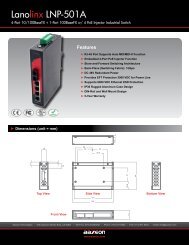
Mainboard Layout<br />
Backpanel I/O<br />
Top : mouse<br />
Bottom:<br />
keyboard<br />
J2<br />
J1<br />
DIMM2<br />
DIMM1<br />
JPW1<br />
COM Ports<br />
Top: LAN Jack<br />
Bottom: USB ports<br />
Top: LAN Jack<br />
Bottom: USB ports<br />
BATT<br />
+<br />
J4<br />
ATX1<br />
Top: VGA Port J3<br />
Bottom: HDMI<br />
T: Line-In/ SS-Out<br />
M: Line-Out<br />
B: Mic<br />
T:RS-Out<br />
M:CS-Out<br />
B:SPDIF Out<br />
JAUD1<br />
ALC888<br />
JLDVS1<br />
JTV1<br />
AMD<br />
<strong>RS690T</strong><br />
JUSB2<br />
JUSB1<br />
PCI1<br />
SB600<br />
SATA1<br />
SATA2<br />
JBAT1<br />
JCASE1<br />
Winbond<br />
W83627DHG<br />
CON1<br />
JLPT1 IDEB1<br />
JFP1<br />
CPUFAN1<br />
SYSFAN1<br />
<strong>Fuzzy</strong> <strong>RS690T</strong> (MS-9804 v1.X) Mini ITX Mainboard<br />
1-5
MS-9804 Mainboard<br />
Power Consumption<br />
Component<br />
CPU<br />
DDR2<br />
HDD<br />
ODD<br />
Description<br />
AMD Athlon 64 x2 Dual Core 2G<br />
1024MB DDR2 533 *2<br />
Maxtor 80G<br />
NEC DVD-Multi Record ND-4550A<br />
MS-9804 12Vp 12V 5V 3.3V 5VSB -12V W<br />
AMD ThermNow! Utility 4.2 0.81 3.03 1.08 0.032 0.028 79.33<br />
Particle Fuly + VCD + Xcopy 3.07 1.01 4.66 1.07 0.039 0.02 76.226<br />
3Dmark 2005 2.81 0.84 4.27 1.06 0.04 0.042 69.352<br />
Idle 0.82 0.81 3.09 1.17 0.024 0.017 39.195<br />
S3 0 0 0 0 0.512 0 2.56<br />
1-6
Product Overview<br />
Safety compliance & MTBF<br />
Safety compliance<br />
Certification<br />
CE<br />
BSMI<br />
C-Tick<br />
FCC<br />
VCCI<br />
EN 55022:1998+A1:2000+A2:2003 Class B<br />
Title of standard<br />
Product family standard<br />
Limits for harmonic current<br />
EN 6100-3-2:2000 Class D<br />
RFI<br />
emission<br />
Limitation of voltage fluctuation<br />
EN 6100-3-3:1995+A1:2001<br />
and flicker in low-voltage supply<br />
system<br />
Immunity EN 55024:1998+A1:2001+A2:2003 Product family standard<br />
CNS 13438 乙 類 (2006 年 版 )<br />
AS/NZS CISPR 22:2004<br />
FCC CFR Title 47 Part 15 Subpart B: 2005 Class B<br />
CISPR 22: 2005<br />
VCCI V-3:2004, Class B<br />
VCCI V-4:2004, Class B<br />
Standard number<br />
MTBF - Reliability Prediction<br />
Calculation Operation Operating Duty Cycle MTBF(hr.)<br />
Model<br />
temperature(°C) Environment<br />
Telcordia Issue 1 35 GF, GU - Ground 100% 93,411<br />
Fixed,<br />
Uncontrolled<br />
Telcordia Issue 1 55 GF, GU - Ground 100% 52,174<br />
Fixed,<br />
Uncontrolled<br />
1-7
MS-9804 Mainboard<br />
Board Dimension<br />
1-8
Product Overview<br />
Back Panel & I/O Shield Drawing<br />
1-9
Hardware Setup<br />
Chapter 2<br />
Hardware Setup<br />
This chapter provides you with the information about<br />
hardware setup procedures. While doing the installation,<br />
be careful in holding the components and follow the<br />
installation procedures. For some components, if you<br />
install in the wrong orientation, the components will not<br />
work properly.<br />
Use a grounded wrist strap before handling computer<br />
components. Static electricity may damage the<br />
components.<br />
2-1
MS-9804 Mainboard<br />
Quick Components Guide<br />
Back Panel,<br />
p.2-8<br />
J1~J2,<br />
p.2-16<br />
DIMM1~2,<br />
p.2-3<br />
CPU,<br />
p.2-4<br />
J4, p.2-15<br />
JPW1,<br />
p.2-7<br />
ATX1,<br />
p.2-7<br />
IDEB1, p.2-10<br />
J3, p.2-16<br />
JLVDS1,<br />
p.2-15<br />
JAUD1, p.2-12<br />
PCI1, p.2-17<br />
JUSB1~2, p.2-14<br />
JFP1, p.2-12<br />
JLPT1, p.2-13<br />
JCASE1,<br />
p.2-11<br />
Mini PCIE, p.2-17<br />
SYSFAN1, p.2-13<br />
CPUFAN1, p.2-13<br />
SATA1~2,<br />
p.2-11<br />
JTV1, p.2-14<br />
JBAT1,<br />
p.2-16<br />
2-2
Hardware Setup<br />
Memory<br />
The mainboard provides two 200-pin unbuffered DDR2 400/533/667/800 SO-DIMM<br />
slots and supports up to 4GB system memory.<br />
DIMM2<br />
200-pin, unbuffered<br />
DIMM1<br />
200-pin, unbuffered<br />
Installing Memory Modules<br />
1. The memory module has only one notch on the center and will only fit in the right<br />
orientation.<br />
2. Insert the memory module vertically into the SO-DIMM slot. Then push it in until the<br />
golden finger on the memory module is deeply inserted in the SO-DIMM slot.<br />
Important<br />
You can barely see the golden finger if the memory module is properly inserted<br />
in the DIMM slot.<br />
3. The clip at each side of the SO-DIMM slot will automatically close.<br />
Important<br />
To ensure the installations of memory and CPU successfully, please note that<br />
to insert the memory modules first before install CPU and cooler set. And<br />
please always insert the memory module into the DIMM2 first.<br />
2-3
MS-9804 Mainboard<br />
CPU (Central Processing Unit)<br />
The mainboard supports AMD ® Athlon64/ 64x2 & Sempron processors. The mainboard<br />
uses a CPU socket called Socket AM2 for easy CPU installation. When you are<br />
installing the CPU, make sure the CPU has a heat sink and a cooling fan<br />
attached on the top to prevent overheating. If you do not have the heat sink and<br />
cooling fan, contact your dealer to purchase and install them before turning on the<br />
computer.<br />
Important<br />
Overheating<br />
Overheating will seriously damage the CPU and system. Always make sure<br />
the cooling fan can work properly to protect the CPU from overheating. Make<br />
sure that you apply an even layer of thermal paste (or thermal tape) between<br />
the CPU and the heatsink to enhance heat dissipation.<br />
Replaceing the CPU<br />
While replacing the CPU, always turn off the ATX power supply or unplug the<br />
power supply’s power cord from the grounded outlet first to ensure the safety<br />
of CPU.<br />
2-4
Hardware Setup<br />
CPU Installation Procedures for Socket AM2<br />
1. Please turn off the power and<br />
unplug the power cord before<br />
installing the CPU.<br />
2. Pull the lever sideways away<br />
from the socket. Make sure to<br />
raise the lever up to a 90-degree<br />
angle.<br />
Sliding<br />
Plate<br />
Open Lever<br />
90 degree<br />
3. Look for the gold arrow of the<br />
CPU. The gold arrow should<br />
point as shown in the picture.<br />
The CPU can only fit in the correct<br />
orientation.<br />
Gold arrow<br />
4. If the CPU is correctly installed,<br />
the pins should be completely<br />
embedded into the socket and<br />
can not be seen. Please note<br />
that any violation of the correct<br />
installation procedures may<br />
cause permanent damages to<br />
your mainboard.<br />
Gold arrow<br />
Gold arrow<br />
Correct CPU placement<br />
O<br />
Incorrect CPU placement<br />
5. Press the CPU down firmly into<br />
the socket and close the lever.<br />
As the CPU is likely to move while<br />
the lever is being closed, always<br />
close the lever with your<br />
fingers pressing tightly on top of<br />
the CPU to make sure the CPU is<br />
properly and completely embedded<br />
into the socket.<br />
Press down<br />
the CPU<br />
Close<br />
Lever<br />
2-5
MS-9804 Mainboard<br />
Installing AMD Socket AM2 CPU Cooler Set<br />
When you are installing the CPU, make sure the CPU has a heat sink and a<br />
cooling fan attached on the top to prevent overheating. If you do not have the<br />
heat sink and cooling fan, contact your dealer to purchase and install them before<br />
turning on the computer.<br />
Important<br />
Mainboard photos shown in this section are for demonstration of the cooler<br />
installation for Socket AM2 CPUs only. The appearance of your mainboard<br />
may vary depending on the model you purchase.<br />
1. Position the cooling set onto the retention<br />
mechanism.<br />
Hook one end of the clip to hook<br />
first.<br />
2. Then press down the other end of<br />
the clip to fasten the cooling set on<br />
the top of the retention mechanism.<br />
Locate the Fix Lever and lift up it .<br />
Fixed Lever<br />
3. Fasten down the lever. 4. Attach the CPU Fan cable to the CPU<br />
fan connector on the mainboard.<br />
2-6
Hardware Setup<br />
Power Supply<br />
ATX 20-Pin System Power Connector: ATX1<br />
This connector allows you to connect to an ATX power supply. To connect to the ATX<br />
power supply, make sure the plug of the power supply is inserted in the proper<br />
orientation and the pins are aligned. Then push down the power supply firmly into the<br />
connector.<br />
ATX1<br />
10 20<br />
1 11<br />
PIN<br />
ATX1 Pin Definition<br />
SIGNAL<br />
1 3.3V<br />
2 3.3V<br />
3 GND<br />
4 5V<br />
5 GND<br />
6 5V<br />
7 GND<br />
8 PW_OK<br />
9 5V_SB<br />
10 12V<br />
PIN<br />
SIGNAL<br />
11 3.3V<br />
12 -12V<br />
13 GND<br />
14 PS_ON<br />
15 GND<br />
16 GND<br />
17 GND<br />
18 -5V<br />
19 5V<br />
20 5V<br />
ATX 12V Power Connector: JPW1<br />
This 12V power connector JPW1 is used to provide power to the CPU.<br />
Pin Definition<br />
1 3<br />
2 4<br />
JPW1<br />
PIN<br />
SIGNAL<br />
1 GND<br />
2 GND<br />
3 12V<br />
4 12V<br />
Important<br />
Power supply of 350watts (and above) is highly recommended for system<br />
stability.<br />
2-7
MS-9804 Mainboard<br />
Back Panel<br />
Mouse<br />
Serial Port LAN LAN VGA Port<br />
Line-In/<br />
SS-Out<br />
RS-Out<br />
Line-Out CS-Out<br />
Keyboard<br />
Serial Port<br />
USB<br />
USB<br />
HDMI Port<br />
Mic-In SPDIF-Out<br />
Mouse/Keyboard Connector<br />
The standard PS/2 ® mouse/keyboard DIN connector is for a PS/2 ® mouse/keyboard.<br />
Serial Port<br />
The serial port is a 16550A high speed communications port that sends/ receives 16<br />
bytes FIFOs. You can attach a serial mouse or other serial devices directly to the<br />
connector.<br />
LAN (RJ-45) Jacks<br />
The standard RJ-45 jacks are for<br />
connection to Local Area Network (LAN).<br />
You can connect network cables to them.<br />
Activity Indicator<br />
Link Indicator<br />
Left LED<br />
Right LED<br />
Active LED 100M/1000M Speed LED<br />
LED Color Yellow Green/Orange<br />
10M Cable Plug-in No Transmission OFF OFF<br />
Transition Yellow(Blinking) OFF<br />
100M Cable Plug-in No Transmission OFF Green(Lighting)<br />
Transition Yellow(Blinking) Green(Lighting)<br />
1000M Cable Plug-in No Transmission OFF Orange(Lighting)<br />
Transition Yellow(Blinking) Orange(Lighting)<br />
In S3/S4/S5 Standby State OFF OFF<br />
USB Connectors<br />
The UHCI (Universal Host Controller Interface) Universal Serial Bus root is for attaching<br />
USB devices such as keyboard, mouse, or other USB-compatible devices.<br />
2-8
Hardware Setup<br />
VGA Port<br />
The DB15-pin female connector is provided for video monitors.<br />
HDMI Port<br />
The High-Definition Multimedia Interface (HDMI) is an all-digital audio/video interface<br />
capable of transmitting uncompressed streams. HDMI supports all TV format, including<br />
standard, enhanced, or high-definition video, plus multi-channel digital audio on a<br />
single cable.<br />
Audio Port Connectors<br />
These audio connectors are used for audio devices. You can differentiate the color<br />
of the audio jacks for different audio sound effects.<br />
Line-In/ SS-Out (Blue) - Line In / Side-Surround Out in 7.1 channel mode,<br />
is used for external CD player, tapeplayer or other<br />
audio devices.<br />
Line-Out (Green) - Line Out, is a connector for speakers or headphones.<br />
Mic (Pink) - Mic, is a connector for microphones.<br />
RS-Out (Black) - Rear-Surround Out in 4/ 5.1/ 7.1 channel mode.<br />
CS-Out (Orange) - Center/ Subwoofer Out in 5.1/ 7.1 channel mode.<br />
Optical S/PDIF-Out connector<br />
This SPDIF (Sony & Philips Digital Interconnect Format) connector is provided for<br />
digital audio transmission to external speakers through a fiber cable.<br />
2-9
MS-9804 Mainboard<br />
Connectors<br />
IDE Connector: IDEB1<br />
The mainboard has a 32-bit Enhanced PCI IDE and Ultra DMA 33/66/100/133 controller<br />
that provides PIO mode 0~4, Bus Master, and Ultra DMA 33/66/100/133 function. You<br />
can connect hard disk drives, CD-ROM and other IDE devices.<br />
The Ultra ATA133 interface boosts data transfer rates between the computer and the<br />
hard drive up to 133 megabytes (MB) per second.<br />
IDEB1<br />
Important<br />
If you install two IDE devices, you must configure the second drive to Slave<br />
mode by setting its jumper. Refer to the hard disk documentation supplied by<br />
hard disk vendors for jumper setting instructions.<br />
2-10
Hardware Setup<br />
Serial ATA Connectors: SATA1, SATA2<br />
SATA1~SATA2 are high-speed SATA interface ports and support SATA data rates of<br />
300MB/s. Each SATA connector can connect to 1 hard disk device and is fully compliant<br />
with Serial ATA 2.0 specifications.<br />
SATA1<br />
SATA2<br />
Important<br />
Please do not fold the Serial ATA cable into 90-degree angle. Otherwise,<br />
data loss may occur during transmission.<br />
Chassis Intrusion Connector: JCASE1<br />
This connector connects to the chassis intrusion switch cable. If the chassis is<br />
opened, the chassis intrusion mechanism will be activated. The system will record<br />
this status and show a warning message on the screen. To clear the warning, you<br />
must enter the BIOS utility and clear the record.<br />
1 CINTRU<br />
2 GND<br />
JCASE1<br />
2-11
-<br />
-<br />
-<br />
MS-9804 Mainboard<br />
Audio Amplifier Connector: JAUD1<br />
The 6W JAUD1 is used to connect audio amplifiers to enhance audio performance.<br />
Pin Definition<br />
JAUD1 PIN SIGNAL<br />
1<br />
1 AMP_R+<br />
2 AMP_R-<br />
3 AMP_L+<br />
4 AMP_L-<br />
Front Panel Connector: JFP1<br />
The mainboard provides one front panel connector for electrical connection to the<br />
front panel switches and LEDs. The JFP1 is compliant with Intel ® Front Panel I/O<br />
Connectivity Design Guide.<br />
Power<br />
LED<br />
Power<br />
Switch<br />
+<br />
JFP1 1 2 9 10<br />
+<br />
+<br />
HDD<br />
LED Reset<br />
Switch<br />
JFP1 Pin Definition<br />
PIN SIGNAL DESCRIPTION<br />
1 HD_LED + Hard disk LED pull-up<br />
2 FP PWR/SLP Power LED pull-up<br />
3 HD_LED - Hard disk active LED<br />
4 FP PWR/SLP Power LED pull-up<br />
5 RST_SW - Reset Switch low reference pull-down to GND<br />
6 PWR_SW + Power Switch high reference pull-up<br />
7 RST_SW + Reset Switch high reference pull-up<br />
8 PWR_SW - Power Switch low reference pull-down to GND<br />
9 RSVD_DNU Reserved. Do not use.<br />
2-12
Hardware Setup<br />
Fan Power Connectors: CPUFAN1, SYSFAN1<br />
The fan power connectors support system cooling fan with +12V. When connecting<br />
the wire to the connectors, always take note that the red wire is the positive and<br />
should be connected to the +12V, the black wire is Ground and should be connected<br />
to GND. If the mainboard has a System Hardware Monitor chipset on-board, you must<br />
use a specially designed fan with speed sensor to take advantage of the CPU fan<br />
control.<br />
GND<br />
+12V<br />
SENSOR<br />
Control<br />
GND<br />
+12V<br />
SENSOR<br />
CPUFAN1<br />
SYSFAN1<br />
Important<br />
Please refer to the recommended CPU fans at A D’s official website or consult<br />
the vendors for proper CPU cooling fan.<br />
Parallel Port Header: JLPT1<br />
The mainboard provides a 26-pin header for connection to an optional parallel port<br />
bracket. The parallel port is a standard printer port that supports Enhanced Parallel<br />
Port (EPP) and Extended Capabilities Parallel Port (ECP) mode.<br />
2625<br />
JLPT1<br />
Parallel Port<br />
Bracket (Optional)<br />
21<br />
PIN SIGNAL PIN SIGNAL<br />
1 RSTB# 2 AFD#<br />
3 PRND0 4 ERR#<br />
5 PRND1 6 PINIT#<br />
7 PRND2 8 LPT_SLIN#<br />
9 PRND3 10 GND<br />
11 PRND4 12 GND<br />
13 PRND5 14 GND<br />
PIN SIGNAL PIN SIGNAL<br />
15 PRND6 16 GND<br />
17 PRND7 18 GND<br />
19 ACK# 20 GND<br />
21 BUSY 22 GND<br />
23 PE 24 GND<br />
25 SLCT 26 GND<br />
2-13
MS-9804 Mainboard<br />
Front USB Connector: JUSB1/ JUSB2<br />
The USB 2.0 pinheader is compliant with Intel ® I/O Connectivity Design Guide. USB 2.<br />
0 technology increases data transfer rate up to a maximum throughput of 480Mbps,<br />
which is 40 times faster than USB 1.1, and is ideal for connecting high-speed USB<br />
interface peripherals such as USB HDD, digital cameras, MP3 players, printers,<br />
modems and the like.<br />
Pin Definition<br />
2 10<br />
1 9<br />
JUSB1/ 2<br />
PIN SIGNAL PIN SIGNAL<br />
1 VCC 2 VCC<br />
3 USB0- 4 USB1-<br />
5 USB0+ 6 USB1+<br />
7 GND 8 GND<br />
9 Key (no pin) 10 NC<br />
Important<br />
Note that the pins of VCC and GND must be connected correctly to avoid<br />
possible damage.<br />
TV-Out Connector: JTV1<br />
The mainboard provides a TV-Out connector.<br />
JTV1<br />
3<br />
4 1<br />
Display Matrix<br />
CRT HDMI LVDS TV OUT<br />
CRT X V X<br />
HDMI X V X<br />
LVDS V V V<br />
TV OUT X X V<br />
JTV1 Pin Definition<br />
Pin Description Pin Description<br />
1 GND 2 Y_L<br />
3 C_L 4 COMP_L<br />
5 GND 6 Key (no pin )<br />
V : Support<br />
X : No Support<br />
2-14
Hardware Setup<br />
LVDS Flat Panel Connector: JLVDS1<br />
The LVDS (Low Voltage Differential Signal)<br />
connector provides a digital interface typically<br />
used with flat panels. After connecting an<br />
LVDS interfaced flat panel to the JLVDS1, be<br />
sure to check the panel datasheet and set the<br />
J1 LVDS Power Selection Jumper to a proper<br />
voltage.<br />
Display Matrix<br />
CRT HDMI LVDS TV OUT<br />
CRT X V X<br />
HDMI X V X<br />
LVDS V V V<br />
TV OUT X X V<br />
V : Support<br />
X : No Support<br />
39 40<br />
1 2<br />
JLVDS1<br />
SIGNAL PIN SIGNAL<br />
+12V 2 1 +12V<br />
+12V 4 3 +12V<br />
GND 6 5 +12V<br />
GND 8 7 VCC3/VCC5<br />
LCD_VDD 10 9 LCD_VDD<br />
LDDC_DATA 12 11 LDDC_CLK<br />
LVDS_VDDEN 14 13 L_BKLTCTL<br />
GND 16 15 L_BKLTEN<br />
LA_DATA0 18 17 LA_DATA0#<br />
LA_DATA1 20 19 LA_DATA1#<br />
LA_DATA2 22 21 LA_DATA2#<br />
LA_CLK 24 23 LA_CLK#<br />
LA_DATA3 26 25 LA_DATA3#<br />
GND 28 27 GND<br />
LB_DATA0 30 29 LB_DATA0#<br />
LB_DATA1 32 31 LB_DATA1#<br />
LB_DATA2 34 33 LB_DATA2#<br />
LB_CLK 36 35 LB_CLK#<br />
LB_DATA3 38 37 LB_DATA3#<br />
GND 40 39 GND<br />
I2C Bus Connector: J4<br />
The mainboard provides one I2C (also known as I 2 C) Bus connector for users to<br />
connect System Management Bus (SMBus) interface.<br />
Pin Definition<br />
J4<br />
4<br />
1<br />
Pin Signal<br />
1 VCC5F<br />
2 SMBCLK<br />
3 GND<br />
4 SMBDATA<br />
2-15
MS-9804 Mainboard<br />
Jumpers<br />
COM Port Power Jumpers: J1, J2<br />
These jumpers specify the operation voltage of the onboard serial ports.<br />
J2<br />
J1<br />
1<br />
1<br />
+12V +5V<br />
1<br />
Clear CMOS Jumper: JBAT1<br />
There is a CMOS RAM onboard that has a power supply from external battery to keep<br />
the data of system configuration. With the CMOS RAM, the system can automatically<br />
boot OS every time it is turned on. If you want to clear the system configuration, set<br />
this jumper to clear data.<br />
1<br />
1<br />
1<br />
JBAT1<br />
3<br />
Keep Data<br />
3<br />
Clear Data<br />
Important<br />
You can clear CMOS by shorting 2-3 pin while the system is off. Then return<br />
to 1-2 pin position. Avoid clearing the CMOS while the system is on; it will<br />
damage the mainboard.<br />
LVDS Power Selection Jumper: J3<br />
Use this jumper to specify the operation voltage of the LVDS interfaced flat panel.<br />
J3<br />
1<br />
1<br />
1<br />
+3V +5V<br />
2-16
Hardware Setup<br />
Slots<br />
Mini PCI (Peripheral Component Interconnect) Express Slot<br />
The CON1 is Mini PCI-E connector for wireless LAN, TV tuner, and Robson NAND<br />
Flash.<br />
Mini PCI-E Slot<br />
PCI (Peripheral Component Interconnect) Slot<br />
The PCI slot supports LAN card, SCSI card, USB card, and other add-on cards that<br />
comply with PCI specifications.<br />
32-bit PCI Slot<br />
PCI Interrupt Request Routing<br />
The IRQ, acronym of interrupt request line and pronounced I-R-Q, are hardware lines<br />
over which devices can send interrupt signals to the microprocessor. The PCI IRQ<br />
pins are typically connected to the PCI bus pins as follows:<br />
DEVICE IDSEL INT A INTB INTC INTD REQ# / GNT#<br />
32-bit PCI Slot AD18 E F G H REQ#0 / GNT#0<br />
Important<br />
When adding or removing expansion cards, make sure that you unplug the<br />
power supply first. Meanwhile, read the documentation for the expansion card<br />
to configure any necessary hardware or software settings for the expansion<br />
card, such as jumpers, switches or BIOS configuration.<br />
2-17
BIOS Setup<br />
Chapter 3<br />
BIOS Setup<br />
This chapter provides information on the BIOS Setup<br />
program and allows you to configure the system for<br />
optimum use.<br />
You may need to run the Setup program when:<br />
† An error message appears on the screen during the<br />
system booting up, and requests you to run SETUP.<br />
† You want to change the default settings for customized<br />
features.<br />
3-1
MS-9804 Mainboard<br />
Entering Setup<br />
Power on the computer and the system will start POST (Power On Self Test) process.<br />
When the message below appears on the screen, press key to enter Setup.<br />
Press Del to enter SETUP<br />
If the message disappears before you respond and you still wish to enter Setup,<br />
restart the system by turning it OFF and On or pressing the RESET button. You may<br />
also restart the system by simultaneously pressing , , and keys.<br />
Important<br />
1. The items under each BIOS category described in this chapter are under<br />
continuous update for better system performance. Therefore, the description<br />
may be slightly different from the latest BIOS and should be held for<br />
reference only.<br />
2. Upon boot-up, the 1st line appearing after the memory count is the BIOS<br />
version. It is usually in the format:<br />
A9804KMS V1.0 071807 where:<br />
1st digit refers to BIOS maker as A = AMI, W = AWARD, and P =<br />
PHOENIX.<br />
2nd - 5th digit refers to the model number.<br />
6th digit refers to the chipset as I = Intel, N = nVidia, A = ATi , K=AMD<br />
and V = VIA.<br />
7th - 8th digit refers to the customer as MS = all standard customers.<br />
V1.0 refers to the BIOS version.<br />
071807 refers to the date this BIOS was released.<br />
3-2
BIOS Setup<br />
Control Keys<br />
<br />
<br />
<br />
<br />
<br />
<br />
<br />
<br />
<br />
<br />
<br />
Move to the previous item<br />
Move to the next item<br />
Move to the item in the left hand<br />
Move to the item in the right hand<br />
Select the item<br />
Jumps to the Exit menu or returns to the main menu from a<br />
submenu<br />
Increase the numeric value or make changes<br />
Decrease the numeric value or make changes<br />
Load Optimized Defaults<br />
Load Fail-Safe Defaults<br />
Save all the CMOS changes and exit<br />
Getting Help<br />
After entering the Setup menu, the first menu you will see is the Main Menu.<br />
Main Menu<br />
The main menu lists the setup functions you can make changes to. You can use the<br />
arrow keys ( ↑↓ ) to select the item. The on-line description of the highlighted setup<br />
function is displayed at the bottom of the screen.<br />
Sub-Menu<br />
If you find a right pointer symbol (as shown in the right view) appears to the left of<br />
certain fields that means a sub-menu can be launched from this<br />
field. A sub-menu contains additional options for a field parameter.<br />
You can use arrow keys ( ↑↓ ) to highlight the field and press<br />
to call up the sub-menu. Then you can use the control keys to enter values<br />
and move from field to field within a sub-menu. If you want to return to the main<br />
menu, just press the .<br />
General Help <br />
The BIOS setup program provides a General Help screen. You can call up this screen<br />
from any menu by simply pressing . The Help screen lists the appropriate keys<br />
to use and the possible selections for the highlighted item. Press to exit the<br />
Help screen.<br />
3-3
MS-9804 Mainboard<br />
The Menu Bar<br />
Main<br />
Use this menu for basic system configurations, such as time, date etc.<br />
Advanced<br />
Use this menu to set up the items of special enhanced features.<br />
PCIPnP<br />
This entry appears if your system supports PnP/PCI.<br />
Boot<br />
Use this menu to specify the priority of boot devices.<br />
Security<br />
Use this menu to set supervisor and user passwords.<br />
Chipset<br />
This menu controls the advanced features of the onboard Northbridge and Southbridge.<br />
Power<br />
Use this menu to specify your settings for power management.<br />
Exit<br />
This menu allows you to load the BIOS default values or factory default settings into<br />
the BIOS and exit the BIOS setup utility with or without changes.<br />
3-4
BIOS Setup<br />
Main<br />
AMI BIOS, Processor, System Memory<br />
These items show the firmware and hardware specifications of your system. Read<br />
only.<br />
System Time<br />
The time format is .<br />
System Date<br />
The date format is , .<br />
3-5
MS-9804 Mainboard<br />
Advanced<br />
CPU Configuration<br />
These items show the advanced specifications of your CPU. Read only.<br />
3-6
BIOS Setup<br />
IDE Configuration<br />
OnBoard PCI IDE Controller<br />
This setting is used to enable/ disable the IDE controller.<br />
Primary/Secondary/Third/Fourth IDE Master/Slave<br />
3-7
MS-9804 Mainboard<br />
[Type]<br />
Press PgUp/ or PgDn/ to select<br />
[Manual], [None] or [Auto] type. Note that the<br />
specifications of your drive must match with<br />
the drive table. The hard disk will not work<br />
properly if you enter improper information for<br />
this category. If your hard disk drive type is<br />
not matched or listed, you can use [Manual] to<br />
define your own drive type manually.<br />
[LBA/Large Mode]<br />
Enabling LBA causes Logical Block Addressing<br />
to be used in place of Cylinders,<br />
Heads and Sectors<br />
[Block(Multi-Sector Transfer)] Any selection except Disabled determines<br />
the number of sectors transferred per block<br />
[PIO Mode]<br />
Indicates the type of PIO (Programmed Input/<br />
Output)<br />
[DMA Mode]<br />
Indicates the type of Ultra DMA<br />
[S.M.A.R.T.]<br />
This allows you to activate the S.M.A.R.T.<br />
(Self-Monitoring Analysis & Reporting<br />
Technology) capability for the hard disks. S.<br />
M.A.R.T is a utility that monitors your disk sta<br />
tus to predict hard disk failure. This gives you<br />
an opportunity to move data from a hard disk<br />
that is going to fail to a safe place before the<br />
hard disk becomes offline.<br />
[32 Bit Data Transfer] Enables 32-bit communication between<br />
CPU and IDE card<br />
Super IO Configuration<br />
3-8
BIOS Setup<br />
Serial Port 1 / 2 Address<br />
Select an address and a corresponding interrupt for the serial port 1/2.<br />
Serial Port2 Mode Select<br />
This setting allows you to specify the operation mode for serial port 2.<br />
[Normal] RS-232C Serial Port<br />
[IrDA] IrDA-compliant Serial Infrared Port<br />
[ASKIR] Amplitude Shift Keyed Infrared Port<br />
Parallel Port Address<br />
This setting specifies the I/O port address and IRQ of the onboard parallel port.<br />
Parallel Port Mode<br />
[Normal] Standard Parallel Port<br />
[EPP]<br />
Enhanced Parallel Port<br />
[ECP]<br />
Extended Capability Port<br />
[ECP + EPP] Extended Capability Port + Enhanced Parallel<br />
To operate the onboard parallel port as Standard Parallel Port only,<br />
[Normal]. To operate the onboard parallel port in the EPP mode simultaneously,<br />
choose [EPP]. By choosing [ECP], the onboard parallel port will ECP mode<br />
only. Choosing [ECP + EPP] will allow the onboard parallel support both the<br />
ECP and EPP modes simultaneously.<br />
Parallel Port IRQ<br />
This item allows you to set parallel port IRQ.<br />
Hardware Health Configuration<br />
3-9
MS-9804 Mainboard<br />
System Temperature, CPU Temperature, SYSFAN Speed, Vcore, AVCC,<br />
3VCC, +5VIN, +12VIN, VSB, VBAT<br />
These items display the current status of all of the monitored hardware devices/components<br />
such as CPU voltage, temperatures and all fans’ speeds.<br />
ACPI Settings<br />
General ACPI Configuration<br />
3-10
BIOS Setup<br />
Suspend Mode<br />
This item specifies the power saving modes for ACPI function. If your operating<br />
system supports ACPI, you can choose to enter the Standby mode in S1 (POS)<br />
or S3 (STR) fashion through the setting of this field. Options are:<br />
[S1 (POS)] The S1 sleep mode is a low power state. In this state,<br />
no system context is lost (CPU or chipset) and hardware<br />
maintains all system context.<br />
[S3 (STR)] The S3 sleep mode is a lower power state where the<br />
information of system configuration and open applications/files<br />
is saved to main memory that remains<br />
powered while most other hardware components turn<br />
off to save energy. The information stored in memory<br />
will be used to restore the system when a “wake up”<br />
event occurs.<br />
[Auto] Auto arrange.<br />
Repost Video on S3 Resume<br />
Selecting [Yes] allows BIOS to call VGABIOS to initialize the VGA card when<br />
system wakes up (resumes) from S3 sleep state. The system resume time is<br />
shortened when you disable the function, but system will need an video<br />
driver to initialize the graphics card. Therefore, if the video driver of the card<br />
does not support the initialization feature, the display may work abnormally or<br />
not function after resuming from S3.<br />
Advanced ACPI Configuration<br />
ACPI Version Features<br />
This setting allows you to select the ACPI version.<br />
3-11
MS-9804 Mainboard<br />
MPS Configuration<br />
MPS Revision<br />
This field allows you to select which MPS (Multi-Processor Specification) version<br />
to be used for the operating system. You need to select the MPS version<br />
supported by your operating system. To find out which version to use, consult<br />
the vendor of your operating system.<br />
Smbios Configuration<br />
3-12
BIOS Setup<br />
Smbios Smi Support<br />
SMBIOS SMI wrapper supports the PnP function :50h-54h.<br />
Trusted Computing<br />
TCG/TPM SUPPORT<br />
This setting controls the Trusted Platform Module (TPM) designed by the Trusted<br />
Computing Group (TCG). TPMs are special-purpose integrated circuits (ICs)<br />
built into a variety of platforms to enable strong user authentication and machine<br />
attestation—essential to prevent inappropriate access to confidential<br />
andsensitiveinformationandtoprotect against compromised networks.<br />
3-13
MS-9804 Mainboard<br />
USB Configuration<br />
USB Legacy Support<br />
Set to [Enabled] if your need to use any USB device in the operating system<br />
that does not support or have any USB driver installed, such as DOS and<br />
SCO Unix. Set to [Disabled] only if you want to use any USB device other<br />
than the USB mouse.<br />
USB 2.0 controller mode<br />
Use this field to select the USB 2.0 mode.<br />
3-14
BIOS Setup<br />
PCIPnP<br />
This section describes configuring the PCI bus system and PnP (Plug & Play) feature.<br />
PCI, or Peripheral Component Interconnect, is a system which allows I/O devices to<br />
operate at speeds nearing the speed the CPU itself uses when communicating with<br />
its special components. This section covers some very technical items and it is<br />
strongly recommended that only experienced users should make any changes to the<br />
default settings.<br />
Clear NVRAM<br />
The ESCD (Extended System Configuration Data) NVRAM (Non-volatile Random Access<br />
Memory) is where the BIOS stores resource information for both PNP and non-<br />
PNP devices in a bit string format. Whent the item is set to Yes, the system will reset<br />
ESCD NVRAM right after the system is booted up and then set the setting of the item<br />
back to No automatically.<br />
Plug and Play O/S<br />
When set to [Yes], BIOS will only initialize the PnP cards used for booting (VGA, IDE,<br />
SCSI). The rest of the cards will be initialized by the PnP operating system like<br />
Windows 98, 2000 or ME. When set to [No], BIOS will initialize all the PnP cards.<br />
Select Yes if the operating system is Plug & Play.<br />
PCI Latency Timer<br />
This item controls how long each PCI device can hold the bus before another takes<br />
over. When set to higher values, every PCI device can conduct transactions for a<br />
longer time and thus improve the effective PCI bandwidth. For better PCI performance,<br />
you should set the item to higher values.<br />
3-15
MS-9804 Mainboard<br />
Boot<br />
Boot Settings Configuration<br />
Quick Boot<br />
Enabling this setting will cause the BIOS power-on self test routine to skip some<br />
of its tests during bootup for faster system boot.<br />
3-16
BIOS Setup<br />
Quiet Boot<br />
This BIOS feature determines if the BIOS should hide the normal POST messages<br />
with the motherboard or system manufacturer's full-screen logo.<br />
When it is enabled, the BIOS will display the full-screen logo during the boot-up<br />
sequence, hiding normal POST messages.<br />
When it is disabled, the BIOS will display the normal POST messages, instead of<br />
the full-screen logo.<br />
Please note that enabling this BIOS feature often adds 2-3 seconds of delay to<br />
the booting sequence. This delay ensures that the logo is displayed for a<br />
sufficient amount of time. Therefore, it is recommended that you disable this<br />
BIOS feature for a faster boot-up time.<br />
AddOn ROM Display Mode<br />
This item is used to determine the display mode when an optional ROM is<br />
initialized during POST. When set to [Force BIOS], the display mode used by AMI<br />
BIOS is used. Select [Keep Current] if you want to use the display mode of<br />
optional ROM.<br />
Bootup Num-Lock<br />
This setting is to set the Num Lock status when the system is powered on.<br />
Setting to [On] will turn on the Num Lock key when the system is powered on.<br />
Setting to [Off] will allow users to use the arrow keys on the numeric keypad.<br />
PS/2 Mouse Support<br />
Select [Enabled] if you need to use a PS/2-interfaced mouse in the operating<br />
system.<br />
3-17
MS-9804 Mainboard<br />
Security<br />
Supervisor Password / Change Supervisor Password<br />
Supervisor Password controls access to the BIOS Setup utility. These settings allow<br />
you to set or change the supervisor password.<br />
User Password / Change User Password<br />
User Password controls access to the system at boot. These settings allow you to<br />
set or change the user password.<br />
Boot Sector Virus Protection<br />
This function protects the BIOS from accidental corruption by unauthorized users or<br />
computer viruses. When enabled, the BIOS’ data cannot be changed when attempting<br />
to update the BIOS with a Flash utility. To successfully update the BIOS, you’ll<br />
need to disable this Flash BIOS Protection function.<br />
You should enable this function at all times. The only time when you need to disable<br />
it is when you want to update the BIOS. After updating the BIOS, you should immediately<br />
re-enable it to protect it against viruses.<br />
Chassis Intrusion<br />
The field enables or disables the feature of recording the chassis intrusion status<br />
and issuing a warning message if the chassis is once opened. To clear the warning<br />
message, set the field to [Reset]. The setting of the field will automatically return to<br />
[Enabled] later.<br />
3-18
BIOS Setup<br />
Chipset<br />
NorthBridge Configuration<br />
These items show the DRAM timing. Read only.<br />
3-19
MS-9804 Mainboard<br />
South Bridge Configuration<br />
AC97 Audio/ Modem Device<br />
This setting is used to enable/disable the onboard AC97 audio/ modem<br />
device.<br />
USB 1.1 OCHI Controllers/ USB 2.0 EHCI Controller<br />
This settings allow you to enable/disable the onboard USB1.1/ 2.0 controller.<br />
OnChip SATA Channel<br />
This item is used to enable/disable the onboard SATA channel.<br />
OnChip SATA Type<br />
This item is used to specify the SATA type for SATA device.<br />
3-20
BIOS Setup<br />
AMD 690T Configuration<br />
Internal Graphics Configuration<br />
3-21
MS-9804 Mainboard<br />
Internal Graphics Mode Select<br />
The field allows you to select whether the UMA (Unified Memory Architecture)<br />
or Sideport (Local Frame Buffer) memory allocated for video memory.<br />
UMA Frame Buffer Size<br />
The field specifies the size of the system memory allocated for video memory.<br />
Current UMA Size<br />
This item shows current UMA Size.<br />
Primary Video Controller<br />
This item specifies which VGA card is your primary graphics adapter.<br />
Video Display Devices<br />
Use the field to select the type of device you want to use as the display(s)<br />
of the system.<br />
TV Standard<br />
Select the TV standard which is used as the video signal format of your TV<br />
if you have connected a TV to the system.<br />
NB Azalia<br />
This setting controls the High Definition Audio interface integrated in the<br />
Northbridge.<br />
TMDS Support<br />
This setting is used to enable/ disable TMDS (Transition Minimized Differential<br />
Signaling) technology.<br />
3-22
BIOS Setup<br />
Onboard Peripherals Configuration<br />
Spread Spectrum<br />
When the motherboard’s clock generator pulses, the extreme values (spikes)<br />
of the pulses create EMI (Electromagnetic Interference). The Spread Spectrum<br />
function reduces the EMI generated by modulating the pulses so that the<br />
spikes of the pulses are reduced to flatter curves. If you do not have any EMI<br />
problem, leave the setting at Disabled for optimal system stability and<br />
performance. But if you are plagued by EMI, set to Enabled for EMI reduction.<br />
Remember to disable Spread Spectrum if you are overclocking because even<br />
a slight jitter can introduce a temporary boost in clock speed which may just<br />
cause your overclocked processor to lock up.<br />
Important<br />
1. If you do not have any EMI problem, leave the setting at [Disabled] for<br />
optimal system stability and performance. But if you are plagued by EMI,<br />
select the value of Spread Spectrum for EMI reduction.<br />
2. The greater the Spread Spectrum value is, the greater the EMI is reduced,<br />
and the system will become less stable. For the most suitable Spread<br />
Spectrum value, please consult your local EMI regulation.<br />
3. Remember to disable Spread Spectrum if you are overclocking because<br />
even a slight jitter can introduce a temporary boost in clock speed which<br />
may just cause your overclocked processor to lock up.<br />
3-23
MS-9804 Mainboard<br />
Power<br />
Power Management/ APM<br />
Setting to Enabled will activate an Adcanced Power Management (APM) device to<br />
enhance Max Saving mode and stop CPU internal clock.<br />
Suspend Time Out<br />
If system activity is not detected for the length of time specified in this field, all<br />
devices except CPU will be shut off.<br />
Power Button Mode<br />
This feature sets the function of the power button. Settings are:<br />
[On/Off] The power button functions as normal power off button.<br />
[Suspend] When you press the power button, the computer enters the<br />
suspend/sleep mode, but if the button is pressed for more<br />
than four seconds, the computer is turned off.<br />
Video Power Down Mode<br />
This setting is used to control the mode in which the monitor will shut down. Settings<br />
are:<br />
[Always On] Monitor remains on during power-saving modes.<br />
[Suspend -> Off] Monitor blanked when system enters Suspend mode.<br />
[Susp, Stby->Off] Monitor blanked when system enters either Suspend<br />
or Standby mode.<br />
[All Modes ->Off] Monitor blanked when system enters any power sav<br />
ing mode.<br />
3-24
BIOS Setup<br />
Hard Disk Power Down Mode<br />
If HDD activity is not detected for the length of time specified in this field, the hard disk<br />
drive will be powered down while all other devices remain active.<br />
Hard Disk Time Out (Minute)<br />
After the selected period of system inactivity, the hard disk shut of.<br />
Restore on AC Power Loss<br />
This setting specifies whether your system will reboot after a power failure or<br />
interrupt occurs. Available settings are:<br />
[Power Off]<br />
Leaves the computer in the power off state.<br />
[Power On]<br />
Leaves the computer in the power on state.<br />
[Last State] Restores the system to the previous status before power<br />
failure or interrupt occurred.<br />
RTC Resume<br />
When [Enabled], your can set the date and time at which the RTC (real-time clock)<br />
alarm awakens the system from Suspend mode.<br />
3-25
MS-9804 Mainboard<br />
Exit<br />
Save Changes and Exit<br />
Save changes to CMOS and exit the Setup Utility.<br />
Discard Changes and Exit<br />
Abandon all changes and exit the Setup Utility.<br />
Discard Changes<br />
Abandon all changes and continue with the Setup Utility.<br />
Load Optimal Defaults<br />
Use this menu to load the default values set by the mainboard manufacturer specifically<br />
for optimal performance of the mainboard.<br />
Load Failsafe Defaults<br />
Use this menu to load the default values set by the BIOS vendor for stable system<br />
performance.<br />
3-26
System Resources<br />
Chapter 4<br />
System Resources<br />
This chapter provides information on the following<br />
system resources:<br />
1. Watch Dog Timer Setting (p.4-2);<br />
2. AMI POST Code (p.4-3);<br />
3. Resource List (p.4-6).<br />
4-1
MS-9804 Mainboard<br />
Watch Dog Timer Setting<br />
Software code<br />
SIO_IDX equ 4EH<br />
SIO_DTA equ 4FH<br />
Timer equ 10; reset after 10 seconds<br />
1. Enter configuration mode<br />
mov dx,SIO_IDX<br />
mov al,87h<br />
out dx,al<br />
out dx,al<br />
2. Set to LDN 08<br />
mov dx,SIO_IDX<br />
mov al,07h<br />
out dx,al<br />
mov dx,SIO_DTA<br />
mov al,08h<br />
out dx,al<br />
3. Set WatchDog Timer<br />
mov dx,SIO_IDX<br />
mov al,0f6h<br />
out dx,al<br />
mov dx,SIO_DTA<br />
mov al,Timer<br />
out dx,al<br />
4. Exit configuration mode<br />
mov dx,SIO_IDX<br />
mov al,0AAh<br />
out dx,al<br />
4-2
System Resources<br />
AMI POST Code<br />
Bootblock Initialization Code Checkpoinits<br />
The Bootblock initialization code sets up the chipset, memory and other components<br />
before system memory is available. The following table describes the type of checkpoints<br />
that may occur during the bootblock initialization portion of the BIOS:<br />
Bootblock Initialization Code Checkpoint list<br />
Checkpoint<br />
Before D1<br />
D1<br />
DO<br />
D2<br />
D3<br />
D4<br />
D5<br />
D6<br />
D7<br />
D8<br />
D9<br />
DA<br />
Description<br />
Early chipset initialization is done. Early super I/O initialization is done<br />
including RTC and keyboard controller. NMI is disabled.<br />
Perform keyboard controller BAT test. Check if waking up from power<br />
management suspend state. Save power-on CPUID value in scratch<br />
CMOS.<br />
Go to flat mode with 4GB limit and GA20 enabled. Verify the bootblock<br />
checksum.<br />
Disable CACHE before memory detection. Execute full memory sizing<br />
module. Verify that flat mode is enabled.<br />
If memory sizing module not executed, start memory refresh and do<br />
memory sizing in Bootblock code. Do additional chipset initialization.<br />
Re-enable CACHE. Verify that flat mode is enabled.<br />
Test base 512KB memory. Adjust policies and cache first 8MB. Set stack.<br />
Bootblock code is copied from ROM to lower system memory and control is<br />
given to it. BIOS now executes out of RAM.<br />
Both key sequence and OEM specific method is checked to determine if<br />
BIOS recovery is forced. Main BIOS checksum is tested. If BIOS recovery<br />
is necessary, control flows to checkpoint E0.<br />
Restore CPUID value back into register. The Bootblock- Runtime interface<br />
module is moved to system memory and control is given to it. Determine<br />
whether to execute serial flash<br />
The Runtime module is uncompressed into memory. CPUID information is<br />
stored in memory.<br />
Store the Uncompressed pointer for future use in PMM. Copying Main<br />
BIOS into memory. Leaves all RAM below 1MB Read-Write including E000<br />
and F000 shadow areas but closing SMRAM.<br />
Restore CPUID value back into register. Give control to BIOS POST<br />
(ExecutePOSTKernel.) See POST Code Checkpoint list for more<br />
information.<br />
4-3
MS-9804 Mainboard<br />
Post Code Checkpoints<br />
The POST code checkpoints are the largest set of checkpoints during the BIOS<br />
preboot process. The following table describes the type of checkpoints that may<br />
occur during the POST portion of the BIOS:<br />
Checkpoint<br />
Description<br />
03 Disable NMI, Parity, video for EGA, and DMA controllers. Initialize BIOS,<br />
POST, Runtime data area. Also initialize BIOS modules on POST entry<br />
and GPNV area. Initialized CMOS as mentioned in the Kernel Variable<br />
“Wcomsflags”.<br />
04 Check CMOS diagnostic byte to determine if battery power is OK and<br />
CMOS checksum is OK. Verify CMOS checksum manually by reading<br />
storage area. If the CMOS checksum is bad, update CMOS with<br />
power-on default values and clear passwords. Initialize status register A.<br />
Initializes data variables that are based on CMOS setup questions.<br />
Initializes both the 8259 compatible PICs in the system.<br />
05 Initializes the interrupt controlling hardware (generally PIC) and interrupt<br />
vector table.<br />
06 Do R/W test to CH-2 count reg. Initialize CH-0 as system timer. Install the<br />
POSTINT1Ch handler. Enable IRQ-0 in PIC for system timer interrupt.<br />
Traps INT1Ch vector to “POSTINT1ChHandlerBlock”.<br />
08 Initializes the CPU. The BAT test is being done on KBC.<br />
Program the keyboard controller command byte is being done after Auto<br />
detection of KB/MS using AMI KB-5.<br />
0A Initializes the 8042 compatible Key Board Controller.<br />
0B Detects the presence of PS/2 mouse.<br />
0C Detects the presence of keyboard in KBC port.<br />
0E Testing and initialization of different Input Devices. Also, update the<br />
Kernel Variables.<br />
Traps the INT09h vector, so that the POST INT09h handler gets control<br />
for IRQ1. Uncompress all available language, BIOS logo, and Silent logo<br />
modules.<br />
13 Early POST initialization of chipset registers.<br />
24 Uncompress and initialize any platform specific BIOS modules.<br />
30 Initialize System Management Interrupt.<br />
2A Initializes different devices through DIM.<br />
2C Initializes different devices. Detects and initializes the video adapter<br />
installed in the system that have optional ROMs.<br />
2E Initializes all the output devices.<br />
31 Allocate memory for ADM module and uncompress it. Give control to<br />
ADM module for initialization. Initialize language and font modules for<br />
ADM. Activate ADM module.<br />
33 Initializes the silent boot module. Set the window for displaying test<br />
information.<br />
37 Displaying sign-on message, CPU information, setup key message, and<br />
any OEM specific information.<br />
4-4
System Resources<br />
Checkpoint<br />
Description<br />
38 Initializes different devices through DIM.<br />
39 Initializes DMAC-1 & DMAC-2.<br />
3A Initializes RTC date/time.<br />
3B Test for total memory installed in the system. Also, Check for DEL or ESC<br />
keys to limit memory test. Display total memory in the system.<br />
3C Mid POST initialization of chipset registers.<br />
40 Detect different devices (Parallel ports, serial ports, and coprocessor in<br />
CPU…etc.)successfully installed in the system and update the BDA,<br />
EBDA…etc.<br />
50 Programming the memory hole or any kind of implementation that needs<br />
an adjustment in system RAM size if needed.<br />
52 Updates CMOS memory size from memory found in memory test.<br />
Allocates memory for Extended BIOS Data Area from base memory.<br />
60 Initializes NUM-LOCK status and programs the KBD typematic rate.<br />
75 Initialize Int-13 and prepare for IPL detection.<br />
78 Initializes IPL devices controlled by BIOS and option ROMs.<br />
7A Initializes remaining option ROMs.<br />
7C Generate and write contents of ESCD in NVRam.<br />
84 Log errors encountered during POST.<br />
85 Display errors to the user and gets the user response for error.<br />
87 Execute BIOS setup if needed / requested.<br />
8C Late POST initialization for chipset registers.<br />
8E Program the peripheral parameters. Enable / Disable NMI as selected.<br />
90 Late POST initialization of system management interrupt.<br />
A0 Check boot password if installed.<br />
A1 Clean-up work needed before booting to OS.<br />
A2 Takes care of runtime image preparation for different BIOS modules Fill the<br />
free area in F000h segment with 0FFh.<br />
Initializes the <strong>Micro</strong>soft IRQ Routing Table. Prepares the runtime language<br />
module. Disables the system configuration display if needed.<br />
A4 Initialize runtime language module.<br />
A7 Displays the system configuration screen if enabled. Initialize the CPU’s<br />
before boot, which includes the programming of the MTRR’s.<br />
A8 Prepare CPU for OS boot including final MTRR values.<br />
A9 Wait for user input at config display if needed.<br />
AA Uninstall POST INT1Ch vector and INT09h vector. Deinitializes the ADM<br />
module.<br />
AB Prepare BBS for 19 boot.<br />
AC End of POST initialization of chipset registers.<br />
B1 Save system contest for ACPI.<br />
00 Passes control to OS Loader (typically INT19h).<br />
4-5
MS-9804 Mainboard<br />
Resource List<br />
SB600 GPIO Config.<br />
GPIO Pin Type Multiplexed Power Function<br />
GPIO0 I/OD(3.3V) NA Main NC<br />
GPIO1 I/O(3.3V) NA Main NC<br />
GPIO2 I/O(3.3V) NA Main NC<br />
GPIO3 I/O(3.3V) NA Main NC<br />
GPIO4 I/O(3.3V) NA Main NC<br />
GPIO5 I/O(3.3V) NA Main NC<br />
GPIO6 I/OD(3.3V) NA Main NC<br />
GPIO7 I/O(3.3V) NA Main NC<br />
GPIO8 I/O(3.3V) NA Main NC<br />
GPIO9 I/O(3.3V) NA Main IDE Cable Dectec<br />
GPIO10 I/O(3.3V) NA Main NC<br />
GPIO11 I/O(S5_3.3V) SPI_DO Standby SPI_DO<br />
GPIO12 I/O(S5_3.3V) SPI_DI Standby SPI_DI<br />
GPIO13 O(3.3V) NA Main NC<br />
GPIO14 I/O(3.3V) NA Main NC<br />
GPIO[ 15..30 ] I/O(3.3V) IDE_D [ 0..15 ] Main IDE_D [ 0..15 ]<br />
GPIO31 I/O(S5_3.3V) SPI_HOLD# Standby SPI_HOLD#<br />
GPIO32 I/O(S5_3.3V) SPI_CS# Standby SPI_CS#<br />
GPIO33 I/O(3.3V) INTE# Main INTE#<br />
GPIO34 I/O(3.3V) INTE# Main INTE#<br />
GPIO35 I/O(3.3V) INTE# Main INTE#<br />
GPIO36 I/O(3.3V) INTE# Main INTE#<br />
GPIO37 I/O(3.3V) NA Main NC<br />
GPIO38 I/O(3.3V) NA Main NC<br />
GPIO39 I/O(3.3V) AC_SDOUT Main AC_SDOUT#<br />
GPIO40 I/O(3.3V) NA Main NC<br />
GPIO41 I/O(3.3V) NA Main NC<br />
GPIO42 I/O(S5_3.3V) ACZ_SDIN0 Standby ACZ_SDIN0#<br />
GPIO43 I/O(S5_3.3V) NA Standby NC<br />
GPIO44 I/O(S5_3.3V) NA Standby NC<br />
GPIO45 I/O(S5_3.3V) NA Standby NC<br />
GPIO46 I/O(S5_3.3V) NA Standby GPIO46<br />
GPIO47 I/O(S5_3.3V) SPI_CLK Standby SPI_CLK<br />
GPIO48 I/O(3.3V) NA Main AMP_GAIN0<br />
GPIO49 I/O(3.3V) NA Main AMP_GAIN1<br />
GPIO50 I/O(3.3V) NA Main AMP_EN<br />
GPIO51 I/O(3.3V) NA Main NC<br />
GPIO52 I/O(3.3V) NA Main NC<br />
GPIO[ 53..60 ] I/O(3.3V) NA Main NC<br />
GPIO61 I/O(3.3V) NA Main NC<br />
GPIO62 I/O(3.3V) NA Main NC<br />
GPIO63 I/O(3.3V) NA Main NC<br />
GPIO64 I/O(3.3V) TALERT# Main TALERT#<br />
GPIO65 I/O(3.3V) BMREQ# Main BMREQ#<br />
GPIO66 I/O(S5_3.3V) NA Standby NC<br />
GPIO67 OD(3.3V) SATA_ACT# Main SATA_ACT#<br />
GPIO68 I/O(3.3V) NA Main NC<br />
GPIO69 I/O(S5_3.3V) NA VBAT NC<br />
GPIO70 I/O(3.3V) NA Main NC<br />
GPIO71 I/O(3.3V) NA Main NC<br />
GPIO72 I/O(3.3V) NA Main NC<br />
GPIO73 I/O(3.3V) NA Main NC<br />
4-6
System Resources<br />
SB600 GPM Config.<br />
GPM Pin Type Multiplexed Power Function<br />
GPM#0 I/O(S5_3.3V) USB_OC0# Standby USB OverCurrent<br />
GPM#1 I/O(S5_3.3V) USB_OC1# Standby USB OverCurrent<br />
GPM#2 I/O(S5_3.3V) NA Standby NC<br />
GPM#3 I/O(S5_3.3V) NA Standby NC<br />
GPM#4 I/O(S5_3.3V) NA Standby NC<br />
GPM#5 I/O/OD(S5_3.3V) NA Standby WLAN_PWRON<br />
GPM#6 I/O(S5_3.3V) NA Standby GPM6#<br />
GPM#7 I/O(S5_3.3V) SYS_RESET# Standby SYS_RESET#<br />
GPM#8 I/O(S5_3.3V) NA Standby NC<br />
GPM#9 I/O(S5_3.3V) NA Standby NC<br />
SB600 EXTEVENT & GEVENT Config.<br />
GEVENT Pin Type Multiplexed Power Function<br />
EXTEVENT0# I/O(S5_3.3V) NA Standby NC<br />
EXTEVENT1# I/O(3.3V) NA Main NC<br />
GEVENT2# I/O(S5_3.3V) NA Standby NC<br />
GEVENT3# I/O(S5_3.3V) LPC_PME# Standby LPC_PME#<br />
GEVENT4# I/O(S5_3.3V) PCI_PME# Standby PCI_PME#<br />
GEVENT5# I/O(S5_3.3V) NA Standby NC<br />
GEVENT6# I/O(S5_3.3V) NA Standby NC<br />
GEVENT7# I/O(S5_3.3V) NA Standby NC<br />
GEVENT8# I/O(S5_3.3V) PCIE_WAKE# Standby PCIE_WAKE#<br />
4-7
MS-9804 Mainboard<br />
I/O Map<br />
I/O Port Description<br />
0000-000F DMA Controller 1<br />
0020-0021 Interrupt Controller 1<br />
002E-002F SIO Port<br />
0040-0043 ystem Timer<br />
004E-004F TPM Port<br />
0060, 0064 Keyboard Controller<br />
0070-0073 RTC and CMOS<br />
0080-0090 DMA Controller Page Registers<br />
0092 Port 92h<br />
00A0-00A1 Interrupt Controller 2<br />
00B2-00B3 APM register<br />
00C0-00DF DMA Controller 2<br />
00F0-00FF Numeric Data Processor<br />
01F0-01F7 Primary IDE Controller<br />
02F8-02FF COM2<br />
0376 Secondary IDE Controller<br />
0378-037F LPT1<br />
03F6 Primary IDE Controller<br />
03F8-03FF COM1<br />
0800-085F ACPI I/O space<br />
0B00-0B0F SMBus I/O Space<br />
0CF8-0CFF PCI configuration Port<br />
4-8
System Resources<br />
PCI Devices<br />
PCI Device<br />
Device Ven. ID Dev. ID Bus# Dev# Func#<br />
ATi Host Bridge 1002 7910 00 00 00<br />
ATi PCI-to-PCI Bridge 1002 7912 00 01 00<br />
ATi PCI-to-PCI Bridge 1002 7914 00 04 00<br />
ATi PCI-to-PCI Bridge 1002 7915 00 05 00<br />
ATi PCI-to-PCI Bridge 1002 7916 00 06 00<br />
ATi IDE Controller 1002 4380 00 12 00<br />
ATi OHCI USB Controller 1002 4387 00 13 00<br />
ATi OHCI USB Controller 1002 4388 00 13 01<br />
ATi OHCI USB Controller 1002 4389 00 13 02<br />
ATi OHCI USB Controller 1002 438A 00 13 03<br />
ATi OHCI USB Controller 1002 438B 00 13 04<br />
ATi Unknown Deivce 1002 4386 00 13 05<br />
ATi SMBus 1002 4385 00 14 00<br />
ATi IDE Controller 1002 438C 00 14 01<br />
ATi Unknown Deivce 1002 4383 00 14 02<br />
ATi ISA Bridge 1002 438D 00 14 03<br />
ATi Subtractive Decode P2P Bridge 1002 4384 00 14 04<br />
AMD Host Bridge 1022 1100 00 18 00<br />
4-9
MS-9804 Mainboard<br />
SMBus Resource Allocation<br />
SMBus Resource Allocation<br />
Device Address Description<br />
MS-6 0101 111X MSI ACPI Controller<br />
DIMM Slot 1010 0000 SPD<br />
ISA Interrupt Allocation<br />
ISA Interrupt Allocation<br />
IRQ Description<br />
IRQ0 System Timer<br />
IRQ1 Keyboard Controller<br />
IRQ2 Cascade Interrupt<br />
IRQ3 COM2<br />
IRQ4 COM1<br />
IRQ5 PCI Device<br />
IRQ6 PCI Device<br />
IRQ7 LPT1<br />
IRQ8 RTC<br />
IRQ9 ACPI Controller Interrupt<br />
IRQ10 PCI Device<br />
IRQ11 PCI Device<br />
IRQ12 PS/2 Mouse<br />
IRQ13 Numeric Data Processor<br />
IRQ14 Primary IDE Controller<br />
IRQ15 Secondary IDE Controller<br />
ISA DMA Channel Allocation<br />
4-10