

FBL II Series - Oriental Motor
FBL II Series - Oriental Motor
FBL II Series - Oriental Motor

Create successful ePaper yourself
Turn your PDF publications into a flip-book with our unique Google optimized e-Paper software.
Speed Control Systems<br />
RoHS-Compliant<br />
Brushless <strong>Motor</strong> Systems<br />
<strong>FBL</strong> <strong>Series</strong><br />
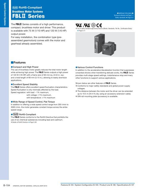
The <strong>FBL</strong> <strong>Series</strong> consists of a high performance,<br />
compact, brushless motor and driver. This product<br />
is available with 75 W (1/10 HP) and 120 W (1/6 HP)<br />
output power.<br />
For easy installation, the combination type (preassembled<br />
gearmotors) comes with the motor and<br />
gearhead already assembled.<br />
●Additional Information●<br />
Technical reference ➜ Page F-1<br />
Safety standards ➜ Page G-2<br />
●List of safety standard approved products (Model, Standards, File No., Certification Body)<br />
➜ Page G-11<br />
■Features<br />
●Compact and High Power<br />
The use of brushless motor greatly reduces the total motor length<br />
while achieving high power. The <strong>FBL</strong> <strong>Series</strong> outputs a high power<br />
of 120 W (1/6 HP) with a frame size of 90 mm sq. (3.54 in. sq.)<br />
and a total length of 80 mm (3.15 in.), allowing to easily downsize<br />
applications.<br />
●Excellent Speed Stability<br />
The <strong>FBL</strong> <strong>Series</strong> offers excellent speed fluctuation characteristics.<br />
Speed fluctuation is only minimally affected by the load.<br />
Speed regulation: with load −1% maximum,<br />
with voltage ±1% maximum,<br />
with temperature ±1% maximum<br />
●Wide Range of Speed Control, Flat Torque<br />
In addition to offering a wide speed control range from 300 r/min to<br />
3000 r/min, the motor generates constant torque across the entire<br />
speed range.<br />
● RoHS-Compliant<br />
The <strong>FBL</strong> <strong>Series</strong> conforms to the RoHS Directive that prohibits the<br />
use of six chemical substances including lead and cadmium.<br />
●Details of RoHS Directive ➜ Page G-38<br />
●Various Control Functions<br />
In addition to the acceleration/deceleration function that suppresses<br />
unwanted shocks when transferring delicate works, the <strong>FBL</strong> <strong>Series</strong><br />
provides multi-stage speed settings, instantaneous stop and many<br />
other functions to support various applications.<br />
Shown below are other features of <strong>FBL</strong> <strong>Series</strong>.<br />
● Conforms to major safety standards and global power supply<br />
voltages.<br />
● The distance between the motor and the driver can be extended<br />
up to 10.5 m (34.4 ft.) (by using an accessory extension cable).<br />
● DIN rail mounting plate (accessory) is available.<br />
B-104 ORIENTAL MOTOR GENERAL CATALOG 2009/2010 Features B-104 / System Configuration B-105 / Product Line B-106 / Specifications B-107
■System Configuration<br />
<strong>FBL</strong> <strong>Series</strong><br />
Combination Type<br />
(<strong>Motor</strong>/Gearhead)<br />
Accessories (Sold separately)<br />
1Extension Cables,<br />
Flexible Extension Cables<br />
(➜ Page B-116)<br />
4Mounting Brackets<br />
(➜ Page A-288)<br />
●Example of System Configuration<br />
(Sold separately)<br />
External Speed<br />
Potentiometer<br />
(Included)<br />
Driver<br />
2<strong>Motor</strong> Speed Indicator<br />
●Not a standard certified product<br />
(➜ Page A-298)<br />
5Flexible Couplings<br />
(➜ Page A-292)<br />
Programmable<br />
Controller<br />
(Not supplied)<br />
AC Power Supply<br />
(Main power supply)<br />
24 VDC<br />
Power Supply ✽<br />
✽Required as a signal when<br />
the driver’s built-in power<br />
supply is not used.<br />
3DIN Rail Mounting Plate<br />
(➜ Page A-301)<br />
No. Product Name Overview Page<br />
1<br />
Extension Cables<br />
Cable for extending the wiring distance between the motor and driver [1 to 10 m (3.3 to 32.8 ft.)].<br />
Flexible Extension Cables Cable offering flexibility, used to extend the wiring distance between the motor and driver [1 to 10 m (3.3 to 32.8 ft.)].<br />
B-116<br />
<strong>Motor</strong> Speed Indicator Indicates motor speed of the speed control motor (SDM496).<br />
DIN Rail Mounting Plate Use this plate when installing the driver to a DIN rail (PADP01).<br />
Mounting Brackets Dedicated mounting bracket for the motor and gearhead.<br />
2<br />
3<br />
4<br />
5<br />
Flexible Couplings<br />
<strong>FBL</strong> <strong>Series</strong><br />
Combination Type - Parallel Shaft<br />
<strong>FBL</strong>575AW-30<br />
Clamp type coupling that connects the motor or gearhead shaft to the driven shaft.<br />
Extension Cable<br />
[1 m (3.3 ft.)]<br />
CC01<strong>FBL</strong><br />
<strong>Motor</strong> Speed<br />
Indicator<br />
SDM496<br />
DIN Rail<br />
Mounting Plate<br />
PADP01<br />
Mounting Bracket<br />
SOL5M8<br />
Flexible Coupling<br />
MCL5518F12<br />
A-298<br />
A-301<br />
A-288<br />
A-292<br />
Brushless <strong>Motor</strong> Systems AC <strong>Motor</strong> Systems<br />
Speed Control Systems Introduction<br />
AC Input<br />
BX<br />
AC Input<br />
BLF<br />
AC Input<br />
BLU<br />
AC Input<br />
<strong>FBL</strong><br />
DC Input<br />
BLH BHF<br />
FE100/<br />
FE200<br />
ES01/<br />
ES02 US Installation<br />
● The system configuration shown above is an example. Other combinations are available.<br />
Characteristics B-109 / Dimensions B-109 / Connection and Operation B-112 / <strong>Motor</strong> and Driver Combinations B-116<br />
B-105
Speed Control Systems<br />
■Product Number Code<br />
<strong>FBL</strong> 5 75 A W - 5<br />
1 2 3 4 5 6<br />
1 <strong>Series</strong> <strong>FBL</strong>: <strong>FBL</strong> <strong>Series</strong><br />
2 <strong>Motor</strong> Frame Size 5: 90 mm (3.54 in.)<br />
3 Output Power (W) (Example) 75: 75 W (1/10 HP)<br />
4<br />
5<br />
6<br />
Power Supply Voltage A: Single-Phase 100-115 VAC C: Single-Phase 200-230 VAC<br />
S: Three-Phase 200-230 VAC<br />
W: Comforms to Safety Standards<br />
Gear Ratio/Shaft Type Number: Gear ratio for combination types: 8 types from 5 to 200<br />
A: Round Shaft Type<br />
GFB: GFB Type Pinion Shaft<br />
■Product Line<br />
Combination Type The combination type comes with the motor and its dedicated gearhead pre-assembled, which simplifies installation in<br />
equipment. <strong>Motor</strong>s and gearheads are also available separately to facilitate changes or repairs.<br />
●Combination Type<br />
Output Power Power Supply Voltage Model Gear Ratio<br />
75 W<br />
(1/10 HP)<br />
120 W<br />
(1/6 HP)<br />
Single-Phase<br />
100-115 VAC<br />
Single-Phase<br />
200-230 VAC<br />
Three-Phase<br />
200-230 VAC<br />
Single-Phase<br />
100-115 VAC<br />
Single-Phase<br />
200-230 VAC<br />
Three-Phase<br />
200-230 VAC<br />
<strong>FBL</strong>575AW-□<br />
<strong>FBL</strong>575CW-□<br />
<strong>FBL</strong>575SW-□<br />
<strong>FBL</strong>5120AW-□<br />
<strong>FBL</strong>5120CW-□<br />
<strong>FBL</strong>5120SW-□<br />
●Enter the gear ratio in the box ( □) within the model name.<br />
The following items are included in each product.<br />
<strong>Motor</strong>, Driver, Gearhead, External Speed Potentiometer (with signal wire),<br />
Mounting Brackets for Driver (with screws), Mounting Screws, Parallel<br />
Key, Operating Manual<br />
5, 10, 15, 20, 30,<br />
50, 100, 200<br />
5, 10, 15, 20, 30,<br />
50, 100, 200<br />
5, 10, 15, 20, 30,<br />
50, 100, 200<br />
5, 10, 15, 20, 30,<br />
50, 100, 200<br />
5, 10, 15, 20, 30,<br />
50, 100, 200<br />
5, 10, 15, 20, 30,<br />
50, 100, 200<br />
●Round Shaft Type<br />
Output Power Power Supply Voltage Model<br />
75 W<br />
(1/10 HP)<br />
120 W<br />
(1/6 HP)<br />
Single-Phase<br />
100-115 VAC<br />
Single-Phase<br />
200-230 VAC<br />
Three-Phase<br />
200-230 VAC<br />
Single-Phase<br />
100-115 VAC<br />
Single-Phase<br />
200-230 VAC<br />
Three-Phase<br />
200-230 VAC<br />
<strong>FBL</strong>575AW-A<br />
<strong>FBL</strong>575CW-A<br />
<strong>FBL</strong>575SW-A<br />
<strong>FBL</strong>5120AW-A<br />
<strong>FBL</strong>5120CW-A<br />
<strong>FBL</strong>5120SW-A<br />
The following items are included in each product.<br />
<strong>Motor</strong>, Driver, External Speed Potentiometer (with signal wire), Mounting<br />
Brackets for Driver (with screws), Operating Manual<br />
●Pinion Shaft Type<br />
Output Power Power Supply Voltage Model<br />
75 W<br />
(1/10 HP)<br />
120 W<br />
(1/6 HP)<br />
Single-Phase<br />
100-115 VAC<br />
Single-Phase<br />
200-230 VAC<br />
Three-Phase<br />
200-230 VAC<br />
Single-Phase<br />
100-115 VAC<br />
Single-Phase<br />
200-230 VAC<br />
Three-Phase<br />
200-230 VAC<br />
<strong>FBL</strong>575AW-GFB<br />
<strong>FBL</strong>575CW-GFB<br />
<strong>FBL</strong>575SW-GFB<br />
<strong>FBL</strong>5120AW-GFB<br />
<strong>FBL</strong>5120CW-GFB<br />
<strong>FBL</strong>5120SW-GFB<br />
●Gearhead<br />
Output Power of Applicable<br />
<strong>Motor</strong> (Pinion shaft type)<br />
75 W (1/10 HP)<br />
120 W (1/6 HP)<br />
Gearhead Model<br />
GFB5G□<br />
Gear Ratio<br />
5, 10, 15, 20, 30,<br />
50, 100, 200<br />
●Enter the gear ratio in the box ( □) within the model name.<br />
The following items are included in each product.<br />
Gearhead, Mounting Screws for Connecting <strong>Motor</strong> and Gearhead,<br />
Mounting Screws, Parallel Key, Operating Manual<br />
The following items are included in each product.<br />
<strong>Motor</strong>, Driver, External Speed Potentiometer (with signal wire), Mounting<br />
Brackets for Driver (with screws), Operating Manual<br />
B-106 ORIENTAL MOTOR GENERAL CATALOG 2009/2010 Features B-104 / System Configuration B-105 / Product Line B-106 / Specifications B-107
■Specifications<br />
● 75 W (1/10 HP), 120 W (1/6 HP)<br />
Combination Type – Parallel Shaft Gearhead <strong>FBL</strong>575AW-□ <strong>FBL</strong>575CW-□ <strong>FBL</strong>575SW-□ <strong>FBL</strong>5120AW-□ <strong>FBL</strong>5120CW-□ <strong>FBL</strong>5120SW-□<br />
Model<br />
Round Shaft Type <strong>FBL</strong>575AW-A <strong>FBL</strong>575CW-A <strong>FBL</strong>575SW-A <strong>FBL</strong>5120AW-A <strong>FBL</strong>5120CW-A <strong>FBL</strong>5120SW-A<br />
Rated Output Power (Continuous) W (HP) 75 (1/10) 120 (1/6)<br />
Rated Voltage<br />
VAC<br />
Single-Phase<br />
100-115<br />
Single-Phase<br />
200-230<br />
Three-Phase<br />
200-230<br />
Single-Phase<br />
100-115<br />
Single-Phase<br />
200-230<br />
Power Source<br />
Permissible Voltage Range ±10%<br />
Rated Frequency Hz 50/60<br />
Rated Input Current A 2.3 1.4 0.75 3.0 1.8 1.0<br />
Maximum Input Current A 2.6 2.0 1.2 3.8 2.7 1.6<br />
Rated Torque N·m (oz-in) 0.25 (35) 0.4 (56)<br />
Starting Torque N·m (oz-in) 0.32 (45) 0.5 (71)<br />
Rated Speed r/min 3000<br />
Speed Control Range r/min 300∼3000<br />
Round Shaft Type<br />
Permissible Load Inertia J<br />
×10 −4 kg·m 2 (oz-in 2 ) 3.75 (21) 5.62 (31)<br />
Rotor Inertia J ×10 −4 kg·m 2 (oz-in 2 ) 0.968 (5.3) 1.961 (10.7)<br />
Load<br />
−1% max. (0∼Rated torque, at rated speed, at rated voltage, at normal ambient temperature)<br />
Speed Regulation Voltage<br />
±1% max. (Rated voltage ±10%, at rated speed, with no load, at normal ambient temperature)<br />
Temperature<br />
±1% max. [0∼+50˚C (+32∼+122˚F), at rated speed, with no load, at rated voltage]<br />
✽ Single-phase motors are certified by DEMKO.<br />
●Enter the gear ratio in the box ( □) within the model name.<br />
●The values for each specification apply to the motor only.<br />
■Common Specifications<br />
Item<br />
Speed Setting Methods<br />
Input Signals<br />
Output Signals<br />
Protective Functions ✽<br />
Time Rating<br />
Specifications<br />
Select one of the following methods:<br />
· Set using the internal speed potentiometer<br />
· Set using an external speed potentiometer: PAVR-20KZ (20 kΩ, 1/4 W)<br />
· Set using external DC voltage: 0∼5 VDC<br />
Photocoupler input<br />
Input resistance 4.8 kΩ, 24 VDC±10%<br />
Common to EXT. VR., CW, CCW, SLOW DOWN<br />
Open-collector output External use condition 26.4 VDC, 10 mA max.<br />
Common to SPEED OUT, ALARM OUT<br />
When the following are activated, the motor will coast to a stop and the ALARM output will be OFF.<br />
· Overload protection: Activated when the motor load exceeds rated torque for a minimum of 5 seconds.<br />
· Overheat protection: Activated when the temperature of the heat sink inside driver exceeds approximately 90°C (194°F).<br />
· Overvoltage protection: Activated when a gravitational operation is performed or a load exceeding the permissible load inertia is driven.<br />
· Undervoltage protection: Activated when the power supply voltage applied to the driver dropped below the specified voltage (−10%).<br />
· Missing phase protection: Activated when the sensor wire inside the motor cable is disconnected during motor operation.<br />
Continuous<br />
✽<br />
Three-Phase<br />
200-230<br />
✽ With the <strong>FBL</strong> <strong>Series</strong>, the motor speed cannot be controlled in a gravitational operation or other application where the motor shaft is turned by the load. When a load exceeding the permissible<br />
load inertia is driven or a gravitational operation is performed, the overvoltage protective function will be activated and the motor will coast to a stop.<br />
■General Specifications<br />
Insulation Resistance<br />
Item <strong>Motor</strong> Driver<br />
100 MΩ or more when 500 VDC megger is applied between the<br />
windings and the case after continuous operation under normal<br />
ambient temperature and humidity.<br />
100 MΩ or more when 500 VDC megger is applied between the power supply<br />
terminal and the protective earth terminal, and between the power supply input<br />
terminal and the I/O terminal after continuous operation under normal ambient<br />
temperature and humidity.<br />
Brushless <strong>Motor</strong> Systems AC <strong>Motor</strong> Systems<br />
Speed Control Systems Introduction<br />
AC Input<br />
BX<br />
AC Input<br />
BLF<br />
AC Input<br />
BLU<br />
AC Input<br />
<strong>FBL</strong><br />
DC Input<br />
BLH BHF<br />
FE100/<br />
FE200<br />
ES01/<br />
ES02 US Installation<br />
Dielectric Strength<br />
Operating<br />
Environment<br />
Ambient Temperature<br />
Ambient Humidity<br />
Atmosphere<br />
Sufficient to withstand 1.5 kVAC at 50 Hz applied between the<br />
windings and the case for 1 minute after continuous operation<br />
under normal ambient temperature and humidity.<br />
Sufficient to withstand 1.8 kVAC at 50 Hz applied between the power supply<br />
terminal and the protective earth terminal for 1 minute, and 3 kVAC at 50 Hz<br />
applied between the power supply terminal and the I/O terminal for 1 minute after<br />
continuous operation under normal ambient temperature and humidity.<br />
0∼+50˚C (+32∼+122˚F) (non-freezing)<br />
85% or less (non-condensing)<br />
No corrosive gases or dust<br />
Insulation Class UL, CSA: Class A [105˚C (221˚F)] EN: Class E [120˚C (248˚F)] −<br />
Degree of Protection IP40 IP10<br />
Note:<br />
●Do not measure insulation resistance or perform the dielectric strength test while the motor and driver are connected.<br />
Characteristics B-109 / Dimensions B-109 / Connection and Operation B-112 / <strong>Motor</strong> and Driver Combinations B-116<br />
B-107
Speed Control Systems<br />
■Gearmotor – Torque Table of Combination Type<br />
Model<br />
<strong>FBL</strong>575AW-□<br />
<strong>FBL</strong>575CW-□<br />
<strong>FBL</strong>575SW-□<br />
<strong>FBL</strong>5120AW-□<br />
<strong>FBL</strong>5120CW-□<br />
<strong>FBL</strong>5120SW-□<br />
Unit = N·m (lb-in)<br />
Gear Ratio 5 10 15 20 30 50 100 200<br />
Speed Range r/min 60∼600 30∼300 20∼200 15∼150 10∼100 6∼60 3∼30 1.5∼15<br />
1.1<br />
(9.7)<br />
1.8<br />
(15.9)<br />
2.3<br />
(20)<br />
3.6<br />
(31)<br />
●Enter the gear ratio in the box ( □) within the model name.<br />
● A colored background ( ) indicates gear shaft rotation in the same direction as the motor shaft, while the others rotate in the opposite direction.<br />
3.4<br />
(30)<br />
5.4<br />
(47)<br />
4.5<br />
(39)<br />
7.2<br />
(63)<br />
6.5<br />
(57)<br />
10.3<br />
(91)<br />
10.8<br />
(95)<br />
17.2<br />
(152)<br />
21.5<br />
(190)<br />
30<br />
(260)<br />
30<br />
(260)<br />
30<br />
(260)<br />
■Permissible Overhung Load and Permissible Thrust Load<br />
●Combination Type<br />
Model<br />
<strong>FBL</strong>575AW-□<br />
<strong>FBL</strong>575CW-□<br />
<strong>FBL</strong>575SW-□<br />
<strong>FBL</strong>5120AW-□<br />
<strong>FBL</strong>5120CW-□<br />
<strong>FBL</strong>5120SW-□<br />
Gear Ratio<br />
●Enter the gear ratio in the box ( □) within the model name.<br />
Permissible Overhung Load<br />
Permissible Thrust Load<br />
10 mm (0.39 in.) from shaft end 20 mm (0.79 in.) from shaft end<br />
N lb. N lb. N lb.<br />
5 300 67 400 90<br />
10, 15, 20 400 90 500 112<br />
30, 50, 100, 200 500 112 650 146<br />
150 33<br />
●Round Shaft Type<br />
Model<br />
<strong>FBL</strong>575AW-A<br />
<strong>FBL</strong>575CW-A<br />
<strong>FBL</strong>575SW-A<br />
<strong>FBL</strong>5120AW-A<br />
<strong>FBL</strong>5120CW-A<br />
<strong>FBL</strong>5120SW-A<br />
Permissible Overhung Load<br />
10 mm (0.39 in.) from shaft end 20 mm (0.79 in.) from shaft end<br />
N lb. N lb.<br />
130 29 150 33<br />
160 36 170 38<br />
Permissible Thrust Load<br />
The permissible thrust load<br />
shall be no greater than half<br />
the motor mass.<br />
■Permissible Load Inertia J of Combination Type<br />
Unit = ×10 −4 kg·m 2 (oz-in 2 )<br />
Model Gear Ratio 5 10 15 20 30 50 100 200<br />
<strong>FBL</strong>575AW-□<br />
<strong>FBL</strong>575CW-□<br />
<strong>FBL</strong>575SW-□<br />
<strong>FBL</strong>5120AW-□<br />
<strong>FBL</strong>5120CW-□<br />
<strong>FBL</strong>5120SW-□<br />
25<br />
(137)<br />
●Enter the gear ratio in the box ( □) within the model name.<br />
100<br />
(550)<br />
225<br />
(1230)<br />
400<br />
(2200)<br />
900<br />
(4900)<br />
2500<br />
(13700)<br />
2500<br />
(13700)<br />
2500<br />
(13700)<br />
B-108 ORIENTAL MOTOR GENERAL CATALOG 2009/2010 Features B-104 / System Configuration B-105 / Product Line B-106 / Specifications B-107
■Speed – Torque Characteristics<br />
Continuous Duty Region: Continuous operation is possible in this region.<br />
Limited Duty Region: This region is used primarily when accelerating. When a load that exceeds the rated torque is applied continuously for<br />
approximately five seconds, overload protection is activated and the motor coasts to a stop.<br />
<strong>FBL</strong>575AW-□/<strong>FBL</strong>575CW-□/<strong>FBL</strong>575SW-□<br />
<strong>FBL</strong>575AW-A/<strong>FBL</strong>575CW-A/<strong>FBL</strong>575SW-A<br />
Torque<br />
[oz-in]<br />
50<br />
40<br />
30<br />
20<br />
10<br />
0<br />
0[N•m]<br />
0.32<br />
0.3<br />
0.25<br />
0.2<br />
0.1<br />
0 300 1000 2000 3000<br />
Speed [r/min]<br />
■Dimensions<br />
Starting Torque<br />
Limited Duty Region<br />
Continuous Duty Region<br />
●The characteristics shown above are applicable for the motors only.<br />
●Enter the gear ratio in the box ( □) within the model name.<br />
Unit = mm (in.)<br />
Rated Torque<br />
● Mounting screws are included with the combination type. Dimensions for mounting screws ➜ Page B-222<br />
●75 W (1/10 HP)<br />
◇<strong>Motor</strong>/Gearhead<br />
<strong>FBL</strong>5120AW-□/<strong>FBL</strong>5120CW-□/<strong>FBL</strong>5120SW-□<br />
<strong>FBL</strong>5120AW-A/<strong>FBL</strong>5120CW-A/<strong>FBL</strong>5120SW-A<br />
Torque<br />
70<br />
60<br />
50<br />
40<br />
30<br />
20<br />
10<br />
0<br />
Starting Torque<br />
Limited Duty Region<br />
Continuous Duty Region<br />
0 300 1000 2000 3000<br />
Speed [r/min]<br />
Model <strong>Motor</strong> Model Gearhead Model Gear Ratio L DXF<br />
<strong>FBL</strong>575AW-□<br />
<strong>FBL</strong>575CW-□ <strong>FBL</strong>M575W-GFB<br />
<strong>FBL</strong>575SW-□<br />
Mass: 3.0 kg (6.6 lb.) (Including gearhead)<br />
14 (0.55)<br />
57 (2.24)<br />
10 (0.39)<br />
33<br />
(1.30)<br />
L 42 (1.65)<br />
5 (0.20) 25<br />
(0.98)<br />
A<br />
A<br />
0<br />
ϕ18−0.018<br />
0<br />
(ϕ0.7087−0.0007)<br />
18 (0.71)<br />
ϕ40 (ϕ1.57)<br />
□90 (□3.54)<br />
GFB5G□<br />
104±0.5<br />
Housing: 5557-12R (MOLEX)<br />
<strong>Motor</strong> Cable ϕ9 (ϕ0.35), 500mm (20 in.) Length<br />
(4.09±0.02)<br />
[oz-in]<br />
0[N•m]<br />
0.5<br />
0.4<br />
0.3<br />
0.2<br />
0.1<br />
5∼20 45 (1.77) A204A<br />
30∼100 58 (2.28) A204B<br />
200 64 (2.52) A204C<br />
4×ϕ8.5 (ϕ0.335) Thru<br />
27<br />
(1.06)<br />
Rated Torque<br />
Brushless <strong>Motor</strong> Systems AC <strong>Motor</strong> Systems<br />
Speed Control Systems Introduction<br />
AC Input<br />
BX<br />
AC Input<br />
BLF<br />
AC Input<br />
BLU<br />
AC Input<br />
<strong>FBL</strong><br />
DC Input<br />
BLH BHF<br />
FE100/<br />
FE200<br />
ES01/<br />
ES02 US Installation<br />
◇Key and Key Slot<br />
(The key is included with the gearhead)<br />
25±0.2<br />
(0.984±0.008)<br />
0 0<br />
( )<br />
6−0.03 0.2362−0.0012 0<br />
6−0.03<br />
+0.040<br />
6 0<br />
+0.0016<br />
0<br />
( 0.2362−0.0012 ) ( 0.2362 0 )<br />
+0.1<br />
3.5 0 (<br />
+0.004<br />
0.138 0 )<br />
A−A<br />
●Enter the gear ratio in the box ( □) within the model name.<br />
Characteristics B-109 / Dimensions B-109 / Connection and Operation B-112 / <strong>Motor</strong> and Driver Combinations B-116<br />
B-109
Speed Control Systems<br />
◇Round Shaft Type<br />
<strong>FBL</strong>575AW-A, <strong>FBL</strong>575CW-A, <strong>FBL</strong>575SW-A<br />
<strong>Motor</strong>: <strong>FBL</strong>M575W-A<br />
Mass: 1.5kg (3.3 lb.)<br />
A206<br />
57 (2.24) 37 (1.46)<br />
10 (0.39) 2 (0.08)<br />
0<br />
ϕ10−0.015<br />
0<br />
(ϕ0.3937−0.0006)<br />
4×ϕ8.5 (ϕ0.335) Thru<br />
14 (0.55)<br />
30<br />
(1.18)<br />
9 (0.35)<br />
0<br />
ϕ83−0.035<br />
0<br />
(ϕ3.2677−0.0014)<br />
□90 (□3.54)<br />
104±0.5<br />
(4.09±0.02)<br />
33<br />
(1.30)<br />
Housing: 5557-12R (MOLEX)<br />
<strong>Motor</strong> Cable ϕ9 (ϕ0.35), 500mm (20 in.) Length<br />
27<br />
(1.06)<br />
●120 W (1/6 HP)<br />
◇<strong>Motor</strong>/Gearhead<br />
Model <strong>Motor</strong> Model Gearhead Model Gear Ratio L DXF<br />
<strong>FBL</strong>5120AW-□<br />
<strong>FBL</strong>5120CW-□ <strong>FBL</strong>M5120W-GFB<br />
<strong>FBL</strong>5120SW-□<br />
Mass: 4.0 kg (8.8 lb.) (Including gearhead)<br />
GFB5G□<br />
5∼20 45 (1.77) A205A<br />
30∼100 58 (2.28) A205B<br />
200 64 (2.52) A205C<br />
80 (3.15) L<br />
10 (0.39) 5 (0.20)<br />
42 (1.65)<br />
25<br />
(0.98)<br />
0<br />
ϕ18−0.018<br />
0<br />
(ϕ0.7087−0.0007)<br />
4×ϕ8.5 (ϕ0.335) Thru<br />
A<br />
14 (0.55)<br />
A<br />
18 (0.71)<br />
ϕ40 (ϕ1.57)<br />
□90 (□3.54)<br />
104±0.5<br />
(4.09±0.02)<br />
33<br />
(1.30)<br />
Housing: 5557-12R (MOLEX)<br />
<strong>Motor</strong> Cable ϕ9 (ϕ0.35), 500mm (20 in.) Length<br />
27<br />
(1.06)<br />
◇Key and Key Slot<br />
(The key is included with the gearhead)<br />
25±0.2<br />
(0.984±0.008)<br />
0 0<br />
( )<br />
6−0.03 0.2362−0.0012 0<br />
6−0.03<br />
+0.040<br />
6 0<br />
+0.0016<br />
0<br />
( 0.2362−0.0012 ) ( 0.2362 0 )<br />
+0.1<br />
3.5 0 (0.138<br />
+0.004<br />
0 )<br />
A−A<br />
●Enter the gear ratio in the box ( □) within the model name.<br />
B-110 ORIENTAL MOTOR GENERAL CATALOG 2009/2010 Features B-104 / System Configuration B-105 / Product Line B-106 / Specifications B-107
◇Round Shaft Type<br />
<strong>FBL</strong>5120AW-A, <strong>FBL</strong>5120CW-A, <strong>FBL</strong>5120SW-A<br />
<strong>Motor</strong>: <strong>FBL</strong>M5120W-A<br />
Mass: 2.5kg (5.5 lb.)<br />
A207<br />
14 (0.55)<br />
33<br />
(1.30)<br />
80 (3.15) 37 (1.46)<br />
10 (0.39) 2 (0.08)<br />
30<br />
(1.18)<br />
0<br />
11<br />
(0.43)<br />
ϕ12−0.018<br />
0<br />
(ϕ0.4724−0.0007)<br />
0<br />
ϕ83−0.035<br />
0<br />
(ϕ3.2677−0.0014)<br />
□90 (□3.54)<br />
104±0.5<br />
(4.09±0.02)<br />
Housing: 5557-12R (MOLEX)<br />
<strong>Motor</strong> Cable ϕ9 (ϕ0.35), 500mm (20 in.) Length<br />
◇Driver (Common to all models)<br />
<strong>FBL</strong>D75AW, <strong>FBL</strong>D75CW, <strong>FBL</strong>D75SW,<br />
<strong>FBL</strong>D120AW, <strong>FBL</strong>D120CW, <strong>FBL</strong>D120SW<br />
Mass: 0.8kg (1.76 lb.)<br />
A283<br />
7×M3<br />
89 (3.50)<br />
25<br />
(0.98)<br />
9<br />
(0.35)<br />
25<br />
(0.98)<br />
23<br />
(0.91)<br />
9<br />
(0.35)<br />
134 (5.28)<br />
10<br />
(0.39)<br />
10<br />
(0.39)<br />
10 (0.39)<br />
59 (2.32) 25<br />
(0.98)<br />
◇Driver Base Mounting Bracket Tab<br />
(2 pieces included)<br />
45<br />
20 (0.79)<br />
10 (0.39)<br />
(1.77)<br />
25<br />
(0.98)<br />
2×ϕ3.5 (ϕ0.138)<br />
Countersink<br />
20 (0.79)<br />
10 (0.39)<br />
4×ϕ8.5 (ϕ0.335) Thru<br />
27<br />
(1.06)<br />
120 (4.72) 17 (0.67) max.<br />
4.5 (0.18)<br />
25<br />
(0.98)<br />
45<br />
(1.77)<br />
2×M3<br />
◇Driver Back Mounting Tab (Included)<br />
200 (7.87)<br />
31<br />
134 (5.28)<br />
10 (1.22)<br />
(0.39)<br />
20<br />
(0.79)<br />
7.62 (0.30) Pitch<br />
6.32 (0.25)<br />
Protective Earth Terminal M4<br />
3<br />
(0.12)<br />
20<br />
(0.79)<br />
10<br />
(0.39)<br />
45 (1.77)<br />
4×M3<br />
6.32 (0.25)<br />
7.62 (0.30) Pitch<br />
12×M3<br />
150 (5.91)<br />
◇External Speed Potentiometer (Included)<br />
ϕ20 (ϕ0.79)<br />
ϕ2.8 (ϕ0.11)<br />
30 (1.18) min.<br />
9.5<br />
(0.37)<br />
15<br />
(0.59)<br />
M4×6 (0.24) Deep<br />
Screw<br />
ϕ3±0.2 ϕ9.5±0.2<br />
(ϕ0.118±0.008) (ϕ0.374±0.008)<br />
Potentiometer<br />
Knob<br />
Insulated Sheet Dial Plate<br />
Insulated Sheet<br />
□40 (□1.57) t=0.5 (0.02) □40 (□1.57) t=0.5 (0.02)<br />
Brushless <strong>Motor</strong> Systems AC <strong>Motor</strong> Systems<br />
Speed Control Systems Introduction<br />
AC Input<br />
BX<br />
AC Input<br />
BLF<br />
AC Input<br />
BLU<br />
AC Input<br />
<strong>FBL</strong><br />
DC Input<br />
BLH BHF<br />
FE100/<br />
FE200<br />
ES01/<br />
ES02 US Installation<br />
45 (1.77)<br />
25<br />
(0.98)<br />
ϕ20<br />
(ϕ0.79)<br />
3<br />
(0.12)<br />
40 (1.57)<br />
12.5<br />
(0.49)<br />
40 (1.57)<br />
7.5 (0.30)<br />
10<br />
(0.39)<br />
4×4.5<br />
(0.18)<br />
Recommended thickness of a mounting plate is a maximum 4.5 mm (0.18 in.).<br />
4×ϕ3.5 (ϕ0.138) Countersink<br />
Characteristics B-109 / Dimensions B-109 / Connection and Operation B-112 / <strong>Motor</strong> and Driver Combinations B-116<br />
B-111
Speed Control Systems<br />
■Connection and Operation<br />
●Names and Functions of Driver Parts<br />
Internal Potentiometer<br />
Display<br />
Function<br />
SPEED Internal Speed Potentiometer<br />
S.S. Acceleration Time Potentiometer ✽<br />
S.D. Deceleration Time Potentiometer ✽<br />
✽ Acceleration/Deceleration Time Setting:<br />
0.5∼15 sec. (3000 r/min)<br />
For <strong>Motor</strong> Connector<br />
Display<br />
POWER<br />
ALARM<br />
Function<br />
Power<br />
Indicator<br />
LED Display<br />
Lighting Condition<br />
Lights when the power is ON.<br />
●When the motor load exceeds rated torque<br />
for a minimum of 5 seconds.<br />
●When the temperature of the heat sink inside<br />
driver exceeds approximately 90°C (194°F).<br />
●When a load exceeding the permissible load<br />
Alarm<br />
Indicator inertia is driven.<br />
●When a gravitational operation is performed.<br />
●When the power supply voltage applied to the<br />
driver dropped below the specified voltage<br />
(−10%).<br />
●When the sensor wire inside the motor cable<br />
is disconnected.<br />
Power Supply Terminal Block<br />
I/O Power Supply Switch<br />
Display<br />
Function<br />
When controlling from a programmable controller or<br />
EXT.<br />
other external power supply. (Factory setting)<br />
When controlling with a relay or switch.<br />
INT.<br />
(Driver built-in power supply)<br />
● When the switch is set to EXT., the input circuit is insulated by the<br />
photocoupler. However when the switch is set to INT., the input<br />
circuit is not insulated, so the system will not work, even if an input<br />
signal is input, unless GND is connected to a controller.<br />
Input/Output Signal Terminal Block<br />
Display Signal Name Function<br />
INPUT<br />
COM<br />
EXT.VR.<br />
CW<br />
CCW<br />
Power Supply for<br />
Input Signals<br />
Speed Setting<br />
Selection Input<br />
CW Rotation Input<br />
CCW Rotation Input<br />
SLOW DOWN Deceleration Input<br />
N.C.<br />
—<br />
H<br />
M Speed Setting Input<br />
L<br />
GND Ground<br />
SPEED OUT<br />
ALARM OUT<br />
Speed Output<br />
(Open-Collector Output)<br />
Alarm Output<br />
(Open-Collector Output)<br />
External power supply +24 VDC<br />
A connection is not necessary<br />
when using the driver's built-in<br />
power supply.<br />
Input signal for selecting internal<br />
or external speed potentiometer.<br />
Input signal for selecting CW<br />
rotation/stop.<br />
Input signal for selecting CCW<br />
rotation/stop.<br />
Input terminal for decelerating<br />
the motor to a stop.<br />
Not used.<br />
Used when controlling the speed<br />
by an external potentiometer or<br />
DC voltage.<br />
Common ground terminal for<br />
input/output signals.<br />
Used when monitoring the<br />
motor speed; 12 pulses are<br />
output for each motor rotation.<br />
This signal is output when a<br />
protective function is activated.<br />
The ALARM LED lights and the<br />
motor coasts to a stop. To reset,<br />
turn off the power for 30 seconds,<br />
then turn the power on again.<br />
B-112 ORIENTAL MOTOR GENERAL CATALOG 2009/2010 Features B-104 / System Configuration B-105 / Product Line B-106 / Specifications B-107
MOTOR<br />
MOTOR<br />
●Connection Diagrams<br />
◇ <strong>FBL</strong>575AW, <strong>FBL</strong>575CW,<br />
<strong>FBL</strong>5120AW, <strong>FBL</strong>5120CW<br />
Driver<br />
<strong>Motor</strong> cable w/connector<br />
0.5m (20 in.)<br />
●<strong>Motor</strong> cable should be no more than 10.5 m (34.4 ft.) in length. The motor comes with 0.5m (20 in.) long connector-equipped cable which can be extended by using an accessory extension cable<br />
(sold separately).<br />
There are six different length extension cables. Also there are flexible extension cables.<br />
[Length: 1 m (3.3 ft.), 2 m (6.6 ft.), 3 m (9.8 ft.), 5 m (16.8 ft.), 7 m (23.0 ft.), 10 m (32.8 ft.)]<br />
Extension cables, flexible extension cables ➜ Page B-116<br />
●Signal wires and motor wires should be kept away from equipment, power cables and other sources of magnetic noise.<br />
◇Applicable Crimp Terminals<br />
●Round Terminal with Insulation (M3)<br />
6.2 mm (0.24 in.) max.<br />
ϕ3.2 mm (0.13 in.) min.<br />
●Timing Chart<br />
Input Signal<br />
CW<br />
CCW<br />
SLOW DOWN<br />
EXT.VR.<br />
<strong>Motor</strong><br />
<strong>Motor</strong><br />
Power Supply Connection<br />
Single-phase<br />
100-115 VAC±10%<br />
50/60 Hz<br />
Single-phase<br />
200-230 VAC±10%<br />
50/60 Hz<br />
9 mm<br />
(0.35 in.) min.<br />
Signal<br />
Input<br />
ON<br />
OFF<br />
ON<br />
OFF<br />
ON<br />
OFF<br />
ON<br />
OFF<br />
SPEED<br />
S.S.<br />
S.D.<br />
L<br />
N<br />
N.C<br />
FG<br />
Protective Earth Terminal (PE)<br />
Cross sectional area: AWG18 (0.75 mm 2 min.)<br />
Run/Speed-<br />
Select/Stop<br />
CW<br />
POWER<br />
ALARM<br />
EXT.-INT.<br />
INPUT<br />
COM 1<br />
EXT.VR. 2<br />
CW 3<br />
CCW 4<br />
SLOW 5<br />
DOWN<br />
N.C. 6<br />
H 7<br />
M 8<br />
L 9<br />
GND 10<br />
SPEED<br />
11<br />
OUT<br />
ALARM 12<br />
OUT<br />
Run/<br />
Instantaneous<br />
stop<br />
CW<br />
CW<br />
24 VDC±10% 0.1A min.<br />
Connection is not necessary<br />
when using the driver's built-in<br />
power supply.<br />
Speed<br />
Potentiometer ON: External Potentiometer<br />
Selection Input<br />
CW Input ON: CW Rotation<br />
( OFF: Stop )<br />
CCW Input ON: CCW Rotation<br />
( OFF: Stop )<br />
Slow Down Input ON: Deceleration<br />
3<br />
2<br />
1<br />
Speed Potentiometer<br />
20 kΩ 1/4 W<br />
(included)<br />
Ground<br />
Speed Output<br />
Alarm Output<br />
Rotation Direction<br />
Switching/<br />
Instantaneous<br />
Bi-Directional Operation<br />
CCW<br />
CW<br />
( OFF: Internal Potentiometer )<br />
( OFF: Release )<br />
●U-Shape Terminal with Insulation (M3)<br />
9mm (0.35 in.) min.<br />
Acceleration/<br />
Deceleration Time Setting<br />
Instantaneous Stop<br />
during Deceleration<br />
CW<br />
6.2mm (0.24 in.) max.<br />
ϕ3.2mm (0.13 in.) min.<br />
CW<br />
◇ <strong>FBL</strong>575SW, <strong>FBL</strong>5120SW<br />
<strong>Motor</strong><br />
<strong>Motor</strong> cable w/connector<br />
0.5m (20 in.)<br />
Power Supply Connection<br />
Three-phase<br />
200-230 VAC±10%<br />
50/60 Hz<br />
SPEED<br />
S.S.<br />
S.D.<br />
L1<br />
L2<br />
L3<br />
FG<br />
Driver<br />
Protective Earth Terminal (PE)<br />
Cross sectional area: AWG18 (0.75 mm 2 min.)<br />
POWER<br />
ALARM<br />
EXT.-INT.<br />
INPUT<br />
COM 1<br />
EXT.VR. 2<br />
CW 3<br />
CCW 4<br />
SLOW 5<br />
DOWN<br />
N.C. 6<br />
H 7<br />
M 8<br />
L 9<br />
GND 10<br />
SPEED<br />
11<br />
OUT<br />
ALARM 12<br />
OUT<br />
24 VDC±10% 0.1A min.<br />
Connection is not necessary<br />
when using the driver's built-in<br />
power supply.<br />
Speed<br />
Potentiometer ON: External Potentiometer<br />
Selection Input<br />
CW Input ON: CW Rotation<br />
( OFF: Stop )<br />
CCW Input ON: CCW Rotation<br />
( OFF: Stop<br />
)<br />
Slow Down Input ON: Deceleration<br />
● The CW input signal, CCW input signal and SLOW DOWN input<br />
signal can be used to control all motor operations, such as run,<br />
stop, direction switching, deceleration stop and instantaneous<br />
stop.<br />
● Switching the CW input signal ON will cause the motor to turn<br />
clockwise as viewed from the motor shaft, while switching<br />
the CCW input signal ON will cause the motor to turn<br />
counterclockwise. Switching each input signal OFF will stop the<br />
motor. If both the CW and CCW input signal are turned ON at the<br />
same time, the motor will turn clockwise. The motor will start at<br />
the rise time corresponding to the time set on the acceleration<br />
time potentiometer.<br />
● Switching the SLOW DOWN input signal ON will cause the<br />
motor decelerates and the motor stops at the time set on the<br />
deceleration time potentiometer. Switching the SLOW DOWN<br />
input signal OFF will cause the motor to stop instantaneously.<br />
● Switching the EXT.VR. input signal ON, the external speed<br />
potentiometer (external DC voltage) can be used to set speed,<br />
while internal speed potentiometer can be selected by switching<br />
the EXT.VR. input signal OFF.<br />
3<br />
2<br />
1<br />
Speed Potentiometer<br />
20 kΩ 1/4 W<br />
(included)<br />
Ground<br />
Speed Output<br />
Alarm Output<br />
( OFF: Internal Potentiometer )<br />
( OFF: Release )<br />
Notes:<br />
●Pay attention to the temperature rise of the motor when used in applications requiring short cycles of start/stop (instantaneous stop) operation and bi-directional operation.<br />
●Operate the motor so that the temperature of the motor case remains below 90˚C (194˚F) and the temperature of the driver remains below 80˚C (176˚F). If the temperature of the heat sink in the driver<br />
exceeds 90˚C (194˚F), the overheat protection activates and stops the motor.<br />
●Cannot be used while the gravitational operation or other application where the motor shaft is turned by the load. To prevent damage to the driver during gravitational operations, if the primary voltage<br />
of the driver’s inverter exceeds the permissible value, the protective circuit will be activated.<br />
Brushless <strong>Motor</strong> Systems AC <strong>Motor</strong> Systems<br />
Speed Control Systems Introduction<br />
AC Input<br />
BX<br />
AC Input<br />
BLF<br />
AC Input<br />
BLU<br />
AC Input<br />
<strong>FBL</strong><br />
DC Input<br />
BLH BHF<br />
FE100/<br />
FE200<br />
ES01/<br />
ES02 US Installation<br />
Characteristics B-109 / Dimensions B-109 / Connection and Operation B-112 / <strong>Motor</strong> and Driver Combinations B-116<br />
B-113
Speed Control Systems<br />
●Input/Output Signal Circuit<br />
◇Input Circuit<br />
Common to EXT.VR., CW, CCW, SLOW DOWN<br />
INPUT COM<br />
I/O Power Supply Switch (Front Panel)<br />
INT.<br />
EXT.<br />
◇Output Circuit<br />
Common to SPEED OUT and ALARM OUT<br />
Internal Circuit<br />
OUTPUT<br />
External use condition<br />
26.4 VDC max.<br />
10 mA max.<br />
INPUT<br />
GND<br />
4.8 kΩ<br />
Reinforced Insulation<br />
Photocoupler<br />
0 V<br />
0 V 0 V 0 V<br />
Reinforced Insulation<br />
Photocoupler<br />
GND<br />
◇Connection Example for Input Circuit<br />
● Control by Small Capacity Relays<br />
Flip the I/O power supply switch to INT. position.<br />
Driver<br />
ON<br />
EXT.VR<br />
OFF OFF: Internal<br />
ON: External<br />
ON OFF OFF: Stop<br />
CW<br />
ON OFF ON: CW Rotation<br />
CCW<br />
OFF: Stop<br />
ON: CCW Rotation<br />
ON OFF<br />
SLOW DOWN<br />
OFF: Instantaneous Stop<br />
ON: Deceleration Stop<br />
GND<br />
Use a small capacity contact point type relay capable of switching 24 VDC, 0.5 mA.<br />
● Control by Transistor Output Type Controller<br />
Flip the I/O power supply switch to EXT. position (factory setting).<br />
External Control Device<br />
+24 V<br />
Transistor<br />
GND<br />
INPUT<br />
GND<br />
Driver<br />
INPUT COM<br />
EXT.VR.<br />
CW<br />
CCW<br />
SLOW DOWN<br />
◇When an External Control Device with a Built-In Clamp<br />
Diode is Used<br />
When using a controller with an internal clamp diode, be sure to set<br />
the I/O power supply switch on the front panel to the EXT. (external<br />
DC power supply) position. If the I/O power supply switch is in the<br />
INT. (built-in power supply) position, the current will flow as indicated<br />
by the arrows in the diagram, thereby causing the motor to run<br />
abnormally.<br />
◇Connection Example for Output Circuit<br />
Driver<br />
ALARM OUT<br />
SPEED OUT<br />
GND<br />
0 V<br />
Vcc<br />
External Control Device<br />
Speed output: Output at a rate of 12 pulses per motor rotation.<br />
<strong>Motor</strong> speed [r/min] =<br />
Speed output frequency [Hz]<br />
× 60<br />
12<br />
Alarm output: Output when the protective function for overload,<br />
overheat, overvoltage, under voltage or missing<br />
phase has been activated. When output, the current<br />
flows between ALARM OUT and GND terminal.<br />
Notes:<br />
●Output signal is open-collector output, so an external power supply (Vcc) is required.<br />
●Use a power supply of no more than 26.4 VDC and connect a limit resistor (R) so that the<br />
output current does not exceed 10 mA. When using neither the speed output function nor the<br />
alarm output function, this connection is not required.<br />
●To display or monitor the speed of the motor output shaft or the reduced speed of the<br />
gearhead output shaft, use an optional SDM496 motor speed indicator.<br />
<strong>Motor</strong> speed indicator ➜ Page A-298<br />
R<br />
External Control Device<br />
Driver<br />
+24 V<br />
Clamp<br />
Diode<br />
Transistor<br />
INPUT<br />
COM<br />
INPUT<br />
EXT.<br />
2.4 kΩ<br />
INT.<br />
GND<br />
0 V<br />
B-114 ORIENTAL MOTOR GENERAL CATALOG 2009/2010 Features B-104 / System Configuration B-105 / Product Line B-106 / Specifications B-107
●Speed Setting Method<br />
◇Internal Speed Potentiometer<br />
<strong>Motor</strong> speed is adjusted by using the internal potentiometer located on the front panel. The internal speed potentiometer is selected when the<br />
EXT.VR. input has been set to OFF.<br />
◇External Speed Potentiometer (Included)<br />
To set speeds at a location away from the driver, connect an external<br />
speed potentiometer as shown below. The EXT.VR. input should be<br />
set to ON.<br />
Driver<br />
I/O<br />
6 N.C.<br />
7 H3<br />
8 M2<br />
9 L1<br />
10 GND<br />
11 SPEED OUT<br />
12 ALARM OUT<br />
Speed [r/min]<br />
3000<br />
2000<br />
1000<br />
External Speed Potentiometer<br />
1<br />
1 2 3<br />
3<br />
High Speed<br />
Supplied Signal Line 1m (3.3 ft.)<br />
Shielded Wire<br />
0<br />
0 20 40 60 80 100<br />
Scale Plate Value<br />
External Speed Potentiometer Scale−Speed Characteristics<br />
(Representative values)<br />
Note:<br />
●Use included signal wires [( ϕ3.3 mm×1 m (ϕ0.13 in.×3.3 ft.)] when speed setting using the<br />
external speed potentiometer. The shielded wire of the signal line should be connected to the<br />
GND terminal. Also note that the shielded wire does not contact with other terminals on the<br />
external speed potentiometer.<br />
◇When External DC Power Supply is Used<br />
● Use a DC power supply with current capacity equal to or greater<br />
than the value obtained by the following expression.<br />
Current capacity (N is the number of drivers) I = 1×N (mA)<br />
Example: When two drivers are used, current capacity should be<br />
at least 2 mA.<br />
● Connect the other input/output lines to each driver individually.<br />
● <strong>Motor</strong> speed differences can be adjusted by connecting a resistor<br />
of 470 Ω, 1/4 W to the M terminal of the first driver, and a 1 kΩ,<br />
1/4 W variable resistor (VRn) to the M terminals of the other drivers.<br />
Driver<br />
H<br />
M<br />
L<br />
H<br />
M<br />
L<br />
◇External DC Voltage<br />
When setting the motor speed with an external DC voltage, do so in<br />
the following manner. The EXT.VR. input should be set to ON.<br />
Driver<br />
I/O<br />
6 N.C.<br />
7 H<br />
8 M +<br />
9 L −<br />
10 GND<br />
11 SPEED OUT<br />
12 ALARM OUT<br />
Speed [r/min]<br />
3000<br />
2000<br />
1000<br />
External DC Power Supply<br />
Supplied Signal Line 1 m (3.3 ft.)<br />
Shielded Wire<br />
0∼5 VDC<br />
1 mA min.<br />
− +<br />
0<br />
0 1 2 3 4 5<br />
DC Voltage [VDC]<br />
External DC Voltage−Speed Characteristics<br />
(Representative values)<br />
●Do not allow the voltage to exceed 5 VDC, and connect the positive and negative terminals of<br />
the power supply correctly.<br />
Note:<br />
●Use included signal wires [( ϕ3.3 mm×1 m (ϕ0.13 in.×3.3 ft.)] when speed setting using<br />
external DC voltage. The shielded wire of the signal line should be connected to the GND<br />
terminal. Also note that the shielded wire does not contact with other terminals on the DC<br />
voltage source.<br />
●Multi-<strong>Motor</strong> Control<br />
Two or more sets of motor and driver can be operated at the same speed by using a DC power supply or an external speed potentiometer.<br />
The figure below is for single-phase power supply specification. For three-phase power supply specification, connect the power supply line to<br />
three-phase power supply. Also note that the diagram does not show the motor or operation control part.<br />
DC Power<br />
Supply<br />
0∼5 VDC<br />
+<br />
−<br />
470 Ω, 1/4 W<br />
Control Line<br />
Driver<br />
VRn<br />
1 kΩ, 1/4 W<br />
◇When External Speed Potentiometer is Used<br />
As shown below, make the power supply line and the speed control<br />
line common to set the speed at VRx.<br />
● The required resistance of the external speed potentiometer is<br />
calculated by the following expression.<br />
Resistance value (N is the number of drivers) VRx = 20/N (kΩ), N/4 (W)<br />
Example: When two drivers are used, the resistance is 10 kΩ, 1/2 W.<br />
● Connect the other input/output lines to each driver individually.<br />
● <strong>Motor</strong> speed differences can be adjusted by connecting a resistor<br />
of 470 Ω, 1/4 W to the M terminal of the first driver, and a 1 kΩ,<br />
1/4 W variable resistor (VRn) to the M terminals of the other drivers.<br />
● No more than 20 motors should be operated simultaneously when<br />
using the external speed potentiometer.<br />
3<br />
VRx 2<br />
1<br />
Driver<br />
Control Line<br />
Driver<br />
Brushless <strong>Motor</strong> Systems AC <strong>Motor</strong> Systems<br />
Speed Control Systems Introduction<br />
AC Input<br />
BX<br />
AC Input<br />
BLF<br />
AC Input<br />
BLU<br />
AC Input<br />
<strong>FBL</strong><br />
DC Input<br />
BLH BHF<br />
FE100/<br />
FE200<br />
ES01/<br />
ES02 US Installation<br />
L<br />
N<br />
L<br />
N<br />
H<br />
M<br />
L<br />
470 Ω, 1/4 W<br />
H<br />
M<br />
L<br />
VRn<br />
1 kΩ, 1/4 W<br />
Power Supply Line<br />
L<br />
N<br />
L<br />
N<br />
Power Supply Line<br />
Characteristics B-109 / Dimensions B-109 / Connection and Operation B-112 / <strong>Motor</strong> and Driver Combinations B-116<br />
B-115
Speed Control Systems<br />
■List of <strong>Motor</strong> and Driver Combinations<br />
●Combination Type<br />
The combination type comes with the motor and parallel shaft gearhead pre-assembled.<br />
Output<br />
Power<br />
75 W<br />
(1/10 HP)<br />
120 W<br />
(1/6 HP)<br />
Model <strong>Motor</strong> Model Gearhead Model Driver Model<br />
<strong>FBL</strong>575AW-□<br />
<strong>FBL</strong>575CW-□<br />
<strong>FBL</strong>575SW-□<br />
<strong>FBL</strong>5120AW-□<br />
<strong>FBL</strong>5120CW-□<br />
<strong>FBL</strong>5120SW-□<br />
<strong>FBL</strong>M575W-GFB<br />
<strong>FBL</strong>M5120W-GFB<br />
●Enter the gear ratio in the box ( □) within the model name.<br />
GFB5G□<br />
GFB5G□<br />
<strong>FBL</strong>D75AW<br />
<strong>FBL</strong>D75CW<br />
<strong>FBL</strong>D75SW<br />
<strong>FBL</strong>D120AW<br />
<strong>FBL</strong>D120CW<br />
<strong>FBL</strong>D120SW<br />
●Round Shaft Type<br />
Output<br />
Power<br />
75 W<br />
(1/10 HP)<br />
120 W<br />
(1/6 HP)<br />
Model <strong>Motor</strong> Model Driver Model<br />
<strong>FBL</strong>575AW-A<br />
<strong>FBL</strong>575CW-A<br />
<strong>FBL</strong>575SW-A<br />
<strong>FBL</strong>5120AW-A<br />
<strong>FBL</strong>5120CW-A<br />
<strong>FBL</strong>5120SW-A<br />
<strong>FBL</strong>M575W-A<br />
<strong>FBL</strong>M5120W-A<br />
<strong>FBL</strong>D75AW<br />
<strong>FBL</strong>D75CW<br />
<strong>FBL</strong>D75SW<br />
<strong>FBL</strong>D120AW<br />
<strong>FBL</strong>D120CW<br />
<strong>FBL</strong>D120SW<br />
■Accessories (Sold separately)<br />
●Extension Cables<br />
These cables are used to extend the wiring distance between the motor and driver. The maximum extension length is 10.5 m (34.4 ft.).<br />
Model Length: L [m (ft.)] ◇Dimensions<br />
Unit = mm (in.)<br />
CC01<strong>FBL</strong> 1 (3.3)<br />
CC02<strong>FBL</strong> 2 (6.6)<br />
CC03<strong>FBL</strong> 3 (9.8)<br />
CC05<strong>FBL</strong> 5 (16.4)<br />
CC07<strong>FBL</strong> 7 (23.0)<br />
CC10<strong>FBL</strong> 10 (32.8)<br />
14.5 (0.57)<br />
11.6 (0.46)<br />
26.4<br />
(1.04)<br />
Driver Side<br />
Housing: 5557-12R (MOLEX)<br />
L<br />
ϕ9 (ϕ0.35)<br />
Housing: 5559-12P (MOLEX)<br />
11.6<br />
(0.46)<br />
28.4<br />
(1.12)<br />
<strong>Motor</strong> Side<br />
●Flexible Extension Cables<br />
These cables are used to extend the wiring distance between the motor and driver. The maximum extension length is 10.5 m (34.4 ft.).<br />
We recommend this cable when the motor is installed on a moving section and the cable is bent and flexed.<br />
Model Length: L [m (ft.)] ◇Dimensions<br />
Unit = mm (in.)<br />
CC01<strong>FBL</strong>R 1 (3.3)<br />
CC02<strong>FBL</strong>R 2 (6.6)<br />
CC03<strong>FBL</strong>R 3 (9.8)<br />
CC05<strong>FBL</strong>R 5 (16.4)<br />
CC07<strong>FBL</strong>R 7 (23.0)<br />
CC10<strong>FBL</strong>R 10 (32.8)<br />
<br />
◇Notes on use of a Flexible Extension Cable<br />
14.5 (0.57)<br />
11.6 (0.46)<br />
26.4<br />
(1.04)<br />
Driver Side<br />
Housing: 5557-12R (MOLEX)<br />
L<br />
ϕ10.5 (ϕ0.41)<br />
Housing: 5559-12P (MOLEX)<br />
11.6<br />
(0.46)<br />
28.4<br />
(1.12)<br />
<strong>Motor</strong> Side<br />
1 Do not allow the cable to bend at the<br />
cable connector.<br />
Not OK<br />
OK<br />
2 Keep the bending radius to 60 mm (2.36 in.)<br />
or more.<br />
OK<br />
Not OK<br />
3 The motor cable is not a flexible cable. If<br />
the motor cable is to be bent, bend it at<br />
the flexible extension cable.<br />
<strong>Motor</strong> Cable<br />
(Affix the cable)<br />
<strong>Motor</strong><br />
Driver<br />
Flexble Extension Cable<br />
(Possible to bend)<br />
B-116 ORIENTAL MOTOR GENERAL CATALOG 2009/2010 Features B-104 / System Configuration B-105 / Product Line B-106 / Specifications B-107
Speed Control Systems Introduction<br />
AC Input<br />
BX<br />
AC Input<br />
BLF<br />
AC Input<br />
BLU<br />
AC Input<br />
<strong>FBL</strong><br />
DC Input<br />
BLH BHF<br />
FE100/<br />
FE200<br />
Brushless <strong>Motor</strong> Systems AC <strong>Motor</strong> Systems<br />
ES01/<br />
ES02 US Installation<br />
B-117


