

UMK Series - Oriental Motor
UMK Series - Oriental Motor
UMK Series - Oriental Motor

Create successful ePaper yourself
Turn your PDF publications into a flip-book with our unique Google optimized e-Paper software.
Stepping <strong>Motor</strong>s<br />
RoHS-Compliant<br />
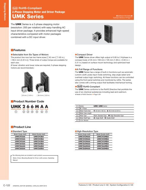
2-Phase Stepping <strong>Motor</strong> and Driver Package<br />
<strong>UMK</strong> <strong>Series</strong><br />
●Additional Information●<br />
Technical reference ➜ Page F-1<br />
The <strong>UMK</strong> <strong>Series</strong> is a 2-phase stepping motor<br />
(resolution: 200 per rotation) with easy-handling AC<br />
input driver package. It provides enhanced high-speed<br />
characteristics compared with motor packages<br />
combined with a DC input driver.<br />
■Features<br />
●Selectable from Six Types of <strong>Motor</strong>s<br />
The product line now has two frame sizes [□42 mm (□1.65 in.),<br />
□56.4 mm (2.22 in.)]. Three kinds of output torque are available for<br />
each size.<br />
(If lower vibration and lower noise are required, 5-phase stepping<br />
motors are recommended.)<br />
□42 mm (□1.65 in.)<br />
□56.4 mm (□2.22 in.)<br />
■Product Number Code<br />
<strong>UMK</strong> 2 6 6 M A A<br />
1 2 3 4 5 6 7<br />
●Compact Driver<br />
The <strong>UMK</strong> <strong>Series</strong> driver offers high output of 0.95 to 2 A/phase in a<br />
compact body of 35 mm×100 mm×135 mm (1.38 in.×3.94 in.×<br />
5.31 in.) based on surface mount technology and optimized heat<br />
design.<br />
●A Full Range of Functions<br />
The <strong>UMK</strong> <strong>Series</strong> has a range of built-in functions such as automatic<br />
current cutoff, pulse input mode switching, step angle select and<br />
overheat output logic switching. All these functions can be controlled<br />
using the front panel switches and monitored by LEDs. The series<br />
also comes with a timing output that facilitates mechanical homing.<br />
● RoHS-Compliant<br />
The <strong>UMK</strong> <strong>Series</strong> conforms to the RoHS Directive that prohibits the<br />
use of six chemical substances including lead and cadmium.<br />
●Details of RoHS Directive ➜ Page G-38<br />
1 <strong>Series</strong> <strong>UMK</strong>: <strong>UMK</strong> <strong>Series</strong><br />
2 2: 2-Phase<br />
3 <strong>Motor</strong> Frame Size 4: 42 mm (1.65 in.) 6: 56.4 mm (2.22 in.)<br />
4 <strong>Motor</strong> Case Length<br />
5 <strong>Motor</strong> Type Blank: Standard Type M: High-Resolution Type<br />
6 <strong>Motor</strong> Shaft Type A: Single Shaft B: Double Shaft<br />
7 U.S.A. Version<br />
■Product Line<br />
●Standard Type<br />
Model (Single shaft)<br />
<strong>UMK</strong>243AA<br />
<strong>UMK</strong>244AA<br />
<strong>UMK</strong>245AA<br />
<strong>UMK</strong>264AA<br />
<strong>UMK</strong>266AA<br />
<strong>UMK</strong>268AA<br />
Model (Double shaft)<br />
<strong>UMK</strong>243BA<br />
<strong>UMK</strong>244BA<br />
<strong>UMK</strong>245BA<br />
<strong>UMK</strong>264BA<br />
<strong>UMK</strong>266BA<br />
<strong>UMK</strong>268BA<br />
●High-Resolution Type<br />
Model (Single shaft) Model (Double shaft)<br />
<strong>UMK</strong>243MAA <strong>UMK</strong>243MBA<br />
<strong>UMK</strong>244MAA <strong>UMK</strong>244MBA<br />
<strong>UMK</strong>245MAA <strong>UMK</strong>245MBA<br />
<strong>UMK</strong>264MAA <strong>UMK</strong>264MBA<br />
<strong>UMK</strong>266MAA <strong>UMK</strong>266MBA<br />
<strong>UMK</strong>268MAA <strong>UMK</strong>268MBA<br />
The following items are included in each product.<br />
<strong>Motor</strong>, Driver, Mounting Bracket for Driver (with screws), Operating<br />
Manual<br />
C-122 ORIENTAL MOTOR GENERAL CATALOG 2009/2010 Features C-122 / Product Line C-122 / System Configuration C-123
■System Configuration<br />
An example of a single-axis system configuration with the EMP400 <strong>Series</strong> controller.<br />
<strong>UMK</strong> <strong>Series</strong><br />
<strong>Motor</strong><br />
Accessories and Peripheral Equipment (Sold separately)<br />
2<strong>Motor</strong> Mounting Brackets<br />
(➜ Page C-312)<br />
●Example of System Configuration<br />
(Sold separately)<br />
<strong>UMK</strong>266BA<br />
EMP401-1<br />
3Flexible Couplings<br />
(➜ Page C-302)<br />
<strong>Motor</strong> Mounting<br />
Bracket<br />
PAL2P-2<br />
Controller (Sold separately)<br />
Driver<br />
Flexible<br />
Coupling<br />
MCS2006F04<br />
1Controller<br />
(➜ Page C-269)<br />
4Clean Dampers<br />
(➜ Page C-310)<br />
D6CL-6.3F<br />
Connector – Terminal<br />
Block Conversion Unit [1 m (3.3 ft.)]<br />
CC50T1<br />
5Connector – Terminal<br />
Block Conversion Unit<br />
(➜ Page C-318)<br />
No. Product Name Overview Page<br />
1 Controller<br />
This controller outputs pulse commands that determine the rotating amount and rotating speed.<br />
C-269<br />
2<br />
3<br />
4<br />
5<br />
<strong>Motor</strong> Mounting Brackets<br />
Flexible Couplings<br />
Clean Dampers<br />
Connector – Terminal Block Conversion Unit<br />
Dedicated mounting bracket for the motor.<br />
Coupling that connects the motor shaft to the driven shaft.<br />
Dedicated damper for suppressing stepping motor vibration.<br />
Set of terminal block and cable (CC50T1) for connecting the EMP <strong>Series</strong> controller and host controller [1 m (3.3 ft.)].<br />
C-312<br />
C-302<br />
C-310<br />
C-318<br />
<strong>UMK</strong> <strong>Series</strong><br />
Controller<br />
Clean Damper<br />
● The system configuration shown above is an example. Other combinations are available.<br />
24 VDC<br />
Power Supply<br />
(Not supplied)<br />
Programmable<br />
Controller<br />
(Not supplied)<br />
AC Power Supply<br />
(Main power supply)<br />
(Not supplied)<br />
AC Input DC Input AC Input DC Input Without Encoder With Encoder Controllers<br />
Stepping <strong>Motor</strong>s Introduction AS ASC<br />
5-Phase<br />
Microstep<br />
RK<br />
2-Phase<br />
Full/Half<br />
<strong>UMK</strong><br />
5-Phase<br />
Microstep<br />
CRK<br />
2-Phase<br />
Microstep<br />
RBK<br />
2-Phase<br />
Microstep<br />
CMK<br />
2-Phase<br />
PK/PV<br />
2-Phase<br />
PK EMP400 SG8030J Accessories Installation<br />
Specifications, Characteristics C-124 / Dimensions C-127 / Connection and Operation C-128 / <strong>Motor</strong> and Driver Combinations C-131<br />
C-123
Stepping <strong>Motor</strong>s<br />
Standard Type <strong>Motor</strong> Frame Size 42 mm (1.65 in.), 56.4 mm (2.22 in.)<br />
■Specifications<br />
Model<br />
Single Shaft <strong>UMK</strong>243AA <strong>UMK</strong>244AA <strong>UMK</strong>245AA <strong>UMK</strong>264AA <strong>UMK</strong>266AA <strong>UMK</strong>268AA<br />
Double Shaft <strong>UMK</strong>243BA <strong>UMK</strong>244BA <strong>UMK</strong>245BA <strong>UMK</strong>264BA <strong>UMK</strong>266BA <strong>UMK</strong>268BA<br />
Maximum Holding Torque N·m (oz-in) 0.16 (22) 0.26 (36) 0.32 (45) 0.39 (55) 0.9 (127) 1.35 (191)<br />
Rotor Inertia J kg·m 2 (oz-in 2 ) 35×10 −7 (0.191) 54×10 −7 (0.3) 68×10 −7 (0.37) 120×10 −7 (0.66) 300×10 −7 (1.64) 480×10 −7 (2.6)<br />
Rated Current A/Phase 0.95 1.2 2<br />
Basic Step Angle 1.8˚<br />
Power Source<br />
Single-Phase 115 VAC±15% 60 Hz or Single-Phase 100 VAC ±15% 50/60 Hz<br />
1 A 1.4 A 2.2 A<br />
Excitation Mode<br />
Mass<br />
Dimension No.<br />
How to read specifications table ➜ Page C-11<br />
Full Step: 1.8˚/step<br />
Half Step: 0.9˚/step<br />
<strong>Motor</strong> kg (lb.) 0.21 (0.46) 0.27 (0.59) 0.35 (0.77) 0.45 (0.99) 0.7 (1.5) 1 (2.2)<br />
Driver kg (lb.) 0.47 (1)<br />
<strong>Motor</strong> □1 □2<br />
Driver<br />
□3<br />
■Speed – Torque Characteristics How to read speed – torque characteristics ➜ Page C-12<br />
<strong>UMK</strong>243AA/<strong>UMK</strong>243BA<br />
Current [A]<br />
3<br />
2<br />
1<br />
0<br />
Torque [oz-in]<br />
30<br />
20<br />
10<br />
0<br />
Torque [N·m]<br />
Power Input: 115 VAC Current: 0.95 A/Phase (2 Phases ON)<br />
With Damper D4CL-5.0F: JL = 34 × 10 −7 kg·m 2 (0.186 oz-in 2 )<br />
0.25<br />
Full Step 1.8˚/step<br />
0.20<br />
Half Step 0.9˚/step<br />
0.15<br />
0.10<br />
0.05<br />
0<br />
0<br />
(0)<br />
fs<br />
Pullout Torque<br />
Driver Input Current<br />
1000 2000 3000 4000<br />
Speed [r/min]<br />
5<br />
10<br />
(10)<br />
(20)<br />
Pulse Speed [kHz]<br />
<strong>UMK</strong>264AA/<strong>UMK</strong>264BA<br />
Current [A]<br />
6<br />
4<br />
2<br />
0<br />
Torque [oz-in]<br />
70<br />
60<br />
50<br />
40<br />
30<br />
20<br />
10<br />
0<br />
Torque [N·m]<br />
Full Step<br />
(Half Step)<br />
Power Input: 115 VAC Current: 2 A/Phase (2 Phases ON)<br />
With Damper D6CL-6.3F: JL = 140 × 10 −7 kg·m 2 (0.77 oz-in 2 )<br />
0.5<br />
Full Step 1.8˚/step<br />
0.4<br />
Half Step 0.9˚/step<br />
0.3<br />
0.2<br />
0.1<br />
0<br />
0<br />
(0)<br />
fs<br />
Pullout Torque<br />
Driver Input Current<br />
1000 2000 3000 4000<br />
Speed [r/min]<br />
5<br />
10<br />
(10)<br />
(20)<br />
Pulse Speed [kHz]<br />
Full Step<br />
(Half Step)<br />
<strong>UMK</strong>244AA/<strong>UMK</strong>244BA<br />
Current [A]<br />
3<br />
2<br />
1<br />
0<br />
Torque [oz-in]<br />
50<br />
40<br />
30<br />
20<br />
10<br />
0<br />
Torque [N·m]<br />
Power Input: 115 VAC Current: 1.2 A/Phase (2 Phases ON)<br />
With Damper D4CL-5.0F: JL = 34 × 10 −7 kg·m 2 ( 0.186 oz-in 2 )<br />
0.35<br />
0.30<br />
Full Step 1.8˚/step<br />
Half Step 0.9˚/step<br />
0.25<br />
0.20<br />
0.15<br />
0.10<br />
0.05<br />
0<br />
0<br />
(0)<br />
fs<br />
Pullout Torque<br />
Driver Input Current<br />
1000 2000 3000 4000<br />
Speed [r/min]<br />
5<br />
10<br />
(10)<br />
(20)<br />
Pulse Speed [kHz]<br />
<strong>UMK</strong>266AA/<strong>UMK</strong>266BA<br />
Current [A]<br />
6<br />
4<br />
2<br />
0<br />
Torque [oz-in]<br />
150<br />
100<br />
50<br />
0<br />
Torque [N·m]<br />
Full Step<br />
(Half Step)<br />
Power Input: 115 VAC Current: 2 A/Phase (2 Phases ON)<br />
With Damper D6CL-6.3F: JL = 140 × 10 −7 kg·m 2 (0.77 oz-in 2 )<br />
1.2<br />
1.0<br />
0.8<br />
0.6<br />
0.4<br />
0.2<br />
0<br />
0<br />
(0)<br />
fs<br />
Driver Input Current<br />
Pullout Torque<br />
1000 2000 3000 4000<br />
Speed [r/min]<br />
5<br />
10<br />
(10)<br />
(20)<br />
Pulse Speed [kHz]<br />
Full Step 1.8˚/step<br />
Half Step 0.9˚/step<br />
Full Step<br />
(Half Step)<br />
<strong>UMK</strong>245AA/<strong>UMK</strong>245BA<br />
Current [A]<br />
4<br />
3<br />
2<br />
1<br />
0<br />
Torque [oz-in]<br />
50<br />
40<br />
30<br />
20<br />
10<br />
0<br />
Torque [N·m]<br />
Power Input: 115 VAC Current: 1.2 A/Phase (2 Phases ON)<br />
With Damper D4CL-5.0F: JL = 34 × 10 −7 kg·m 2 (0.186 oz-in 2 )<br />
0.4<br />
Full Step 1.8˚/step<br />
Half Step 0.9˚/step<br />
0.3<br />
0.2<br />
0.1<br />
0<br />
0<br />
(0)<br />
fs<br />
Pullout Torque<br />
Driver Input Current<br />
1000 2000 3000 4000<br />
Speed [r/min]<br />
5<br />
10<br />
(10)<br />
(20)<br />
Pulse Speed [kHz]<br />
<strong>UMK</strong>268AA/<strong>UMK</strong>268BA<br />
Current [A]<br />
8<br />
6<br />
4<br />
2<br />
0<br />
Torque [oz-in]<br />
200<br />
150<br />
100<br />
50<br />
0<br />
Torque [N·m]<br />
1.4<br />
1.2<br />
1.0<br />
0.8<br />
0.6<br />
0.4<br />
0<br />
0<br />
(0)<br />
5<br />
10<br />
(10)<br />
(20)<br />
Pulse Speed [kHz]<br />
Full Step<br />
(Half Step)<br />
Power Input: 115 VAC Current: 2 A/Phase (2 Phases ON)<br />
With Damper D6CL-6.3F: JL = 140 × 10 −7 kg·m 2 (0.77 oz-in 2 )<br />
1.6<br />
0.2<br />
fs<br />
Pullout Torque<br />
Driver Input Current<br />
Full Step 1.8˚/step<br />
Half Step 0.9˚/step<br />
1000 2000 3000 4000<br />
Speed [r/min]<br />
Full Step<br />
(Half Step)<br />
●The pulse input circuit responds up to approximately 20 kHz with a pulse duty of 50%.<br />
Notes:<br />
●Pay attention to heat dissipation from motor and driver. In particular, remember that the motor will produce a considerable amount of heat under certain conditions. Be sure to keep the temperature of<br />
the motor case under 100˚C (212˚F).<br />
●The driver's automatic current cutback function at motor standstill reduces maximum holding torque by approximately 40%.<br />
C-124 ORIENTAL MOTOR GENERAL CATALOG 2009/2010 Features C-122 / Product Line C-122 / System Configuration C-123
High-Resolution Type <strong>Motor</strong> Frame Size 42 mm (1.65 in.), 56.4 mm (2.22 in.)<br />
■Specifications<br />
Model<br />
Single Shaft <strong>UMK</strong>243MAA <strong>UMK</strong>244MAA <strong>UMK</strong>245MAA <strong>UMK</strong>264MAA <strong>UMK</strong>266MAA <strong>UMK</strong>268MAA<br />
Double Shaft <strong>UMK</strong>243MBA <strong>UMK</strong>244MBA <strong>UMK</strong>245MBA <strong>UMK</strong>264MBA <strong>UMK</strong>266MBA <strong>UMK</strong>268MBA<br />
Maximum Holding Torque N·m (oz-in) 0.16 (22) 0.26 (36) 0.32 (45) 0.39 (55) 0.9 (127) 1.35 (191)<br />
Rotor Inertia J kg·m 2 (oz-in 2 ) 35×10 −7 (0.191) 54×10 −7 (0.3) 68×10 −7 (0.37) 120×10 −7 (0.66) 300×10 −7 (1.64) 480×10 −7 (2.6)<br />
Rated Current A/Phase 0.95 1.2 2<br />
Basic Step Angle 0.9˚<br />
Power Source<br />
Single-Phase 115 VAC±15% 60 Hz or Single-Phase 100 VAC ±15% 50/60 Hz<br />
1 A 1.4 A 2.2 A<br />
Excitation Mode<br />
Mass<br />
Dimension No.<br />
How to read specifications table ➜ Page C-11<br />
Full Step: 0.9˚/step<br />
Half Step: 0.45˚/step<br />
<strong>Motor</strong> kg (lb.) 0.24 (0.53) 0.3 (0.66) 0.37 (0.81) 0.45 (0.99) 0.7 (1.5) 1 (2.2)<br />
Driver kg (lb.) 0.47 (1)<br />
<strong>Motor</strong> □1 □2<br />
Driver<br />
□3<br />
■Speed – Torque Characteristics How to read speed – torque characteristics ➜ Page C-12<br />
<strong>UMK</strong>243MAA/<strong>UMK</strong>243MBA<br />
Current [A]<br />
1.5<br />
1<br />
0.5<br />
0<br />
Torque [oz-in]<br />
30<br />
20<br />
10<br />
0<br />
Torque [N·m]<br />
Power Input: 115 VAC Current: 0.95 A/Phase (2 Phases ON)<br />
With Damper D4CL-5.0F: JL = 34 × 10 −7 kg·m 2 (0.186 oz-in 2 )<br />
0.25<br />
0.20<br />
0.15<br />
0.10<br />
0.05<br />
0<br />
0<br />
(0)<br />
Driver Input Current<br />
fs<br />
Pullout Torque<br />
1000 2000 3000 4000<br />
Speed [r/min]<br />
10<br />
20<br />
(20)<br />
(40)<br />
Pulse Speed [kHz]<br />
<strong>UMK</strong>264MAA/<strong>UMK</strong>264MBA<br />
Current [A]<br />
3<br />
2<br />
1<br />
0<br />
Torque [oz-in]<br />
70<br />
60<br />
50<br />
40<br />
30<br />
20<br />
10<br />
0<br />
Torque [N·m]<br />
Full Step 0.9˚/step<br />
Half Step 0.45˚/step<br />
Full Step<br />
(Half Step)<br />
<strong>UMK</strong>244MAA/<strong>UMK</strong>244MBA<br />
Current [A]<br />
Power Input: 115 VAC Current: 2 A/Phase (2 Phases ON)<br />
With Damper D6CL-6.3F: JL = 140 × 10 −7 kg·m 2 (0.77 oz-in 2 )<br />
0.5<br />
Full Step 0.9˚/step<br />
0.4<br />
Half Step 0.45˚/step<br />
0.3<br />
0.2<br />
0.1<br />
0<br />
fs<br />
0<br />
(0)<br />
Pullout Torque<br />
Driver Input Current<br />
1000 2000 3000 4000<br />
Speed [r/min]<br />
10<br />
20<br />
(20)<br />
(40)<br />
Pulse Speed [kHz]<br />
Full Step<br />
(Half Step)<br />
1.5<br />
1<br />
0.5<br />
0<br />
Torque [oz-in]<br />
50<br />
40<br />
30<br />
20<br />
10<br />
0<br />
Torque [N·m]<br />
Power Input: 115 VAC Current: 1.2 A/Phase (2 Phases ON)<br />
With Damper D4CL-5.0F: JL = 34 × 10 −7 kg·m 2 (0.186 oz-in 2 )<br />
0.35<br />
0.30<br />
Full Step 0.9˚/step<br />
Half Step 0.45˚/step<br />
0.25<br />
0.20<br />
0.15<br />
0.10<br />
Driver Input Current<br />
0.05<br />
0<br />
fs<br />
1000 2000 3000 4000<br />
Speed [r/min]<br />
0<br />
(0)<br />
Pullout Torque<br />
10<br />
20<br />
(20)<br />
(40)<br />
Pulse Speed [kHz]<br />
<strong>UMK</strong>266MAA/<strong>UMK</strong>266MBA<br />
Current [A]<br />
3<br />
2<br />
1<br />
0<br />
Torque [oz-in]<br />
150<br />
100<br />
50<br />
0<br />
Torque [N·m]<br />
0<br />
0<br />
(0)<br />
1000 2000 3000 4000<br />
Speed [r/min]<br />
10<br />
20<br />
(20)<br />
(40)<br />
Pulse Speed [kHz]<br />
●The pulse input circuit responds up to approximately 20 kHz with a pulse duty of 50%.<br />
Notes:<br />
●Pay attention to heat dissipation from motor and driver. In particular, remember that the motor will produce a considerable amount of heat under certain conditions. Be sure to keep the temperature of<br />
the motor case under 100˚C (212˚F).<br />
●The driver's automatic current cutback function at motor standstill reduces maximum holding torque by approximately 40%.<br />
Full Step<br />
(Half Step)<br />
Power Input: 115 VAC Current: 2 A/Phase (2 Phases ON)<br />
With Damper D6CL-6.3F: JL = 140 × 10 −7 kg·m 2 (0.77 oz-in 2 )<br />
1.2<br />
1.0<br />
0.8<br />
0.6<br />
Pullout Torque<br />
0.4<br />
Driver Input Current<br />
0.2<br />
fs<br />
Full Step 0.9˚/step<br />
Half Step 0.45˚/step<br />
Full Step<br />
(Half Step)<br />
<strong>UMK</strong>245MAA/<strong>UMK</strong>245MBA<br />
Current [A]<br />
2<br />
30<br />
0.2<br />
1<br />
0<br />
Torque [oz-in]<br />
50<br />
40<br />
20<br />
10<br />
0<br />
Torque [N·m]<br />
Power Input: 115 VAC Current: 1.2 A/Phase (2 Phases ON)<br />
With Damper D4CL-5.0F: JL = 34 × 10 −7 kg·m 2 (0.186 oz-in 2 )<br />
0.4<br />
Full Step 0.9˚/step<br />
Half Step 0.45˚/step<br />
0.3<br />
0.1<br />
0<br />
fs<br />
0<br />
(0)<br />
Pullout Torque<br />
Driver Input Current<br />
1000 2000 3000 4000<br />
Speed [r/min]<br />
10<br />
20<br />
(20)<br />
(40)<br />
Pulse Speed [kHz]<br />
<strong>UMK</strong>268MAA/<strong>UMK</strong>268MBA<br />
Current [A]<br />
4<br />
3<br />
2<br />
1<br />
0<br />
Torque [oz-in]<br />
200<br />
150<br />
100<br />
50<br />
0<br />
Torque [N·m]<br />
1.4<br />
1.2<br />
1.0<br />
0.8<br />
0.6<br />
Full Step<br />
(Half Step)<br />
Power Input: 115 VAC Current: 2 A/Phase (2 Phases ON)<br />
With Damper D6CL-6.3F: JL = 140 × 10 −7 kg·m 2 (0.77 oz-in 2 )<br />
1.6<br />
Pullout Torque<br />
Full Step 0.9˚/step<br />
Half Step 0.45˚/step<br />
0.4<br />
Driver Input Current<br />
0.2<br />
0<br />
fs<br />
1000 2000 3000 4000<br />
Speed [r/min]<br />
0<br />
10<br />
20 Full Step<br />
(0)<br />
(20)<br />
(40) (Half Step)<br />
Pulse Speed [kHz]<br />
AC Input DC Input AC Input DC Input Without Encoder With Encoder Controllers<br />
Stepping <strong>Motor</strong>s Introduction AS ASC<br />
5-Phase<br />
Microstep<br />
RK<br />
2-Phase<br />
Full/Half<br />
<strong>UMK</strong><br />
5-Phase<br />
Microstep<br />
CRK<br />
2-Phase<br />
Microstep<br />
RBK<br />
2-Phase<br />
Microstep<br />
CMK<br />
2-Phase<br />
PK/PV<br />
2-Phase<br />
PK EMP400 SG8030J Accessories Installation<br />
Specifications, Characteristics C-124 / Dimensions C-127 / Connection and Operation C-128 / <strong>Motor</strong> and Driver Combinations C-131<br />
C-125
Stepping <strong>Motor</strong>s<br />
■Driver Specifications<br />
Input<br />
Signals<br />
Output<br />
Signals<br />
Functions<br />
Indicators (LED)<br />
Cooling Method<br />
Input Mode<br />
Pulse Signal<br />
(CW Pulse Signal)<br />
Rotation Direction Signal<br />
(CCW Pulse Signal)<br />
All Windings Off Signal<br />
Output Mode<br />
Excitation Timing Signal<br />
Overheat Signal<br />
Photocoupler input, Input resistance: 220 Ω, Input current: 7∼20 mA<br />
Photocoupler ON: +4.5∼5 V, Photocoupler OFF: 0∼+1 V (Voltage between terminals)<br />
Operation command pulse signal (CW direction operation command pulse signal when in 2-pulse input mode), Negative logic pulse input<br />
Pulse width: 5 μs minimum, Pulse rise/fall: 2 μs maximum, Pulse duty: 50% and below<br />
<strong>Motor</strong> moves one step when the pulse input is switched from photocoupler ON to OFF.<br />
Maximum input pulse frequency: 20 kHz (When the pulse duty is 50%)<br />
Rotation direction signal, Photocoupler ON: CW, Photocoupler OFF: CCW<br />
CCW direction operation command pulse signal when in 2-pulse input mode, Negative logic pulse input<br />
Pulse width: 5 μs minimum, Pulse rise/fall: 2 μs maximum, Pulse duty: 50% and below<br />
<strong>Motor</strong> moves one step when the pulse input is switched from photocoupler ON to OFF.<br />
Maximum input pulse frequency: 20 kHz (When the pulse duty is 50%)<br />
When in the "photocoupler ON" state, the output current to the motor is cut off and the motor shaft can be rotated manually.<br />
When in the "photocoupler OFF" state, the current is supplied to the motor.<br />
Photocoupler, Open-collector output<br />
External use condition: 24 VDC maximum, 10 mA maximum<br />
The signal is output every time the excitation sequence returns to the initial stage "0." (Photocoupler: ON)<br />
Full step: Signal is output every 4 pulses, Half step: Signal is output every 8 pulses<br />
The signal is output when the temperature of the driver heat sink rises above approximately 90˚C (194˚F). (Photocoupler: ON or OFF, automatic<br />
return available)<br />
The motor current is cut off automatically if the automatic current off function is ON.<br />
The output logic of the photocoupler is based on the setting of the overheat output logic switch.<br />
Automatic current cutback, Automatic current Off, Pulse mode input switch, Step angle select, Overheat output logic switch<br />
Power supply input, CW/PLS input, CCW/DIR input, All windings off input, Excitation timing output, Overheat output<br />
Natural ventilation<br />
■General Specifications<br />
Item <strong>Motor</strong> Driver<br />
Insulation Class Class B [130˚C (266˚F)] −<br />
Insulation Resistance<br />
Insulation Strength<br />
Operating<br />
Environment<br />
Temperature Rise<br />
100 MΩ or more when 500 VDC megger is applied between the windings<br />
and the case under normal ambient temperature and humidity.<br />
Sufficient to withstand 1.0 kVAC (0.5 kVAC for <strong>UMK</strong>24□ and<br />
<strong>UMK</strong>24M□ types) at 50 Hz or 60 Hz applied between the windings and<br />
the case for 1 minute under normal ambient temperature and humidity.<br />
100 MΩ or more when 500 VDC megger is applied between the following<br />
places under normal ambient temperature and humidity:<br />
· Case − Power input terminal<br />
· Case − Signal I/O terminal<br />
· Power input terminal − Signal I/O terminal<br />
Sufficient to withstand the following for 1 minute under normal ambient<br />
temperature and humidity:<br />
· Case − Power input terminal 1.0 kVAC 50 Hz or 60 Hz<br />
· Case − Signal I/O terminal 1.0 kVAC 50 Hz or 60 Hz<br />
· Power input terminal − Signal I/O terminal 1.0 kVAC 50 Hz or 60 Hz<br />
Ambient Temperature −10∼+50˚C (+14∼+122˚F) (non-freezing) 0∼+40˚C (+32∼+104˚F) (non-freezing)<br />
Ambient Humidity<br />
85% or less (non-condensing)<br />
Atmosphere<br />
No corrosive gases, dust, water or oil<br />
Temperature rise of the windings is 80˚C (144˚F) or less measured by the<br />
resistance change method. (at rated voltage, at standstill, two phases<br />
−<br />
energized)<br />
Stop Position Accuracy ✽1 ±3 arc minutes (±0.05˚) −<br />
Shaft Runout 0.05 mm (0.002 in.) T.I.R. ✽4 −<br />
Radial Play ✽2 0.025 mm (0.001 in.) maximum of 5 N (1.12 lb.) −<br />
Axial Play ✽3 0.075 mm (0.003 in.) maximum of 10 N (2.2 lb.) −<br />
Concentricity 0.075 mm (0.003 in.) T.I.R. ✽4 −<br />
Perpendicularity 0.075 mm (0.003 in.) T.I.R. ✽4 −<br />
✽ 1 This value is for full step under no load. (The value changes with the size of the load.)<br />
✽ 2 Radial Play: Displacement in shaft position in the radial direction, when a 5 N (1.12 lb.) load is applied in the vertical direction to the tip of the motor's<br />
shaft.<br />
✽ 3 Axial Play: Displacement in shaft position in the axial direction, when a 10 N (2.2 lb.) load is applied to the motor's shaft in the axial direction.<br />
✽ 4 T.I.R. (Total Indicator Reading): The total dial gauge reading when the measurement section is rotated one revolution centered on a reference axis<br />
center.<br />
Note:<br />
●Do not measure insulation resistance or perform the dielectric strength test while the motor and driver are connected.<br />
ϕ0.075<br />
A<br />
0.05<br />
A<br />
0.075<br />
A<br />
C-126 ORIENTAL MOTOR GENERAL CATALOG 2009/2010 Features C-122 / Product Line C-122 / System Configuration C-123
■Permissible Overhung Load and Permissible Thrust Load<br />
Model<br />
<strong>UMK</strong>243□A, <strong>UMK</strong>243□MA<br />
<strong>UMK</strong>244□A, <strong>UMK</strong>244□MA<br />
<strong>UMK</strong>245□A, <strong>UMK</strong>245□MA<br />
<strong>UMK</strong>264□A, <strong>UMK</strong>264□MA<br />
<strong>UMK</strong>266□A, <strong>UMK</strong>266□MA<br />
<strong>UMK</strong>268□A, <strong>UMK</strong>268□MA<br />
●Enter<br />
A (single shaft) or B (double shaft) in the box (□) within the model name.<br />
■Dimensions<br />
●<strong>Motor</strong><br />
Unit = mm (in.)<br />
◇Standard Type, High-Resolution Type<br />
□1 □42 mm (□1.65 in.)<br />
Mass<br />
Model <strong>Motor</strong> Model L1 L2<br />
kg (lb.)<br />
<strong>UMK</strong>243AA PK243-01AA<br />
0.21 (0.46)<br />
−<br />
<strong>UMK</strong>243MAA PK243MAA 0.24 (0.53)<br />
33 (1.3)<br />
<strong>UMK</strong>243BA PK243-01BA<br />
0.21 (0.46)<br />
48 (1.89)<br />
<strong>UMK</strong>243MBA PK243MBA 0.24 (0.53)<br />
<strong>UMK</strong>244AA PK244-01AA<br />
0.27 (0.59)<br />
−<br />
<strong>UMK</strong>244MAA PK244MAA 0.3 (0.66)<br />
39 (1.54)<br />
<strong>UMK</strong>244BA PK244-01BA<br />
0.27 (0.59)<br />
54 (2.13)<br />
<strong>UMK</strong>244MBA PK244MBA 0.3 (0.66)<br />
<strong>UMK</strong>245AA PK245-01AA<br />
0.35 (0.77)<br />
−<br />
<strong>UMK</strong>245MAA PK245MAA 0.37 (0.81)<br />
47 (1.85)<br />
<strong>UMK</strong>245BA PK245-01BA<br />
0.35 (0.77)<br />
62 (2.44)<br />
<strong>UMK</strong>245MBA PK245MBA 0.37 (0.81)<br />
□2 □56.4 mm (□2.22 in.)<br />
Model <strong>Motor</strong> Model L1 L2<br />
<strong>UMK</strong>264AA<br />
<strong>UMK</strong>264MAA<br />
<strong>UMK</strong>264BA<br />
<strong>UMK</strong>264MBA<br />
<strong>UMK</strong>266AA<br />
<strong>UMK</strong>266MAA<br />
<strong>UMK</strong>266BA<br />
<strong>UMK</strong>266MBA<br />
<strong>UMK</strong>268AA<br />
<strong>UMK</strong>268MAA<br />
<strong>UMK</strong>268BA<br />
<strong>UMK</strong>268MBA<br />
PK264-02A<br />
PK264MA<br />
PK264-02B<br />
PK264MB<br />
PK266-02A<br />
PK266MA<br />
PK266-02B<br />
PK266MB<br />
PK268-02A<br />
PK268MA<br />
PK268-02B<br />
PK268MB<br />
Permissible Overhung Load<br />
Distance from Shaft End<br />
0 mm (0 in.) 5 mm (0.2 in.) 10 mm (0.39 in.) 15 mm (0.59 in.) 20 mm (0.79 in.)<br />
20 (4.5) 25 (5.6) 34 (7.6) 52 (11.7) −<br />
54 (12.1) 67 (15) 89 (20) 130 (29) −<br />
39 (1.54)<br />
54 (2.13)<br />
76 (2.99)<br />
−<br />
55 (2.17)<br />
−<br />
70 (2.76)<br />
−<br />
92 (3.62)<br />
Mass<br />
kg (lb.)<br />
DXF<br />
B081U<br />
B082U<br />
B083U<br />
DXF<br />
0.45 (0.99) B084<br />
0.7 (1.5) B085<br />
1 (2.2) B086<br />
ϕ6.35−0.012<br />
0<br />
16±1 (0.63±0.04)<br />
15±0.25<br />
(0.591±0.010)<br />
0<br />
( 0.2500−0.0005 1/4 )<br />
5.8±0.15<br />
(0.228±0.006)<br />
0<br />
ϕ5−0.012<br />
✽15±1<br />
(0.59±0.04)<br />
0<br />
( 0.1969−0.0005 )<br />
4.5±0.15<br />
(0.177±0.006)<br />
L2<br />
L1<br />
20±1<br />
(0.79±0.04)<br />
15±0.25<br />
(0.591±0.010)<br />
2 (0.08)<br />
6 <strong>Motor</strong> Leads 300 mm (12 in.) Length<br />
UL Style 3265, AWG24<br />
Permissible Thrust Load<br />
The permissible thrust load shall be<br />
no greater than the motor mass.<br />
4.5±0.15 (0.177±0.006)<br />
0 0<br />
( 0.1969−0.0005 )<br />
0<br />
( 0.8661−0.0013)<br />
ϕ5−0.012<br />
0<br />
ϕ22−0.033<br />
✽The length of machining on the double shaft model is 15±0.25 (0.591±0.010).<br />
L2 20±1 (0.79±0.04)<br />
L1<br />
5 (0.20) 1.6 (0.06)<br />
15±0.25<br />
(0.591±0.010)<br />
5.8±0.15 (0.228±0.006)<br />
0<br />
0<br />
ϕ6.35−0.012 ( 0.2500−0.0005 1/4 )<br />
ϕ38.1±0.03 ( 1.5000±0.0012)<br />
6 <strong>Motor</strong> Leads 300 mm (12 in.) Length<br />
UL Style 3265, AWG22<br />
42 (1.65)<br />
Unit = N (lb.)<br />
31±0.2<br />
(1.220±0.008)<br />
31±0.2<br />
(1.220±0.008)<br />
42 (1.65)<br />
4×No.4-40 UNC×4.5 (0.18) Deep<br />
56.4 (2.22)<br />
47.14±0.35<br />
(1.86±0.014)<br />
4×ϕ4.5 (ϕ0.177) Thru<br />
47.14±0.35<br />
(1.86±0.014)<br />
56.4 (2.22)<br />
AC Input DC Input AC Input DC Input Without Encoder With Encoder Controllers<br />
Stepping <strong>Motor</strong>s Introduction AS ASC<br />
5-Phase<br />
Microstep<br />
RK<br />
2-Phase<br />
Full/Half<br />
<strong>UMK</strong><br />
5-Phase<br />
Microstep<br />
CRK<br />
2-Phase<br />
Microstep<br />
RBK<br />
2-Phase<br />
Microstep<br />
CMK<br />
2-Phase<br />
PK/PV<br />
2-Phase<br />
PK EMP400 SG8030J Accessories Installation<br />
● These dimensions are for the double shaft models. For the single shaft models, ignore the orange (<br />
) areas.<br />
Specifications, Characteristics C-124 / Dimensions C-127 / Connection and Operation C-128 / <strong>Motor</strong> and Driver Combinations C-131<br />
C-127
Stepping <strong>Motor</strong>s<br />
●Driver<br />
□3 UDK2109A, UDK2112A, UDK2120A<br />
Mass: 0.47 kg (1 lb.)<br />
B087<br />
10 (0.39)<br />
15<br />
(0.59)<br />
15<br />
(0.591)<br />
80 (3.15)<br />
45<br />
(1.77)<br />
10 (0.39)<br />
14<br />
(0.55)<br />
12×M3<br />
Upper Bottom Line Symmetry<br />
●Mounting Bracket A<br />
(2 pieces, included)<br />
15±0.3 (0.591±0.012)<br />
15<br />
(0.59)<br />
10<br />
(0.39)<br />
2×ϕ3.5 (ϕ0.138) Countersink<br />
Slits<br />
17.5 (0.69)<br />
100 (3.94)<br />
135 (5.31)<br />
2×M3<br />
Terminal Block Cover<br />
18 (0.71) max.<br />
2 (0.08) max.<br />
35<br />
(1.38)<br />
7.62 (0.3)<br />
6.32 (0.25)<br />
17×M3<br />
15 (0.59)<br />
7.5<br />
(0.30)<br />
35<br />
(1.38)<br />
●Mounting Bracket B<br />
(2 pieces, included)<br />
7.5 (0.30)<br />
4.5 (0.18) 2 (0.08)<br />
20±0.3 (0.787±0.012)<br />
20±0.3 (0.787±0.012)<br />
4.5<br />
(0.18)<br />
2 (0.08)<br />
28<br />
(1.1)<br />
70 (2.756)<br />
15 (0.59)<br />
5 (0.2)<br />
35 (1.38)<br />
2×ϕ3.5 (ϕ0.138) Countersink<br />
15±0.3 (0.591±0.012)<br />
■Connection and Operation<br />
●Names and Functions of Driver Parts<br />
□1<br />
□4<br />
□1 Signal Monitor Displays<br />
Indication Color Function<br />
POWER Green Power input display<br />
CW/PLS Green Pulse/CW pulse input display<br />
CCW/DIR. Green Rotation direction/CCW pulse input display<br />
C.OFF Green All windings off input display<br />
TIMING Green Excitation timing output display<br />
O.H. Red Overheat output display<br />
□2 Current Adjustment Switches<br />
Indication Switch Name Condition<br />
RUN <strong>Motor</strong> Run Current Switch For adjusting the motor running current.<br />
STOP <strong>Motor</strong> Stop Current Switch For adjusting the motor current at standstill.<br />
□2<br />
□3<br />
<strong>Motor</strong> Terminals<br />
Power Input<br />
Terminals<br />
□3 Function Select Switches<br />
Indication Switch Name Function<br />
ON/ACD<br />
ON/ACO<br />
F/H<br />
2P/1P<br />
N.O./N.C.<br />
Automatic current cutback<br />
function switch<br />
Automatic current off<br />
function switch<br />
Step angle select switch<br />
Pulse input mode switch<br />
Overheat output<br />
logic switch<br />
□4 Input/Output Signals<br />
Input/Output Signal Name Function<br />
CW pulse signal (Pulse signal) Operation command pulse signal (The motor will rotate in the CW direction when in 2-pulse input mode.)<br />
Input<br />
CCW pulse signal<br />
(Rotation direction signal)<br />
All windings off signal<br />
Rotation direction signal, Photocoupler OFF: CCW; Photocoupler ON: CW<br />
(The motor will rotate in the CCW direction when in 2-pulse input mode.)<br />
Cuts the output current to the motor and allows the motor shafts to be rotated by external force.<br />
Excitation timing signal Outputs signals when the excitation sequence is at STEP "0."<br />
Output<br />
Overheat signal When the temperature of the driver heat sink rises above 90˚C (194˚F), this signal will be output.<br />
Description of input/output signals ➜ Page C-130<br />
Automatically decreases output current to<br />
motor at motor standstill.<br />
When the temperature of the driver heat<br />
sink rises above 90˚C (194˚F), this function<br />
automatically switches the motor current off. The<br />
function can be set and released with this switch.<br />
Switches the motor's step angle.<br />
Standard type F: 1.8˚/step, H: 0.9˚/step<br />
High-resolution type F: 0.9˚/step, H: 0.45˚/step<br />
Switches between 1-pulse input and<br />
2-pulse input.<br />
Select overheat alarm logic.<br />
N.O.: Normally open<br />
N.C.: Normally closed<br />
Use according to your equipment.<br />
C-128 ORIENTAL MOTOR GENERAL CATALOG 2009/2010 Features C-122 / Product Line C-122 / System Configuration C-123
●Connection Diagram<br />
0 V<br />
0 V<br />
0 V<br />
Controller<br />
V0(+5∼24V)<br />
V0(+5∼24V)<br />
0 V<br />
Twisted-Pair Wire<br />
Pulse Signal<br />
(CW Pulse Signal)<br />
R1<br />
Rotation Direction Signal<br />
(CCW Pulse Signal)<br />
R1<br />
All Windings Off Signal<br />
R1<br />
R2<br />
Excitation Timing Signal<br />
R2<br />
Overheat Signal<br />
Single-Phase 115 VAC±15% 60 Hz<br />
or<br />
Single-Phase 100 VAC±15% 50/60 Hz<br />
+CW/PLS<br />
−CW/PLS<br />
+CCW/DIR.<br />
−CCW/DIR.<br />
+C.OFF<br />
−C.OFF<br />
+TIMING<br />
+O.HEAT<br />
−COM<br />
AC100V/115V<br />
AC100V/115V<br />
FG<br />
Ground (Use wire of AWG18 or thicker.)<br />
Driver<br />
Input<br />
Signals<br />
Output<br />
Signals<br />
YELLOW<br />
/WHITE<br />
BLACK<br />
RED<br />
GREEN<br />
BLUE<br />
<strong>Motor</strong> Leads<br />
Yellow<br />
White<br />
Black<br />
Red<br />
Green<br />
◇Input Signal Connection<br />
Signals can be connected directly when 5 VDC is supplied. If the signals are used at a voltage<br />
exceeding 5 VDC, be sure to provide an external resistor to prevent the current exceeding 20 mA<br />
from flowing. Internal components will be damaged if a voltage exceeding 5 VDC is supplied<br />
directly without using an external resistor.<br />
Example: If the voltage is 24 VDC, connect a resistor (R1) of 1.5 to 2.2 kΩ and 0.5 W or more.<br />
◇Output Signal Connection<br />
Use output signals at 24 VDC or less and 10 mA or less.<br />
If these specifications are exceeded, the internal components may be damaged.<br />
Check the specification of the connected equipment.<br />
When the current is above 10 mA, connect an external resistor R2.<br />
◇Power Supply<br />
Use a power supply that can supply sufficient input current. When power supply capacity is<br />
insufficient, a decrease in motor output can cause the following malfunctions:<br />
●<strong>Motor</strong> does not operate properly at high-speed.<br />
●Slow motor startup and stopping<br />
Blue<br />
2-Phase Stepping <strong>Motor</strong><br />
◇Notes on Wiring<br />
●Use twisted-pair wires of AWG24 or thicker and keep wiring as short as possible [within 2 m<br />
(6.6 ft.)].<br />
●Note that as the length of the pulse signal line increases, the maximum transmission<br />
frequency decreases. Technical reference ➜ Page F-54<br />
●Use wires of AWG20 or thicker for motor line (when extended) and power supply lines, and<br />
use wire of AWG18 or thicker for protective earth line.<br />
●To ground the driver and controller, lead the ground conductor form the protective earth<br />
terminal and connect the ground conductor to provide a common ground point.<br />
●Provide a minimum distance of 10 cm (3.9 in.) between the signal lines and power lines (AC<br />
lines, motor lines and other large-current circuits).<br />
Do not run the signal lines in the same duct as power lines or bundle them with power lines.<br />
◇Recommended Crimp Terminals<br />
6.2 (0.24) max.<br />
3.2 (0.13) min.<br />
9 (0.35) min.<br />
6.2 (0.24) max.<br />
Unit = mm (in.)<br />
3.2 (0.13) min.<br />
9 (0.35) min.<br />
●Crimp terminals are not provided with the products. They must be purchased separately.<br />
AC Input DC Input AC Input DC Input Without Encoder With Encoder Controllers<br />
Stepping <strong>Motor</strong>s Introduction AS ASC<br />
5-Phase<br />
Microstep<br />
RK<br />
2-Phase<br />
Full/Half<br />
<strong>UMK</strong><br />
5-Phase<br />
Microstep<br />
CRK<br />
2-Phase<br />
Microstep<br />
RBK<br />
2-Phase<br />
Microstep<br />
CMK<br />
2-Phase<br />
PK/PV<br />
2-Phase<br />
PK EMP400 SG8030J Accessories Installation<br />
Specifications, Characteristics C-124 / Dimensions C-127 / Connection and Operation C-128 / <strong>Motor</strong> and Driver Combinations C-131<br />
C-129
Stepping <strong>Motor</strong>s<br />
●Description of Input/Output Signals<br />
Indication of Input/Output Signal "ON""OFF"<br />
Input (output) "ON" indicates that the current is sent into the<br />
photocoupler (transistor) inside the driver. Input (output)<br />
"OFF" indicates that the current is not sent into the<br />
photocoupler (transistor) inside the driver. The input/output<br />
remains "OFF" if nothing is connected.<br />
Photocoupler OFF ON<br />
Pulse (CW) and Rotation Direction (CCW) Input Signal<br />
All Windings Off (C.OFF) Input Signal<br />
◇Input Circuit and Sample Connection<br />
Controller<br />
Driver<br />
Open-Collector<br />
Output<br />
R1<br />
VO<br />
0 V<br />
+<br />
−<br />
220 Ω<br />
7∼20 mA<br />
◇Pulse (CW) and Rotation Direction (CCW) Input Signal<br />
Pulse Waveform Characteristics<br />
● 1-Pulse Input Mode<br />
ON<br />
Pulse<br />
OFF<br />
90%<br />
10%<br />
✽1<br />
5 μs<br />
min.<br />
5 μs<br />
min.<br />
✽2<br />
50 μs 50 μs<br />
min. min.<br />
◇All Windings Off (C.OFF) Input Signal<br />
● Inputting this signal puts the motor in a non-excitation (free) state.<br />
● This signal is used when moving the motor by external force or<br />
manual home position is desired. The photocoupler must be<br />
"OFF" when operating the motor.<br />
All Windings<br />
Off Signal<br />
<strong>Motor</strong> Current<br />
ON<br />
OFF<br />
<strong>Motor</strong> Holding Torque<br />
ON<br />
ON<br />
OFF<br />
Release<br />
The shaded area indicates that the motor provides holding torque in proportion to standstill<br />
current set by STOP switch.<br />
● Switching the "All Windings Off" (C.OFF) signal from "photocoupler<br />
ON" to "photocoupler OFF" does not alter the excitation sequence.<br />
When the motor shaft is manually adjusted with the "All Windings<br />
Off" signal input, the shaft will shift up to ±3.6˚ from the position<br />
set after the "All Windings Off" signal is released.<br />
Excitation Timing (TIMING) Output Signal<br />
Overheat (O.HEAT) Output Signal<br />
◇Output Circuit and Sample Connection<br />
Controller<br />
Driver<br />
ON<br />
Rotation Direction<br />
OFF<br />
● 2-Pulse Input Mode<br />
ON<br />
CW Pulse<br />
OFF<br />
ON<br />
CCW Pulse<br />
OFF<br />
2 μs max. 2 μs max.<br />
90%<br />
10%<br />
5 μs<br />
✽1<br />
5 μs<br />
CCW<br />
min. min.<br />
2 μs max. 2 μs max.<br />
✽2<br />
50 μs min.<br />
CW<br />
Pulse duty: 50% and below<br />
✽ 1 The shaded area indicates that the photocoupler diode is ON. The motor moves when the<br />
photocoupler state changes from ON to OFF.<br />
✽ 2 The minimum interval time when changing rotation direction is 50 μs. This value varies<br />
greatly depending on the motor type and load inertia.<br />
◇Pulse Signal Characteristics<br />
● Keep the "Pulse" signal at the "photocoupler OFF" state when no<br />
pulses are being input.<br />
● In 1-pulse input mode, leave the pulse signal at rest ("photocoupler<br />
OFF") when changing rotation directions.<br />
● In 2-pulse input mode, do not input a CW pulse and CCW pulse<br />
simultaneously.<br />
VO<br />
R2<br />
0 V<br />
+<br />
−<br />
10 mA max.<br />
◇Excitation Timing (TIMING) Output Signal<br />
● The "Excitation Timing" signal is output when the motor excitation<br />
is in the initial stage (step "0").<br />
● The "Excitation Timing" signal is output simultaneously with a pulse<br />
input each time the excitation sequence returns to step "0." The<br />
excitation sequence will complete one cycle for every 7.2˚ rotation<br />
of the motor output shaft.<br />
Full step: Signal is output once every 4 pulses.<br />
Half step: Signal is output once every 8 pulses.<br />
The TIMING LED lights on the front panel when the "Excitation<br />
Timing" signal is output.<br />
Timing chart at 1.8˚/step (full step)<br />
✽ When connected as shown in the sample connection, the signal will be "photocoupler ON" at<br />
step "0."<br />
Output Signal ✽ OFF<br />
Pulse<br />
Input Signal<br />
ON<br />
OFF<br />
1 2 3 4 5 6 7 8 9 10 11 12 1314<br />
Rotation Direction ON<br />
Input Signal OFF<br />
CW<br />
CCW<br />
Excitation Timing ON<br />
(Step) 0 1 2 3 0 1 2 3 0 1 2 3 2 1 0<br />
Note:<br />
●When power is turned on, the excitation sequence is reset to step "0" and the "Excitation<br />
Timing" signal will be output.<br />
C-130 ORIENTAL MOTOR GENERAL CATALOG 2009/2010 Features C-122 / Product Line C-122 / System Configuration C-123
◇Overheat (O.HEAT) Output Signal<br />
● The "Overheat" signal is output to protect the driver from heat<br />
damage if the internal temperature of the driver heat sink rises<br />
above 90˚C (194˚F). The O.H. LED lights on the front panel when<br />
the "Overheat" signal is output.<br />
● When used as shown in the sample connection with the<br />
overheat output logic switch set to "N.O.", the signal becomes<br />
"photocoupler ON." (Switch to "N.C." to set to the "photocoupler<br />
OFF.")<br />
● You can select whether to stop the motor or continue the<br />
operation when an "Overheat" signal is output.<br />
● If the automatic current off function switch is set to ACO position,<br />
output current is cut off to stop the motor when the "Overheat"<br />
signal is output.<br />
Pulse Input<br />
Overheat Output<br />
ON<br />
OFF<br />
O.H.LED<br />
●Timing Chart<br />
<strong>Motor</strong><br />
ON<br />
Run<br />
Light<br />
Stop (No holding power)<br />
■List of <strong>Motor</strong> and Driver Combinations<br />
Model names for motor and driver combinations are shown below.<br />
Standard<br />
Type Model <strong>Motor</strong> Model Driver Model<br />
<strong>UMK</strong>243□A PK243-01□A UDK2109A<br />
High-Resolution<br />
<strong>Motor</strong><br />
Power Input<br />
1-Pulse Input Mode<br />
Pulse Input Signal<br />
Rotation Direction<br />
Input Signal<br />
2-Pulse Input Mode<br />
CW Pulse Input Signal<br />
CCW Pulse Input Signal<br />
All Windings Off<br />
Input Signal<br />
CW<br />
CCW<br />
ON<br />
OFF<br />
ON<br />
OFF<br />
ON<br />
OFF<br />
ON<br />
OFF<br />
ON<br />
OFF<br />
ON<br />
OFF<br />
<strong>UMK</strong>244□A<br />
<strong>UMK</strong>245□A<br />
<strong>UMK</strong>264□A<br />
<strong>UMK</strong>266□A<br />
<strong>UMK</strong>268□A<br />
PK244-01□A<br />
PK245-01□A<br />
PK264-02□<br />
PK266-02□<br />
PK268-02□<br />
UDK2112A<br />
UDK2120A<br />
<strong>UMK</strong>243M□A PK243M□A UDK2109A<br />
<strong>UMK</strong>244M□A<br />
<strong>UMK</strong>245M□A<br />
<strong>UMK</strong>264M□A<br />
<strong>UMK</strong>266M□A<br />
<strong>UMK</strong>268M□A<br />
0.5 s min. 50 μs min. ✽1 ✽1 50 μs min.<br />
PK244M□A<br />
PK245M□A<br />
PK264M□<br />
PK266M□<br />
PK268M□<br />
●Enter<br />
A (single shaft) or B (double shaft) in the box (□) within the model name.<br />
✽1<br />
50 μs min.<br />
UDK2112A<br />
UDK2120A<br />
✽2<br />
● If the automatic current off function switch is set to "OFF" position,<br />
the motor continues operation when the "Overheat" signal is<br />
output.<br />
Pulse Input<br />
Overheat Output<br />
ON<br />
OFF<br />
O.H.LED<br />
<strong>Motor</strong><br />
ON<br />
Continuous Operation<br />
● To clear the "Overheat" signal, first resolve the cause and check for<br />
safety, then turn power on again.<br />
✽3<br />
5 s min.<br />
300 μs min.<br />
✽ 1 The minimum switching time to change direction (1-pulse input mode), and switching time to change CW, CCW pulse (2-pulse input mode)<br />
50 μs is shown as a response time of circuit. The motor may need more time than that.<br />
✽ 2 Depends on load inertia, load torque and starting frequency.<br />
✽ 3 Never input a pulse signal immediately after switching the "All Windings Off" signal to the "photocoupler OFF" state. The motor may not start.<br />
✽ 4 Wait at least five seconds before turning on the power again.<br />
✽4<br />
Light<br />
AC Input DC Input AC Input DC Input Without Encoder With Encoder Controllers<br />
Stepping <strong>Motor</strong>s Introduction AS ASC<br />
5-Phase<br />
Microstep<br />
RK<br />
2-Phase<br />
Full/Half<br />
<strong>UMK</strong><br />
5-Phase<br />
Microstep<br />
CRK<br />
2-Phase<br />
Microstep<br />
RBK<br />
2-Phase<br />
Microstep<br />
CMK<br />
2-Phase<br />
PK/PV<br />
2-Phase<br />
PK EMP400 SG8030J Accessories Installation<br />
Specifications, Characteristics C-124 / Dimensions C-127 / Connection and Operation C-128 / <strong>Motor</strong> and Driver Combinations C-131<br />
C-131
Stepping <strong>Motor</strong>s<br />
C-132 ORIENTAL MOTOR GENERAL CATALOG 2009/2010


