LAC-25 dual axis controller manual (346kB PDF).
LAC-25 dual axis controller manual (346kB PDF).
LAC-25 dual axis controller manual (346kB PDF).

You also want an ePaper? Increase the reach of your titles
YUMPU automatically turns print PDFs into web optimized ePapers that Google loves.
SMAC<br />
<strong>LAC</strong>-<strong>25</strong> Technical Reference Manual<br />
1. Introduction<br />
The <strong>LAC</strong>-<strong>25</strong> is a two <strong>axis</strong> stand-alone integrated <strong>controller</strong> / driver, with input / output (I/O)<br />
capabilities, designed primarily for the control of DC brush type motors or actuators with itÕs<br />
integrated driver, or other types or motors by interfacing the onboard analog output capabilities<br />
with external drivers.<br />
The <strong>LAC</strong>-<strong>25</strong> implements a mnemonic type command instruction set via a standard RS-232<br />
serial communications interface. These commands can be executed directly or used to create<br />
command macros which are stored in the onboard nonvolatile RAM (NVRAM).<br />
The <strong>LAC</strong>-<strong>25</strong> can interface to the real world via the onboard motor drivers, 2 channels of<br />
quadrature type encoder interface, 4 channels of optoisolated digital input and 4 channels of<br />
optoisolated digital output, with additional optoisolated inputs serving for limit, home and fault<br />
functions, 5 channels of 10-bit analog to digital (A/D) conversion (2 of which are reserved for<br />
monitoring amplifier output current), and an RS-232 serial communications link. A proprietary RS-<br />
422 interface is provided for future I/O expansion modules.<br />
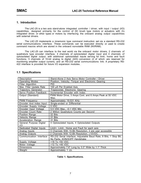
1.1 Specifications<br />
Description<br />
Operating Modes<br />
Filter Algorithm<br />
Max. Filter Update Rate<br />
Trajectory Generator<br />
Servo Position Feedback<br />
Output (Standard)<br />
PWM Frequency<br />
Encoder And Index Input<br />
Encoder Supply Voltage<br />
Encoder Input Voltage<br />
Encoder Count Rate<br />
Position Range<br />
Velocity Range<br />
Acceleration Range<br />
General Purpose Digital<br />
I/O<br />
Dedicated Digital Inputs<br />
Analog Inputs<br />
Analog Outputs<br />
Communication Interface<br />
Supply Voltage<br />
Motor Voltage<br />
Dimensions<br />
Weight<br />
Stand-Alone 2 Axis Servo Motor Controller / Driver<br />
Position, Velocity, Torque and Electronic Gearing<br />
PID<br />
100 µS Per Enabled Axis<br />
Trapezoidal, Electronic Gearing<br />
Incremental Encoder with Index<br />
PWM Motor Drive, 3 Amps Cont. and 6 Amps Peak at 50 VDC<br />
Max.<br />
Approximately 19.531 KHz<br />
Single-ended or Differential<br />
5 VDC<br />
5.5 VDC Max., -0.1 VDC Min.<br />
2 Million Quadrature Counts per Second<br />
32 Bits<br />
31 Bits<br />
31 Bits<br />
4 Optoisolated Inputs, 4 Optoisolated Outputs<br />
Limit+, Limit-, Home and Fault for each <strong>axis</strong><br />
5 Channels With 10-Bit Resolution, 3 are user accessible<br />
2 Channels With 12-Bit Resolution, ±10VDC.<br />
RS-232 Serial Interface, Adjustable Baud Rate, 8 Bits, 1 Stop Bit,<br />
No Parity, XON/XOFF Handshake<br />
+18 To +50 VDC<br />
+12 To +48 VDC<br />
Approximately 7.6Ó Long by 3.3Ó Wide by 1.1Ó Thick<br />
Approximately 1 Lb.<br />
Table 1. Specifications.<br />
7