
You also want an ePaper? Increase the reach of your titles
YUMPU automatically turns print PDFs into web optimized ePapers that Google loves.
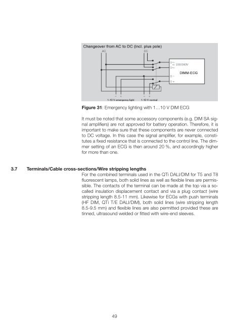
Figure 31: Emergency lighting with 1…10 V DIM ECG<br />
It must be noted that some accessory components (e.g. DIM SA signal<br />
amplifiers) are not approved for battery operation. Therefore, it is<br />
important to make sure that these components are never connected<br />
to DC voltage. In this case the signal amplifier, for example, constitutes<br />
a fixed resistance that is connected to the control line. The dimmer<br />
setting of an ECG is then around 20 %, and accordingly higher<br />
for more than one.<br />
3.7 Terminals/Cable cross-sections/Wire stripping lengths<br />
For the combined terminals used in the QTi <strong>DALI</strong>/DIM for T5 and T8<br />
fluorescent lamps, both solid lines as well as flexible lines are permissible.<br />
The contacts of the terminal can be made at the top via a socalled<br />
insulation displacement contact and via a plug contact (wire<br />
stripping length 8.5-11 mm). Likewise for ECGs with push terminals<br />
(HF DIM, QTi T/E <strong>DALI</strong>/DIM), both solid lines (wire stripping length<br />
8.5-9.5 mm) and flexible lines are also permitted provided these are<br />
tinned, ultrasound welded or fitted with wire-end sleeves.<br />
49