

T2 Ankle Arthrodesis Nail - Stryker
T2 Ankle Arthrodesis Nail - Stryker
T2 Ankle Arthrodesis Nail - Stryker

Create successful ePaper yourself
Turn your PDF publications into a flip-book with our unique Google optimized e-Paper software.
Operative Technique<br />
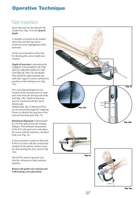
<strong>Nail</strong> Insertion<br />
Insert the nail over the Smooth Tip<br />
Guide Wire (Fig. 13) to the desired<br />
depth.<br />
A chamfer is located on the medial<br />
side of the nail driving end to<br />
avoid soft tissue impingement after<br />
insertion.<br />
Verify correct position of the nail<br />
by checking the correct depth and<br />
rotation.<br />
Depth of insertion is determined by<br />
CORRECT PLACEMENT OF THE<br />
DISTAL OBLONG HOLE IN THE<br />
CENTER OF THE TALAR BODY.<br />
This should be approximately the<br />
mid-talar region to ensure satisfactory<br />
purchase of the locking screw (Fig.<br />
13a).<br />
Two circumferential grooves are<br />
located on the insertion post at 2mm<br />
and 7mm from the driving end of the<br />
nail (Fig. 13b). Depth of insertion<br />
may be visualized with the aid of<br />
fluoroscopy.<br />
Additionally, the 3×285mm K-Wire<br />
can be inserted through the Targeting<br />
Device to identify the junction of the<br />
nail and insertion post (Fig. 13).<br />
Fig 13a<br />
2mm<br />
7mm<br />
Fig 13<br />
Rotational alignment is determined<br />
by a K-Wire placed into the Aiming<br />
Adapter. This indicates the position<br />
of the P/A calcaneal screw and aligns<br />
the screw with the anatomic calcaneal<br />
body axis (Fig. 14).<br />
Fig 13b<br />
Correct position is achieved when the<br />
K-Wire is in line with the vertical line<br />
marked on the plantar surface (used<br />
for determining the entry point) (Fig.<br />
14a).<br />
The K-Wire may be inserted 1cm<br />
into the calcaneus to help maintain<br />
position.<br />
Fig 14<br />
Remove the guide wire and proceed<br />
with locking screw placement.<br />
Fig 14a<br />
13


