Simatic - Programming with STEP7 - Process Control and ...
Simatic - Programming with STEP7 - Process Control and ...
Simatic - Programming with STEP7 - Process Control and ...

Create successful ePaper yourself
Turn your PDF publications into a flip-book with our unique Google optimized e-Paper software.
s<br />
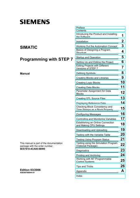
SIMATIC<br />
<strong>Programming</strong> <strong>with</strong> STEP 7<br />
Manual<br />
This manual is part of the documentation<br />
package <strong>with</strong> the order number:<br />
6ES7810-4CA08-8BW0<br />
Edition 03/2006<br />
A5E00706944-01<br />
Preface<br />
Contents<br />
Introducing the Product <strong>and</strong> Installing<br />
the Software 1<br />
Installation 2<br />
Working Out the Automation Concept 3<br />
Basics of Designing a Program<br />
Structure 4<br />
Startup <strong>and</strong> Operation 5<br />
Setting Up <strong>and</strong> Editing the Project 6<br />
Editing Projects <strong>with</strong> Different<br />
Versions of STEP 7 7<br />
Defining Symbols 8<br />
Creating Blocks <strong>and</strong> Libraries 9<br />
Creating Logic Blocks 10<br />
Creating Data Blocks 11<br />
Parameter Assignment for Data<br />
Blocks 12<br />
Creating STL Source Files 13<br />
Displaying Reference Data 14<br />
Checking Block Consistency <strong>and</strong><br />
Time Stamps as a Block Property 15<br />
Configuring Messages 16<br />
<strong>Control</strong>ling <strong>and</strong> Monitoring Variables 17<br />
Establishing an Online Connection<br />
<strong>and</strong> Making CPU Settings 18<br />
Downloading <strong>and</strong> Uploading 19<br />
Testing <strong>with</strong> the Variable Table 20<br />
Testing Using Program Status 21<br />
Testing using the Simulation Program<br />
(Optional Package) 22<br />
Diagnostics 23<br />
Printing <strong>and</strong> Archiving 24<br />
Working <strong>with</strong> M7 Programmable<br />
<strong>Control</strong> Systems 25<br />
Tips <strong>and</strong> Tricks 26<br />
Appendix<br />
Index<br />
A
Safety Guidelines<br />
This manual contains notices you have to observe in order to ensure your personal safety, as well as to<br />
prevent damage to property. The notices referring to your personal safety are highlighted in the manual<br />
by a safety alert symbol, notices referring to property damage only have no safety alert symbol. The<br />
notices shown below are graded according to the degree of danger.<br />
!<br />
!<br />
!<br />
Danger<br />
indicates that death or severe personal injury will result if proper precautions are not taken.<br />
Warning<br />
indicates that death or severe personal injury may result if proper precautions are not taken.<br />
Caution<br />
<strong>with</strong> a safety alert symbol indicates that minor personal injury can result if proper precautions are not<br />
taken.<br />
Caution<br />
<strong>with</strong>out a safety alert symbol indicates that property damage can result if proper precautions are not<br />
taken.<br />
Qualified Personnel<br />
Prescribed Usage<br />
Notice<br />
indicates that an unintended result or situation can occur if the corresponding notice is not taken into<br />
account.<br />
If more than one degree of danger is present, the warning notice representing the highest degree of<br />
danger will be used. A notice warning of injury to persons <strong>with</strong> a safety alert symbol may also include a<br />
warning relating to property damage.<br />
The device/system may only be set up <strong>and</strong> used in conjunction <strong>with</strong> this documentation. Commissioning<br />
<strong>and</strong> operation of a device/system may only be performed by qualified personnel. Within the context of<br />
the safety notices in this documentation qualified persons are defined as persons who are authorized to<br />
commission, ground <strong>and</strong> label devices, systems <strong>and</strong> circuits in accordance <strong>with</strong> established safety<br />
practices <strong>and</strong> st<strong>and</strong>ards.<br />
Note the following:<br />
!<br />
Warning<br />
This device <strong>and</strong> its components may only be used for the applications described in the catalog or the<br />
technical description, <strong>and</strong> only in connection <strong>with</strong> devices or components from other manufacturers<br />
which have been approved or recommended by Siemens.<br />
Correct, reliable operation of the product requires proper transport, storage, positioning <strong>and</strong> assembly<br />
as well as careful operation <strong>and</strong> maintenance.<br />
Trademarks<br />
All names identified by ® are registered trademarks of the Siemens AG.<br />
The remaining trademarks in this publication may be trademarks whose use by third parties for their<br />
own purposes could violate the rights of the owner.<br />
Disclaimer of Liability<br />
We have reviewed the contents of this publication to ensure consistency <strong>with</strong> the hardware <strong>and</strong><br />
software described. Since variance cannot be precluded entirely, we cannot guarantee full consistency.<br />
However, the information in this publication is reviewed regularly <strong>and</strong> any necessary corrections are<br />
included in subsequent editions.<br />
Siemens AG<br />
Automation <strong>and</strong> Drives<br />
Postfach 4848<br />
90437 NÜRNBERG<br />
GERMANY<br />
A5E00706944-01<br />
03/2006<br />
Copyright © Siemens AG 2006<br />
Technical data subject to change
Preface<br />
Purpose<br />
This manual provides a complete overview of programming <strong>with</strong> STEP 7. It is<br />
designed to support you when installing <strong>and</strong> commissioning the software. It<br />
explains how to proceed when creating programs <strong>and</strong> describes the components of<br />
user programs.<br />
The manual is intended for people who are involved in carrying out control tasks<br />
using STEP 7 <strong>and</strong> SIMATIC S7 automation systems.<br />
We recommend that you familiarize yourself <strong>with</strong> the examples in the manual<br />
"Working <strong>with</strong> STEP 7 V5.4, Getting Started." These examples provide an easy<br />
introduction to the topic "<strong>Programming</strong> <strong>with</strong> STEP 7."<br />
Basic Knowledge Required<br />
In order to underst<strong>and</strong> this manual, general knowledge of automation technology is<br />
required.<br />
In addition, you must be familiar <strong>with</strong> using computers or PC-similar tools (for<br />
example, programming devices) <strong>with</strong> the MS Windows 2000 Professional,<br />
MS Windows XP Professional or MS Windows Server 2003 operating system.<br />
Scope of the Manual<br />
This manual is valid for release 5.4 of the STEP 7 programming software package.<br />
You can find the latest information on the service packs:<br />
• in the "readme.wri" file<br />
• in the updated STEP 7 online help.<br />
The topic "What's new?" in the online help offers an excellent introduction <strong>and</strong><br />
overview of the newest STEP 7 innovations.<br />
<strong>Programming</strong> <strong>with</strong> STEP 7<br />
A5E00706944-01<br />
iii
Preface<br />
STEP 7 Documentation Packages<br />
This manual is part of the documentation package "STEP 7 Basic Information.“<br />
The following table displays an overview of the STEP 7 documentation:<br />
Documentation Purpose Order Number<br />
STEP 7 Basic Information <strong>with</strong><br />
Basic information for technical 6ES7810-4CA08-8BW0<br />
• Working <strong>with</strong> STEP 7,<br />
personnel describing the methods<br />
Getting Started Manual<br />
of implementing control tasks <strong>with</strong><br />
STEP 7 <strong>and</strong> the S7-300/400<br />
• <strong>Programming</strong> <strong>with</strong> STEP 7<br />
programmable controllers.<br />
• Configuring Hardware <strong>and</strong><br />
Communication Connections,<br />
STEP 7<br />
• From S5 to S7, Converter Manual<br />
STEP 7 Reference <strong>with</strong><br />
• Ladder Logic (LAD) / Function Block<br />
Diagram (FDB) / Statement List (STL)<br />
for S7-300/400 manuals<br />
• St<strong>and</strong>ard <strong>and</strong> System Function<br />
for S7-300/400<br />
Volume 1 <strong>and</strong> Volume 2<br />
Provides reference information<br />
<strong>and</strong> describes the programming<br />
languages LAD, FBD <strong>and</strong> STL,<br />
<strong>and</strong> st<strong>and</strong>ard <strong>and</strong> system function<br />
extending the scope of the<br />
STEP 7 basic information.<br />
6ES7810-4CA08-8BW1<br />
Online Helps Purpose Order Number<br />
Help on STEP 7<br />
Basic information on<br />
programming <strong>and</strong> configuring<br />
hardware <strong>with</strong> STEP 7 in the form<br />
of an online help.<br />
Part of the STEP 7<br />
St<strong>and</strong>ard software.<br />
Reference helps on AWL/KOP/FUP<br />
Reference help on SFBs/SFCs<br />
Reference help on Organization Blocks<br />
Context-sensitive reference<br />
information.<br />
Part of the STEP 7<br />
St<strong>and</strong>ard software.<br />
iv<br />
<strong>Programming</strong> <strong>with</strong> STEP 7<br />
A5E00706944-01
Preface<br />
Further Support<br />
If you have any technical questions, please get in touch <strong>with</strong> your Siemens<br />
representative or responsible agent.<br />
You will find your contact person at:<br />
http://www.siemens.com/automation/partner<br />
You will find a guide to the technical documentation offered for the individual<br />
SIMATIC Products <strong>and</strong> Systems here at:<br />
http://www.siemens.com/simatic-tech-doku-portal<br />
The online catalog <strong>and</strong> order system is found under:<br />
http://mall.automation.siemens.com/<br />
Training Centers<br />
Siemens offers a number of training courses to familiarize you <strong>with</strong> the SIMATIC<br />
S7 automation system. Please contact your regional training center or our central<br />
training center in D 90327 Nuremberg, Germany for details:<br />
Telephone: +49 (911) 895-3200.<br />
Internet: http://www.sitrain.com<br />
Technical Support<br />
You can reach the Technical Support for all A&D products<br />
• Via the Web formula for the Support Request<br />
http://www.siemens.com/automation/support-request<br />
• Phone: + 49 180 5050 222<br />
• Fax: + 49 180 5050 223<br />
Additional information about our Technical Support can be found on the Internet<br />
pages http://www.siemens.com/automation/service<br />
Service & Support on the Internet<br />
In addition to our documentation, we offer our Know-how online on the internet at:<br />
http://www.siemens.com/automation/service&support<br />
where you will find the following:<br />
• The newsletter, which constantly provides you <strong>with</strong> up-to-date information on<br />
your products.<br />
• The right documents via our Search function in Service & Support.<br />
• A forum, where users <strong>and</strong> experts from all over the world exchange their<br />
experiences.<br />
• Your local representative for Automation & Drives.<br />
• Information on field service, repairs, spare parts <strong>and</strong> more under "Services".<br />
<strong>Programming</strong> <strong>with</strong> STEP 7<br />
A5E00706944-01<br />
v
Preface<br />
vi<br />
<strong>Programming</strong> <strong>with</strong> STEP 7<br />
A5E00706944-01
Contents<br />
1 Introducing the Product <strong>and</strong> Installing the Software 1-1<br />
1.1 Overview of STEP 7 ......................................................................................... 1-1<br />
1.2 The STEP 7 St<strong>and</strong>ard Package ....................................................................... 1-6<br />
1.3 What's New in STEP 7, Version 5.4? ............................................................. 1-11<br />
1.4 Extended Uses of the STEP 7 St<strong>and</strong>ard Package ......................................... 1-14<br />
1.4.1 Engineering Tools........................................................................................... 1-15<br />
1.4.2 Run-Time Software......................................................................................... 1-17<br />
1.4.3 Human Machine Interface............................................................................... 1-19<br />
2 Installation 2-1<br />
2.1 Automation License Manager........................................................................... 2-1<br />
2.1.1 User Rights Through The Automation License Manager ................................. 2-1<br />
2.1.2 Installing the Automation License Manager...................................................... 2-4<br />
2.1.3 Guidelines for H<strong>and</strong>ling License Keys.............................................................. 2-5<br />
2.2 Installing STEP 7 .............................................................................................. 2-6<br />
2.2.1 Installation Procedure....................................................................................... 2-8<br />
2.2.2 Setting the PG/PC Interface ........................................................................... 2-11<br />
2.3 Uninstalling STEP 7........................................................................................ 2-13<br />
3 Working Out the Automation Concept 3-1<br />
3.1 Basic Procedure for Planning an Automation Project ...................................... 3-1<br />
3.2 Dividing the <strong>Process</strong> into Tasks <strong>and</strong> Areas...................................................... 3-2<br />
3.3 Describing the Individual Functional Areas ...................................................... 3-4<br />
3.4 Listing Inputs, Outputs, <strong>and</strong> In/Outs ................................................................. 3-6<br />
3.5 Creating an I/O Diagram for the Motors ........................................................... 3-6<br />
3.6 Creating an I/O Diagram for the Valves............................................................ 3-7<br />
3.7 Establishing the Safety Requirements.............................................................. 3-8<br />
3.8 Describing the Required Operator Displays <strong>and</strong> <strong>Control</strong>s................................ 3-9<br />
3.9 Creating a Configuration Diagram .................................................................. 3-10<br />
4 Basics of Designing a Program Structure 4-1<br />
4.1 Programs in a CPU........................................................................................... 4-1<br />
4.2 Blocks in the User Program.............................................................................. 4-2<br />
4.2.1 Organization Blocks <strong>and</strong> Program Structure .................................................... 4-3<br />
4.2.2 Call Hierarchy in the User Program.................................................................. 4-9<br />
4.2.3 Block Types .................................................................................................... 4-11<br />
4.2.3.1 Organization Block for Cyclic Program <strong>Process</strong>ing (OB1) ............................. 4-11<br />
4.2.3.2 Functions (FC) ................................................................................................ 4-16<br />
4.2.3.3 Function Blocks (FB) ...................................................................................... 4-17<br />
4.2.3.4 Instance Data Blocks...................................................................................... 4-20<br />
4.2.3.5 Shared Data Blocks (DB)................................................................................ 4-23<br />
4.2.3.6 System Function Blocks (SFB) <strong>and</strong> System Functions (SFC) ....................... 4-24<br />
<strong>Programming</strong> <strong>with</strong> STEP 7<br />
A5E00706944-01<br />
vii
Contents<br />
4.2.4 Organization Blocks for Interrupt-Driven Program <strong>Process</strong>ing....................... 4-26<br />
4.2.4.1 Time-of-Day Interrupt Organization Blocks (OB10 to OB17) ......................... 4-26<br />
4.2.4.2 Time-Delay Interrupt Organization Blocks (OB20 to OB23)........................... 4-28<br />
4.2.4.3 Cyclic Interrupt Organization Blocks (OB30 to OB38).................................... 4-29<br />
4.2.4.4 Hardware Interrupt Organization Blocks (OB40 to OB47).............................. 4-31<br />
4.2.4.5 Startup Organization Blocks (OB100 / OB101 / OB102)................................ 4-32<br />
4.2.4.6 Background Organization Block (OB90)......................................................... 4-34<br />
4.2.4.7 Error H<strong>and</strong>ling Organization Blocks (OB70 to OB87 / OB121 to OB122)...... 4-36<br />
5 Startup <strong>and</strong> Operation 5-1<br />
5.1 Starting STEP 7 ................................................................................................ 5-1<br />
5.2 Starting STEP 7 <strong>with</strong> Default Start Parameters................................................ 5-3<br />
5.3 Calling the Help Functions................................................................................ 5-5<br />
5.4 Objects <strong>and</strong> Object Hierarchy........................................................................... 5-6<br />
5.4.1 Project Object ................................................................................................... 5-8<br />
5.4.2 Library Object ................................................................................................... 5-9<br />
5.4.3 Station Object ................................................................................................. 5-10<br />
5.4.4 Programmable Module Object........................................................................ 5-12<br />
5.4.5 S7/M7 Program Object ................................................................................... 5-14<br />
5.4.6 Block Folder Object ........................................................................................ 5-16<br />
5.4.7 Source File Folder Object............................................................................... 5-19<br />
5.4.8 S7/M7 Program <strong>with</strong>out a Station or CPU...................................................... 5-20<br />
5.5 User Interface <strong>and</strong> Operation ......................................................................... 5-21<br />
5.5.1 Operating Philosophy ..................................................................................... 5-21<br />
5.5.2 Window Arrangement ..................................................................................... 5-22<br />
5.5.3 Elements in Dialog Boxes............................................................................... 5-23<br />
5.5.4 Creating <strong>and</strong> Managing Objects ..................................................................... 5-24<br />
5.5.5 Selecting Objects in a Dialog Box .................................................................. 5-29<br />
5.5.6 Session Memory ............................................................................................. 5-30<br />
5.5.7 Changing the Window Arrangement............................................................... 5-31<br />
5.5.8 Saving <strong>and</strong> Restoring the Window Arrangement ........................................... 5-31<br />
5.6 Keyboard Operation........................................................................................ 5-32<br />
5.6.1 Key Combinations for Menu Comm<strong>and</strong>s........................................................ 5-32<br />
5.6.2 Key Combinations for Moving the Cursor....................................................... 5-34<br />
5.6.3 Key Combinations for Selecting Text ............................................................. 5-36<br />
5.6.4 Key Combinations for Access to Online Help................................................. 5-36<br />
5.6.5 Key Combinations for Toggling between Windows ........................................ 5-37<br />
6 Setting Up <strong>and</strong> Editing the Project 6-1<br />
6.1 Project Structure ............................................................................................... 6-1<br />
6.2 What You Should Know About Access Protection ........................................... 6-2<br />
6.3 What You Should Know About The Change Log ............................................. 6-4<br />
6.4 Using Foreign-Language Character Sets......................................................... 6-5<br />
6.5 Setting the MS Windows Language ................................................................. 6-8<br />
6.6 Setting Up a Project.......................................................................................... 6-9<br />
6.6.1 Creating a Project............................................................................................. 6-9<br />
6.6.2 Inserting Stations ............................................................................................ 6-11<br />
6.6.3 Inserting an S7/M7 Program........................................................................... 6-12<br />
6.7 Editing a Project.............................................................................................. 6-14<br />
6.7.1 Checking Projects for Software Packages Used............................................ 6-15<br />
viii<br />
<strong>Programming</strong> <strong>with</strong> STEP 7<br />
A5E00706944-01
Contents<br />
6.8 Managing Multilingual Texts ........................................................................... 6-15<br />
6.8.1 Types of Multilingual Texts ............................................................................. 6-17<br />
6.8.2 Structure of the Export File............................................................................. 6-18<br />
6.8.3 Managing User Texts Whose Language Font is Not Installed ....................... 6-19<br />
6.8.4 Information on the Log File............................................................................. 6-20<br />
6.8.5 Optimizing the Source for Translation ............................................................ 6-21<br />
6.8.6 Optimizing the Translation <strong>Process</strong>................................................................ 6-22<br />
6.9 Micro Memory Card (MMC) as a Data Carrier................................................ 6-23<br />
6.9.1 What You Should Know About Micro Memory Cards (MMC)......................... 6-23<br />
6.9.2 Using a Micro Memory Card as a Data Carrier .............................................. 6-25<br />
6.9.3 Memory Card File ........................................................................................... 6-25<br />
6.9.4 Storing Project Data on a Micro Memory Card (MMC)................................... 6-26<br />
7 Editing Projects <strong>with</strong> Different Versions of STEP 7 7-1<br />
7.1 Editing Version 2 Projects <strong>and</strong> Libraries........................................................... 7-1<br />
7.2 Exp<strong>and</strong>ing DP Slaves That Were Created <strong>with</strong><br />
Previous Versions of STEP 7 ........................................................................... 7-1<br />
7.3 Editing Current Configurations <strong>with</strong> Previous Versions of STEP 7 .................. 7-3<br />
7.4 Appending SIMATIC PC Configurations of Previous Versions ........................ 7-4<br />
7.5 Displaying Modules Configured <strong>with</strong> Later STEP 7 Versions<br />
or Optional Packages ....................................................................................... 7-6<br />
8 Defining Symbols 8-1<br />
8.1 Absolute <strong>and</strong> Symbolic Addressing .................................................................. 8-1<br />
8.2 Shared <strong>and</strong> Local Symbols............................................................................... 8-3<br />
8.3 Displaying Shared or Local Symbols................................................................ 8-4<br />
8.4 Setting the Address Priority (Symbolic/Absolute)............................................. 8-5<br />
8.5 Symbol Table for Shared Symbols ................................................................... 8-9<br />
8.5.1 Structure <strong>and</strong> Components of the Symbol Table ............................................. 8-9<br />
8.5.2 Addresses <strong>and</strong> Data Types Permitted in the Symbol Table........................... 8-11<br />
8.5.3 Incomplete <strong>and</strong> Non-Unique Symbols in the Symbol Table........................... 8-12<br />
8.6 Entering Shared Symbols............................................................................... 8-13<br />
8.6.1 General Tips on Entering Symbols................................................................. 8-13<br />
8.6.2 Entering Single Shared Symbols in a Dialog Box .......................................... 8-14<br />
8.6.3 Entering Multiple Shared Symbols in the Symbol Table ................................ 8-15<br />
8.6.4 Using Upper <strong>and</strong> Lower Case for Symbols .................................................... 8-16<br />
8.6.5 Exporting <strong>and</strong> Importing Symbol Tables......................................................... 8-18<br />
8.6.6 File Formats for Importing/Exporting a Symbol Table .................................... 8-18<br />
8.6.7 Editing Areas in Symbol Tables...................................................................... 8-21<br />
9 Creating Blocks <strong>and</strong> Libraries 9-1<br />
9.1 Selecting an Editing Method............................................................................. 9-1<br />
9.2 Selecting the <strong>Programming</strong> Language ............................................................. 9-2<br />
9.2.1 Ladder Logic <strong>Programming</strong> Language (LAD)................................................... 9-4<br />
9.2.2 Function Block Diagram <strong>Programming</strong> Language (FBD)................................. 9-5<br />
9.2.3 Statement List <strong>Programming</strong> Language (STL)................................................. 9-6<br />
9.2.4 S7 SCL <strong>Programming</strong> Language...................................................................... 9-7<br />
9.2.5 S7-GRAPH <strong>Programming</strong> Language (Sequential <strong>Control</strong>) .............................. 9-8<br />
9.2.6 S7 HiGraph <strong>Programming</strong> Language (State Graph) ........................................ 9-9<br />
9.2.7 S7 CFC <strong>Programming</strong> Language ................................................................... 9-10<br />
9.3 Creating Blocks............................................................................................... 9-11<br />
9.3.1 Blocks Folder .................................................................................................. 9-11<br />
9.3.2 User-Defined Data Types (UDT) .................................................................... 9-12<br />
9.3.3 Block Properties.............................................................................................. 9-13<br />
9.3.4 Displaying Block Lengths................................................................................ 9-15<br />
9.3.5 Comparing Blocks........................................................................................... 9-16<br />
9.3.6 Rewiring.......................................................................................................... 9-19<br />
<strong>Programming</strong> <strong>with</strong> STEP 7<br />
A5E00706944-01<br />
ix
Contents<br />
9.3.7 Attributes for Blocks <strong>and</strong> Parameters ............................................................. 9-19<br />
9.4 Working <strong>with</strong> Libraries .................................................................................... 9-20<br />
9.4.1 Hierarchical Structure of Libraries .................................................................. 9-22<br />
9.4.2 Overview of the St<strong>and</strong>ard Libraries ................................................................ 9-22<br />
10 Creating Logic Blocks 10-1<br />
10.1 Basics of Creating Logic Blocks ..................................................................... 10-1<br />
10.1.1 Structure of the Program Editor Window........................................................ 10-1<br />
10.1.2 Basic Procedure for Creating Logic Blocks .................................................... 10-3<br />
10.1.3 Default Settings for the LAD/STL/FBD Program Editor.................................. 10-4<br />
10.1.4 Access Rights to Blocks <strong>and</strong> Source Files ..................................................... 10-4<br />
10.1.5 Instructions from the Program Elements Table .............................................. 10-5<br />
10.2 Editing the Variable Declaration ..................................................................... 10-6<br />
10.2.1 Using the Variable Declaration in Logic Blocks.............................................. 10-6<br />
10.2.2 Interaction Between The Variable Detail View And The Instruction List ........ 10-8<br />
10.2.3 Structure of the Variable Declaration Window................................................ 10-9<br />
10.3 Multiple Instances in the Variable Declaration ............................................. 10-10<br />
10.3.1 Using Multiple Instances............................................................................... 10-10<br />
10.3.2 Rules for Declaring Multiple Instances ......................................................... 10-11<br />
10.3.3 Entering a Multiple Instance in the Variable Declaration Window................ 10-11<br />
10.4 General Notes on Entering Statements <strong>and</strong> Comments .............................. 10-12<br />
10.4.1 Structure of the Code Section ...................................................................... 10-12<br />
10.4.2 Procedure for Entering Statements .............................................................. 10-13<br />
10.4.3 Entering Shared Symbols in a Program ....................................................... 10-14<br />
10.4.4 Title <strong>and</strong> Comments for Blocks <strong>and</strong> Networks ............................................. 10-15<br />
10.4.5 Entering Block Comments <strong>and</strong> Network Comments .................................... 10-16<br />
10.4.6 Working <strong>with</strong> Network Templates ................................................................. 10-17<br />
10.4.7 Search Function for Errors in the Code Section........................................... 10-18<br />
10.5 Editing LAD Elements in the Code Section .................................................. 10-19<br />
10.5.1 Settings for Ladder Logic <strong>Programming</strong>....................................................... 10-19<br />
10.5.2 Rules for Entering Ladder Logic Elements................................................... 10-19<br />
10.5.3 Illegal Logic Operations in Ladder ................................................................ 10-22<br />
10.6 Editing FBD Elements in the Code Section.................................................. 10-23<br />
10.6.1 Settings for Function Block Diagram <strong>Programming</strong> ..................................... 10-23<br />
10.6.2 Rules for Entering FBD Elements................................................................. 10-24<br />
10.7 Editing STL Statements in the Code Section ............................................... 10-26<br />
10.7.1 Settings for Statement List <strong>Programming</strong>..................................................... 10-26<br />
10.7.2 Rules for Entering STL Statements .............................................................. 10-26<br />
10.8 Updating Block Calls..................................................................................... 10-27<br />
10.8.1 Changing Interfaces...................................................................................... 10-28<br />
10.9 Saving Logic Blocks...................................................................................... 10-29<br />
11 Creating Data Blocks 11-1<br />
11.1 Basic Information on Creating Data Blocks.................................................... 11-1<br />
11.2 Declaration View of Data Blocks .................................................................... 11-2<br />
11.3 Data View of Data Blocks ............................................................................... 11-3<br />
11.4 Editing <strong>and</strong> Saving Data Blocks ..................................................................... 11-4<br />
11.4.1 Entering the Data Structure of Shared Data Blocks ....................................... 11-4<br />
11.4.2 Entering <strong>and</strong> Displaying the Data Structure<br />
of Data Blocks Referencing an FB (Instance DBs) ........................................ 11-5<br />
11.4.3 Entering the Data Structure of User-Defined Data Types (UDT) ................... 11-7<br />
11.4.4 Entering <strong>and</strong> Displaying the Structure of Data Blocks Referencing a UDT.... 11-8<br />
11.4.5 Editing Data Values in the Data View............................................................. 11-9<br />
11.4.6 Resetting Data Values to their Initial Values .................................................. 11-9<br />
11.4.7 Saving Data Blocks....................................................................................... 11-10<br />
x<br />
<strong>Programming</strong> <strong>with</strong> STEP 7<br />
A5E00706944-01
Contents<br />
12 Parameter Assignment for Data Blocks 12-1<br />
12.1 Assigning Parameters to Technological Functions ........................................ 12-2<br />
13 Creating STL Source Files 13-1<br />
13.1 Basic Information on <strong>Programming</strong> in STL Source Files................................ 13-1<br />
13.2 Rules for <strong>Programming</strong> in STL Source Files .................................................. 13-2<br />
13.2.1 Rules for Entering Statements in STL Source Files ....................................... 13-2<br />
13.2.2 Rules for Declaring Variables in STL Source Files ........................................ 13-3<br />
13.2.3 Rules for Block Order in STL Source Files..................................................... 13-4<br />
13.2.4 Rules for Setting System Attributes in STL Source Files ............................... 13-4<br />
13.2.5 Rules for Setting Block Properties in STL Source Files ................................. 13-5<br />
13.2.6 Permitted Block Properties for Each Block Type............................................ 13-7<br />
13.3 Structure of Blocks in STL Source Files......................................................... 13-7<br />
13.3.1 Structure of Logic Blocks in STL Source Files ............................................... 13-8<br />
13.3.2 Structure of Data Blocks in STL Source Files ................................................ 13-9<br />
13.3.3 Structure of User-Defined Data Types in STL Source Files........................... 13-9<br />
13.4 Syntax <strong>and</strong> Formats for Blocks in STL Source Files .................................... 13-10<br />
13.4.1 Format Table of Organization Blocks ........................................................... 13-10<br />
13.4.2 Format Table of Function Blocks.................................................................. 13-11<br />
13.4.3 Format Table of Functions............................................................................ 13-12<br />
13.4.4 Format Table of Data Blocks ........................................................................ 13-13<br />
13.5 Creating STL Source Files ........................................................................... 13-14<br />
13.5.1 Creating STL Source Files ........................................................................... 13-14<br />
13.5.2 Editing S7 Source Files ................................................................................ 13-14<br />
13.5.3 Setting The Layout of Source Code Text ..................................................... 13-15<br />
13.5.4 Inserting Block Templates in STL Source Files............................................ 13-15<br />
13.5.5 Inserting the Contents of Other STL Source Files........................................ 13-15<br />
13.5.6 Inserting Source Code from Existing Blocks in STL Source Files................ 13-16<br />
13.5.7 Inserting External Source Files..................................................................... 13-16<br />
13.5.8 Generating STL Source Files from Blocks ................................................... 13-17<br />
13.5.9 Importing Source Files.................................................................................. 13-17<br />
13.5.10 Exporting Source Files.................................................................................. 13-18<br />
13.6 Saving <strong>and</strong> Compiling STL Source Files <strong>and</strong> Executing<br />
a Consistency Check.................................................................................... 13-19<br />
13.6.1 Saving STL Source Files .............................................................................. 13-19<br />
13.6.2 Checking Consistency in STL Source Files.................................................. 13-19<br />
13.6.3 Debugging STL Source Files........................................................................ 13-19<br />
13.6.4 Compiling STL Source Files ......................................................................... 13-20<br />
13.7 Examples of STL Source Files ..................................................................... 13-21<br />
13.7.1 Examples of Declaring Variables in STL Source Files ................................. 13-21<br />
13.7.2 Example of Organization Blocks in STL Source Files .................................. 13-22<br />
13.7.3 Example of Functions in STL Source Files................................................... 13-23<br />
13.7.4 Example of Function Blocks in STL Source Files......................................... 13-25<br />
13.7.5 Example of Data Blocks in STL Source Files............................................... 13-27<br />
13.7.6 Example of User-Defined Data Types in STL Source Files ......................... 13-28<br />
14 Displaying Reference Data 14-1<br />
14.1 Overview of the Available Reference Data..................................................... 14-1<br />
14.1.1 Cross-Reference List...................................................................................... 14-2<br />
14.1.2 Program Structure .......................................................................................... 14-4<br />
14.1.3 Assignment List .............................................................................................. 14-6<br />
14.1.4 Unused Symbols............................................................................................. 14-8<br />
14.1.5 Addresses Without Symbols........................................................................... 14-9<br />
14.1.6 Displaying Block Information for LAD, FBD, <strong>and</strong> STL .................................... 14-9<br />
<strong>Programming</strong> <strong>with</strong> STEP 7<br />
A5E00706944-01<br />
xi
Contents<br />
14.2 Working <strong>with</strong> Reference Data....................................................................... 14-10<br />
14.2.1 Ways of Displaying Reference Data............................................................. 14-10<br />
14.2.2 Displaying Lists in Additional Working Windows .......................................... 14-10<br />
14.2.3 Generating <strong>and</strong> Displaying Reference Data................................................. 14-11<br />
14.2.4 Finding Address Locations in the Program Quickly...................................... 14-12<br />
14.2.5 Example of Working <strong>with</strong> Address Locations ............................................... 14-13<br />
15 Checking Block Consistency <strong>and</strong> Time Stamps as a Block Property 15-1<br />
15.1 Checking Block Consistency .......................................................................... 15-1<br />
15.2 Time Stamps as a Block Property <strong>and</strong> Time Stamp Conflicts........................ 15-3<br />
15.3 Time Stamps in Logic Blocks ......................................................................... 15-4<br />
15.4 Time Stamps in Shared Data Blocks.............................................................. 15-5<br />
15.5 Time Stamps in Instance Data Blocks............................................................ 15-5<br />
15.6 Time Stamps in UDTs <strong>and</strong> Data Blocks Derived from UDTs ......................... 15-6<br />
15.7 Correcting the Interfaces in a Function, Function Block, or UDT ................... 15-6<br />
15.8 Avoiding Errors when Calling Blocks.............................................................. 15-7<br />
16 Configuring Messages 16-1<br />
16.1 The Message Concept.................................................................................... 16-1<br />
16.1.1 What Are the Different Messaging Methods?................................................. 16-1<br />
16.1.2 Choosing a Messaging Method ...................................................................... 16-3<br />
16.1.3 SIMATIC Components.................................................................................... 16-5<br />
16.1.4 Parts of a Message......................................................................................... 16-5<br />
16.1.5 Which Message Blocks Are Available? .......................................................... 16-6<br />
16.1.6 Formal Parameters, System Attributes, <strong>and</strong> Message Blocks ....................... 16-8<br />
16.1.7 Message Type <strong>and</strong> Messages........................................................................ 16-9<br />
16.1.8 How to Generate an STL Source File from Message-Type Blocks.............. 16-10<br />
16.1.9 Assigning Message Numbers....................................................................... 16-10<br />
16.1.10 Differences Between Project-Oriented <strong>and</strong> CPU-Oriented Assignment of<br />
Message Numbers........................................................................................ 16-11<br />
16.1.11 Options for Modifying the Message Number Assignment of a Project......... 16-11<br />
16.2 Project-Oriented Message Configuration ..................................................... 16-12<br />
16.2.1 How to Assign Project-Oriented Message Numbers .................................... 16-12<br />
16.2.2 Assigning <strong>and</strong> Editing Block-Related Messages .......................................... 16-12<br />
16.2.2.1 How to Create Block-Related Messages (Project-Oriented)........................ 16-13<br />
16.2.2.2 How to Edit Block-Related Messages (Project-Oriented)............................. 16-16<br />
16.2.2.3 How to Configure PCS 7 Messages (Project-Oriented) ............................... 16-16<br />
16.2.3 Assigning <strong>and</strong> Editing Symbol-Related Messages....................................... 16-18<br />
16.2.3.1 How to Assign <strong>and</strong> Edit Symbol-Related Messages (Project-Oriented) ...... 16-18<br />
16.2.4 Creating <strong>and</strong> Editing User-Defined Diagnostic Messages ........................... 16-19<br />
16.3 CPU-Oriented Message Configuration......................................................... 16-20<br />
16.3.1 How to Assign CPU-Oriented Message Numbers........................................ 16-20<br />
16.3.2 Assigning <strong>and</strong> Editing Block-Related Messages .......................................... 16-21<br />
16.3.2.1 How to Create Block-Related Messages (CPU-Oriented)............................ 16-21<br />
16.3.2.2 How to Edit Block-Related Messages (CPU-Oriented) ................................ 16-24<br />
16.3.2.3 How to Configure PCS 7 Messages (CPU-Oriented)................................... 16-25<br />
16.3.3 Assigning <strong>and</strong> Editing Symbol-Related Messages....................................... 16-26<br />
16.3.3.1 How to Assign <strong>and</strong> Edit Symbol-Related Messages (CPU-Oriented) .......... 16-26<br />
16.3.4 Assigning <strong>and</strong> Editing User-Specific Diagnostic Messages ......................... 16-27<br />
16.4 Tips for Editing Messages ............................................................................ 16-28<br />
16.4.1 Adding Associated Values to Messages ...................................................... 16-28<br />
16.4.2 Integrating Texts from Text Libraries into Messages ................................... 16-30<br />
16.4.3 Deleting Associated Values.......................................................................... 16-31<br />
16.5 Translating <strong>and</strong> Editing Operator Related Texts .......................................... 16-32<br />
16.5.1 Translating <strong>and</strong> Editing User Texts .............................................................. 16-32<br />
xii<br />
<strong>Programming</strong> <strong>with</strong> STEP 7<br />
A5E00706944-01
Contents<br />
16.6 Translating <strong>and</strong> Editing Text Libraries .......................................................... 16-34<br />
16.6.1 User Text Libraries ....................................................................................... 16-34<br />
16.6.2 Creating User Text Libraries......................................................................... 16-34<br />
16.6.3 How to Edit User Text Libraries.................................................................... 16-35<br />
16.6.4 System Text Libraries................................................................................... 16-36<br />
16.6.5 Translating Text Libraries ............................................................................. 16-36<br />
16.7 Transferring Message Configuration Data to the Programmable <strong>Control</strong>ler 16-38<br />
16.8 Displaying CPU Messages <strong>and</strong> User-Defined Diagnostic Messages .......... 16-39<br />
16.8.1 Configuring CPU Messages ......................................................................... 16-42<br />
16.8.2 Displaying Stored CPU Messages ............................................................... 16-42<br />
16.9 Configuring the 'Reporting of System Errors' ............................................... 16-43<br />
16.9.1 Supported Components <strong>and</strong> Functional Scope............................................ 16-45<br />
16.9.2 Settings for "Report System Error" ............................................................... 16-48<br />
16.9.3 Generating Blocks for Reporting System Errors .......................................... 16-49<br />
16.9.4 Generated FB, DB ........................................................................................ 16-49<br />
16.9.5 Creating Foreign-Language Message Texts in 'Report System Error'......... 16-51<br />
17 <strong>Control</strong>ling <strong>and</strong> Monitoring Variables 17-1<br />
17.1 Configuring Variables for Operator <strong>Control</strong> <strong>and</strong> Monitoring ........................... 17-1<br />
17.2 Configuring Operator <strong>Control</strong> <strong>and</strong> Monitoring Attributes<br />
<strong>with</strong> Statement List, Ladder Logic, <strong>and</strong> Function Block Diagram................... 17-3<br />
17.3 Configuring Operator <strong>Control</strong> <strong>and</strong> Monitoring Attributes<br />
via the Symbol Table ...................................................................................... 17-4<br />
17.4 Changing Operator <strong>Control</strong> <strong>and</strong> Monitoring Attributes <strong>with</strong> CFC ................... 17-5<br />
17.5 Transferring Configuration Data to the<br />
Operator Interface Programmable <strong>Control</strong>ler ................................................. 17-6<br />
18 Establishing an Online Connection <strong>and</strong> Making CPU Settings 18-1<br />
18.1 Establishing Online Connections.................................................................... 18-1<br />
18.1.1 Establishing an Online Connection via the "Accessible Nodes" Window....... 18-2<br />
18.1.2 Establishing an Online Connection via the Online Window of the Project ..... 18-3<br />
18.1.3 Online Access to PLCs in a Multiproject......................................................... 18-4<br />
18.1.4 Password Protection for Access to Programmable <strong>Control</strong>lers...................... 18-6<br />
18.1.5 Updating the Window Contents ...................................................................... 18-7<br />
18.2 Displaying <strong>and</strong> Changing the Operating Mode............................................... 18-8<br />
18.2.1 Displaying <strong>and</strong> Changing the Operating Mode............................................... 18-8<br />
18.3 Displaying <strong>and</strong> Setting the Time <strong>and</strong> Date ..................................................... 18-9<br />
18.3.1 CPU Clocks <strong>with</strong> Time Zone Setting <strong>and</strong> Summer/Winter Time .................... 18-9<br />
18.4 Updating the Firmware ................................................................................. 18-10<br />
18.4.1 Updating Firmware in Modules <strong>and</strong> Submodules Online ............................. 18-10<br />
19 Downloading <strong>and</strong> Uploading 19-1<br />
19.1 Downloading from the PG/PC to the Programmable <strong>Control</strong>ler..................... 19-1<br />
19.1.1 Requirements for Downloading ...................................................................... 19-1<br />
19.1.2 Differences Between Saving <strong>and</strong> Downloading Blocks.................................. 19-2<br />
19.1.3 Load Memory <strong>and</strong> Work Memory in the CPU................................................. 19-3<br />
19.1.4 Download Methods Dependent on the Load Memory .................................... 19-4<br />
19.1.5 Downloading a Program to the S7 CPU......................................................... 19-5<br />
19.1.5.1 Downloading <strong>with</strong> Project Management ......................................................... 19-5<br />
19.1.5.2 Downloading <strong>with</strong>out Project Management .................................................... 19-6<br />
19.1.5.3 Reloading Blocks in the Programmable <strong>Control</strong>ler......................................... 19-6<br />
19.1.5.4 Saving Downloaded Blocks on Integrated EPROM ....................................... 19-7<br />
19.1.5.5 Downloading via EPROM Memory Cards ...................................................... 19-7<br />
19.2 Compiling <strong>and</strong> Downloading Several Objects from the PG............................ 19-9<br />
19.2.1 Requirements for <strong>and</strong> Notes on Downloading................................................ 19-9<br />
19.2.2 Compiling <strong>and</strong> Downloading Objects............................................................ 19-11<br />
<strong>Programming</strong> <strong>with</strong> STEP 7<br />
A5E00706944-01<br />
xiii
Contents<br />
19.3 Uploading from the Programmable <strong>Control</strong>ler to the PG/PC........................ 19-13<br />
19.3.1 Uploading a Station ...................................................................................... 19-14<br />
19.3.2 Uploading Blocks from an S7 CPU............................................................... 19-15<br />
19.3.3 Editing Uploaded Blocks in the PG/PC......................................................... 19-16<br />
19.3.3.1 Editing Uploaded Blocks if the User Program is on the PG/PC ................... 19-17<br />
19.3.3.2 Editing Uploaded Blocks if the User Program is Not on the PG/PC............. 19-17<br />
19.4 Deleting on the Programmable <strong>Control</strong>ler .................................................... 19-18<br />
19.4.1 Erasing the Load/Work Memory <strong>and</strong> Resetting the CPU ............................. 19-18<br />
19.4.2 Deleting S7 Blocks on the Programmable <strong>Control</strong>ler ................................... 19-19<br />
19.5 Compressing the User Memory (RAM) ........................................................ 19-20<br />
19.5.1 Gaps in the User Memory (RAM) ................................................................. 19-20<br />
19.5.2 Compressing the Memory Contents of an S7 CPU...................................... 19-21<br />
20 Testing <strong>with</strong> the Variable Table 20-1<br />
20.1 Introduction to Testing <strong>with</strong> Variable Tables .................................................. 20-1<br />
20.2 Basic Procedure when Monitoring <strong>and</strong> Modifying <strong>with</strong> the Variable Table .... 20-2<br />
20.3 Editing <strong>and</strong> Saving Variable Tables................................................................ 20-3<br />
20.3.1 Creating <strong>and</strong> Opening a Variable Table ......................................................... 20-3<br />
20.3.2 Copying/Moving Variable Tables.................................................................... 20-3<br />
20.3.3 Saving a Variable Table.................................................................................. 20-4<br />
20.4 Entering Variables in Variable Table .............................................................. 20-4<br />
20.4.1 Inserting Addresses or Symbols in a Variable Table...................................... 20-4<br />
20.4.2 Inserting a Contiguous Address Range in a Variable Table........................... 20-6<br />
20.4.3 Inserting Modify Values .................................................................................. 20-7<br />
20.4.4 Upper Limits for Entering Timers.................................................................... 20-7<br />
20.4.5 Upper Limits for Entering Counters ................................................................ 20-8<br />
20.4.6 Inserting Comment Lines................................................................................ 20-9<br />
20.4.7 Examples ........................................................................................................ 20-9<br />
20.5 Establishing a Connection to the CPU ......................................................... 20-13<br />
20.6 Monitoring Variables..................................................................................... 20-14<br />
20.6.1 Introduction to Monitoring Variables ............................................................. 20-14<br />
20.6.2 Defining the Trigger for Monitoring Variables............................................... 20-14<br />
20.7 Modifying Variables ...................................................................................... 20-16<br />
20.7.1 Introduction to Modifying Variables .............................................................. 20-16<br />
20.7.2 Defining the Trigger for Modifying Variables ................................................ 20-17<br />
20.8 Forcing Variables.......................................................................................... 20-19<br />
20.8.1 Safety Measures When Forcing Variables ................................................... 20-19<br />
20.8.2 Introduction to Forcing Variables.................................................................. 20-20<br />
20.8.3 Differences Between Forcing <strong>and</strong> Modifying Variables................................ 20-22<br />
21 Testing Using Program Status 21-1<br />
21.1 Program Status Display.................................................................................. 21-2<br />
21.2 What You Should Know About Testing in Single-Step Mode/Breakpoints..... 21-3<br />
21.3 What You Should Know About the HOLD Mode ............................................ 21-5<br />
21.4 Program Status of Data Blocks ...................................................................... 21-6<br />
21.5 Setting the Display for Program Status .......................................................... 21-7<br />
21.6 Setting the Mode for the Test ......................................................................... 21-8<br />
22 Testing using the Simulation Program (Optional Package) 22-1<br />
22.1 Testing using the Simulation Program S7-PLCSIM (Optional Package) ....... 22-1<br />
xiv<br />
<strong>Programming</strong> <strong>with</strong> STEP 7<br />
A5E00706944-01
Contents<br />
23 Diagnostics 23-1<br />
23.1 Hardware Diagnostics <strong>and</strong> Troubleshooting................................................... 23-1<br />
23.2 Diagnostics Symbols in the Online View ........................................................ 23-3<br />
23.3 Diagnosing Hardware: Quick View ................................................................. 23-5<br />
23.3.1 Calling the Quick View.................................................................................... 23-5<br />
23.3.2 Information Functions in the Quick View ........................................................ 23-5<br />
23.4 Diagnosing Hardware: Diagnostic View ......................................................... 23-6<br />
23.4.1 Calling the Diagnostic View ............................................................................ 23-6<br />
23.4.2 Information Functions in the Diagnostic View................................................. 23-8<br />
23.5 Module Information ......................................................................................... 23-9<br />
23.5.1 Options for Displaying the Module Information .............................................. 23-9<br />
23.5.2 Module Information Functions ...................................................................... 23-10<br />
23.5.3 Scope of the Module Type-Dependent Information...................................... 23-12<br />
23.5.4 Displaying the Module Status of PA Field Devices <strong>and</strong><br />
DP Slaves After a Y-Link .............................................................................. 23-13<br />
23.6 Diagnosing in STOP Mode ........................................................................... 23-15<br />
23.6.1 Basic Procedure for Determining the Cause of a STOP .............................. 23-15<br />
23.6.2 Stack Contents in STOP Mode..................................................................... 23-15<br />
23.7 Checking Scan Cycle Times to Avoid Time Errors....................................... 23-17<br />
23.8 Flow of Diagnostic Information ..................................................................... 23-18<br />
23.8.1 System Status List SSL ................................................................................ 23-19<br />
23.8.2 Sending Your Own Diagnostic Messages .................................................... 23-22<br />
23.8.3 Diagnostic Functions .................................................................................... 23-23<br />
23.9 Program Measures for H<strong>and</strong>ling Errors........................................................ 23-24<br />
23.9.1 Evaluating the Output Parameter RET_VAL ................................................ 23-25<br />
23.9.2 Error OBs as a Reaction to Detected Errors ................................................ 23-26<br />
23.9.3 Inserting Substitute Values for Error Detection ............................................ 23-31<br />
23.9.4 I/O Redundancy Error (OB70) ...................................................................... 23-33<br />
23.9.5 CPU Redundancy Error (OB72) ................................................................... 23-34<br />
23.9.6 Time Error (OB80) ........................................................................................ 23-35<br />
23.9.7 Power Supply Error (OB81).......................................................................... 23-36<br />
23.9.8 Diagnostic Interrupt (OB82).......................................................................... 23-37<br />
23.9.9 Insert/Remove Module Interrupt (OB83) ...................................................... 23-38<br />
23.9.10 CPU Hardware Fault (OB84)........................................................................ 23-39<br />
23.9.11 Program Sequence Error (OB85) ................................................................. 23-40<br />
23.9.12 Rack Failure (OB86)..................................................................................... 23-41<br />
23.9.13 Communication Error (OB87) ....................................................................... 23-42<br />
23.9.14 <strong>Programming</strong> Error (OB121) ........................................................................ 23-43<br />
23.9.15 I/O Access Error (OB122)............................................................................. 23-44<br />
24 Printing <strong>and</strong> Archiving 24-1<br />
24.1 Printing Project Documentation ...................................................................... 24-1<br />
24.1.1 Basic Procedure when Printing ...................................................................... 24-2<br />
24.1.2 Print Functions................................................................................................ 24-2<br />
24.1.3 Special Note on Printing the Object Tree ....................................................... 24-3<br />
24.2 Archiving Projects <strong>and</strong> Libraries ..................................................................... 24-4<br />
24.2.1 Uses for Saving/Archiving............................................................................... 24-5<br />
24.2.2 Requirements for Archiving ............................................................................ 24-5<br />
24.2.3 Procedure for Archiving/Retrieving................................................................. 24-6<br />
25 Working <strong>with</strong> M7 Programmable <strong>Control</strong> Systems 25-1<br />
25.1 Procedure for M7 Systems ............................................................................. 25-1<br />
25.2 Optional Software for M7 <strong>Programming</strong> ......................................................... 25-3<br />
25.3 M7-300/M7-400 Operating Systems............................................................... 25-6<br />
<strong>Programming</strong> <strong>with</strong> STEP 7<br />
A5E00706944-01<br />
xv
Contents<br />
26 Tips <strong>and</strong> Tricks 26-1<br />
26.1 Exchanging Modules in the Configuration Table............................................ 26-1<br />
26.2 Projects <strong>with</strong> a Large Number of Networked Stations.................................... 26-1<br />
26.3 Rearranging .................................................................................................... 26-2<br />
26.4 Editing Symbols Across Multiple Networks .................................................... 26-2<br />
26.5 Testing <strong>with</strong> the Variable Table ...................................................................... 26-3<br />
26.6 Modifying Variables With the Program Editor................................................. 26-4<br />
26.7 Virtual Work Memory ...................................................................................... 26-5<br />
A Appendix A-1<br />
A.1 Operating Modes ..............................................................................................A-1<br />
A.1.1 Operating Modes <strong>and</strong> Mode Transitions ..........................................................A-1<br />
A.1.2 STOP Mode ......................................................................................................A-4<br />
A.1.3 STARTUP Mode ...............................................................................................A-5<br />
A.1.4 RUN Mode ......................................................................................................A-13<br />
A.1.5 HOLD Mode....................................................................................................A-14<br />
A.2 Memory Areas of S7 CPUs.............................................................................A-15<br />
A.2.1 Distribution of the Memory Areas ...................................................................A-15<br />
A.2.2 Load Memory <strong>and</strong> Work Memory ...................................................................A-16<br />
A.2.3 System Memory..............................................................................................A-18<br />
A.2.3.1 Using the System Memory Areas ...................................................................A-18<br />
A.2.3.2 <strong>Process</strong>-Image Input/Output Tables...............................................................A-20<br />
A.2.3.3 Local Data Stack.............................................................................................A-24<br />
A.2.3.4 Interrupt Stack ................................................................................................A-25<br />
A.2.3.5 Block Stack .....................................................................................................A-26<br />
A.2.3.6 Diagnostic Buffer ............................................................................................A-27<br />
A.2.3.7 Evaluating the Diagnostic Buffer ....................................................................A-27<br />
A.2.3.8 Retentive Memory Areas on S7-300 CPUs....................................................A-29<br />
A.2.3.9 Retentive Memory Areas on S7-400 CPUs....................................................A-30<br />
A.2.3.10 Configurable Memory Objects in the Work Memory.......................................A-31<br />
A.3 Data Types <strong>and</strong> Parameter Types..................................................................A-32<br />
A.3.1 Introduction to Data Types <strong>and</strong> Parameter Types..........................................A-32<br />
A.3.2 Elementary Data Types ..................................................................................A-33<br />
A.3.2.1 Format of the Data Type INT (16-Bit Integers)...............................................A-34<br />
A.3.2.2 Format of the Data Type DINT (32-Bit Integers) ............................................A-34<br />
A.3.2.3 Format of the Data Type REAL (Floating-Point Numbers).............................A-35<br />
A.3.2.4 Format of the Data Types WORD <strong>and</strong> DWORD in<br />
Binary Coded Decimal Numbers ....................................................................A-39<br />
A.3.2.5 Format of the Data Type S5TIME (Time Duration) ........................................A-40<br />
A.3.3 Complex Data Types ......................................................................................A-41<br />
A.3.3.1 Format of the Data Type DATE_AND_TIME..................................................A-42<br />
A.3.3.2 Using Complex Data Types............................................................................A-44<br />
A.3.3.3 Using Arrays to Access Data..........................................................................A-45<br />
A.3.3.4 Using Structures to Access Data....................................................................A-48<br />
A.3.3.5 Using User-Defined Data Types to Access Data ...........................................A-50<br />
A.3.4 Parameter Types ............................................................................................A-52<br />
A.3.4.1 Format of the Parameter Types BLOCK, COUNTER, TIMER .......................A-53<br />
A.3.4.2 Format of the Parameter Type POINTER ......................................................A-53<br />
A.3.4.3 Using the Parameter Type POINTER.............................................................A-54<br />
A.3.4.4 Block for Changing the Pointer.......................................................................A-55<br />
A.3.4.5 Format of the Parameter Type ANY ...............................................................A-58<br />
A.3.4.6 Using the Parameter Type ANY .....................................................................A-61<br />
A.3.4.7 Assigning Data Types to Local Data of Logic Blocks .....................................A-64<br />
A.3.4.8 Permitted Data Types when Transferring Parameters ...................................A-66<br />
A.3.4.9 Transferring to IN_OUT Parameters of a Function Block...............................A-71<br />
xvi<br />
<strong>Programming</strong> <strong>with</strong> STEP 7<br />
A5E00706944-01
Contents<br />
Index<br />
A.4 Working <strong>with</strong> Older Projects ...........................................................................A-72<br />
A.4.1 Converting Version 1 Projects ........................................................................A-72<br />
A.4.2 Converting Version 2 Projects ........................................................................A-73<br />
A.4.3 Notes on STEP 7 V.2.1 Projects <strong>with</strong> GD Communication ............................A-74<br />
A.4.4 DP-Slaves <strong>with</strong> Missing or Faulty GSD Files..................................................A-74<br />
A.5 Sample Programs ...........................................................................................A-75<br />
A.5.1 Sample Projects <strong>and</strong> Sample Programs.........................................................A-75<br />
A.5.2 Sample Program for an Industrial Blending <strong>Process</strong>......................................A-77<br />
A.5.2.1 Defining Logic Blocks .....................................................................................A-79<br />
A.5.2.2 Assigning Symbolic Names ............................................................................A-81<br />
A.5.2.3 Creating the FB for the Motor .........................................................................A-83<br />
A.5.2.4 Creating the FC for the Valves .......................................................................A-88<br />
A.5.2.5 Creating OB1 ..................................................................................................A-90<br />
A.5.3 Example of H<strong>and</strong>ling Time-of-Day Interrupts .................................................A-96<br />
A.5.3.1 Structure of the User Program "Time-of-Day Interrupts"................................A-96<br />
A.5.3.2 FC12 ...............................................................................................................A-98<br />
A.5.3.3 OB10.............................................................................................................A-100<br />
A.5.3.4 OB1 <strong>and</strong> OB80 .............................................................................................A-102<br />
A.5.4 Example of H<strong>and</strong>ling Time-Delay Interrupts.................................................A-104<br />
A.5.4.1 Structure of the User Program "Time-Delay Interrupts" ...............................A-104<br />
A.5.4.2 OB20.............................................................................................................A-106<br />
A.5.4.3 OB1...............................................................................................................A-108<br />
A.5.4.4 Example of Masking <strong>and</strong> Unmasking Synchronous Errors ..........................A-110<br />
A.5.4.5 Example of Disabling <strong>and</strong> Enabling Interrupts <strong>and</strong><br />
Asynchronous Errors (SFC39 <strong>and</strong> SFC40) ..................................................A-115<br />
A.5.4.6 Example of the Delayed <strong>Process</strong>ing of Interrupts <strong>and</strong><br />
Asynchronous Errors (SFC41 <strong>and</strong> SFC42) ..................................................A-116<br />
A.6 Accessing <strong>Process</strong> <strong>and</strong> I/O Data Areas .......................................................A-117<br />
A.6.1 Accessing the <strong>Process</strong> Data Area ................................................................A-117<br />
A.6.2 Accessing the Peripheral Data Area.............................................................A-118<br />
A.7 Setting the Operating Behavior ....................................................................A-120<br />
A.7.1 Changing the Behavior <strong>and</strong> Properties of Modules......................................A-121<br />
A.7.2 Updating the Firmware (of the Operating System) in<br />
Modules <strong>and</strong> Submodules Offline.................................................................A-124<br />
A.7.3 Using the Clock Functions............................................................................A-126<br />
A.7.4 Using Clock Memory <strong>and</strong> Timers .................................................................A-128<br />
Index-1<br />
<strong>Programming</strong> <strong>with</strong> STEP 7<br />
A5E00706944-01<br />
xvii
Contents<br />
xviii<br />
<strong>Programming</strong> <strong>with</strong> STEP 7<br />
A5E00706944-01
1 Introducing the Product <strong>and</strong> Installing the<br />
Software<br />
1.1 Overview of STEP 7<br />
What is STEP 7?<br />
STEP 7 is the st<strong>and</strong>ard software package used for configuring <strong>and</strong> programming<br />
SIMATIC programmable logic controllers. It is part of the SIMATIC industry<br />
software. There are the following versions of the STEP 7 St<strong>and</strong>ard package:<br />
• STEP 7 Micro/DOS <strong>and</strong> STEP 7 Micro/Win for simpler st<strong>and</strong>-alone applications<br />
on the SIMATIC S7-200.<br />
• STEP 7 for applications on SIMATIC S7-300/S7-400, SIMATIC M7-300/M7-400,<br />
<strong>and</strong> SIMATIC C7 <strong>with</strong> a wider range of functions:<br />
- Can be extended as an option by the software products in the SIMATIC<br />
Industry Software (see also Extended Uses of the STEP 7 St<strong>and</strong>ard<br />
Package)<br />
- Opportunity of assigning parameters to function modules <strong>and</strong><br />
communications processors<br />
- Forcing <strong>and</strong> multicomputing mode<br />
- Global data communication<br />
- Event-driven data transfer using communication function blocks<br />
- Configuring connections<br />
STEP 7 is the subject of this documentation, STEP 7 Micro is described in the<br />
"STEP 7 Micro/DOS" documentation.<br />
Basic Tasks<br />
When you create an automation solution <strong>with</strong> STEP 7, there are a series of basic<br />
tasks. The following figure shows the tasks that need to be performed for most<br />
projects <strong>and</strong> assigns them to a basic procedure. It refers you to the relevant<br />
chapter thus giving you the opportunity of moving through the manual to find taskrelated<br />
information.<br />
<strong>Programming</strong> <strong>with</strong> STEP 7<br />
A5E00706944-01 1-1
Introducing the Product <strong>and</strong> Installing the Software<br />
<br />
<br />
<br />
<br />
<br />
<br />
<br />
<br />
<br />
<br />
<br />
<br />
<br />
<br />
<br />
<br />
<br />
<br />
<br />
<br />
<br />
<br />
<br />
<br />
<br />
<br />
<br />
<br />
<br />
<br />
<br />
<br />
<br />
<br />
<br />
<br />
<br />
<br />
<br />
<br />
<br />
<strong>Programming</strong> <strong>with</strong> STEP 7<br />
1-2 A5E00706944-01
Introducing the Product <strong>and</strong> Installing the Software<br />
Alternative Procedures<br />
As shown in the figure above, you have two alternative procedures:<br />
• You can configure the hardware first <strong>and</strong> then program the blocks.<br />
• You can, however, program the blocks first <strong>with</strong>out configuring the hardware.<br />
This is recommended for service <strong>and</strong> maintenance work, for example, to<br />
integrate programmed blocks into in an existing project.<br />
Brief Description of the Individual Steps<br />
• Install STEP 7 <strong>and</strong> license keys<br />
The first time you use STEP 7, install it <strong>and</strong> transfer the license keys from<br />
diskette to the hard disk (see also Installing STEP 7 <strong>and</strong> Authorization).<br />
• Plan your controller<br />
Before you work <strong>with</strong> STEP 7, plan your automation solution from dividing the<br />
process into individual tasks to creating a configuration diagram (see also Basic<br />
Procedure for Planning an Automation Project).<br />
• Design the program structure<br />
Turn the tasks described in the draft of your controller design into a program<br />
structure using the blocks available in STEP 7 (see also Blocks in the User<br />
Program).<br />
• Start STEP 7<br />
You start STEP 7 from the Windows user interface (see also Starting STEP 7).<br />
• Create a project structure<br />
A project is like a folder in which all data are stored in a hierarchical structure<br />
<strong>and</strong> are available to you at any time. After you have created a project, all other<br />
tasks are executed in this project (see also Project Structure).<br />
• Configure a station<br />
When you configure the station you specify the programmable controller you<br />
want to use; for example, SIMATIC 300, SIMATIC 400, SIMATIC S5 (see also<br />
Inserting Stations).<br />
• Configure hardware<br />
When you configure the hardware you specify in a configuration table which<br />
modules you want to use for your automation solution <strong>and</strong> which addresses are<br />
to be used to access the modules from the user program. The properties of the<br />
modules can also be assigned using parameters (see also Basic Procedure for<br />
Configuring Hardware) .<br />
• Configure networks <strong>and</strong> communication connections<br />
The basis for communication is a pre-configured network. For this, you will need<br />
to create the subnets required for your automation networks, set the subnet<br />
properties, <strong>and</strong> set the network connection properties <strong>and</strong> any communication<br />
connections required for the networked stations (see also Procedure for<br />
Configuring a Subnet).<br />
• Define symbols<br />
You can define local or shared symbols, which have more descriptive names, in<br />
a symbol table to use instead of absolute addresses in your user program (see<br />
also Creating a Symbol Table).<br />
<strong>Programming</strong> <strong>with</strong> STEP 7<br />
A5E00706944-01 1-3
Introducing the Product <strong>and</strong> Installing the Software<br />
• Create the program<br />
Using one of the available programming languages create a program linked to a<br />
module or independent of a module <strong>and</strong> store it as blocks, source files, or<br />
charts (see also Basic Procedure for Creating Logic Blocks <strong>and</strong> Basic<br />
Information on <strong>Programming</strong> in STL Source Files).<br />
• S7 only: generate <strong>and</strong> evaluate reference data<br />
You can make use of these reference data to make debugging <strong>and</strong> modifying<br />
your user program easier (see also Overview of the Available Reference Data).<br />
• Configure messages<br />
You create block-related messages, for example, <strong>with</strong> their texts <strong>and</strong> attributes.<br />
Using the transfer program you transfer the message configuration data created<br />
to the operator interface system database (for example, SIMATIC WinCC,<br />
SIMATIC ProTool), see also Configuring Messages.<br />
• Configure operator control <strong>and</strong> monitoring variables<br />
You create operator control <strong>and</strong> monitoring variables once in STEP 7 <strong>and</strong><br />
assign them the required attributes. Using the transfer program you transfer the<br />
operator control <strong>and</strong> monitoring variables created to the database of the<br />
operator interface system WinCC (see also Configuring Variables for Operator<br />
<strong>Control</strong> <strong>and</strong> Monitoring).<br />
• Download programs to the programmable controller<br />
S7 only: after all configuration, parameter assignment, <strong>and</strong> programming tasks<br />
are completed, you can download your entire user program or individual blocks<br />
from it to the programmable controller (programmable module for your hardware<br />
solution). (See also Requirements for Downloading.) The CPU already contains<br />
the operating system.<br />
M7 only: choose a suitable operating system for your automation solution from<br />
a number of different operating systems <strong>and</strong> transfer this on its own or together<br />
<strong>with</strong> the user program to the required data medium of the M7 programmable<br />
control system.<br />
• Test programs<br />
S7 only: for testing you can either display the values of variables from your user<br />
program or a CPU, assign values to the variables, <strong>and</strong> create a variable table<br />
for the variables that you want to display or modify (see also Introduction to<br />
Testing <strong>with</strong> the Variable Table).<br />
M7 only: test the user program <strong>with</strong> a high-level language-debugging tool.<br />
• Monitor operation, diagnose hardware<br />
You determine the cause of a module fault by displaying online information<br />
about a module. You determine the causes for errors in user program<br />
processing <strong>with</strong> the help of the diagnostic buffer <strong>and</strong> the stack contents. You<br />
can also check whether a user program can run on a particular CPU (see also<br />
Hardware Diagnostics <strong>and</strong> Displaying Module Information).<br />
• Document the plant<br />
After you have created a project/plant, it makes sense to produce clear<br />
documentation of the project data to make further editing of the project <strong>and</strong> any<br />
service activities easier (see also Printing Project Documentation). DOCPRO,<br />
the optional tool for creating <strong>and</strong> managing plant documentation, allows you to<br />
structure the project data, put it into wiring manual form, <strong>and</strong> print it out in a<br />
common format.<br />
<strong>Programming</strong> <strong>with</strong> STEP 7<br />
1-4 A5E00706944-01
Introducing the Product <strong>and</strong> Installing the Software<br />
Specialized Topics<br />
When you create an automation solution there are a number of special topics that<br />
may be of interest to you:<br />
• Multicomputing - Synchronous Operation of Several CPUs (see also<br />
Multicomputing - Synchronous Operation of Several CPUs)<br />
• More than One User Working in a Project (see also More than One User Editing<br />
Projects)<br />
• Working <strong>with</strong> M7 Systems (see also Procedure for M7 Systems)<br />
<strong>Programming</strong> <strong>with</strong> STEP 7<br />
A5E00706944-01 1-5
Introducing the Product <strong>and</strong> Installing the Software<br />
1.2 The STEP 7 St<strong>and</strong>ard Package<br />
St<strong>and</strong>ards Used<br />
The SIMATIC programming languages integrated in STEP 7 are compliant <strong>with</strong><br />
EN 61131-3. The st<strong>and</strong>ard package matches the graphic <strong>and</strong> object oriented<br />
operating philosophy of Windows <strong>and</strong> runs under the operating system<br />
MS Windows 2000 Professional (as of now referred to as Windows 2000) as well<br />
as MS Windows XP Professional (as of now referred to as Windows XP) <strong>and</strong><br />
MS Windows Server 2003.<br />
Functions of the st<strong>and</strong>ard package<br />
The st<strong>and</strong>ard software supports you in all phases of the creation process of an<br />
automation task, such as:<br />
• Setting up <strong>and</strong> managing projects<br />
• Configuring <strong>and</strong> assigning parameters to hardware <strong>and</strong> communications<br />
• Managing symbols<br />
• Creating programs, for example, for S7 programmable controllers<br />
• Downloading programs to programmable controllers<br />
• Testing the automation system<br />
• Diagnosing plant failures<br />
The STEP 7 software user interface has been designed to meet the latest<br />
state-of-the-art ergonomics <strong>and</strong> makes it easy for you to get started.<br />
The documentation for the STEP 7 software product provides all the information<br />
online in the online Help <strong>and</strong> in electronic manuals in PDF format.<br />
<strong>Programming</strong> <strong>with</strong> STEP 7<br />
1-6 A5E00706944-01
Introducing the Product <strong>and</strong> Installing the Software<br />
Applications in STEP 7<br />
The STEP 7 St<strong>and</strong>ard package provides a series of applications (tools) <strong>with</strong>in the<br />
software:<br />
<br />
<br />
<br />
<br />
<br />
<br />
<br />
<br />
<br />
<br />
<br />
<br />
You do not need to open the tools separately; they are started automatically when<br />
you select the corresponding function or open an object.<br />
<strong>Programming</strong> <strong>with</strong> STEP 7<br />
A5E00706944-01 1-7
Introducing the Product <strong>and</strong> Installing the Software<br />
SIMATIC Manager<br />
The SIMATIC Manager manages all the data that belong to an automation project<br />
− regardless of which programmable control system (S7/M7/C7) they are designed<br />
for. The tools needed to edit the selected data are started automatically by the<br />
SIMATIC Manager.<br />
Symbol Editor<br />
With the Symbol Editor you manage all the shared symbols. The following<br />
functions are available:<br />
• Setting symbolic names <strong>and</strong> comments for the process signals (inputs/outputs),<br />
bit memory, <strong>and</strong> blocks<br />
• Sort functions<br />
• Import/export to/from other Windows programs<br />
The symbol table created <strong>with</strong> this tool is available to all the other tools. Any<br />
changes to the properties of a symbol are therefore recognized automatically by all<br />
tools.<br />
<strong>Programming</strong> <strong>with</strong> STEP 7<br />
1-8 A5E00706944-01
Introducing the Product <strong>and</strong> Installing the Software<br />
Diagnosing Hardware<br />
These functions provide you <strong>with</strong> an overview of the status of the programmable<br />
controller. An overview can display symbols to show whether every module has a<br />
fault or not. A double-click on the faulty module displays detailed information about<br />
the fault. The scope of this information depends on the individual module:<br />
• Display general information about the module (for example, order number,<br />
version, name) <strong>and</strong> the status of the module (for example, faulty)<br />
• Display the module faults (for example, channel fault) for the central I/O <strong>and</strong> DP<br />
slaves<br />
• Display messages from the diagnostic buffer<br />
For CPUs the following additional information is displayed:<br />
• Causes of faults in the processing of a user program<br />
• Display the cycle duration (of the longest, shortest, <strong>and</strong> last cycle)<br />
• MPI communication possibilities <strong>and</strong> load<br />
• Display performance data (number of possible inputs/outputs, bit memory,<br />
counters, timers, <strong>and</strong> blocks)<br />
<strong>Programming</strong> Languages<br />
The programming languages Ladder Logic, Statement List, <strong>and</strong> Function Block<br />
Diagram for S7-300 <strong>and</strong> S7-400 are an integral part of the st<strong>and</strong>ard package.<br />
• Ladder Logic (or LAD) is a graphic representation of the STEP 7 programming<br />
language. Its syntax for the instructions is similar to a relay ladder logic<br />
diagram: Ladder allows you to track the power flow between power rails as it<br />
passes through various contacts, complex elements, <strong>and</strong> output coils.<br />
• Statement List (or STL) is a textual representation of the STEP 7 programming<br />
language, similar to machine code. If a program is written in Statement List, the<br />
individual instructions correspond to the steps <strong>with</strong> which the CPU executes the<br />
program. To make programming easier, Statement List has been extended to<br />
include some high-level language constructions (such as structured data access<br />
<strong>and</strong> block parameters).<br />
• Function Block Diagram (FBD) is a graphic representation of the STEP 7<br />
programming language <strong>and</strong> uses the logic boxes familiar from Boolean algebra<br />
to represent the logic. Complex functions (for example, math functions) can be<br />
represented directly in conjunction <strong>with</strong> the logic boxes.<br />
Other programming languages are available as optional packages.<br />
<strong>Programming</strong> <strong>with</strong> STEP 7<br />
A5E00706944-01 1-9
Introducing the Product <strong>and</strong> Installing the Software<br />
Hardware Configuration<br />
You use this tool to configure <strong>and</strong> assign parameters to the hardware of an<br />
automation project. The following functions are available:<br />
• To configure the programmable controller you select racks from an electronic<br />
catalog <strong>and</strong> arrange the selected modules in the required slots in the racks.<br />
• Configuring the distributed I/O is identical to the configuration of the central I/O.<br />
Channel-granular I/O is also supported.<br />
• In the course of assigning parameters to the CPU you can set properties such<br />
as startup behavior <strong>and</strong> scan cycle time monitoring guided by menus.<br />
Multicomputing is supported. The data entered are stored in system data<br />
blocks.<br />
• In the course of assigning parameters to the modules, all the parameters you<br />
can set are set using dialog boxes. There are no settings to be made using DIP<br />
switches. The assignment of parameters to the modules is done automatically<br />
during startup of the CPU. This means, for example, that a module can be<br />
exchanged <strong>with</strong>out assigning new parameters.<br />
• Assigning parameters to function modules (FMs) <strong>and</strong> communications<br />
processors (CPs) is also done <strong>with</strong>in the Hardware Configuration tool in exactly<br />
the same way as for the other modules. Module-specific dialog boxes <strong>and</strong> rules<br />
exist for every FM <strong>and</strong> CP (included in the scope of the FM/CP function<br />
package). The system prevents incorrect entries by only offering valid options in<br />
the dialog boxes.<br />
NetPro (Network Configuration)<br />
Using NetPro time-driven cyclic data transfer via the MPI is possible where you:<br />
• Select the communication nodes<br />
• Enter the data source <strong>and</strong> data target in a table; all blocks (SDBs) to be<br />
downloaded are generated automatically <strong>and</strong> completely downloaded to all<br />
CPUs automatically<br />
Event-driven data transfer is also possible where you:<br />
• Set the communication connections<br />
• Select the communication or function blocks from the integrated block library<br />
• Assign parameters to the selected communication or function blocks in your<br />
chosen programming language<br />
<strong>Programming</strong> <strong>with</strong> STEP 7<br />
1-10 A5E00706944-01
Introducing the Product <strong>and</strong> Installing the Software<br />
1.3 What's New in STEP 7, Version 5.4?<br />
The following subject areas have been updated:<br />
• SIMATIC Manager<br />
• Configuring <strong>and</strong> Diagnosing Hardware<br />
• Configuring Networks <strong>and</strong> Connections<br />
• St<strong>and</strong>ard Libraries<br />
• Report System Error<br />
SIMATIC Manager<br />
• As of STEP 7 V5.4, there are two formats available for displaying the date <strong>and</strong><br />
the time. You can select a display in the respective STEP 7 national language<br />
<strong>and</strong> or in ISO 8601 st<strong>and</strong>ard format. To make this setting, go to the SIMATIC<br />
Manager, open the "Customize" dialog box <strong>and</strong> select the "Date <strong>and</strong> Time" tab.<br />
• As of STEP 7 V5.4, you can have module times displayed in the local time for<br />
your programming device (PG)/PC. To make this setting, go to the SIMATIC<br />
Manager, open the "Customize" dialog box <strong>and</strong> select the "Date <strong>and</strong> Time" tab.<br />
• As of STEP 7 V5.4, you have the option of restricting access to projects <strong>and</strong><br />
libraries by assigning a passwords to them. In order to do this, you must have<br />
installed SIMATIC Logon V1.3 SP1 (as of now referred to as SIMATIC Logon)<br />
(see What You Should Know About Access).<br />
• As of STEP 7 V5.4, after setting up access protection for projects <strong>and</strong> libraries,<br />
you have the option of keeping a change log that records online actions such as<br />
"Download", "Operating Mode Changes", <strong>and</strong> "Reset". In order to do this, you<br />
must have installed SIMATIC Logon V1.3 SP1 (as of now referred to as<br />
SIMATIC Logon) (see What You Should Know About Access Protection).<br />
<strong>Programming</strong> <strong>with</strong> STEP 7<br />
A5E00706944-01 1-11
Introducing the Product <strong>and</strong> Installing the Software<br />
Configuring <strong>and</strong> Diagnosing Hardware<br />
• The "Information <strong>and</strong> Maintenance" process is supported in order to be able to<br />
read identification data from or write identification data to modules. This function<br />
is also available in the SIMATIC Manager (see Identification <strong>and</strong> Maintenance<br />
(I&M)).<br />
• Identification data can also be written to PROFIBUS DP interface modules<br />
during redundant mode (by means of "Accessible Nodes"). The interface<br />
module must support this function.<br />
• CAx data can be imported <strong>and</strong> exported. In this way, data can be exchanged<br />
between STEP 7 <strong>and</strong> CAD systems or CAE engineering systems (see<br />
Exporting <strong>and</strong> Importing CAx Data)<br />
• The firmware for PROFIBUS DP interface modules can also be updated during<br />
redundant mode, as long as such a module will support this process. Each of<br />
the redundantly used interface modules can now send the updated firmware<br />
through the active backplane bus to the other, redundant interface module.<br />
• The "Software Redundancy" function now allows PA links <strong>with</strong> subordinate PA<br />
slaves to be copied <strong>and</strong> redundantly inserted (see Configuring SW<br />
Redundancy)<br />
• Applications for editing objects in HW Config can now be started <strong>with</strong> the Edit ><br />
Open Object menu comm<strong>and</strong> (see Opening Objects in HW Config).<br />
• You can configure a watchdog time for PROFINET IO devices (see Configuring<br />
the Watchdog Time)<br />
• As of STEP 7 V5.4, you can have module times displayed in the local time of<br />
your programming device (PG)/PC.<br />
Configuring Networks <strong>and</strong> Connections<br />
• PROFINET IO <strong>with</strong> IRT Communication (Isochronous Realtime) is supported.<br />
This means that short <strong>and</strong> equal-length bus-cycle times can also be configured<br />
for PROFINET IO (see Introduction: Isochronous Realtime Ethernet).<br />
• There is improved h<strong>and</strong>ling when inserting copied IO devices into another<br />
station. If the IP addresses are already assigned, you can specify the action to<br />
be taken upon insertion (retain addresses or assign new ones).<br />
• In a manner similar to that for PROFIBUS DP slaves, you can now set the<br />
watchdog time for PROFINET IO devices: as an object property of the IO device<br />
in the "IO Cycle" tab.<br />
• When using optical components for PROFIBUS DP: when configuring <strong>with</strong> an<br />
optical ring, you can specify the optical link modules (OLMs) to be used. This<br />
makes calculation of bus parameters more exact. In addition, it means that the<br />
bus cycle time can be shortened when higher-performance components are<br />
being used.<br />
<strong>Programming</strong> <strong>with</strong> STEP 7<br />
1-12 A5E00706944-01
Introducing the Product <strong>and</strong> Installing the Software<br />
St<strong>and</strong>ard Libraries<br />
• The st<strong>and</strong>ard library "Communication Blocks" has been exp<strong>and</strong>ed <strong>with</strong> the<br />
blocks FB 67 <strong>and</strong> FB 68 for open TCP/IP communication.<br />
• The st<strong>and</strong>ard library "Communication Blocks" has been exp<strong>and</strong>ed <strong>with</strong> the<br />
blocks FB 20, FB 21, FB 22 <strong>and</strong> FB 23 for cyclic accessing of user data in<br />
accordance <strong>with</strong> the German PROFIBUS User Organization [PROFIBUS<br />
Nutzerorganisation e.V. (PNO)].<br />
• In addition to the existing redundance library "Redundant IO (V1)", as of<br />
STEP 7 V5.4 there is the new block library "Redundant IO CGP" (channel<br />
granular peripheral devices). It supports redundancy for single module<br />
channels. You can find further information in the context-sensitive block help or<br />
the STEP 7 readme file. A current list of supported modules is available under<br />
the FAQs here: http://support.automation.siemens.com/.<br />
Report System Error<br />
• As of STEP 7 V5.4, a data block (DB 125) for PROFIBUS is supported. This<br />
data block can be used to output diagnostic events on an HMI device.<br />
<strong>Programming</strong> <strong>with</strong> STEP 7<br />
A5E00706944-01 1-13
Introducing the Product <strong>and</strong> Installing the Software<br />
1.4 Extended Uses of the STEP 7 St<strong>and</strong>ard Package<br />
The st<strong>and</strong>ard package can be extended by optional software packages that are<br />
grouped into the following three software classes:<br />
• Engineering Tools;<br />
these are higher-level programming languages <strong>and</strong> technology-oriented<br />
software.<br />
• Run-Time Software;<br />
these contain off-the-shelf run-time software for the production process.<br />
• Human Machine Interfaces (HMI);<br />
this is software especially for operator control <strong>and</strong> monitoring.<br />
The following table shows the optional software you can use depending on your<br />
programmable control system:<br />
S7-300<br />
S7-400<br />
STEP 7<br />
M7-300<br />
M7-400<br />
Engineering Tools<br />
• Borl<strong>and</strong> C/C++ o<br />
• CFC + 1) + + 2)<br />
• DOCPRO + + 3) +<br />
• HARDPRO +<br />
• M7 ProC/C++ o<br />
• S7 GRAPH + 1) + 2)<br />
• S7 HiGraph + +<br />
• S7 PDIAG +<br />
• S7 PLCSIM + +<br />
• S7 SCL + +<br />
• Teleservice + + +<br />
Run-Time Software<br />
• Fuzzy <strong>Control</strong> + +<br />
• M7-DDE Server +<br />
• M7-SYS RT o<br />
• Modular PID <strong>Control</strong> + +<br />
• PC-DDE Server +<br />
• PRODAVE MPI +<br />
• St<strong>and</strong>ard PID <strong>Control</strong> + +<br />
Human Machine Interface<br />
• ProAgent<br />
• SIMATIC ProTool<br />
• SIMATIC ProTool/Lite o<br />
• SIMATIC WinCC<br />
o = obligatory<br />
+ = optional<br />
1) = recommended from S7-400 upwards<br />
2) = not recommended for C7-620<br />
3) = not for C programs<br />
C7-620<br />
<strong>Programming</strong> <strong>with</strong> STEP 7<br />
1-14 A5E00706944-01
Introducing the Product <strong>and</strong> Installing the Software<br />
1.4.1 Engineering Tools<br />
Engineering Tools are task-oriented tools that can be used to extend the st<strong>and</strong>ard<br />
package. Engineering Tools include:<br />
• High-level languages for programmers<br />
• Graphic languages for technical staff<br />
• Supplementary software for diagnostics, simulation, remote maintenance, plant<br />
documentation etc.<br />
<br />
<br />
<br />
<br />
<br />
<br />
<br />
<br />
<br />
<br />
High-Level Languages<br />
The following languages are available as optional packages for use in<br />
programming the SIMATIC S7-300/S7-400 programmable logic controllers:<br />
• S7 GRAPH is a programming language used to program sequential controls<br />
(steps <strong>and</strong> transitions). In this language, the process sequence is divided into<br />
steps. The steps contain actions to control the outputs. The transition from one<br />
step to another is controlled by switching conditions.<br />
• S7 HiGraph is a programming language used to describe asynchronous,<br />
non-sequential processes in the form of state graphs. To do this, the plant is<br />
broken down into individual functional units which can each take on different<br />
states. The functional units can be synchronized by exchanging messages<br />
between the graphs.<br />
• S7 SCL is a high-level text-based language to EN 61131-3 (IEC 1131-3). It<br />
contains language constructs similar to those found in the programming<br />
languages C <strong>and</strong> Pascal. S7 SCL is therefore particularly suitable for users<br />
familiar <strong>with</strong> high-level language programming. S7 SCL can be used, for<br />
example, to program complex or frequently recurring functions.<br />
<strong>Programming</strong> <strong>with</strong> STEP 7<br />
A5E00706944-01 1-15
Introducing the Product <strong>and</strong> Installing the Software<br />
Graphic Language<br />
CFC for S7 <strong>and</strong> M7 is a programming language for interconnecting functions<br />
graphically. These functions cover a wide range of simple logic operations through<br />
to complex controls <strong>and</strong> control circuits. A large number of such function blocks are<br />
available in the form of blocks in a library. You program by copying the blocks into<br />
a chart <strong>and</strong> interconnecting the blocks <strong>with</strong> connecting lines.<br />
Supplementary Software<br />
• Borl<strong>and</strong> C++ (M7 only) contains the Borl<strong>and</strong> development environment.<br />
• With DOCPRO you can organize all configuration data created under STEP 7<br />
into wiring manuals. These wiring manuals make it easy to manage the<br />
configuration data <strong>and</strong> allow the information to be prepared for printing<br />
according to specific st<strong>and</strong>ards.<br />
• HARDPRO is the hardware configuration system for S7-300 <strong>with</strong> user support<br />
for large-scale configuration of complex automation tasks.<br />
• M7 ProC/C++ (M7 only) allows integration of the Borl<strong>and</strong> development<br />
environment for the programming languages C <strong>and</strong> C++ into the STEP 7<br />
development environment.<br />
• You can use S7 PLCSIM (S7 only) to simulate S7 programmable controllers<br />
connected to the programming device or PC for purposes of testing.<br />
• S7 PDIAG (S7 only) allows st<strong>and</strong>ardized configuration of process diagnostics<br />
for SIMATIC S7-300/S7-400. <strong>Process</strong> diagnostics let you detect faults <strong>and</strong><br />
faulty states of PLC I/O (for example, limit switch not reached).<br />
• TeleService is a solution providing functions for online programming <strong>and</strong><br />
servicing of remote S7 <strong>and</strong> M7 PLCs via the telecommunications network <strong>with</strong><br />
your PG/PC.<br />
<strong>Programming</strong> <strong>with</strong> STEP 7<br />
1-16 A5E00706944-01
Introducing the Product <strong>and</strong> Installing the Software<br />
1.4.2 Run-Time Software<br />
Runtime software provides ready-to-use solutions you can call in user program <strong>and</strong><br />
is directly implemented in the automation solution. It includes:<br />
• <strong>Control</strong>lers for SIMATIC S7, for example, st<strong>and</strong>ard, modular <strong>and</strong> fuzzy logic<br />
control<br />
• Tools for linking the programmable controllers <strong>with</strong> Windows applications<br />
• A real-time operating system for SIMATIC M7<br />
<br />
<br />
<br />
<br />
<br />
<br />
<br />
<br />
<strong>Control</strong>lers for SIMATIC S7<br />
• St<strong>and</strong>ard PID <strong>Control</strong> allows you to integrate closed-loop controllers, pulse<br />
controllers, <strong>and</strong> step controllers into the user program. The parameter<br />
assignment tool <strong>with</strong> integrated controller setting allows you to set the controller<br />
up for optimum use in a very short time.<br />
• Modular PID <strong>Control</strong> comes into play if a simple PID controller is not sufficient to<br />
solve your automation task. You can interconnect the included st<strong>and</strong>ard<br />
function blocks to create almost any controller structure.<br />
• With Fuzzy <strong>Control</strong> you can create fuzzy logic systems. These systems are<br />
used if the mathematical definition of processes is impossible or highly complex,<br />
if processes <strong>and</strong> sequencers do not react as expected, if linearity errors occur<br />
<strong>and</strong> if, on the other h<strong>and</strong>, information on the process is available.<br />
<strong>Programming</strong> <strong>with</strong> STEP 7<br />
A5E00706944-01 1-17
Introducing the Product <strong>and</strong> Installing the Software<br />
Tools for Linking <strong>with</strong> Windows<br />
• PRODAVE MPI is a toolbox for process data traffic between SIMATIC S7,<br />
SIMATIC M7, <strong>and</strong> SIMATIC C7. It automatically controls the data flow across<br />
the MPI interface.<br />
• An M7 DDE server (Dynamic Data Exchange) can be used to link Windows<br />
applications to process variables in SIMATIC M7, <strong>with</strong>out additional<br />
programming effort.<br />
Real-Time Operating System<br />
• M7-SYS RT contains the operating system M7 RMOS 32 <strong>and</strong> system programs.<br />
It is a prerequisite for the use of the M7-ProC/C++ <strong>and</strong> CFC for SIMATIC M7<br />
packages.<br />
<strong>Programming</strong> <strong>with</strong> STEP 7<br />
1-18 A5E00706944-01
Introducing the Product <strong>and</strong> Installing the Software<br />
1.4.3 Human Machine Interface<br />
Human Machine Interface (HMI) is a software especially designed for operator<br />
control <strong>and</strong> monitoring in SIMATIC.<br />
• The open process visualization system SIMATIC WinCC is a st<strong>and</strong>ard operator<br />
interface <strong>with</strong> all the important operator control <strong>and</strong> monitoring functions which<br />
can be used in any branch of industry <strong>and</strong> <strong>with</strong> any technology.<br />
• SIMATIC ProTool <strong>and</strong> SIMATIC ProTool/Lite are modern tools for configuring<br />
SIMATIC operator panels (OPs) <strong>and</strong> SIMATIC C7 compact devices.<br />
• ProAgent is a diagnostics software that acquires information on the location <strong>and</strong><br />
cause of errors in plants <strong>and</strong> machinery <strong>and</strong> thus offers fast <strong>and</strong> aimed process<br />
diagnostics.<br />
<br />
<br />
<br />
<strong>Programming</strong> <strong>with</strong> STEP 7<br />
A5E00706944-01 1-19
Introducing the Product <strong>and</strong> Installing the Software<br />
<strong>Programming</strong> <strong>with</strong> STEP 7<br />
1-20 A5E00706944-01
2 Installation<br />
2.1 Automation License Manager<br />
2.1.1 User Rights Through The Automation License Manager<br />
Automation License Manager<br />
To use STEP 7 programming software, you require a product-specific license key<br />
(user rights). Starting <strong>with</strong> STEP 7 V5.3, this key is installed <strong>with</strong> the Automation<br />
License Manager.<br />
The Automation License Manager is a software product from Siemens AG. It is<br />
used to manage the license keys (license modules) for all systems.<br />
The Automation License Manager is located in the following places:<br />
• On the installation device for a software product requiring a license key<br />
• On a separate installation device<br />
• As a download from the Internet page of A&D Customer Support at Siemens<br />
AG<br />
The Automation License Manager has its own integrated online help. To obtain<br />
help after the license manager is installed, press F1 or select the Help > Help on<br />
License Manager. This online help contains detailed information on the<br />
functionality <strong>and</strong> operation of the Automation License Manager.<br />
Licenses<br />
Licenses are required to use STEP 7 program packages whose legal use is<br />
protected by licenses. A license gives the user a legal right to use the product.<br />
Evidence of this right is provided by the following:<br />
• The CoL (Certificate of License), <strong>and</strong><br />
• The license key<br />
Certificate of License (CoL)<br />
The "Certificate of License" that is included <strong>with</strong> a product is the legal evidence that<br />
a right to use this product exists. This product may only be used by the owner of<br />
the Certificate of License (CoL) or by those persons authorized to do so by the<br />
owner.<br />
<strong>Programming</strong> <strong>with</strong> STEP 7<br />
A5E00706944-01 2-1
Installation<br />
License Keys<br />
The license key is the technical representation (an electronic "license stamp") of a<br />
license to use software.<br />
SIEMENS AG issues a license key for all of its software that is protected by a<br />
license. When the computer has been started, such software can only be used in<br />
accordance <strong>with</strong> the applicable license <strong>and</strong> terms of use after the presence of a<br />
valid license key has been verified.<br />
Notes<br />
• You can use the st<strong>and</strong>ard software <strong>with</strong>out a license key to familiarize yourself<br />
<strong>with</strong> the user interface <strong>and</strong> functions.<br />
• However, a license is required <strong>and</strong> necessary for full, unrestricted use of the<br />
STEP 7 software in accordance <strong>with</strong> the license agreement<br />
• If you have not installed the license key, you will be prompted to do so at<br />
regular intervals.<br />
License Keys can be stored <strong>and</strong> transferred among various types of storage<br />
devices as follows:<br />
• On license key diskettes<br />
• On the local hard disk<br />
• On network hard disk<br />
If software products for which no license is available are installed, you can then<br />
determine which license key is needed <strong>and</strong> order it as required.<br />
For further information on obtaining <strong>and</strong> using license keys, please refer to the<br />
online help for the Automation License Manager.<br />
<strong>Programming</strong> <strong>with</strong> STEP 7<br />
2-2 A5E00706944-01
Installation<br />
Types of Licenses<br />
The following different types of application-oriented user licenses are available for<br />
software products from Siemens AG. The actual behavior of the software is<br />
determined by which type license key is installed for it. The type of use can be<br />
found on the accompanying Certificate of License.<br />
License Type<br />
Single License<br />
Floating License<br />
Trial License<br />
Rental License<br />
Upgrade License<br />
Description<br />
The software can be used on any single computer desired for an unlimited<br />
amount of time.<br />
The software can be used on a computer network ("remote use") for an<br />
unlimited amount of time.<br />
The software can be used subject to the following restrictions:<br />
• A period of validity of up to a maximum of 14 days,<br />
• A total number of operating days after the day of first use,<br />
• A use for tests <strong>and</strong> validation (exemption from liability).<br />
The software can be used subject to the following restrictions:<br />
• A period of validity of up to a maximum of 50 days<br />
• A total number of operating hours of use<br />
Certain requirements in the existing system may apply <strong>with</strong> regard to software<br />
upgrades:<br />
• An upgrade license may be used to convert an "old version X" of the<br />
software to a newer version X+.<br />
• An upgrade may be necessary due to an increase in the volume of data<br />
being h<strong>and</strong>led in the given system.<br />
<strong>Programming</strong> <strong>with</strong> STEP 7<br />
A5E00706944-01 2-3
Installation<br />
2.1.2 Installing the Automation License Manager<br />
The Automation License Manager is installed by means of an MSI setup process.<br />
The installation software for the Automation License Manager is included on the<br />
STEP 7 product CD.<br />
You can install the Automation License Manager at the same time you install<br />
STEP 7 or at a later time.<br />
Notes<br />
• For detailed information on how to install the Automation License Manager,<br />
please refer to the current "Readme.wri" file<br />
• The online help for the Automation License Manager contains all the<br />
information you need on the function <strong>and</strong> h<strong>and</strong>ling of License Keys.<br />
Subsequent installation of license keys<br />
If you start the STEP 7 software <strong>and</strong> no license keys are available, a warning<br />
message indicating this condition will be displayed.<br />
Notes<br />
• You can use the st<strong>and</strong>ard software <strong>with</strong>out a license key to familiarize yourself<br />
<strong>with</strong> the user interface <strong>and</strong> functions.<br />
• However, a license is required <strong>and</strong> necessary for full, unrestricted use of the<br />
STEP 7 software in accordance <strong>with</strong> the license agreement<br />
• If you have not installed the license key, you will be prompted to do so at<br />
regular intervals.<br />
You can subsequently install license keys in the following ways:<br />
• Install license keys from diskettes<br />
• Install license keys downloaded from the Internet. In this case, the license keys<br />
must be ordered first.<br />
• Use floating license keys available in a network<br />
For detailed information on installing license keys, refer to the online help for the<br />
Automation License Manager. To access this help, press F1 or select the Help ><br />
Help on License Manager menu comm<strong>and</strong>.<br />
Notes<br />
• In Windows 2000/XP/Server 2003, license keys will only be operational if they<br />
are installed on a local hard disk <strong>and</strong> have write-access status.<br />
• Floating licenses can also be used <strong>with</strong>in a network ("remote" use).<br />
<strong>Programming</strong> <strong>with</strong> STEP 7<br />
2-4 A5E00706944-01
Installation<br />
2.1.3 Guidelines for H<strong>and</strong>ling License Keys<br />
!<br />
Caution<br />
Please note the information on h<strong>and</strong>ling license keys that is available in the online<br />
help on the Automation License Manager <strong>and</strong> also in the STEP 7 Readme.wri file<br />
on the installation CD-ROM. If you do not follow these guidelines, the license keys<br />
may be irretrievably lost.<br />
To access online help for the Automation License Manager, press F1 for contextsensitive<br />
help or select the Help > Help on License Manager menu comm<strong>and</strong>.<br />
This help section contains all the information you need on the function <strong>and</strong><br />
h<strong>and</strong>ling of license keys.<br />
<strong>Programming</strong> <strong>with</strong> STEP 7<br />
A5E00706944-01 2-5
Installation<br />
2.2 Installing STEP 7<br />
The STEP 7 Setup program performs an automatic installation. The complete<br />
installation procedure is menu controlled. Execute Setup using the st<strong>and</strong>ard<br />
Windows 2000/XP/Server 2003 software installation procedure.<br />
The major stages in the installation are:<br />
• Copying the data to your programming device<br />
• Configuration of EPROM <strong>and</strong> communication drivers<br />
• Installing the license keys (if desired)<br />
Note<br />
Siemens programming devices are shipped <strong>with</strong> the STEP 7 software on the hard<br />
disk ready for installation.<br />
Installation requirements<br />
• Operating system:<br />
Microsoft Windows 2000 or Windows XP, Windows Server 2003.<br />
• Basic hardware:<br />
<strong>Programming</strong> device or PC <strong>with</strong>:<br />
• Pentium processor (600 MHz)<br />
• At least 256 MB RAM.<br />
• Color monitor, keyboard <strong>and</strong> mouse, all of which are supported by Microsoft<br />
Windows<br />
A programming device (PG) is a PC <strong>with</strong> a special compact design for industrial<br />
use. It is fully equipped for programming SIMATIC PLCs.<br />
• Hard disk space:<br />
Refer to the "README.WRI" file for information on required hard disk space.<br />
• MPI interface (optional):<br />
An MPI interface is only required to interconnect the PG/PC <strong>and</strong> the PLC if you<br />
want to use it for communication <strong>with</strong> the PLC under STEP 7.<br />
In this case you require:<br />
• A PC USB adapter that is connected to the communications port of your device,<br />
or<br />
• An MPI module (for example, CP 5611) that is installed in your device.<br />
<strong>Programming</strong> <strong>with</strong> STEP 7<br />
2-6 A5E00706944-01
Installation<br />
PGs are supplied <strong>with</strong> an MPI interface.<br />
• External prommer (optional)<br />
An external prommer is only required if you want to program EPROMs <strong>with</strong> a<br />
PC.<br />
Note<br />
Refer to the information on STEP 7 installation in the README.WRI file <strong>and</strong> the<br />
"List of SIMATIC Software Packages compatible to the versions of the st<strong>and</strong>ard<br />
STEP 7 software package."<br />
You can find the Readme file in the start menu under Start > <strong>Simatic</strong> > Product<br />
Notes.<br />
The compatibility list is found via the Start menu, under Start > <strong>Simatic</strong> ><br />
Documentation.<br />
<strong>Programming</strong> <strong>with</strong> STEP 7<br />
A5E00706944-01 2-7
Installation<br />
2.2.1 Installation Procedure<br />
Preparing for Installation<br />
The operating system (Windows 2000, XP or Server 2003) must be started before<br />
you can start your software installation.<br />
• You do not require an external storage medium if the installable STEP 7<br />
software is already stored on the hard disk of the PG.<br />
• To install from CD-ROM, insert the CD-ROM in the CD-ROM drive of your PC.<br />
Starting the Installation Program<br />
To install the software, proceed as follows:<br />
1. Insert the CD-ROM <strong>and</strong> double click on the file "SETUP.EXE".<br />
2. Follow the on-screen step-by-step instructions of the installation program.<br />
The program guides you through all steps of the installation. You can go to the next<br />
step or return to the previous step.<br />
During installation, the dialog boxes prompt you to make your choice from the<br />
displayed options. The following notes will help you to quickly <strong>and</strong> easily find the<br />
right answers.<br />
If a Version of STEP 7 Is Already Installed...<br />
If Setup detects another version of STEP 7 on the programming device, a<br />
corresponding message is displayed. You can then choose to:<br />
• Abort the installation (so that you can uninstall the old STEP 7 version under<br />
Windows <strong>and</strong> then restart Setup, or<br />
• Continue Setup <strong>and</strong> overwrite the previous version.<br />
For well organized software management you should always uninstall any older<br />
versions before installing the new version. the disadvantage of overwriting previous<br />
versions <strong>with</strong> a new version is that when you subsequently uninstall the old<br />
software version some components of the old version may not be removed.<br />
Selecting the Installation Options<br />
You have three was to select the scope of the installation:<br />
• St<strong>and</strong>ard setup: all dialog languages for the user interface, all applications, <strong>and</strong><br />
all examples. Refer to the current Product Information for information on<br />
memory space required for this type of configuration.<br />
• Basic setup: only one dialog language, no examples. Refer to the current<br />
Product Information for information on memory space required for this type of<br />
configuration.<br />
• User-defined ("custom") setup: you can determine the scope of the installation,<br />
e.g. the programs, databases, examples, <strong>and</strong> communication functions.<br />
<strong>Programming</strong> <strong>with</strong> STEP 7<br />
2-8 A5E00706944-01
Installation<br />
ID Number<br />
You will be prompted during setup to enter an ID number (found on the Software<br />
Product Certificate or on your license key diskette).<br />
Installing License Keys<br />
During setup, the program checks to see whether a corresponding license key is<br />
installed on the hard disk. If no valid license key is found, a message stating that<br />
the software can be used only <strong>with</strong> a license key is displayed. If you want, you can<br />
install the license key immediately or continue setup <strong>and</strong> then install the key later. If<br />
you want to install the license key now, insert the authorization diskette when<br />
prompted to do so.<br />
PG/PC Interface Settings<br />
During installation, a dialog box is displayed where you can assign parameters to<br />
the programming device/PC interface. You will find more information on it in<br />
"Setting the PG/PC Interface."<br />
Assigning Parameters to Memory Cards<br />
During installation, a dialog box is displayed where you can assign parameters to<br />
Memory Cards.<br />
• You do not need an EPROM driver if you are not using any Memory Cards.<br />
Select the option "No EPROM Driver".<br />
• Otherwise, select the entry which applies to your PG.<br />
• If you are using a PC, you can select a driver for an external prommer. Here<br />
you must specify the port to which the prommer is connected (for example,<br />
LPT1).<br />
You can change the set parameters after installation by calling the program<br />
"Memory Card Parameter Assignment" in the STEP 7 program group or in the<br />
<strong>Control</strong> Panel.<br />
Flash-File Systems<br />
In the dialog box for assigning memory card parameters, you can select to install a<br />
flash-file system.<br />
The flash-file system is required, for example under SIMATIC M7 when you write<br />
individual files to an EPROM memory card <strong>with</strong>out changing other contents of the<br />
Memory Card.<br />
If you are using a suitable programming device (PG 720/PG 740/PG 760, Field PG<br />
<strong>and</strong> Power PG) or external prommer <strong>and</strong> you want to use this function, install the<br />
flash-file system.<br />
<strong>Programming</strong> <strong>with</strong> STEP 7<br />
A5E00706944-01 2-9
Installation<br />
If Errors Occur during the Installation<br />
Setup may be cancelled due to the following errors:<br />
• If an initialization error occurs immediately after the start of Setup, more than<br />
likely setup was not started under Windows.<br />
• Insufficient hard disk space: Minimum free hard disk space required for a<br />
st<strong>and</strong>ard software installation is 100 Mbytes, regardless of the scope of your<br />
installation.<br />
• Bad CD-ROM: If the CD is faulty, please contact your local Siemens<br />
representative.<br />
• Operator error: Restart setup follow the instructions carefully.<br />
After the installation has been completed…<br />
An on-screen message reports the successful installation.<br />
If any changes were made to system files during the installation, you are prompted<br />
to restart Windows. After this restart (warm restart) you can start the STEP 7<br />
application, the SIMATIC Manager.<br />
After successful installation, a program group for STEP 7 has been set up.<br />
<strong>Programming</strong> <strong>with</strong> STEP 7<br />
2-10 A5E00706944-01
Installation<br />
2.2.2 Setting the PG/PC Interface<br />
Here you configure the communication between the PG/PC <strong>and</strong> the PLC. During<br />
installation, you are displayed a dialog for assigning parameters to the PG/PC<br />
interface. You can also open this dialog box after installation, by calling the<br />
program "Setting PG/PC Interface" in the STEP 7 program group. This enables you<br />
to modify the interface parameters at a later time, independently of the installation.<br />
Basic Procedure<br />
To operate an interface, you will require the following:<br />
• Configurations in the operating system<br />
• A suitable interface configuration<br />
If you are using a PC <strong>with</strong> an MPI card or communications processors (CP), you<br />
should check the interrupt <strong>and</strong> address assignments in the Windows "<strong>Control</strong><br />
Panel" to ensure that there are no interrupt conflicts <strong>and</strong> no address areas overlap.<br />
In Windows 2000, Windows XP <strong>and</strong> Server 2003, the ISA component MPI-ISA card<br />
is no longer supported <strong>and</strong> therefore no longer offered for installation.<br />
In order to make it easier to assign parameters to the programming device/PC<br />
interface, a dialog box will display a selection list of default basic parameter sets<br />
(interface configurations).<br />
Assigning Parameters to the PG/PC Interface<br />
Procedure (Detail are found in the Online Help):<br />
1. Double-click on "Setting PG/PC Interface" in the "<strong>Control</strong> Panel" of Windows.<br />
2. Set the "Access Point of Application" to "S7ONLINE."<br />
3. In the list "Interface parameter set used", select the required interface<br />
parameter set. If the required interface parameter set is not displayed, you<br />
must first install a module or protocol via the "Select" button. The interface<br />
parameter set is then generated automatically. On plug-<strong>and</strong>-play systems, you<br />
can not install plug <strong>and</strong> play CPs manually (CP 5611 <strong>and</strong> CP 5511). They are<br />
integrated automatically in "Setting PG/PC Interface" after you have installed<br />
the hardware in your PG/PC.<br />
- If you select an interface which is capable of automatic recognition of<br />
bus parameters (for example, CP 5611 (Auto)), you can connect the<br />
programming device or the PC to the MPI or PROFIBUS <strong>with</strong>out having to<br />
set bus parameters. If the transmission rate is < 187.5 Kbps, there may be<br />
a delay of up to one minute while the bus parameters are read.<br />
Requirement for automatic recognition: Masters who broadcast bus<br />
parameters cyclically are connected to the bus. All new MPI components<br />
do this; for PROFIBUS subnets the cyclic broadcast of bus parameters<br />
must be enabled (default PROFIBUS network setting).<br />
- If you select an interface which does not automatically recognize the<br />
bus parameters, you can display the properties <strong>and</strong> adapt them to match<br />
the subnet.<br />
<strong>Programming</strong> <strong>with</strong> STEP 7<br />
A5E00706944-01 2-11
Installation<br />
Changes will also be necessary if conflicts <strong>with</strong> other settings arise (for example,<br />
interrupt or address assignments). In this case, make the appropriate changes <strong>with</strong><br />
the hardware recognition <strong>and</strong> <strong>Control</strong> Panel in Windows (see below).<br />
!<br />
Caution<br />
Do not remove any "TCP/IP" parameters from your interface configuration.<br />
This could cause malfunctioning of other applications.<br />
Checking the Interrupt <strong>and</strong> Address Assignments<br />
If you use a PC <strong>with</strong> an MPI card, you should always check whether the default<br />
interrupt <strong>and</strong> the default address area are free.<br />
<strong>Programming</strong> <strong>with</strong> STEP 7<br />
2-12 A5E00706944-01
Installation<br />
2.3 Uninstalling STEP 7<br />
Use the st<strong>and</strong>ard Windows method to uninstall STEP 7:<br />
1. Double-click on the "Add/Remove Programs" icon in the "<strong>Control</strong> Panel." to<br />
start the Windows software installation dialog box.<br />
2. Select the STEP 7 entry in the displayed list of installed software. Click the<br />
button to "Add/Remove" the software.<br />
3. If the "Remove Shared File" dialog box appears, click the "No" button if you are<br />
uncertain.<br />
<strong>Programming</strong> <strong>with</strong> STEP 7<br />
A5E00706944-01 2-13
Installation<br />
<strong>Programming</strong> <strong>with</strong> STEP 7<br />
2-14 A5E00706944-01
3 Working Out the Automation Concept<br />
3.1 Basic Procedure for Planning an Automation Project<br />
This chapter outlines the basic tasks involved in planning an automation project for<br />
a programmable controller (PLC). Based on an example of automating an industrial<br />
blending process, you are guided step by step through the procedure.<br />
There are many ways of planning an automation project. The basic procedure that<br />
you can use for any project is illustrated in the following figure.<br />
<br />
<br />
<br />
<br />
<br />
<strong>Programming</strong> <strong>with</strong> STEP 7<br />
A5E00706944-01 3-1
Working Out the Automation Concept<br />
3.2 Dividing the <strong>Process</strong> into Tasks <strong>and</strong> Areas<br />
An automation process consists of a number of individual tasks. By identifying<br />
groups of related tasks <strong>with</strong>in a process <strong>and</strong> then breaking these groups down into<br />
smaller tasks, even the most complex process can be defined.<br />
The following example of an industrial blending process can be used to illustrate<br />
how to organize a process into functional areas <strong>and</strong> individual tasks:<br />
<br />
<br />
<br />
<br />
<br />
<br />
<br />
<br />
<br />
<br />
<br />
<br />
<br />
<br />
<br />
<br />
<br />
<br />
<br />
<br />
<br />
<br />
<br />
<br />
<br />
<br />
<br />
<br />
<strong>Programming</strong> <strong>with</strong> STEP 7<br />
3-2 A5E00706944-01
Working Out the Automation Concept<br />
Determining the Areas of a <strong>Process</strong><br />
After defining the process to be controlled, divide the project into related groups or<br />
areas:<br />
<br />
<br />
<br />
<br />
<br />
<br />
<br />
<br />
<br />
<br />
<br />
<br />
<br />
<br />
<br />
<br />
<br />
<br />
<br />
<br />
<br />
<br />
<br />
<br />
<br />
<br />
<br />
<br />
As each group is divided into smaller tasks, the tasks required for controlling that<br />
part of the process become less complicated.<br />
In our example of an industrial blending process you can identify four distinct areas<br />
(see table below). In this example, the area for ingredient A contains the same<br />
equipment as the area for ingredient B.<br />
Functional Area<br />
Ingredient A<br />
Ingredient B<br />
Mixing tank<br />
Drain<br />
Equipment Used<br />
Feed pump for ingredient A<br />
Inlet valve for ingredient A<br />
Feed valve for ingredient A<br />
Flow sensor for ingredient A<br />
Feed pump for ingredient B<br />
Inlet valve for ingredient B<br />
Feed valve for ingredient B<br />
Flow sensor for ingredient B<br />
Agitator motor<br />
Switch for tank level measurement<br />
Drain valve<br />
<strong>Programming</strong> <strong>with</strong> STEP 7<br />
A5E00706944-01 3-3
Working Out the Automation Concept<br />
3.3 Describing the Individual Functional Areas<br />
As you describe each area <strong>and</strong> task <strong>with</strong>in your process, you define not only the<br />
operation of each area, but also the various elements that control the area. These<br />
include:<br />
• Electrical, mechanical, <strong>and</strong> logical inputs <strong>and</strong> outputs for each task<br />
• Interlocks <strong>and</strong> dependencies between the individual tasks<br />
The sample industrial blending process uses pumps, motors, <strong>and</strong> valves. These<br />
must be described precisely to identify the operating characteristics <strong>and</strong> type of<br />
interlocks required during operation. The following tables provide examples of the<br />
description of the equipment used in an industrial blending process. When you<br />
have completed description, you could also use it to order the required equipment.<br />
Ingredients A/B: Feed Pump Motors<br />
The feed pump motors convey ingredients A <strong>and</strong> B to the mixing tank.<br />
• Flow rate: 400 l (100 gallons) per minute<br />
• Rating: 100 kW (134 hp) at 1200 rpm<br />
The pumps are controlled (start/stop) from an operator station located near the mixing tank. The number<br />
of starts is counted for maintenance purposes. Both the counters <strong>and</strong> the display can be reset <strong>with</strong> one<br />
button.<br />
The following conditions must be satisfied for the pumps to operate:<br />
• The mixing tank is not full.<br />
• The drain valve of the mixing tank is closed.<br />
• The emergency off is not activated.<br />
The pumps are switched off if the following condition is satisfied:<br />
• The flow sensor signals no flow 7 seconds after the pump motor is started.<br />
• The flow sensor signals that the flow has ceased.<br />
Ingredients A/B: Inlet <strong>and</strong> Feed Valves<br />
The inlet <strong>and</strong> feed valves for ingredients A <strong>and</strong> B allow or prevent the flow of the ingredients into the<br />
mixing tank. The valves have a solenoid <strong>with</strong> a spring return.<br />
• When the solenoid is activated, the valve is opened.<br />
• When the solenoid is deactivated, the valve is closed.<br />
The inlet <strong>and</strong> feed valves are controlled by the user program.<br />
For the valves to be activated, the following condition must be satisfied:<br />
• The feed pump motor has been running for at least 1 second.<br />
The pumps are switched off if the following condition is satisfied:<br />
• The flow sensor signals no flow.<br />
<strong>Programming</strong> <strong>with</strong> STEP 7<br />
3-4 A5E00706944-01
Working Out the Automation Concept<br />
Agitator Motor<br />
The agitator motor mixes ingredient A <strong>with</strong> ingredient B in the mixing tank.<br />
• Rating: 100 kW (134 hp) at 1200 rpm<br />
The agitator motor is controlled (start/stop) from an operator station located near the mixing tank. The<br />
number of starts is counted for maintenance purposes. Both the counters <strong>and</strong> the display can be reset<br />
<strong>with</strong> one button.<br />
The following conditions must be satisfied for the pumps to operate:<br />
• The tank level sensor is not signaling "Tank below minimum."<br />
• The drain valve of the mixing tank is closed.<br />
• The emergency off is not activated.<br />
The pumps are switched off if the following condition is satisfied:<br />
• The tachometer does not indicate that the rated speed has been reached <strong>with</strong>in 10 seconds of<br />
starting the motor.<br />
Drain Valve<br />
The drain valve allows the mixture to drain (using gravity feed) to the next stage in the process. The<br />
valve has a solenoid <strong>with</strong> a spring return.<br />
• If the solenoid is activated, the outlet valve is opened.<br />
• If the solenoid is deactivated, the outlet valve is closed.<br />
The outlet valve is controlled (open/close) from an operator station.<br />
The drain valve can be opened under the following conditions:<br />
• The agitator motor is off.<br />
• The tank level sensor is not signaling "Tank empty."<br />
• The emergency off is not activated.<br />
The pumps are switched off if the following condition is satisfied:<br />
• The tank level sensor is indicating "Tank empty."<br />
Switches for Tank Level Measurement<br />
The switches in the mixing tank indicate the level in the tank <strong>and</strong> are used to interlock the feed pumps<br />
<strong>and</strong> the agitator motor.<br />
<strong>Programming</strong> <strong>with</strong> STEP 7<br />
A5E00706944-01 3-5
Working Out the Automation Concept<br />
3.4 Listing Inputs, Outputs, <strong>and</strong> In/Outs<br />
After writing a physical description of each device to be controlled, draw diagrams<br />
of the inputs <strong>and</strong> outputs for each device or task area.<br />
<br />
<br />
<br />
<br />
<br />
<br />
<br />
<br />
These diagrams correspond to the logic blocks to be programmed.<br />
3.5 Creating an I/O Diagram for the Motors<br />
Two feed pumps <strong>and</strong> one agitator are used in our example of an industrial blending<br />
process. Each motor is controlled by its own "motor block" that is the same for all<br />
three devices. This block requires six inputs: two to start or stop the motor, one to<br />
reset the maintenance display, one for the motor response signal (motor running /<br />
not running), one for the time during which the response signal must be received,<br />
<strong>and</strong> one for the number of the timer used to measure the time.<br />
The logic block also requires four outputs: two to indicate the operating state of the<br />
motor, one to indicate faults, <strong>and</strong> one to indicate that the motor is due for<br />
maintenance.<br />
An in/out is also necessary to activate the motor. It is used to control the motor but<br />
at the same time is also edited <strong>and</strong> modified in the program for the "motor block."<br />
<br />
<br />
<br />
<br />
<br />
<br />
<br />
<br />
<br />
<br />
<br />
<br />
<br />
<strong>Programming</strong> <strong>with</strong> STEP 7<br />
3-6 A5E00706944-01
Working Out the Automation Concept<br />
3.6 Creating an I/O Diagram for the Valves<br />
Each valve is controlled by its own "valve block" that is the same for all valves<br />
used. The logic block has two inputs: one to open the valve <strong>and</strong> one to close the<br />
valve. It also has two outputs: one to indicate that the valve is open <strong>and</strong> the other<br />
to indicate that it is closed.<br />
The block has an in/out to activate the valve. It is used to control the valve but at<br />
the same time is also edited <strong>and</strong> modified in the program for the "valve block."<br />
<br />
<br />
<br />
<br />
<br />
<br />
<br />
<strong>Programming</strong> <strong>with</strong> STEP 7<br />
A5E00706944-01 3-7
Working Out the Automation Concept<br />
3.7 Establishing the Safety Requirements<br />
Decide which additional elements are needed to ensure the safety of the process -<br />
based on legal requirements <strong>and</strong> corporate health <strong>and</strong> safety policy. In your<br />
description, you should also include any influences that the safety elements have<br />
on your process areas.<br />
Defining Safety Requirements<br />
Find out which devices require hardwired circuits to meet safety requirements. By<br />
definition, these safety circuits operate independently of the programmable<br />
controller (although the safety circuit generally provides an I/O interface to allow<br />
coordination <strong>with</strong> the user program). Normally, you configure a matrix to connect<br />
every actuator <strong>with</strong> its own emergency off range. This matrix is the basis for the<br />
circuit diagrams of the safety circuits.<br />
To design safety mechanisms, proceed as follows:<br />
• Determine the logical <strong>and</strong> mechanical/electrical interlocks between the<br />
individual automation tasks.<br />
• Design circuits to allow the devices belonging to the process to be operated<br />
manually in an emergency.<br />
• Establish any further safety requirements for safe operation of the process.<br />
Creating a Safety Circuit<br />
The sample industrial blending process uses the following logic for its safety circuit:<br />
• One emergency off switch shuts down the following devices independent of the<br />
programmable controller (PLC):<br />
- Feed pump for ingredient A<br />
- Feed pump for ingredient B<br />
- Agitator motor<br />
- Valves<br />
• The emergency off switch is located on the operator station.<br />
• An input to the controller indicates the state of the emergency off switch.<br />
<strong>Programming</strong> <strong>with</strong> STEP 7<br />
3-8 A5E00706944-01
Working Out the Automation Concept<br />
3.8 Describing the Required Operator Displays <strong>and</strong><br />
<strong>Control</strong>s<br />
Every process requires an operator interface that allows human intervention in the<br />
process. Part of the design specification includes the design of the operator<br />
console.<br />
Defining an Operator Console<br />
In the industrial blending process described in our example, each device can be<br />
started or stopped by a pushbutton located on the operator console. This operator<br />
console includes indicators to show the status of the operation (see figure below).<br />
<br />
<br />
<br />
<br />
<br />
<br />
<br />
<br />
<br />
<br />
<br />
<br />
<br />
<br />
<br />
<br />
<br />
<br />
<br />
<br />
<br />
<br />
<br />
<br />
<br />
<br />
<br />
<br />
<br />
<br />
<br />
The console also includes display lamps for the devices that require maintenance<br />
after a certain number of starts <strong>and</strong> the emergency off switch <strong>with</strong> which the<br />
process can be stopped immediately. The console also has a reset button for the<br />
maintenance display of the three motors. Using this, you can turn off the<br />
maintenance display lamps for the motors due for maintenance <strong>and</strong> reset the<br />
corresponding counters to 0.<br />
<strong>Programming</strong> <strong>with</strong> STEP 7<br />
A5E00706944-01 3-9
Working Out the Automation Concept<br />
3.9 Creating a Configuration Diagram<br />
After you have documented the design requirements, you must then decide on the<br />
type of control equipment required for the project.<br />
By deciding which modules you want to use, you also specify the structure of the<br />
programmable controller. Create a configuration diagram specifying the following<br />
aspects:<br />
• Type of CPU<br />
• Number <strong>and</strong> type of I/O modules<br />
• Configuration of the physical inputs <strong>and</strong> outputs<br />
The following figure illustrates an example of an S7 configuration for the industrial<br />
blending process.<br />
<br />
<br />
<br />
<br />
<br />
<br />
<br />
<br />
<br />
<br />
<br />
<br />
<br />
<br />
<br />
<br />
<br />
<br />
<br />
<br />
<br />
<br />
<br />
<br />
<br />
<strong>Programming</strong> <strong>with</strong> STEP 7<br />
3-10 A5E00706944-01
4 Basics of Designing a Program Structure<br />
4.1 Programs in a CPU<br />
A CPU will principally run two different programs:<br />
• The operating system <strong>and</strong><br />
• The user program.<br />
Operating System<br />
Every CPU comes <strong>with</strong> an integrated operating system that organizes all CPU<br />
functions <strong>and</strong> sequences not associated <strong>with</strong> a specific control task. The tasks of<br />
the operating system include the following:<br />
• H<strong>and</strong>ling restart (warm start) <strong>and</strong> hot restart<br />
• Update of the process image table of the inputs <strong>and</strong> output of the process<br />
image table of the outputs<br />
• Calling the user program<br />
• Acquisition of interrupt information <strong>and</strong> calling interrupt OBs<br />
• Recognition of errors <strong>and</strong> error h<strong>and</strong>ling<br />
• Management of the memory areas<br />
• Communication <strong>with</strong> programming devices <strong>and</strong> other communication partners<br />
You can influence CPU reactions in certain areas by modifying the operating<br />
system parameters (operating system default settings).<br />
User Program<br />
You create the user program <strong>and</strong> download it to the CPU. It contains all the<br />
functions required to process your specific automation task. The tasks of the user<br />
program include:<br />
• Specifying the conditions for a restart (warm start) <strong>and</strong> hot restart on the CPU<br />
(for example, initializing signals <strong>with</strong> a particular value)<br />
• <strong>Process</strong>ing process data (for example, generating logical links of binary signals,<br />
fetching <strong>and</strong> evaluating analog signals, specifying binary signals for output,<br />
output of analog values)<br />
• Reaction to interrupts<br />
• H<strong>and</strong>ling disturbances in the normal program cycle.<br />
<strong>Programming</strong> <strong>with</strong> STEP 7<br />
A5E00706944-01 4-1
Basics of Designing a Program Structure<br />
4.2 Blocks in the User Program<br />
The STEP 7 programming software allows you to structure your user program, in<br />
other words to break down the program into individual, self-contained program<br />
sections. This has the following advantages:<br />
• Extensive programs are easier to underst<strong>and</strong>.<br />
• Individual program sections can be st<strong>and</strong>ardized.<br />
• Program organization is simplified.<br />
• It is easier to make modifications to the program.<br />
• Debugging is simplified since you can test separate sections.<br />
• Commissioning your system is made much easier.<br />
The example of an industrial blending process illustrated the advantages of<br />
breaking down an automation process into individual tasks. The program sections<br />
of a structured user program correspond to these individual tasks <strong>and</strong> are known<br />
as the blocks of a program<br />
Block Types<br />
There are several different types of blocks you can use <strong>with</strong>in an S7 user program:<br />
Block Brief Description of Function See Also<br />
Organization blocks (OB)<br />
System function blocks<br />
(SFB) <strong>and</strong> system<br />
functions (SFC)<br />
Function blocks (FB)<br />
Functions (FC)<br />
Instance data blocks<br />
(instance DB)<br />
Data blocks (DB)<br />
OBs determine the structure of the user<br />
program.<br />
SFBs <strong>and</strong> SFCs are integrated in the S7 CPU<br />
<strong>and</strong> allow you access to some important<br />
system functions.<br />
FBs are blocks <strong>with</strong> a "memory" which you<br />
can program yourself.<br />
FCs contain program routines for frequently<br />
used functions.<br />
Instance DBs are associated <strong>with</strong> the block<br />
when an FB/SFB is called. They are created<br />
automatically during compilation.<br />
DBs are data areas for storing user data. In<br />
addition to the data that are assigned to a<br />
function block, shared data can also be<br />
defined <strong>and</strong> used by any blocks.<br />
Organization Blocks <strong>and</strong><br />
Program Structure<br />
System Function Blocks<br />
(SFB) <strong>and</strong> System<br />
Functions (SFC)<br />
Function Blocks (FB)<br />
Functions (FC)<br />
Instance Data Blocks<br />
Shared Data Blocks (DB)<br />
OBs, FBs, SFBs, FCs, <strong>and</strong> SFCs contain sections of the program <strong>and</strong> are therefore<br />
also known as logic blocks. The permitted number of blocks per block type <strong>and</strong> the<br />
permitted length of the blocks is CPU-specific.<br />
<strong>Programming</strong> <strong>with</strong> STEP 7<br />
4-2 A5E00706944-01
Basics of Designing a Program Structure<br />
4.2.1 Organization Blocks <strong>and</strong> Program Structure<br />
Organization blocks (OBs) represent the interface between the operating system<br />
<strong>and</strong> the user program. Called by the operating system, they control cyclic <strong>and</strong><br />
interrupt-driven program execution, startup behavior of the PLC <strong>and</strong> error h<strong>and</strong>ling.<br />
You can program the organization blocks to determine CPU behavior.<br />
Organization Block Priority<br />
Organization blocks determine the sequence (start events) by which individual<br />
program sections are executed. An OB call can interrupt the execution of another<br />
OB. Which OB is allowed to interrupt another OB depends on its priority. Higher<br />
priority OBs can interrupt lower priority OBs. The background OB has the lowest<br />
priority.<br />
Types of Interrupt <strong>and</strong> Priority Classes<br />
Start events triggering an OB call are known as interrupts. The following table<br />
shows the types of interrupt in STEP 7 <strong>and</strong> the priority of the organization blocks<br />
assigned to them. Not all organization blocks listed <strong>and</strong> their priority classes are<br />
available in all S7 CPUs (see "S7-300 Programmable <strong>Control</strong>ler, Hardware <strong>and</strong><br />
Installation Manual" <strong>and</strong> "S7-400, M7-400 Programmable <strong>Control</strong>lers Module<br />
Specifications Reference Manual").<br />
Type of<br />
Interrupt<br />
Main program<br />
scan<br />
Time-of-day<br />
interrupts<br />
Time-delay<br />
interrupts<br />
Cyclic interrupts<br />
Organization Block<br />
Priority Class<br />
(Default)<br />
See also<br />
OB1 1 Organization Block for Cyclic<br />
Program <strong>Process</strong>ing (OB1)<br />
OB10 to OB17 2 Time-of-Day Interrupt Organization<br />
Blocks (OB10 to OB17)<br />
OB20<br />
3<br />
Time-Delay Interrupt Organization<br />
OB21<br />
4<br />
Blocks (OB20 to OB23)<br />
OB22<br />
5<br />
OB23<br />
6<br />
OB30<br />
7<br />
Cyclic Interrupt Organization Blocks<br />
OB31<br />
8<br />
(OB30 to OB38)<br />
OB32<br />
9<br />
OB33<br />
10<br />
OB34<br />
11<br />
OB35<br />
12<br />
OB36<br />
13<br />
OB37<br />
14<br />
OB38<br />
15<br />
<strong>Programming</strong> <strong>with</strong> STEP 7<br />
A5E00706944-01 4-3
Basics of Designing a Program Structure<br />
Type of<br />
Interrupt<br />
Hardware OB40<br />
interrupts OB41<br />
OB42<br />
OB43<br />
OB44<br />
OB45<br />
OB46<br />
OB47<br />
DPV1 interrupts OB 55<br />
OB 56<br />
OB 57<br />
Multicomputing<br />
interrupt<br />
Synchronous<br />
cycle interrupt<br />
Redundancy<br />
errors<br />
Asynchronous<br />
errors<br />
Background<br />
cycle<br />
Startup<br />
Synchronous<br />
errors<br />
Organization Block<br />
Priority Class<br />
(Default)<br />
16<br />
17<br />
18<br />
19<br />
20<br />
21<br />
22<br />
23<br />
2<br />
2<br />
2<br />
See also<br />
Hardware Interrupt Organization<br />
Blocks (OB40 to OB47)<br />
<strong>Programming</strong> DPV1 Devices<br />
OB60 Multicomputing 25 Multicomputing - Synchronous<br />
Operation of Several CPUs<br />
OB 61<br />
25 Configuring Short <strong>and</strong> Equal-Length<br />
OB 62<br />
<strong>Process</strong> Reaction Times on<br />
OB 63<br />
PROFIBUS-DP<br />
OB 64<br />
OB70 I/O Redundancy Error<br />
(only in H systems)<br />
OB72 CPU Redundancy<br />
Error (only in H systems)<br />
OB80 Time Error<br />
OB81 Power Supply Error<br />
OB82 Diagnostic Interrupt<br />
OB83 Insert/Remove<br />
Module Interrupt<br />
OB84 CPU Hardware Fault<br />
OB 85 Program Cycle Error<br />
OB86 Rack Failure<br />
OB87 Communication Error<br />
25<br />
28<br />
25<br />
(or 28 if the<br />
asynchronous<br />
error OB exists in<br />
the startup<br />
program)<br />
"Error H<strong>and</strong>ling Organization<br />
Blocks (OB70 to OB87 / OB121 to<br />
OB122)"<br />
Error H<strong>and</strong>ling Organization Blocks<br />
(OB70 to OB87 / OB121 to OB122)<br />
OB90 29 1) Background Organization Block<br />
(OB90)<br />
OB100 Restart<br />
(Warm start)<br />
OB101 Hot Restart<br />
OB102 Cold Restart<br />
OB121 <strong>Programming</strong> Error<br />
OB122 Access Error<br />
27<br />
27<br />
27<br />
Priority of the OB<br />
that caused the<br />
error<br />
Startup Organization Blocks<br />
(OB100/OB101/OB102)<br />
Error H<strong>and</strong>ling Organization Blocks<br />
(OB70 to OB87 / OB121 to OB122)<br />
1) The priority class 29 corresponds to priority 0.29. The background cycle has a lower priority than the<br />
free cycle.<br />
<strong>Programming</strong> <strong>with</strong> STEP 7<br />
4-4 A5E00706944-01
Basics of Designing a Program Structure<br />
Changing the Priority<br />
Interrupts can be assigned parameters <strong>with</strong> STEP 7. With the parameter<br />
assignment you can for example, deselect interrupt OBs or priority classes in the<br />
parameter blocks: time-of-day interrupts, time-delay interrupts, cyclic interrupts,<br />
<strong>and</strong> hardware interrupts.<br />
The priority of organization blocks on S7-300 CPUs is fixed.<br />
With S7-400 CPUs (<strong>and</strong> the CPU 318) you can change the priority of the following<br />
organization blocks <strong>with</strong> STEP 7:<br />
• OB10 to OB47<br />
• OB70 to OB72 (only H CPUs) <strong>and</strong> OB81 to OB87 in RUN mode.<br />
The following priority classes are permitted:<br />
• Priority classes 2 to 23 for OB10 to OB47<br />
• Priority classes 2 to 28 for OB70 to OB72<br />
• Priority classes 24 to 26 for OB81 to OB87; for CPUs as of approx. The middle<br />
of 2001 (Firmware Version 3.0) the ranges where extended: Priority classes 2 to<br />
26 can be set for OB 81 to OB 84 as well as for OB 86 <strong>and</strong> OB 87.<br />
You can assign the same priority to several OBs. OBs <strong>with</strong> the same priority are<br />
processed in the order in which their start events occur.<br />
Error OBs started by synchronous errors are executed in the same priority class as<br />
the block being executed when the error occurred.<br />
Local Data<br />
When creating logic blocks (OBs, FCs, FBs), you can declare temporary local data.<br />
The local data area on the CPU is divided among the priority classes.<br />
On S7-400, you can change the amount of local data per priority class in the<br />
"priority classes" parameter block using STEP 7.<br />
Start Information of an OB<br />
Every organization block has start information of 20 bytes of local data that the<br />
operating system supplies when an OB is started. The start information specifies<br />
the start event of the OB, the date <strong>and</strong> time of the OB start, errors that have<br />
occurred, <strong>and</strong> diagnostic events.<br />
For example, OB40, a hardware interrupt OB, contains the address of the module<br />
that generated the interrupt in its start information.<br />
<strong>Programming</strong> <strong>with</strong> STEP 7<br />
A5E00706944-01 4-5
Basics of Designing a Program Structure<br />
Deselected Interrupt OBs<br />
If you assign priority class 0 or assign less than 20 bytes of local data to a priority<br />
class, the corresponding interrupt OB is deselected. The h<strong>and</strong>ling of deselected<br />
interrupt OBs is restricted as follows:<br />
• In RUN mode, they cannot be copied or linked into your user program.<br />
• In STOP mode, they can be copied or linked into your user program, but when<br />
the CPU goes through a restart (warm start) they stop the startup <strong>and</strong> an entry<br />
is made in the diagnostic buffer.<br />
By deselecting interrupt OBs that you do not require, you increase the amount of<br />
local data area available, <strong>and</strong> this can be used to save temporary data in other<br />
priority classes.<br />
Cyclic Program <strong>Process</strong>ing<br />
Cyclic program processing is the "normal" type of program execution on<br />
programmable logic controllers, meaning the operating system runs in a program<br />
loop (the cycle) <strong>and</strong> calls the organization block OB1 once in every loop in the main<br />
program. The user program in OB1 is therefore executed cyclically.<br />
<br />
<br />
<br />
<br />
<br />
<br />
<strong>Programming</strong> <strong>with</strong> STEP 7<br />
4-6 A5E00706944-01
Basics of Designing a Program Structure<br />
Event-Driven Program <strong>Process</strong>ing<br />
Cyclic program processing can be interrupted by certain events (interrupts). If such<br />
an event occurs, the block currently being executed is interrupted at a comm<strong>and</strong><br />
boundary <strong>and</strong> a different organization block that is assigned to the particular event<br />
is called. Once the organization block has been executed, the cyclic program is<br />
resumed at the point at which it was interrupted.<br />
<br />
<br />
<br />
<br />
<br />
<br />
<br />
<br />
<br />
<br />
<br />
<br />
<br />
<br />
<br />
<br />
<br />
<br />
This means it is possible to process parts of the user program that do not have to<br />
be processed cyclically only when needed. The user program can be divided up<br />
into "subroutines" <strong>and</strong> distributed among different organization blocks. If the user<br />
program is to react to an important signal that occurs relatively seldom (for<br />
example, a limit value sensor for measuring the level in a tank reports that the<br />
maximum level has been reached), the subroutine that is to be processed when the<br />
signal is output can be located in an OB whose processing is event-driven.<br />
<strong>Programming</strong> <strong>with</strong> STEP 7<br />
A5E00706944-01 4-7
Basics of Designing a Program Structure<br />
Linear Versus Structured <strong>Programming</strong><br />
You can write your entire user program in OB1 (linear programming). This is only<br />
advisable <strong>with</strong> simple programs written for the S7-300 CPU <strong>and</strong> requiring little<br />
memory.<br />
Complex automation tasks can be controlled more easily by dividing them into<br />
smaller tasks reflecting the technological functions of the process or that can be<br />
used more than once. These tasks are represented by corresponding program<br />
sections, known as the blocks (structured programming).<br />
<br />
<br />
<br />
<br />
<br />
<br />
<br />
<br />
<strong>Programming</strong> <strong>with</strong> STEP 7<br />
4-8 A5E00706944-01
Basics of Designing a Program Structure<br />
4.2.2 Call Hierarchy in the User Program<br />
For the user program to function, the blocks that make up the user program must<br />
be called. This is done using special STEP 7 instructions, the block calls, that can<br />
only be programmed <strong>and</strong> started in logic blocks.<br />
Order <strong>and</strong> Nesting Depth<br />
The order <strong>and</strong> nesting of the block calls is known as the call hierarchy. The number<br />
of blocks that can be nested (the nesting depth) depends on the particular CPU.<br />
The following figure illustrates the order <strong>and</strong> nesting depth of the block calls <strong>with</strong>in<br />
a scan cycle.<br />
<br />
<br />
<br />
<br />
<br />
<br />
<br />
<br />
<br />
<br />
There is a set order for creating blocks:<br />
• You create the blocks from top to bottom, so you start <strong>with</strong> the top row of<br />
blocks.<br />
• Every block that is called must already exist, meaning that <strong>with</strong>in a row of<br />
blocks the order for creating them is from right to left.<br />
• The last block to be created is OB1.<br />
Putting these rules into practice for the example in the figure produces the following<br />
sequence for creating the blocks:<br />
FC1 > FB1 + instance DB1 > DB1 > SFC1 > FB2 + instance DB2 > OB1<br />
Note<br />
If the nesting is too deep (too many levels), the local data stack may overflow (Also<br />
refer to Local Data Stack).<br />
<strong>Programming</strong> <strong>with</strong> STEP 7<br />
A5E00706944-01 4-9
Basics of Designing a Program Structure<br />
Block Calls<br />
The following figure shows the sequence of a block call <strong>with</strong>in a user program. The<br />
program calls the second block whose instructions are then executed completely.<br />
Once the second or called block has been executed, execution of the interrupted<br />
block that made the call is resumed at the instruction following the block call.<br />
<br />
<br />
<br />
<br />
<br />
<br />
<br />
<br />
<br />
<br />
<br />
Before you program a block, you must specify which data will be used by your<br />
program, in other words, you must declare the variables of the block.<br />
Note<br />
OUT parameters must be described for each block call.<br />
Note<br />
The operating system resets the instances of SFB3 "TP" when a cold restart is<br />
performed. If you want to initialize instances of this SFB after a cold restart, you<br />
must call up the relevant instances of the SFB <strong>with</strong> PT = 0 ms via OB100. You can<br />
do this, for example, by performing an initialization routine in the blocks which<br />
contain instances of the SFB.<br />
<strong>Programming</strong> <strong>with</strong> STEP 7<br />
4-10 A5E00706944-01
Basics of Designing a Program Structure<br />
4.2.3 Block Types<br />
4.2.3.1 Organization Block for Cyclic Program <strong>Process</strong>ing (OB1)<br />
Cyclic program processing is the ”normal" type of program execution on<br />
programmable logic controllers. The operating system calls OB1 cyclically <strong>and</strong> <strong>with</strong><br />
this call it starts cyclic execution of the user program.<br />
Sequence of Cyclic Program <strong>Process</strong>ing<br />
The following table shows the phases of cyclic program processing:<br />
Step Sequence in CPUs to 10/98 Sequence in CPUs from 10/98<br />
1 The operating system starts the cycle<br />
monitoring time.<br />
2 The CPU reads the state of the inputs of the<br />
input modules <strong>and</strong> updates the process image<br />
table of the inputs.<br />
3 The CPU processes the user program <strong>and</strong><br />
executes the instructions contained in the<br />
program.<br />
4 The CPU writes the values from the process<br />
image table of the outputs to the output<br />
modules.<br />
5 At the end of a cycle, the operating system<br />
executes any tasks that are pending, for<br />
example downloading <strong>and</strong> deleting blocks,<br />
receiving <strong>and</strong> sending global data.<br />
6 Finally, the CPU returns to the start of the<br />
cycle <strong>and</strong> restarts the cycle monitoring time.<br />
The operating system starts the cycle<br />
monitoring time.<br />
The CPU writes the values from the process<br />
image table of the outputs to the output<br />
modules.<br />
The CPU reads the state of the inputs of the<br />
input modules <strong>and</strong> updates the process image<br />
table of the inputs.<br />
The CPU processes the user program <strong>and</strong><br />
executes the instructions contained in the<br />
program.<br />
At the end of a cycle, the operating system<br />
executes any tasks that are pending, for<br />
example downloading <strong>and</strong> deleting blocks,<br />
receiving <strong>and</strong> sending global data.<br />
Finally, the CPU returns to the start of the<br />
cycle <strong>and</strong> restarts the cycle monitoring time.<br />
<strong>Process</strong> Images<br />
So that the CPU has a consistent image of the process signals during cyclic<br />
program processing, the CPU does not address the input (I) <strong>and</strong> output (Q)<br />
address areas directly on the I/O modules but rather accesses an internal memory<br />
area of the CPU that contains an image of the inputs <strong>and</strong> outputs.<br />
<strong>Programming</strong> Cyclic Program <strong>Process</strong>ing<br />
You program cyclic program processing by writing your user program in OB1 <strong>and</strong><br />
in the blocks called <strong>with</strong>in OB1 using STEP 7.<br />
Cyclic program processing begins as soon as the startup program is completed<br />
<strong>with</strong>out errors.<br />
<strong>Programming</strong> <strong>with</strong> STEP 7<br />
A5E00706944-01 4-11
Basics of Designing a Program Structure<br />
Interrupts<br />
Cyclic program processing can be interrupted by the following:<br />
• An interrupt<br />
• A STOP comm<strong>and</strong> (mode selector, menu option on the programming device,<br />
SFC46 STP, SFB20 STOP)<br />
• A power outage<br />
• The occurrence of a fault or program error<br />
Scan Cycle Time<br />
The scan cycle time is the time required by the operating system to run the cyclic<br />
program <strong>and</strong> all the program sections that interrupt the cycle (for example,<br />
executing other organization blocks) <strong>and</strong> system activities (for example, updating<br />
the process image). This time is monitored.<br />
The scan cycle time (T C ) is not the same in every cycle. The following figures show<br />
different scan cycle times (T C1 ≠ T C2 ) for CPUs up to 10/98 <strong>and</strong> CPUs from 10/98:<br />
<br />
<br />
<br />
<br />
<br />
<br />
<br />
<br />
<br />
<br />
<br />
<br />
<br />
<br />
<br />
<br />
<br />
<br />
<br />
<br />
<br />
<br />
<br />
<br />
<br />
<br />
<br />
<br />
<br />
<br />
<br />
<br />
<br />
<br />
<br />
<br />
<br />
<br />
<br />
<br />
<br />
<br />
<br />
<br />
In the current cycle, OB1 is interrupted by a Time-Of-Day interrupt.<br />
<strong>Programming</strong> <strong>with</strong> STEP 7<br />
4-12 A5E00706944-01
Basics of Designing a Program Structure<br />
Cycle Monitoring Time<br />
With STEP 7, you can modify the default maximum cycle monitoring time. If this<br />
time expires, the CPU either changes to STOP mode or OB80 is called in which<br />
you can specify how the CPU should react to this error.<br />
Minimum Cycle Time<br />
With STEP 7, you can set a minimum cycle time for S7-400 CPUs <strong>and</strong> the<br />
CPU 318. This is useful in the following situations:<br />
• When the interval at which program execution starts in OB1 (main program<br />
scan) should always be the same or<br />
• When the process image tables would be updated unnecessarily often if the<br />
cycle time is too short.<br />
The following figures show the function of the cycle monitoring time in program<br />
processing in CPUs up to 10/98 <strong>and</strong> in CPUs from 10/98.<br />
<br />
<br />
<br />
<br />
<br />
<br />
<br />
<br />
<br />
<br />
<br />
<br />
<br />
<br />
<br />
<br />
<br />
<br />
<br />
<br />
<br />
<br />
<br />
<br />
<br />
<br />
<br />
<br />
<br />
<br />
<br />
<br />
<strong>Programming</strong> <strong>with</strong> STEP 7<br />
A5E00706944-01 4-13
Basics of Designing a Program Structure<br />
<br />
<br />
<br />
<br />
<br />
<br />
<br />
<br />
<br />
<br />
<br />
<br />
<br />
<br />
<br />
<br />
<br />
<br />
<br />
<br />
<br />
<br />
<br />
<br />
<br />
<br />
<br />
<br />
<br />
Updating the <strong>Process</strong> Image<br />
During cyclic program processing by the CPU, the process image is updated<br />
automatically. With the S7-400 CPUs <strong>and</strong> the CPU 318 you can deselect the<br />
update of the process image if you want to:<br />
• Access the I/O directly instead or<br />
• Update one or more process image input or output sections at a different point<br />
in the program using system functions SFC26 UPDAT_PI <strong>and</strong> SFC27<br />
UPDAT_PO.<br />
Communication Load<br />
You can use the CPU parameter "Scan Cycle Load from Communication" to<br />
control <strong>with</strong>in a given framework the duration of communication processes that<br />
always increase the scan cycle time. Examples of communication processes<br />
include transmitting data to another CPU by means of MPI or loading blocks by<br />
means of a programming device.<br />
Test functions <strong>with</strong> a programming device are barely influenced by this parameter.<br />
However, you can increase the scan cycle time considerably. In the process mode,<br />
you can limit the time set for test functions (S7-300 only).<br />
<strong>Programming</strong> <strong>with</strong> STEP 7<br />
4-14 A5E00706944-01
Basics of Designing a Program Structure<br />
How the Parameter works<br />
The operating system of the CPU constantly provides the communication <strong>with</strong> the<br />
configured percent of the entire CPU processing capacity (time slice technique). If<br />
this processing capacity is not needed for the communication, it is available to the<br />
rest of the processing.<br />
Effect on the Actual Scan Cycle Time<br />
Without additional asynchronous events, the OB1 scan cycle time is extended by a<br />
factor that can be calculated according to the following formula:<br />
100<br />
100 - "Scan cycle load from communication (%)"<br />
Example 1 (no additional asynchronous events):<br />
When you set the load added to the cycle by communication to 50%, the OB1 scan<br />
cycle time can be doubled.<br />
At the same time, the OB1 scan cycle time is also influenced by asynchronous<br />
events (such as hardware interrupts or cyclic interrupts). From a statistical point of<br />
view, even more asynchronous events occur <strong>with</strong>in an OB1 scan cycle because of<br />
the extension of the scan cycle time by the communication portion. This causes an<br />
additional increase in the OB1 scan cycle. This increase depends on how many<br />
events occur per OB1 scan cycle <strong>and</strong> on the duration of event processing.<br />
Example 2 (additional asynchronous events considered):<br />
For a pure OB1 execution time of 500 ms, a communication load of 50% can result<br />
in an actual scan cycle time of up to 1000 ms (provided that the CPU always has<br />
enough communication jobs to process). If, parallel to this, a cyclic interrupt <strong>with</strong><br />
20 ms processing time is executed every 100 ms, this cyclic interrupt would extend<br />
the scan cycle by a total of 5*20 ms = 100 ms <strong>with</strong>out communication load. That is,<br />
the actual scan cycle time would be 600 ms. Because a cyclic interrupt also<br />
interrupts communication, it affects the scan cycle time by 10 * 20 ms <strong>with</strong> 50%<br />
communication load. That is, in this case, the actual scan cycle time amounts to<br />
1200 ms instead of 1000 ms.<br />
Note<br />
• Check the effects of changing the value of the "Scan Cycle Load from<br />
Communication" parameter while the system is running.<br />
• The communication load must be taken into account when setting the<br />
minimum scan cycle time; otherwise time errors will occur.<br />
Recommendations<br />
• Where possible, apply the default value.<br />
• Increase this value only if you are using the CPU primarily for communication<br />
purposes <strong>and</strong> your user program is not time critical.<br />
• In all other cases, only reduce the value.<br />
• Set the process mode (S7-300 only), <strong>and</strong> limit the time needed there for test<br />
functions.<br />
<strong>Programming</strong> <strong>with</strong> STEP 7<br />
A5E00706944-01 4-15
Basics of Designing a Program Structure<br />
4.2.3.2 Functions (FC)<br />
Functions (FCs) belong to the blocks that you program yourself. A function is a<br />
logic block "<strong>with</strong>out memory." Temporary variables belonging to the FC are saved<br />
in the local data stack. This data is then lost when the FC has been executed. To<br />
save data permanently, functions can also use shared data blocks.<br />
Since an FC does not have any memory of its own, you must always specify actual<br />
parameters for it. You cannot assign initial values for the local data of an FC.<br />
Application<br />
An FC contains a program section that is always executed when the FC is called<br />
by a different logic block. You can use functions for the following purposes:<br />
• To return a function value to the calling block (example: math functions)<br />
• To execute a technological function (example: single control function <strong>with</strong> a bit<br />
logic operation).<br />
Assigning Actual Parameters to the Formal Parameters<br />
A formal parameter is a dummy for the "actual" parameter. Actual parameters<br />
replace the formal parameters when the function is called. You must always assign<br />
actual parameters to the formal parameters of an FC (for example, an actual<br />
parameter "I 3.6" to the formal parameter "Start"). The input, output <strong>and</strong> in/out<br />
parameters used by the FC are saved as pointers to the actual parameters of the<br />
logic block that called the FC.<br />
Important Differences Between the Output Parameters of FCs <strong>and</strong> FBs<br />
In function blocks (FB), a copy of the actual parameters in the instance DB is used<br />
when accessing the parameters. If an input parameter is not transferred or an<br />
output parameter is not write accessed when a FB is called, the older values still<br />
stored in the instance DB /Instance DB = memory of the FBs) will be used.<br />
Functions (FC) have no memory. Contrary to FBs, the assignment of formal<br />
parameters to these FCs is therefore not optional, but rather essentially. FC<br />
parameters are accessed via addresses (pointers to targets across area<br />
boundaries). When an address of the data area (data block) or a local variable of<br />
the calling block is used as actual parameter, a copy of the actual parameter is<br />
saved temporarily to local data area of the calling block for the transfer of the<br />
parameter.<br />
Caution<br />
In this case, if no data are written to an OUTPUT parameter in an FC, the block<br />
may output r<strong>and</strong>om values!<br />
As the calling block's local data area which is reserved for the copy is not assigned<br />
to the OUTPUT parameter, no data will be written to this area. It will therefore<br />
remain unchanged <strong>and</strong> the r<strong>and</strong>om value stored at this location will be output,<br />
because local data are not automatically set to "0" by default, for example.<br />
<strong>Programming</strong> <strong>with</strong> STEP 7<br />
4-16 A5E00706944-01
Basics of Designing a Program Structure<br />
Thus, observe the following points:<br />
• If possible, initialize the OUTPUT parameters.<br />
• Set <strong>and</strong> reset instructions depend on RLO. When these instructions are used to<br />
determine the value at an OUTPUT parameter, no value is generated if the<br />
result of a previous logic operation (RLO) = 0.<br />
• Always ensure that data are written to the OUTPUT parameters - irrespective of<br />
any program paths in the block. Pay special attention to jump instructions, to the<br />
ENO output in LAD <strong>and</strong> FBD as well as to BEC (Block End Conditional) <strong>and</strong> the<br />
influence of MCR (Master <strong>Control</strong> Relay) instructions.<br />
Note<br />
Although the OUTPUT parameters of an FB or the INOUT parameters of an FC<br />
<strong>and</strong> FB will not output r<strong>and</strong>om values (the old output value - or input value as<br />
output value - is going to be maintained even if no data are written to the<br />
parameter) you should still observe the points above in order to avoid unintentional<br />
processing of "old" values.<br />
4.2.3.3 Function Blocks (FB)<br />
Function blocks (FBs) belong to the blocks that you program yourself. A function<br />
block is a block "<strong>with</strong> memory." It is assigned a data block as its memory (instance<br />
data block). The parameters that are transferred to the FB <strong>and</strong> the static variables<br />
are saved in the instance DB. Temporary variables are saved in the local data<br />
stack.<br />
Data saved in the instance DB are not lost when execution of the FB is complete.<br />
Data saved in the local data stack are, however, lost when execution of the FB is<br />
completed.<br />
Note<br />
To avoid errors when working <strong>with</strong> FBs, read Permitted Data Types when<br />
Transferring Parameters in the Appendix.<br />
Application<br />
An FB contains a program that is always executed when the FB is called by a<br />
different logic block. Function blocks make it much easier to program frequently<br />
occurring, complex functions.<br />
<strong>Programming</strong> <strong>with</strong> STEP 7<br />
A5E00706944-01 4-17
Basics of Designing a Program Structure<br />
Function Blocks <strong>and</strong> Instance Data Blocks<br />
An instance data block is assigned to every function block call that transfers<br />
parameters.<br />
By calling more than one instance of an FB, you can control more than one device<br />
<strong>with</strong> one FB. An FB for a motor type, can, for example, control various motors by<br />
using a different set of instance data for each different motor. The data for each<br />
motor (for example, speed, ramping, accumulated operating time etc.) can be<br />
saved in one or more instance DBs.<br />
The following figure shows the formal parameters of an FB that uses the actual<br />
parameters saved in the instance DB.<br />
<br />
<br />
<br />
<br />
<br />
<br />
<br />
<br />
<br />
<br />
<br />
<br />
<br />
Variables of the Data Type FB<br />
If your user program is structured so that an FB contains calls for further already<br />
existing function blocks, you can include the FBs to be called as static variables of<br />
the data type FB in the variable declaration table of the calling FB. This technique<br />
allows you to nest variables <strong>and</strong> concentrate the instance data in one instance data<br />
block (multiple instance).<br />
Assigning Actual Parameters to the Formal Parameters<br />
It is not generally necessary in STEP 7 to assign actual parameters to the formal<br />
parameters of an FB. There are, however, exceptions to this. Actual parameters<br />
must be assigned in the following situations:<br />
• For an in/out parameter of a complex data type (for example, STRING, ARRAY<br />
or DATE_AND_TIME)<br />
• For all parameter types (for example TIMER, COUNTER, or POINTER)<br />
STEP 7 assigns the actual parameters to the formal parameters of an FB as<br />
follows:<br />
• When you specify actual parameters in the call statement: the instructions of the<br />
FB use the actual parameters provided.<br />
• When you do not specify actual parameters in the call statement: the<br />
instructions of the FB use the value saved in the instance DB.<br />
<strong>Programming</strong> <strong>with</strong> STEP 7<br />
4-18 A5E00706944-01
Basics of Designing a Program Structure<br />
The following table shows which variables of the FB must be assigned actual<br />
parameters.<br />
Variable<br />
Data Type<br />
Elementary Data Type Complex Data Type Parameter Type<br />
Input No parameter required No parameter required Actual parameter required<br />
Output No parameter required No parameter required Actual parameter required<br />
In/out No parameter required Actual parameter<br />
required<br />
−<br />
Assigning Initial Values to Formal Parameters<br />
You can assign initial values to the formal parameters in the declaration section of<br />
the FB. These values are written into the instance DB associated <strong>with</strong> the FB.<br />
If you do not assign actual parameters to the formal parameters in the call<br />
statement, STEP 7 uses the values saved in the instance DB. These values can<br />
also be the initial values that were entered in the variable declaration table of an<br />
FB.<br />
The following table shows which variables can be assigned an initial value. Since<br />
the temporary data are lost after the block has been executed, you cannot assign<br />
any values to them.<br />
Variable<br />
Data Type<br />
Elementary Data Type Complex Data Type Parameter Type<br />
Input Initial value permitted Initial value permitted −<br />
Output Initial value permitted Initial value permitted −<br />
In/out Initial value permitted − −<br />
Static Initial value permitted Initial value permitted −<br />
Temporary − − −<br />
<strong>Programming</strong> <strong>with</strong> STEP 7<br />
A5E00706944-01 4-19
Basics of Designing a Program Structure<br />
4.2.3.4 Instance Data Blocks<br />
An instance data block is assigned to every function block call that transfers<br />
parameters. The actual parameters <strong>and</strong> the static data of the FB are saved in the<br />
instance DB. The variables declared in the FB determine the structure of the<br />
instance data block. Instance means a function block call. If, for example, a<br />
function block is called five times in the S7 user program, there are five instances<br />
of this block.<br />
Creating an Instance DB<br />
Before you create an instance data block, the corresponding FB must already exist.<br />
You specify the number of the FB when you create the instance data block.<br />
One Instance DB for Each Separate Instance<br />
If you assign several instance data blocks to a function block (FB) that controls a<br />
motor, you can use this FB to control different motors.<br />
The data for each specific motor (for example, speed, run-up time, total operating<br />
time) are saved in different data blocks. The DB associated <strong>with</strong> the FB when it is<br />
called determines which motor is controlled. With this technique, only one function<br />
block is necessary for several motors (see the following figure).<br />
<br />
<br />
<br />
<br />
<br />
<br />
<br />
<br />
<br />
<br />
<strong>Programming</strong> <strong>with</strong> STEP 7<br />
4-20 A5E00706944-01
Basics of Designing a Program Structure<br />
One Instance DB for Several Instances of an FB (Multiple Instances)<br />
You can also transfer the instance data for several motors at the same time in one<br />
instance DB. To do this, you must program the calls for the motor controllers in a<br />
further FB <strong>and</strong> declare static variables <strong>with</strong> the data type FB for the individual<br />
instances in the declaration section of the calling FB.<br />
If you use one instance DB for several instances of an FB, you save memory <strong>and</strong><br />
optimize the use of data blocks.<br />
In the following figure, the calling FB is FB21 "Motor processing," the variables are<br />
of data type FB22, <strong>and</strong> the instances are identified by Motor_1, Motor_2, <strong>and</strong><br />
Motor_3.<br />
<br />
<br />
<br />
<br />
<br />
<br />
<br />
<br />
<br />
<br />
<br />
<br />
<br />
<br />
<br />
<br />
<br />
<br />
In this example, FB22 does not need its own instance data block, since its instance<br />
data are saved in the instance data block of the calling FB.<br />
<strong>Programming</strong> <strong>with</strong> STEP 7<br />
A5E00706944-01 4-21
Basics of Designing a Program Structure<br />
One Instance DB for Several Instances of Different FBs (Multiple Instances)<br />
In a function block you can call the instances of other existing FBs. You can assign<br />
the instance data required for this to the instance data block of the calling FB,<br />
meaning you do not need any additional data blocks for the called FBs in this case.<br />
For these multiple instances in one instance data block, you must declare static<br />
variables <strong>with</strong> the data type of the called function block for each individual instance<br />
in the declaration section of the calling function block. The call <strong>with</strong>in the function<br />
block does not then require an instance data block, only the symbolic name of the<br />
variable.<br />
In the example in this figure, the assigned instance data are stored in a common<br />
instance DB.<br />
<br />
<br />
<br />
<br />
<br />
<br />
<br />
<br />
<br />
<br />
<br />
<br />
<br />
<br />
<br />
<br />
<br />
<br />
<br />
<br />
<br />
<br />
<br />
<br />
<br />
<strong>Programming</strong> <strong>with</strong> STEP 7<br />
4-22 A5E00706944-01
Basics of Designing a Program Structure<br />
4.2.3.5 Shared Data Blocks (DB)<br />
In contrast to logic blocks, data blocks do not contain STEP 7 instructions. They<br />
are used to store user data, in other words, data blocks contain variable data <strong>with</strong><br />
which the user program works. Shared data blocks are used to store user data that<br />
can be accessed by all other blocks.<br />
The size of DBs can vary. Refer to the description of your CPU for the maximum<br />
possible size.<br />
You can structure shared data blocks in any way to suit your particular<br />
requirements.<br />
Shared Data Blocks in the User Program<br />
If a logic block (FC, FB, or OB) is called, it can occupy space in the local data area<br />
(L stack) temporarily. In addition to this local data area, a logic block can open a<br />
memory area in the form of a DB. In contrast to the data in the local data area, the<br />
data in a DB are not deleted when the DB is closed, in other words, after the<br />
corresponding logic block has been executed.<br />
Each FB, FC, or OB can read the data from a shared DB or write data to a shared<br />
DB. This data remains in the DB after the DB is exited.<br />
A shared DB <strong>and</strong> an instance DB can be opened at the same time. The following<br />
figure shows the different methods of access to data blocks.<br />
<br />
<br />
<br />
<br />
<br />
<br />
<br />
<br />
<br />
<br />
<br />
<strong>Programming</strong> <strong>with</strong> STEP 7<br />
A5E00706944-01 4-23
Basics of Designing a Program Structure<br />
4.2.3.6 System Function Blocks (SFB) <strong>and</strong> System Functions (SFC)<br />
Preprogrammed Blocks<br />
You do not need to program every function yourself. S7 CPUs provide you <strong>with</strong><br />
preprogrammed blocks that you can call in your user program.<br />
Further information can be found in the reference help on system blocks <strong>and</strong><br />
system functions (Jumps to Language Descriptions <strong>and</strong> Help on Blocks <strong>and</strong><br />
System Attributes).<br />
System Function Blocks<br />
A system function block (SFB) is a function block integrated on the S7 CPU. SFBs<br />
are part of the operating system <strong>and</strong> are not loaded as part of the program. Like<br />
FBs, SFBs are blocks "<strong>with</strong> memory." You must also create instance data blocks<br />
for SFBs <strong>and</strong> download them to the CPU as part of the program.<br />
S7 CPUs provide the following SFBs:<br />
• For communication via configured connections<br />
• For integrated special functions (for example, SFB29 "HS_COUNT" on the<br />
CPU 312 IFM <strong>and</strong> the CPU 314 IFM).<br />
System Functions<br />
A system function is a preprogrammed function that is integrated on the S7 CPU.<br />
You can call the SFC in your program. SFCs are part of the operating system <strong>and</strong><br />
are not loaded as part of the program. Like FCs, SFCs are blocks "<strong>with</strong>out<br />
memory."<br />
S7 CPUs provide SFCs for the following functions:<br />
• Copying <strong>and</strong> block functions<br />
• Checking the program<br />
• H<strong>and</strong>ling the clock <strong>and</strong> run-time meters<br />
• Transferring data sets<br />
• Transferring events from a CPU to all other CPUs in multicomputing mode<br />
• H<strong>and</strong>ling time-of-day <strong>and</strong> time-delay interrupts<br />
• H<strong>and</strong>ling synchronous errors, interrupts, <strong>and</strong> asynchronous errors<br />
• Information on static <strong>and</strong> dynamic system data, for example, diagnostics<br />
• <strong>Process</strong> image updating <strong>and</strong> bit field processing<br />
• Addressing modules<br />
• Distributed I/O<br />
• Global data communication<br />
• Communication via non-configured connections<br />
• Generating block-related messages<br />
<strong>Programming</strong> <strong>with</strong> STEP 7<br />
4-24 A5E00706944-01
Basics of Designing a Program Structure<br />
Additional Information<br />
For more detailed information about SFBs <strong>and</strong> SFCs, refer to the "System<br />
Software for S7-300 <strong>and</strong> S7-400, System <strong>and</strong> St<strong>and</strong>ard Functions" Reference<br />
Manual. The "S7-300 Programmable <strong>Control</strong>ler, Hardware <strong>and</strong> Installation Manual"<br />
<strong>and</strong> "S7-400, M7-400 Programmable <strong>Control</strong>lers Module Specifications Reference<br />
Manual" explain which SFBs <strong>and</strong> SFCs are available.<br />
<strong>Programming</strong> <strong>with</strong> STEP 7<br />
A5E00706944-01 4-25
Basics of Designing a Program Structure<br />
4.2.4 Organization Blocks for Interrupt-Driven Program <strong>Process</strong>ing<br />
4.2.4.1 Time-of-Day Interrupt Organization Blocks (OB10 to OB17)<br />
The S7 CPUs provide the Time-Of-Day interrupt OBs that can be executed at a<br />
specified date or at certain intervals.<br />
Time-Of-Day interrupts can be triggered as follows:<br />
• Once at a particular time (specified in absolute form <strong>with</strong> the date)<br />
• Periodically by specifying the start time <strong>and</strong> the interval at which the interrupt<br />
should be repeated (for example, every minute, every hour, daily).<br />
Rules for Time-of-Day Interrupts<br />
Time-Of-Day interrupts can only be executed when the interrupt has been assigned<br />
parameters <strong>and</strong> a corresponding organization block exists in the user program. If<br />
this is not the case, an error message is entered in the diagnostic buffer <strong>and</strong><br />
asynchronous error h<strong>and</strong>ling is executed (OB80, see Error H<strong>and</strong>ling Organization<br />
Blocks (OB70 to OB87 / OB121 to OB122)).<br />
Periodic Time-Of-Day interrupts must correspond to a real date. Repeating an<br />
OB10 monthly starting on January 31st is not possible. In this case, the OB would<br />
only be started in the months that actually have 31 days (that is, not in February,<br />
April, June, etc.).<br />
A Time-Of-Day interrupt activated during startup (restart (warm restart) or hot<br />
restart) is only executed after the startup is completed.<br />
Time-Of-Day interrupt OBs that are deselected by the parameter assignment<br />
cannot be started. The CPU recognizes a programming error <strong>and</strong> changes to<br />
STOP mode.<br />
Following a restart (warm restart), Time-Of-Day interrupts must be set again (for<br />
example, using SFC30 ACT_TINT in the startup program).<br />
Starting the Time-of-Day Interrupt<br />
To allow the CPU to start a Time-Of-Day interrupt, you must first set <strong>and</strong> then<br />
activate the Time-Of-Day interrupt. There are three ways of starting the interrupt:<br />
• Automatic start of the Time-Of-Day interrupt by assigning appropriate<br />
parameters <strong>with</strong> STEP 7 (parameter block "Time-Of-Day interrupts")<br />
• Setting <strong>and</strong> activating the Time-Of-Day interrupt <strong>with</strong> SFC28 SET_TINT <strong>and</strong><br />
SFC30 ACT_TINT from <strong>with</strong>in the user program<br />
• Setting the Time-Of-Day interrupt by assigning parameters <strong>with</strong> STEP 7 <strong>and</strong><br />
activating the Time-Of-Day interrupt <strong>with</strong> SFC30 ACT_TINT in the user<br />
program.<br />
<strong>Programming</strong> <strong>with</strong> STEP 7<br />
4-26 A5E00706944-01
Basics of Designing a Program Structure<br />
Querying the Time-of-Day Interrupt<br />
To query which Time-Of-Day interrupts are set <strong>and</strong> when they are set to occur, you<br />
can do one of the following:<br />
• Call SFC31 QRY_TINT<br />
• Request the list "interrupt status" of the system status list.<br />
Deactivating the Time-of-Day Interrupt<br />
You can deactivate Time-Of-Day interrupts that have not yet been executed <strong>with</strong><br />
SFC29 CAN_TINT. Deactivated Time-Of-Day interrupts can be set again using<br />
SFC28 SET_TINT <strong>and</strong> activated <strong>with</strong> SFC30 ACT_TINT.<br />
Priority of the Time-of-Day Interrupt OBs<br />
All eight Time-Of-Day interrupt OBs have the same priority class (2) as default <strong>and</strong><br />
are therefore processed in the order in which their start event occurs. You can,<br />
however, change the priority class by selecting suitable parameters.<br />
Changing the Set Time<br />
You can change the Time-Of-Day set for the interrupt as follows:<br />
• A clock master synchronizes the time for masters <strong>and</strong> slaves.<br />
• SFC0 SET_CLK can be called in the user program to set a new time.<br />
Reaction to Changing the Time<br />
The following table shows how Time-Of-Day interrupts react after the time has<br />
been changed.<br />
If...<br />
you move the time ahead <strong>and</strong> one or more<br />
Time-Of-Day interrupts were skipped,<br />
you have not deactivated the skipped Time-Of-Day<br />
interrupts in OB80,<br />
you have not deactivated the skipped Time-Of-Day<br />
interrupts in OB80,<br />
you move the time back, the start events for the<br />
Time-Of-Day interrupts occur again,<br />
Then...<br />
OB80 is started <strong>and</strong> the Time-Of-Day interrupts that<br />
were skipped are entered in the start information of<br />
OB80.<br />
the skipped Time-Of-Day interrupts are no longer<br />
executed.<br />
the first skipped Time-Of-Day interrupt is executed,<br />
the other skipped Time-Of-Day interrupts are<br />
ignored.<br />
the execution of the Time-Of-Day interrupt is<br />
repeated <strong>with</strong> S7-300-CPUs<br />
<strong>and</strong> not<br />
repeated for S7-400-CPUs <strong>and</strong> CPU 318.<br />
<strong>Programming</strong> <strong>with</strong> STEP 7<br />
A5E00706944-01 4-27
Basics of Designing a Program Structure<br />
4.2.4.2 Time-Delay Interrupt Organization Blocks (OB20 to OB23)<br />
The S7 CPUs provide time delay OBs <strong>with</strong> which you can program the delayed<br />
execution of parts of your user program.<br />
Rules for Time-Delay Interrupts<br />
Time delay interrupts can only be executed when the corresponding organization<br />
block exists in the CPU program. If this is not the case, an error message is<br />
entered in the diagnostic buffer <strong>and</strong> asynchronous error h<strong>and</strong>ling is executed<br />
(OB80, see Error H<strong>and</strong>ling Organization Blocks (OB70 to OB87 / OB121 to<br />
OB122)).<br />
Time delay interrupt OBs that were deselected by the parameter assignment<br />
cannot be started. The CPU recognizes a programming error <strong>and</strong> changes to<br />
STOP mode.<br />
Time delay interrupts are triggered when the delay time specified in SFC32<br />
SRT_DINT has expired.<br />
Starting the Time-Delay Interrupt<br />
To start a time delay interrupt, you must specify the delay time in SFC32 after<br />
which the corresponding time delay interrupt OB is called. Refer to the "S7-300<br />
Programmable <strong>Control</strong>ler, Hardware <strong>and</strong> Installation Manual" <strong>and</strong> "S7-400, M7-400<br />
Programmable <strong>Control</strong>lers Module Specifications Reference Manual" for the<br />
maximum permitted length of the delay time.<br />
Priority of the Time-Delay Interrupt OBs<br />
The default priority for the time-delay interrupt OBs is priority class 3 to 6. You can<br />
assign parameters to change the priority classes.<br />
<strong>Programming</strong> <strong>with</strong> STEP 7<br />
4-28 A5E00706944-01
Basics of Designing a Program Structure<br />
4.2.4.3 Cyclic Interrupt Organization Blocks (OB30 to OB38)<br />
The S7 CPUs provide cyclic interrupt OBs that interrupt cyclic program processing<br />
at certain intervals.<br />
Cyclic interrupts are triggered at intervals. The time at which the interval starts is<br />
the mode transition from STOP to RUN.<br />
Rules for Cyclic Interrupts<br />
When you specify the intervals, make sure that there is enough time between the<br />
start events of the individual cyclic interrupts for processing the cyclic interrupts<br />
themselves.<br />
If you assign parameters to deselect cyclic interrupt OBs, they can no longer be<br />
started. The CPU recognizes a programming error <strong>and</strong> changes to STOP mode.<br />
Starting the Cyclic Interrupt<br />
To start a cyclic interrupt, you must specify the interval in the cyclic interrupts<br />
parameter block using STEP 7. The interval is always a whole multiple of the basic<br />
clock rate of 1 ms.<br />
Interval = n X basic clock rate 1 ms<br />
Each of the nine available cyclic interrupt OBs has a default interval (see the<br />
following table). The default interval becomes effective when the cyclic interrupt OB<br />
assigned to it is loaded. You can, however, assign parameters to change the<br />
default values. Refer to your "S7-300 Programmable <strong>Control</strong>ler, Hardware <strong>and</strong><br />
Installation Manual" <strong>and</strong> your "S7-400, M7-400 Programmable <strong>Control</strong>lers Module<br />
Specifications Reference Manual" for the upper limit.<br />
<strong>Programming</strong> <strong>with</strong> STEP 7<br />
A5E00706944-01 4-29
Basics of Designing a Program Structure<br />
Phase Offset in Cyclic Interrupts<br />
To avoid cyclic interrupts of different cyclic interrupt OBs being started at the same<br />
point <strong>and</strong> possibly causing a time error (cycle time exceeded) you can specify a<br />
phase offset. The phase offset ensures that the execution of a cyclic interrupt is<br />
delayed by a certain time after the interval has expired.<br />
Phase offset = m X basic clock rate (where 0 ≤ m < n)<br />
The following figure shows how a cyclic interrupt OB <strong>with</strong> phase offset (OB37) is<br />
executed in contrast to a cyclic interrupt <strong>with</strong>out phase offset (OB38).<br />
<br />
<br />
<br />
<br />
<br />
<br />
<br />
Priority of the Cyclic Interrupt OBs<br />
The following table shows the default intervals <strong>and</strong> priority classes of the cyclic<br />
interrupt OBs. You can assign parameters to change the interval <strong>and</strong> the priority<br />
class.<br />
Cyclic Interrupt OB Interval in ms Priority Class<br />
OB30 5000 7<br />
OB31 2000 8<br />
OB32 1000 9<br />
OB33 500 10<br />
OB34 200 11<br />
OB35 100 12<br />
OB36 50 13<br />
OB37 20 14<br />
OB38 10 15<br />
<strong>Programming</strong> <strong>with</strong> STEP 7<br />
4-30 A5E00706944-01
Basics of Designing a Program Structure<br />
4.2.4.4 Hardware Interrupt Organization Blocks (OB40 to OB47)<br />
The S7 CPUs provide hardware interrupt OBs that react to signals from the<br />
modules (for example, signal modules (SMs), communications processors (CPs),<br />
function modules (FMs)). With STEP 7, you can decide which signal from a<br />
configurable digital or analog module starts the OB. With CPs <strong>and</strong> FMs, use the<br />
appropriate parameter assignment dialogs.<br />
Hardware interrupts are triggered when a signal module <strong>with</strong> hardware interrupt<br />
capability <strong>and</strong> <strong>with</strong> an enabled hardware interrupt passes on a received process<br />
signal to the CPU or when a function module of the CPU signals an interrupt.<br />
Rules for Hardware Interrupts<br />
Hardware interrupts can only be executed when the corresponding organization<br />
block exists in the CPU program. If this is not the case, an error message is<br />
entered in the diagnostic buffer <strong>and</strong> asynchronous error h<strong>and</strong>ling is executed<br />
(OB80, see Error H<strong>and</strong>ling Organization Blocks (OB70 to OB87 / OB121 to<br />
OB122)).<br />
If you have deselected hardware interrupt OBs in the parameter assignment, these<br />
cannot be started. The CPU recognizes a programming error <strong>and</strong> changes to<br />
STOP mode.<br />
Assigning Parameters to Signal Modules <strong>with</strong> Hardware Interrupt Capability<br />
Each channel of a signal module <strong>with</strong> hardware interrupt capability can trigger a<br />
hardware interrupt. For this reason, you must specify the following in the parameter<br />
sets of signal modules <strong>with</strong> hardware interrupt capability using STEP 7:<br />
• What will trigger a hardware interrupt.<br />
• Which hardware interrupt OB will be executed (the default for executing all<br />
hardware interrupts is OB40).<br />
Using STEP 7, you activate the generation of hardware interrupts on the function<br />
blocks. You assign the remaining parameters in the parameter assignment dialogs<br />
of these function modules.<br />
Priority of the Hardware Interrupt OBs<br />
The default priority for the hardware interrupt OBs is priority class 16 to 23. You<br />
can assign parameters to change the priority classes.<br />
<strong>Programming</strong> <strong>with</strong> STEP 7<br />
A5E00706944-01 4-31
Basics of Designing a Program Structure<br />
4.2.4.5 Startup Organization Blocks (OB100 / OB101 / OB102)<br />
Startup Types<br />
There are three distinct types of startup:<br />
• Hot restart (not in S7-300 <strong>and</strong> S7-400H)<br />
• Restart (warm restart)<br />
• Cold restart<br />
The following table shows which OB the operating system calls in each startup<br />
type.<br />
Startup Type<br />
Hot restart<br />
Restart (warm restart)<br />
Cold restart<br />
Related OB<br />
OB101<br />
OB100<br />
OB102<br />
Start Events for Startup OBs<br />
The CPU executes a startup after the following events:<br />
• After power up<br />
• After you switch the mode selector from STOP to RUN/RUN-P<br />
• After a request from a communication function<br />
• After synchronizing in multicomputing mode<br />
• In an H system after link-up (only on the st<strong>and</strong>by CPU)<br />
Depending on the start event, the CPU used, <strong>and</strong> its set parameters the relevant<br />
startup OB (OB100, OB101, or OB102) is called.<br />
Startup Program<br />
You can specify the conditions for starting up your CPU (initialization values for<br />
RUN, startup values for I/O modules) by writing your program for the startup in the<br />
organization blocks OB100 for restart (warm restart), OB101 for hot restart, or<br />
OB102 for cold restart.<br />
There are no restrictions to the length of the startup program <strong>and</strong> no time limit<br />
since the cycle monitoring is not active. Time-driven or interrupt-driven execution is<br />
not possible in the startup program. During the startup, all digital outputs have the<br />
signal state 0.<br />
<strong>Programming</strong> <strong>with</strong> STEP 7<br />
4-32 A5E00706944-01
Basics of Designing a Program Structure<br />
Startup Type After Manual Restart<br />
On S7-300 CPUs only a manual restart (warm restart) or cold restart (CPU 318-2<br />
only) is possible.<br />
On some S7-400 CPUs, you can restart manually using the mode selector <strong>and</strong> the<br />
startup type switch (CRST/WRST) if this is permitted by the parameter assignment<br />
you made <strong>with</strong> STEP 7. A manual restart (warm restart) is possible <strong>with</strong>out<br />
specifically assigning parameters.<br />
Startup Type After Automatic Restart<br />
On S7-300 CPUs, only a restart (warm restart) is possible following power up.<br />
On S7-400 CPUs, you can specify whether an automatic startup following power<br />
up leads to a restart (warm restart) or a hot restart.<br />
Clearing the <strong>Process</strong> Image<br />
When an S7-400 CPU is restarted, the remaining cycle is executed, <strong>and</strong> as default,<br />
the process image output table is cleared. You can prevent the process image<br />
being cleared if you want the user program to continue <strong>with</strong> the old values following<br />
a restart.<br />
Module Exists/Type Monitoring<br />
In the parameters, you can decide whether the modules in the configuration table<br />
are checked to make sure they exist <strong>and</strong> that the module type matches before the<br />
startup.<br />
If the module check is activated, the CPU will not start up if a discrepancy is found<br />
between the configuration table <strong>and</strong> the actual configuration.<br />
Monitoring Times<br />
To make sure that the programmable controller starts up <strong>with</strong>out errors, you can<br />
select the following monitoring times:<br />
• The maximum permitted time for transferring parameters to the modules<br />
• The maximum permitted time for the modules to signal that they are ready for<br />
operation after power up<br />
• On S7-400 CPUs, the maximum time of an interruption during which a hot<br />
restart is permitted.<br />
Once the monitoring times expire, the CPU either changes to STOP, or only a<br />
restart (warm restart) is possible.<br />
<strong>Programming</strong> <strong>with</strong> STEP 7<br />
A5E00706944-01 4-33
Basics of Designing a Program Structure<br />
4.2.4.6 Background Organization Block (OB90)<br />
If you have specified a minimum scan cycle time <strong>with</strong> STEP 7 <strong>and</strong> this is longer<br />
than the actual scan cycle time, the CPU still has processing time available at the<br />
end of the cyclic program. This time is used to execute the background OB. If<br />
OB90 does not exist on your CPU, the CPU waits until the specified minimum scan<br />
cycle time has elapsed. You can therefore use OB90 to allow processes where<br />
time is not critical to run <strong>and</strong> thus avoid wait times.<br />
Priority of the Background OB<br />
The background OB has priority class 29, which corresponds to priority 0.29. It is<br />
therefore the OB <strong>with</strong> the lowest priority. Its priority class cannot be changed by<br />
reassigning parameters.<br />
The following figure shows an example of processing the background cycle, the<br />
main program cycle, <strong>and</strong> OB10 (in CPUs as of 10/98).<br />
<strong>Programming</strong> <strong>with</strong> STEP 7<br />
4-34 A5E00706944-01
Basics of Designing a Program Structure<br />
<strong>Programming</strong> OB90<br />
The run time of OB90 is not monitored by the CPU operating system so that you<br />
can program loops of any length in OB90. Ensure that the data you use in the<br />
background program are consistent by observing the following when programming:<br />
• The reset events of OB90 (see the "System Software for S7-300 <strong>and</strong> S7-400,<br />
System <strong>and</strong> St<strong>and</strong>ard Functions" Reference Manual)<br />
• The process image update asynchronous to OB90.<br />
<strong>Programming</strong> <strong>with</strong> STEP 7<br />
A5E00706944-01 4-35
Basics of Designing a Program Structure<br />
4.2.4.7 Error H<strong>and</strong>ling Organization Blocks (OB70 to OB87 / OB121 to<br />
OB122)<br />
Types of Errors<br />
The errors that can be detected by the S7 CPUs <strong>and</strong> to which you can react <strong>with</strong><br />
the help of organization blocks can be divided into two basic categories:<br />
• Synchronous errors: these errors can be assigned to a specific part of the user<br />
program. The error occurs during the execution of a particular instruction. If the<br />
corresponding synchronous error OB is not loaded, the CPU changes to STOP<br />
mode when the error occurs.<br />
• Asynchronous errors: these errors cannot be directly assigned to the user<br />
program being executed. These are priority class errors, faults on the<br />
programmable logic controller (for example, a defective module), or redundancy<br />
errors. If the corresponding asynchronous error OB is not loaded, the CPU<br />
changes to STOP mode when the error occurs (exceptions: OB70, OB72,<br />
OB81, OB 87).<br />
The following table shows the types of errors that can occur, divided up into the<br />
categories of the error OBs.<br />
Asynchronous Errors/Redundancy<br />
Errors<br />
OB70 I/O Redundancy Error (only H CPUs)<br />
OB72 CPU Redundancy Error (only in H<br />
CPUs, for example, failure of a CPU)<br />
OB80 Time Error (for example, scan cycle<br />
time exceeded)<br />
OB81 Power Supply Error (for example,<br />
battery failure)<br />
OB82 Diagnostic Interrupt (for example,<br />
short circuit in the input module)<br />
OB83 Remove/Insert Interrupt (for example,<br />
removing an input module)<br />
OB84 CPU Hardware Fault (fault at the<br />
interface to the MPI network)<br />
OB85 Priority Class Error (for example, OB<br />
is not loaded)<br />
OB86 Rack Failure<br />
OB87 Communication Error (for example,<br />
incorrect message frame ID for global data<br />
communication)<br />
Synchronous Errors<br />
OB121 <strong>Programming</strong> Error (for example, DB<br />
is not loaded)<br />
OB122 I/O Access Error (for example,<br />
access to a signal module that does not<br />
exist)<br />
<strong>Programming</strong> <strong>with</strong> STEP 7<br />
4-36 A5E00706944-01
Basics of Designing a Program Structure<br />
Using OBs for Synchronous Errors<br />
Synchronous errors occur during the execution of a particular instruction. When<br />
these errors occur, the operating system makes an entry in the I stack <strong>and</strong> starts<br />
the OB for synchronous errors.<br />
The error OBs called as a result of synchronous errors are executed as part of the<br />
program in the same priority class as the block that was being executed when the<br />
error was detected. The details about the error that triggered the OB call are in the<br />
start information for the OB. You can use this information to react to the error<br />
condition <strong>and</strong> then to return to processing your program (for example, if an access<br />
error occurs on an analog input module, you can specify a substitute value in<br />
OB122 using SFC44 RPL_VAL). The local data of the error OBs, do, however, take<br />
up additional space in the L stack of this priority class.<br />
With S7-400 CPUs, one synchronous error OB can start a further synchronous<br />
error OB. This is not possible <strong>with</strong> S7-300 CPUs.<br />
Using OBs for Asynchronous Errors<br />
If the operating system of the CPU detects an asynchronous error, it starts the<br />
corresponding error OB (OB70 to OB73 <strong>and</strong> OB80 to OB87). The OBs for<br />
asynchronous errors have the highest priority as default <strong>and</strong> they cannot be<br />
interrupted by other OBs if all asynchronous error OBs have the same priority. If<br />
more than one asynchronous error OB <strong>with</strong> the same priority occurs<br />
simultaneously, they are processed in the order they occurred.<br />
Masking Start Events<br />
Using system functions (SFCs), you can mask, delay, or disable the start events for<br />
several OBs. For more detailed information about these SFCs <strong>and</strong> the organization<br />
blocks, refer to the "System Software for S7-300 <strong>and</strong> S7-400, System <strong>and</strong><br />
St<strong>and</strong>ard Functions" Reference Manual.<br />
Type of Error OB SFC Function of the SFC<br />
Synchronous error OBs<br />
Asynchronous error<br />
OBs<br />
SFC36 MSK_FLT<br />
SFC37 DMSK_FLT<br />
SFC39 DIS_IRT<br />
SFC40 EN_IRT<br />
SFC41 DIS_AIRT<br />
SFC42 EN_AIRT<br />
Masks individual synchronous errors. Masked errors<br />
do not start an error OB <strong>and</strong> do not trigger<br />
programmed reactions<br />
Unmasks synchronous errors<br />
Disables all interrupts <strong>and</strong> asynchronous errors.<br />
Disabled errors do not start an error OB in any of the<br />
subsequent CPU cycles <strong>and</strong> do not trigger<br />
programmed reactions<br />
Enables interrupts <strong>and</strong> asynchronous errors<br />
Delays higher priority interrupts <strong>and</strong> asynchronous<br />
errors until the end of the OB<br />
Enables higher priority interrupts <strong>and</strong> asynchronous<br />
errors<br />
Note<br />
If you want interrupts to be ignored, it is more effective to disable them using an<br />
SFC, rather than to download an empty OB (<strong>with</strong> the contents BE).<br />
<strong>Programming</strong> <strong>with</strong> STEP 7<br />
A5E00706944-01 4-37
Basics of Designing a Program Structure<br />
<strong>Programming</strong> <strong>with</strong> STEP 7<br />
4-38 A5E00706944-01
5 Startup <strong>and</strong> Operation<br />
5.1 Starting STEP 7<br />
When you start Windows, you will find an icon for the SIMATIC Manager, the<br />
starting point for the STEP 7 software on the Windows interface.<br />
The quickest method to start STEP 7 is to position the cursor on the icon <strong>and</strong><br />
double-click. The window containing the SIMATIC Manager is then opened. From<br />
here you can access all the functions you have installed for the st<strong>and</strong>ard package<br />
<strong>and</strong> any optional packages.<br />
Alternatively you can also start the SIMATIC Manager via the "Start" button in the<br />
taskbar of the operating system. You will find the entry under "<strong>Simatic</strong>".<br />
Note<br />
You will find more information about st<strong>and</strong>ard Windows operation <strong>and</strong> options in<br />
your Windows user's guide or in the online help of your Windows operating system.<br />
SIMATIC Manager<br />
The SIMATIC Manager is the basic application for configuring <strong>and</strong> programming.<br />
You can perform the following functions in the SIMATIC Manager:<br />
• Set up projects<br />
• Configure <strong>and</strong> assign parameters to hardware<br />
• Configure hardware networks<br />
• Program blocks<br />
• Debug <strong>and</strong> commission your programs<br />
Access to the various functions is designed to be object-oriented, <strong>and</strong> intuitive <strong>and</strong><br />
easy to learn.<br />
You can work <strong>with</strong> the SIMATIC Manager in one of two ways:<br />
• Offline, <strong>with</strong>out a programmable controller connected<br />
• Online, <strong>with</strong> a programmable controller connected<br />
Note the relevant safety notices in each case.<br />
<strong>Programming</strong> <strong>with</strong> STEP 7<br />
A5E00706944-01 5-1
Startup <strong>and</strong> Operation<br />
How to Proceed from Here<br />
You create automation tasks in the form of "Projects." You will make it easier for<br />
yourself if you read up on the following basic topics before you start work:<br />
• User interface<br />
• Some basic operating steps<br />
• Online help<br />
<strong>Programming</strong> <strong>with</strong> STEP 7<br />
5-2 A5E00706944-01
Startup <strong>and</strong> Operation<br />
5.2 Starting STEP 7 <strong>with</strong> Default Start Parameters<br />
From STEP 7 V5.0 onwards, you can create several symbols in the<br />
SIMATIC Manager <strong>and</strong> specify start parameters in the call line. By doing this, you<br />
can cause the SIMATIC Manager to position on the object described by these<br />
parameters. This allows you to jump to the corresponding locations in a project<br />
immediately just by double-clicking.<br />
On calling s7tgtopx.exe, you can specify the following start parameters:<br />
/e <br />
/o <br />
/h <br />
/onl<br />
The start parameter /onl causes the project to be opened online <strong>and</strong> the specified<br />
path to be called.<br />
/off<br />
The start parameter /off causes the project to be opened offline <strong>and</strong> the specified<br />
path to be called.<br />
/keep<br />
The start parameter /keep causes the following to occur:<br />
If the SIMATIC Manager is open, the already displayed projects are opened in<br />
addition to the new project to be explicitly opened by means of the comm<strong>and</strong> line. If<br />
the SIMATIC Manager is not yet open, then the new project is opened along <strong>with</strong><br />
the projects stored in the session memory of the SIMATIC Manager. If this start<br />
parameter is not specified, the opened projects are closed first, the session<br />
memory is ignored <strong>and</strong> only the one specified project is opened.<br />
The easiest way to establish suitable parameters is described below.<br />
Establishing Parameters by Copying <strong>and</strong> Pasting<br />
Proceed as follows:<br />
1. On your desktop, create a new link to the file s7tgtopx.exe. This file is located<br />
in the installation directory under S7bin.<br />
2. Display the properties dialog box.<br />
3. Select the "Link" tab. The entry under "Target" should now be exp<strong>and</strong>ed as<br />
follows.<br />
4. Select the required object in the SIMATIC Manager.<br />
5. Copy the object to the clipboard using the key combination CTRL+ALT+C.<br />
6. Position the cursor at the end of the "Target" entry in the "Link" tab.<br />
7. Paste the contents of the clipboard using the key combination CTRL+V.<br />
8. Close the dialog box by confirming <strong>with</strong> "OK."<br />
<strong>Programming</strong> <strong>with</strong> STEP 7<br />
A5E00706944-01 5-3
Startup <strong>and</strong> Operation<br />
Example of Parameters:<br />
/e F:\SIEMENS\<strong>STEP7</strong>\S7proj\MyConfig\MyConfig.s7p /keep<br />
/o "1,8:MyConfig\SIMATIC 400(1)\CPU416-1\S7-Program(1)\Blocks\FB1"<br />
/h T00112001;129;T00116001;1;T00116101;16e /keep<br />
Note on the Structure of the Project Path<br />
The project path is the physical path in the file system.<br />
The complete logical path has the following structure:<br />
[View ID,online ID]:project name\{object name\}*\ object name<br />
Example: /o 1.8:MyConfig\SIMATIC 400(1)\CPU416-1\S7-Program(1)\Blocks\FB1<br />
Note on the Structure of the Logical Path<br />
The complete logical path <strong>and</strong> the Object ID can only be created using the copy<br />
<strong>and</strong> paste functions.<br />
However, it is also possible to specify the path which can be read by the user. In<br />
the example above, that would be:<br />
/o "MyConfig\SIMATIC 400(1)\CPU416-1\S7-Program(1)\Blocks\FB1". By adding<br />
/onl or /off the user can specify whether the path is valid in the online or offline<br />
window. You do not need to specify this if you use the copy <strong>and</strong> paste functions.<br />
Important: If the path contains blanks, it must be placed <strong>with</strong>in quotation marks.<br />
<strong>Programming</strong> <strong>with</strong> STEP 7<br />
5-4 A5E00706944-01
Startup <strong>and</strong> Operation<br />
5.3 Calling the Help Functions<br />
Online Help<br />
The online help system provides you <strong>with</strong> information at the point where you can<br />
use it most efficiently. You can use the online help to access information quickly<br />
<strong>and</strong> directly <strong>with</strong>out having to search through manuals. You will find the following<br />
types of information in the online help:<br />
• Contents: offers a number of different ways of displaying help information<br />
• Context-sensitive Help (F1 key): <strong>with</strong> the F1 key you access information on<br />
the object you just selected <strong>with</strong> the mouse or on the active dialog box or<br />
window<br />
• Introduction: gives a brief introduction to the use, the main features, <strong>and</strong> the<br />
functional scope of an application<br />
• Getting Started: summarizes the basic steps you need to execute to get<br />
started <strong>with</strong> the application<br />
• Using Help: provides a description of ways of finding specific information in the<br />
online help<br />
• About: provides information on the current version of the application<br />
Via the Help menu you can also access topics which relate to the current dialog<br />
situation from every window.<br />
Calling the Online Help<br />
You can call the online help in one of the following ways:<br />
• Select a menu comm<strong>and</strong> in the Help menu in the menu bar.<br />
• Click the "Help" button in a dialog box. You are then shown help on this dialog<br />
box.<br />
• Position the cursor in a window or dialog box on the topic you need help <strong>with</strong><br />
<strong>and</strong> press the F1 key or select the menu comm<strong>and</strong> Help > Context-sensitive<br />
Help.<br />
• Use the question mark cursor in Windows.<br />
The last three of these ways of accessing the online help are known as<br />
context-sensitive help.<br />
Calling the Quick Help<br />
A quick help on buttons in the toolbar is displayed when you position the cursor on<br />
a button <strong>and</strong> leave it there for a moment.<br />
<strong>Programming</strong> <strong>with</strong> STEP 7<br />
A5E00706944-01 5-5
Startup <strong>and</strong> Operation<br />
5.4 Objects <strong>and</strong> Object Hierarchy<br />
In the same way that the Windows Explorer shows the directory structure of folders<br />
<strong>and</strong> files, the object hierarchy for projects <strong>and</strong> libraries in STEP 7 is shown in the<br />
SIMATIC Manager.<br />
The following figure shows an example of an object hierarchy.<br />
• Project Object<br />
• Station Object<br />
• Programmable Module Object<br />
• S7/M7 Program Object<br />
• Source File Folder Object<br />
• Block Folder Object<br />
Objects have the following functions:<br />
• Carriers of object properties,<br />
• Folders,<br />
• Carriers of functions (for example, to start a particular application).<br />
Objects as Carriers of Properties<br />
Objects can carry both functions <strong>and</strong> properties (such as settings). When you<br />
select an object, you can perform one of the following functions <strong>with</strong> it:<br />
• Edit the object using the menu comm<strong>and</strong> Edit > Open Object.<br />
• Open a dialog box using the menu comm<strong>and</strong> Edit > Object Properties <strong>and</strong> set<br />
object-specific options.<br />
A folder can also be a carrier of properties.<br />
Objects as Folders<br />
A folder (directory) can contain other folders or objects. These are displayed when<br />
you open the folder.<br />
<strong>Programming</strong> <strong>with</strong> STEP 7<br />
5-6 A5E00706944-01
Startup <strong>and</strong> Operation<br />
Objects as Carriers of Functions<br />
When you open an object, a window is displayed in which you can edit the object.<br />
An object is either a folder or a carrier of functions. An exception to this is stations:<br />
they are both folders (for programmable modules) <strong>and</strong> carriers of functions (used to<br />
configure the hardware).<br />
• If you double-click a station, the objects contained in it are displayed: the<br />
programmable modules <strong>and</strong> the station configuration (station as a folder).<br />
• If you open a station <strong>with</strong> the menu comm<strong>and</strong> Edit > Open Object, you can<br />
configure this station <strong>and</strong> assign parameters to it (station as the carrier of a<br />
function). The menu comm<strong>and</strong> has the same effect as a double-click on the<br />
"Hardware" object.<br />
<strong>Programming</strong> <strong>with</strong> STEP 7<br />
A5E00706944-01 5-7
Startup <strong>and</strong> Operation<br />
5.4.1 Project Object<br />
The project represents the entirety of all the data <strong>and</strong> programs in an automation<br />
solution, <strong>and</strong> is located at the top of an object hierarchy.<br />
Position in the Project View<br />
• Project Object<br />
• Station Object<br />
• Programmable Module Object<br />
• S7/M7 Program Object<br />
• Source File Folder Object<br />
• Block Folder Object<br />
Symbol Object Folder Selection of Important Functions<br />
Project • Creating a Project<br />
• Archiving Projects <strong>and</strong> Libraries<br />
• Managing Multilingual Texts<br />
• Checking Projects for Optional Packages Used<br />
• Printing Project Documentation<br />
• Rearranging<br />
• Translating <strong>and</strong> Editing Operator Related Texts<br />
• Inserting Operator Station Objects<br />
• More than One User Editing Projects<br />
• Converting Version 1 Projects<br />
• Converting Version 2 Projects<br />
• Setting the PG/PC Interface<br />
<strong>Programming</strong> <strong>with</strong> STEP 7<br />
5-8 A5E00706944-01
Startup <strong>and</strong> Operation<br />
Symbol<br />
Objects in the<br />
Project Level<br />
Station:<br />
SIMATIC 300 station<br />
SIMATIC 400 station<br />
S7 program<br />
M7 program<br />
Network for starting<br />
the tool for network<br />
configuration <strong>and</strong><br />
setting the network<br />
properties.<br />
Selection of Important Objects<br />
• Inserting Stations<br />
• Stations are both objects (project level) <strong>and</strong><br />
object folder (station level). Other functions can<br />
be found under Station Object<br />
• S7/M7 Program <strong>with</strong>out a Station or CPU<br />
• S7/M7 programs are both objects (project level)<br />
<strong>and</strong> object folders (program level). Other<br />
functions can be found under S7/M7 Program<br />
Object<br />
• Properties of Subnets <strong>and</strong> Communication<br />
Nodes<br />
• Overview: Global Data Communication<br />
• Procedure for Configuring Global Data<br />
Communication<br />
5.4.2 Library Object<br />
A library can contain S7/M7 programs <strong>and</strong> is used to store blocks. A library is<br />
located at the top of an object hierarchy.<br />
• Library Object<br />
• S7/M7 Program Object<br />
• Source File Folder Object<br />
• Block Folder Object<br />
Symbol Object Folder Selection of Important Functions<br />
Library • Overview of the St<strong>and</strong>ard Libraries<br />
• Working <strong>with</strong> Libraries<br />
• Archiving Projects <strong>and</strong> Libraries<br />
Symbol<br />
Objects in the<br />
Library Level<br />
S7 program<br />
M7 program<br />
Selection of Important Functions<br />
• Inserting an S7/M7 Program<br />
• S7/M7 programs are both objects (project level)<br />
<strong>and</strong> object folders (program level). Other<br />
functions can be found under S7/M7 Program<br />
Object<br />
<strong>Programming</strong> <strong>with</strong> STEP 7<br />
A5E00706944-01 5-9
Startup <strong>and</strong> Operation<br />
5.4.3 Station Object<br />
A SIMATIC 300/400 station represents a S7 hardware configuration <strong>with</strong> one or<br />
more programmable modules.<br />
Position in the Project View<br />
• Project Object<br />
• Station Object<br />
• Programmable Module Object<br />
• S7/M7 Program Object<br />
• Source File Folder Object<br />
• Block Folder Object<br />
Symbol Object Folder Selection of Important Functions<br />
Station • Inserting a Station<br />
• Uploading a Station<br />
• Downloading a Configuration to a Programmable<br />
<strong>Control</strong>ler<br />
• Uploading a Configuration from a Station<br />
• Displaying CPU Messages <strong>and</strong> User-Defined<br />
Diagnostic Messages<br />
• Configuring the 'Reporting of System Errors'<br />
• Diagnosing Hardware <strong>and</strong> Displaying Module<br />
Information<br />
• Displaying <strong>and</strong> Changing the Operating Mode<br />
• Displaying <strong>and</strong> Setting the Time <strong>and</strong> Date<br />
• Erasing the Load/Work Memory <strong>and</strong> Resetting the<br />
CPU<br />
SIMATIC PC Station<br />
(Not assigned)<br />
• Creating <strong>and</strong> Assigning Parameters to SIMATIC PC<br />
Stations<br />
• Configuring Connections for a SIMATIC PC Station<br />
• Uploading a SIMATIC PC Station<br />
SIMATIC PC Station<br />
(Assigned)<br />
• Highlighting the SIMATIC PC Station to be<br />
Configured in the Network View<br />
<strong>Programming</strong> <strong>with</strong> STEP 7<br />
5-10 A5E00706944-01
Startup <strong>and</strong> Operation<br />
Symbol<br />
Objects in the Selection of Important Functions<br />
Station Level<br />
Hardware • Basic Procedure for Configuring Hardware<br />
• Basic Steps for Configuring a Station<br />
• Overview: Procedure for Configuring <strong>and</strong> Assigning<br />
Parameters to a Local Configuration<br />
• Basic Procedure for Configuring a DP Master<br />
System<br />
• Configuring Multicomputing Operation<br />
Programmable<br />
module<br />
• Programmable modules are both objects (station<br />
level) <strong>and</strong> object folders ("Programmable Modules"<br />
level). Other functions can be found under<br />
Programmable Module Object<br />
<strong>Programming</strong> <strong>with</strong> STEP 7<br />
A5E00706944-01 5-11
Startup <strong>and</strong> Operation<br />
5.4.4 Programmable Module Object<br />
A programmable module represents the parameter assignment data of a<br />
programmable module (CPUxxx, FMxxx, CPxxx). The system data of modules <strong>with</strong><br />
no retentive memory (for example, CP441) are loaded via the CPU of the station.<br />
For this reason, no "system data" object is assigned to such modules <strong>and</strong> they are<br />
not displayed in the project hierarchy.<br />
Position in the Project View<br />
• Project Object<br />
• Station Object<br />
• Programmable Module Object<br />
• S7/M7 Program Object<br />
• Source File Folder Object<br />
• Block Folder Object<br />
Symbol Object Folder Selection of Important Functions<br />
Programmable<br />
module<br />
Object representing a<br />
programmable<br />
module<br />
• Overview: Procedure for Configuring <strong>and</strong> Assigning<br />
Parameters to a Local Configuration<br />
• Displaying CPU Messages <strong>and</strong> User-Defined<br />
Diagnostic Messages<br />
• Configuring 'Reporting of System Errors'<br />
• Diagnosing Hardware <strong>and</strong> Displaying Module<br />
Information<br />
• Downloading via EPROM Memory Cards<br />
• Password Protection for Access to Programmable<br />
<strong>Control</strong>lers<br />
• Displaying the Force Values Window<br />
• Displaying <strong>and</strong> Changing the Operating Mode<br />
• Displaying <strong>and</strong> Setting the Time <strong>and</strong> Date<br />
• Setting the Operating Behavior<br />
• Erasing the Load/Work Memory <strong>and</strong> Resetting the<br />
CPU<br />
• Diagnostics Symbols in the Online View<br />
• Division of the Memory Areas<br />
• Saving Downloaded Blocks on Integrated EPROM<br />
• Updating the Operating System on the<br />
Programmable Logic <strong>Control</strong>ler<br />
• Displaying Modules Configured <strong>with</strong> Later STEP 7<br />
Versions<br />
<strong>Programming</strong> <strong>with</strong> STEP 7<br />
5-12 A5E00706944-01
Startup <strong>and</strong> Operation<br />
Symbol<br />
Objects in the<br />
"Programmable<br />
Modules" level<br />
Programs:<br />
S7 program<br />
M7 program<br />
Selection of Important Functions<br />
• Inserting an S7/M7 Program<br />
• S7/M7 programs are both objects (project level) <strong>and</strong><br />
object folders (program level). Other functions can<br />
be found under S7/M7 Program Object<br />
Program<br />
Connections for<br />
defining connections<br />
<strong>with</strong>in the network<br />
• Networking Stations <strong>with</strong>in a Project<br />
• Connection Types <strong>and</strong> Connection Partners<br />
• What You Should Know About the Different<br />
Connection Types<br />
• Entering a New Connection<br />
• Configuring Connections for Modules in a SIMATIC<br />
Station<br />
<strong>Programming</strong> <strong>with</strong> STEP 7<br />
A5E00706944-01 5-13
Startup <strong>and</strong> Operation<br />
5.4.5 S7/M7 Program Object<br />
A (S7/M7) program folder contains software for S7/M7 CPU modules or software<br />
for non-CPU modules (for example, programmable CP or FM modules).<br />
Position in the Project View<br />
• Project Object<br />
• Station Object<br />
• Programmable Module Object<br />
• S7/M7 Program Object<br />
• Source File Folder Object<br />
• Block Folder Object<br />
Symbol Object Folder Selection of Important Functions<br />
S7 Program • Inserting an S7-/M7-Program<br />
• Setting the Address Priority<br />
• Basic Procedure for Creating Logic Blocks<br />
• Assigning Message Numbers<br />
• How to Assign <strong>and</strong> Edit User-Specific Diagnostics<br />
Messages (Project-Oriented)<br />
• How to Assign <strong>and</strong> Edit User-Specific Diagnostics<br />
Messages (CPU-Oriented)<br />
• Translating <strong>and</strong> Editing Operator Related Texts<br />
• Managing Multilingual Texts<br />
• Displaying CPU Messages <strong>and</strong> User-Defined<br />
Diagnostic Messages<br />
• Program Measures for H<strong>and</strong>ling Errors<br />
M7 program • Procedure for M7 Systems<br />
Program • Creating the Software in the Project (General)<br />
<strong>Programming</strong> <strong>with</strong> STEP 7<br />
5-14 A5E00706944-01
Startup <strong>and</strong> Operation<br />
Symbol<br />
Objects in the Selection of Important Functions<br />
Program Level<br />
Source file folder • Other functions can be found under Source File<br />
Folder Object<br />
Block folder • Other functions can be found under Block Folder<br />
Object<br />
Text libraries folder • User Text Libraries<br />
Symbol table for<br />
assigning symbols to<br />
signals <strong>and</strong> other<br />
variables<br />
• Absolute <strong>and</strong> Symbolic Addressing<br />
• Structure <strong>and</strong> Components of the Symbol Table<br />
• Entering Shared Symbols<br />
• General Tips on Entering Symbols<br />
• How to Assign <strong>and</strong> Edit Symbol-Related Messages<br />
(Project-Oriented)<br />
• How to Assign <strong>and</strong> Edit Symbol-Related Messages (<br />
CPU-Oriented)<br />
• Translating <strong>and</strong> Editing Operator Related Texts<br />
• Configuring Operator <strong>Control</strong> <strong>and</strong> Monitoring<br />
Attributes via the Symbol Table<br />
• Editing the Communication Attribute<br />
• Exporting <strong>and</strong> Importing Symbol Tables<br />
<strong>Programming</strong> <strong>with</strong> STEP 7<br />
A5E00706944-01 5-15
Startup <strong>and</strong> Operation<br />
5.4.6 Block Folder Object<br />
A block folder of an offline view can contain: logic blocks (OB, FB, FC, SFB, SFC),<br />
data blocks (DB), user-defined data types (UDT) <strong>and</strong> variable tables. The system<br />
data object represents system data blocks.<br />
The block folder of an online view contains the executable program parts that have<br />
been downloaded to the programmable controller.<br />
Position in the Project View<br />
• Project Object<br />
• Station Object<br />
• Programmable Module Object<br />
• S7/M7 Program Object<br />
• Source File Folder Object<br />
• Block Folder Object<br />
Symbol<br />
Object Selection of Important Functions<br />
Folder<br />
Blocks • Downloading <strong>with</strong> Project Management<br />
• Downloading <strong>with</strong>out Project Management<br />
• Overview of the Available Reference Data<br />
• Rewiring<br />
• Comparing Blocks<br />
• Translating <strong>and</strong> Editing Operator Related Texts<br />
• Jumps to Language Descriptions <strong>and</strong> Help on Blocks, System Attributes<br />
Symbol<br />
Objects in<br />
the Block<br />
Folder<br />
Blocks in<br />
general<br />
Organization<br />
Block (OB)<br />
Selection of Important Functions<br />
• Basic Procedure for Creating Logic Blocks<br />
• Creating Blocks<br />
• Basic Information on <strong>Programming</strong> in STL Source Files<br />
• Comparing Blocks<br />
Additional Functions:<br />
• Introduction to Data Types <strong>and</strong> Parameter Types<br />
• Requirements for Downloading<br />
• Testing using Program Status<br />
• What You Should Know About Testing in Single-Step Mode/Breakpoints<br />
• Rewiring<br />
• Help on Blocks<br />
<strong>Programming</strong> <strong>with</strong> STEP 7<br />
5-16 A5E00706944-01
Startup <strong>and</strong> Operation<br />
Symbol<br />
Objects in<br />
the Block<br />
Folder<br />
Function<br />
(FC)<br />
Function<br />
Block (FB)<br />
Selection of Important Functions<br />
Additional Functions:<br />
• Introduction to Data Types <strong>and</strong> Parameter Types<br />
• Requirements for Downloading<br />
• Testing using Program Status<br />
• What You Should Know About Testing in Single-Step Mode/Breakpoints<br />
• Rewiring<br />
• Attributes for Blocks <strong>and</strong> Parameters<br />
Additional Functions:<br />
• Introduction to Data Types <strong>and</strong> Parameter Types<br />
• Using Multiple Instances<br />
• Requirements for Downloading<br />
• Testing Using Program Status<br />
• What You Should Know about Testing in Single-Step Mode/Breakpoints<br />
• Rewiring<br />
• Attributes for Blocks <strong>and</strong> Parameters<br />
• How to Assign <strong>and</strong> Edit Block-Related Messages (Project-Oriented)<br />
• How to Create Block-Related Messages (CPU-Oriented)<br />
• How to Configure PCS 7 Messages (Project-Oriented)<br />
• How to Configure PCS 7 Messages (CPU-Oriented)<br />
• Translating <strong>and</strong> Editing Operator Related Texts<br />
• Assigning Monitor/<strong>Control</strong> Attributes to Function Block Parameters<br />
User-Defined<br />
Data Type<br />
(UDT)<br />
DB (Global<br />
Data Blocks)<br />
System<br />
Function<br />
(SFC)<br />
• Creating Blocks<br />
• Basic Information on <strong>Programming</strong> in STL Source Files<br />
• Introduction to Data Types <strong>and</strong> Parameter Types<br />
• Using User-Defined Data Types to Access Data<br />
• Attributes for Blocks <strong>and</strong> Parameters<br />
• Data View of Data Blocks<br />
• Declaration View of Data Blocks<br />
• Requirements for Downloading<br />
• Program Status of Data Blocks<br />
• Introduction to Data Types <strong>and</strong> Parameter Types<br />
• Using Multiple Instances<br />
• Attributes for Blocks <strong>and</strong> Parameters<br />
• How to Assign <strong>and</strong> Edit Block-Related Messages (Project-Oriented)<br />
(Instance DBs Only)<br />
• How to Assign <strong>and</strong> Edit Block-Related Messages (CPU-Oriented)<br />
(Instance DBs Only)<br />
• How to Configure PCS7 Messages (Project-Oriented) (Instance DBs Only)<br />
• How to Configure PCS7 Messages (CPU-Oriented) (Instance DBs Only)<br />
• Translating <strong>and</strong> Editing Operator Related Texts (Instance Data Blocks<br />
Only)<br />
• Requirements for Downloading<br />
• Attributes for Blocks <strong>and</strong> Parameters<br />
• Help on Blocks<br />
<strong>Programming</strong> <strong>with</strong> STEP 7<br />
A5E00706944-01 5-17
Startup <strong>and</strong> Operation<br />
Symbol<br />
Objects in<br />
the Block<br />
Folder<br />
SFB (System<br />
Function<br />
Blocks)<br />
Selection of Important Functions<br />
• Requirements for Downloading<br />
• Attributes for Blocks <strong>and</strong> Parameters<br />
• How to Assign <strong>and</strong> Edit Block-Related Messages (Project-Oriented)<br />
• How to Create Block-Related Messages (CPU-Oriented)<br />
• How to Configure PCS7 Messages (Project-Oriented)<br />
• How to Configure PCS7 Messages (CPU-Oriented)<br />
• Translating <strong>and</strong> Editing Operator Related Texts<br />
• Help on Blocks<br />
Block <strong>with</strong><br />
KNOW HOW<br />
protection<br />
• Rules for Defining Block Properties in STL Sources<br />
• Block Properties<br />
{bmc<br />
Manager<br />
_Bst_Va<br />
r.bmp<br />
Diagnosticcapable<br />
block<br />
Block was<br />
created <strong>with</strong><br />
the F-FBD/-<br />
LAD/-STL/-<br />
DB<br />
programming<br />
language<br />
Variable<br />
Table (VAT)<br />
System Data<br />
Block<br />
(SDB)<br />
Additional information is available in the documentation for the S7-PDIAG<br />
optional package.<br />
Additional information is available in the documentation for the S7 Distributed<br />
Safety optional package.<br />
• Basic Procedure when Monitoring <strong>and</strong> Modifying <strong>with</strong> the Variable Table<br />
• Introduction to Testing <strong>with</strong> the Variable Table<br />
• Introduction to Monitoring Variables<br />
• Introduction to Modifying Variables<br />
• Introduction to Forcing Variables<br />
System data blocks (SDBs) are only edited indirectly via functions:<br />
• Introduction to Configuring Hardware<br />
• Properties of Subnets <strong>and</strong> Communication Nodes<br />
• Overview: Global Data Communication<br />
• Assigning <strong>and</strong> Editing Symbol-Related Messages<br />
• Requirements for Downloading<br />
<strong>Programming</strong> <strong>with</strong> STEP 7<br />
5-18 A5E00706944-01
Startup <strong>and</strong> Operation<br />
5.4.7 Source File Folder Object<br />
A source file folder contains source programs in text format.<br />
Position in the Project View<br />
• Project Object<br />
• Station Object<br />
• Programmable Module Object<br />
• S7/M7 Program Object<br />
• Source File Folder Object<br />
• Block Folder Object<br />
Symbol Object Folder Selection of Important Functions<br />
Source File Folder • Basic Information on <strong>Programming</strong> in STL Source<br />
Files<br />
• Exporting Source Files<br />
• Importing Source Files<br />
Symbol<br />
Objects in Source<br />
File Folder<br />
Source file<br />
(for example, STL<br />
source file)<br />
Selection of Important Functions<br />
• Basic Information on <strong>Programming</strong> in STL Source<br />
Files<br />
• Creating STL Source Files<br />
• Inserting Block Templates in STL Source Files<br />
• Inserting Source Code from Existing Blocks in STL<br />
Source Files<br />
• Checking Consistency in STL Source Files<br />
• Compiling STL Source Files<br />
• Generating STL Source Files from Blocks<br />
• Exporting Source Files<br />
• Importing Source Files<br />
Network template • Working <strong>with</strong> Network Templates<br />
<strong>Programming</strong> <strong>with</strong> STEP 7<br />
A5E00706944-01 5-19
Startup <strong>and</strong> Operation<br />
5.4.8 S7/M7 Program <strong>with</strong>out a Station or CPU<br />
You can create programs <strong>with</strong>out having configured a SIMATIC station beforeh<strong>and</strong>.<br />
This means that you can initially work independently of the module <strong>and</strong> module<br />
settings you intend to program.<br />
Creating an S7/M7 Program<br />
1. Open the relevant project using the menu comm<strong>and</strong> File > Open or activate<br />
the project window.<br />
2. Select the project in the project window of the offline view.<br />
3. Select one of the following menu comm<strong>and</strong>s, depending on which<br />
programmable controller the program is being created for:<br />
Insert > Program > S7 Program, if your program is to run on a SIMATIC S7<br />
device.<br />
Insert > Program > M7 Program, if your program is to run on a SIMATIC M7<br />
device.<br />
The S7/M7 program is added <strong>and</strong> arranged directly below the project in the project<br />
window. It contains a folder for the blocks <strong>and</strong> an empty symbol table. You can now<br />
create <strong>and</strong> program blocks.<br />
Assigning a Program to a Programmable Module<br />
When you insert programs that are not dependent on a particular module, you can<br />
easily assign them to a module later on by copying or moving these programs to<br />
the module symbol using the drag <strong>and</strong> drop function.<br />
Adding a Program to a Library<br />
If the program is to be used for a SIMATIC S7 programmable controller <strong>and</strong> you<br />
want to use it many times as a "software pool," you can also insert it in a library.<br />
However, when testing, the programs must lie directly under a project, because this<br />
is the only way in which to establish a connection to the programmable controller.<br />
Accessing a Programmable <strong>Control</strong>ler<br />
Select the online view of the project. You can make the address settings in the<br />
dialog box containing the program properties.<br />
Note<br />
When deleting stations or programmable modules, you will be asked if you also<br />
want to delete the program contained <strong>with</strong>in. If you choose not to delete the<br />
program, it will be attached directly below the project as a program <strong>with</strong>out a<br />
station.<br />
<strong>Programming</strong> <strong>with</strong> STEP 7<br />
5-20 A5E00706944-01
Startup <strong>and</strong> Operation<br />
5.5 User Interface <strong>and</strong> Operation<br />
5.5.1 Operating Philosophy<br />
The aim: Easy Operation<br />
It is the aim of the graphic user interface to provide maximum <strong>and</strong> intuitive<br />
operating comfort. You will therefore find objects you already know from your daily<br />
work, e.g. stations, modules, programs, blocks.<br />
Actions you perform under STEP 7 include the creation, selection <strong>and</strong> manipulation<br />
of such objects.<br />
Differences to Tool-Based Operation<br />
When starting work <strong>with</strong> conventional tools, the first thing you have to do is to<br />
choose the appropriate tool for a specific solution <strong>and</strong> then call this tool.<br />
The basic procedure of object-oriented operation is to select an object <strong>and</strong> then<br />
open it for editing.<br />
Object oriented operation does not require knowledge of a special instruction<br />
syntax. On the GUI, icons you can open via menu comm<strong>and</strong> or mouse click<br />
represent objects.<br />
When you open an object, the application automatically calls the appropriate<br />
software component for displaying or editing the content of the object.<br />
Continue ...<br />
Below we describe the basic actions for editing objects. Please pay proper<br />
attention to this topic, as all subsequent topics will be based on these basic<br />
operations.<br />
<strong>Programming</strong> <strong>with</strong> STEP 7<br />
A5E00706944-01 5-21
Startup <strong>and</strong> Operation<br />
5.5.2 Window Arrangement<br />
The st<strong>and</strong>ard components of a window are shown in the following figure:<br />
Title Bar <strong>and</strong> Menu Bar<br />
The title bar <strong>and</strong> menu bar are always found at the top of a window. The title bar<br />
contains the title of the window <strong>and</strong> icons for controlling the window. The menu bar<br />
contains all menus available in the window.<br />
Toolbar<br />
The toolbar contains icons (or tool buttons) which provide shortcuts to frequently<br />
used <strong>and</strong> currently available menu bar comm<strong>and</strong>s via a single mouse click. A brief<br />
description of the function of the respective button is displayed together <strong>with</strong><br />
additional information in the status bar when you position the cursor briefly on the<br />
button.<br />
If access to a button is not possible in the current configuration, the button is<br />
grayed out.<br />
Status Bar<br />
The status bar displays context-specific information.<br />
<strong>Programming</strong> <strong>with</strong> STEP 7<br />
5-22 A5E00706944-01
Startup <strong>and</strong> Operation<br />
5.5.3 Elements in Dialog Boxes<br />
Making Entries in Dialog Boxes<br />
In dialog boxes you can enter information which is required for executing a<br />
particular task. The components which appear most frequently in dialog boxes are<br />
explained using the example in the following figure.<br />
List Boxes <strong>and</strong> Combination Boxes<br />
Text boxes sometimes have an arrow pointing downwards beside them. This arrow<br />
shows that there are more options available to choose from for this box. Click on<br />
the arrow to open a list box or combination box. If you click on an entry in the list, it<br />
is automatically displayed in the text box.<br />
Tabs in Dialog Boxes<br />
The content of some dialog boxes is organized using tabs to improve the clarity of<br />
the information by dividing the dialog box into tab cards (see figure below).<br />
The names of the tab cards are shown on tabs along the top edge of the dialog<br />
box. To bring a particular tab card to the foreground, you simply click on its tab.<br />
<strong>Programming</strong> <strong>with</strong> STEP 7<br />
A5E00706944-01 5-23
Startup <strong>and</strong> Operation<br />
5.5.4 Creating <strong>and</strong> Managing Objects<br />
Some basic processing steps are the same for all objects <strong>and</strong> do not depend on<br />
the object type. These st<strong>and</strong>ard h<strong>and</strong>ling sequences are summarized here. This<br />
knowledge of st<strong>and</strong>ard procedures is required to move on to other sections in the<br />
manual.<br />
The usual sequence of steps when h<strong>and</strong>ling objects is:<br />
• Create an object<br />
• Select an object<br />
• Perform actions <strong>with</strong> the object (for example, copy, delete).<br />
Setting the Path to Create New Projects/Libraries<br />
New user projects, libraries <strong>and</strong> multiprojects are stored in the default folder<br />
"\Siemens\Step7\S7proj". If you want to store them in another folder, you should<br />
set your custom path for these objects before you save projects, libraries <strong>and</strong><br />
multiprojects for the first time. To do this, select the menu comm<strong>and</strong> Options ><br />
Customize. In the "General" tab of the dialog box displayed you can specify the<br />
path name under which you want to store new projects or libraries.<br />
Creating Objects<br />
The STEP 7 wizard "New Project" offers support <strong>with</strong> creating a new project <strong>and</strong><br />
inserting objects. Use the menu comm<strong>and</strong> File > "New Project" Wizard to open<br />
the wizard. In the dialog boxes displayed you can set the structure of your project<br />
<strong>and</strong> then have the wizard create the project for you.<br />
If you do not wish to use the wizard, you can create projects <strong>and</strong> libraries using the<br />
menu comm<strong>and</strong> File > New. These objects form the starting point of an object<br />
hierarchy. You can create all other objects in the hierarchy using the comm<strong>and</strong>s in<br />
the Insert menu, provided they are not created automatically. The exception to this<br />
are the modules in a SIMATIC station which are created when you configure the<br />
hardware or by using the "New Project" wizard.<br />
<strong>Programming</strong> <strong>with</strong> STEP 7<br />
5-24 A5E00706944-01
Startup <strong>and</strong> Operation<br />
Opening Objects<br />
There are a number of ways to open an object in the detailed view:<br />
• Double-click on the object icon<br />
• Select the object <strong>and</strong> then the menu comm<strong>and</strong> Edit > Open Object. This only<br />
works for objects that are not folders.<br />
Once you have opened an object, you can create or change its contents.<br />
When you open an object that does not contain other objects, its contents are<br />
represented by a suitable software component in a new window for editing<br />
purposes. You cannot change objects whose contents are already being used<br />
elsewhere.<br />
Note<br />
Exception: Stations appear as folders for programmable modules (when you<br />
double-click them) <strong>and</strong> for the station configuration. If you double-click the<br />
"Hardware" object, the application for configuring hardware is started. Selecting the<br />
station <strong>and</strong> selecting the menu comm<strong>and</strong> Edit > Open Object has the same effect.<br />
Building an Object Hierarchy<br />
Use the "New Project" wizard to create the object hierarchy. When you open a<br />
folder, the objects it contains are displayed on the screen. You can now create<br />
more objects in the folder using the Insert menu, for example, additional stations in<br />
a project. Only the comm<strong>and</strong>s for those objects which can be inserted in the<br />
current folder are active in the Insert menu.<br />
Setting Object Properties<br />
Object properties are data belonging to the object which determine its behavior.<br />
The dialog box for setting object properties appears automatically when you create<br />
a new object <strong>and</strong> properties have to be set. The properties can also be changed at<br />
a later date.<br />
Using the menu comm<strong>and</strong> Edit > Object Properties, a dialog box is opened in<br />
which you can display or set the properties for the selected object.<br />
Using the menu comm<strong>and</strong> Edit > Special Object Properties, you can open dialog<br />
boxes <strong>and</strong> enter data required for operator control <strong>and</strong> monitoring functions <strong>and</strong> for<br />
configuring messages.<br />
For example, in order to display the special object properties of a block for operator<br />
control <strong>and</strong> monitoring, the block must be marked as being relevant for operator<br />
control <strong>and</strong> monitoring, meaning that the system attribute "s7_m_c" must be set to<br />
the value "true" in the "Attributes" tab of the block properties.<br />
<strong>Programming</strong> <strong>with</strong> STEP 7<br />
A5E00706944-01 5-25
Startup <strong>and</strong> Operation<br />
Note<br />
• Properties of the "System Data" folder <strong>and</strong> the "Hardware" object cannot be<br />
displayed or changed.<br />
• You cannot write in the dialog boxes for object properties of a read-only<br />
project. In this case, the input boxes are grayed out.<br />
• If you display the properties of programmable modules, you cannot edit the<br />
displayed parameters for reasons of consistency. To edit the parameters you<br />
must open the "Configuring Hardware" application.<br />
• If you change the settings for objects on the programming device (for example,<br />
the configuration data of a module), they are not yet effective in the target<br />
system, because the system data blocks in which the settings are saved have<br />
to be in the target system.<br />
• If you load an entire user program, the system data blocks are also<br />
automatically transferred. If you change the settings after having loaded the<br />
program, you can reload the "System data" object in order to transfer the<br />
settings to the target system.<br />
• It is strongly recommended to edit the folders exclusively <strong>with</strong> STEP 7, sind<br />
they can be physically structured in a different way than you see in the<br />
SIMATIC Manager.<br />
Cutting, Pasting, Copying<br />
Most objects can be cut, pasted, or copied as usual under Windows. The menu<br />
comm<strong>and</strong>s for these functions are found in the Edit menu.<br />
You can also copy objects by dragging <strong>and</strong> dropping. If you attempt to move or<br />
copy to an illegal destination, the cursor displays a prohibited sign as a warning.<br />
When you copy an object, the whole hierarchy beneath it is also copied. This<br />
enables components you create in an automation task to be used again <strong>and</strong> again.<br />
Note<br />
The connection table in the "Connections" folder cannot be copied. Note that when<br />
you copy lists of operator-relevant texts, only those languages installed in the<br />
destination object are accepted.<br />
You will find a step-by-step guide to copying under Copying Objects.<br />
Renaming Objects<br />
The SIMATIC Manager assigns st<strong>and</strong>ard names to some new objects. These<br />
names are generally formed from the type of object (if a number of objects of this<br />
type can be created in the same folder) <strong>and</strong> a number.<br />
For example, the first S7 program will be named "S7 Program(1)", the second "S7<br />
Program(2)" etc. The symbol table is simply called "Symbols" as it can only exist<br />
once in each folder.<br />
You can change the names of most objects <strong>and</strong> assign them names which are<br />
more relevant to their content.<br />
With projects, the directory names in the path must not have more than 8<br />
characters. Otherwise, there may be problems when archiving <strong>and</strong> using "C for<br />
M7" (Borl<strong>and</strong> compiler).<br />
<strong>Programming</strong> <strong>with</strong> STEP 7<br />
5-26 A5E00706944-01
Startup <strong>and</strong> Operation<br />
You can change the name of an object directly or using the object properties.<br />
Directly:<br />
When you slowly click twice on the name of a selected object, a frame appears<br />
around the text. You can then edit the name using the keyboard.<br />
Using the menu:<br />
Select the required object in the project window <strong>and</strong> select the menu comm<strong>and</strong><br />
Edit > Rename. A frame appears around the text. You can then edit the name<br />
using the keyboard.<br />
If you are not allowed to change the name:<br />
If you are not allowed to change the name of an object, the input field is shown in<br />
gray in the dialog box, the current name is displayed, <strong>and</strong> text entries are not<br />
possible.<br />
Note<br />
If you move the mouse pointer out of the name box while editing the name <strong>and</strong><br />
execute another action (for example, select a menu comm<strong>and</strong>), the edit procedure<br />
is terminated. The changed name is accepted <strong>and</strong> entered if it is allowed.<br />
You will find a step-by-step guide to renaming under Renaming Objects.<br />
Moving Objects<br />
With the SIMATIC Manager you can move objects from one folder to another even<br />
if the destination is in another project. When you move a folder its contents are all<br />
moved as well.<br />
Note<br />
You cannot move the following objects:<br />
• Connections<br />
• System data blocks (SDB) in the online view<br />
• System functions (SFC) <strong>and</strong> system function blocks (SFB) in the online view<br />
You will find a step-by-step guide to moving under Moving Objects.<br />
Sorting Objects<br />
You can sort objects in the detailed view (menu comm<strong>and</strong> View > Details)<br />
according to their attributes. To do this, click on the corresponding header of the<br />
required attribute. When you click again, the sort order is reversed. Blocks of one<br />
type are sorted according to their numerical order, for example, FB1, FB2, FB11,<br />
FB12, FB21, FC1.<br />
<strong>Programming</strong> <strong>with</strong> STEP 7<br />
A5E00706944-01 5-27
Startup <strong>and</strong> Operation<br />
Default Sort Order<br />
When you re-open a project, the objects in the detailed view are displayed<br />
according to a default sort order. Examples:<br />
• Blocks are shown in the order "System data, OB, FB, FC, DB, UDT, VAT, SFB,<br />
SFC."<br />
• In a project, all stations are shown first <strong>and</strong> then the S7 programs.<br />
The default is not therefore an alphanumeric ascending or descending sort order in<br />
the detailed view.<br />
Restoring the Default Sort Order<br />
After resorting, for example, by clicking on the column header "Object Name," you<br />
can restore the default order if you proceed as follows:<br />
• Click the column header "Type" in the detailed view.<br />
• Close the project <strong>and</strong> open it again.<br />
Deleting Objects<br />
You can delete folders <strong>and</strong> objects. If you delete a folder, all the objects contained<br />
in it are also deleted.<br />
You cannot undo the delete procedure. If you are not sure whether you really no<br />
longer need an object, it is better to archive the whole project first.<br />
Note<br />
You cannot delete the following objects:<br />
• Connections<br />
• System data blocks (SDB) in the online view<br />
• System functions (SFC) <strong>and</strong> system function blocks (SFB) in the online view<br />
You will find a step-by-step guide to deleting under Deleting Objects.<br />
<strong>Programming</strong> <strong>with</strong> STEP 7<br />
5-28 A5E00706944-01
Startup <strong>and</strong> Operation<br />
5.5.5 Selecting Objects in a Dialog Box<br />
Selecting objects in a dialog box (browser) is an action which you will need<br />
regularly for a large number of different edit steps.<br />
Calling the Browser<br />
You call the browser dialog in the hardware configuration application, for example,<br />
using menu comm<strong>and</strong>s such as Station > New/Open (one exception is the basic<br />
application window "SIMATIC Manager").<br />
Structure of a Browser Dialog<br />
In the browser you have the following selection options as shown in the following<br />
figure.<br />
<strong>Programming</strong> <strong>with</strong> STEP 7<br />
A5E00706944-01 5-29
Startup <strong>and</strong> Operation<br />
5.5.6 Session Memory<br />
The SIMATIC Manager can save the contents of windows (that is, the projects <strong>and</strong><br />
libraries open), <strong>and</strong> the layout of the windows.<br />
• Using the menu comm<strong>and</strong> Options > Customize, you define whether the<br />
window contents <strong>and</strong> layout are to be saved at the end of a session. At the start<br />
of the next session, these window contents <strong>and</strong> layout are restored. In the open<br />
projects, the cursor is positioned on the last folder selected.<br />
• Using the menu comm<strong>and</strong> Window > Save Settings you save the current<br />
window contents <strong>and</strong> the window arrangement.<br />
• Using the menu comm<strong>and</strong> Window > Restore Settings you restore the window<br />
contents <strong>and</strong> layout that you saved <strong>with</strong> the menu comm<strong>and</strong> Window > Save<br />
Settings. In the open projects, the cursor is positioned on the last folder<br />
selected.<br />
Note<br />
The window contents of online projects, the contents of the "Accessible Nodes"<br />
window, <strong>and</strong> the contents of the "S7 Memory Card" window are not saved.<br />
Any passwords you may have entered for access to programmable controllers<br />
(S7-300/S7-400) are not saved at the end of a session.<br />
<strong>Programming</strong> <strong>with</strong> STEP 7<br />
5-30 A5E00706944-01
Startup <strong>and</strong> Operation<br />
5.5.7 Changing the Window Arrangement<br />
To cascade all the displayed windows one behind the other, select one of the<br />
following options:<br />
• Select the menu comm<strong>and</strong> Window > Arrange > Cascade.<br />
• Press the key combination SHIFT + F5.<br />
To arrange all the displayed windows from top to bottom on the screen, select the<br />
menu comm<strong>and</strong> Window > Arrange > Horizontally.<br />
To arrange all the displayed windows from left to right on the screen, select the<br />
menu comm<strong>and</strong> Window > Arrange > Vertically.<br />
5.5.8 Saving <strong>and</strong> Restoring the Window Arrangement<br />
The STEP 7 applications have a feature which enables you to save the current<br />
window arrangement <strong>and</strong> restore it at a later stage. You can make the setting using<br />
the menu comm<strong>and</strong> Options > Customize in the "General" tab.<br />
What Is Saved?<br />
When you save the window layout the following information is recorded:<br />
• Position of the main window<br />
• Opened projects <strong>and</strong> libraries <strong>and</strong> their respective window positions<br />
• Order of any cascaded windows<br />
Note<br />
The window content of online projects, the content of the "Accessible Nodes"<br />
window, <strong>and</strong> the content of the "S7 Memory Card" window are not saved.<br />
Saving the Window Layout<br />
To save the current window arrangement, select the menu comm<strong>and</strong> Window ><br />
Save Settings.<br />
Restoring the Window Layout<br />
To restore the saved window arrangement, select the menu comm<strong>and</strong> Window ><br />
Restore Settings.<br />
Note<br />
When you restore a window, only the part of the hierarchy containing the object that was<br />
selected when the window arrangement was saved is displayed in detail.<br />
<strong>Programming</strong> <strong>with</strong> STEP 7<br />
A5E00706944-01 5-31
Startup <strong>and</strong> Operation<br />
5.6 Keyboard Operation<br />
International Key Names<br />
HOME<br />
END<br />
PAGE UP<br />
PAGE DOWN<br />
CTRL<br />
ENTER<br />
DEL<br />
INSERT<br />
German Key Names<br />
POS1<br />
ENDE<br />
BILD AUF<br />
BILD AB<br />
STRG<br />
Eingabetaste<br />
ENTF<br />
EINFG<br />
5.6.1 Key Combinations for Menu Comm<strong>and</strong>s<br />
Every menu comm<strong>and</strong> can be selected by typing a key combination <strong>with</strong> the ALT<br />
key.<br />
Press the following keys in the order shown:<br />
• ALT key<br />
• The letter underlined in the menu name you require (for example, ALT, F for the<br />
menu "File" - if the menu "File" is included in the menu bar). The menu is<br />
opened.<br />
• The letter underlined in the menu comm<strong>and</strong> you require (for example, N for the<br />
menu comm<strong>and</strong> "New"). If the menu comm<strong>and</strong> has a submenu, the submenu is<br />
also opened. Proceed as above until you have selected the whole menu<br />
comm<strong>and</strong> by typing the relevant letters.<br />
Once you have entered the last letter in the key combination, the menu comm<strong>and</strong><br />
is executed.<br />
Examples:<br />
Menu Comm<strong>and</strong> Key Combination<br />
File > Archive ALT, F, A<br />
Window > Arrange > Cascade ALT, W, A, C<br />
<strong>Programming</strong> <strong>with</strong> STEP 7<br />
5-32 A5E00706944-01
Startup <strong>and</strong> Operation<br />
Shortcuts for Menu Comm<strong>and</strong>s<br />
Comm<strong>and</strong><br />
Shortcut<br />
New (File Menu) CTRL+N<br />
Open (File Menu) CTRL+O<br />
Save as ("File" Menu) CTRL+S<br />
Print > Object Table ("File" Menu) CTRL+P<br />
Print > Object Content ("File" Menu) CTRL+ALT+P<br />
Exit ("File" Menu) ALT+F4<br />
Cut ("Edit" Menu) CTRL+X<br />
Copy ("Edit" Menu) CTRL+C<br />
Paste ("Edit" Menu) CTRL+V<br />
Delete ("Edit" Menu) DEL<br />
Select All ("Edit" Menu) CTRL+A<br />
Rename ("Edit" Menu) F2<br />
Object Properties ("Edit" Menu) ALT+RETURN<br />
Open Object ("Edit" Menu) CTRL+ALT+O<br />
Compile ("Edit" Menu) CTRL+B<br />
Download (PLC Menu) CTRL+L<br />
Diagnostics/Setting<br />
CTRL+D<br />
> Module Status ("PLC" Menu)<br />
Diagnostics/Setting<br />
CTRL+I<br />
> Operating Mode ("PLC" Menu)<br />
Update ("View" Menu) F5<br />
Updates the status display of the visible CPUs in the CTRL+F5<br />
online view<br />
Customize ("Options" Menu) CTRL+ALT+E<br />
Reference Data > Show ("Options" Menu) CTRL+ALT+R<br />
Arrange > Cascade (Window Menu) SHIFT+F5<br />
Arrange > Horizontally (Window Menu) SHIFT+F2<br />
Arrange > Vertically (Window Menu) SHIFT+F3<br />
Context-Sensitive Help (Help Menu) F1<br />
(If there is a current context, for<br />
example, a selected menu<br />
comm<strong>and</strong>, the relevant help topic<br />
is opened. Otherwise the help<br />
contents page is displayed.)<br />
<strong>Programming</strong> <strong>with</strong> STEP 7<br />
A5E00706944-01 5-33
Startup <strong>and</strong> Operation<br />
5.6.2 Key Combinations for Moving the Cursor<br />
Moving the Cursor in the Menu Bar/Pop-Up Menus<br />
To<br />
move to the menu bar<br />
move to the pop-up menu<br />
move to the menu that contains the letter or<br />
number underlined which you typed in<br />
select the menu comm<strong>and</strong> whose<br />
underlined letter or number corresponds to<br />
the letter you have typed<br />
move one menu comm<strong>and</strong> to the left<br />
move one menu comm<strong>and</strong> to the right<br />
move one menu comm<strong>and</strong> up<br />
move one menu comm<strong>and</strong> down<br />
activate the selected menu comm<strong>and</strong><br />
deselect the menu name or close the open<br />
menu <strong>and</strong> return to the text<br />
Press<br />
F10<br />
SHIFT+F10<br />
ALT+underlined character in a menu title<br />
Underlined character in the menu comm<strong>and</strong><br />
LEFT ARROW<br />
RIGHT ARROW<br />
UP ARROW<br />
DOWN ARROW<br />
ENTER<br />
ESC<br />
Moving the Cursor When Editing Text<br />
To move<br />
one line up or one character to the left in a<br />
text consisting of only one line<br />
one line down or one character to the right<br />
in a text consisting of only one line<br />
one character to the right<br />
one character to the left<br />
one word to the right<br />
one word to the left<br />
to the beginning of the line<br />
to the end of the line<br />
to the previous screen<br />
to the next screen<br />
to the beginning of the text<br />
to the end of the text<br />
Press<br />
UP ARROW<br />
DOWN ARROW<br />
RIGHT ARROW<br />
LEFT ARROW<br />
CTRL+RIGHT ARROW<br />
CTRL+LEFT ARROW<br />
HOME<br />
END<br />
PAGE UP<br />
PAGE DOWN<br />
CTRL+HOME<br />
CTRL+END<br />
<strong>Programming</strong> <strong>with</strong> STEP 7<br />
5-34 A5E00706944-01
Startup <strong>and</strong> Operation<br />
Moving the Cursor When Editing Tables<br />
To move<br />
One row up<br />
One row down<br />
One character or cell to the left<br />
One character or cell to the right<br />
To the beginning of the row<br />
To the end of the row<br />
To the beginning of the cell<br />
To the end of the cell<br />
To the previous screen<br />
To the next screen<br />
To the beginning of the table<br />
To the end of the table<br />
In the symbol table only: to the "Symbol"<br />
column<br />
In the symbol table only: to the "Comment"<br />
column<br />
Press<br />
UP ARROW<br />
DOWN ARROW<br />
RIGHT ARROW<br />
LEFT ARROW<br />
CTRL+RIGHT ARROW<br />
CTRL+LEFT ARROW<br />
HOME<br />
END<br />
PAGE-UP<br />
PAGE-DOWN<br />
CTRL+HOME<br />
CTRL+END<br />
SHIFT+HOME<br />
SHIFT+END<br />
Moving the Cursor in Dialog Boxes<br />
To<br />
move from one input box to the next (from<br />
left to right <strong>and</strong> from top to bottom)<br />
move one input box in the reverse direction<br />
move to the input box or option that<br />
contains the letter or number underlined<br />
which you typed in<br />
select in a list of options<br />
open a list of options<br />
select or deselect an item in a list<br />
confirm the entries <strong>and</strong> close the dialog box<br />
("OK" button)<br />
close the dialog box <strong>with</strong>out saving the<br />
changes ("Cancel" button)<br />
Press<br />
TAB<br />
SHIFT+TAB<br />
ALT+underlined character in a menu title<br />
an arrow key<br />
ALT+DOWN ARROW<br />
SPACEBAR<br />
ENTER<br />
ESC<br />
<strong>Programming</strong> <strong>with</strong> STEP 7<br />
A5E00706944-01 5-35
Startup <strong>and</strong> Operation<br />
5.6.3 Key Combinations for Selecting Text<br />
To select or deselect text<br />
one character at a time to the right<br />
one character to the left<br />
to the beginning of a comment line<br />
to the end of a comment line<br />
one row in a table<br />
one line of text up<br />
one line of text down<br />
to the previous screen<br />
to the next screen<br />
the text to the beginning of the file<br />
the text to the end of the file<br />
Press<br />
SHIFT+RIGHT ARROW<br />
SHIFT+LEFT ARROW<br />
SHIFT+HOME<br />
SHIFT+END<br />
SHIFT+SPACE<br />
SHIFT+UP ARROW<br />
SHIFT+DOWN ARROW<br />
SHIFT+PAGE UP<br />
SHIFT+PAGE DOWN<br />
CTRL+SHIFT+HOME<br />
CTRL+SHIFT+END<br />
5.6.4 Key Combinations for Access to Online Help<br />
To<br />
open the Help<br />
activate the question mark symbol for contextsensitive<br />
help<br />
close the Help window <strong>and</strong> return to the<br />
application<br />
Press<br />
F1<br />
(If there is a current context, for<br />
example, a selected menu comm<strong>and</strong>,<br />
the relevant help topic is opened.<br />
Otherwise the help contents page is<br />
displayed.)<br />
SHIFT+F1<br />
ALT+F4<br />
<strong>Programming</strong> <strong>with</strong> STEP 7<br />
5-36 A5E00706944-01
Startup <strong>and</strong> Operation<br />
5.6.5 Key Combinations for Toggling between Windows<br />
To<br />
toggle between the panes in a window<br />
return to the previous pane, if there is no<br />
dockable window<br />
toggle between the document window <strong>and</strong> a<br />
dockable window in the document (for example,<br />
variable declaration window).<br />
If there are no dockable windows, you can use<br />
this key combination to return to the previous<br />
pane.<br />
toggle between document windows<br />
return to the previous document window<br />
toggle between non-document windows<br />
(application framework <strong>and</strong> dockable windows<br />
in the application framework;<br />
when you return to the framework, this key<br />
combination activates the document window<br />
that was last active)<br />
return to the previous non-document window<br />
Press<br />
F6<br />
Shift+F6<br />
Shift+F6<br />
Ctrl+F6<br />
Shift+Ctrl+F6<br />
Alt+F6<br />
Shift+Alt+F6<br />
close the active window<br />
Ctrl+F4<br />
<strong>Programming</strong> <strong>with</strong> STEP 7<br />
A5E00706944-01 5-37
Startup <strong>and</strong> Operation<br />
<strong>Programming</strong> <strong>with</strong> STEP 7<br />
5-38 A5E00706944-01
6 Setting Up <strong>and</strong> Editing the Project<br />
6.1 Project Structure<br />
Projects are used to store the data <strong>and</strong> programs which are created when you put<br />
together an automation solution. The data collected together in a project include:<br />
• Configuration data on the hardware structure <strong>and</strong> parameters for modules,<br />
• Configuration data for communication in networks, <strong>and</strong><br />
• Programs for programmable modules.<br />
The main task when you create a project is preparing these data for programming.<br />
Data are stored in a project in object form. The objects in a project are arranged in<br />
a tree structure (project hierarchy). The display of the hierarchy in the project<br />
window is similar to that of the Windows Explorer. Only the object icons have a<br />
different appearance.<br />
The top end of the project hierarchy is structured as follows:<br />
1. 1st Level: Project<br />
2. 2nd Level: Subnets, stations, or S7/M7 programs<br />
3. 3rd Level: depends on the object in level 2.<br />
Project Window<br />
The project window is split into two halves. The left half shows the tree structure of<br />
the project. The right half shows the objects that are contained in the object open in<br />
the left half in the selected view (large symbols, small symbols, list, or details).<br />
Click in the left half of the window on the box containing a plus sign to display the<br />
full tree structure of the project. The resulting structure will look something like the<br />
following figure.<br />
<strong>Programming</strong> <strong>with</strong> STEP 7<br />
A5E00706944-01 6-1
Setting Up <strong>and</strong> Editing the Project<br />
At the top of the object hierarchy is the object "S7_Pro1" as the icon for the whole<br />
project. It can be used to display the project properties <strong>and</strong> serves as a folder for<br />
networks (for configuring networks), stations (for configuring the hardware), <strong>and</strong> for<br />
S7 or M7 programs (for creating software). The objects in the project are displayed<br />
in the right half of the project window when you select the project icon. The objects<br />
at the top of this type of object hierarchy (libraries as well as projects) form the<br />
starting point in dialog boxes used to select objects.<br />
Project View<br />
You can display the project structure for the data available on the programming<br />
device in the component view "offline" <strong>and</strong> for the data available on the<br />
programmable control system in the component view "online" in project windows.<br />
An additional view you can set is available if the respective optional package is<br />
installed: the plant view.<br />
Note<br />
Configuring hardware <strong>and</strong> networks can only be done in the "offline" view.<br />
6.2 What You Should Know About Access Protection<br />
As of STEP 7 V5.4, you have the option of restricting access to projects <strong>and</strong><br />
libraries by assigning a passwords to them. In order to do this, you must have<br />
installed "SIMATIC Logon".<br />
You can also enable, disable <strong>and</strong> display a change log.<br />
If SIMATIC Logon is installed on your computer, you will have access to the<br />
following menu comm<strong>and</strong>s in the SIMATIC Manager. You can use these<br />
comm<strong>and</strong>s to manage access protection for a project or library:<br />
• Access Protection, Enable<br />
• Access Protection, Disable<br />
• Access Protection, Manage Users<br />
• Access Protection, Adjust in Multiproject<br />
• Remove Access Protection und Change Log<br />
To enable access protection, go to the SIMATIC Manager <strong>and</strong> select the<br />
Options > Access Protection, Enable menu comm<strong>and</strong>. This menu comm<strong>and</strong><br />
opens a dialog box in which you can enable access protection by assigning a<br />
<strong>Programming</strong> <strong>with</strong> STEP 7<br />
6-2 A5E00706944-01
Setting Up <strong>and</strong> Editing the Project<br />
project password. Once the password has been assigned, this password will have<br />
to be entered before the project or library concerned can be edited.<br />
The Remove Access Protection <strong>and</strong> Change Log menu comm<strong>and</strong> removes<br />
access protection as well as the change log for a password-protected project or<br />
library. After having removed the access protection you can once again edit<br />
projects <strong>with</strong> a STEP 7 version prior to V5.4.<br />
Note<br />
• In order to enable or disable access protection, you must be authenticated in<br />
SIMATIC Logon as a project administrator.<br />
• When access protection is first enabled, the project format is changed. You will<br />
receive a message informing you that the changed project can no longer be<br />
edited <strong>with</strong> older versions of STEP 7.<br />
• The Options >Access Protection >Remove Access Protection <strong>and</strong><br />
Change Log function allows projects or libraries to be once again edited <strong>with</strong> a<br />
STEP 7 version prior to V5.4. However, in this case, you will lose information<br />
about the users who have access to the project or library as well as all change<br />
logs.<br />
• The currently logged on user is shown in the status bar of the SIMATIC<br />
Manager.<br />
• The currently logged on project editor who enables the access protection is<br />
entered as the project administrator <strong>and</strong> is then prompted to assign a project<br />
password.<br />
• To open an access-protected project, you must be authenticated in<br />
SIMATIC Logon as a project administrator or project editor. Access protection<br />
must also be enabled or you must know the project password..<br />
<strong>Programming</strong> <strong>with</strong> STEP 7<br />
A5E00706944-01 6-3
Setting Up <strong>and</strong> Editing the Project<br />
6.3 What You Should Know About The Change Log<br />
As of STEP 7 V5.4, after setting up access protection for projects <strong>and</strong> libraries, you<br />
have the option of keeping a change log that records online actions.<br />
Examples:<br />
• Activate / Deactivate / Configure the access protection <strong>and</strong> change log<br />
• Open / Close projects <strong>and</strong> libraries<br />
• Download to PLC (system data)<br />
• Selected operations for loading <strong>and</strong> copying blocks<br />
• Activities for changing the operating mode<br />
• Clear/Reset<br />
You can display the change log <strong>and</strong> enter comments such as those explaining<br />
changes that you have made. For this functionality to be available,<br />
"SIMATIC Logon" must be installed.<br />
To enable the change log, go to the SIMATIC Manager <strong>and</strong> select the Options ><br />
Change Log, Enable menu comm<strong>and</strong>. After you have enabled the change log,<br />
your can view it (menu comm<strong>and</strong>: Options > Change Log, Display) or disable it<br />
(menu comm<strong>and</strong>: Options > Change Log, Disable.<br />
When you click on an object in the project structure (such as a project folder or<br />
subordinate station), the associated change log is displayed.<br />
Note<br />
• The Options > Access Protection > Remove Access Protection <strong>and</strong><br />
Change Log function allows projects or libraries to be once again edited <strong>with</strong> a<br />
STEP 7 version prior to V5.4. However, in this case, you will lose information<br />
about the users who have access to the project or library as well as all change<br />
logs.<br />
• To execute this function, you must be authenticated as a project administrator<br />
in "SIMATIC Logon", <strong>and</strong> access protection for this project must be enabled<br />
<strong>Programming</strong> <strong>with</strong> STEP 7<br />
6-4 A5E00706944-01
Setting Up <strong>and</strong> Editing the Project<br />
6.4 Using Foreign-Language Character Sets<br />
As of STEP 7 V5.3 SP2, you can enter texts in foreign languages in projects <strong>and</strong><br />
libraries even if these languages do not match the language that has been set for<br />
STEP 7. To do this, the corresponding Windows language must be set in the<br />
<strong>Control</strong> Panel of the operating system. This makes it possible, for example, to<br />
operate STEP 7 in the STEP 7 language English on a Chinese-language version of<br />
Windows but still allows Chinese text be entered.<br />
In this case, the following types <strong>and</strong> options for language settings must be<br />
distinguished:<br />
Windows Language Setting<br />
This setting is made in the Windows <strong>Control</strong> Panel. Texts pertaining to the<br />
operating system are displayed in the language selected, <strong>and</strong> you can enter texts<br />
in foreign-language character strings.<br />
Project Language<br />
The project language is the language that is set in the Window <strong>Control</strong> Panel when<br />
a project is first created. Once chosen, this project language cannot be changed.<br />
However, <strong>with</strong> the "language-neutral" setting it is still possible to open a project on<br />
computers <strong>with</strong> other language settings in Windows. Before changing the project<br />
language to "language-neutral", make sure that only characters from the Englishlanguage<br />
character set (ASCII characters 0x2a - 0x7f) were previously used in the<br />
project when entering text.<br />
To find out the project language for a project or a library, select the Edit > Object<br />
Properties menu comm<strong>and</strong>. In the dialog box that is then displayed you can also<br />
select the "Can be opened under any Windows language setting (languageneutral)"<br />
option.<br />
If you copy a project by means of the Save As menu comm<strong>and</strong> <strong>and</strong> the project<br />
language is not the same as the current Windows language setting, you can then<br />
change the project language in the copied project to the language currently set in<br />
Windows. This will be useful in cases such as when you want to create languagespecific<br />
variants of a project. In this case, the master project should contain only<br />
characters from the English-language character set (ASCII characters 0x2a - 0x7f).<br />
This will ensure that data corruption will not occur when the language-specific<br />
project is edited further in the respective language.<br />
STEP 7 Language<br />
The STEP 7 language is the one that you set in the SIMATIC Manager by using the<br />
Options > Customize menu comm<strong>and</strong>. This language is the one use for interface<br />
elements, menu comm<strong>and</strong>, dialog boxes <strong>and</strong> error messages in STEP 7.<br />
If you are using another Windows language such as German, English, French,<br />
Italian or Spanish, you can ensure that the STEP 7 interface is correctly displayed<br />
by selecting English as the STEP 7 language.<br />
<strong>Programming</strong> <strong>with</strong> STEP 7<br />
A5E00706944-01 6-5
Setting Up <strong>and</strong> Editing the Project<br />
Rules<br />
If you will be editing your projects or libraries on computers that have different<br />
language settings, be sure to observe the following "rules <strong>and</strong> regulations" to<br />
prevent incompatibilities or data corruption from occurring when using a foreignlanguage<br />
character set:<br />
• Install STEP 7 only in folders <strong>with</strong> names that contain the characters of the<br />
English character set (ASCII characters 0x2a - 0x7f).<br />
• Only use project names <strong>and</strong> project paths <strong>with</strong> names that contain the<br />
characters of the English character set (ASCII characters 0x2a - 0x7f). For<br />
example, if you use German umlauts, Cyrillic or Chinese characters, then the<br />
project can only be opened on computers that have a compatible language<br />
setting in Windows.<br />
• In multiprojects, only use projects <strong>and</strong> libraries <strong>with</strong> the same project language<br />
or those that are identified as being language-neutral ones. The multiproject<br />
itself is language-neutral.<br />
• When creating libraries, always make them language-neutral to ensure than<br />
they can be used on computers <strong>with</strong> different Windows language settings.<br />
When assigning names to library projects, entering comments, or creating<br />
symbol names, etc. be sure to only use ASCII characters (0x2a - 0x7f) so that<br />
the libraries can be used <strong>with</strong>out any problems.<br />
• When importing/exporting hardware configurations or symbol tables, make sure<br />
that you only import/export language-compatible files.<br />
• In the names of user-defined attributes, use only characters from the Englishlanguage<br />
character set (ASCII characters 0x2a - 0x7f).<br />
• If, in an STL source, you are using characters that are not in the English<br />
character set (ASCII characters 0x2a - 0x7f) for the TITLE, AUTHOR, FAMILY<br />
block properties, then place these entries in single quote marks.<br />
<strong>Programming</strong> <strong>with</strong> STEP 7<br />
6-6 A5E00706944-01
Setting Up <strong>and</strong> Editing the Project<br />
Notes<br />
• If you change or copy projects or libraries that were created on a computer that<br />
is identified as being language-neutral <strong>with</strong> respect to the Windows language<br />
setting but is not compatible <strong>with</strong> the setting on the computer currently being<br />
used, data corruption may occur if characters that are not contained in the<br />
English character set (ASCII characters 0x2a - 0x7f) were used in the project<br />
or library.<br />
For this reason, before editing "foreign" projects or libraries, make sure to<br />
check whether the Windows language setting on your computer matches the<br />
project language.<br />
• If you export hardware configurations or symbol tables that are to be imported<br />
in another Windows language setting, make sure that only characters from the<br />
English-language character set (ASCII characters 0x2a - 0x7f) were previously<br />
used <strong>and</strong> that no other language-specific characters such as German umlauts,<br />
Japanese characters or Cyrillic characters are present.<br />
• Exported hardware configurations or symbol tables that contain languagespecific<br />
characters such as German umlauts, Japanese characters or Cyrillic<br />
characters may only be imported in the same Windows language setting from<br />
which they were exported. This means that if you import older symbol tables<br />
that might contain such language-specific characters, be sure to check the<br />
results carefully: the symbols must be unique, must not contain any question<br />
marks or other incorrect characters, <strong>and</strong> must be plausible.<br />
• If symbol tables contain special characters that are not defined in ("known to")<br />
the current Windows language setting, then the question marks or other<br />
incorrect characters now part of the symbol names may cause problems <strong>and</strong><br />
errors when sorting by names <strong>and</strong> comments.<br />
• Please note that <strong>with</strong> symbolic addressing the symbolic names must be written<br />
in quotation marks ("").<br />
Basic Procedure<br />
To be able to enter text in foreign-language character sets in projects <strong>and</strong> libraries,<br />
proceed as follows:<br />
1. In the Windows <strong>Control</strong> Panel, set the language setting to the language<br />
desired.<br />
2. Create a project.<br />
3. Enter the text in foreign-language characters.<br />
For project <strong>and</strong> libraries that were created before STEP 7 V5.3 SP2, the project<br />
language is "not yet specified". In this case, you can select the Edit > Object<br />
Properties menu comm<strong>and</strong> to set the project language to the language currently<br />
set in Windows. Before doing so, make sure that the project does not contain any<br />
characters that are not defined in ("known to") the current Windows language<br />
setting.<br />
<strong>Programming</strong> <strong>with</strong> STEP 7<br />
A5E00706944-01 6-7
Setting Up <strong>and</strong> Editing the Project<br />
6.5 Setting the MS Windows Language<br />
To set the Windows language, proceed as follows:<br />
Setting the Language in Windows XP <strong>and</strong> Windows Server 2003:<br />
1. To set the desired display language for programs that do not support Unicode,<br />
select the following menu comm<strong>and</strong> sequence:<br />
<strong>Control</strong> Panel > Regional <strong>and</strong> Language Options > Advanced > Language<br />
for non-Unicode programs.<br />
2. To set the input language (st<strong>and</strong>ard regional settings properties), select the<br />
following menu comm<strong>and</strong> sequence:<br />
<strong>Control</strong> Panel > Regional <strong>and</strong> Language Options > Languages > Details.<br />
3. To set the input language (st<strong>and</strong>ard regional settings properties), select the<br />
following menu comm<strong>and</strong> sequence:<br />
<strong>Control</strong> Panel > Regional <strong>and</strong> Language Options > Regional Settings<br />
(St<strong>and</strong>ards <strong>and</strong> Formats).<br />
You can enter texts in the desired language <strong>and</strong> display them correctly only after<br />
you have made all of these settings.<br />
Setting the Language in Windows 2000:<br />
1. To set the desired display language, select the following menu comm<strong>and</strong><br />
sequence:<br />
<strong>Control</strong> Panel > Regional Settings > General > Your locale (location).<br />
2. To set the desired language, select the following menu comm<strong>and</strong> sequence:<br />
<strong>Control</strong> Panel > Regional Settings > General > Set as Default.<br />
3. To set the input language (st<strong>and</strong>ard regional settings properties), select the<br />
following menu comm<strong>and</strong> sequence:<br />
<strong>Control</strong> Panel > Regional Settings > Input Locales.<br />
You can enter texts in the desired language <strong>and</strong> display them correctly only after<br />
you have made all of these settings.<br />
<strong>Programming</strong> <strong>with</strong> STEP 7<br />
6-8 A5E00706944-01
Setting Up <strong>and</strong> Editing the Project<br />
6.6 Setting Up a Project<br />
6.6.1 Creating a Project<br />
To construct a solution to your automation task using the framework of a project<br />
management, you will need to create a new project. The new project is created in<br />
the directory you set for projects in the "General" tab when you selected the menu<br />
comm<strong>and</strong> Options > Customize.<br />
Note<br />
The SIMATIC Manager allows names that are longer than eight characters. The<br />
name of the project directory is, however, cut off to eight characters. Project names<br />
must therefore differ in their first eight characters. The names are not casesensitive.<br />
You will find a step-by-step guide to creating a project under Creating a Project<br />
Manually or under Creating a Project Using the Wizard.<br />
Creating a Project Using the Wizard<br />
The easiest way to create a new project is using the "New Project" wizard. Use the<br />
menu comm<strong>and</strong> File > "New Project" Wizard to open the wizard. The wizard<br />
prompts you to enter the required details in dialog boxes <strong>and</strong> then creates the<br />
project for you. In addition to the station, CPU, program folder, source file folder,<br />
block folder, <strong>and</strong> OB1 you can even select existing OBs for error <strong>and</strong> alarm<br />
processing.<br />
The following figure shows an example of a project created <strong>with</strong> the wizard.<br />
Creating a Project Manually<br />
You can also create a new project using the menu comm<strong>and</strong> File > New in the<br />
SIMATIC Manager. It already contains the "MPI Subnet" object.<br />
<strong>Programming</strong> <strong>with</strong> STEP 7<br />
A5E00706944-01 6-9
Setting Up <strong>and</strong> Editing the Project<br />
Alternative Procedures<br />
When editing a project, you are flexible as to the order in which you perform most<br />
of the tasks. Once you have created a project, you can choose one of the following<br />
methods:<br />
• First configure the hardware <strong>and</strong> then create the software for it, or<br />
• Start by creating the software independent of any configured hardware.<br />
Alternative 1: Configure the Hardware First<br />
If you want to configure the hardware first, proceed as described in Volume 2 of the<br />
Configuring Hardware <strong>with</strong> STEP 7 Manual. When you have done this, the "S7<br />
Program" <strong>and</strong> "M7 Program" folders required to create software are already<br />
inserted. Then continue by inserting the objects required to create programs. Then<br />
create the software for the programmable modules.<br />
Alternative 2: Create Software First<br />
You can also create software <strong>with</strong>out first having to configure the hardware; this<br />
can be done later. The hardware structure of a station does not have to be set for<br />
you to enter your programs.<br />
The basic procedure is as follows:<br />
1. Insert the required software folders (S7/M7 Program <strong>with</strong>out a Station or CPU)<br />
in your project.<br />
Here you are simply deciding whether the program folder is to contain S7<br />
hardware or M7 hardware.<br />
2. Then create the software for the programmable modules.<br />
3. Configure your hardware.<br />
4. Once you have configured the hardware, you can link the M7 or S7 program to<br />
a CPU.<br />
<strong>Programming</strong> <strong>with</strong> STEP 7<br />
6-10 A5E00706944-01
Setting Up <strong>and</strong> Editing the Project<br />
6.6.2 Inserting Stations<br />
In a project, the station represents the hardware structure of a programmable<br />
controller <strong>and</strong> contains the data for configuring <strong>and</strong> assigning parameters to<br />
individual modules.<br />
New projects created <strong>with</strong> the "New Project" wizard already contain a station.<br />
Otherwise you can create the station using the menu comm<strong>and</strong> Insert > Station.<br />
You can choose between the following stations:<br />
• SIMATIC 300 station<br />
• SIMATIC 400 station<br />
• SIMATIC H station<br />
• SIMATIC PC station<br />
• PC/programming device<br />
• SIMATIC S5<br />
• Other stations, meaning non- SIMATIC S7/M7 <strong>and</strong> SIMATIC S5<br />
The station is inserted <strong>with</strong> a preset name (for example, SIMATIC 300 Station(1),<br />
SIMATIC 300 Station(2), etc.). You can replace the name of the stations <strong>with</strong> a<br />
relevant name, if you wish.<br />
You will find a step-by-step guide to inserting a station under Inserting a Station.<br />
Configure the Hardware<br />
When you configure the hardware you specify the CPU <strong>and</strong> all the modules in your<br />
programmable controller <strong>with</strong> the aid of a module catalog. You start the hardware<br />
configuration application by double-clicking the station.<br />
For each programmable module you create in your configuration, an S7 or M7<br />
program <strong>and</strong> a connection table ("Connections" object) are created automatically<br />
once you have saved <strong>and</strong> exited the hardware configuration. Projects created <strong>with</strong><br />
the "New Project" wizard already contain these objects.<br />
You will find a step-by-step guide to configuring under Configuring the Hardware,<br />
<strong>and</strong> detailed information under Basic Steps for Configuring a Station.<br />
Creating a Connection Table<br />
An (empty) connection table ("Connections" object) is created automatically for<br />
each programmable module. The connection table is used to define communication<br />
connections between programmable modules in a network. When it is opened, a<br />
window is displayed containing a table in which you define connections between<br />
programmable modules.<br />
You will find detailed information under Networking Stations <strong>with</strong>in a Project.<br />
Next Steps<br />
Once you have created the hardware configuration, you can create the software for<br />
your programmable modules (Also refer to Inserting a S7/M7 Program).<br />
<strong>Programming</strong> <strong>with</strong> STEP 7<br />
A5E00706944-01 6-11
Setting Up <strong>and</strong> Editing the Project<br />
6.6.3 Inserting an S7/M7 Program<br />
The software for programmable modules is stored in object folders. For SIMATIC<br />
S7 modules this object folder is called "S7 Program," for SIMATIC M7 modules it is<br />
called "M7 Program."<br />
The following figure shows an example of an S7 program in a programmable<br />
module in a SIMATIC 300 station.<br />
Existing Components<br />
An S7/M7 program is created automatically for each programmable module as a<br />
container for the software:<br />
The following objects already exist in a newly created S7 program:<br />
• Symbol table ("Symbols" object)<br />
• "Blocks" folder for containing the first block<br />
• "Source Files" folder for source files<br />
The following objects already exist in a newly created M7 program:<br />
• Symbol table ("Symbols" object)<br />
• "Blocks" folder<br />
Creating S7 Blocks<br />
You want to create Statement List, Ladder Logic, or Function Block Diagram<br />
programs. To do this, select the existing "Blocks" object <strong>and</strong> then select the menu<br />
comm<strong>and</strong> Insert > S7 Block. In the submenu, you can select the type of block you<br />
want to create (such as a data block, User-defined Data Type (UDT), function,<br />
function block, organization block, or variable table).<br />
You can now open the (empty) block <strong>and</strong> start entering the Statement List, Ladder<br />
Logic, or Function Block Diagram program. You will find more information on this in<br />
Basic Procedure for Creating Logic Blocks <strong>and</strong> in the Statement List, Ladder Logic,<br />
<strong>and</strong> Function Block Diagram manuals.<br />
Note<br />
The object "System Data" (SDB) which may exist in a user program was created<br />
by the system. You can open it, but you cannot make changes to it for reasons of<br />
consistency. It is used to make changes to the configuration once you have loaded<br />
a program <strong>and</strong> to download the changes to the programmable controller.<br />
<strong>Programming</strong> <strong>with</strong> STEP 7<br />
6-12 A5E00706944-01
Setting Up <strong>and</strong> Editing the Project<br />
Using Blocks from St<strong>and</strong>ard Libraries<br />
You can also use blocks from the st<strong>and</strong>ard libraries supplied <strong>with</strong> the software to<br />
create user programs. You access the libraries using the menu comm<strong>and</strong> File ><br />
Open. You will find further information on using st<strong>and</strong>ard libraries <strong>and</strong> on creating<br />
your own libraries in Working <strong>with</strong> Libraries <strong>and</strong> in the online help.<br />
Creating Source Files/CFC Charts<br />
You want to create a source file in a particular programming language or a CFC<br />
chart. To do this, select the "Source Files" or "Charts" object in the S7 program <strong>and</strong><br />
then select the menu comm<strong>and</strong> Insert > S7 Software. In the submenu, you can<br />
select the source file that matches your programming language. You can now open<br />
the empty source file <strong>and</strong> start entering your program. You will find more<br />
information under Basic Information on <strong>Programming</strong> in STL Source Files.<br />
Creating Programs for M7<br />
You want to create programs for the operating system RMOS for a programmable<br />
module from the M7 range. To do this, select the M7 program <strong>and</strong> then select the<br />
menu comm<strong>and</strong> Insert > M7 Software. In the submenu, you can select the object<br />
that matches your programming language or operating system. You can now open<br />
the object you created to access the relevant programming environment.<br />
Creating a Symbol Table<br />
An (empty) symbol table ("Symbols" object) is created automatically when the<br />
S7/M7 program is created. When you open the symbol table, the "Symbol Editor"<br />
window opens displaying a symbol table where you can define symbols. You will<br />
find more information under Entering Multiple Shared Symbols in the Symbol<br />
Table.<br />
Inserting External Source Files<br />
You can create <strong>and</strong> edit source files <strong>with</strong> any ASCII editor. You can then import<br />
these files into your project <strong>and</strong> compile them to create individual blocks.<br />
The blocks created when the imported source file is compiled are stored in the<br />
"Blocks" folder.<br />
You will find more information under Inserting External Source Files.<br />
S7/M7 Program <strong>with</strong>out a Station or CPU<br />
<strong>Programming</strong> <strong>with</strong> STEP 7<br />
A5E00706944-01 6-13
Setting Up <strong>and</strong> Editing the Project<br />
6.7 Editing a Project<br />
Opening a Project<br />
To open an existing project, enter the menu comm<strong>and</strong> File > Open. Then select a<br />
project in the dialog boxes that follow. The project window is then opened.<br />
Note<br />
If the project you require is not displayed in the project list, click on the "Browse"<br />
button. In the browser you can then search for other projects <strong>and</strong> include any<br />
projects you find in the project list. You can change the entries in the project list<br />
using the menu comm<strong>and</strong> File > Manage.<br />
Copying a Project<br />
You copy a project by saving it under another name using the menu comm<strong>and</strong><br />
File > Save As.<br />
You copy parts of a project such as stations, programs, blocks etc. using the menu<br />
comm<strong>and</strong> Edit > Copy.<br />
You will find a step-by-step guide to copying a project under Copying a Project <strong>and</strong><br />
Copying Part of a Project.<br />
Deleting a Project<br />
You delete a project using the menu comm<strong>and</strong> File > Delete.<br />
You delete parts of a project such as stations, programs, blocks etc. using the<br />
menu comm<strong>and</strong> Edit > Delete.<br />
You will find a step-by-step guide to deleting a project under Deleting a Project <strong>and</strong><br />
Deleting Part of a Project.<br />
<strong>Programming</strong> <strong>with</strong> STEP 7<br />
6-14 A5E00706944-01
Setting Up <strong>and</strong> Editing the Project<br />
6.7.1 Checking Projects for Software Packages Used<br />
If a project that you are editing contains objects that were created <strong>with</strong> another<br />
software package, this software package is required to edit this project.<br />
No matter what programming device you are using to work <strong>with</strong> multiprojects,<br />
projects or libraries, STEP 7 assists you by showing you what software packages<br />
<strong>and</strong> versions are required to do so.<br />
This information on the software packages required is complete under the following<br />
conditions:<br />
• If the project (or all projects in a multiproject) or library was created in STEP 7<br />
as of V5.2.<br />
• If you yourself have checked the project for any software packages used in<br />
creating it. To do this, first go to the SIMATIC Manager <strong>and</strong> select the project<br />
concerned. Then select the menu comm<strong>and</strong> Edit > Object Properties. In the<br />
dialog box that is displayed, select the "Required software packages" tab. The<br />
information in this tab will tell you whether you should check the project for<br />
software packages.<br />
6.8 Managing Multilingual Texts<br />
STEP 7 offers the possibility of exporting text that has been created in a project in<br />
one language, having it translated, re-importing it, <strong>and</strong> displaying it in the translated<br />
language.<br />
The following text types can be managed in more than one language:<br />
• Titles <strong>and</strong> comments<br />
- Block titles <strong>and</strong> block comments<br />
- Network titles <strong>and</strong> network comments<br />
- Line comments from STL programs<br />
- Comments from symbol tables, variable declaration tables, user-defined<br />
data types, <strong>and</strong> data blocks<br />
- Comments, state names, <strong>and</strong> transition names in HiGraph programs<br />
- Extensions of step names <strong>and</strong> step comments in S7-Graph programs<br />
• Display texts<br />
- Message texts generated by STEP 7, S7-Graph, S7-HiGraph, S7-PDIAG<br />
or ProTool<br />
- System text libraries<br />
- User-specific text libraries<br />
- Operator-relevant texts<br />
- User texts<br />
<strong>Programming</strong> <strong>with</strong> STEP 7<br />
A5E00706944-01 6-15
Setting Up <strong>and</strong> Editing the Project<br />
Export<br />
Exporting is done for all blocks <strong>and</strong> symbol tables located under the selected<br />
object. An export file is created for each text type. This file contains a column for<br />
the source language <strong>and</strong> a column for the target language. Text in the source<br />
language must not be changed.<br />
Import<br />
During import, the contents of the target-language columns (right-h<strong>and</strong> column) are<br />
integrated into the selected object. Only those translations whose source text<br />
(exported text) match an existing text in the "Source Language column are<br />
accepted.<br />
Changing Languages<br />
When changing languages, you can choose from all the languages that were<br />
specified during import into the selected project. The language change for "Title<br />
<strong>and</strong> Comments" is only applied to the selected object. A language change for<br />
"Display Texts" is always applied to the complete project.<br />
Deleting a Language<br />
When a language is deleted all the texts in this language are deleted from the<br />
internal database.<br />
One language should always be available as a reference language in your project.<br />
This can, for example, be your local language. This language should not be<br />
deleted. During exporting <strong>and</strong> importing always specify this reference language as<br />
the source language. The target language can be set as desired.<br />
Reorganize<br />
During reorganization, the language is changed to the language currently set. The<br />
currently set language is the language that you selected as the "Language for<br />
future blocks". Reorganization only affects titles <strong>and</strong> comments.<br />
Comment Management<br />
You can specify how comments for blocks should be managed in projects <strong>with</strong><br />
texts being managed in many languages.<br />
<strong>Programming</strong> <strong>with</strong> STEP 7<br />
6-16 A5E00706944-01
Setting Up <strong>and</strong> Editing the Project<br />
Basic Procedure<br />
<br />
<br />
<br />
<br />
<br />
<br />
<br />
<br />
<br />
<br />
6.8.1 Types of Multilingual Texts<br />
For export, a separate file will be created for each type of text. This file will have<br />
the text type as its name <strong>and</strong> the export format as its extension (texttype.format: for<br />
example, SymbolComment.CSV or SymbolComment.XLS). Files that do not satisfy<br />
the naming convention cannot be used as source or target.<br />
The translatable text <strong>with</strong>in a project is divided into the following text types:<br />
Text Type<br />
BlockTitle<br />
BlockComment<br />
NetworkTitle<br />
NetworkComment<br />
LineComment<br />
InterfaceComment<br />
SymbolComment<br />
S7UserTexts<br />
S7SystemTextLibrary<br />
S7UserTextLibrary<br />
Description<br />
Block title<br />
Block comments<br />
Network title<br />
Network comments<br />
Line comments in STL<br />
Var_Section comments (declaration tables in code<br />
blocks) <strong>and</strong><br />
UDT comments (user-defined data types) <strong>and</strong><br />
Data block comments<br />
Symbol comments<br />
Texts entered by the user which can be output on<br />
display devices<br />
Texts of system libraries which are integrated into<br />
messages can be updated dynamically during<br />
runtime, <strong>and</strong> displayed on the PG or other display<br />
devices<br />
Texts of user libraries which are integrated into<br />
messages can be updated dynamically during<br />
runtime, <strong>and</strong> displayed on the PG or other display<br />
devices<br />
<strong>Programming</strong> <strong>with</strong> STEP 7<br />
A5E00706944-01 6-17
Setting Up <strong>and</strong> Editing the Project<br />
Text Type<br />
HiGraphStateName<br />
HiGraphStateComment<br />
Description<br />
S7-HiGraph<br />
State name<br />
State comment<br />
HiGraphTansitionName<br />
HiGraphTransitionComment<br />
S7GraphStateName<br />
S7GraphStateComment<br />
Transition name<br />
Transition comment<br />
S7-Graph<br />
Step name extension<br />
Step comment<br />
Editors in other optional packages (such as ProTool, WinCC, etc.) may have other<br />
application-specific text types that are not described here.<br />
6.8.2 Structure of the Export File<br />
The export file is structured as follows:<br />
Example:<br />
Fundamentally, the following applies:<br />
1. The following may not be changed, overwritten, or deleted:<br />
- Fields beginning <strong>with</strong> "$_" (these are keywords)<br />
- The numbers for the language (in the example above: 9(1) for the source<br />
language English (USA) <strong>and</strong> 7(1) for the target language German).<br />
2. Each file holds the text for just a single test type. In the example, the text type<br />
is NetworkTitle ($_Type(NetworkTitle). The rules for the translator who will edit<br />
this file are contained in the introductory text of the export file itself.<br />
3. Additional information regarding the text or comments must always appear<br />
before the type definition ($_Type…) or after the last column.<br />
<strong>Programming</strong> <strong>with</strong> STEP 7<br />
6-18 A5E00706944-01
Setting Up <strong>and</strong> Editing the Project<br />
Note<br />
If the column for the target language has been overwritten <strong>with</strong> "512(32) $_Undefined," no<br />
target language was specified when the file was exported. To obtain a better overview, you<br />
can replace this text <strong>with</strong> the target language, for example, "9(1) English (US)" When<br />
importing the translated files, you must verify the proposed target language <strong>and</strong>, if<br />
necessary, select the correct language.<br />
You can hide text not to be displayed in the target language by entering the keyword $_hide.<br />
This does not apply to comments on variables (InterfaceComment) <strong>and</strong> to symbols<br />
(SymbolComment).<br />
Export File Format<br />
You specify the format in which export files are to be saved.<br />
If you have decided to use CSV format, you must keep in mind when editing in<br />
Excel that a CSV file can be only opened properly in Excel if the Open dialog is<br />
used. Opening a CSV file by double-clicking in Explorer often results in an<br />
unusable file. You will find it easier to work <strong>with</strong> CSV files in Excel if you use the<br />
following procedure:<br />
1. Open the export file in Excel<br />
2. Save the files as XLS files<br />
3. Translate the text in the XLS files<br />
4. Save the XLS files in Excel in CSV format.<br />
Note<br />
Export files may not be renamed.<br />
6.8.3 Managing User Texts Whose Language Font is Not Installed<br />
You can export user texts whose language font is not installed in your operating<br />
system, have them translated <strong>and</strong> then import them back in <strong>and</strong> save them for use<br />
in your project.<br />
However, such texts can only be displayed on a computer that has the appropriate<br />
language font installed on it.<br />
For example, if you have user texts that have to be translated into Russian <strong>and</strong> do<br />
not have a Cyrillic font installed on you operating system, proceed as follows:<br />
1. Export the user text to be translated <strong>with</strong> the source language "English" <strong>and</strong><br />
target language "Russian".<br />
2. Send the export files to the translator, who will definitely have a Cyrillic font<br />
available.<br />
3. Import the translated export files.<br />
Result: The project is now available in English <strong>and</strong> Russian on you computer.<br />
4. Save the whole project <strong>and</strong> send it to the customer who will use the Russian<br />
texts <strong>and</strong> will thus have a Cyrillic font available to display them.<br />
<strong>Programming</strong> <strong>with</strong> STEP 7<br />
A5E00706944-01 6-19
Setting Up <strong>and</strong> Editing the Project<br />
6.8.4 Information on the Log File<br />
Error messages <strong>and</strong> warnings that appear when working <strong>with</strong> text managed in<br />
many languages are output in a log file (TXT format). This file is stored in the same<br />
folder as the export files.<br />
In general, the messages are self-explanatory. Any further explanations are listed<br />
below:<br />
Warning<br />
The text 'xyz' is already present in file 'xyz'. Any further occurrence of this text will<br />
be ignored.<br />
Explanation<br />
Regardless of its language, a text is used as the basis for the translation. If an<br />
identical text is used for different terms in more than one language or more than<br />
once in one language, it can no longer be uniquely identified <strong>and</strong> will thus not be<br />
translated.<br />
Example:<br />
This only applies to titles <strong>and</strong> comments.<br />
Remedy<br />
Rename the texts concerned in the exported file (in the example, a single German<br />
word must be used instead of three different ones), <strong>and</strong> then re-import the texts.<br />
<strong>Programming</strong> <strong>with</strong> STEP 7<br />
6-20 A5E00706944-01
Setting Up <strong>and</strong> Editing the Project<br />
6.8.5 Optimizing the Source for Translation<br />
You can prepare the source material for translation by combining different terms<br />
<strong>and</strong> expressions.<br />
Example<br />
Before preparation (export file):<br />
<br />
<br />
<br />
<br />
<br />
<br />
<br />
<br />
<br />
Combining to a single expression:<br />
<br />
<br />
<br />
<br />
<br />
<br />
<br />
<br />
<br />
<br />
<br />
<br />
After preparation (that is, after import <strong>and</strong> subsequent export):<br />
$_Languages<br />
9 (1) English (USA)<br />
$_Type(SymbolComment)<br />
Auto-enable<br />
9 (1) English (USA)<br />
Auto-enable<br />
Source Language<br />
Target Language<br />
<strong>Programming</strong> <strong>with</strong> STEP 7<br />
A5E00706944-01 6-21
Setting Up <strong>and</strong> Editing the Project<br />
6.8.6 Optimizing the Translation <strong>Process</strong><br />
If you have projects where the structure <strong>and</strong> text are similar to a previous project,<br />
you can optimize the translation process.<br />
In particular, the following procedure is recommended for projects that were<br />
created by copying <strong>and</strong> then modifying.<br />
Prerequisite<br />
There must be an existing translated export target.<br />
Procedure<br />
1. Copy the export files into the project folder for the new project to be translated.<br />
2. Open the new project <strong>and</strong> export the text (menu comm<strong>and</strong> Options > Manage<br />
Multilingual Texts > Export). Since the export target already exists, you will<br />
be asked whether the export target should be extended or overwritten.<br />
3. Click on the Add button.<br />
4. Have the export files translated (only new text needs to be translated).<br />
5. Then import the translated files.<br />
<strong>Programming</strong> <strong>with</strong> STEP 7<br />
6-22 A5E00706944-01
Setting Up <strong>and</strong> Editing the Project<br />
6.9 Micro Memory Card (MMC) as a Data Carrier<br />
6.9.1 What You Should Know About Micro Memory Cards (MMC)<br />
Micro Memory Cards (MMC) are plug-in memory cards, for example, for a<br />
CPU 31xC or an IM 151/CPU (ET 200S). Their most distinguishing feature is the<br />
highly compact design.<br />
A new memory concept has been introduced for MMCs. It is briefly described<br />
below.<br />
Content of the MMCs<br />
The MMC serves as both the load memory <strong>and</strong> a data storage device (data<br />
carrier).<br />
MMC as Load Memory<br />
The MMCs contain the complete load memory for an MMC-compatible CPU. The<br />
load memory contains the program <strong>with</strong> the blocks (OBs, DBs, FCs, ...) as well as<br />
the hardware configuration. The contents of the load memory influence the<br />
functioning of the CPU. In the MMC's function as load memory, blocks <strong>and</strong> the<br />
hardware configuration <strong>with</strong> loading functions can be transferred from it (i.e.<br />
Download to CPU). Blocks downloaded to the CPU take effect immediately;<br />
however, the hardware configuration does so only after the CPU is restarted.<br />
Response to Memory Reset<br />
The blocks stored on the MMC are retained after a memory reset.<br />
Loading <strong>and</strong> Deleting<br />
You can overwrite the blocks on the MMC.<br />
You can erase the blocks on the MMC.<br />
You cannot restore overwritten or erased blocks.<br />
Accessing Data Blocks on the MMC<br />
On the MMC, you can use data blocks <strong>and</strong> data block contents to h<strong>and</strong>le larger<br />
quantities of data or data rather scarcely required in the user program. New<br />
system operations are available for that purpose:<br />
• SFC 82: creating data blocks in the load memory<br />
• SFC 83: reading from the data block in the load memory<br />
• SFC 84: writing to a data block in the load memory<br />
<strong>Programming</strong> <strong>with</strong> STEP 7<br />
A5E00706944-01 6-23
Setting Up <strong>and</strong> Editing the Project<br />
MMC <strong>and</strong> Password Protection<br />
If a CPU (i.e. a CPU in the 300-C family) that is fitted <strong>with</strong> a Micro Memory Card<br />
(MMC) is password-protected, then the user will also be prompted to enter this<br />
password when opening this MMC in the SIMATIC Manager (on a programming<br />
device/PC).<br />
Displaying Memory Assignment in STEP 7<br />
The display of the load memory assignment in the module status dialog ("Memory"<br />
tab) shows both the EPROM <strong>and</strong> the RAM area.<br />
Blocks on MMCs show a 100% EPROM behavior.<br />
<strong>Programming</strong> <strong>with</strong> STEP 7<br />
6-24 A5E00706944-01
Setting Up <strong>and</strong> Editing the Project<br />
6.9.2 Using a Micro Memory Card as a Data Carrier<br />
A SIMATIC Micro Memory Card (MMC) can be used <strong>with</strong> STEP 7 in the same<br />
manner as any other type of external data storage medium.<br />
After you have determined that the MMC has enough capacity to accommodate all<br />
the data to be stored, you can transfer any data visible in the operating system's<br />
file explorer to the MMC.<br />
In this way, you can make additional drawings, service instructions <strong>and</strong> functional<br />
descriptions pertaining to your plant available to other personnel.<br />
6.9.3 Memory Card File<br />
Memory Card files (*.wld) are generated for the<br />
• Software PLC WinLC (WinAC Basis <strong>and</strong> WinAC RTX) <strong>and</strong><br />
• SlotPLCs CPU 41x-2 PCI (WinAC Slot 412 <strong>and</strong> WinAC Slot 416).<br />
The blocks <strong>and</strong> system data for a WinLC or CPU 41x-2 PCI can be saved in a<br />
Memory Card file as in an S7-Memory Card. The contents of these files then<br />
correspond to the contents of a corresponding Memory Card for a S7-CPU.<br />
This file can then be downloaded by a menu comm<strong>and</strong> of the operating panel of<br />
the WinLC or CPU 41x-2 PCI into their download memories, corresponding to the<br />
downloading of the user program <strong>with</strong> STEP 7.<br />
In the case of the CPUs 41x-2 PCI this file can be downloaded automatically when<br />
the PC operating system is started up, if the CPU 41x-2 PCI is not buffered <strong>and</strong> is<br />
only operated <strong>with</strong> a RAM Card ("Autoload" function).<br />
Memory Card files are "normal" files in the sense of Windows, which can be<br />
moved, deleted or transported <strong>with</strong> a data medium <strong>with</strong> the Explorer.<br />
For further information please refer to the corresponding documentation of the<br />
WinAC products.<br />
<strong>Programming</strong> <strong>with</strong> STEP 7<br />
A5E00706944-01 6-25
Setting Up <strong>and</strong> Editing the Project<br />
6.9.4 Storing Project Data on a Micro Memory Card (MMC)<br />
With STEP 7 you can store the data for your STEP 7 project as well as any other<br />
kind of data (such as WORD or Excel files) on a SIMATIC Micro Memory Card<br />
(MMC) in a suitable CPU or a programming device (PG)/PC. This allows you to<br />
access project data <strong>with</strong> programming devices that do not have the project saved<br />
on them.<br />
Requirements<br />
You can only store project data on an MMC if it is inserted in the slot of a suitable<br />
CPU or a programming device (PG)/PC <strong>and</strong> there is an online connection<br />
established.<br />
Be sure that the MMC has enough capacity to accommodate all the data to be<br />
stored on it.<br />
Data that can be stored on an MMC<br />
After you have determined that the MMC has enough capacity to accommodate all<br />
the data to be stored, you can transfer all data visible in the operating system's file<br />
explorer to the MMC. These data can include the following:<br />
• Complete project data for STEP 7<br />
• Station configurations<br />
• Symbol tables<br />
• Blocks <strong>and</strong> sources<br />
• Texts managed in many languages<br />
• Any other kinds of data, such as WORD or Excel files<br />
<strong>Programming</strong> <strong>with</strong> STEP 7<br />
6-26 A5E00706944-01
7 Editing Projects <strong>with</strong> Different Versions of<br />
STEP 7<br />
7.1 Editing Version 2 Projects <strong>and</strong> Libraries<br />
Version V5.2 of STEP 7 no longer supports Changes in V2 Projects. When you<br />
edit V2 projects or libraries, inconsistencies can occur such that V2 projects or<br />
libraries can no longer be edited <strong>with</strong> older versions of STEP 7.<br />
In order to continue to edit V2 projects or libraries, a STEP 7 version older that<br />
V5.1 must be used.<br />
7.2 Exp<strong>and</strong>ing DP Slaves That Were Created <strong>with</strong> Previous<br />
Versions of STEP 7<br />
Constellations That Can Be Formed by Importing New *.GSD Files<br />
New DP slaves can be accepted by the HW Config if you install new device<br />
database files (*.GSD files) into the Hardware Catalog. After installation, they are<br />
available in the Other Field Devices folder.<br />
You cannot reconfigure or exp<strong>and</strong> a modular DP slave in the usual manner if all of<br />
the following conditions exist:<br />
• The slave was configured <strong>with</strong> a previous version of STEP 7.<br />
• The slave was represented in the Hardware Catalog by a type file rather than a<br />
*.GSD file.<br />
• A new *.GSD file was installed over the slave.<br />
Remedy<br />
If you want to use the DP slave <strong>with</strong> new modules that are described in the *.GSD<br />
file:<br />
• Delete the DP slave <strong>and</strong> configure it again. Then the DP slave is described<br />
completely by the *.GSD file, not by the type file.<br />
If you do not want to use any new modules that are described only in the *.GSD<br />
file:<br />
• Under PROFIBUS-DP in the Hardware Catalog window, select the "Other<br />
FIELD DEVICES/Compatible PROFIBUS-DP Slaves" folder. STEP 7 moves the<br />
"old" type files into this folder when they are replaced by new *.GSD files. In this<br />
folder you will find the modules <strong>with</strong> which you can exp<strong>and</strong> the already<br />
configured DP slave.<br />
<strong>Programming</strong> <strong>with</strong> STEP 7<br />
A5E00706944-01 7-1
Editing Projects <strong>with</strong> Different Versions of STEP 7<br />
Constellation after Replacement of Type Files by GSD Files in STEP 7 V5.1<br />
Service Pack 4<br />
As of STEP 7 V5.1, Service Pack 4, the type files have been either updated or<br />
largely replaced by GSD files. This replacement only affects the catalog profiles<br />
supplied <strong>with</strong> STEP 7, not any catalog profiles that you may have created yourself.<br />
DP slaves whose properties were previously determined by type files <strong>and</strong> are now<br />
determined by GSD files are still located in the same place in the hardware catalog.<br />
The "old" type files were not deleted but moved to another place in the hardware<br />
catalog. They are now located in the catalog folder "Other field<br />
devices\Compatible PROFIBUS DP slaves\...".<br />
Exp<strong>and</strong>ing an Existing DP Configuration <strong>with</strong> STEP 7, as of V5.1 Service Pack 4<br />
If you edit a project that was created <strong>with</strong> a previous version of STEP 7 (earlier<br />
than V5.1, SP4) <strong>and</strong> you want to exp<strong>and</strong> a modular DP slave, then you cannot use<br />
the modules or submodules taken from the usual place in the hardware catalog. In<br />
this case, use the DP slave found at "Other FIELD DEVICES\Compatible<br />
PROFIBUS DP slaves\...".<br />
Editing a DP Configuration <strong>with</strong> an Earlier Version of STEP 7 V5.1, SP4)<br />
If you configure an "updated" DP slave <strong>with</strong> STEP 7 as of V5.1, Service Pack 4 <strong>and</strong><br />
then edit the project <strong>with</strong> a previous version of STEP 7 (earlier than STEP 7 V5.1,<br />
SP4), you will not be able to edit this DP slave since the GSD file used is unknown<br />
to the previous version.<br />
Remedy: You can install the required GSD file in the previous version of STEP 7.<br />
In this case, the GSD file is stored in the project. If the project is subsequently<br />
edited <strong>with</strong> the current STEP 7 version will use the newly installed GSD file for the<br />
configuration.<br />
<strong>Programming</strong> <strong>with</strong> STEP 7<br />
7-2 A5E00706944-01
Editing Projects <strong>with</strong> Different Versions of STEP 7<br />
7.3 Editing Current Configurations <strong>with</strong> Previous Versions<br />
of STEP 7<br />
Configuring Direct Data Exchange (Lateral Communication)<br />
Configuring direct data exchange <strong>with</strong> a DP master <strong>with</strong>out a DP master system:<br />
• Not possible <strong>with</strong> <strong>STEP7</strong> V5.0, Service Pack 2 (or older version)<br />
• Possible <strong>with</strong> <strong>STEP7</strong> V5.0, as of Service Pack 3 <strong>and</strong> as of STEP 7 V5.1<br />
If you save a DP master <strong>with</strong>out its own DP master system <strong>with</strong> configured<br />
assignments for direct data exchange <strong>and</strong> you continue to edit this project <strong>with</strong> an<br />
older version of STEP 7 V5 (STEP 7 V5.0, Service Pack 2 (or older)), the following<br />
effects can occur:<br />
• A DP master system is displayed <strong>with</strong> slaves that are used for a STEP 7-<br />
internal data storage area of the assignments for direct data exchange. These<br />
DP slaves do not belong to the displayed DP master system.<br />
• You cannot connect a new or an orphaned DP master system to this DP<br />
master.<br />
Online Connection to the CPU by Means of a PROFIBUS-DP Interface<br />
Configuring the PROFUBUS-DP interface <strong>with</strong>out a DP master system:<br />
• <strong>STEP7</strong> V5.0, Service Pack 2 (or older): a connection to the CPU by means of<br />
this interface is not possible.<br />
• As of <strong>STEP7</strong> V5.0, Service Pack 3: During compilation, system data for the<br />
PROFIBUS-DP interface are generated; a connection to the CPU by means of<br />
this interface is possible after downloading.<br />
<strong>Programming</strong> <strong>with</strong> STEP 7<br />
A5E00706944-01 7-3
Editing Projects <strong>with</strong> Different Versions of STEP 7<br />
7.4 Appending SIMATIC PC Configurations of Previous<br />
Versions<br />
PC Configurations of STEP 7 V5.1 Projects (up to SP 1)<br />
As of STEP 7 V5.1, Service Pack 2 you can download communications to the PC<br />
station in the same way as to an S7-300 or S7-400 station (<strong>with</strong>out having to take<br />
the roundabout via configuration file). Nevertheless, a configuration file is always<br />
generated during a storing or compiling operation in order to enable the<br />
transmission of the configuration to the target PC station using this method.<br />
This bears the consequence that "older" PC stations cannot interpret some of the<br />
information included in the newly generated configuration files. STEP 7<br />
automatically adapts itself to this circumstance:<br />
• If you create a new SIMATIC PC station configuration <strong>with</strong> STEP 7 as of V5.1,<br />
Service Pack 2, STEP 7 assumes that the target PC station was configured <strong>with</strong><br />
the help of SIMATIC NET CD as of 7/2001, that is, under the presumption that<br />
S7RTM (Runtime Manager) is installed. The configuration files are generated in<br />
such a way that they can be interpreted by a "new" PC station.<br />
• If you append a SIMATIC PC station configuration of a previous version (for<br />
example, the PC station was configured <strong>with</strong> STEP 7 V5.1, Service Pack 1),.<br />
STEP 7 does not presume that the target PC station was configured <strong>with</strong> the<br />
help of SIMATIC NET CD as of 7/2001. Those configuration files are then<br />
generated in such a way that they can be interpreted by an "old" PC station.<br />
If this default behavior does not match your requirements, you can modify it as<br />
described below:<br />
Setting in the Context Menu "Configuring Hardware ":<br />
1. Open the PC station hardware configuration<br />
2. Right-click on the station window (white area)<br />
3. Select the context-sensitive menu "Station Properties"<br />
4. Check or clear the "Compatibility" checkbox.<br />
Setting in the Context Menu "Configuring Networks"<br />
1. Open the network configuration<br />
2. Highlight the PC station<br />
3. Select the menu comm<strong>and</strong> Edit > Object properties<br />
4. In the dialog, select the "Configuration" tab<br />
5. Check or clear the "Compatibility" checkbox.<br />
<strong>Programming</strong> <strong>with</strong> STEP 7<br />
7-4 A5E00706944-01
Editing Projects <strong>with</strong> Different Versions of STEP 7<br />
PC Configurations of STEP 7 V5.0 Projects<br />
You must convert the station if you want to edit a SIMATIC PC station configuration<br />
<strong>with</strong> STEP 7 as of V5.0, Service Pack 3 to configure new components that are only<br />
supported by Service Pack 3 or higher:<br />
1. In the SIMATIC Manager, highlight the SIMATIC PC station <strong>and</strong> select the<br />
menu comm<strong>and</strong> Edit > Object properties.<br />
2. In the "Functions" tab of the properties dialog, click on the "Exp<strong>and</strong>" button.<br />
The SIMATIC PC station is then converted. Now, it can only be edited <strong>with</strong><br />
STEP 7 V5.0, Service Pack 3 or later versions.<br />
<strong>Programming</strong> <strong>with</strong> STEP 7<br />
A5E00706944-01 7-5
Editing Projects <strong>with</strong> Different Versions of STEP 7<br />
7.5 Displaying Modules Configured <strong>with</strong> Later STEP 7<br />
Versions or Optional Packages<br />
As of STEP 7 V5.1 Service Pack 3, all modules are displayed, even those that<br />
were configured <strong>with</strong> a later STEP 7 version <strong>and</strong> are thus unknown to the "older"<br />
STEP 7. Modules configured <strong>with</strong> an optional package are also displayed, even if<br />
the required corresponding optional package is not installed on the programming<br />
device (PG) used to open the given project.<br />
In previous STEP 7 versions, such modules <strong>and</strong> their subordinate objects were not<br />
displayed. In the current version, these objects are visible <strong>and</strong> can be edited to<br />
certain extent. For example, you can use this function to also change user<br />
programs, even if the project was created on another computer running a newer<br />
version of STEP 7 <strong>and</strong> the module (such as a CPU) cannot be configured <strong>with</strong> the<br />
existing earlier STEP 7 version because this module has new properties <strong>and</strong> new<br />
parameters.<br />
The module "unknown" to STEP 7 is displayed as a generic, representative module<br />
<strong>with</strong> the following icon:<br />
If you open the project <strong>with</strong> the appropriate STEP 7 version or <strong>with</strong> a compatible<br />
optional package, all modules are displayed their st<strong>and</strong>ard way <strong>and</strong> there are no<br />
restrictions on editing.<br />
PG <strong>with</strong> latest STEP 7 / <strong>with</strong><br />
optional package<br />
PG <strong>with</strong> older STEP 7 / <strong>with</strong>out<br />
optional package<br />
Represented by "known", latest<br />
module<br />
>>>---Project data--->>><br />
Represents the latest module as an<br />
"unknown" module<br />
<strong>Programming</strong> <strong>with</strong> STEP 7<br />
7-6 A5E00706944-01
Editing Projects <strong>with</strong> Different Versions of STEP 7<br />
Working <strong>with</strong> a Representative Module in the SIMATIC Manager<br />
The representative module is visible below the station level. All subordinate objects<br />
at this level such as user programs, system data <strong>and</strong> connection tables are visible<br />
<strong>and</strong> can be downloaded from the SIMATIC Manager.<br />
You also open, edit, compile <strong>and</strong> load the user program (such as its blocks).<br />
However, the following restrictions apply to projects <strong>with</strong> representative blocks:<br />
• You cannot copy a station containing a representative block.<br />
• In the menu comm<strong>and</strong> "Save project as..." the option "<strong>with</strong> reorganization"<br />
cannot be applied completely.<br />
The representative module <strong>and</strong> all references <strong>and</strong> subordinate objects of this<br />
modules will be missing in the copied <strong>and</strong> reorganized project (for example, the<br />
user program).<br />
Working <strong>with</strong> a Representative Module in the Hardware Configuration<br />
The representative module is displayed at the slot where it was configured.<br />
You can open this module, but you cannot change its parameters or download to it.<br />
The module properties are limited to those given in the "Representative" tab<br />
property sheet. The station configuration can not be changed (such as by adding<br />
new modules).<br />
Hardware diagnostics (such as opening a station online) are also possible (to a<br />
limited extent: new diagnostic options <strong>and</strong> texts are not recognized.).<br />
Working <strong>with</strong> a Representative Module in the Network Configuration<br />
The representative module is also displayed in NetPro. In this case, the name of<br />
the module on the station is preceded by question mark.<br />
A project <strong>with</strong> a representative module can only be opened write-protected in<br />
NetPro.<br />
If you open the project in write-protected mode, you can display <strong>and</strong> print the<br />
network configuration. You can also obtain the connection status, which will at least<br />
contain the information supported by the STEP 7 version being used.<br />
In general, however, you cannot make any changes or save, compile or download<br />
them.<br />
Subsequent Installation of Modules<br />
If the module is from a later version of STEP 7 <strong>and</strong> there is a HW update available<br />
for it, you can replace the representative module <strong>with</strong> the "real" one. Upon opening<br />
the station, you receive information on the necessary HW updates or optional<br />
packages, <strong>and</strong> you can install them using the dialog. As an alternative, you can<br />
install these modules by selecting the menu comm<strong>and</strong> Options > Install HW<br />
Updates.<br />
<strong>Programming</strong> <strong>with</strong> STEP 7<br />
A5E00706944-01 7-7
Editing Projects <strong>with</strong> Different Versions of STEP 7<br />
<strong>Programming</strong> <strong>with</strong> STEP 7<br />
7-8 A5E00706944-01
8 Defining Symbols<br />
8.1 Absolute <strong>and</strong> Symbolic Addressing<br />
In a STEP 7 program you work <strong>with</strong> addresses such as I/O signals, bit memory,<br />
counters, timers, data blocks, <strong>and</strong> function blocks. You can access these<br />
addresses in your program absolutely, but your programs will be much easier to<br />
read if you use symbols for the addresses (for example, Motor_A_On, or other<br />
identifiers according to the code system used <strong>with</strong>in your company or industry). An<br />
address in your user program can then be accessed via this symbol.<br />
Absolute Addresses<br />
An absolute address comprises an address identifier <strong>and</strong> a memory location (for<br />
example, Q 4.0, I 1.1, M 2.0, FB21).<br />
Symbolic Addresses<br />
You can make your program easier to read <strong>and</strong> simplify troubleshooting if you<br />
assign symbolic names to the absolute addresses.<br />
STEP 7 can translate the symbolic names into the required absolute addresses<br />
automatically. If you would prefer to access ARRAYs, STRUCTs, data blocks, local<br />
data, logic blocks, <strong>and</strong> user-defined data types using symbolic names, you must<br />
first assign symbolic names to the absolute addresses before you can address the<br />
data symbolically.<br />
You can, for example, assign the symbolic name MOTOR_ON to the address Q<br />
4.0 <strong>and</strong> then use MOTOR_ON as an address in a program statement. Using<br />
symbolic addresses it is easier to recognize to what extent the elements in the<br />
program match the components of your process control project.<br />
Note<br />
Two consecutive underline characters (for example, MOTOR__ON) are not<br />
permitted in a symbolic name (variable ID).<br />
<strong>Programming</strong> <strong>with</strong> STEP 7<br />
A5E00706944-01 8-1
Defining Symbols<br />
Support <strong>with</strong> <strong>Programming</strong><br />
In the programming languages Ladder Logic, Function Block Diagram, <strong>and</strong><br />
Statement List you can enter addresses, parameters, <strong>and</strong> block names as absolute<br />
addresses or as symbols.<br />
Using the menu comm<strong>and</strong> View > Display > Symbolic Representation you can<br />
toggle between the absolute <strong>and</strong> symbolic representation of addresses.<br />
To make it easier to program using symbolic addresses you can display the<br />
absolute address <strong>and</strong> the symbol comment that belongs <strong>with</strong> the symbol. You can<br />
activate this information using the menu comm<strong>and</strong> View > Display > Symbol<br />
Information. This means that the line comment following every STL statement<br />
contains more information. You cannot edit the display; you must make any<br />
changes in the symbol table or the variable declaration table.<br />
The following figure shows you the symbol information in STL.<br />
When you print out a block, the current screen representation <strong>with</strong> statement<br />
comments or symbol comments is printed.<br />
<strong>Programming</strong> <strong>with</strong> STEP 7<br />
8-2 A5E00706944-01
Defining Symbols<br />
8.2 Shared <strong>and</strong> Local Symbols<br />
A symbol allows you to work <strong>with</strong> meaningful symbolic names instead of absolute<br />
addresses. The combination of short symbols <strong>and</strong> longer comments can be used<br />
effectively to make programming easier <strong>and</strong> program documentation better.<br />
You should distinguish between local (block-specific) <strong>and</strong> shared symbols.<br />
Shared Symbols<br />
Validity • Is valid in the whole user program,<br />
• Can be used by all blocks,<br />
• Has the same meaning in all blocks,<br />
• Must be unique in the whole user program.<br />
Permitted • Letters, numbers, special characters,<br />
characters • Accents other than 0x00, 0xFF, <strong>and</strong><br />
quotation marks,<br />
• The symbol must be placed <strong>with</strong>in quotation<br />
marks if you use special characters.<br />
Use • You can define shared symbols for:<br />
• I/O signals (I, IB, IW, ID, Q, QB, QW, QD)<br />
• I/O inputs <strong>and</strong> outputs (PI, PQ)<br />
• Bit memory (M, MB, MW, MD)<br />
• Timers (T)/ counters (C)<br />
• Logic blocks (OB, FB, FC, SFB, SFC)<br />
• Data blocks (DB)<br />
• User-defined data types (UDT)<br />
• Variable table (VAT)<br />
Local Symbols<br />
• Only known to the block in<br />
which it was defined,<br />
• The same symbol can be used<br />
in different blocks for different<br />
purposes.<br />
• Letters,<br />
• Numbers,<br />
• Underscore (_).<br />
• You can define local symbols<br />
for:<br />
• Block parameters (input,<br />
output, <strong>and</strong> in/out parameters),<br />
• Static data of a block,<br />
• Temporary data of a block.<br />
Defined where? Symbol table Variable declaration table for the<br />
block<br />
<strong>Programming</strong> <strong>with</strong> STEP 7<br />
A5E00706944-01 8-3
Defining Symbols<br />
8.3 Displaying Shared or Local Symbols<br />
You can distinguish between shared <strong>and</strong> local symbols in the code section of a<br />
program as follows:<br />
• Symbols from the symbol table (shared) are shown in quotation marks "..".<br />
• Symbols from the variable declaration table of the block (local) are preceded by<br />
the character "#".<br />
You do not have to enter the quotation marks or the "#". When you enter your<br />
program in Ladder, FBD, or STL the syntax check adds these characters<br />
automatically.<br />
If you are concerned that there may be some confusion because, for example, the<br />
same symbols are used in both the symbol table <strong>and</strong> the variable declaration, you<br />
must code the shared symbol explicitly when you want to use it. Any symbols<br />
<strong>with</strong>out the respective coding are interpreted as block-specific (local) variables in<br />
this case.<br />
Coding shared symbols is also necessary if the symbol contains blanks.<br />
When programming in an STL source file the same special characters <strong>and</strong><br />
guidelines for their use apply. Code characters are not added automatically in freeedit<br />
mode, but they are still necessary if you wish to avoid confusion.<br />
Note<br />
Using the menu comm<strong>and</strong> View > Display > Symbolic Representation you can<br />
toggle the display between the declared shared symbolic <strong>and</strong> the absolute<br />
addresses.<br />
<strong>Programming</strong> <strong>with</strong> STEP 7<br />
8-4 A5E00706944-01
Defining Symbols<br />
8.4 Setting the Address Priority (Symbolic/Absolute)<br />
The address priority helps you to adapt the program code as you see fit when<br />
making changes in the symbol table, changing parameter names of data blocks or<br />
function blocks or when changing UDTs referring to component names or changing<br />
multiple instances<br />
When making changes in the following situations, be sure to set the address<br />
priority carefully <strong>and</strong> <strong>with</strong> a definite purpose in mind. In order for you to benefit from<br />
address priority, each change procedure must be completed in itself before you<br />
start <strong>with</strong> another type of change.<br />
To set the address priority, go to the SIMATIC Manager <strong>and</strong> select the block folder<br />
<strong>and</strong> then select the menu comm<strong>and</strong> Edit > Object Properties. In the "Address<br />
Priority" tab, you can make the settings that you deem appropriate.<br />
Making optimal settings in address priority requires that the following situations for<br />
making a change be distinguished:<br />
• Correction of Individual Names<br />
• Switching Names or Assignments<br />
• New Symbols, Variables, Parameters or Components<br />
Note<br />
Please be aware that the absolute block number is the determining factor when<br />
making block calls ("Call FC" or "Call FB, DB") for the logic block – even when<br />
symbolic address priority has been set!<br />
Correction of Individual Names<br />
Examples:<br />
In the symbol table or in the program editor/block editor a spelling error in a name<br />
has to be corrected. This applies to all names in the symbol table as well as to all<br />
the names of parameters, variables or components that can be changed <strong>with</strong> the<br />
program editor/block editor.<br />
<strong>Programming</strong> <strong>with</strong> STEP 7<br />
A5E00706944-01 8-5
Defining Symbols<br />
Setting the Address Priority:<br />
Tracking Changes:<br />
In the SIMATIC Manager, select the block folder <strong>and</strong> then select the menu<br />
comm<strong>and</strong> Edit > Check Block Consistency. The "Check block consistency'<br />
function make the changes necessary in the individual blocks.<br />
Switching Names or Assignments<br />
Examples:<br />
• The names of existing assignments in the symbol table are switched.<br />
• Existing assignments in the symbol table are assigned new addresses.<br />
• Variable names, parameter names or component names are switched in the<br />
program editor/block editor.<br />
Setting the Address Priority:<br />
<strong>Programming</strong> <strong>with</strong> STEP 7<br />
8-6 A5E00706944-01
Defining Symbols<br />
Tracking Changes:<br />
• In the SIMATIC Manager, select the block folder <strong>and</strong> then select the menu<br />
comm<strong>and</strong> Edit > Check Block Consistency. The "Check block consistency"<br />
function make the changes necessary in the individual blocks.<br />
New Symbols, Variables, Parameters or Components<br />
Examples:<br />
• You are creating new symbols for addresses used in the program.<br />
• You are adding new variable or parameters to data blocks, UDTs or function<br />
blocks.<br />
Setting the Address Priority:<br />
• For changes in the symbol table.<br />
• For changes in the program/block editor.<br />
<strong>Programming</strong> <strong>with</strong> STEP 7<br />
A5E00706944-01 8-7
Defining Symbols<br />
Tracking Changes:<br />
In the SIMATIC Manager, select the block folder <strong>and</strong> then select the menu<br />
comm<strong>and</strong> Edit > Check Block Consistency. The "Check block consistency'<br />
function make the changes necessary in the individual blocks.<br />
<strong>Programming</strong> <strong>with</strong> STEP 7<br />
8-8 A5E00706944-01
Defining Symbols<br />
8.5 Symbol Table for Shared Symbols<br />
Shared symbols are defined in the symbol table.<br />
An (empty) symbol table ("Symbols" object) is created automatically when you<br />
create an S7 or M7 program.<br />
Validity<br />
The symbol table is only valid for the module to which you link the program. If you<br />
want to use the same symbols in a number of different CPUs, you yourself must<br />
ensure that the entries in the various symbol tables all match up (for example, by<br />
copying the table).<br />
8.5.1 Structure <strong>and</strong> Components of the Symbol Table<br />
Structure of the Symbol Table<br />
Row<br />
If the columns for "Special Object Properties" were hidden (the menu comm<strong>and</strong> View ><br />
Columns O, M, C, R, CC was deselected), this symbol appears in the row if the row<br />
concerned has at least one "Special Object Property" set for it.<br />
"Status" Column<br />
The symbol name or address is identical to another entry in the symbol table.<br />
The symbol is still incomplete (the symbol name or the address is missing).<br />
<strong>Programming</strong> <strong>with</strong> STEP 7<br />
A5E00706944-01 8-9
Defining Symbols<br />
R/O/M/C/CC Columns<br />
The columns R/O/M/CC show whether a symbol was assigned special object<br />
properties (attributes):<br />
• R (monitoring) means that error definitions for process diagnostics were created<br />
for the symbol <strong>with</strong> the optional package S7-PDIAG (V5).<br />
• O means that the symbol can be operated <strong>and</strong> monitored <strong>with</strong> WinCC.<br />
• M means that a symbol-related message (SCAN) was assigned to the symbol.<br />
• C means that the symbol is assigned communication properties.<br />
• CC means that the symbol can be quickly <strong>and</strong> directly monitored <strong>and</strong> controlled<br />
in the program editor ('<strong>Control</strong> at Contact').<br />
Click on the check box to enable or disable these "special object properties". You<br />
can also edit the "special object properties" via Edit > Special Object Properties<br />
menu comm<strong>and</strong><br />
"Symbol" Column<br />
The symbolic name must not be longer than 24 characters.<br />
You cannot assign symbols in the symbol table for addresses in data blocks (DBD,<br />
DBW, DBB, DBX). Their names are assigned in the data block declaration.<br />
For organization blocks (OB) <strong>and</strong> some system function blocks (SFB) <strong>and</strong> system<br />
functions (SFC), predefined symbol table entries already exist which you can<br />
import into the table when you edit the symbol table of your S7 program. The<br />
import file is stored in the STEP 7 directory under ...\S7data\Symbol\Symbol.sdf.<br />
"Address" Column<br />
An address is the identifier for a particular memory area <strong>and</strong> memory location.<br />
Example: Input I 12.1<br />
The syntax of the address is checked as it is entered.<br />
"Data Type" Column<br />
You can choose between a number of data types available in STEP 7. The data<br />
type field already contains a default data type which you may change, if necessary.<br />
If the change you make is not suitable for the address or its syntax is incorrect, an<br />
error message appears as you exit the field.<br />
"Comment" Column<br />
You can assign comments to all symbols. The combination of brief symbolic names<br />
<strong>and</strong> more detailed comments makes creating programs more effective <strong>and</strong> makes<br />
your program documentation more complete. A comment can be up to 80<br />
characters in length.<br />
Converting to C Variables<br />
You can select symbols in the symbol table for an M7 program <strong>and</strong> convert them to<br />
corresponding C variables in conjunction <strong>with</strong> the ProC/C++ software option.<br />
<strong>Programming</strong> <strong>with</strong> STEP 7<br />
8-10 A5E00706944-01
Defining Symbols<br />
8.5.2 Addresses <strong>and</strong> Data Types Permitted in the Symbol Table<br />
Only one set of mnemonics can be used throughout a symbol table. Switching<br />
between SIMATIC (German) <strong>and</strong> IEC (English) mnemonics must be done in the<br />
SIMATIC Manager using the menu comm<strong>and</strong> Options > Customize in the<br />
"Language" tab.<br />
IEC SIMATIC Description Data Type Address<br />
Range<br />
I E Input bit BOOL 0.0 to 65535.7<br />
IB EB Input byte BYTE, CHAR 0 to 65535<br />
IW EW Input word WORD, INT, S5TIME, DATE 0 to 65534<br />
ID ED Input double word DWORD, DINT, REAL, TOD, TIME 0 to 65532<br />
Q A Output bit BOOL 0.0 to 65535.7<br />
QB AB Output byte BYTE, CHAR 0 to 65535<br />
QW AW Output word WORD, INT, S5TIME, DATE 0 to 65534<br />
QD AD Output double word DWORD, DINT, REAL, TOD, TIME 0 to 65532<br />
M M Memory bit BOOL 0.0 to 65535.7<br />
MB MB Memory byte BYTE, CHAR 0 to 65535<br />
MW MW Memory word WORD, INT, S5TIME, DATE 0 to 65534<br />
MD MD Memory double word DWORD, DINT, REAL, TOD, TIME 0 to 65532<br />
PIB PEB Peripheral input byte BYTE, CHAR 0 to 65535<br />
PQB PAB Peripheral output byte BYTE, CHAR 0 to 65535<br />
PIW PEW Peripheral input word WORD, INT, S5TIME, DATE 0 to 65534<br />
PQ PAW Peripheral output word WORD, INT, S5TIME, DATE 0 to 65534<br />
W<br />
PID PED Peripheral input double word DWORD, DINT, REAL, TOD, TIME 0 to 65532<br />
PQD PAD Peripheral output double word DWORD, DINT, REAL, TOD, TIME 0 to 65532<br />
T T Timer TIMER 0 to 65535<br />
C Z Counter COUNTER 0 to 65535<br />
FB FB Function block FB 0 to 65535<br />
OB OB Organization block OB 1 to 65535<br />
DB DB Data block DB, FB, SFB, UDT 1 to 65535<br />
FC FC Function FC 0 to 65535<br />
SFB SFB System function block SFB 0 to 65535<br />
SFC SFC System function SFC 0 to 65535<br />
VAT VAT Variable table 0 to 65535<br />
UDT UDT User-defined data type UDT 0 to 65535<br />
<strong>Programming</strong> <strong>with</strong> STEP 7<br />
A5E00706944-01 8-11
Defining Symbols<br />
8.5.3 Incomplete <strong>and</strong> Non-Unique Symbols in the Symbol Table<br />
Incomplete Symbols<br />
It is also possible to store incomplete symbols. You can, for example, enter only<br />
the symbol name first <strong>and</strong> then add the corresponding address at a later date. This<br />
means you can interrupt your work on the symbol table at any time, save the<br />
interim result, <strong>and</strong> complete your work another time. Incomplete symbols are<br />
identified in the "Status" column by the symbol. When you come to use the<br />
symbol for creating software (<strong>with</strong>out an error message appearing), you must have<br />
entered the symbolic name, the address, <strong>and</strong> the data type.<br />
How Ambiguous Symbols Occur<br />
Ambiguous symbols occur when you insert a symbol in the symbol table whose<br />
symbolic name <strong>and</strong>/or address was already used in another symbol row. This<br />
means both the new symbol <strong>and</strong> the existing symbol are ambiguous. This status is<br />
indicated by the symbol<br />
in the "Status" column.<br />
This happens, for example, when you copy <strong>and</strong> paste a symbol in order to change<br />
the details in the copy slightly.<br />
Identification of Ambiguous Symbols<br />
In the symbol table, ambiguous symbols are identified by highlighting them<br />
graphically (color, font). This change in their representation means they still require<br />
editing. You can either display all symbols or filter the view so that only unique or<br />
ambiguous symbols are displayed.<br />
Making Symbols Unique<br />
An ambiguous symbol becomes unique when you change the component (symbol<br />
<strong>and</strong>/or address) which caused this status. If two symbols are ambiguous <strong>and</strong> you<br />
change one of them to make it unique, the other one also becomes unique.<br />
<strong>Programming</strong> <strong>with</strong> STEP 7<br />
8-12 A5E00706944-01
Defining Symbols<br />
8.6 Entering Shared Symbols<br />
There are three methods of entering symbols that can be used for programming at<br />
a later stage:<br />
• Via Dialog Box<br />
You can open a dialog box in the window where you are entering a program<br />
<strong>and</strong> define a new symbol or redefine an existing symbol. This procedure is<br />
recommended for defining individual symbols, for example, if you realize that a<br />
symbol is missing or you want to correct one while you are writing the program.<br />
This saves you displaying the whole symbol table.<br />
• Directly in the Symbol Table<br />
You can enter symbols <strong>and</strong> their absolute addresses directly in a symbol table.<br />
This procedure is recommended if you want to enter a number of symbols <strong>and</strong><br />
for when you create the symbol table for a project because you have the<br />
symbols which were already assigned displayed on the screen, making it easier<br />
to keep an overview of the symbols.<br />
• Import Symbol Tables from Other Table Editors<br />
You can create the data for the symbol table in any table editor you are<br />
comfortable <strong>with</strong> (for example, Microsoft Excel) <strong>and</strong> then import the file you<br />
created into the symbol table.<br />
8.6.1 General Tips on Entering Symbols<br />
To enter new symbols in the symbol table, position the cursor in the first empty row<br />
of the table <strong>and</strong> fill out the cells. You can insert new rows before the current row in<br />
the symbol table using the menu comm<strong>and</strong> Insert > Symbol. If the row before the<br />
cursor position already contains an address, you will be supported when inserting<br />
new symbols by a presetting of the "Address" <strong>and</strong> "Data Type" columns. The<br />
address is derived from the previous row; the default data type is entered as data<br />
type.<br />
You can copy <strong>and</strong> modify existing entries using the comm<strong>and</strong>s in the Edit menu.<br />
Save <strong>and</strong> then close the symbol table. You can also save symbols which have not<br />
been completely defined.<br />
When you enter the symbols, you should note the following points:<br />
Column<br />
Symbol<br />
Address<br />
Data Type<br />
Note<br />
The name must be unique <strong>with</strong>in the whole symbol table. When you confirm the entry<br />
in this field or exit the field, a non-unique symbol is marked. The symbol can contain<br />
up to 24 characters. Quotation marks (") are not permitted.<br />
When you confirm the entry in this field or exit the field, a check is made as to whether<br />
the address entered is allowed.<br />
When you enter the address, this field is automatically assigned a default data type. If<br />
you change this default, the program checks whether the new data type matches the<br />
address.<br />
Comment You can enter comments here to briefly explain the functions of the symbols (max. 80<br />
characters). Entering a comment is optional.<br />
<strong>Programming</strong> <strong>with</strong> STEP 7<br />
A5E00706944-01 8-13
Defining Symbols<br />
8.6.2 Entering Single Shared Symbols in a Dialog Box<br />
The procedure described below shows you how you can change symbols or define<br />
new symbols in a dialog box while programming blocks <strong>with</strong>out having to display<br />
the symbol table.<br />
This procedure is useful if you only want to edit a single symbol. If you want to edit<br />
a number of symbols, you should open the symbol table <strong>and</strong> work in it directly.<br />
Activating Symbol Display in a Block<br />
You activate the display of symbols in the block window of an open block using the<br />
menu comm<strong>and</strong> View > Display > Symbolic Representation. A check mark is<br />
displayed in front of the menu comm<strong>and</strong> to show that the symbolic representation<br />
is active.<br />
Defining Symbols When Entering Programs<br />
1. Make certain that the symbolic representation is switched on in the block<br />
window (menu comm<strong>and</strong> View > Display > Symbolic Representation.)<br />
2. Select the absolute address in the code section of your program to which you<br />
want to assign a symbol.<br />
3. Select the menu comm<strong>and</strong> Edit > Symbol.<br />
4. Fill out the dialog box <strong>and</strong> close it, confirming your entries <strong>with</strong> "OK" <strong>and</strong><br />
making sure you enter a symbol.<br />
The defined symbol is entered in the symbol table. Any entries that would lead to<br />
non-unique symbols are rejected <strong>with</strong> an error message.<br />
Editing in the Symbol Table<br />
Using the menu comm<strong>and</strong> Options > Symbol Table you can open the symbol<br />
table to edit it.<br />
<strong>Programming</strong> <strong>with</strong> STEP 7<br />
8-14 A5E00706944-01
Defining Symbols<br />
8.6.3 Entering Multiple Shared Symbols in the Symbol Table<br />
Opening the Symbol Table<br />
There are a number of ways of opening a symbol table:<br />
• Double-click the symbol table in the project window.<br />
• Select the symbol table in the project window <strong>and</strong> select the menu comm<strong>and</strong><br />
Edit > Open Object.<br />
The symbol table for the active program is displayed in its own window. You can<br />
now create symbols or edit them. When you open a symbol table for the first time<br />
after it was created, it is empty.<br />
Entering Symbols<br />
To enter new symbols in the symbol table, position the cursor in the first empty row<br />
of the table <strong>and</strong> fill out the cells. You can insert new empty rows before the current<br />
row in the symbol table using the menu comm<strong>and</strong> Insert > Symbol. You can copy<br />
<strong>and</strong> modify existing entries using the comm<strong>and</strong>s in the Edit menu. Save <strong>and</strong> then<br />
close the symbol table. You can also save symbols that have not been completely<br />
defined.<br />
Sorting Symbols<br />
The data records in the symbol table can be sorted alphabetically according to<br />
symbol, address, data type, or comment.<br />
You can change the way the table is sorted by using the menu comm<strong>and</strong> View ><br />
Sort to open a dialog box <strong>and</strong> define the sorted view.<br />
Filtering Symbols<br />
You can use a filter to select a subset of the records in a symbol table.<br />
Using the menu comm<strong>and</strong> View > Filter you open the "Filter" dialog box.<br />
You can define criteria which the records must fulfill in order to be included in the<br />
filtered view. You can filter according to:<br />
• Symbol names, addresses, data types, comments<br />
• Symbols <strong>with</strong> operator control <strong>and</strong> monitoring attribute, symbols <strong>with</strong><br />
communication properties, symbols for binary variables for messages (bit<br />
memory or process input)<br />
• Symbols <strong>with</strong> the status "valid," "invalid (non-unique, incomplete)"<br />
The individual criteria are linked by an AND operation. The filtered records start<br />
<strong>with</strong> the specified strings.<br />
If you want to know more about the options in the "Filter" dialog box, open the<br />
context-sensitive online help by pressing F1.<br />
<strong>Programming</strong> <strong>with</strong> STEP 7<br />
A5E00706944-01 8-15
Defining Symbols<br />
8.6.4 Using Upper <strong>and</strong> Lower Case for Symbols<br />
No Distinction between Upper <strong>and</strong> Lower Case Characters<br />
Previously it was possible to define symbols in STEP 7 which differed from one<br />
another only in the case used for individual characters. This was changed in<br />
STEP 7, V4.02. It is now no longer possible to distinguish between symbols on the<br />
basis of the case used.<br />
This change was made in response to the wishes of our customers, <strong>and</strong> will greatly<br />
reduce the risk of errors occurring in a program. The restrictions which have been<br />
made to the symbol definition also support the aims of the PLCopen forum to<br />
define a st<strong>and</strong>ard for transferable programs.<br />
Symbol definition based solely on a distinction between upper <strong>and</strong> lower case<br />
characters is now no longer supported. Previously, for example, the following<br />
definition was possible in the symbol table:<br />
Motor1 = I 0.0<br />
motor1 = I 1.0<br />
The symbols were distinguished on the basis of the case used for the first letter.<br />
This type of differentiation carries <strong>with</strong> it a significant risk of confusion. The new<br />
definition eliminates this possible source of errors.<br />
Effects on Existing Programs<br />
If you have been using this criterion to distinguish between different symbols you<br />
may experience difficulties <strong>with</strong> the new definition if:<br />
• Symbols differ from one another only in their use of upper <strong>and</strong> lower case<br />
characters<br />
• Parameters differ from one another only in their use of upper <strong>and</strong> lower case<br />
characters<br />
• Symbols differ from parameters only in their use of upper <strong>and</strong> lower case<br />
characters<br />
All three of these conflicts can, however, be analyzed <strong>and</strong> resolved as described<br />
below.<br />
<strong>Programming</strong> <strong>with</strong> STEP 7<br />
8-16 A5E00706944-01
Defining Symbols<br />
Symbols which Differ from One Another Only in their Use of Upper <strong>and</strong> Lower<br />
Case Characters<br />
Conflict:<br />
If the symbol table has not yet been edited <strong>with</strong> the current version of the software,<br />
the first of the non-unique symbols in the table is used when source files are<br />
compiled.<br />
If the symbol table has already been edited, such symbols are invalid; this means<br />
that the symbols are not displayed when blocks are opened <strong>and</strong> source files<br />
containing these symbols can no longer be compiled <strong>with</strong>out errors.<br />
Remedy:<br />
Check your symbol table for conflicts by opening the table <strong>and</strong> saving it again. This<br />
action enables the non-unique symbols to be recognized. You can then display the<br />
non-unique symbols using the filter "Non-Unique Symbols" <strong>and</strong> correct them. You<br />
should also correct any source files which contain conflicts. You do not need to<br />
make any further changes to the blocks, as the current (now conflict-free) version<br />
of the symbol table is automatically used or displayed when a block is opened.<br />
Parameters which Differ from One Another Only in their Use of Upper <strong>and</strong> Lower<br />
Case Characters<br />
Conflict:<br />
Source files containing such interfaces can no longer be compiled <strong>with</strong>out errors.<br />
Blocks <strong>with</strong> such interfaces can be opened, but access to the second of these<br />
parameters is no longer possible. When you try to access the second parameter,<br />
the program automatically returns to the first parameter when the block is saved.<br />
Remedy:<br />
To check which blocks contain such conflicts, it is advisable to generate a source<br />
file for all the blocks of a program using the function "Generate Source File." If<br />
errors occur when you attempt to compile the source file you have created, there<br />
must be a conflict.<br />
Correct your source files by ensuring that the parameters are unique; for example,<br />
by means of the "Find <strong>and</strong> Replace" function. Then compile the files again.<br />
Symbols which Differ from Parameters Only in their Use of Upper <strong>and</strong> Lower<br />
Case Characters<br />
Conflict:<br />
If shared <strong>and</strong> local symbols in a source file only differ from one another in their use<br />
of upper <strong>and</strong> lower case characters, <strong>and</strong> is no initial characters have been used to<br />
identify shared ("symbol name") or local (#symbol name) symbols, the local symbol<br />
will always be used during compilation. This results in a modified machine code.<br />
Remedy:<br />
In this case it is advisable to generate a new source file from all of the blocks. This<br />
will automatically assign local <strong>and</strong> shared access <strong>with</strong> the corresponding initial<br />
characters <strong>and</strong> will ensure that they are h<strong>and</strong>led correctly during future compilation<br />
procedures.<br />
<strong>Programming</strong> <strong>with</strong> STEP 7<br />
A5E00706944-01 8-17
Defining Symbols<br />
8.6.5 Exporting <strong>and</strong> Importing Symbol Tables<br />
You can export the current symbol table to a text file in order to be able to edit it<br />
<strong>with</strong> any text editor.<br />
You can also import tables created using another application into your symbol table<br />
<strong>and</strong> continue to edit them there. The import function can be used, for example, to<br />
include in the symbol table assignment lists created <strong>with</strong> STEP5/ST following<br />
conversion.<br />
The file formats *.SDF, *.ASC, *.DIF, <strong>and</strong> *.SEQ are available to choose from.<br />
Rules for Exporting<br />
You can export the whole symbol table, a filtered subset of the symbol table, or<br />
rows selected in the table view.<br />
The properties of symbols that you can set using the menu comm<strong>and</strong> Edit ><br />
Special Object Properties are not exported.<br />
Rules for Importing<br />
• For frequently used system function blocks (SFBs), system functions<br />
(SFCs)<strong>and</strong> organization blocks (OBs)predefined symbol table entries already<br />
exist in the file ...\S7DATA\SYMBOL\SYMBOL.SDF which you can import as<br />
required.<br />
• The properties of symbols that you can set using the menu comm<strong>and</strong> Edit ><br />
Special Object Properties are not taken into consideration when exporting <strong>and</strong><br />
importing.<br />
8.6.6 File Formats for Importing/Exporting a Symbol Table<br />
The following file formats can be imported into or exported out from the symbol<br />
table:<br />
• ASCII file format (ASC)<br />
• Data Interchange Format (DIF)<br />
You can open, edit, <strong>and</strong> save DIF files in Microsoft Excel.<br />
• System Data Format (SDF)<br />
You can open, edit, <strong>and</strong> save SDF files in Microsoft Access.<br />
- To import <strong>and</strong> export data to <strong>and</strong> from the Microsoft Access application,<br />
use the SDF file format.<br />
- In Access, select the file format "Text (<strong>with</strong> delimiters)".<br />
- Use the double inverted comma (") as the text delimiter.<br />
- Use the comma (,) as the cell delimiter.<br />
• Assignment list (SEQ)<br />
Caution: When exporting the symbol table to a file of the type .SEQ comments<br />
that are longer than 40 characters are truncated after the 40th character.<br />
<strong>Programming</strong> <strong>with</strong> STEP 7<br />
8-18 A5E00706944-01
Defining Symbols<br />
ASCII File Format (ASC)<br />
File Type *.ASC<br />
Structure: Record length, delimiter comma, record<br />
Example: 126,green_phase_ped. T 2 TIMER Duration of green phase for<br />
pedestrians<br />
126,red_ped. Q 0.0 BOOL Red for pedestrians<br />
Data Interchange Format (DIF)<br />
File Type<br />
Structure:<br />
*.DIF<br />
A DIF file consists of the file header <strong>and</strong> the data:<br />
Header TABLE Start of a DIF File<br />
0,1<br />
""<br />
Comment string<br />
VECTORS<br />
Number of records in the file<br />
0,<br />
""<br />
TUPLES<br />
Number of data fields in a record<br />
0,<br />
""<br />
DATA<br />
ID for the end of the header <strong>and</strong> start of the data<br />
0,0<br />
""<br />
Data (per record) , ID for the data type, numeric value<br />
<br />
Alphanumeric part or<br />
V<br />
if the alphanumeric part is not used<br />
Header: the file header must contain the record types TABLE, VECTORS,<br />
TUPLES, <strong>and</strong> DATA in the order specified. Before DATA, DIF files can contain<br />
further, optional record types. These are, however, ignored by the Symbol Editor.<br />
Data: in the data part, each entry consists of three parts: the ID for the Type (data<br />
type), a numeric value, <strong>and</strong> an alphanumeric part.<br />
You can open, edit, <strong>and</strong> save DIF files in Microsoft Excel. You should not use<br />
accents, umlauts, or other special language characters.<br />
<strong>Programming</strong> <strong>with</strong> STEP 7<br />
A5E00706944-01 8-19
Defining Symbols<br />
System Data Format (SDF)<br />
File Type *.SDF<br />
Structure: Strings in quotation marks, parts separated by commas<br />
Example: "green_phase_ped.","T 2","TIMER","Duration of green phase for pedestrians"<br />
"red_ped.","Q 0.0","BOOL","Red for pedestrians"<br />
To open an SDF file in Microsoft Access you should select the file format 'Text<br />
(<strong>with</strong> delimiter)'. Use the double quotation mark (") as the text delimiter <strong>and</strong> the<br />
comma (,) as the field delimiter.<br />
Assignment List (SEQ)<br />
File Type<br />
Structure:<br />
Example:<br />
*.SEQ<br />
TAB Address TAB Symbol TAB Comment CR<br />
T 2 green_phase_ped. Duration of green phase for pedestrians<br />
Q 0.0 red_ped. Red for pedestrians<br />
TAB st<strong>and</strong>s for the tabulator key (09H),<br />
CR st<strong>and</strong>s for carriage return <strong>with</strong> the RETURN key (0DH).<br />
<strong>Programming</strong> <strong>with</strong> STEP 7<br />
8-20 A5E00706944-01
Defining Symbols<br />
8.6.7 Editing Areas in Symbol Tables<br />
As of STEP 7 V5.3, you can now select <strong>and</strong> edit contiguous areas <strong>with</strong>in a symbol<br />
table. This means that you can copy <strong>and</strong>/or cut parts of one symbol table <strong>and</strong> insert<br />
them into another symbol table or delete them as required.<br />
This makes it easier to update symbol tables by quickly transferring data from one<br />
symbol table to another.<br />
Areas that can be selected:<br />
• You can select entire rows as soon as you click in the first column in the row. If<br />
you want to select all the fields, ranging from the "Status" column to the<br />
"Comments" column, then these are also part of the selected row.<br />
• You can select one or more contiguous fields as an overall area. To be able to<br />
select this area, all fields must belong to the "Symbol", "Address", "Data Type"<br />
<strong>and</strong> "Comments" columns. If you make an invalid selection, the menu<br />
comm<strong>and</strong>s for editing will not be available.<br />
• The R, O, M, C, CC columns contain the special object properties for the<br />
respective symbols <strong>and</strong> are only copied if the "Also copy special object<br />
properties" check box is selected in the "Customize" dialog box (menu<br />
comm<strong>and</strong> Options > Customize).<br />
• The contents of the R, O, M, C, CC columns are copied if these columns are<br />
displayed. To show or hide these columns, select the View > R, O, M, C, CC<br />
Columns menu comm<strong>and</strong>.<br />
To edit a symbol table, proceed as follows:<br />
1. Select the area that you want to edit in the symbol table by using either of the<br />
following methods:<br />
- Using the mouse, click in the starting cell, <strong>and</strong> while keeping the left<br />
mouse button depressed, move the mouse over the area that you want to<br />
select.<br />
- Using the keyboard, select the area by pressing the shift key <strong>and</strong> then the<br />
cursor (arrow) keys.<br />
2. The selected area is shown in reverse video. The cell selected first is shown in<br />
normal display <strong>and</strong> is surrounded by a frame.<br />
3. Edit the area selected as required.<br />
<strong>Programming</strong> <strong>with</strong> STEP 7<br />
A5E00706944-01 8-21
Defining Symbols<br />
<strong>Programming</strong> <strong>with</strong> STEP 7<br />
8-22 A5E00706944-01
9 Creating Blocks <strong>and</strong> Libraries<br />
9.1 Selecting an Editing Method<br />
Depending on the programming language you use to create a program, you can<br />
enter your program either in incremental input mode <strong>and</strong>/or free-edit (text) mode.<br />
Incremental Editors for the <strong>Programming</strong> Languages Ladder Logic (LAD),<br />
Function Block Diagram (FBD), Statement List (STL), or S7-GRAPH<br />
In the incremental input mode editors for Ladder, FBD, STL, <strong>and</strong> S7-GRAPH, you<br />
create blocks that are stored in the user program. You should choose to use<br />
incremental input mode if you want to check what you have entered immediately.<br />
This edit mode is particularly suitable for beginners. In incremental input mode, the<br />
syntax of each line or element is checked immediately after it has been entered.<br />
Any errors are indicated <strong>and</strong> must be corrected before completing the entry.<br />
Entries <strong>with</strong> correct syntax are automatically compiled <strong>and</strong> stored in the user<br />
program.<br />
Any symbols used must be defined before editing the statements. If certain<br />
symbols are not available, the block can not be fully compiled; this inconsistent<br />
interim version can, however, be saved.<br />
Source Code (Text) Editors for the <strong>Programming</strong> Languages STL, S7 SCL, or<br />
S7 HiGraph<br />
In source code editors, you create source code files for subsequent compilation to<br />
generate blocks.<br />
We recommend you use source code editing, as this is a highly efficient program<br />
editing <strong>and</strong> monitoring method.<br />
The source code of the program or block is edited in a text file <strong>and</strong> then compiled.<br />
The text files (source files) are stored in the sources folder of your S7 program, for<br />
example, as an STL source file or SCL source file. A source file can contain code<br />
for one or multiple blocks. The STL <strong>and</strong> SCL text editors allow you to generate<br />
source code for OBs, FBs, FCs, DBs, <strong>and</strong> UDTs (user-defined data types),<br />
though you can use them to create a complete user program. One such text file<br />
may contain the complete program (that is, all blocks) for a CPU.<br />
When you compile the source file, the corresponding blocks will be generated <strong>and</strong><br />
written to the user program. All symbols used must be defined before you can<br />
compile them. Data errors are not reported until the respective compiler interprets<br />
the source file.<br />
It is imperative for compilation to stay conform <strong>with</strong> the prescribed syntax of the<br />
programming language. A syntax check is only performed on account of a user<br />
instruction or when the source file is compiled into blocks.<br />
<strong>Programming</strong> <strong>with</strong> STEP 7<br />
A5E00706944-01 9-1
Creating Blocks <strong>and</strong> Libraries<br />
9.2 Selecting the <strong>Programming</strong> Language<br />
Setting the <strong>Programming</strong> Language for the Editor<br />
Before you you generate a particular block or a source file, select the programming<br />
language <strong>and</strong> editor via the object properties. This selection determines which<br />
editor is started when the block or source file is opened.<br />
Starting the Editor<br />
Start the appropriate language editor either in SIMATIC Manager <strong>with</strong> a doubleclick<br />
on the corresponding object (block, source file, etc.), by selecting the menu<br />
comm<strong>and</strong> Edit > Open Object or click on the corresponding toolbar button.<br />
To create an S7 program, the programming languages listed in the table are<br />
available to you. The STEP 7 programming languages LAD, FBD, <strong>and</strong> STL are<br />
supplied <strong>with</strong> the st<strong>and</strong>ard STEP 7 software package. You can purchase other<br />
programming languages as optional software packages.<br />
You then have the choice of a number of different programming philosophies<br />
(Ladder Logic, Function Block Diagram, Statement List, st<strong>and</strong>ard language,<br />
sequential control, or status graph) <strong>and</strong> whether to use a text-based or a graphic<br />
programming language.<br />
Select a programming language to determine the input mode (X).<br />
<strong>Programming</strong><br />
Language<br />
Statement List<br />
STL<br />
Ladder Logic LAD<br />
Function Block<br />
Diagram FBD<br />
F-LAD, F-FBD<br />
Optional package<br />
SCL (Structured<br />
<strong>Control</strong> Language)<br />
Optional package<br />
S7-GRAPH<br />
User Group Application Incremental<br />
Input<br />
Users who prefer<br />
programming in a<br />
language similar to<br />
machine code<br />
Users who are<br />
accustomed to<br />
working <strong>with</strong> circuit<br />
diagrams<br />
Users who are familiar<br />
<strong>with</strong> the logic boxes of<br />
Boolean algebra<br />
Users who are familiar<br />
<strong>with</strong> the programming<br />
languages LAD <strong>and</strong><br />
FDB.<br />
Users who have<br />
programmed in highlevel<br />
languages such<br />
as PASCAL or C<br />
Users who want to<br />
work oriented on the<br />
technological<br />
functions <strong>and</strong> do not<br />
Programs<br />
optimized in<br />
terms of run time<br />
<strong>and</strong> memory<br />
requirements<br />
<strong>Programming</strong> of<br />
logic controls<br />
<strong>Programming</strong> of<br />
logic controls<br />
<strong>Programming</strong> of<br />
safety programs<br />
for F-systems<br />
<strong>Programming</strong><br />
data processing<br />
tasks<br />
Convenient<br />
description of<br />
sequential<br />
processes<br />
Free-<br />
Edit<br />
Mode<br />
X X X<br />
X − X<br />
X − X<br />
X − X<br />
− X −<br />
X − X<br />
Block can be<br />
Documented<br />
Back from<br />
the CPU<br />
<strong>Programming</strong> <strong>with</strong> STEP 7<br />
9-2 A5E00706944-01
Creating Blocks <strong>and</strong> Libraries<br />
<strong>Programming</strong><br />
Language<br />
Optional package<br />
HiGraph<br />
Optional package<br />
CFC<br />
Optional package<br />
User Group Application Incremental<br />
Input<br />
have extensive<br />
knowledge of<br />
programming/PLCs<br />
Users who want to<br />
work oriented on the<br />
technological<br />
functions <strong>and</strong> do not<br />
have extensive<br />
knowledge of<br />
programming/PLCs<br />
Users who want to<br />
work oriented on the<br />
technological<br />
functions <strong>with</strong>out<br />
extensive<br />
programming or PLC<br />
experience<br />
Convenient<br />
description of<br />
asynchronous,<br />
non-sequential<br />
processes<br />
Description of<br />
continuous<br />
processes<br />
Free-<br />
Edit<br />
Mode<br />
− X −<br />
− − −<br />
Block can be<br />
Documented<br />
Back from<br />
the CPU<br />
If blocks contain no errors, you can switch between Ladder Logic, Function Block<br />
Diagram, or Statement List format. Program parts that cannot be displayed in the<br />
target language are shown in Statement List format.<br />
Under STL, you can generate blocks from source files <strong>and</strong> vice versa.<br />
<strong>Programming</strong> <strong>with</strong> STEP 7<br />
A5E00706944-01 9-3
Creating Blocks <strong>and</strong> Libraries<br />
9.2.1 Ladder Logic <strong>Programming</strong> Language (LAD)<br />
The graphic programming language Ladder Logic (LAD) is based on the<br />
representation of circuit diagrams. The elements of a circuit diagram, e.g. normally<br />
open contacts <strong>and</strong> normally closed contacts, are combined to form networks. The<br />
code section of a logic block represents one or more networks.<br />
Example of Networks in LAD<br />
<br />
<br />
( )<br />
<br />
<br />
<br />
<br />
<br />
<br />
<br />
<br />
<br />
<br />
<br />
<br />
<br />
<br />
<br />
( )<br />
<br />
<br />
<br />
( )<br />
<br />
( )<br />
<br />
( )<br />
The programming language LAD is supplied <strong>with</strong> the st<strong>and</strong>ard STEP 7 software<br />
package. Programs are created under LAD <strong>with</strong> an incremental editor.<br />
<strong>Programming</strong> <strong>with</strong> STEP 7<br />
9-4 A5E00706944-01
Creating Blocks <strong>and</strong> Libraries<br />
9.2.2 Function Block Diagram <strong>Programming</strong> Language (FBD)<br />
The programming language Function Block Diagram (FBD) is based on graphic<br />
logic symbols also known in Boolean algebra. Complex functions such as math<br />
functions can also be displayed directly in combination <strong>with</strong> the logic boxes.<br />
The programming language FBD is supplied <strong>with</strong> the st<strong>and</strong>ard STEP 7 software<br />
package.<br />
Example of a Network in FBD<br />
<br />
<br />
<br />
<br />
<br />
<br />
<br />
<br />
<br />
<br />
<br />
=<br />
Programs are created in FBD <strong>with</strong> an incremental editor.<br />
<strong>Programming</strong> <strong>with</strong> STEP 7<br />
A5E00706944-01 9-5
Creating Blocks <strong>and</strong> Libraries<br />
9.2.3 Statement List <strong>Programming</strong> Language (STL)<br />
The programming language STL is a text-based programming language <strong>with</strong> a<br />
structure similar to machine code. Each statement represents a program<br />
processing operation of the CPU. Multiple statements can be linked to form<br />
networks.<br />
Example of Networks in Statement List<br />
<br />
<br />
<br />
<br />
<br />
<br />
<br />
<br />
<br />
<br />
<br />
<br />
<br />
The programming language STL is supplied <strong>with</strong> the st<strong>and</strong>ard STEP 7 software<br />
package. With this programming language, you can use incremental editors to edit<br />
S7 blocks <strong>and</strong> you can create <strong>and</strong> compile STL program source files in a source<br />
code editor to generate blocks.<br />
<strong>Programming</strong> <strong>with</strong> STEP 7<br />
9-6 A5E00706944-01
Creating Blocks <strong>and</strong> Libraries<br />
9.2.4 S7 SCL <strong>Programming</strong> Language<br />
The programming language SCL (Structured <strong>Control</strong> Language) is available as an<br />
optional package. This is a high-level text-based language whose global language<br />
definition conforms to IEC 1131-3. The language closely resembles PASCAL <strong>and</strong>,<br />
other than in STL, simplifies the programming of loops <strong>and</strong> conditional branches<br />
due to its high-level language comm<strong>and</strong>s, for example. SCL is therefore suitable<br />
for calculating equations, complex optimization algorithms, or the management of<br />
large data volume.<br />
S7 SCL programs are written in the source code editor.<br />
Example:<br />
FUNCTION_BLOCK FB20<br />
VAR_INPUT<br />
ENDVAL:<br />
INT;<br />
END_VAR<br />
VAR_IN_OUT<br />
IQ1 :<br />
REAL;<br />
END_VAR<br />
VAR<br />
INDEX:<br />
INT;<br />
END_VAR<br />
BEGIN<br />
CONTROL:=FALSE;<br />
FOR INDEX:= 1 TO ENDVALUE DO<br />
IQ1:= IQ1 * 2;<br />
IF IQ1 >10000 THEN<br />
CONTROL = TRUE<br />
END_IF<br />
END_FOR;<br />
END_FUNCTION_BLOCK<br />
<strong>Programming</strong> <strong>with</strong> STEP 7<br />
A5E00706944-01 9-7
Creating Blocks <strong>and</strong> Libraries<br />
9.2.5 S7-GRAPH <strong>Programming</strong> Language (Sequential <strong>Control</strong>)<br />
The graphic programming language S7-GRAPH is available as optional package. It<br />
allows you to program sequential controls. This includes the creation of sequencers<br />
<strong>and</strong> the specification of corresponding step contents <strong>and</strong> transitions. You program<br />
the contents of the steps in a special programming language (similar to STL).<br />
Transitions are programmed in a Ladder Logic Editor (a light version of LAD).<br />
S7-GRAPH displays even complex sequences very clearly <strong>and</strong> makes<br />
programming <strong>and</strong> troubleshooting more effective.<br />
Example of a Sequential <strong>Control</strong> in S7-GRAPH<br />
<br />
<br />
<br />
<br />
<br />
<br />
<br />
<br />
<br />
<br />
<br />
<br />
<br />
<br />
<br />
<br />
<br />
<br />
<br />
<br />
<br />
<br />
<br />
<br />
<br />
<br />
<br />
<br />
<br />
Blocks Created<br />
With the S7-GRAPH editor you program the function block that contains the<br />
sequencer. A corresponding instance DB contains the data for the sequencer, e.g.<br />
the FB parameters, step <strong>and</strong> transition conditions. You can generate this instance<br />
DB automatically in the S7-GRAPH editor.<br />
Source File<br />
A text-based source file (GRAPH source file) can be generated from a function<br />
block created in S7-GRAPH which can be interpreted by OPs or text-based<br />
displays for displaying the sequencer.<br />
<strong>Programming</strong> <strong>with</strong> STEP 7<br />
9-8 A5E00706944-01
Creating Blocks <strong>and</strong> Libraries<br />
9.2.6 S7 HiGraph <strong>Programming</strong> Language (State Graph)<br />
The graphic programming language S7 HiGraph is available as an optional<br />
package. It allows you to program a number of the blocks in your program as<br />
status graphs. Here you split your system into dedicated functional units which can<br />
acquire different states <strong>and</strong> you define the transition conditions between states.<br />
You describe the actions assigned to the states <strong>and</strong> the conditions for the<br />
transitions between the states in a zoom-type language similar to Statement List.<br />
You create a graph for each functional unit that describes the response of this<br />
functional unit. The plant graphs are gathered in graph groups. The graphs can<br />
communicate to synchronize functional units.<br />
The well arranged view of the status transitions of a functional unit allows<br />
systematic programming <strong>and</strong> simplifies debugging. The difference between<br />
S7-GRAPH <strong>and</strong> S7-HiGraph is, that the latter acquires only one state (in<br />
S7-GRAPH: "step") at any one time. The figure below shows how to create graphs<br />
for functional units (example).<br />
<strong>Programming</strong> <strong>with</strong> STEP 7<br />
A5E00706944-01 9-9
Creating Blocks <strong>and</strong> Libraries<br />
A graph group is stored in a HiGraph source file in the "Source" folder of the S7<br />
program. This source file is then compiled to generate S7 blocks for the user<br />
program.<br />
Syntax <strong>and</strong> formal parameters are checked after the last entry was made in a<br />
graph (when the working window is closed). Addresses <strong>and</strong> symbols are not<br />
checked until the source file is being compiled.<br />
9.2.7 S7 CFC <strong>Programming</strong> Language<br />
The optional software package CFC (Continuous Function Chart) is a programming<br />
language used to link complex functions graphically.<br />
You use the programming language S7 CFC to link existing functions. You do not<br />
need to program many st<strong>and</strong>ard functions yourself, instead you can use libraries<br />
containing st<strong>and</strong>ard blocks (for example, for logic, math, control, <strong>and</strong> data<br />
processing functions). To use CFC you do not require any detailed programming<br />
knowledge or specific knowledge of programmable control, <strong>and</strong> you can<br />
concentrate on the technology used in your branch of industry.<br />
The program created is stored in the form of CFC charts. These are stored in the<br />
"Charts" folder beneath the S7 program. These charts are then compiled to form<br />
the S7 blocks for the user program.<br />
You may want to create blocks to be connected yourself, in which case you<br />
program them for SIMATIC S7 <strong>with</strong> one of the S7 programming languages, <strong>and</strong> for<br />
SIMATIC M7 <strong>with</strong> C/C++.<br />
<strong>Programming</strong> <strong>with</strong> STEP 7<br />
9-10 A5E00706944-01
Creating Blocks <strong>and</strong> Libraries<br />
9.3 Creating Blocks<br />
9.3.1 Blocks Folder<br />
You can create the program for an S7 CPU in the form of:<br />
• Blocks<br />
• Source files<br />
The folder "Blocks" is available under the S7 program for storing blocks.<br />
This block folder contains the blocks you need to download to the S7 CPU for your<br />
automation task. These loadable blocks include logic blocks (OBs, FBs, FCs) <strong>and</strong><br />
data blocks (DB). An empty organization block OB1 is automatically created <strong>with</strong><br />
the block folder because you will always need this block to execute your program in<br />
the S7 CPU.<br />
The block folder also contains the following objects:<br />
• The user-defined data types (UDT) you created. These make programming<br />
easier but are not downloaded to the CPU.<br />
• The variable tables (VAT) that you can create to monitor <strong>and</strong> modify variables<br />
for debugging your program. Variable tables are not downloaded to the CPU.<br />
• The object "System Data" (system data blocks) that contains the system<br />
information (system configuration, system parameters). These system data<br />
blocks are created <strong>and</strong> supplied <strong>with</strong> data when you configure the hardware.<br />
• The system functions (SFC) <strong>and</strong> system function blocks (SFB) that you need to<br />
call in your user program. You cannot edit the SFCs <strong>and</strong> SFBs yourself.<br />
With the exception of the system data blocks (which can only be created <strong>and</strong><br />
edited via the configuration of the programmable logic controller), the blocks in the<br />
user program are all edited using the respective editor. This editor is started<br />
automatically by double-clicking the respective block.<br />
Note<br />
The blocks you programmed as source files <strong>and</strong> then compiled are also stored in<br />
the block folder.<br />
<strong>Programming</strong> <strong>with</strong> STEP 7<br />
A5E00706944-01 9-11
Creating Blocks <strong>and</strong> Libraries<br />
9.3.2 User-Defined Data Types (UDT)<br />
User-defined data types are special data structures you create yourself that you<br />
can use in the whole S7 program once they have been defined.<br />
• User-defined data types can be used like elementary data types or complex<br />
data types in the variable declaration of logic blocks (FC, FB, OB) or as a data<br />
type for variables in a data block (DB). You then have the advantage that you<br />
only need to define a special data structure once to be able to use it as many<br />
times as you wish <strong>and</strong> assign it any number of variables.<br />
• User-defined data types can be used as a template for creating data blocks <strong>with</strong><br />
the same data structure, meaning you create the structure once <strong>and</strong> then create<br />
the required data blocks by simply assigning the user-defined data type<br />
(Example: Recipes: The structure of the data block is always the same, only the<br />
amounts used are different.)<br />
User-defined data types are created in the SIMATIC Manager or the incremental<br />
editor − just like other blocks.<br />
Structure of a User-Defined Data Type<br />
When you open a user-defined data type, a new working window is displayed<br />
showing the declaration view of this user-defined data type in table form.<br />
• The first <strong>and</strong> the last row already contain the declarations STRUCT <strong>and</strong><br />
END_STRUCT for the start <strong>and</strong> the end of the user-defined data type. You<br />
cannot edit these rows.<br />
• You edit the user-defined data type by typing your entries in from the second<br />
row of the declaration table in the respective columns.<br />
• You can structure user-defined data types from:<br />
- Elementary data types<br />
- Complex data types<br />
- Existing user-defined data types<br />
The user-defined data types in the S7 user program are not downloaded to the S7<br />
CPU. They are either created directly using an incremental input editor <strong>and</strong> edited,<br />
or they are created when source files are compiled.<br />
<strong>Programming</strong> <strong>with</strong> STEP 7<br />
9-12 A5E00706944-01
Creating Blocks <strong>and</strong> Libraries<br />
9.3.3 Block Properties<br />
You can more easily identify the blocks you created if you use block properties <strong>and</strong><br />
you can also protect these blocks from unauthorized changes.<br />
You should edit the block properties when the block is open. In addition to the<br />
properties you can edit, the properties dialog box also displays data for your<br />
information only: you cannot edit this information.<br />
The block properties <strong>and</strong> system attributes are also displayed in the SIMATIC<br />
Manager in the object properties for a block. Here you can only edit the properties<br />
NAME, FAMILY, AUTHOR, <strong>and</strong> VERSION.<br />
You edit the object properties after you insert the block via the SIMATIC Manager.<br />
If a block was created using one of the editors <strong>and</strong> not in the SIMATIC Manager,<br />
these entries (programming language) are saved automatically in the object<br />
properties.<br />
Note<br />
The mnemonics you want to use to program your S7 blocks can be set in the<br />
SIMATIC Manager using the menu comm<strong>and</strong> Options > Customize <strong>and</strong> the<br />
"Language" tab.<br />
Table of Block Properties<br />
When entering block properties, you should observe the input sequence shown in<br />
the following table:<br />
Keyword / Property Meaning Example<br />
[KNOW_HOW_PROTECT] Block protection; a block compiled <strong>with</strong> KNOW_HOW_PROTECT<br />
this option does not allow its code<br />
section to be viewed. The interface for<br />
the block can be viewed, but it cannot be<br />
changed.<br />
[AUTHOR:]<br />
Name of author: company name,<br />
department name, or other name<br />
(max. 8 characters <strong>with</strong>out blanks)<br />
AUTHOR : Siemens, but no<br />
keyword<br />
[FAMILY:]<br />
Name of block family: for example,<br />
controllers<br />
(max. 8 characters <strong>with</strong>out blanks)<br />
FAMILY : controllers, but no<br />
keyword<br />
[NAME:] Block name (max. 8 characters) NAME : PID, but no keyword<br />
[VERSION: int1 . int2] Version number of block<br />
VERSION : 3.10<br />
(both numbers between 0 <strong>and</strong> 15,<br />
meaning 0.0 to 15.15)<br />
[CODE_VERSION1] ID whether a function block can have<br />
multiple instances declared or not. If you<br />
want to declare multiple instances, the<br />
function block should not have this<br />
property<br />
CODE_VERSION1<br />
<strong>Programming</strong> <strong>with</strong> STEP 7<br />
A5E00706944-01 9-13
Creating Blocks <strong>and</strong> Libraries<br />
Keyword / Property Meaning Example<br />
[UNLINKED] for DBs only!<br />
[Non-Retain]<br />
[READ_ONLY] for DBs<br />
only<br />
Read-only block<br />
Data blocks <strong>with</strong> the UNLINKED<br />
property are only stored in the load<br />
memory. They take up no space in the<br />
working memory <strong>and</strong> are not linked to<br />
the program. They cannot be accessed<br />
<strong>with</strong> MC7 comm<strong>and</strong>s. Depending on the<br />
specific CPU, the contents of such a DB<br />
can be transferred to the working<br />
memory only <strong>with</strong> SFC 20 BLKMOV or<br />
SFC 83 READ_DBL.<br />
Data blocks <strong>with</strong> this attribute are reset<br />
to the load values after every power OFF<br />
<strong>and</strong> power ON <strong>and</strong> after every STOP-<br />
RUN transition of the CPU.<br />
Write protection for data blocks; its data<br />
can only be read <strong>and</strong> cannot be<br />
changed<br />
A copy of a block that is stored in readonly<br />
status for reference purposes. This<br />
property can only be assigned in the<br />
program editor by selecting File > Store<br />
Read-Only menu comm<strong>and</strong>.<br />
READ_ONLY<br />
The block protection KNOW_HOW_PROTECT has the following consequences:<br />
• If you want to view a compiled block at a later stage in the incremental STL,<br />
FBD, or Ladder editors, the code section of the block cannot be displayed.<br />
• The variable declaration table for the block displays only the variables of the<br />
declaration types var_in, var_out, <strong>and</strong> var_in_out. The variables of the<br />
declaration types var_stat <strong>and</strong> var_temp remain hidden.<br />
Assignment: Block Property to Block Type<br />
The following table shows which block properties can be declared for which block<br />
types:<br />
Property OB FB FC DB UDT<br />
KNOW_HOW_PROTECT • • • • −<br />
AUTHOR • • • • −<br />
FAMILY • • • • −<br />
NAME • • • • −<br />
VERSION • • • • −<br />
UNLINKED − − − • −<br />
READ_ONLY − − − • −<br />
Non-Retain − − − • −<br />
Read-only block • • • • •<br />
The KNOW_HOW_PROTECT property can be set in a source file when you<br />
program the block. It is displayed in the "Block Properties" dialog box but cannot be<br />
changed.<br />
<strong>Programming</strong> <strong>with</strong> STEP 7<br />
9-14 A5E00706944-01
Creating Blocks <strong>and</strong> Libraries<br />
9.3.4 Displaying Block Lengths<br />
Block lengths are displayed in "bytes."<br />
Display in the Block Folder Properties<br />
The following lengths are displayed in the block folder properties in the offline view:<br />
• Size (sum of all blocks <strong>with</strong>out system data) in the load memory of the<br />
programmable controller<br />
• Size (sum of all blocks <strong>with</strong>out system data) in the work memory of the<br />
programmable controller<br />
• Block lengths on the programming device (PG/PC) are not displayed in the<br />
block folder properties.<br />
Display in the Block Properties<br />
The following are displayed in the block properties:<br />
• Required number of local data: size of the local data in bytes<br />
• MC7: size of the MC7 code in bytes, or size of the DB user data<br />
• Size of the load memory in the programmable controller<br />
• Size of the work memory in the programmable controller: only displayed if<br />
hardware assignment is recognized.<br />
For display purposes, it does not matter whether the block is located in the window<br />
of an online view or an offline view.<br />
Display in the SIMATIC Manager (Details View)<br />
If a block folder is opened <strong>and</strong> the "Details View" selected, the work memory<br />
requirement is displayed in the project window, irrespective of whether the block<br />
folder is located in the window of an online view or an offline view.<br />
You can calculate the sum of the block lengths by selecting all the relevant blocks.<br />
In this case, the sum of the selected blocks is displayed in the status bar of the<br />
SIMATIC Manager.<br />
No lengths are displayed for blocks which cannot be downloaded to the<br />
programmable controller (for example, variable tables).<br />
Block lengths on the programming device (PG/PC) are not displayed in the Details<br />
view.<br />
<strong>Programming</strong> <strong>with</strong> STEP 7<br />
A5E00706944-01 9-15
Creating Blocks <strong>and</strong> Libraries<br />
9.3.5 Comparing Blocks<br />
Introduction<br />
To compare blocks that are in different locations, you can start the block<br />
comparison process in either of the following ways:<br />
• Go to the SIMATIC Manager <strong>and</strong> select the Options > Compare Blocks menu<br />
comm<strong>and</strong>. In the "Compare Blocks - Results" dialog box that is displayed, click<br />
the "Go to" button. The results of the comparison will appear in the program<br />
editor (LAD/FBD/STL) in the "Comparison" tab<br />
• Go to the program editor. Select the Options > Compare On-/Offline Partners<br />
menu comm<strong>and</strong>.<br />
The following sections explain how the block-comparison process functions. In the<br />
following discussion, a distinction is maintained between logic blocks (OBs, FBs,<br />
FCs) <strong>and</strong> data blocks (DBs).<br />
How Block Comparison Works: Logic Blocks<br />
In the first step of the process, STEP 7 compares the time stamps for the interfaces<br />
of the logic blocks to be compared. If these time stamps are identical, STEP 7<br />
assumes that the interfaces are identical.<br />
If the time stamps are different, STEP 7 then compares the data types in the<br />
interfaces step-by-step by section. When a difference is found, STEP 7 determines<br />
the first difference in a section; that is, in each case the first difference in the<br />
respective declaration ranges. Multi-instances <strong>and</strong> UDTs are also included in the<br />
comparison. If the data types in the sections are the same, STEP 7 then compares<br />
the initial values of the variables. All differences are displayed.<br />
In the second step, STEP 7 checks the code by network by network (in case the<br />
"Execute code comparison" option was not selected, the code will still be compared<br />
if the "Go to" button in the Program Editor is clicked.).<br />
First, the inserted or deleted networks are detected. The results of the comparison<br />
will show networks that are only present in one block. These will have the comment<br />
"only in".<br />
Then, the remaining networks are compared until the first difference in statements<br />
is found. Statements are compared in the following manner:<br />
• For the setting "Absolute address has priority", based on the absolute address<br />
• For the setting "Symbol has priority", based on the symbol<br />
Statements are considered to identical if their operators <strong>and</strong> addresses are the<br />
same.<br />
If the blocks to be compared were programmed in different programming<br />
languages, STEP 7 performs the comparison based on the STL language.<br />
Special feature of offline-offline comparisons:<br />
In contrast to an offline-online comparison, in an offline-offline comparison,<br />
STEP 7also detects the presence of different variable names. This additional step<br />
is not possible for an offline-offline comparison since only replacement symbols are<br />
available online.<br />
Comments for block networks <strong>and</strong> lines as well as other block attributes (such as<br />
S7-PDIAG information <strong>and</strong> messages) are excluded from comparisons.<br />
<strong>Programming</strong> <strong>with</strong> STEP 7<br />
9-16 A5E00706944-01
Creating Blocks <strong>and</strong> Libraries<br />
How Block Comparison Works: Data Blocks<br />
In the first step of the process, STEP 7 compares the time stamps for the interfaces<br />
of the data blocks to be compared (as for logic blocks). If these time stamps are<br />
identical, STEP 7 assumes that the data structures are identical.<br />
If the interface time stamps are different, STEP 7 then compares the data<br />
structures until the first difference is found. If the data structures are in the sections<br />
are identical, STEP 7 then compares the initial values <strong>and</strong> current values. All<br />
differences are displayed.<br />
Special feature of offline-offline comparisons:<br />
In contrast to an offline-online comparison, in an offline-offline comparison, STEP 7<br />
also detects the presence of different variable names. This additional step is not<br />
possible for an offline-offline comparison since only replacement symbols are<br />
available online.<br />
Comments <strong>and</strong> structures for UDTs that are used in a data block are excluded from<br />
comparisons.<br />
How Block Comparison Works: Data Types (UDT)<br />
In the first step of the process, STEP 7 compares the time stamps for the interfaces<br />
of the data types to be compared (as for data blocks). If these time stamps are<br />
identical, STEP 7 assumes that the data structures are identical.<br />
If the interface time stamps are different, STEP 7 then compares the data<br />
structures until the first difference is found. If the data structures are in the sections<br />
are identical, STEP 7 then compares the initial values. All differences are<br />
displayed.<br />
How Block Comparison Works: Comparison in the Program Editor<br />
1. Open the block to be compared to the loaded version.<br />
2. Select the Options > Compare On-/Offline Partners menu comm<strong>and</strong>.<br />
If the online partner is accessible, then the results of the comparisons will be<br />
displayed in the lower section of the program editor window in the<br />
"7:Comparison" tab.<br />
Tip: If two networks are determined to be "different", then you can open the<br />
relevant network simply by double-clicking in its row.<br />
<strong>Programming</strong> <strong>with</strong> STEP 7<br />
A5E00706944-01 9-17
Creating Blocks <strong>and</strong> Libraries<br />
How Block Comparison Works: Comparison in the SIMATIC Manager<br />
1. In the SIMATIC Manager, select the block folder or the blocks to be compared.<br />
2. Select the Options > Compare Blocks menu comm<strong>and</strong>.<br />
3. In the "Compare Blocks" dialog box that is displayed, select the type of<br />
comparison (ONLINE/offline or Path1/Path2).<br />
4. For a Path1/Path2 comparison: In the SIMATIC Manager, select the block<br />
folder or the blocks to be compared. These blocks are then automatically<br />
entered in the dialog box.<br />
5. If also want to compare SDBs, select the "Including SDBs" check box.<br />
6. If you also want to compare code, select the "Execute code comparison" check<br />
box. In a detailed comparison, in addition to the execution-related parts of the<br />
block (interface <strong>and</strong> code), any changes in the names for local variables <strong>and</strong><br />
parameters are displayed. In addition, you can select the "Including blocks<br />
created in different programming languages" check box to compare blocks<br />
created in different programming languages (e.g. AWL, FUP....). In this case,<br />
the blocks are compared based on STL.<br />
7. Confirm your settings in the dialog box by clicking "OK".<br />
The results of the comparison are displayed in the "Compare Blocks - Results"<br />
dialog box.<br />
To display the properties (i.e. time of last modification, checksum, etc.) of the<br />
compared blocks, click on the "Details" button in this dialog box<br />
To open the program editor, in which the results of the comparison are<br />
displayed in the lower portion of the window, click the "Go to" button.<br />
Note<br />
When comparing an offline block folder <strong>with</strong> an online one, only loadable block<br />
types (OB, FB, ...) are compared.<br />
When comparing offline/online or Path1/Path2, all blocks included in a multiple<br />
selection are compared, even if some of then are not loadable ones (i.e. variable<br />
tables or UDTs).<br />
<strong>Programming</strong> <strong>with</strong> STEP 7<br />
9-18 A5E00706944-01
Creating Blocks <strong>and</strong> Libraries<br />
9.3.6 Rewiring<br />
The following blocks <strong>and</strong> addresses can be rewired:<br />
• Inputs, outputs<br />
• Memory bits, timers, counters<br />
• Functions, function blocks<br />
To rewire:<br />
1. Select the "Blocks" folder that contains the individual blocks you want to rewire<br />
in the SIMATIC Manager.<br />
2. Select the menu comm<strong>and</strong> Options > Rewire.<br />
3. Enter the required replacements (old address/new address) in the table in the<br />
"Rewire" dialog box.<br />
4. Select the option "All addresses <strong>with</strong>in the specified address area" if you want<br />
to rewire address areas (BYTE, WORD, DWORD).<br />
Example: You enter IW0 <strong>and</strong> IW4 as the address areas. The addresses I0.0 –<br />
I1.7 are then rewired to the addresses I4.0 – I5.7. Addresses from the rewired<br />
area (for example, I0.1) can then no longer be entered in the table individually.<br />
5. Click the "OK" button.<br />
This starts the rewire process. After rewiring is completed, you can specify in a<br />
dialog box whether you want to see the info file on rewiring. This info file contains<br />
the address lists "Old address" <strong>and</strong> "New address." The individual blocks are listed<br />
<strong>with</strong> the number of wiring processes that have been carried out in each one.<br />
When rewiring, the following should be noted:<br />
• When you rewire (that is, rename) a block, the new block cannot currently exist.<br />
If the block exists, the process is interrupted.<br />
• When you rewire a function block (FB), the instance data block is automatically<br />
assigned to the rewired FB. The instance DB does not change, that is, the DB<br />
number is retained.<br />
9.3.7 Attributes for Blocks <strong>and</strong> Parameters<br />
A description of the attributes can be found in the reference help on system<br />
attributes:<br />
• Jumps to Language Descriptions <strong>and</strong> Help on Blocks <strong>and</strong> System Attributes<br />
<strong>Programming</strong> <strong>with</strong> STEP 7<br />
A5E00706944-01 9-19
Creating Blocks <strong>and</strong> Libraries<br />
9.4 Working <strong>with</strong> Libraries<br />
Libraries serve to store reusable program components for SIMATIC S7/M7. The<br />
program components can be copied to the library from existing projects or created<br />
directly in the library independently of other projects.<br />
You can save yourself a lot of programming time <strong>and</strong> effort if you store blocks<br />
which you want to use many times in a library in an S7 program. You can copy<br />
them from there to the user program where they are required.<br />
To create S7/M7 programs in a library, the same functions apply as for projects –<br />
<strong>with</strong> the exception of debugging.<br />
Creating Libraries<br />
You can create libraries just like projects using the menu comm<strong>and</strong> File > New.<br />
The new library is created in the directory you set for libraries in the "General" tab<br />
when you selected the menu comm<strong>and</strong> Options > Customize.<br />
Note<br />
The SIMATIC Manager allows names that are longer than eight characters. The<br />
name of the library directory is, however, cut off to eight characters. Library names<br />
must therefore differ in their first eight characters. The names are not casesensitive.<br />
When this directory is opened in the Browser, the full name is displayed<br />
again, but when browsing for the directory, only the shortened name appears.<br />
Note that you cannot use blocks from libraries of a new STEP 7 version in<br />
projects of an older STEP 7 version.<br />
Opening Libraries<br />
To open an existing library, enter the menu comm<strong>and</strong> File > Open. Then select a<br />
library in the dialog boxes that follow. The library window is then opened.<br />
Note<br />
If you cannot find the library you require in the library list, click the "Browse" button<br />
in the "Open" dialog box. The st<strong>and</strong>ard Windows browser then displays the<br />
directory structure in which you can search for the library.<br />
Note that the name of the file always corresponds to the original name of the<br />
library when it was created, meaning any name changes made in the SIMATIC<br />
Manager are not made at file level.<br />
When you select a library it is added to the library list. You can change the entries<br />
in the library list using the menu comm<strong>and</strong> File > Manage.<br />
<strong>Programming</strong> <strong>with</strong> STEP 7<br />
9-20 A5E00706944-01
Creating Blocks <strong>and</strong> Libraries<br />
Copying Libraries<br />
You copy a library by saving it under another name using the menu comm<strong>and</strong> File<br />
> Save As.<br />
You copy parts of a library such as programs, blocks, source files etc. using the<br />
menu comm<strong>and</strong> Edit > Copy.<br />
Deleting a Library<br />
You delete a library using the menu comm<strong>and</strong> File > Delete.<br />
You delete parts of a library such as programs, blocks, source files etc. using the<br />
menu comm<strong>and</strong> Edit > Delete.<br />
<strong>Programming</strong> <strong>with</strong> STEP 7<br />
A5E00706944-01 9-21
Creating Blocks <strong>and</strong> Libraries<br />
9.4.1 Hierarchical Structure of Libraries<br />
Libraries are structured in a hierarchical manner, just like projects:<br />
• Libraries can contain S7/M7 programs.<br />
• An S7 program can contain one "Blocks" folder (user program), one "Source<br />
Files" folder, one "Charts" folder, <strong>and</strong> one "Symbols" object (symbol table).<br />
• An M7 program can contain charts <strong>and</strong> C programs for programmable M7<br />
modules as well as a "Symbols" object (symbol table) <strong>and</strong> a "Blocks" folder for<br />
data blocks <strong>and</strong> variable tables.<br />
• The "Blocks" folder contains the blocks that can be downloaded to the S7 CPU.<br />
The variable tables (VAT) <strong>and</strong> user-defined data types in the folder are not<br />
downloaded to the CPU.<br />
• The "Source Files" folder contains the source files for the programs created in<br />
the various programming languages.<br />
• The "Charts" folder contains the CFC charts (only if the S7 CFC optional<br />
software is installed).<br />
When you insert a new S7/M7 program, a "Blocks" folder, "Source Files" folder (S7<br />
only), <strong>and</strong> a "Symbols" object are inserted automatically in it.<br />
9.4.2 Overview of the St<strong>and</strong>ard Libraries<br />
The STEP 7 st<strong>and</strong>ard software package contains the following st<strong>and</strong>ard libraries<br />
• System Function Blocks: System Function Blocks (SFBs) <strong>and</strong> System<br />
Functions (SFCs)<br />
• S5-S7 Converting Blocks: Blocks for converting STEP 5 programs<br />
• IEC Function Blocks: Blocks for IEC functions, e.g. for processing time <strong>and</strong><br />
date information, comparison operations, string processing <strong>and</strong> selecting the<br />
min./max. values<br />
• Organization Blocks: Default organization blocks (OB)s<br />
• PID <strong>Control</strong> Blocks: Function Blocks (FBs) for PID control<br />
• Communication Blocks: Functions (FCs) <strong>and</strong> function blocks for<br />
SIMATICNET CPs.<br />
• TI-S7 Converting Blocks: St<strong>and</strong>ard functions for general use<br />
• Miscellaneous Blocks: Blocks for time stamping <strong>and</strong> for TOD synchronization<br />
When you install optional software packages, other libraries may be added.<br />
<strong>Programming</strong> <strong>with</strong> STEP 7<br />
9-22 A5E00706944-01
Creating Blocks <strong>and</strong> Libraries<br />
Deleting <strong>and</strong> Installing the Supplied Libraries<br />
You can delete the supplied libraries in SIMATIC Manager <strong>and</strong> then reinstall them.<br />
Run STPE 7 Setup to install the libraries..<br />
Note<br />
When you install STEP 7, the supplied libraries are always copied. If you edit<br />
these libraries, the modified libraries will be overwritten <strong>with</strong> the originals when<br />
STEP 7 is installed again.<br />
For this reason, you should copy the supplied libraries before making any<br />
changes <strong>and</strong> then only edit the copies.<br />
<strong>Programming</strong> <strong>with</strong> STEP 7<br />
A5E00706944-01 9-23
Creating Blocks <strong>and</strong> Libraries<br />
<strong>Programming</strong> <strong>with</strong> STEP 7<br />
9-24 A5E00706944-01
10 Creating Logic Blocks<br />
10.1 Basics of Creating Logic Blocks<br />
10.1.1 Structure of the Program Editor Window<br />
The window of the program editor is split into the following areas:<br />
Tables<br />
The "Program Elements" tab displays a table of the program elements you can<br />
insert into your LAD, FBD or STL program. The "Call Structure" tab shows the call<br />
hierarchy of the blocks in the current S7 program.<br />
Variable Declaration<br />
The variable declaration is split in to the sections "Variable Table" <strong>and</strong> "Variable<br />
Detail View".<br />
Instructions<br />
The instruction list shows the block code that is to be processed by the PLC. It<br />
consists of one or several networks.<br />
<strong>Programming</strong> <strong>with</strong> STEP 7<br />
A5E00706944-01 10-1
Creating Logic Blocks<br />
Details<br />
The various tabs in the "Details" window provide functions, for example, for<br />
displaying error messages, editing symbols, providing address information,<br />
controlling addresses, comparing blocks <strong>and</strong> for editing error definitions for<br />
hardware diagnostics.<br />
<strong>Programming</strong> <strong>with</strong> STEP 7<br />
10-2 A5E00706944-01
Creating Logic Blocks<br />
10.1.2 Basic Procedure for Creating Logic Blocks<br />
Logic blocks (OBs, FBs, FCs) consist of a variable declaration section, a code<br />
section as well as their properties. When programming, you must edit the following<br />
three parts:<br />
• Variable declaration: In the variable declaration you specify the parameters,<br />
system attributes for parameters, <strong>and</strong> local block-specific variables.<br />
• Code section: In the code section you program the block code to be processed<br />
by the programmable controller. This consists of one or more networks. To<br />
create networks you can use, for example, the programming languages Ladder<br />
Logic (LAD), Function Block Diagram (FBD), or Statement List (STL).<br />
• Block properties: The block properties contain additional information such as a<br />
time stamp or path that is entered by the system. In addition, you can enter your<br />
own details such as name, family, version, <strong>and</strong> author <strong>and</strong> you can assign<br />
system attributes for blocks.<br />
In principle it does not matter in which order you edit the parts of a logic block. You<br />
can, of course, also correct them <strong>and</strong> add to them.<br />
<br />
<br />
<br />
<br />
<br />
<br />
<br />
<br />
<br />
<br />
Note<br />
If you want to make use of symbols in the symbol table, you should first check that<br />
they are complete <strong>and</strong> make any necessary corrections.<br />
<strong>Programming</strong> <strong>with</strong> STEP 7<br />
A5E00706944-01 10-3
Creating Logic Blocks<br />
10.1.3 Default Settings for the LAD/STL/FBD Program Editor<br />
Before you start programming, you should make yourself familiar <strong>with</strong> the settings<br />
in the editor in order to make it easier <strong>and</strong> more comfortable for you when<br />
programming.<br />
Using the menu comm<strong>and</strong> Options > Customize you open a tabbed dialog box. In<br />
the various tabs you can make the following default settings for programming<br />
blocks, e.g. in the "General" tab:<br />
• The fonts (type <strong>and</strong> size) for text <strong>and</strong> tables.<br />
• Whether you want symbols <strong>and</strong> comments to be displayed <strong>with</strong> a new block.<br />
You can change the settings for language, comments, <strong>and</strong> symbols during editing<br />
using the comm<strong>and</strong>s in the View >… menu.<br />
You can change the colors used for highlighting, for example, networks or<br />
statement lines in the "LAD/FBD" tab.<br />
10.1.4 Access Rights to Blocks <strong>and</strong> Source Files<br />
When editing a project, a common database is often used, meaning that a number<br />
of personnel may want to access the same block or data source at the same time.<br />
The read/write access rights are assigned as follows:<br />
• Offline editing:<br />
When you attempt to open a block/source file, a check is made to see whether<br />
you have 'write' access to the object. If the block/source file is already open, you<br />
can only work <strong>with</strong> a copy. If you then attempt to save the copy, the system<br />
queries whether you want to overwrite the original or save the copy under a new<br />
name.<br />
• Online editing:<br />
When you open an online block via a configured connection, the corresponding<br />
offline block is disabled, preventing it from being edited simultaneously.<br />
<strong>Programming</strong> <strong>with</strong> STEP 7<br />
10-4 A5E00706944-01
Creating Logic Blocks<br />
10.1.5 Instructions from the Program Elements Table<br />
The "Program elements" tab in the overview window provides LAD <strong>and</strong> FBD<br />
elements as well as already declared multiple instances, pre-configured blocks <strong>and</strong><br />
blocks from libraries. You can access the tab via menu comm<strong>and</strong> View > Tables.<br />
You can also insert program elements in the code section using the menu<br />
comm<strong>and</strong> Insert > Program Elements.<br />
Example of the "Program Elements" Tab in LAD<br />
<strong>Programming</strong> <strong>with</strong> STEP 7<br />
A5E00706944-01 10-5
Creating Logic Blocks<br />
10.2 Editing the Variable Declaration<br />
10.2.1 Using the Variable Declaration in Logic Blocks<br />
After you open a logic block, a window opens that contains in the upper section the<br />
variable table <strong>and</strong> the variable detail view for the block as well as the instruction list<br />
in the lower section in which you edit the actual block code.<br />
Example: Variable Views <strong>and</strong> Instruction List in STL<br />
<strong>Programming</strong> <strong>with</strong> STEP 7<br />
10-6 A5E00706944-01
Creating Logic Blocks<br />
In the variable detail view, you specify the local variables <strong>and</strong> the formal<br />
parameters for the block as well as the system attributes for parameters. This has<br />
the following effects:<br />
• During declaration, sufficient memory space is reserved for temporary variables<br />
in the local data stack, <strong>and</strong> in the case of function blocks, for static variables in<br />
the instance DB to be associated later.<br />
• When setting input, output, <strong>and</strong> in/out parameters you also specify the<br />
"interface" for the call of a block in the program.<br />
• When you declare the variables in a function block, these variables (<strong>with</strong> the<br />
exception of the temporary variables) also determine the data structure for<br />
every instance DB that is associated <strong>with</strong> the function block.<br />
• By setting system attributes you assign special properties, for example, for the<br />
configuration of message <strong>and</strong> connection functions, for operator control <strong>and</strong><br />
monitoring functions <strong>and</strong> the process control configuration.<br />
<strong>Programming</strong> <strong>with</strong> STEP 7<br />
A5E00706944-01 10-7
Creating Logic Blocks<br />
10.2.2 Interaction Between The Variable Detail View And The<br />
Instruction List<br />
The variable declaration <strong>and</strong> instruction list of logic blocks are closely related,<br />
because for programming the names specified in the variable declaration are used<br />
in the instruction list. All changes in the variable declaration will therefore influence<br />
the entire instruction list.<br />
Action in the Variable Declaration<br />
Correct new entry<br />
Correct name change <strong>with</strong>out type change<br />
Correct name is changed to an invalid name<br />
Invalid name is changed to a correct name<br />
Type change<br />
Deleting a variable (symbolic name) used in the<br />
code<br />
Reaction in the Code Section<br />
If invalid code present, previously undeclared<br />
variable now becomes valid<br />
Symbol is immediately shown everywhere <strong>with</strong> its<br />
new name<br />
Code remains unchanged<br />
If invalid code is present, it becomes valid<br />
If invalid code is present, it becomes valid <strong>and</strong> if<br />
valid code is present, this may become invalid<br />
Valid code becomes invalid<br />
Change to comments, faulty input of a new variable, change to an initial value, or<br />
deleting an unused variable has no effect on the instruction list.<br />
<strong>Programming</strong> <strong>with</strong> STEP 7<br />
10-8 A5E00706944-01
Creating Logic Blocks<br />
10.2.3 Structure of the Variable Declaration Window<br />
The variable declaration window consists of the overview of variables <strong>and</strong> of the<br />
variable detail view.<br />
After you have generated <strong>and</strong> opened a new code block, a default variable table is<br />
displayed. It lists only the declaration types (in, out, in_out, stat, temp) permitted for<br />
the selected block, namely in the prescribed order. You can edit the default<br />
variable declaration that is displayed after you have generated a new OB.<br />
Permitted data types of local data for the various block types are found under<br />
Assigning the Data Typs To Local Data Of Code Blocks.<br />
<strong>Programming</strong> <strong>with</strong> STEP 7<br />
A5E00706944-01 10-9
Creating Logic Blocks<br />
10.3 Multiple Instances in the Variable Declaration<br />
10.3.1 Using Multiple Instances<br />
It is possible that you may want to or have to use a restricted number of data<br />
blocks for instance data owing to the performance (for example, memory capacity)<br />
of the S7 CPUs you are using. If other existing function blocks are called in an FB<br />
in your user program (call hierarchy of FBs), you can call these other function<br />
blocks <strong>with</strong>out their own (additional) instance data blocks.<br />
Use the following solution:<br />
• Include the function blocks you want to call as static variables in the variable<br />
declaration of the calling function block.<br />
• In this function block, call other function blocks <strong>with</strong>out their own (additional)<br />
instance data blocks.<br />
• This concentrates the instance data in one instance data block, meaning you<br />
can use the available number of data blocks more effectively.<br />
The following example illustrates the solution described: FB2 <strong>and</strong> FB3 use the<br />
instance DB of the function block FB1 from which they were called.<br />
<br />
<br />
<br />
<br />
<br />
<br />
<br />
<br />
<br />
<br />
<br />
<br />
<br />
<br />
<br />
<br />
<br />
Only requirement: You must "tell" the calling function block which instances you are<br />
calling <strong>and</strong> what (FB) type these instances are. These details must be entered in<br />
the declaration window of the calling function block. The function block used must<br />
have at least one variable or parameter from the data area (VAR_TEMP cannot be<br />
used).<br />
Do not use multiple instance data blocks if online changes are expected while the<br />
CPU is running. Surge-free reloading is only guaranteed when using instance data<br />
blocks.<br />
<strong>Programming</strong> <strong>with</strong> STEP 7<br />
10-10 A5E00706944-01
Creating Logic Blocks<br />
10.3.2 Rules for Declaring Multiple Instances<br />
The following rules apply to the declaration of multiple instances:<br />
• Declaring multiple instances is only possible in function blocks that were<br />
created <strong>with</strong> STEP 7 from Version 2 onwards (see Block Attribute in the<br />
properties of the function block).<br />
• In order to declare multiple instances, the function block must be created as a<br />
function block <strong>with</strong> multiple instance capability (default setting from STEP 7<br />
Version x.x; can be deactivated in the editor using Options > Customize).<br />
• An instance data block must be assigned to the function block in which a<br />
multiple instance is declared.<br />
• A multiple instance can only be declared as a static variable (declaration type<br />
"stat").<br />
Note<br />
• You can also create multiple instances for system function blocks.<br />
• If the function block was not created as being able to have multiple instances<br />
<strong>and</strong> you want it to have this property, you can generate a source file from the<br />
function block in which you then delete the block property CODE_VERSION1<br />
<strong>and</strong> then compile the function block again.<br />
10.3.3 Entering a Multiple Instance in the Variable Declaration Window<br />
1. Open the function block from which the subordinate function blocks are to be<br />
called.<br />
2. Define a static variable in the variable declaration of the calling function block<br />
for each call of a function block for whose instance you do not want to use an<br />
instance data block.<br />
- In the variable table, select hierarchy level "STAT".<br />
- Enter a name for the FB call in the "Name" column of the variable detail<br />
view<br />
- Enter the function block you want to call in the "Data type" column as an<br />
absolute address or <strong>with</strong> its symbolic name.<br />
- You can enter any explanations required in the comment column.<br />
Calls in the Code Section<br />
When you have declared multiple instances, you can use FB calls <strong>with</strong>out<br />
specifying an instance DB.<br />
Example: If the static variable "Name: Motor_1 , Data type: FB20" is defined, the<br />
instance can be called as follows:<br />
Call Motor_1<br />
// Call of FB20 <strong>with</strong>out instance DB<br />
<strong>Programming</strong> <strong>with</strong> STEP 7<br />
A5E00706944-01 10-11
Creating Logic Blocks<br />
10.4 General Notes on Entering Statements <strong>and</strong> Comments<br />
10.4.1 Structure of the Code Section<br />
In the code section you program the sequence for your logic block by entering the<br />
appropriate statements in networks, depending on the programming language<br />
chosen. After a statement is entered, the editor runs an immediate syntax check<br />
<strong>and</strong> displays any errors in red <strong>and</strong> italics.<br />
The code section for a logic block generally comprises a number of networks that<br />
are made up of a list of statements.<br />
In a code section you can edit the block title, block comments, network title,<br />
network comments, <strong>and</strong> statement lines <strong>with</strong>in the networks.<br />
Structure of the Code Section Using the STL <strong>Programming</strong> Language as an<br />
Example<br />
<strong>Programming</strong> <strong>with</strong> STEP 7<br />
10-12 A5E00706944-01
Creating Logic Blocks<br />
10.4.2 Procedure for Entering Statements<br />
You can edit the parts of the code section in any order. We recommend you<br />
proceed as follows when you program a block for the first time:<br />
<br />
<br />
<br />
<br />
<br />
<br />
<br />
You can make changes in either overwrite mode or insert mode. You switch<br />
between modes using the INSERT key.<br />
<strong>Programming</strong> <strong>with</strong> STEP 7<br />
A5E00706944-01 10-13
Creating Logic Blocks<br />
10.4.3 Entering Shared Symbols in a Program<br />
Using the menu comm<strong>and</strong> Insert > Symbol you can insert symbols in the code<br />
section of your program. If the cursor is positioned at the beginning, the end, or<br />
<strong>with</strong>in a string, the symbol is already selected that starts <strong>with</strong> this string - if such a<br />
symbol exists. If you change the string, the selection is updated in the list.<br />
Separators for the beginning <strong>and</strong> end of a string are, for example, blank, period,<br />
colon. No separators are interpreted <strong>with</strong>in shared symbols.<br />
To enter symbols, proceed as follows:<br />
1. Enter the first letter of the required symbol in the program.<br />
2. Press CTRL <strong>and</strong> J simultaneously to display a list of symbols. The first symbol<br />
starting <strong>with</strong> the letter you entered is already selected.<br />
3. Enter the symbol by pressing RETURN or select another symbol.<br />
The symbol enclosed in quotation marks is then entered instead of the first letter.<br />
In general the following applies: if the cursor is located at the beginning, the end, or<br />
<strong>with</strong>in a string, this string is replaced by the symbol enclosed in quotation marks<br />
when inserting a symbol.<br />
<strong>Programming</strong> <strong>with</strong> STEP 7<br />
10-14 A5E00706944-01
Creating Logic Blocks<br />
10.4.4 Title <strong>and</strong> Comments for Blocks <strong>and</strong> Networks<br />
Comments make your user program easier to read <strong>and</strong> therefore make<br />
commissioning <strong>and</strong> troubleshooting easier <strong>and</strong> more effective. They are an<br />
important part of the program documentation <strong>and</strong> should certainly be made use of.<br />
Comments in LAD, FBD <strong>and</strong> STL Programs<br />
The following comments are available:<br />
• Block title: title for a block (max. 64 characters)<br />
• Block comment: documents the whole logic block, for example, the purpose of<br />
the block<br />
• Network title: title for a network (max. 64 characters)<br />
• Network comment: documents the functions of a single network<br />
• Comment column in the variable detail view: comments the declared local data<br />
• Symbol comment: comments that were entered for an address when its<br />
symbolic name was defined in the symbol table.<br />
You can display these comments using the menu comm<strong>and</strong> View > Display<br />
<strong>with</strong> > Symbol Information.<br />
In the code section of a logic block you can enter the block title <strong>and</strong> network title,<br />
<strong>and</strong> block comments or network comments.<br />
Block Title or Network Title<br />
To enter a block or network title, position the cursor on the word "Title" to the right<br />
of the block name or network name (for example, Network 1: Title:). A text box is<br />
opened in which you can enter the title. This can be up to 64 characters long.<br />
Block comments pertain to the whole logic block. There they can comment the<br />
function of the block. Network comments pertain to the individual networks <strong>and</strong><br />
document details about the network.<br />
<br />
<br />
<br />
<br />
<br />
<br />
To assign network titles automatically, select menu comm<strong>and</strong> Options > Settings<br />
<strong>and</strong> click on the option "Automatic Assignment of Network Title" in the "General"<br />
tab. The symbol comment of the first address entered will then be applied as<br />
network title.<br />
<strong>Programming</strong> <strong>with</strong> STEP 7<br />
A5E00706944-01 10-15
Creating Logic Blocks<br />
Block Comments <strong>and</strong> Network Comments<br />
You can toggle the view of the gray comment fields on <strong>and</strong> off using the menu<br />
comm<strong>and</strong> View > Display <strong>with</strong> > Comments. A double-click on the comment field<br />
opens the text box in which you can now enter your remarks. You are allowed 64<br />
Kbytes per block for block comments <strong>and</strong> network comments.<br />
<br />
<br />
<br />
<br />
10.4.5 Entering Block Comments <strong>and</strong> Network Comments<br />
1. Activate the comments <strong>with</strong> the menu comm<strong>and</strong> View > Display <strong>with</strong> ><br />
Comments (a check mark is visible in front of the menu comm<strong>and</strong>).<br />
2. Position the cursor in the gray field below the block name or below the network<br />
name by clicking <strong>with</strong> the mouse. The gray comment field appears white <strong>and</strong><br />
has a border.<br />
3. Enter your comment in the open text box. You are allowed 64 Kbytes per block<br />
for block comments <strong>and</strong> network comments.<br />
4. Exit the text box by clicking <strong>with</strong> the mouse outside the text box, by pressing<br />
the TAB key, or using the key combination SHIFT+TAB.<br />
5. If you select the menu comm<strong>and</strong> View > Display <strong>with</strong> > Comments again,<br />
you can switch off the comments again (the check mark disappears).<br />
<strong>Programming</strong> <strong>with</strong> STEP 7<br />
10-16 A5E00706944-01
Creating Logic Blocks<br />
10.4.6 Working <strong>with</strong> Network Templates<br />
When programming blocks, if you would like to use networks multiple times, you<br />
can store these networks in a library as network templates, complete <strong>with</strong><br />
wildcards, if appropriate (for example, for addresses). The library must be available<br />
before you create the network template.<br />
Creating a Network Template<br />
Create a new library in the SIMATIC Manager if necessary. Select the menu<br />
comm<strong>and</strong> Insert > Program > S7 Program to insert a program into the library.<br />
1. Open the block that contains the network(s) from which you want to create a<br />
network template.<br />
2. In the opened block, replace the title, comment, or addresses <strong>with</strong> wildcards as<br />
required. You can use the strings %00 to %99 as wildcards. Wildcards for<br />
addresses are displayed in red. This is not a problem here because you will not<br />
be saving the block after you create the network template. You can replace the<br />
wildcards later <strong>with</strong> appropriate addresses when you insert the network<br />
template into a block.<br />
3. Select "Network " of the network(s) you want to include in the network<br />
template.<br />
4. Select the menu comm<strong>and</strong> Edit > Create Network Template.<br />
5. Enter a meaningful comment for each wildcard used in the dialog box<br />
displayed.<br />
6. Click the "OK" button.<br />
7. Select the source file folder of the S7 program in your network template<br />
library in the browser that appears <strong>and</strong> enter a name for the network template.<br />
8. Confirm your entry by clicking the "OK" button. The network template is stored<br />
in the selected library.<br />
9. Close the block <strong>with</strong>out saving it.<br />
Inserting a Network Template in a Program<br />
1. Open the block in which you want to insert the new network.<br />
2. In the opened block, click in the network after which you want to insert a new<br />
network based on the network template.<br />
3. Open the "Program Elements" tab (menu comm<strong>and</strong> Insert > Program<br />
Elements).<br />
4. Open the "S7 Program" folder of the relevant library in the catalog.<br />
5. Double-click the network template.<br />
6. In the dialog box, enter the required replacements for the wildcards in the<br />
network template.<br />
7. Click the "OK" button. The network template is then inserted after the current<br />
network.<br />
Note<br />
You can also drag <strong>and</strong> drop the template from the tab to the editor window.<br />
<strong>Programming</strong> <strong>with</strong> STEP 7<br />
A5E00706944-01 10-17
Creating Logic Blocks<br />
10.4.7 Search Function for Errors in the Code Section<br />
Errors in the code section are easy to recognize by their red color. To make it<br />
easier to navigate to errors that lie outside the visible area on the screen, the editor<br />
offers two search functions Edit > Go To > Previous Error/Next Error.<br />
The search for errors goes beyond one network. This means that the whole code<br />
section is searched <strong>and</strong> not just one network or the area currently visible on the<br />
screen.<br />
If you activate the status bar using the menu comm<strong>and</strong> View > Status Bar, notes<br />
on the errors found are displayed there.<br />
You can also correct errors <strong>and</strong> make changes in overwrite mode. You toggle<br />
between insert mode <strong>and</strong> overwrite mode using the INSERT key.<br />
<strong>Programming</strong> <strong>with</strong> STEP 7<br />
10-18 A5E00706944-01
Creating Logic Blocks<br />
10.5 Editing LAD Elements in the Code Section<br />
10.5.1 Settings for Ladder Logic <strong>Programming</strong><br />
Setting the Ladder Logic Layout<br />
You can set the layout for creating programs in the Ladder Logic representation<br />
type. The format you select (A4 portrait/l<strong>and</strong>scape/maximum size) affects the<br />
number of Ladder elements that can be displayed in one rung.<br />
1. Select the menu comm<strong>and</strong> Options > Customize.<br />
2. Select the "LAD/FBD" tab in the following dialog box.<br />
3. Select the required format from the "Layout" list box. Enter the required format<br />
size.<br />
Settings for Printing<br />
If you want to print out the Ladder code section, you should set the appropriate<br />
page format before you start to program the code section.<br />
Settings in the "LAD/FBD" Tab<br />
In the "LAD/FBD" tab which is accessed using the menu comm<strong>and</strong> Options ><br />
Customize you can make basic settings, e.g. concerning layout <strong>and</strong> address field<br />
width.<br />
10.5.2 Rules for Entering Ladder Logic Elements<br />
You will find a description of the Ladder Logic programming language<br />
representation in the "Ladder Logic for S7-300/400 - <strong>Programming</strong> Blocks" manual<br />
or in the Ladder Logic online help.<br />
A Ladder network can consist of a number of elements in several branches. All<br />
elements <strong>and</strong> branches must be connected; the left power rail does not count as a<br />
connection (IEC 1131-3).<br />
When programming in Ladder you must observe a number of guidelines. Error<br />
messages will inform you of any errors you make.<br />
Closing a Ladder Network<br />
Every Ladder network must be closed using a coil or a box. The following Ladder<br />
elements must not be used to close a network:<br />
• Comparator boxes<br />
• Coils for midline outputs _/(#)_/<br />
• Coils for positive _/(P)_/ or negative _/(N)_/ edge evaluation<br />
<strong>Programming</strong> <strong>with</strong> STEP 7<br />
A5E00706944-01 10-19
Creating Logic Blocks<br />
Positioning Boxes<br />
The starting point of the branch for a box connection must always be the left power<br />
rail. Logic operations or other boxes can be present in the branch before the box.<br />
Positioning Coils<br />
Coils are positioned automatically at the right edge of the network where they form<br />
the end of a branch.<br />
Exceptions: Coils for midline outputs _/(#)_/ <strong>and</strong> positive _/(P)_/ or negative _/(N)_/<br />
edge evaluation cannot be placed either to the extreme left or the extreme right in a<br />
branch. Neither are they permitted in parallel branches.<br />
Some coils require a Boolean logic operation <strong>and</strong> some coils must not have a<br />
Boolean logic operation.<br />
• Coils which require Boolean logic:<br />
- Output _/( ), set output _/(S), reset output _/(R)<br />
- Midline output _/(#)_/, positive edge _/(P)_/, negative edge _/(N)_/<br />
- All counter <strong>and</strong> timer coils<br />
- Jump if Not _/(JMPN)<br />
- Master <strong>Control</strong> Relay On _/(MCR)<br />
All other coils can either have Boolean logic operations or not.<br />
The following coils must not be used as parallel outputs:<br />
• Jump if Not _/(JMPN)<br />
• Jump _/(JMP)<br />
• Call from Coil _/(CALL)<br />
• Return _/(RET)<br />
Enable Input/Enable Output<br />
The enable input "EN" <strong>and</strong> enable output "ENO" of boxes can be connected but<br />
this is not obligatory.<br />
<strong>Programming</strong> <strong>with</strong> STEP 7<br />
10-20 A5E00706944-01
Creating Logic Blocks<br />
Removing <strong>and</strong> Overwriting<br />
If a branch consists of only one element, the whole branch is removed when the<br />
element is deleted.<br />
When a box is deleted, all branches which are connected to the Boolean inputs of<br />
the box are also removed <strong>with</strong> the exception of the main branch.<br />
The overwrite mode can be used to simply overwrite elements of the same type.<br />
Parallel Branches<br />
• Draw OR branches from left to right.<br />
• Parallel branches are opened downwards <strong>and</strong> closed upwards.<br />
• A parallel branch is always opened after the selected Ladder element.<br />
• A parallel branch is always closed after the selected Ladder element.<br />
• To delete a parallel branch, delete all the elements in the branch. When the last<br />
element in the branch is deleted, the branch is removed automatically.<br />
Constants<br />
Binary links cannot be assigned constants (i.e. TRUE or FALSE). Instead, use<br />
addresses of the data type BOOL.<br />
<strong>Programming</strong> <strong>with</strong> STEP 7<br />
A5E00706944-01 10-21
Creating Logic Blocks<br />
10.5.3 Illegal Logic Operations in Ladder<br />
Power Flow from Right to Left<br />
No branches may be created which may cause power to flow in the reverse<br />
direction. The following figure shows an example: With signal state "0" at I 1.4 a<br />
power flow from right to left would result at I 6.8. This is not permitted.<br />
<br />
( )<br />
<br />
<br />
<br />
<br />
Short Circuit<br />
No branches may be created which cause a short circuit. The following figure<br />
shows an example:<br />
<br />
( )<br />
<br />
<strong>Programming</strong> <strong>with</strong> STEP 7<br />
10-22 A5E00706944-01
Creating Logic Blocks<br />
10.6 Editing FBD Elements in the Code Section<br />
10.6.1 Settings for Function Block Diagram <strong>Programming</strong><br />
Setting the Function Block Diagram Layout<br />
You can set the layout for creating programs in the Function Block Diagram<br />
representation type. The format you select (A4 portrait/l<strong>and</strong>scape/maximum size)<br />
affects the number of FBD elements that can be displayed in one rung.<br />
1. Select the menu comm<strong>and</strong> Options > Customize.<br />
2. Select the "LAD/FBD" tab in the following dialog box.<br />
3. Select the required format from the "Layout" list box. Enter the required format<br />
size.<br />
Settings for Printing<br />
If you want to print out the FBD code section, you should set the appropriate page<br />
format before you start to program the code section.<br />
Settings in the "LAD/FBD" Tab<br />
In the "LAD/FBD" tab which is accessed using the menu comm<strong>and</strong> Options ><br />
Customize you can make basic settings, e.g. concerning layout <strong>and</strong> address field<br />
width.<br />
<strong>Programming</strong> <strong>with</strong> STEP 7<br />
A5E00706944-01 10-23
Creating Logic Blocks<br />
10.6.2 Rules for Entering FBD Elements<br />
You will find a description of the programming language "FBD" in the "Function<br />
Block Diagram for S7-300/400 - <strong>Programming</strong> Blocks" manual or in the FBD online<br />
help.<br />
An FBD network can consist of a number of elements. All elements must be<br />
interconnected (IEC 1131-3).<br />
When programming in FBD, you must observe a number of rules. Error messages<br />
will inform you of any errors you make.<br />
Entering <strong>and</strong> Editing Addresses <strong>and</strong> Parameters<br />
When an FBD element is inserted, the characters ??? <strong>and</strong> ... are used as token<br />
characters for addresses <strong>and</strong> parameters.<br />
• The red characters ??? st<strong>and</strong> for addresses <strong>and</strong> parameters which must be<br />
connected.<br />
• The black characters ... st<strong>and</strong> for addresses <strong>and</strong> parameters which can be<br />
connected.<br />
If you position the mouse pointer on the token characters, the expected data type is<br />
displayed.<br />
Positioning Boxes<br />
You can add st<strong>and</strong>ard boxes (flip flops, counters, timers, math operations, etc.) to<br />
boxes <strong>with</strong> binary logic operations (&, >=1, XOR). The exceptions to this rule are<br />
comparison boxes.<br />
No separate logic operations <strong>with</strong> separate outputs can be programmed in a<br />
network. You can, however, assign a number of assignments to a string of logic<br />
operations <strong>with</strong> the help of a branch. The following figure shows a network <strong>with</strong> two<br />
assignments.<br />
<br />
<br />
<br />
<br />
<br />
<br />
<br />
<br />
<br />
<br />
<br />
<br />
<br />
<strong>Programming</strong> <strong>with</strong> STEP 7<br />
10-24 A5E00706944-01
Creating Logic Blocks<br />
The following boxes can only be placed at the right edge of the logic string where<br />
they close the string:<br />
• Set counter value<br />
• Assign parameters <strong>and</strong> count up, assign parameters <strong>and</strong> count down<br />
• Assign pulse timer parameters <strong>and</strong> start, assign extended pulse timer<br />
parameters <strong>and</strong> start<br />
• Assign on-delay/off-delay timer parameters <strong>and</strong> start<br />
Some boxes require a Boolean logic operation <strong>and</strong> some boxes must not have a<br />
Boolean logic operation.<br />
Boxes which require Boolean logic:<br />
• Output, set output, reset output _/[R]<br />
• Midline output _/[#]_/, positive edge _/[P]_/, negative edge _/[N]_/<br />
• All counter <strong>and</strong> timer boxes<br />
• Jump if Not _/[JMPN]<br />
• Master <strong>Control</strong> Relay On _/[MCR]<br />
All other boxes can either have Boolean logic operations or not.<br />
Enable Input/Enable Output<br />
The enable input "EN" <strong>and</strong> enable output "ENO" of boxes can be connected but<br />
this is not obligatory.<br />
Removing <strong>and</strong> Overwriting<br />
When a box is deleted, all branches which are connected to the Boolean inputs of<br />
the box are also removed <strong>with</strong> the exception of the main branch.<br />
The overwrite mode can be used to simply overwrite elements of the same type.<br />
Constants<br />
Binary links cannot be assigned constants (i.e. TRUE or FALSE). Instead, use<br />
addresses of the data type BOOL.<br />
<strong>Programming</strong> <strong>with</strong> STEP 7<br />
A5E00706944-01 10-25
Creating Logic Blocks<br />
10.7 Editing STL Statements in the Code Section<br />
10.7.1 Settings for Statement List <strong>Programming</strong><br />
Setting the Mnemonics<br />
You can choose between two sets of mnemonics:<br />
• German<br />
• English.<br />
You set the mnemonics in the SIMATIC Manager <strong>with</strong> the menu comm<strong>and</strong><br />
Options > Customize in the "Language" tab before opening a block. While editing<br />
a block you cannot change the mnemonics.<br />
You edit the block properties in their own dialog box.<br />
In the editor you can have a number of blocks open <strong>and</strong> edit them alternately as<br />
required.<br />
10.7.2 Rules for Entering STL Statements<br />
You will find a description of the Statement List programming language<br />
representation in the "Statement List for S7-300/400 - <strong>Programming</strong> Blocks"<br />
manual or in the STL online help (Language Descriptions).<br />
When you enter statements in STL in incremental input mode, you must observe<br />
the following basic guidelines:<br />
• The order in which you program your blocks is important. Called blocks must be<br />
programmed before calling blocks.<br />
• A statement is made up of a label (optional), instruction, address, <strong>and</strong> comment<br />
(optional).<br />
Example: M001: A I 1.0 //Comment<br />
• Every statement has its own line.<br />
• You can enter up to 999 networks in a block.<br />
• Each network can have up to approximately 2000 lines. If you zoom in or out,<br />
you can enter more or fewer lines accordingly.<br />
• When entering instructions or absolute addresses, there is no distinction made<br />
between lower <strong>and</strong> upper case.<br />
<strong>Programming</strong> <strong>with</strong> STEP 7<br />
10-26 A5E00706944-01
Creating Logic Blocks<br />
10.8 Updating Block Calls<br />
You can use the menu comm<strong>and</strong> Edit > Block Call > Update in "LAD/STL/FBD -<br />
<strong>Programming</strong> S7 Blocks" to automatically update block calls which have become<br />
invalid. After you have carried out the following interface changes, you must<br />
perform an update:<br />
• Inserted new formal parameters<br />
• Deleted formal parameters<br />
• Changed the name of formal parameters<br />
• Changed the type of formal parameters<br />
• Changed the order of formal parameters.<br />
When assigning formal <strong>and</strong> actual parameters, you must follow the following rules<br />
in the order specified:<br />
1. Same parameter names:<br />
The actual parameters are assigned automatically, if the name of the formal<br />
parameter has remained the same.<br />
Special case: In Ladder Logic <strong>and</strong> Function Block Diagram, the preceding link<br />
for binary input parameters can only be assigned automatically if the data type<br />
(BOOL) is the same. If the data type has been changed, the preceding link is<br />
retained as an open branch.<br />
2. Same parameter data types:<br />
After the parameters <strong>with</strong> the same name have been assigned, as yet<br />
unassigned actual parameters are assigned to formal parameters <strong>with</strong> the<br />
same data type as the "old" formal parameter.<br />
3. Same parameter position:<br />
After you have carried out rules 1 <strong>and</strong> 2, any actual parameters which have still<br />
not been assigned are now assigned to the formal parameters according to<br />
their parameter position in the "old" interface.<br />
4. If actual parameters cannot be assigned using the three rules described above,<br />
they are deleted or, in the case of binary preceding links in Ladder Logic or<br />
Function Block Diagram, they are retained as open branches.<br />
After carrying out this function, check the changes you have made in the variable<br />
declaration table <strong>and</strong> in the code section of the program.<br />
<strong>Programming</strong> <strong>with</strong> STEP 7<br />
A5E00706944-01 10-27
Creating Logic Blocks<br />
10.8.1 Changing Interfaces<br />
You can also use the incremental Editor to modify the interfaces of offline blocks<br />
that have been edited <strong>with</strong> STEP 7, version 5:<br />
1. Make sure that all the blocks have been compiled <strong>with</strong> STEP 7, version 5. To<br />
do this, generate a source file for all the blocks <strong>and</strong> compile it.<br />
2. Modify the interface of the relevant block.<br />
3. Now open all the calling blocks one after another - the corresponding calls are<br />
displayed in red.<br />
4. Select the menu comm<strong>and</strong> Edit > Block Call > Update.<br />
5. Generate the relevant instance data blocks again.<br />
Note<br />
• Interface changes to a block opened online may cause the CPU to go into<br />
STOP mode.<br />
• Rewiring block calls<br />
First modify the numbers of the called blocks <strong>and</strong> then execute the Rewire<br />
function to match up the calls.<br />
<strong>Programming</strong> <strong>with</strong> STEP 7<br />
10-28 A5E00706944-01
Creating Logic Blocks<br />
10.9 Saving Logic Blocks<br />
To enter newly created blocks or changes in the code section of logic blocks or in<br />
declaration tables in the programming device database, you must save the<br />
respective block. The data are then written to the hard disk of the programming<br />
device.<br />
To save blocks on the hard disk of the programming device:<br />
1. Activate the working window of the block you want to save.<br />
2. Select one of the following menu comm<strong>and</strong>s:<br />
- File > Save saves the block under the same name.<br />
- File > Save As saves the block under a different S7 user program or under<br />
a different name. Enter the new path or new block name in the dialog box<br />
which then appears.<br />
In both cases the block is saved only if its syntax contains no errors. Syntax errors<br />
are identified immediately when the block is created <strong>and</strong> are then displayed in red.<br />
These errors must be corrected before the block can be saved.<br />
Note<br />
• You can also save blocks or source files beneath other projects or libraries in<br />
the SIMATIC Manager (by dragging & dropping, for example).<br />
• You can only save blocks or complete user programs to a memory card in the<br />
SIMATIC Manager.<br />
• If problems occur when saving or compiling large blocks, you should<br />
reorganize the project. Use the menu comm<strong>and</strong> File > Reorganize in the<br />
SIMATIC Manager to do this. Then try to save or compile again.<br />
<strong>Programming</strong> <strong>with</strong> STEP 7<br />
A5E00706944-01 10-29
Creating Logic Blocks<br />
<strong>Programming</strong> <strong>with</strong> STEP 7<br />
10-30 A5E00706944-01
11 Creating Data Blocks<br />
11.1 Basic Information on Creating Data Blocks<br />
The data block (DB) is a block in which you can, for example, store values for your<br />
machine or plant to access. In contrast to a logic block that is programmed <strong>with</strong><br />
one of the programming languages Ladder Logic, Statement List, or Function Block<br />
Diagram, a data block contains only the variable declaration section. This means<br />
the code section is irrelevant here <strong>and</strong> so is programming networks.<br />
When you open a data block, you can either view the block in the declaration view<br />
or in the data view. You can toggle between the two views <strong>with</strong> the menu<br />
comm<strong>and</strong>s View > Declaration View <strong>and</strong> View > Data View.<br />
Declaration View<br />
You use the declaration view if you want to:<br />
• View or determine the data structure of shared data blocks,<br />
• View the data structure of data blocks <strong>with</strong> an associated user-defined data type<br />
(UDT), or<br />
• View the data structure of data blocks <strong>with</strong> an associated function block (FB).<br />
The structure of data blocks that are associated <strong>with</strong> a function block or userdefined<br />
data type cannot be modified. To modify them you must first modify the<br />
associated FB or UDT <strong>and</strong> then create a new data block.<br />
Data View<br />
You use the data view if you want to modify data. You can only display, enter, or<br />
change the actual value of each element in the data view. In the data view of data<br />
blocks, the elements of variables <strong>with</strong> complex data types are listed individually<br />
<strong>with</strong> their full names.<br />
Differences between Instance Data Blocks <strong>and</strong> Shared Data Blocks<br />
A shared data block is not assigned to a logic block. It contains values required by<br />
the plant or machine <strong>and</strong> can be called directly at any point in the program.<br />
An instance data block is a block that is assigned directly to a logic block, such as<br />
a function block. The instance data block contains the data that were stored in a<br />
function block in the variable declaration table.<br />
<strong>Programming</strong> <strong>with</strong> STEP 7<br />
A5E00706944-01 11-1
Creating Data Blocks<br />
11.2 Declaration View of Data Blocks<br />
With data blocks which are not globally shared, the declaration view cannot be<br />
changed.<br />
Column<br />
Address<br />
Declaration<br />
Name<br />
Type<br />
Initial Value<br />
Comment<br />
Explanation<br />
Displays the address which STEP 7 automatically assigns for the variable when you<br />
finish entering a declaration.<br />
This column is only displayed for instance data blocks. It shows you how the variables in<br />
the variable declaration of the function block are declared:<br />
• Input parameter (IN)<br />
• Output parameter (OUT)<br />
• In/out parameter (IN_OUT)<br />
• Static data (STAT)<br />
Enter the symbolic name you have to assign to each variable here.<br />
Enter the data type you want to assign to the variable (BOOL, INT, WORD, ARRAY,<br />
etc.). The variables can have elementary data types, complex data types, or userdefined<br />
data types.<br />
Here you can enter the initial value if you do not want the software to use the default<br />
value for the data type entered. All values must be compatible <strong>with</strong> the data type.<br />
When you save a block for the first time, the initial value is used as the current value if<br />
you have not explicitly defined actual values for the variables.<br />
Please note: Initial values cannot be downloaded to the CPU.<br />
Enter a comment in this field helps to document the variables. The comment can have<br />
up to 79 characters.<br />
<strong>Programming</strong> <strong>with</strong> STEP 7<br />
11-2 A5E00706944-01
Creating Data Blocks<br />
11.3 Data View of Data Blocks<br />
The data view shows you the current values of all variables in the data block. You<br />
can only change these values in the data view. The table representation in this<br />
view is the same for all shared data blocks. For instance data blocks an additional<br />
"Declaration" column is displayed.<br />
For variables <strong>with</strong> complex data types or user-defined data types, all elements are<br />
displayed in their own row <strong>with</strong> their full symbolic name in the data view. If the<br />
elements are in the IN_OUT area of an instance data block, the pointer points to<br />
the complex or user-defined data type in the "Actual Value" column.<br />
The data view displays the following columns:<br />
Column<br />
Address<br />
Declaration<br />
Name<br />
Type<br />
Initial Value<br />
Actual Value<br />
Comment<br />
Explanation<br />
Displays the address which STEP 7 automatically assigns for the variable.<br />
This column is only displayed for instance data blocks. It shows you how the variables<br />
in the variable declaration of the function block are declared:<br />
• Input parameter (IN)<br />
• Output parameter (OUT)<br />
• In/out parameter (IN_OUT)<br />
• Static data (STAT)<br />
The symbolic name assigned in the variable declaration for the variable. You cannot<br />
edit this field in the data view.<br />
Displays the data type defined for the variable.<br />
For shared data blocks, only the elementary data types are listed here because the<br />
elements are listed individually in the data view for variables <strong>with</strong> complex or userdefined<br />
data types.<br />
For instance data blocks the parameter types are also displayed, for in/out parameters<br />
(IN_OUT) <strong>with</strong> complex or user-defined data types, a pointer points to the data type in<br />
the "Actual Value" column.<br />
The initial value that you entered for the variable if you do not want the software to use<br />
the default value for the specified data type.<br />
When you save a data block for the first time, the initial value is used as the current<br />
value if you have not explicitly defined actual values for the variables.<br />
Please note: Unlike <strong>with</strong> actual values, initial values cannot be downloaded to the<br />
CPU.<br />
Offline: The value that the variable had when the data block was opened or to which<br />
you last changed it <strong>and</strong> saved it (even if you opened the data block online, this display<br />
is not updated).<br />
Online: The current value on opening the data block is displayed but not updated<br />
automatically. To update the view, press F5.<br />
You can edit this field if it does not belong to an in/out parameter (IN_OUT) <strong>with</strong> a<br />
complex or user-defined data type. All values must be compatible <strong>with</strong> the data type.<br />
Please note. Only current values can be downloaded to the CPU/<br />
The comment entered to document the variable. You cannot edit this field in the data<br />
view.<br />
<strong>Programming</strong> <strong>with</strong> STEP 7<br />
A5E00706944-01 11-3
Creating Data Blocks<br />
11.4 Editing <strong>and</strong> Saving Data Blocks<br />
11.4.1 Entering the Data Structure of Shared Data Blocks<br />
If you open a data block which is not assigned to a user-defined data type or<br />
function block, you can define its structure in the declaration view of the data block.<br />
With data blocks which are not shared, the declaration view cannot be changed.<br />
1. Open a shared data block, meaning a block which is not associated <strong>with</strong> a<br />
UDT or FB.<br />
2. Display the declaration view of the data block if this view is not set already.<br />
3. Define the structure by filling out the table displayed in accordance <strong>with</strong> the<br />
information below.<br />
With data blocks which are not shared, the declaration view cannot be modified.<br />
Column<br />
Address<br />
Name<br />
Type<br />
Initial Value<br />
Comment<br />
Explanation<br />
Displays the address which STEP 7 automatically assigns for the variable when you finish<br />
entering a declaration.<br />
Enter the symbolic name you have to assign to each variable here.<br />
Enter the data type you want to assign to the variable (BOOL, INT, WORD, ARRAY, etc.).<br />
The variables can have elementary data types, complex data types, or user-defined data<br />
types.<br />
Here you can enter the initial value if you do not want the software to use the default<br />
value for the data type entered. All values must be compatible <strong>with</strong> the data type.<br />
When you save a block for the first time, the initial value is used as the actual value if you<br />
have not explicitly defined actual values for the variables.<br />
Entering an optional comment in this field helps to document the variable. The comment<br />
can have up to 80 characters.<br />
<strong>Programming</strong> <strong>with</strong> STEP 7<br />
11-4 A5E00706944-01
Creating Data Blocks<br />
11.4.2 Entering <strong>and</strong> Displaying the Data Structure of Data Blocks<br />
Referencing an FB (Instance DBs)<br />
Input<br />
When you associate a data block <strong>with</strong> a function block (instance DB), the variable<br />
declaration of the function block defines the structure of the data block. Any<br />
changes can only be made in the associated function block.<br />
1. Open the associated function block (FB).<br />
2. Edit the variable declaration of the function block.<br />
3. Create the instance data block again.<br />
Display<br />
In the declaration view of the instance data block you can display how the variables<br />
in the function block were declared.<br />
1. Open the data block.<br />
2. Display the declaration view of the data block if this view is not set already.<br />
3. See below for more information on the table displayed.<br />
With data blocks which are not shared, the declaration view cannot be changed.<br />
Column Explanation<br />
Address Displays the address which STEP 7 automatically assigns for the variable.<br />
Declaration This column shows you how the variables in the variable declaration of the function block<br />
are declared:<br />
• Input parameter (IN)<br />
• Output parameter (OUT)<br />
• In/out parameter (IN_OUT)<br />
• Static data (STAT)<br />
The declared temporary local data of the function block are not in the instance data block.<br />
Name The symbolic name assigned in the variable declaration of the function block.<br />
Type Displays the data type assigned in the variable declaration of the function block. The<br />
variables can have elementary data types, complex data types, or user-defined data types.<br />
If additional function blocks are called <strong>with</strong>in the function block for whose call static<br />
variables have been declared, a function block or a system function block (SFB) can also<br />
be specified here as the data type.<br />
Initial Value The initial value that you entered for the variable in the variable declaration of the function<br />
block if you do not want the software to use the default value.<br />
When you save a data block for the first time, the initial value is used as the actual value if<br />
you have not explicitly defined actual values for the variables.<br />
Comment The comment entered in the variable declaration for the function block to document the<br />
data element. You cannot edit this field.<br />
<strong>Programming</strong> <strong>with</strong> STEP 7<br />
A5E00706944-01 11-5
Creating Data Blocks<br />
Note<br />
For data blocks that are assigned to a function block, you can only edit the actual<br />
values for the variables. To enter actual values for the variables, you must be in<br />
the data view of data blocks.<br />
<strong>Programming</strong> <strong>with</strong> STEP 7<br />
11-6 A5E00706944-01
Creating Data Blocks<br />
11.4.3 Entering the Data Structure of User-Defined Data Types (UDT)<br />
1. Open the user-defined data type (UDT).<br />
2. Display the declaration view if this view is not set already.<br />
3. Define the structure of the UDT by determining the sequence of variables, their<br />
data type, <strong>and</strong> an initial value if required using the information in the table<br />
below.<br />
4. You complete the entry of a variable by exiting the row <strong>with</strong> the TAB key or<br />
RETURN.<br />
Column<br />
Address<br />
Name<br />
Type<br />
Initial Value<br />
Comment<br />
Explanation<br />
Displays the address which STEP 7 automatically assigns for the variable when you<br />
finish entering a declaration.<br />
Enter the symbolic name you have to assign to each variable here.<br />
Enter the data type you want to assign to the variable (BOOL, INT, WORD, ARRAY,<br />
etc.). The variables can have elementary data types, complex data types, or their own<br />
user-defined data types.<br />
Here you can enter the initial value if you do not want the software to use the default<br />
value for the data type entered. All values must be compatible <strong>with</strong> the data type.<br />
When you save an instance of the user-defined data type (or a variable, or a data block)<br />
for the first time, the initial value is used as the actual value if you have not explicitly<br />
defined actual values for the variables.<br />
Entering a comment in this field helps to document the variables. The comment can<br />
have up to 80 characters.<br />
<strong>Programming</strong> <strong>with</strong> STEP 7<br />
A5E00706944-01 11-7
Creating Data Blocks<br />
11.4.4 Entering <strong>and</strong> Displaying the Structure of Data Blocks<br />
Referencing a UDT<br />
Input<br />
When you assign a data block to a user-defined data type, the data structure of the<br />
user-defined data type defines the structure of the data block. Any changes can<br />
only be made in the associated user-defined data type.<br />
1. Open the user-defined data type (UDT).<br />
2. Edit the structure of the user-defined data type.<br />
3. Create the data block again.<br />
Display<br />
You can only display how the variables were declared in the user-defined data type<br />
in the declaration view of the data block.<br />
1. Open the data block.<br />
2. Display the declaration view of the data block if this view is not set already.<br />
3. See below for more information on the table displayed.<br />
The declaration view cannot be modified. Any changes can only be made in the<br />
associated user-defined data type.<br />
Column<br />
Address<br />
Name<br />
Type<br />
Initial Value<br />
Comment<br />
Explanation<br />
Displays the address which STEP 7 automatically assigns for the variable.<br />
The symbolic name assigned in the variable declaration of the user data type.<br />
Displays the data types assigned in the variable declaration of the user-defined data<br />
type. The variables can have elementary data types, complex data types, or userdefined<br />
data types.<br />
The initial value that you entered for the variable in the user-defined data type if you do<br />
not want the software to use the default value.<br />
When you save a data block for the first time, the initial value is used as the actual<br />
value if you have not explicitly defined actual values for the variables.<br />
The comment entered in the variable declaration for the user-defined data type to<br />
document the data element.<br />
Note<br />
For data blocks that are assigned to a user-defined data type, you can only edit the<br />
actual values for the variables. To enter actual values for the variables, you must<br />
be in the data view of data blocks.<br />
<strong>Programming</strong> <strong>with</strong> STEP 7<br />
11-8 A5E00706944-01
Creating Data Blocks<br />
11.4.5 Editing Data Values in the Data View<br />
Editing actual values is only possible in the data view of data blocks.<br />
1. If necessary, toggle to the table display in the data view using the menu<br />
comm<strong>and</strong> View > Data View.<br />
2. Enter the required actual values for the data elements in the fields of the<br />
column "Actual Value." The actual values must be compatible <strong>with</strong> the data<br />
type of the data elements.<br />
Any incorrect entries (for example, if an actual value entered is not compatible <strong>with</strong><br />
the data type) made during editing are recognized immediately <strong>and</strong> shown in red.<br />
These errors must be corrected before saving the data block.<br />
Note<br />
Any changes to the data values are only retained once the data block has been<br />
saved.<br />
11.4.6 Resetting Data Values to their Initial Values<br />
Resetting data values is only possible in the data view of data blocks.<br />
1. If necessary, toggle to the table display in the data view using the menu<br />
comm<strong>and</strong> View > Data View.<br />
2. Select the menu comm<strong>and</strong> Edit > Initialize Data Block to do this.<br />
All variables are assigned their intended initial value again, meaning the actual<br />
values of all variables are overwritten by their respective initial value.<br />
Note<br />
Any changes to the data values are only retained once the data block has been<br />
saved.<br />
<strong>Programming</strong> <strong>with</strong> STEP 7<br />
A5E00706944-01 11-9
Creating Data Blocks<br />
11.4.7 Saving Data Blocks<br />
To enter newly created blocks or changed data values in data blocks in the<br />
programming device database, you must save the respective block. The data are<br />
then written to the hard disk of the programming device.<br />
To save blocks on the hard disk of the programming device:<br />
1. Activate the working window of the block you want to save.<br />
2. Select one of the following menu comm<strong>and</strong>s:<br />
- File > Save saves the block under the same name.<br />
- File > Save As saves the block under a different S7 user program or under<br />
a different name. Enter the new path or new block name in the dialog box<br />
which then appears. With data blocks, you may not use the name DB0<br />
because this number is reserved for the system.<br />
In both cases the block is saved only if its syntax contains no errors. Syntax errors<br />
are identified immediately when the block is created <strong>and</strong> are then displayed in red.<br />
These errors must be corrected before the block can be saved.<br />
Note<br />
• You can also save blocks or source files beneath other projects or libraries in<br />
the SIMATIC Manager (by dragging & dropping, for example).<br />
• You can only save blocks or complete user programs to a memory card in the<br />
SIMATIC Manager.<br />
• If problems occur when saving or compiling large blocks, you should<br />
reorganize the project. Use the menu comm<strong>and</strong> File > Reorganize in the<br />
SIMATIC Manager to do this. Then try to save or compile again.<br />
<strong>Programming</strong> <strong>with</strong> STEP 7<br />
11-10 A5E00706944-01
12 Parameter Assignment for Data Blocks<br />
The function "Parameter Assignment for Data Blocks" allows you to do the<br />
following outside the LAD/STL/FBD program editor:<br />
• Edit <strong>and</strong> download the actual values of instance data blocks to the PLC, <strong>with</strong>out<br />
having to load the entire data block.<br />
• Monitor instance data blocks online.<br />
• Use the "S7_techparam" system attribute (Technological Functions) to easily<br />
assign parameters to instance data blocks <strong>and</strong> multiple instances <strong>and</strong> monitor<br />
them online.<br />
Procedure:<br />
1. In the SIMATIC Manager, double-click the instance data block to open it.<br />
2. Answer the prompt asking if you want to open the function "Parameter<br />
Assignment for Data Blocks" <strong>with</strong> "Yes". Result: the instance DB is opened in<br />
the "Parameter Assignment for Data Blocks" application.<br />
3. Choose the view in which the data block should be displayed by selecting the<br />
menu comm<strong>and</strong> View > Data View or View > Declaration View.In the case of<br />
instance data blocks or multiple instances <strong>with</strong> the "S7_techparam" system<br />
attribute, the "technological parameters" view is automatically opened.<br />
4. Edit the instance date block as needed. Any pertinent information, warnings or<br />
errors will be displayed in the message window. To go to the location of a<br />
warning or error, double-click on the corresponding warning or error.<br />
5. Download the changed actual value from the programming device (PG) to the<br />
CPU that you have assigned to the current S7 program (menu comm<strong>and</strong><br />
PLC > Download Parameter Setting Data).<br />
6. Select the menu comm<strong>and</strong> Debug > Monitor to display the program status for<br />
the opened blocks <strong>and</strong> then monitor the editing of the loaded actual values<br />
online.<br />
Note<br />
You can recognize data blocks that have the "S7_techparam" system. To<br />
determine whether a block has this system attribute, go to the SIMATIC Manager<br />
<strong>and</strong> select the block. Then select the menu comm<strong>and</strong> Edit > Object Properties<br />
<strong>and</strong> open the "Attributes" tab.<br />
<strong>Programming</strong> <strong>with</strong> STEP 7<br />
A5E00706944-01 12-1
Parameter Assignment for Data Blocks<br />
12.1 Assigning Parameters to Technological Functions<br />
With the function "Parameter Assignment for Data Blocks" you can easily assign<br />
parameters to the temperature controller blocks FB 58 "TCONT_CP" <strong>and</strong> FB 59<br />
"TCONT_S" that are supplied in the st<strong>and</strong>ard library <strong>and</strong> monitor them online.<br />
To do so, proceed as follows:<br />
1. In the SIMATIC Manager, open the STEP 7 st<strong>and</strong>ard library by selecting the<br />
menu comm<strong>and</strong> File > Open > Libraries.<br />
2. Select "PID <strong>Control</strong> Blocks" <strong>and</strong> then click on "Blocks". Here you will find the<br />
following function blocks <strong>with</strong> the attribute "S7_techparam":<br />
- FB 58 "TCONT_CP": Temperature controller for actuators <strong>with</strong> continuous<br />
or pulsing input signals<br />
- FB 59 "TCONT_S": Temperature controller for integral-type actuators<br />
3. Copy the appropriate function block (FB 58 or FB 59) from the st<strong>and</strong>ard library<br />
into your project.<br />
4. Select the menu comm<strong>and</strong> Insert > S7 Block > Data Block to create an<br />
instance DB for the FB that you selected.<br />
5. In the SIMATIC Manager, double-click the instance DB to open it <strong>and</strong> start the<br />
function "Parameter Assignment for Data Blocks".<br />
Result: The instance DB is opened in the technological view. You can now<br />
easily assign parameters to the instance DB <strong>and</strong> monitor it online.<br />
6. Enter suitable controller values in the technological view. Any pertinent<br />
information, warnings or errors will be displayed in the message window. To go<br />
to the location of a warning or error, double-click on the corresponding warning<br />
or error.<br />
Note<br />
You can determine if blocks that have the system attribute "S7_techparam" by<br />
selecting a block in the SIMATIC Manager, selecting the menu comm<strong>and</strong> Edit ><br />
Object Properties <strong>and</strong> then opening the "Attributes" tab.<br />
<strong>Programming</strong> <strong>with</strong> STEP 7<br />
12-2 A5E00706944-01
13 Creating STL Source Files<br />
13.1 Basic Information on <strong>Programming</strong> in STL Source Files<br />
You can enter your program or parts of it as an STL source file <strong>and</strong> then compile it<br />
into blocks in one step. The source file can contain the code for a number of<br />
blocks, which are then compiled as blocks in one compilation run.<br />
Creating programs using a source file has the following advantages:<br />
• You can create <strong>and</strong> edit the source file <strong>with</strong> any ASCII editor, then import it <strong>and</strong><br />
compile it into blocks using this application. The compilation process creates the<br />
individual blocks <strong>and</strong> stores them in the S7 user program.<br />
• You can program a number of blocks in one source file.<br />
• You can save a source file even if it contains syntax errors. This is not possible<br />
if you create logic blocks using an incremental syntax check. However, the<br />
syntax errors are only reported once you compile the source file.<br />
The source file is created in the syntax of the programming language<br />
representation Statement List (STL). The source file is given its structure of blocks,<br />
variable declaration, <strong>and</strong> networks using keywords.<br />
When you create blocks in STL source files you should note the following:<br />
• Guidelines for <strong>Programming</strong> STL Source Files<br />
• Syntax <strong>and</strong> Formats for Blocks in STL Source Files<br />
• Structure of Blocks in STL Source Files<br />
<strong>Programming</strong> <strong>with</strong> STEP 7<br />
A5E00706944-01 13-1
Creating STL Source Files<br />
13.2 Rules for <strong>Programming</strong> in STL Source Files<br />
13.2.1 Rules for Entering Statements in STL Source Files<br />
An STL source file consists mainly of continuous text. To enable the file to be<br />
compiled into blocks, you must observe certain structures <strong>and</strong> syntax rules.<br />
The following general guidelines apply to creating user programs as STL source<br />
files:<br />
Topic<br />
Syntax<br />
CALL<br />
Rule<br />
The syntax of the STL statements is the same as in the incremental Statement<br />
List editor. One exception to this is the CALL instruction.<br />
In a source file, you enter parameters in brackets. The individual parameters are<br />
separated by a comma.<br />
Example: FC call (one line)<br />
CALL FC10 (param1 :=I0.0,param2 :=I0.1);<br />
Example: FB call (one line)<br />
CALL FB10, DB100 (para1 :=I0.0,para2 :=I0.1);<br />
Example: FB call (more than one line)<br />
CALL FB10, DB100 (<br />
para1 :=I0.0,<br />
para2 :=I0.1);<br />
Note:<br />
When calling a block, transfer the parameters in the defined order in the ASCII<br />
Editor. Otherwise the comment assignment for these lines may not match in the<br />
STL <strong>and</strong> source file views.<br />
Upper/lower case<br />
Semicolon<br />
Double slash (//)<br />
The editor in this application is not case-sensitive, the exception to this being<br />
system attributes <strong>and</strong> jump labels. When entering strings (data type STRING) you<br />
must also observe upper <strong>and</strong> lower case.<br />
Keywords are shown in upper case. When compiled, upper <strong>and</strong> lower case are<br />
not observed; therefore you can enter keywords in upper or lower case or a<br />
mixture of the two.<br />
Designate the end of every STL statement <strong>and</strong> every variable declaration <strong>with</strong> a<br />
semicolon (;). You can enter more than one statement per line.<br />
Begin every comment <strong>with</strong> a double slash (//) <strong>and</strong> end the comment <strong>with</strong><br />
RETURN (or line feed).<br />
<strong>Programming</strong> <strong>with</strong> STEP 7<br />
13-2 A5E00706944-01
Creating STL Source Files<br />
13.2.2 Rules for Declaring Variables in STL Source Files<br />
For every block in the source file you must declare the required variables.<br />
The variable declaration section comes before the code section of the block.<br />
The variables must - if they are being used - be declared in the correct sequence<br />
for declaration types. This means all variables of one declaration type are together.<br />
For Ladder, Function Block Diagram, <strong>and</strong> Statement List you fill out a variable<br />
declaration table, but here you have to work <strong>with</strong> the relevant keywords.<br />
Keywords for Variable Declaration<br />
Declaration Type Keywords Valid for...<br />
Input parameters<br />
"VAR_INPUT"<br />
FBs, FCs<br />
Declaration list<br />
"END_VAR"<br />
Output parameters<br />
"VAR_OUTPUT"<br />
FBs, FCs<br />
Declaration list<br />
"END_VAR"<br />
In/out parameters<br />
"VAR_IN_OUT"<br />
FBs, FCs<br />
Declaration list<br />
"END_VAR"<br />
Static variables<br />
"VAR"<br />
FBs<br />
Declaration list<br />
"END_VAR"<br />
Temporary variables<br />
"VAR_TEMP"<br />
Declaration list<br />
END_VAR<br />
OBs, FBs, FCs<br />
The keyword END_VAR denotes the end of a declaration list.<br />
The declaration list is a list of the variables of a declaration type in which default<br />
values can be assigned to the variables (exception: VAR_TEMP). The following<br />
example shows the structure of an entry in the declaration list:<br />
Duration_Motor1 : S5TIME := S5T#1H_30M ;<br />
Variable Data type Default value<br />
Note<br />
• The variable symbol must start <strong>with</strong> a letter. You may not assign a symbolic<br />
name for a variable that is the same as one of the reserved keywords.<br />
• If variable symbols are identical in the local declarations <strong>and</strong> in the symbol<br />
table, you can code local variables by placing # in front of the name <strong>and</strong><br />
putting variables in the symbol table in quotation marks. Otherwise, the block<br />
interprets the variable as a local variable.<br />
<strong>Programming</strong> <strong>with</strong> STEP 7<br />
A5E00706944-01 13-3
Creating STL Source Files<br />
13.2.3 Rules for Block Order in STL Source Files<br />
Called blocks precede the calling blocks. This means:<br />
• The OB1 used in most cases, which calls other blocks, comes last. Blocks that<br />
are called from OB1 must precede it.<br />
• User-defined data types (UDT) precede the blocks in which they are used.<br />
• Data blocks <strong>with</strong> an associated user-defined data type (UDT) follow the userdefined<br />
data type.<br />
• Shared data blocks precede all blocks from which they are called.<br />
• Instance data blocks follow the associated function block.<br />
• DB0 is reserved. You cannot create a data block <strong>with</strong> this name.<br />
13.2.4 Rules for Setting System Attributes in STL Source Files<br />
System attributes can be assigned to blocks <strong>and</strong> parameters. They control the<br />
message configuration <strong>and</strong> connection configuration, operator interface functions,<br />
<strong>and</strong> process control configuration.<br />
The following applies when entering system attributes in source files:<br />
• The keywords for system attributes always start <strong>with</strong> S7_.<br />
• The system attributes are placed in braces (curly brackets).<br />
• Syntax: {S7_identifier := 'string'}<br />
a number of identifiers are separated by ";".<br />
• System attributes for blocks come before the block properties <strong>and</strong> after the<br />
keywords ORGANIZATION_ <strong>and</strong> TITLE.<br />
• System attributes for parameters are included <strong>with</strong> the parameter declaration,<br />
meaning before the colon for the data declaration.<br />
• A distinction is made between upper <strong>and</strong> lower case characters. This means<br />
that the correct use of upper <strong>and</strong> lower case characters is important when<br />
entering system attributes.<br />
The system attributes for blocks can be checked or changed in incremental input<br />
mode using the menu comm<strong>and</strong> File > Properties under the "Attributes" tab.<br />
The system attributes for parameters can be checked or changed in incremental<br />
input mode using the menu comm<strong>and</strong> Edit > Object Properties. The cursor must<br />
be positioned in the name field of the parameter declaration.<br />
<strong>Programming</strong> <strong>with</strong> STEP 7<br />
13-4 A5E00706944-01
Creating STL Source Files<br />
13.2.5 Rules for Setting Block Properties in STL Source Files<br />
You can more easily identify the blocks you created if you use block properties <strong>and</strong><br />
you can also protect these blocks from unauthorized changes.<br />
The block properties can be checked or changed in incremental input mode using<br />
the menu comm<strong>and</strong> File > Properties under the "General - Part 1" <strong>and</strong> "General -<br />
Part 2" tabs.<br />
The other block properties can only be entered in the source file.<br />
The following applies in source files:<br />
• Block properties precede the variable declaration section.<br />
• Each block property has a line of its own.<br />
• The line ends <strong>with</strong> a semicolon.<br />
• The block properties are specified using keywords.<br />
• If you enter block properties, they must appear in the sequence shown in the<br />
Table of Block Properties.<br />
• The block properties valid for each block type are listed in the Assignment:<br />
Block Property to Block Type.<br />
Note<br />
The block properties are also displayed in the SIMATIC Manager in the object<br />
properties for a block. The properties AUTHOR, FAMILY, NAME, <strong>and</strong> VERSION<br />
can also be edited there.<br />
<strong>Programming</strong> <strong>with</strong> STEP 7<br />
A5E00706944-01 13-5
Creating STL Source Files<br />
Block Properties <strong>and</strong> Block Order<br />
When entering block properties, you should observe the input sequence shown in<br />
the following table:<br />
Order Keyword / Property Meaning Example<br />
1. [KNOW_HOW_PROTECT] Block protection; a block compiled<br />
<strong>with</strong> this option does not allow its<br />
code section to be viewed. The<br />
interface for the block can be<br />
viewed, but it cannot be changed.<br />
KNOW_HOW_PROTECT<br />
2. [AUTHOR:] Name of author: company name,<br />
department name, or other name<br />
(max. 8 characters <strong>with</strong>out blanks)<br />
3. [FAMILY:] Name of block family: for<br />
example, controllers<br />
(max. 8 characters <strong>with</strong>out blanks)<br />
AUTHOR : Siemens, but<br />
no keyword<br />
FAMILY : controllers, but<br />
no keyword<br />
4. [NAME:] Block name (max. 8 characters) NAME : PID, but no<br />
keyword<br />
5. [VERSION: int1 . int2] Version number of block<br />
VERSION : 3.10<br />
(both numbers between 0 <strong>and</strong> 15,<br />
meaning 0.0 to 15.15)<br />
6. [CODE_VERSION1] ID whether a function block can CODE_VERSION1<br />
have multiple instances declared<br />
or not. If you want to declare<br />
multiple instances, the function<br />
block should not have this<br />
property<br />
7. [UNLINKED] for DBs only Data blocks <strong>with</strong> the UNLINKED<br />
property are only stored in the<br />
load memory. They take up no<br />
space in the working memory <strong>and</strong><br />
are not linked to the program.<br />
They cannot be accessed <strong>with</strong><br />
MC7 comm<strong>and</strong>s. The contents of<br />
such a DB can be transferred to<br />
the working memory only <strong>with</strong><br />
SFC 20 BLKMOV (S7-300. S7-<br />
400) or SFC 83 READ_DBL (S7-<br />
300C).<br />
8. [READ_ONLY] for DBs only Write protection for data blocks; FAMILY= Examples<br />
its data can only be read <strong>and</strong> VERSION= 3.10<br />
cannot be changed<br />
READ_ONLY<br />
<strong>Programming</strong> <strong>with</strong> STEP 7<br />
13-6 A5E00706944-01
Creating STL Source Files<br />
13.2.6 Permitted Block Properties for Each Block Type<br />
The following table shows which block properties can be declared for which block<br />
types:<br />
Property OB FB FC DB UDT<br />
KNOW_HOW_PROTECT • • • • −<br />
AUTHOR • • • • −<br />
FAMILY • • • • −<br />
NAME • • • • −<br />
VERSION • • • • −<br />
UNLINKED − − − • −<br />
READ_ONLY − − − • −<br />
Setting Block Protection <strong>with</strong> KNOW_HOW_PROTECT<br />
You can protect your blocks from unauthorized users by setting block protection<br />
using the keyword KNOW_HOW_PROTECT when you program the block in the<br />
STL source file.<br />
This block protection has the following consequences:<br />
• If you want to view a compiled block at a later stage in the incremental STL,<br />
FBD, or Ladder editors, the code section of the block cannot be displayed.<br />
• The variable declaration list for the block displays only the variables of the<br />
declaration types var_in, var_out, <strong>and</strong> var_in_out. The variables of the<br />
declaration types var_stat <strong>and</strong> var_temp remain hidden.<br />
• The keyword KNOW_HOW_PROTECT is entered before any other block<br />
properties.<br />
Setting Write Protection for Data Blocks <strong>with</strong> READ_ONLY<br />
For data blocks, you can set up write protection so that the block is not overwritten<br />
during program processing. The data block must exist in the form of an STL source<br />
file to do this.<br />
Use the keyword READ_ONLY in the source file to set write protection. This<br />
keyword must appear immediately before the variable declarations in a line on its<br />
own.<br />
13.3 Structure of Blocks in STL Source Files<br />
The blocks in STL source files are structured using keywords. Depending on the<br />
type of block, there are differences in the structure of:<br />
• Logic blocks<br />
<strong>Programming</strong> <strong>with</strong> STEP 7<br />
A5E00706944-01 13-7
Creating STL Source Files<br />
• Data blocks<br />
• User-defined data types (UDT)<br />
13.3.1 Structure of Logic Blocks in STL Source Files<br />
A logic block is made up of the following sections, each of which is identified by the<br />
corresponding keyword:<br />
• Block start,<br />
• identified by keyword <strong>and</strong> block number or block name, for example<br />
- "ORGANIZATION_BLOCK OB1" for an organization block,<br />
- "FUNCTION_BLOCK FB6" for a function block, or<br />
- "FUNCTION FC1 : INT" for a function. With functions the function type is<br />
also specified. This can be an elementary or complex data type (<strong>with</strong> the<br />
exception of ARRAY <strong>and</strong> STRUCT) <strong>and</strong> defines the data type of the return<br />
value (RET_VAL). If no value is to be returned, the keyword VOID is given.<br />
• Optional block title introduced by the keyword "TITLE" (max. length of title: 64<br />
characters)<br />
• Additional comments, beginning <strong>with</strong> a double slash // at the start of the line<br />
• Block properties (optional)<br />
• Variable declaration section<br />
• Code section, beginning <strong>with</strong> "BEGIN." The code section consists of one or<br />
more networks that are identified by "NETWORK." You cannot enter a network<br />
number.<br />
• Optional network for each network used, introduced by the keyword "TITLE ="<br />
(max. length of title: 64 characters)<br />
• Additional comments for each network, beginning <strong>with</strong> a double slash // at the<br />
start of the line<br />
• Block end, identified by END_ORGANIZATION_BLOCK,<br />
END_FUNCTION_BLOCK, or END_FUNCTION<br />
• A blank must be placed between the block type <strong>and</strong> the block number. The<br />
symbolic block name can be identified by quotation marks to ensure that the<br />
symbolic names of local variables <strong>and</strong> names in the symbol table remain<br />
unique.<br />
<strong>Programming</strong> <strong>with</strong> STEP 7<br />
13-8 A5E00706944-01
Creating STL Source Files<br />
13.3.2 Structure of Data Blocks in STL Source Files<br />
A data block consists of the following areas that are introduced by their respective<br />
keywords:<br />
• Block start, identified by keyword <strong>and</strong> block number or block name, for example,<br />
DATA_BLOCK DB26<br />
• Reference to an associated UDT or function block (optional)<br />
• Optional block title introduced by the keyword TITLE = (entries longer than 64<br />
characters are cut off)<br />
• Optional block comment, beginning <strong>with</strong> a double slash //<br />
• Block properties (optional)<br />
• Variable declaration section (optional)<br />
• Assignment section <strong>with</strong> default values, beginning <strong>with</strong> BEGIN (optional)<br />
• Block end, identified by END_DATA_BLOCK<br />
There are three types of data block:<br />
• Data blocks, user-defined<br />
• Data blocks <strong>with</strong> an associated user-defined data type (UDT)<br />
• Data blocks <strong>with</strong> an associated function block (known as "instance" data blocks)<br />
13.3.3 Structure of User-Defined Data Types in STL Source Files<br />
A user-defined data type consists of the following areas that are introduced by their<br />
respective keywords:<br />
• Block start, identified by keyword TYPE <strong>and</strong> number or name, for example,<br />
TYPE UDT20<br />
• Structured data type<br />
• Block end, identified by END_TYPE<br />
When you enter a user-defined data type, you must ensure that user-defined data<br />
types precede the blocks in which they are used.<br />
<strong>Programming</strong> <strong>with</strong> STEP 7<br />
A5E00706944-01 13-9
Creating STL Source Files<br />
13.4 Syntax <strong>and</strong> Formats for Blocks in STL Source Files<br />
The format tables show the syntax <strong>and</strong> formats that you should observe when<br />
programming STL source files. The syntax is represented as follows:<br />
• Each element is described in the right column.<br />
• Any elements that must be entered are shown in quotation marks.<br />
• The square brackets [...] mean that the contents of these brackets are optional.<br />
• Keywords are given in upper case letters.<br />
13.4.1 Format Table of Organization Blocks<br />
The following table shows a brief list of the format for organization blocks in an STL<br />
source file:<br />
Structure<br />
Description<br />
"ORGANIZATION_BLOCK" ob_no<br />
or ob_name<br />
ob_no is the block number, for example: OB1;<br />
ob_name is the symbolic name of the block as<br />
defined in the symbol table<br />
[TITLE= ]<br />
Block title (entries longer than 64 characters are cut<br />
off)<br />
[Block comment] Comments can be entered after "//"<br />
[System attributes for blocks] System attributes for blocks<br />
[Block properties]<br />
Block properties<br />
Variable declaration section Declaration of temporary variables<br />
"BEGIN"<br />
Keyword to separate the variable declaration section<br />
from the list of STL instructions<br />
NETWORK<br />
Start of a network<br />
[TITLE= ]<br />
Network title (max. 64 characters)<br />
[Network comment] Comments can be entered after "//"<br />
List of STL instructions<br />
Block instructions<br />
"END_ORGANIZATION_BLOCK" Keyword to end organization block<br />
<strong>Programming</strong> <strong>with</strong> STEP 7<br />
13-10 A5E00706944-01
Creating STL Source Files<br />
13.4.2 Format Table of Function Blocks<br />
The following table shows a brief list of the format for function blocks in an STL<br />
source file:<br />
Structure<br />
Description<br />
"FUNCTION_BLOCK" fb_no or<br />
fb_name<br />
fb_no is the block number, for example FB6;<br />
fb_name is the symbolic name of the block as<br />
defined in the symbol table<br />
[TITLE= ]<br />
Block title (entries longer than 64 characters are cut<br />
off)<br />
[Block comment] Comments can be entered after "//"<br />
[System attributes for blocks] System attributes for blocks<br />
[Block properties]<br />
Block properties<br />
Variable declaration section Declaration of input, output, <strong>and</strong> in/out parameters,<br />
<strong>and</strong> temporary or static variables<br />
The declaration of the parameters may also contain<br />
the declarations of the system attributes for<br />
parameters.<br />
"BEGIN"<br />
Keyword to separate the variable declaration section<br />
from the list of STL instructions<br />
NETWORK<br />
Start of a network<br />
[TITLE= ]<br />
Network title (max. 64 characters)<br />
[Network comment] Comments can be entered after "//"<br />
List of STL instructions<br />
Block instructions<br />
"END_FUNCTION_BLOCK Keyword to end function block<br />
<strong>Programming</strong> <strong>with</strong> STEP 7<br />
A5E00706944-01 13-11
Creating STL Source Files<br />
13.4.3 Format Table of Functions<br />
The following table shows a brief list of the format for functions in an STL source<br />
file:<br />
Structure<br />
"FUNCTION"<br />
fc_no : fc_type or<br />
fc_name : fc_type<br />
Description<br />
fc_no is the block number, for example FC5;<br />
fc_name is the symbolic name of the block as<br />
defined in the symbol table;<br />
fc_type is the data type of the return value<br />
(RET_VAL) of the function. This can be an<br />
elementary or complex data type (<strong>with</strong> the<br />
exception of ARRAY <strong>and</strong> STRUCT) or VOID.<br />
[TITLE= ]<br />
If you want to use system attributes<br />
for the return value (RET_VAL), you must enter the<br />
system attributes for parametersin front of the colon<br />
for the data declaration.<br />
Block title (entries longer than 64 characters are<br />
cut off)<br />
[Block comment] Comments can be entered after "//"<br />
[System attributes for blocks] System attributes for blocks<br />
[Block properties]<br />
Block properties<br />
Variable declaration section<br />
Declaration of input, output, <strong>and</strong> in/out parameters,<br />
<strong>and</strong> temporary variables<br />
"BEGIN"<br />
Keyword to separate the variable declaration<br />
section from the list of STL instructions<br />
NETWORK<br />
Start of a network<br />
[TITLE= ]<br />
Network title (max. 64 characters)<br />
[Network comment] Comments can be entered after "//"<br />
List of STL instructions<br />
Block instructions<br />
"END_FUNCTION"<br />
Keyword to end function<br />
<strong>Programming</strong> <strong>with</strong> STEP 7<br />
13-12 A5E00706944-01
Creating STL Source Files<br />
13.4.4 Format Table of Data Blocks<br />
The following table shows a brief list of the format for data blocks in an STL source<br />
file:<br />
Structure<br />
Description<br />
"DATA_BLOCK" db_no or db_name db_no is the block number, for example DB5;<br />
db_name is the symbolic name of the block as<br />
defined in the symbol table<br />
[TITLE= ]<br />
Block title (entries longer than 64 characters are<br />
cut off)<br />
[Block comment] Comments can be entered after "//"<br />
[System attributes for blocks] System attributes for blocks<br />
[Block properties]<br />
Block properties<br />
Declaration section<br />
Declaration whether the block is associated <strong>with</strong> a<br />
UDT or an FB, given as a block number or<br />
symbolic name as defined in the symbol table, or<br />
as a complex data type<br />
"BEGIN"<br />
Keyword to separate the declaration section from<br />
the list of value assignments<br />
[Assignment of initial values] Variables can have specific initial values assigned.<br />
Individual variables either have constants assigned<br />
or a reference is made to other blocks.<br />
"END_DATA_BLOCK"<br />
Keyword to end data block<br />
<strong>Programming</strong> <strong>with</strong> STEP 7<br />
A5E00706944-01 13-13
Creating STL Source Files<br />
13.5 Creating STL Source Files<br />
13.5.1 Creating STL Source Files<br />
The source file must be created in the source file folder beneath the S7 program.<br />
You can create source files in the SIMATIC Manager or the editor window.<br />
Creating Source Files in the SIMATIC Manager<br />
1. Open the appropriate "Source Files" folder by double-clicking on it.<br />
2. To insert an STL source file select the menu comm<strong>and</strong> Insert > S7 Software ><br />
STL Source File.<br />
Creating Source Files in the Editor Window<br />
1. Select the menu comm<strong>and</strong> File > New.<br />
2. In the dialog box, select the source file folder of the same S7 program that<br />
contains the user program <strong>with</strong> the blocks.<br />
3. Enter a name for the new source file.<br />
4. Confirm <strong>with</strong> "OK".<br />
The source file is created under the name you entered <strong>and</strong> is displayed in a<br />
window for editing.<br />
13.5.2 Editing S7 Source Files<br />
The programming language <strong>and</strong> editor <strong>with</strong> which a source file is edited can be set<br />
in the object properties for the source file. This ensures that the correct editor <strong>and</strong><br />
the correct programming language are started when the source file is opened for<br />
editing. The STEP 7 St<strong>and</strong>ard package supports programming in STL source files.<br />
Other programming languages are also available as optional packages. You can<br />
only select the menu comm<strong>and</strong> to insert the source file if the corresponding<br />
software option is loaded on your computer.<br />
To edit an S7 source file, proceed as follows:<br />
1. Open the appropriate "Source Files" folder by double-clicking on it.<br />
2. Start the editor required for editing as follows:<br />
- Double-click the required source file in the right half of the window.<br />
- Select the required source file in the right half of the window <strong>and</strong> select the<br />
menu comm<strong>and</strong> Edit > Open Object.<br />
<strong>Programming</strong> <strong>with</strong> STEP 7<br />
13-14 A5E00706944-01
Creating STL Source Files<br />
13.5.3 Setting The Layout of Source Code Text<br />
To improve readability of text in source files, select menu comm<strong>and</strong> Options ><br />
Settings <strong>and</strong> the "Source Code" tab. Specify the font, font style <strong>and</strong> color for the<br />
various elements of the source code.<br />
For example, you can specify to display line numbers <strong>and</strong> to display keywords in<br />
upper case letters.<br />
13.5.4 Inserting Block Templates in STL Source Files<br />
Block templates for organization blocks (OB), function blocks (FB), functions (FC),<br />
data blocks (DB), instance data blocks, data blocks <strong>with</strong> associated user-defined<br />
data types, <strong>and</strong> user-defined data types (UDT) are available for programming in<br />
STL source files. The block templates make it easier to enter blocks in your source<br />
file <strong>and</strong> to observe syntax <strong>and</strong> structure guidelines.<br />
To insert a block template, proceed as follows:<br />
1. Activate the window of the source file in which you want to insert a block<br />
template.<br />
2. Position the cursor at the point in the file after which you want to insert the<br />
block template.<br />
3. Select one of the menu comm<strong>and</strong>s Insert > Block Template ><br />
OB/FB/FC/DB/Instance DB/DB Referencing UDT/UDT.<br />
The block template is inserted in the file after the cursor position.<br />
13.5.5 Inserting the Contents of Other STL Source Files<br />
You can insert the contents of other source files into your STL source file.<br />
Proceed as follows:<br />
1. Activate the window of the source file in which you want to insert the contents<br />
of another source file.<br />
2. Position the cursor at the location in the file after which you want to insert the<br />
source file.<br />
3. Select the menu comm<strong>and</strong> Insert > Object > File.<br />
4. Select the required source file in the dialog box which appears.<br />
The contents of the selected source file are inserted after the cursor position. Line<br />
feeds (carriage returns) are retained.<br />
<strong>Programming</strong> <strong>with</strong> STEP 7<br />
A5E00706944-01 13-15
Creating STL Source Files<br />
13.5.6 Inserting Source Code from Existing Blocks in STL Source Files<br />
You can insert the source code from other blocks into your STL source file which<br />
were created in Ladder, Function Block Diagram, or Statement List. This is<br />
possible for organization blocks (OB), function blocks (FB), functions (FC), data<br />
blocks (DB), <strong>and</strong> user-defined data types (UDT).<br />
Proceed as follows:<br />
1. Activate the window of the source file in which you want to insert a block.<br />
2. Position the cursor at the location in the file after which you want to insert the<br />
source code from the block.<br />
3. Select the menu comm<strong>and</strong> Insert > Object > Block.<br />
4. Select the required block in the dialog box which appears.<br />
An equivalent source file is generated from the block. The contents of the source<br />
file are inserted after the cursor position.<br />
13.5.7 Inserting External Source Files<br />
You can create <strong>and</strong> edit a source file <strong>with</strong> any ASCII editor, then import it into a<br />
project <strong>and</strong> compile it into individual blocks using this application. To do this, you<br />
must import the source files into the "Source Files" folder of the S7 program in<br />
whose S7 user program the blocks created during compilation are to be stored.<br />
To insert an external source file, proceed as follows:<br />
1. Select the source file folder of the S7 program in which the external source<br />
files are to be imported.<br />
2. Select the menu comm<strong>and</strong> Insert > External Source File.<br />
3. In the dialog box which appears, enter the source file you want to import.<br />
The file name of the source file you are importing must have a valid file extension.<br />
STEP 7 uses the file extension to determine the source file type. This means, for<br />
example, that STEP 7 creates an STL source file when it imports a file <strong>with</strong> the<br />
extension .AWL. Valid file extensions are listed in the dialog box under "File Type."<br />
Note<br />
You can also use the menu comm<strong>and</strong> Insert > External Source File to import<br />
source files you created <strong>with</strong> STEP 7 version 1.<br />
<strong>Programming</strong> <strong>with</strong> STEP 7<br />
13-16 A5E00706944-01
Creating STL Source Files<br />
13.5.8 Generating STL Source Files from Blocks<br />
You can generate an STL source file which you can edit <strong>with</strong> any text editor from<br />
existing blocks. The source file is generated in the source file folder of the S7<br />
program.<br />
To generate a source file from a block, proceed as follows:<br />
1. In the program editor, select the menu comm<strong>and</strong> File > Generate Source File.<br />
2. In the dialog box, select the source file folder in which you want to create the<br />
new source file.<br />
3. Enter a name for the source file in the text box.<br />
4. In the "Select STEP 7 Blocks" dialog box, select the block(s) which you want to<br />
generate as the given source file. The selected blocks are displayed in the right<br />
list box.<br />
5. Confirm <strong>with</strong> "OK."<br />
One continuous STL source file is created from the selected blocks <strong>and</strong> is<br />
displayed in a window for editing.<br />
13.5.9 Importing Source Files<br />
To import a source file from any directory into a project:<br />
1. In the SIMATIC Manager, select the source file folder into which you want to<br />
import the source file.<br />
2. Select the menu comm<strong>and</strong> Insert > External Source File.<br />
3. In the dialog box displayed, select the destination directory <strong>and</strong> the source file<br />
to be imported.<br />
4. Click the "Open" button.<br />
<strong>Programming</strong> <strong>with</strong> STEP 7<br />
A5E00706944-01 13-17
Creating STL Source Files<br />
13.5.10 Exporting Source Files<br />
To export a source file from a project to any destination directory:<br />
1. Select the source file in the source file folder.<br />
2. Select the menu comm<strong>and</strong> Edit > Export Source File in the SIMATIC<br />
Manager.<br />
3. Enter the destination directory <strong>and</strong> file name in the dialog box displayed.<br />
4. Click the "Save" button.<br />
Note<br />
If the object name does not have a file extension, a file extension derived from the<br />
file type is added to the file name. For example, the STL source file "prog" is<br />
exported to the file "prog.awl."<br />
If the object name already has a valid file extension, this is retained <strong>and</strong> not<br />
changed. For example, the STL source file "prog.awl" is exported to the file<br />
"prog.awl."<br />
If an object name has an invalid file extension (meaning a period is contained in<br />
the name), no file extension is added.<br />
You will find a list of valid file extensions in the "Export Source File" dialog box<br />
under "File type."<br />
<strong>Programming</strong> <strong>with</strong> STEP 7<br />
13-18 A5E00706944-01
Creating STL Source Files<br />
13.6 Saving <strong>and</strong> Compiling STL Source Files <strong>and</strong> Executing<br />
a Consistency Check<br />
13.6.1 Saving STL Source Files<br />
You can save an STL source file at any time in its current state. The program is not<br />
compiled <strong>and</strong> no syntax check is run, meaning any errors are saved as well.<br />
Syntax errors are detected <strong>and</strong> reported only when the source file is compiled or<br />
following a consistency check.<br />
To save a source file under the same name:<br />
1. Activate the window for the source file you want to save.<br />
2. Select the menu comm<strong>and</strong> File > Save.<br />
To save a source file under a new name/in another project:<br />
1. Activate the window for the source file you want to save.<br />
2. Select the menu comm<strong>and</strong> File > Save As.<br />
3. In the dialog box, select the source file folder in which you want to save the<br />
source file <strong>and</strong> enter its new name.<br />
13.6.2 Checking Consistency in STL Source Files<br />
Using the menu comm<strong>and</strong> File > Consistency Check you can display any syntax<br />
errors in the STL source file. In contrast to compiling, no blocks are generated.<br />
When the consistency check is completed, a dialog box is displayed showing you<br />
the total number of errors found.<br />
Any errors that are found are listed individually in the lower part of the window <strong>with</strong><br />
a line reference. Correct these errors before compiling the source file so that all the<br />
blocks can be created.<br />
13.6.3 Debugging STL Source Files<br />
The active window for source files is split into two. The following errors are listed in<br />
the lower half:<br />
• Errors found after compilation was initiated via menu comm<strong>and</strong> File > Compile.<br />
• Errors found after a consistency check was initiated via menu comm<strong>and</strong> File ><br />
Consistency Check.<br />
To find the location of an error in a source file, position the cursor on the "Error" tab<br />
of the message window. The faulty element is automatically highlighted in the code<br />
section <strong>and</strong> an error message is output at the status bar.<br />
<strong>Programming</strong> <strong>with</strong> STEP 7<br />
A5E00706944-01 13-19
Creating STL Source Files<br />
13.6.4 Compiling STL Source Files<br />
Requirements<br />
In order to be able to compile the program you created in a source file into blocks,<br />
the following requirements must be fulfilled:<br />
• Only source files which are stored in the "Source Files" folder beneath an S7<br />
program can be compiled.<br />
• As well as the "Source Files" folder, a "Blocks" folder must also lie beneath the<br />
S7 program in which the blocks created during compilation can be stored. The<br />
blocks programmed in the source file are only created if the source file was<br />
compiled <strong>with</strong>out error. If there are a number of blocks programmed in a source<br />
file, only those which contain no errors are created. You can then open these<br />
blocks, edit them, download them to the CPU, <strong>and</strong> debug them individually.<br />
Procedure in the Editor<br />
1. Open the source file you want to compile. The source file must be in the source<br />
file folder of the S7 program in whose S7 user program the compiled blocks are<br />
to be stored.<br />
2. Select the menu comm<strong>and</strong> File > Compile.<br />
3. The "Compiler Report" dialog box is displayed showing the number of lines<br />
compiled <strong>and</strong> syntax errors found.<br />
The blocks specified for the file are only created once the source file has been<br />
compiled <strong>with</strong>out errors. If there are a number of blocks programmed in a source<br />
file, only those which contain no errors are created. Warnings of errors do not<br />
prevent blocks being created.<br />
Any syntax errors detected during compilation are shown in the lower part of the<br />
working window <strong>and</strong> must be corrected before the respective blocks can be<br />
created.<br />
Procedure in the SIMATIC Manager<br />
1. Open the appropriate "Source Files" folder by double-clicking on it.<br />
2. Select one or more source files that you want to compile. You cannot start a<br />
compilation run for a closed source file folder to compile all the source files in it.<br />
3. Select the menu comm<strong>and</strong> File > Compile to start compilation. The correct<br />
compiler is called for the source file you selected. The successfully compiled<br />
blocks are then stored in the block folder beneath the S7 program.<br />
Any syntax errors detected during compilation are displayed in a dialog box<br />
<strong>and</strong> must be corrected so that the blocks where the errors were found can be<br />
created as well.<br />
<strong>Programming</strong> <strong>with</strong> STEP 7<br />
13-20 A5E00706944-01
Creating STL Source Files<br />
13.7 Examples of STL Source Files<br />
13.7.1 Examples of Declaring Variables in STL Source Files<br />
Variables of Elementary Data Type<br />
VAR_INPUT<br />
END_VAR<br />
VAR_OUTPUT<br />
END_VAR<br />
VAR_TEMP<br />
END_VAR<br />
// Comments are separated from the declaration section by a double slash.<br />
// Keyword for input variable<br />
in1 : INT; // Variable name <strong>and</strong> type are separated by ":"<br />
in3 : DWORD; // Every variable declaration is terminated <strong>with</strong> a semicolon<br />
in2 : INT := 10; // Optional setting for an initial value in the declaration<br />
// End declaration of variables of the same declaration type<br />
// Keyword for output variable<br />
out1 : WORD;<br />
// Keyword for temporary variable<br />
temp1 : INT;<br />
Variable of Data Type Array<br />
VAR_INPUT<br />
END_VAR<br />
// Input variable<br />
array1 : ARRAY [1..20] of INT; // array1 is a one-dimensional array<br />
array2 : ARRAY [1..20, 1..40] of DWORD; // array2 is a two-dimensional array<br />
Variables of Data Type Structure<br />
VAR_OUT<br />
OUTPUT1:<br />
END_VAR<br />
// Output variable<br />
STRUCT // OUTPUT1 has the data type STRUCT<br />
var1 : BOOL; // Element 1 of the structure<br />
var2 : DWORD; // Element 2 of the structure<br />
END_STRUCT; // End of the structure<br />
<strong>Programming</strong> <strong>with</strong> STEP 7<br />
A5E00706944-01 13-21
Creating STL Source Files<br />
13.7.2 Example of Organization Blocks in STL Source Files<br />
ORGANIZATION_BLOCK OB1<br />
TITLE = Example for OB1 <strong>with</strong> different block calls<br />
//The 3 networks show block calls<br />
//<strong>with</strong> <strong>and</strong> <strong>with</strong>out parameters<br />
{S7_pdiag := 'true'}<br />
AUTHOR<br />
Siemens<br />
FAMILY<br />
Example<br />
NAME<br />
Test_OB<br />
VERSION 1.1<br />
VAR_TEMP<br />
Interim value : INT;<br />
END_VAR<br />
//System attribute for blocks<br />
// Buffer<br />
BEGIN<br />
NETWORK<br />
TITLE = Function call transferring parameters<br />
// Parameter transfer in one line<br />
CALL FC1 (param1 :=I0.0,param2 :=I0.1);<br />
NETWORK<br />
TITLE = Function block call<br />
// transferring parameters<br />
// Parameter transfer in more than one line<br />
CALL Traffic light control , DB6 (<br />
// Name of FB, instance data block<br />
dur_g_p := S5T#10S, // Assign actual values to parameters<br />
del_r_p := S5T#30S,<br />
starter<br />
:= TRUE,<br />
t_dur_y_car := T 2,<br />
t_dur_g_ped := T 3,<br />
t_delay_y_car := T 4,<br />
t_dur_r_car := T 5,<br />
t_next_red_car := T 6,<br />
r_car := "re_main", // Quotation marks show symbolic<br />
y_car := "ye_main", // names entered in symbol table<br />
g_car<br />
:= "gr_main",<br />
r_ped<br />
:= "re_int",<br />
g_ped<br />
:= "gr_int");<br />
NETWORK<br />
TITLE = Function block call<br />
// transferring parameters<br />
// Parameter transfer in one line<br />
CALL FB10, DB100 (para1 :=I0.0,para2 :=I0.1);<br />
END_ORGANIZATION_BLOCK<br />
<strong>Programming</strong> <strong>with</strong> STEP 7<br />
13-22 A5E00706944-01
Creating STL Source Files<br />
13.7.3 Example of Functions in STL Source Files<br />
FUNCTION FC1: VOID<br />
// Only due to call<br />
VAR_INPUT<br />
param1 : bool;<br />
param2 : bool;<br />
END_VAR<br />
begin<br />
end_function<br />
FUNCTION FC2 : INT<br />
TITLE = Increment number of items<br />
// As long as the value transferred is < 1000, this function<br />
// increases the transferred value. If the number of items<br />
// exceeds 1000, "-1" is returned via the return value<br />
// for the function (RET_VAL).<br />
AUTHOR<br />
Siemens<br />
FAMILY<br />
Throughput check<br />
NAME : INCR_ITEM_NOS<br />
VERSION : 1.0<br />
VAR_IN_OUT<br />
ITEM_NOS : INT;<br />
END_VAR<br />
// No. of items currently manufactured<br />
BEGIN<br />
NETWORK<br />
TITLE = Increment number of items by 1<br />
// As long as the current number of items lies below 1000,<br />
// the counter can be increased by 1<br />
L ITEM_NOS; L 1000;<br />
// Example for more than one<br />
> I; JC ERR; // statement in a line.<br />
L 0; T RET_VAL;<br />
L ITEM_NOS; INC 1; T ITEM_NOS; BEU;<br />
ERR: L -1;<br />
T RET_VAL;<br />
END_FUNCTION<br />
FUNCTION FC3 {S7_pdiag := 'true'} : INT<br />
TITLE = Increment number of items<br />
// As long as the value transferred is < 1000, this function<br />
//increases the transferred value. If the number of items<br />
//exceeds 1000, "-1" is returned via the return value<br />
//for the function (RET_VAL).<br />
//<br />
//RET_VAL has a system attribute for parameters here<br />
<strong>Programming</strong> <strong>with</strong> STEP 7<br />
A5E00706944-01 13-23
Creating STL Source Files<br />
AUTHOR : Siemens<br />
FAMILY : Throughput check<br />
NAME : INCR_ITEM_NOS<br />
VERSION : 1.0<br />
VAR_IN_OUT<br />
ITEM_NOS {S7_visible := 'true'}: INT;<br />
//System attributes for parameters<br />
END_VAR<br />
// No. of items currently manufactured<br />
BEGIN<br />
NETWORK<br />
TITLE = Increment number of items by 1<br />
// As long as the cur rent number of items lies below 1000,<br />
// the counter can be increased by 1<br />
L ITEM_NOS; L 1000;<br />
// Example for more than one<br />
> I; JC ERR; // statement in a line.<br />
L 0; T RET_VAL;<br />
L ITEM_NOS; INC 1; T ITEM_NOS; BEU;<br />
ERR: L -1;<br />
T RET_VAL;<br />
END_FUNCTION<br />
<strong>Programming</strong> <strong>with</strong> STEP 7<br />
13-24 A5E00706944-01
Creating STL Source Files<br />
13.7.4 Example of Function Blocks in STL Source Files<br />
FUNCTION_BLOCK FB6<br />
TITLE = Simple traffic light switching<br />
// Traffic light control of pedestrian crosswalk<br />
// on main street<br />
{S7_m_c := 'true'} //System attribute for blocks<br />
AUTHOR : Siemens<br />
FAMILY : Traffic light<br />
NAME : Traffic light01<br />
VERSION : 1.3<br />
VAR_INPUT<br />
starter : BOOL := FALSE; // Cross request from pedestrian<br />
t_dur_y_car : TIMER; // Duration green for pedestrian<br />
t_next_r_car : TIMER; // Duration between red phases for cars<br />
t_dur_r_car : TIMER;<br />
number {S7_server := 'alarm_archiv'; S7_a_type := 'alarm_8'} :DWORD;<br />
// Number of cars<br />
// number has system attributes for parameters<br />
END_VAR<br />
VAR_OUTPUT<br />
g_car : BOOL := FALSE; // GREEN for cars_<br />
END_VAR<br />
VAR<br />
condition : BOOL := FALSE; // Condition red for cars<br />
END_VAR<br />
BEGIN<br />
NETWORK<br />
TITLE = Condition red for main street traffic<br />
// After a minimum duration has passed, the request for green at the<br />
// pedestrian crosswalk forms the condition red<br />
// for main street traffic.<br />
A(;<br />
A #starter; // Request for green at pedestrian crosswalk <strong>and</strong><br />
A #t_next_r_car; // time between red phases up<br />
O #condition; // Or condition for red<br />
);<br />
AN #t_dur_y_car; // And currently no red light<br />
= #condition; // Condition red<br />
NETWORK<br />
TITLE = Green light for main street traffic<br />
AN #condition; // No condition red for main street traffic<br />
= #g_car; // GREEN for main street traffic<br />
<strong>Programming</strong> <strong>with</strong> STEP 7<br />
A5E00706944-01 13-25
Creating STL Source Files<br />
NETWORK<br />
TITLE = Duration of yellow phase for cars<br />
// Additional program required for controlling<br />
// traffic lights<br />
END_FUNCTION_BLOCK<br />
FUNCTION_BLOCK FB10<br />
VAR_INPUT<br />
para1 : bool;<br />
para2: bool;<br />
end_var<br />
begin<br />
end_function_block<br />
data_block db10<br />
FB10<br />
begin<br />
end_data_block<br />
data_block db6<br />
FB6<br />
begin<br />
end_data_block<br />
<strong>Programming</strong> <strong>with</strong> STEP 7<br />
13-26 A5E00706944-01
Creating STL Source Files<br />
13.7.5 Example of Data Blocks in STL Source Files<br />
Data Block:<br />
DATA_BLOCK DB10<br />
TITLE = DB Example 10<br />
STRUCT<br />
aa : BOOL; // Variable aa of type BOOL<br />
bb : INT; // Variable bb of type INT<br />
cc : WORD;<br />
END_STRUCT;<br />
BEGIN // Assignment of initial values<br />
aa := TRUE;<br />
bb := 1500;<br />
END_DATA_BLOCK<br />
Data Block <strong>with</strong> Associated User-Defined Data Type:<br />
DATA_BLOCK DB20<br />
TITLE = DB (UDT) Example<br />
UDT 20<br />
// Associated user-defined data type<br />
BEGIN<br />
start := TRUE;<br />
// Assignment of initial values<br />
setp. := 10;<br />
END_DATA_BLOCK<br />
Note<br />
The UDT used must come before the data block in the source file.<br />
<strong>Programming</strong> <strong>with</strong> STEP 7<br />
A5E00706944-01 13-27
Creating STL Source Files<br />
Data Block <strong>with</strong> Associated Function Block:<br />
DATA_BLOCK DB30<br />
TITLE = DB (FB) Example<br />
FB30<br />
// Associated function block<br />
BEGIN<br />
start := TRUE; // Assignment of initial values<br />
setp. := 10;<br />
END_DATA_BLOCK<br />
Note<br />
The associated function block must come before the data block in the source file.<br />
13.7.6 Example of User-Defined Data Types in STL Source Files<br />
TYPE UDT20<br />
STRUCT<br />
END_STRUCT;<br />
END_TYPE<br />
start : BOOL;<br />
setp. : INT;<br />
value : WORD;<br />
// Variable of type BOOL<br />
// Variable of type INT<br />
// Variable of type WORD<br />
<strong>Programming</strong> <strong>with</strong> STEP 7<br />
13-28 A5E00706944-01
14 Displaying Reference Data<br />
14.1 Overview of the Available Reference Data<br />
You can create <strong>and</strong> evaluate reference data to make it easier to debug <strong>and</strong> modify<br />
your user program. You use the reference data for the following:<br />
• As an overview of your whole user program<br />
• As the basis for changes <strong>and</strong> tests<br />
• To complement your program documentation<br />
The following table shows which information you can extract from the individual<br />
views:<br />
View<br />
Cross-reference list<br />
Assignment list for inputs,<br />
outputs, <strong>and</strong> bit memory<br />
Program structure<br />
Unused symbols<br />
Addresses <strong>with</strong>out<br />
symbols<br />
Purpose<br />
Overview of the addresses in the memory areas I, Q, M, P, T, C, <strong>and</strong> DB,<br />
FB, FC, SFB, SFC calls used in the user program.<br />
Using the menu comm<strong>and</strong> View > Cross References for Address, you<br />
can display all the cross-references including overlapping access to the<br />
selected address.<br />
Overview of which bits of the addresses in the memory areas I, Q, <strong>and</strong> M,<br />
<strong>and</strong> which timers <strong>and</strong> counters (T <strong>and</strong> C) are already occupied <strong>with</strong>in the<br />
user program; forms an important basis for troubleshooting or changes in<br />
the user program<br />
Call hierarchy of the blocks <strong>with</strong>in a user program <strong>and</strong> an overview of the<br />
blocks used <strong>and</strong> their nesting levels<br />
Overview of all symbols which are defined in the symbol table but not used<br />
in the parts of the user program for which reference data are available<br />
Overview of all absolute addresses which are used in the parts of the user<br />
program for which reference data are available but for which no symbol has<br />
been defined in the symbol table<br />
The reference data for the selected user program include all the lists in the table. It<br />
is possible to create <strong>and</strong> display one or more of the lists for one user program or for<br />
more than one user program.<br />
<strong>Programming</strong> <strong>with</strong> STEP 7<br />
A5E00706944-01 14-1
Displaying Reference Data<br />
Displaying a Number of Views Simultaneously<br />
Displaying other lists in additional windows allows you, for example, to:<br />
• Compare the same lists for different S7 user programs.<br />
• Display various views of a list, for example, a cross-reference list, displayed<br />
differently <strong>and</strong> placed side by side on the screen. You can, for example, display<br />
only the inputs of an S7 user program in one of the cross-reference lists <strong>and</strong><br />
only the outputs in another list.<br />
• Open a number of lists for an S7 user program simultaneously, for example,<br />
program structure <strong>and</strong> cross-reference list.<br />
14.1.1 Cross-Reference List<br />
The cross-reference list provides an overview of the use of addresses <strong>with</strong>in the S7<br />
user program.<br />
When you display the cross-reference list you obtain a list of the addresses of<br />
memory areas input (I), output (Q), bit memory (M), timer (T), counter (C), function<br />
block (FB), function (FC), system function block (SFB), system function (SFC), I/O<br />
(P) <strong>and</strong> data block (DB), as used in the S7 user program along <strong>with</strong> their addresses<br />
(absolute address or symbol) <strong>and</strong> usage. It is displayed in an active window. The<br />
working window's title bar shows the name of the user program to which the crossreference<br />
list belongs.<br />
Every line in the window corresponds to a cross-reference list entry. The search<br />
function makes it easier for you to find specific addresses <strong>and</strong> symbols.<br />
The cross-reference list is the default view when you display reference data. You<br />
can change this default.<br />
Structure<br />
A cross-reference list entry consists of the following columns:<br />
Column<br />
Address (symbol)<br />
Block (symbol)<br />
Type<br />
Language<br />
Location<br />
Content/Meaning<br />
Address<br />
Block in which the address is used<br />
Whether a read (R) <strong>and</strong>/or write (W) access to the address is<br />
involved<br />
Information on the programming language used to create the block<br />
Double-click the location field to jump to the location of use for the<br />
selected address.<br />
The Block, Type, Language <strong>and</strong> Location columns are displayed only if the<br />
corresponding properties were selected for the cross-reference list. This block<br />
information varies, depending on the programming language the block was written<br />
in.<br />
You can set the column width in the cross-reference list shown on the screen as<br />
required using the mouse.<br />
<strong>Programming</strong> <strong>with</strong> STEP 7<br />
14-2 A5E00706944-01
Displaying Reference Data<br />
Sorting<br />
The cross-reference list default option is to sort by memory areas. If you click a<br />
column header <strong>with</strong> the mouse, you can sort the entries of this column by the<br />
default sort criteria.<br />
Example of Cross-Reference List Layout<br />
Address (symbol) Block (symbol) Type Language Location<br />
I1.0 (Motor on) OB2 R STL Nw 2 Inst 33 /0<br />
M1.2 (MemoryBit) FC2 R LAD Nw 33<br />
C2 (Counter2) FB2 FBD Nw2<br />
<strong>Programming</strong> <strong>with</strong> STEP 7<br />
A5E00706944-01 14-3
Displaying Reference Data<br />
14.1.2 Program Structure<br />
The program structure describes the call hierarchy of the blocks <strong>with</strong>in an S7 user<br />
program. You are also given an overview of the blocks used, their dependencies,<br />
<strong>and</strong> their local data requirements.<br />
Using the menu comm<strong>and</strong> View > Filter in the "Generating Reference Data"<br />
window you open a tabbed dialog box. In the "Program Structure" tab you can set<br />
how you want the program structure displayed.<br />
You can choose between:<br />
• Call structure <strong>and</strong><br />
• Dependency structure<br />
Symbols for the Program Structure<br />
Symbol Meaning<br />
Block called normally (CALL FB10)<br />
Block called unconditionally (UC FB10)<br />
Block called conditionally (CC FB10)<br />
Data block<br />
Recursion<br />
Recursion <strong>and</strong> called conditionally<br />
Recursion <strong>and</strong> called unconditionally<br />
Block not called<br />
• Recursions in the call are recognized <strong>and</strong> indicated graphically in the call<br />
structure.<br />
• Recursions <strong>with</strong>in the call hierarchy are indicated by different symbols.<br />
• Regularly called blocks (CALL), conditionally called blocks (CC) or<br />
unconditionally called blocks (UC) are marked by different symbols.<br />
• Blocks not called are displayed at the bottom of the call structure <strong>and</strong> marked<br />
<strong>with</strong> a black cross. There is no further breakdown of the call structure of a block<br />
which is not called.<br />
<strong>Programming</strong> <strong>with</strong> STEP 7<br />
14-4 A5E00706944-01
Displaying Reference Data<br />
Call Structure<br />
The complete call hierarchy is displayed.<br />
If the program structure is to be created for all organization blocks (OB) <strong>and</strong> OB1 is<br />
not in the S7 user program, or if a starting block was specified which is not present<br />
in the program, you are automatically prompted to specify another block for the<br />
program structure root.<br />
Display of multiple calls of blocks can be deactivated by option settings, both for<br />
the call structure <strong>and</strong> for the dependency structure.<br />
Displaying the Maximum Local Data Requirement in the Call Structure<br />
To give you a quick overview of the local data requirement of the organization<br />
blocks in the user program displayed, the following can be displayed in the tree<br />
structure:<br />
• The maximum local data requirement per OB <strong>and</strong><br />
• The local data requirement per path<br />
You can activate <strong>and</strong> deactivate this display in the "Program Structure" tab.<br />
If synchronous error OBs (OB121, OB122) are present, a plus sign <strong>and</strong> the<br />
additional requirement for the synchronous error OBs are displayed after the<br />
numerical value for the maximum local data requirement.<br />
Dependency Structure<br />
The dependency structure shows the dependency of each block in the project on<br />
other blocks. The block is displayed at the outer left <strong>and</strong> listed below in the<br />
indented segments are the blocks that call or use this block.<br />
Displaying Deleted Blocks<br />
Lines relating to deleted blocks are highlighted in red color.<br />
<strong>Programming</strong> <strong>with</strong> STEP 7<br />
A5E00706944-01 14-5
Displaying Reference Data<br />
14.1.3 Assignment List<br />
The Assignment lists show you which addresses are already assigned in the user<br />
program. This display is an important basis for troubleshooting or making changes<br />
in the user program.<br />
The I/Q/M assignment list display gives you an overview of which bit in which byte<br />
of the memory areas input (I), output (Q), bit memory (M), times (T) <strong>and</strong> counter (Z)<br />
is used. The I/Q/M assignment list is displayed in a working window.<br />
The working window's title bar shows the name of the S7 user program to which<br />
the assignment list belongs.<br />
I/Q/M Table<br />
Each line contains one byte of the memory area in which the eight bits are coded<br />
according to their access. It also indicates whether the access is of a byte, word, or<br />
double word.<br />
Identification in the I/Q/M Table<br />
White background<br />
X<br />
Blue background<br />
The address is not accessed <strong>and</strong> thus not<br />
assigned.<br />
The address is accessed directly.<br />
The address is accessed indirectly (byte,<br />
word, or double word access).<br />
Columns in the I/Q/M Table<br />
Column<br />
7<br />
6<br />
5<br />
4<br />
3<br />
2<br />
1<br />
0<br />
B<br />
W<br />
D<br />
Content/Meaning<br />
Bit number of the corresponding byte<br />
The byte is occupied by a one-byte access<br />
The byte is occupied by a one-word access<br />
The byte is occupied by a double-word access<br />
<strong>Programming</strong> <strong>with</strong> STEP 7<br />
14-6 A5E00706944-01
Displaying Reference Data<br />
Example<br />
The following example shows the typical layout of an assignment list for inputs,<br />
outputs, <strong>and</strong> bit memory (I/Q/M).<br />
The first row shows the assignment of input byte IB 0. Inputs for address IB 0 are<br />
accessed directly (bit access). The columns "0", "1", "2", "3", "5", <strong>and</strong> "6" are<br />
identified <strong>with</strong> "X" for bit access.<br />
There is also word access to memory bytes 1 <strong>and</strong> 2, 2 <strong>and</strong> 3 or 4 <strong>and</strong> 5. For this<br />
reason, a "bar" is shown in the "W" column, <strong>and</strong> the cells also have a light blue<br />
background. The black tip of the bar shows the start of word access.<br />
T/C Table<br />
Each row displays 10 timers or counters.<br />
Example<br />
0 1 2 3 4 5 6 7 8 9<br />
T 00-09 . T1 . . . T6 . . .<br />
T 10-19 . . T12 . . . . T17 . T19<br />
T 20-29 . . . . T24 . . . . .<br />
Z 00-09 . . Z2 . . . . Z7 . .<br />
Z 10-19 . . . . . . . . . Z19<br />
Z 20-29 . . . . . . . . . .<br />
Z 30-39 . . . . Z34 . . . . .<br />
In this example, the timers T1, T6, T12, T17, T19, T24 <strong>and</strong> the counters Z2, Z7,<br />
Z19, Z34 are occupied.<br />
The lists are sorted alphabetically. You can arrange the entries by clicking on the<br />
column title.<br />
<strong>Programming</strong> <strong>with</strong> STEP 7<br />
A5E00706944-01 14-7
Displaying Reference Data<br />
14.1.4 Unused Symbols<br />
You are shown an overview of all the symbols <strong>with</strong> the following characteristics:<br />
• The symbols defined in the symbol table.<br />
• The symbols not used in the parts of the user program for which reference data<br />
exist.<br />
They are displayed in an active window. The working window's title bar shows the<br />
name of the user program to which the list belongs.<br />
Every line shown in the window corresponds to a list entry. A line consists of<br />
address, symbol, data type, <strong>and</strong> comment.<br />
Column<br />
Address<br />
Data Type<br />
Comment<br />
Content/Meaning<br />
Absolute address<br />
Data type of the address<br />
Comment on the address from the symbol table<br />
Example of List of Unused Symbols Layout<br />
Symbol Address Data Type Comment<br />
MCB1 I 103.6 BOOL Motor circuit breaker 1<br />
MCB2 I 120.5 BOOL Motor circuit breaker 2<br />
MCB3 I 121.3 BOOL Motor circuit breaker 3<br />
You can sort the entries by clicking the column title.<br />
You can also remove symbols that are no longer needed from the list. To do this,<br />
select symbols in the list <strong>and</strong> then execute the "Delete symbols" function.<br />
<strong>Programming</strong> <strong>with</strong> STEP 7<br />
14-8 A5E00706944-01
Displaying Reference Data<br />
14.1.5 Addresses Without Symbols<br />
When you display the list of addresses <strong>with</strong>out symbols, you obtain a list of the<br />
elements which are used in the S7 user program, but which are not defined in the<br />
symbol table. They are displayed in an active window. The working window's title<br />
bar shows the name of the user program to which the list belongs.<br />
A line consists of the address <strong>and</strong> the number of times that the address is used in<br />
the user program. The entries are sorted according to address.<br />
Example:<br />
Address<br />
Number<br />
Q 2.5 4<br />
I 23.6 3<br />
M 34.1 20<br />
You can also assign names to addresses <strong>with</strong>out symbols. To do this, select<br />
addresses in the list <strong>and</strong> then execute the "Edit symbols" function.<br />
14.1.6 Displaying Block Information for LAD, FBD, <strong>and</strong> STL<br />
Language relevant information for Ladder Logic, Function Block Diagram, <strong>and</strong><br />
Statement List is displayed in the cross-reference list <strong>and</strong> the program structure.<br />
This information consists of the block language <strong>and</strong> details.<br />
The "Program Structure" view only displays language relevant information if the<br />
filter is set to "Call Structure" in the "Program Structure" tab <strong>and</strong> if respective<br />
options were selected.<br />
Language relevant information in the "Cross References" can be shown or hidden<br />
via menu comm<strong>and</strong> View > Filter.<br />
• Activate the "Block language" <strong>and</strong> "Details" check box in the "Cross<br />
References" tab of the "Filter" dialog box to display the block language<br />
information.<br />
Language relevant information varies according to the programming language the<br />
block was written in <strong>and</strong> is shown using abbreviations.<br />
Language Network Statement Instruction<br />
STL Nw Inst /<br />
LAD<br />
Nw<br />
FBD<br />
Nw<br />
Nw <strong>and</strong> Inst specify in which network <strong>and</strong> in which statement the address is used<br />
(cross-reference list) or the block is called (program structure).<br />
Displaying Block Information for the Optional <strong>Programming</strong> Languages<br />
The online help topics on block information can be accessed if the corresponding<br />
optional package is installed.<br />
<strong>Programming</strong> <strong>with</strong> STEP 7<br />
A5E00706944-01 14-9
Displaying Reference Data<br />
14.2 Working <strong>with</strong> Reference Data<br />
14.2.1 Ways of Displaying Reference Data<br />
The following possibilities are available for displaying reference data:<br />
Displaying from the SIMATIC Manager<br />
1. In the project window in the component view offline, select the "Blocks" folder.<br />
2. Select the menu comm<strong>and</strong> Options > Reference Data > Display.<br />
Displaying from the Editor Window<br />
1. Open a block in the "Blocks" folder.<br />
2. In the window of the programming language editor, select the menu comm<strong>and</strong><br />
Options > Reference Data.<br />
The "Customize" dialog box is displayed. Here you can select the view that is<br />
shown first. The default view is the one in the application for displaying reference<br />
data that was closed last. You can suppress the dialog for future calls.<br />
Displaying Directly from the Compiled Block<br />
You can display the reference data for a compiled block directly from the language<br />
editor to get a current overview of your user program.<br />
14.2.2 Displaying Lists in Additional Working Windows<br />
Using the menu comm<strong>and</strong> Window > New Window you can open additional<br />
working windows <strong>and</strong> display other views of the reference data (for example, List of<br />
Unused Symbols).<br />
You open a working window for previously hidden reference data using the menu<br />
comm<strong>and</strong> Reference Data > Open.<br />
You can change to another view of the reference data by selecting one of the<br />
comm<strong>and</strong>s in the "View" menu or the corresponding button in the toolbar:<br />
Reference Data View<br />
Addresses Without Symbols<br />
Unused Symbols<br />
Assignment<br />
Program Structure<br />
Cross-Reference List<br />
Menu Comm<strong>and</strong> to Display this Reference Data View<br />
View > Addresses Without Symbols<br />
View > Unused Symbols<br />
View > Assignment<br />
View > Program Structure<br />
View > Cross References<br />
<strong>Programming</strong> <strong>with</strong> STEP 7<br />
14-10 A5E00706944-01
Displaying Reference Data<br />
14.2.3 Generating <strong>and</strong> Displaying Reference Data<br />
Generating Reference Data:<br />
1. In the SIMATIC Manager, select the block folder for which you want to<br />
generate reference data.<br />
2. Select the menu comm<strong>and</strong> Options > Reference Data > Generate in the<br />
SIMATIC Manager.<br />
Before generating reference data, the computer checks to see if any reference data<br />
are available <strong>and</strong> if so, whether the data are current.<br />
• If reference data are available, they are generated.<br />
• If the reference data available are not current, you can choose whether to<br />
update the reference data or whether to generate them again completely.<br />
Displaying Reference Data:<br />
Using the menu comm<strong>and</strong> Options > Reference Data > Display you can display<br />
the reference data.<br />
Before displaying reference data, a check is made to ascertain whether any<br />
reference data exist <strong>and</strong> whether the existing reference data are current.<br />
• If no reference data exist they are generated.<br />
• If incomplete reference data exist, a dialog box is displayed showing a notice<br />
that the reference data are inconsistent. You can then decide whether you want<br />
to update the reference data <strong>and</strong> to what extent. You then have the following<br />
possibilities:<br />
Choice<br />
For modified blocks only<br />
For all blocks<br />
Do not update<br />
Meaning<br />
The reference data are updated for any modified or new blocks; information<br />
on any blocks deleted is removed from the reference database.<br />
The reference data are generated again from scratch for all blocks.<br />
The reference data are not updated.<br />
In order to update the reference data, the blocks are recompiled. The appropriate<br />
compiler is called to compile each block. Using the menu comm<strong>and</strong> View ><br />
Update you can refresh the view of the reference data already displayed in the<br />
active window.<br />
<strong>Programming</strong> <strong>with</strong> STEP 7<br />
A5E00706944-01 14-11
Displaying Reference Data<br />
14.2.4 Finding Address Locations in the Program Quickly<br />
You can use reference data to position the cursor at different locations of an<br />
address in the program when programming. To do this, you must have up-to-date<br />
reference data. However, you do not have to start the application for displaying<br />
reference data.<br />
Basic Procedure<br />
1. Select the menu comm<strong>and</strong> Options > Reference Data > Generate in the<br />
SIMATIC Manager to generate the current reference data. This step is only<br />
necessary if there are no reference data, or if you have old reference data.<br />
2. Select the address in an open block.<br />
3. Select the menu comm<strong>and</strong> Edit > Go To > Instance.<br />
A dialog box is now displayed containing a list <strong>with</strong> all instances of the address<br />
in the program.<br />
4. Select the option "Overlapping access to memory areas" if you also want to<br />
display the instances of addresses whose physical addresses or address area<br />
overlap <strong>with</strong> that of the called address. The "Address" column is added to the<br />
table.<br />
5. Select a location in the list <strong>and</strong> click the "Go To" button.<br />
If the reference data are not up-to-date when you open the dialog box, a message<br />
to this effect will appear. You can then update the reference data.<br />
List of Locations<br />
The list of locations in the dialog box contains the following details:<br />
• The block in which the address is used<br />
• The symbolic name of the block, if one exists<br />
• Details, for example, information on the location <strong>and</strong>, if appropriate, the<br />
instruction, which depends on the original programming language of the block<br />
or source file (SCL)<br />
• Language-dependent information<br />
• Type of access to the address: read-only (R), write-only (W), read <strong>and</strong> write<br />
(RW), unknown (?).<br />
• Block language<br />
You can filter the display of locations <strong>and</strong> in this way view, for example, write<br />
access only for an address. The online help for this dialog box provides you <strong>with</strong><br />
more detailed information on what to enter in the fields <strong>and</strong> the other information<br />
displayed.<br />
Note<br />
Reference data only exist offline. This function therefore always works <strong>with</strong> the<br />
cross references of the offline blocks, even if you call the function in an online<br />
block.<br />
<strong>Programming</strong> <strong>with</strong> STEP 7<br />
14-12 A5E00706944-01
Displaying Reference Data<br />
14.2.5 Example of Working <strong>with</strong> Address Locations<br />
You want to determine at which locations output Q1.0 (direct/indirect) is set. The<br />
following STL code in OB1 is used as an example:<br />
Network 1: ...........<br />
A Q 1.0 // irrelevant<br />
= Q 1.1 // in this example<br />
Network 2:<br />
A M1.0<br />
A M2.0<br />
= Q 1.0 // assignment<br />
Network 3:<br />
//comment line only<br />
SET<br />
= M1.0 // assignment<br />
Network 4:<br />
A I 1.0<br />
A I 2.0<br />
= M2.0 // assignment<br />
This results in the following assignment tree for Q1.0:<br />
<br />
<br />
<br />
<br />
<br />
<br />
<strong>Programming</strong> <strong>with</strong> STEP 7<br />
A5E00706944-01 14-13
Displaying Reference Data<br />
Then proceed as follows:<br />
1. Position the cursor on Q1.0 (NW 1, Inst 1) in OB1 in the LAD/STL/FBD Editor.<br />
2. Select the menu comm<strong>and</strong> Edit > Go To > Location or use the right mouse<br />
button to select "Go to Location."<br />
The dialog box now displays all the assignments for Q1.0:<br />
OB1 Cycle Execution NW 2 Inst 3 /= W STL<br />
OB1 Cycle Execution NW 1 Inst 1 /A R STL<br />
3. Jump to "NW 2 Inst 3" in the Editor using the "Go To" button in the dialog box:<br />
Network 2:<br />
A M1.0<br />
A M2.0<br />
= Q 1.0<br />
4. The assignments to both M1.0 <strong>and</strong> M2.0 must now be checked. First position<br />
the cursor on M1.0 in the LAD/STL/FBD Editor.<br />
5. Select the menu comm<strong>and</strong> Edit > Go To > Location or use the right mouse<br />
button to select "Go to Location." The dialog box now displays all the<br />
assignments for M1.0:<br />
OB1 Cycle Execution NW 3 Inst 2 /= W STL<br />
OB1 Cycle Execution NW 2 Inst 1 /A R STL<br />
6. Jump to "NW 3 Inst 2" in the Editor using the "Go To" button in the dialog box.<br />
7. In the LAD/STL/FBD Editor in Network 3, you will see the assignment to M1.0<br />
is not important (because it is always TRUE) <strong>and</strong> that the assignment to M2.0<br />
needs to be examined instead.<br />
In STEP 7 versions earlier than V5, you would now have to run through<br />
the entire sequence of assignments all over again. The buttons ">>" <strong>and</strong><br />
"
Displaying Reference Data<br />
12. Jump to "NW 4 Inst 3" in the LAD/STL/FBD Editor using the "Go To" button:<br />
Network 4:<br />
A I 1.0<br />
A I 2.0<br />
= M2.0<br />
13. Now you have to check the assignments to I1.0 <strong>and</strong> I2.0. This process is not<br />
described in this example, because you proceed in the same way as before<br />
(point 4 onwards).<br />
By switching between the LAD/STL/FBD Editor <strong>and</strong> the address locations dialog<br />
box, you can find <strong>and</strong> check the relevant locations in your program.<br />
<strong>Programming</strong> <strong>with</strong> STEP 7<br />
A5E00706944-01 14-15
Displaying Reference Data<br />
<strong>Programming</strong> <strong>with</strong> STEP 7<br />
14-16 A5E00706944-01
15 Checking Block Consistency <strong>and</strong> Time<br />
Stamps as a Block Property<br />
15.1 Checking Block Consistency<br />
Introduction<br />
If the interfaces or the code of individual objects have to be adapted or extended,<br />
this can lead to time stamp conflicts. Time stamp conflicts can in turn cause block<br />
inconsistencies between calling objects <strong>and</strong> called objects or reference blocks <strong>and</strong><br />
thus to a high amount correction work.<br />
The "Check block consistency" function eliminates a lot of this correction work. The<br />
"Check block consistency" function removes a large part of all the time stamp<br />
conflicts <strong>and</strong> block inconsistencies. In the case of objects whose block<br />
inconsistencies could not be eliminated automatically, the function places you at<br />
the position to be changed in the corresponding editor, where you can carry out the<br />
required changes. All the block inconsistencies are eliminated <strong>and</strong> the objects are<br />
compiled step-by-step.<br />
Requirements<br />
It is only possible to check block consistency for projects created from STEP 7<br />
V5.0, Service Pack 3. For older projects, you must first compile everything when<br />
starting the block consistency check (menu comm<strong>and</strong> Program > Compile All).<br />
For objects created <strong>with</strong> an options package, the options package must be installed<br />
for the consistency check.<br />
<strong>Programming</strong> <strong>with</strong> STEP 7<br />
A5E00706944-01 15-1
Checking Block Consistency <strong>and</strong> Time Stamps as a Block Property<br />
Starting the Block Consistency Check<br />
At the start of the block consistency check, the time stamps of the block interfaces<br />
are checked, <strong>and</strong> objects that could cause block inconsistencies are highlighted in<br />
the tree view (Dependency Tree: References / Call Tree).<br />
1. In the SIMATIC Manager, go to the project window, select the required block<br />
folder <strong>and</strong> then initiate the block consistency via menu comm<strong>and</strong> Edit > Check<br />
Block Consistency.<br />
2. In "Check Block Consistency" select the menu comm<strong>and</strong> Program > Compile<br />
STEP 7 automatically recognizes the programming language for the relevant<br />
objects <strong>and</strong> calls the corresponding editor. As far as possible, the time stamp<br />
conflicts <strong>and</strong> block inconsistencies are corrected automatically <strong>and</strong> the objects<br />
are compiled. If the time stamp conflict or the inconsistency in an object cannot<br />
be eliminated automatically, an error message appears in the output window<br />
(refer to Step 3 for further procedures). This process is repeated automatically<br />
for all the objects in the tree view.<br />
3. If it was not possible to eliminate all the block inconsistencies automatically<br />
during the compilation run, the corresponding objects are marked in the output<br />
windows as error messages. Position the mouse on the corresponding error<br />
entry <strong>and</strong> use the right-h<strong>and</strong> mouse to call the error display in the pop-up<br />
menu. The relevant error is opened <strong>and</strong> the program jumps to the positions to<br />
be changed. Eliminate all the block inconsistencies, <strong>and</strong> save <strong>and</strong> close the<br />
object. Repeat this process for all the objects marked as errors.<br />
4. Start Steps 2 <strong>and</strong> 3 again. Repeat this process until no more errors are<br />
displayed in the message window.<br />
<strong>Programming</strong> <strong>with</strong> STEP 7<br />
15-2 A5E00706944-01
Checking Block Consistency <strong>and</strong> Time Stamps as a Block Property<br />
15.2 Time Stamps as a Block Property <strong>and</strong> Time Stamp<br />
Conflicts<br />
Blocks contain a code time stamp <strong>and</strong> an interface time stamp. These time stamps<br />
are displayed in the dialog box for the block properties. You can monitor the<br />
consistency of STEP 7 programs using time stamps.<br />
STEP 7 displays a time stamp conflict if it detects a violation of the rules when<br />
comparing time stamps. The following violations may occur:<br />
• A called block is more up-to-date than the calling block (CALL)<br />
• A referenced block is more up-to-date than the block which is using it<br />
• Examples of the second type of violation:<br />
• A UDT is more up-to-date than the block which is using it; that is, a DB or<br />
another UDT, or an FC, an FB, or an OB which is using the UDT in the variable<br />
declaration table.<br />
• An FB is more up-to-date than its corresponding instance DB.<br />
• An FB2 is defined as a multiple instance in FB1 <strong>and</strong> FB2 is more up-to-date<br />
than FB1.<br />
Note<br />
Even if the relationship between the interface time stamps is correct,<br />
inconsistencies may occur:<br />
• The definition of the interface for the referenced block does not match the<br />
definition in the location at which it is used.<br />
These inconsistencies are known as interface conflicts. They can occur, for<br />
example, when blocks are copied from different programs or when an ASCII<br />
source file is compiled <strong>and</strong> not all of the blocks in a program are generated.<br />
<strong>Programming</strong> <strong>with</strong> STEP 7<br />
A5E00706944-01 15-3
Checking Block Consistency <strong>and</strong> Time Stamps as a Block Property<br />
15.3 Time Stamps in Logic Blocks<br />
Code Time stamp<br />
The time <strong>and</strong> date the block was created is entered here. The time stamp is<br />
updated:<br />
• When the program code is changed<br />
• When the interface description is changed<br />
• When the comment is changed<br />
• When an ASCII source file is created for the first time <strong>and</strong> compiled<br />
• When the block properties ("Properties" dialog box) are changed<br />
Interface Time stamp<br />
The time stamp is updated:<br />
• When the interface description is changed (changes to data types or initial<br />
values, new parameters)<br />
• When an ASCII source file is created for the first time <strong>and</strong> compiled, if the<br />
interface is changed structurally.<br />
• The time stamp is not updated:<br />
• When symbols are changed<br />
• When comments in the variable declaration are changed<br />
• When changes are made in the TEMP area<br />
Rules for Block Calls<br />
• The interface time stamp of the called block must be older than the code time<br />
stamp of the calling block.<br />
• Only change the interface of a block if no block is open which calls this block.<br />
Otherwise, if you save the calling blocks later than the changed block, you will<br />
not recognize this inconsistency from the time stamp.<br />
Procedure if a Time stamp Conflict Occurs<br />
A time stamp conflict is displayed when the calling block is opened. After making<br />
changes to an FC or FB interface, all calls to this block in calling blocks are shown<br />
in exp<strong>and</strong>ed form.<br />
If the interface of a block is changed, all blocks which call this block must be<br />
adjusted as well.<br />
After making changes to an FB interface, the existing multiple instance definitions<br />
<strong>and</strong> instance data blocks must be updated.<br />
<strong>Programming</strong> <strong>with</strong> STEP 7<br />
15-4 A5E00706944-01
Checking Block Consistency <strong>and</strong> Time Stamps as a Block Property<br />
15.4 Time Stamps in Shared Data Blocks<br />
Code Time stamp<br />
The time stamp is updated:<br />
• When an ASCII source file is created for the first time<br />
• When an ASCII source file is compiled<br />
• When changes are made in the declaration view or in the data view of the block<br />
Interface Time stamp<br />
The time stamp is updated:<br />
• When the interface description is changed in the declaration view (changes to<br />
data types or initial values, new parameters)<br />
15.5 Time Stamps in Instance Data Blocks<br />
An instance data block saves the formal parameters <strong>and</strong> static data for function<br />
blocks.<br />
Code Time stamp<br />
The time <strong>and</strong> date the instance data blocks were created is entered here. The time<br />
stamp is updated when you enter actual values in the data view of the instance<br />
data block. The user cannot make changes to the structure of an instance data<br />
block because the structure is derived from the associated function block (FB) or<br />
system function block (SFB).<br />
Interface Time stamp<br />
When an instance data block is created, the interface time stamp of the associated<br />
FB or SFB is entered.<br />
Rules for Opening Without Conflicts<br />
The interface time stamps of the FB/SFB <strong>and</strong> the associated instance data block<br />
must match.<br />
Procedure if a Time stamp Conflict Occurs<br />
If you change the interface of an FB, the interface time stamp of the FB is updated.<br />
When you open an associated instance data block, a time stamp conflict is<br />
reported because the time stamps of the instance data block <strong>and</strong> the FB no longer<br />
match. In the declaration section of the data block the interface is displayed <strong>with</strong><br />
the symbols generated by the compiler (pseudo-symbols). The instance data block<br />
can now only be viewed.<br />
To remedy time stamp conflicts of this type, you must create the instance data<br />
block for a changed FB again.<br />
<strong>Programming</strong> <strong>with</strong> STEP 7<br />
A5E00706944-01 15-5
Checking Block Consistency <strong>and</strong> Time Stamps as a Block Property<br />
15.6 Time Stamps in UDTs <strong>and</strong> Data Blocks Derived from<br />
UDTs<br />
User-defined data types (UDTs) can, for example, be used to create a number of<br />
data blocks <strong>with</strong> the same structure.<br />
Code Time stamp<br />
The code time stamp is updated on every change.<br />
Interface Time stamp<br />
The interface time stamp is updated when the interface description is changed<br />
(changes to data types or initial values, new parameters).<br />
The interface time stamp of a UDT is also updated when the ASCII source file is<br />
compiled.<br />
Rules for Opening Without Conflicts<br />
• The interface time stamp of the user-defined data type must be older than the<br />
interface time stamp in logic blocks in which this data type is used.<br />
• The interface time stamp of the user-defined data type must be identical to the<br />
time stamp of a data block derived from a UDT.<br />
• The interface time stamp of the user-defined data type must be younger than<br />
the time stamp of a secondary UDT.<br />
Procedure if a Time stamp Conflict Occurs<br />
If you change a UDT definition that is used in a data block, function, function block,<br />
or another UDT definition, STEP 7 reports a time stamp conflict when the block is<br />
opened.<br />
The UDT component is shown as a fanned-out structure. All variable names are<br />
overwritten by values preset by the system.<br />
15.7 Correcting the Interfaces in a Function, Function<br />
Block, or UDT<br />
If you need to correct the interface in an FB, FC, or UDT, proceed as follows to<br />
avoid time stamp conflicts:<br />
1. Generate an STL source file from the block you want to change <strong>and</strong> all directly<br />
or indirectly referenced blocks.<br />
2. Save the changes in the source file you generated.<br />
3. Compile the modified source file back into blocks.<br />
You can now save/download the interface changes.<br />
<strong>Programming</strong> <strong>with</strong> STEP 7<br />
15-6 A5E00706944-01
Checking Block Consistency <strong>and</strong> Time Stamps as a Block Property<br />
15.8 Avoiding Errors when Calling Blocks<br />
STEP 7 Overwrites Data in the DB Register<br />
STEP 7 modifies the registers of the S7-300/S7-400 CPU when various<br />
instructions are executed. The contents of the DB <strong>and</strong> DI registers are, for<br />
example, swapped when you call an FB. This allows the instance DB of the called<br />
FB to be opened <strong>with</strong>out losing the address of the previous instance DB.<br />
If you work <strong>with</strong> absolute addressing, errors can occur accessing data saved in the<br />
registers. In some cases, the addresses in the register AR1 (address register 1)<br />
<strong>and</strong> in the DB register are overwritten. This means that you could read or write to<br />
the wrong addresses.<br />
!<br />
Danger<br />
Danger of damage to property <strong>and</strong> persons when:<br />
1. Using CALL FC, CALL FB, CALL multiple instance<br />
2. Accessing a DB using the complete absolute address (for example<br />
DB20.DBW10)<br />
3. Accessing variables of a complex data type<br />
It is possible that the contents of DB registers (DB <strong>and</strong> DI), address registers (AR1,<br />
AR2), <strong>and</strong> accumulators (ACCU1, ACCU2) may be changed.<br />
In addition, you cannot use the RLO bit of the status word as an additional (implicit)<br />
parameter when you call an FB or FC.<br />
When using the programming techniques mentioned above, you must make sure<br />
that you save <strong>and</strong> restore the contents yourself; otherwise errors may occur.<br />
Saving Correct Data<br />
The contents of the DB register can cause critical situations if you access the<br />
absolute addresses of data using the abbreviated format. If, for example, you<br />
assume that DB20 is open (<strong>and</strong> that its number is saved in the DB register), you<br />
can specify DBX0.2 to access the data in bit 2 of byte 0 of the DB whose address<br />
is entered in the DB register (in other words DB20). If, however, the DB register<br />
contains a different DB number you access the wrong data.<br />
You can avoid errors when accessing data of the DB register by using the following<br />
methods to address data:<br />
• Use the symbolic address<br />
• Use the complete absolute address (for example DB20.DBX0.2)<br />
If you use these addressing methods, STEP 7 automatically opens the correct DB.<br />
If you use the AR1 register for indirect addressing, you must always load the<br />
correct address in AR1.<br />
<strong>Programming</strong> <strong>with</strong> STEP 7<br />
A5E00706944-01 15-7
Checking Block Consistency <strong>and</strong> Time Stamps as a Block Property<br />
Situations in which Registers are Modified<br />
The manipulation of the address registers for indirect addressing is relevant only in<br />
STL. The other languages do not support indirect access to the address registers.<br />
The adaptation of the DB register by the compiler must be taken into account in all<br />
programming languages to ensure correct parameter transfer when blocks are<br />
called.<br />
The contents of the address register AR1 <strong>and</strong> the DB register of the calling block<br />
are overwritten in the following situations:<br />
Situation<br />
With actual parameters from<br />
a DB<br />
When calling blocks in<br />
conjunction <strong>with</strong> higher data<br />
types<br />
When accessing<br />
components of a higher data<br />
type<br />
Description<br />
• Once you have assigned an actual parameter to a block from a DB<br />
(for example DB20.DBX0.2) STEP 7 opens the DB (DB20) <strong>and</strong><br />
adapts the content of the DB register. The program then works <strong>with</strong><br />
the adapted DB after the block call.<br />
• After a block has been called from <strong>with</strong>in an FC that transfers a<br />
component of a formal parameter of a higher data type (string, array,<br />
structure or UDT) to the called block, the content of AR1 <strong>and</strong> the DB<br />
register of the calling block are modified.<br />
• The same applies to a call from <strong>with</strong>in an FB if the parameter is in the<br />
VAR_IN_OUT area of the caller.<br />
• When an FB accesses a component of a formal parameter of a<br />
higher data type in the VAR_IN_OUT area (string, array, structure or<br />
UDT), STEP 7 uses the address register AR1 <strong>and</strong> the DB register.<br />
This means that the contents of both registers are modified.<br />
• When an FC accesses a component of a formal parameter of a<br />
higher data type in the VAR_IN_OUT area (string, array, structure or<br />
UDT), STEP 7 uses the address register AR1 <strong>and</strong> the DB register.<br />
This means that the contents of both registers are modified.<br />
Note<br />
• When an FB is called from <strong>with</strong>in a version 1 block, the actual parameter for<br />
the first Boolean IN or IN_OUT parameter is not transferred correctly if the<br />
comm<strong>and</strong> before the call does not limit the RLO. In this case, it is logically<br />
combined <strong>with</strong> the existing RLO.<br />
• When an FB is called (single or multiple instance), the address register AR2 is<br />
written to.<br />
• If the address register AR2 is modified in an FB, such by the operations UC,<br />
CC or CALL (Call FC/SFC <strong>with</strong>out parameters), there is no guarantee that the<br />
FB will be executed correctly.<br />
• If the complete absolute DB address is not transferred to an ANY parameter,<br />
the ANY pointer does not get the DB number of the open DB. Instead, it<br />
always gets the number 0.<br />
<strong>Programming</strong> <strong>with</strong> STEP 7<br />
15-8 A5E00706944-01
16 Configuring Messages<br />
16.1 The Message Concept<br />
Messages allow you to detect, localize, <strong>and</strong> remedy errors during processing on<br />
the programmable controllers quickly, thus reducing downtimes on a plant<br />
considerably.<br />
Before messages can be output, they must first be configured.<br />
With STEP 7, you can create <strong>and</strong> edit messages linked to events <strong>with</strong> assigned<br />
message texts <strong>and</strong> message attributes. You can also compile the messages <strong>and</strong><br />
display them on display devices.<br />
16.1.1 What Are the Different Messaging Methods?<br />
There are different methods of creating messages.<br />
Bit Messaging<br />
Bit messaging requires the programmer to perform three steps:<br />
• Create the user program on the programming device <strong>and</strong> set the required bit.<br />
• Create an assignment list using any text editor in which a message text is<br />
assigned to the message bit (for example, M 3.1 = limit switch pressure).<br />
• Create the list of message texts on the operator panel on the basis of the<br />
assignment list.<br />
<br />
<br />
<br />
<br />
<br />
<br />
<br />
<br />
<br />
<br />
<br />
<br />
<br />
<br />
<br />
<br />
<br />
<br />
<br />
<br />
<br />
<br />
The operator interface system queries the programmable controller cyclically to see<br />
whether the message bit has changed or not. If the programmable controller<br />
signals a change, the corresponding message is displayed. The message receives<br />
the time stamp from the operator interface system.<br />
<strong>Programming</strong> <strong>with</strong> STEP 7<br />
A5E00706944-01 16-1
Configuring Messages<br />
Message Numbering<br />
Message numbering requires the programmer to perform only one step:<br />
• Create the user program on the programming device, set the required bit, <strong>and</strong><br />
assign the required message text to the bit directly while programming.<br />
<br />
<br />
<br />
<br />
<br />
<br />
<br />
<br />
<br />
<br />
<br />
There is no cyclic query of the programmable controller. When the programmable<br />
controller signals a change, the corresponding message number is passed to the<br />
operator interface system <strong>and</strong> the corresponding message text is displayed. The<br />
message receives the time stamp from the programmable controller <strong>and</strong> can<br />
therefore be traced more exactly than <strong>with</strong> bit messaging.<br />
<strong>Programming</strong> <strong>with</strong> STEP 7<br />
16-2 A5E00706944-01
Configuring Messages<br />
16.1.2 Choosing a Messaging Method<br />
Overview<br />
The following table shows the properties <strong>and</strong> requirements for the different<br />
messaging methods:<br />
Message Numbering<br />
• Messages are managed in a common<br />
database for programming device <strong>and</strong><br />
operator panel<br />
• The load on the bus is low (programmable<br />
controller signals active)<br />
• Messages receive the timestamp from the<br />
programmable controller<br />
Bit Messaging<br />
• There is no common database for<br />
the programming device <strong>and</strong><br />
operator panel<br />
• The load on the bus is high<br />
(operator panel polls)<br />
• Messages receive the timestamp<br />
from the operator panel<br />
The message numbering method recognizes the following three types of<br />
messages:<br />
Block-Related Messages Symbol-Related Messages User-Defined Diagnostic<br />
Messages<br />
• Synchronous to the<br />
program<br />
• Display using WinCC <strong>and</strong><br />
ProTool (ALARM_S only)<br />
• Possible <strong>with</strong> S7-300/400<br />
• Program by using message<br />
blocks:<br />
- ALARM<br />
- ALARM_8<br />
- ALARM_8P<br />
- NOTIFY<br />
- NOTIFY_8P<br />
- ALARM_S(Q)<br />
- AR_SEND<br />
- ALARM_D(Q)<br />
• Transfer to the operator<br />
panel<br />
- for WinCC via AS-OS<br />
connection<br />
configuration<br />
- for ProTool via ProTool<br />
functions<br />
• Asynchronous to the<br />
program<br />
• Display using WinCC<br />
• Possible only <strong>with</strong> S7-400<br />
• Configure via the symbol<br />
table<br />
• Download to the PLC via<br />
system data blocks (SDBs)<br />
• Transfer to the operator<br />
panel via AS-OS connection<br />
configuration<br />
• Synchronous to the program<br />
• Display in the diagnostic buffer<br />
on the programming device<br />
• Possible <strong>with</strong> S7-300/400<br />
• Program using message block<br />
(system function)<br />
- WR_USMSG<br />
• No transfer to the operator<br />
panel<br />
STEP 7 only supports the more user-friendly message numbering method which<br />
will be described in detail below. Bit messaging is configured in the HMI devices<br />
<strong>and</strong> is described there.<br />
<strong>Programming</strong> <strong>with</strong> STEP 7<br />
A5E00706944-01 16-3
Configuring Messages<br />
Examples of Message Numbering<br />
Messaging Method<br />
Block-related messages<br />
Symbol-related messages<br />
User-defined messages<br />
Application<br />
Used to report program-synchronous events, for example, to<br />
show that a controller has reached a limit value<br />
Used to report events that are independent of the program,<br />
for example, a switch setting being monitored<br />
Used to report diagnostic events in the diagnostic buffer, <strong>with</strong><br />
each call of the SFC<br />
<strong>Programming</strong> <strong>with</strong> STEP 7<br />
16-4 A5E00706944-01
Configuring Messages<br />
16.1.3 SIMATIC Components<br />
Overview<br />
The following figure shows an overview of which SIMATIC components are<br />
involved in configuring <strong>and</strong> displaying messages.<br />
<br />
<br />
<br />
<br />
<br />
<br />
<br />
<br />
<br />
<br />
<br />
<br />
<br />
<br />
<br />
<br />
<br />
<br />
<br />
<br />
<br />
<br />
<br />
<br />
16.1.4 Parts of a Message<br />
How a message is displayed depends on the messaging method, the message<br />
block used, <strong>and</strong> the display device.<br />
The possible parts of a message are listed in the following table:<br />
Part<br />
Timestamp<br />
Message state<br />
Associated value<br />
Image<br />
Message number<br />
Message texts<br />
Description<br />
Generated in the programmable controller when the message event<br />
occurs<br />
The following states are possible: incoming, outgoing, outgoing<br />
<strong>with</strong>out acknowledgement, outgoing <strong>with</strong> acknowledgement<br />
Some messages can be assigned a process value that can be<br />
evaluated by the message block used<br />
If the system crashes the messages that occurred can be displayed<br />
subsequently on the operator station<br />
A unique number throughout the project or CPU (project-oriented or<br />
CPU-oriented). The number is assign by the system <strong>and</strong> identifies a<br />
message<br />
Configured by the user<br />
<strong>Programming</strong> <strong>with</strong> STEP 7<br />
A5E00706944-01 16-5
Configuring Messages<br />
Example<br />
The following example shows an alarm message on an operator panel.<br />
<br />
<br />
<br />
<br />
<br />
<br />
<br />
16.1.5 Which Message Blocks Are Available?<br />
You can choose between the following message blocks, each of which contains a<br />
programmed message function:<br />
• SFB 33: "ALARM"<br />
• SFB 34: "ALARM_8"<br />
• SFB 35 "ALARM_8P"<br />
• SFB 36 "NOTIFY"<br />
• SFC 18: "ALARM_S" <strong>and</strong> SFC 17: "ALARM_SQ"<br />
• SFB 37: "AR_SEND" (for sending archives; no configuration of message texts<br />
<strong>and</strong> message attributes possible)<br />
• SFB 31: "NOTIFY_8P"<br />
• SFC 107: "ALARM_DQ"<br />
• SFC 108: "ALARM_D"<br />
Details are found in the reference online help on blocks.<br />
When to Use Which Message Block<br />
The following table helps you decide which message block to choose for your<br />
particular task. Selecting a message block depends on:<br />
• The number of channels available in the block <strong>and</strong> therefore the number of<br />
signals that are monitored <strong>with</strong> each block call<br />
• Whether messages are to be acknowledged<br />
• The option of also specifying associated values<br />
• The display devices to be used<br />
• The project data for the CPU to be used.<br />
<strong>Programming</strong> <strong>with</strong> STEP 7<br />
16-6 A5E00706944-01
Configuring Messages<br />
Message<br />
Block<br />
ALARM<br />
SFB33<br />
ALARM_8<br />
SFB34<br />
ALARM_8P<br />
SFB35<br />
NOTIFY<br />
SFB36<br />
NOTIFY_8P<br />
SFB 31<br />
AR_SEND<br />
SFB37<br />
ALARM_SQ<br />
SFC17<br />
ALARM_S<br />
SFC18<br />
ALARM_DQ<br />
SFC 107<br />
ALARM_D<br />
SFC 108<br />
Channels<br />
Acknowledgement<br />
Associated<br />
Values<br />
1 Possible Up to<br />
10<br />
WinCC<br />
Display<br />
ProTool<br />
Display<br />
CPU<br />
Messages<br />
/S7 Status<br />
Display<br />
PLC<br />
Remarks<br />
Yes No No S7-400 Sends a<br />
message for<br />
each incoming<br />
or outgoing<br />
edge<br />
8 Possible No Yes No No S7-400 Sends a<br />
message for<br />
each incoming<br />
or outgoing<br />
edge of one or<br />
more signals<br />
8 Possible Up to Yes No No S7-400 As ALARM_8<br />
10<br />
1 No Up to Yes No No S7-400 As ALARM<br />
10<br />
8 No up to Yes No No S7-400 As NOTIFY<br />
10<br />
1 Yes No No S7-400 Used to send<br />
an archive; no<br />
configuration of<br />
message texts<br />
<strong>and</strong> message<br />
attributes<br />
possible<br />
1 Possible 1 Yes Yes* Yes S7-300/<br />
S7-400<br />
1 No 1 Yes Yes* Yes S7-300/<br />
S7-400<br />
1 Possible 1 Yes Yes Yes S7-<br />
300/400<br />
1 No 1 Yes Yes Yes S7-<br />
300/400<br />
* depending on the OP type<br />
Not an edge<br />
change but<br />
every SFC call<br />
generates a<br />
message<br />
As ALARM_SQ<br />
As ALARM_SQ<br />
As ALARM_SQ<br />
<strong>Programming</strong> <strong>with</strong> STEP 7<br />
A5E00706944-01 16-7
Configuring Messages<br />
16.1.6 Formal Parameters, System Attributes, <strong>and</strong> Message Blocks<br />
Formal Parameters as Message Number Inputs<br />
For each message or group of messages you need a formal parameter in your<br />
program that you specify as the IN parameter in the variable overview of your<br />
program. This formal parameter is then used as a message number input <strong>and</strong><br />
forms the basis of a message.<br />
How to Provide Formal Parameters <strong>with</strong> System Attributes<br />
As a prerequisite for starting message configuration, you must first provide the<br />
formal parameters <strong>with</strong> system attributes as follows:<br />
1. Add the following system attributes for parameters: "S7_server" <strong>and</strong><br />
"S7_a_type"<br />
2. Assign values to the system attributes corresponding to the message blocks<br />
that you called in your program code. The value for "S7_server" is always<br />
"alarm_archiv", the value for "S7_a_type" corresponds to the called message<br />
block.<br />
System Attributes <strong>and</strong> Corresponding Message Blocks<br />
The message blocks themselves are not displayed as objects in the message<br />
server; instead, the display contains the corresponding values of the system<br />
attribute "S7_a_type". These values have the same names as the message blocks<br />
that exist as SFBs or SFCs (exception: "alarm_s").<br />
S7_a_type Message Description Properties<br />
Block<br />
alarm_8 ALARM_8 SFB34 8 channels, can be acknowledged, no<br />
associated values<br />
alarm_8p ALARM_8P SFB35 8 channels, can be acknowledged, up to 10<br />
associated values per channel<br />
notify NOTIFY SFB36 1 channel, cannot be acknowledged, up to 10<br />
associated values<br />
alarm ALARM SFB33 1 channel, can be acknowledged, up to 10<br />
associated values<br />
alarm_s ALARM_S SFC18 1 channel, cannot be acknowledged, up to 1<br />
associated value<br />
alarm_s ALARM_SQ SFC17 1 channel, can be acknowledged, up to 1<br />
associated value<br />
ar_send AR_SEND SFB37 Used to send an archive<br />
notify_8p NOTIFY_8P SFB 31 8 channels, cannot be acknowledged, up to 10<br />
associated values<br />
alarm_s ALARM_DQ SFC 107 1 channel, cannot be acknowledged, up to 1<br />
associated value<br />
alarm_s ALARM_D SFC 108 1 channel, cannot be acknowledged, up to 1<br />
associated value<br />
You will find more detailed information in the reference online help on system<br />
attributes.<br />
The system attributes are assigned automatically if the message blocks that you<br />
use in your program are SFBs or FBs <strong>with</strong> corresponding system attributes <strong>and</strong> are<br />
called as multiple instances.<br />
<strong>Programming</strong> <strong>with</strong> STEP 7<br />
16-8 A5E00706944-01
Configuring Messages<br />
16.1.7 Message Type <strong>and</strong> Messages<br />
Message configuration allows you to use different procedures to create a message<br />
type or a message. This depends on the message-type block via which you gain<br />
access to message configuration.<br />
The message-type block can be either a function block (FB) or an instance data<br />
block.<br />
• With an FB you can create a message type to use as a type for creating<br />
messages. All entries you make for the message type are entered in the<br />
messages automatically. If you assign an instance data block to the function<br />
block, messages for the instance data block are generated automatically in<br />
accordance <strong>with</strong> the message type <strong>and</strong> assigned message numbers.<br />
• For an instance data block, you can modify messages generated based on this<br />
message type for a specific instance.<br />
The visible difference here is that message numbers are assigned for messages<br />
but not for message types.<br />
Locking Data for a Message Type<br />
Message configuration allows you to enter texts <strong>and</strong> attributes for event-dependent<br />
messages. You can also specify, for example, how you want to display the<br />
messages on specific display devices. To make it easier to generate messages,<br />
you can work <strong>with</strong> message types.<br />
• When you enter data (attributes <strong>and</strong> texts) for the message type, you can<br />
specify whether they are to be locked or not. With locked attributes a key<br />
symbol is added next to the input box or a checkmark is placed in the "Locked"<br />
column. Locked texts show a checkmark in the "Locked" column.<br />
• With the message type "locked data" you cannot make changes in the instancespecific<br />
messages. The data are only displayed.<br />
• If you do need to make changes, you must go back to the message type,<br />
remove the lock, <strong>and</strong> make the changes there. The changes do not apply for<br />
instances that were generated before the change.<br />
Modifying Data Of Message Types<br />
Whether or not the modification of data at message types has an influence on the<br />
instances depends on whether you have assigned message numbers globally to<br />
the project (project-oriented message numbers) or to the CPU (CPU-oriented<br />
message numbers) when you generated your project.<br />
• Assigning project-oriented message numbers: When you subsequently modify<br />
message type data you also want to apply to the instances, you must also<br />
modify data at the instances accordingly.<br />
<strong>Programming</strong> <strong>with</strong> STEP 7<br />
A5E00706944-01 16-9
Configuring Messages<br />
• Assigning CPU-oriented message numbers: Subsequent modifications of<br />
message type data are automatically applied at the instances.<br />
Exceptions: You have previously modified data at the instance or have<br />
subsequently locked or unlocked message type data. If you copy an FB <strong>and</strong> an<br />
instance DB from a project <strong>with</strong> project-oriented message numbers to a project<br />
<strong>with</strong> CPU-oriented message numbers, you will then have to change the data at<br />
the instance in the same way you did it at the message type.<br />
Caution:<br />
• When you copy the instances to another program <strong>and</strong> do not include the<br />
message type, the instance might only be partially displayed. To remedy, copy<br />
the message type to the new program.<br />
• If texts <strong>and</strong> attributes for an instance are displayed in green, this means the<br />
following: these texts <strong>and</strong> attributes are still as they were configured in the<br />
message type. They have not been changed at the instance.<br />
16.1.8 How to Generate an STL Source File from Message-Type Blocks<br />
When you generate an STL source file from message-type blocks, the<br />
configuration information is also written to the source file.<br />
This information is written to a pseudo-comment that begins <strong>with</strong><br />
"*$ALARM_SERVER" <strong>and</strong> ends <strong>with</strong> "*".<br />
Caution<br />
When you set a symbolic reference for a block, note that the symbol table may not<br />
be modified prior to the compilation of the source file.<br />
When the source file contains multiple blocks, several pseudo-comment blocks will<br />
be joined to form a single comment block. Individual blocks <strong>with</strong> message attributes<br />
must not be deleted from the STL source file.<br />
16.1.9 Assigning Message Numbers<br />
You can specify if you want to assign message numbers for the project (projectoriented<br />
message numbers) or for the CPU (CPU-oriented message numbers).<br />
Assigning message numbers for the CPU has the advantage of allowing you to<br />
copy a program <strong>with</strong>out having the message numbers change, in which case they<br />
would have to be recompiled. It is only possible to display message numbers for<br />
the CPU on an HMI device <strong>with</strong> the applications "WinCC V6.0" <strong>and</strong>/or "ProTool<br />
V6.0". If you are working <strong>with</strong> an earlier version of these applications, you have to<br />
select message numbers for the project.<br />
<strong>Programming</strong> <strong>with</strong> STEP 7<br />
16-10 A5E00706944-01
Configuring Messages<br />
16.1.10 Differences Between Project-Oriented <strong>and</strong> CPU-Oriented<br />
Assignment of Message Numbers<br />
The table below lists the differences between project-oriented <strong>and</strong> CPU-oriented<br />
assignment of message numbers:<br />
Project oriented<br />
CPU oriented<br />
Some of the message attributes <strong>and</strong> texts<br />
depend on the used HMI unit <strong>and</strong> must be<br />
configured display specific.<br />
Programs must be recompiled after they have<br />
been copied.<br />
When you subsequently change message<br />
type data (texts <strong>and</strong> attributes), you must also<br />
modify the instances.<br />
Texts can only be written on one line.<br />
The assigned attributes <strong>and</strong> texts do not depend on the<br />
HMI unit used, that is, there is no need to enter further<br />
display devices or specify a display specific message for<br />
this device.<br />
Programs can be copied to other locations of a project<br />
<strong>and</strong> to other projects (cross-project copying). However,<br />
the program must be recompiled if only single blocks<br />
have been copied.<br />
If you subsequently change message type data (texts<br />
<strong>and</strong> attributes), all changes are applied automatically to<br />
the instances (Exception: you have previously changed<br />
the data of the instance).<br />
Texts can be written on several lines.<br />
16.1.11 Options for Modifying the Message Number Assignment of a<br />
Project<br />
In the "Message number" tab of the SIMATIC manager you can preset the way<br />
message numbers will be assigned (Menu comm<strong>and</strong> Options > Customize) to<br />
future projects <strong>and</strong> libraries. In this tab you determine whether the message<br />
numbers are to be assigned only to the CPU (CPU-oriented) or only to the project<br />
(project-oriented). You can also choose "Always ask for setting" if you want to<br />
specify the assignment later.<br />
If the initially set default "CPU-oriented" or "project-oriented" was active when you<br />
created the project or library, you can no longer change the type of message<br />
number assignment for this project or library.<br />
If you have set "project-oriented" unique message number assignment <strong>and</strong> want to<br />
set "CPU-oriented" unique assignment proceed as follows:<br />
1. In SIMATIC Manager, select the corresponding project or library.<br />
2. Select menu comm<strong>and</strong> File > Save As.<br />
3. Enable the "With rearrangement" check box In the next dialog box <strong>and</strong> enter a<br />
new name.<br />
4. Start the process <strong>with</strong> "Save As" <strong>and</strong> confirm your entries <strong>with</strong> "OK".<br />
5. In one of the next dialogs you can specify "CPU-oriented" unique message<br />
number assignments.<br />
You can use the File > Delete comm<strong>and</strong> to delete the original project or library.<br />
Differences Between Project-Oriented <strong>and</strong> CPU-Oriented Assignment of Message<br />
Numbers<br />
<strong>Programming</strong> <strong>with</strong> STEP 7<br />
A5E00706944-01 16-11
Configuring Messages<br />
16.2 Project-Oriented Message Configuration<br />
16.2.1 How to Assign Project-Oriented Message Numbers<br />
Messages are identified by a number which is unique throughout a project. To<br />
achieve this, the individual STEP 7 programs are each allocated a number range<br />
<strong>with</strong>in the total available range (1 to 2097151). If you copy a program <strong>and</strong> a conflict<br />
results - that is, if the same message numbers have already been assigned in the<br />
target range - the new program must be allocated a new number range. If such a<br />
situation arises, STEP 7 automatically opens the dialog box in which you can<br />
specify the new number range.<br />
If no messages have been configured, you can also set or change the number<br />
range for an S7 program using the menu comm<strong>and</strong> Edit > Special Object<br />
Properties > Message Numbers.<br />
By default, the message number range is assigned in steps of 20,000.<br />
16.2.2 Assigning <strong>and</strong> Editing Block-Related Messages<br />
Block-related messages are assigned to a block (instance DB). To create a blockrelated<br />
message, you can use system function blocks (SFBs) <strong>and</strong> system functions<br />
(SFCs) as message blocks.<br />
<strong>Programming</strong> <strong>with</strong> STEP 7<br />
16-12 A5E00706944-01
Configuring Messages<br />
16.2.2.1 How to Create Block-Related Messages (Project-Oriented)<br />
Basic Procedure<br />
<br />
<br />
<br />
<br />
<br />
<br />
<br />
<br />
<br />
<br />
<br />
<br />
<br />
<br />
<br />
<br />
<strong>Programming</strong> Message-Type Blocks (FB)<br />
1. In the SIMATIC Manager select the function block (FB) for which you want to<br />
generate a block-related message <strong>and</strong> open this block <strong>with</strong> a double-click.<br />
Result: The selected block is opened <strong>and</strong> displayed in the "LAD/STL/FBD"<br />
window.<br />
2. Fill out the variable declaration table. For every message block that is called in<br />
the function block you must declare variables in the calling function block.<br />
Enter the following variables in the variable overview column:<br />
- For the parameter "IN" enter a symbolic name for the message block input,<br />
for example, "Meld01" (for message input 01) <strong>and</strong> the data type (must be<br />
"DWORD" <strong>with</strong>out an initial value).<br />
- For the parameter "STAT" enter a symbolic name for the message block to<br />
be called, for example, "alarm" <strong>and</strong> the corresponding data type, in this<br />
case "SFB33."<br />
<strong>Programming</strong> <strong>with</strong> STEP 7<br />
A5E00706944-01 16-13
Configuring Messages<br />
3. In the code section of the function block, insert the call for the selected<br />
message block, here "CALL alarm", <strong>and</strong> finish your entry <strong>with</strong> RETURN.<br />
Result: The input variables for the called message block (here SFB33) are<br />
displayed in the code section of the function block.<br />
4. Assign the symbolic name you assigned in step 2 for the message block input,<br />
here "Mess01," to the variable "EV_ID". The system attributes are now applied<br />
for the message of type "alarm".<br />
Result: A flag should appear in the "Name" column for the parameter "IN" if<br />
the column is not selected. The selected block is then set as a message-type<br />
block. The required system attributes (for example, S7_server <strong>and</strong> S7_a_type)<br />
<strong>and</strong> the corresponding values are assigned automatically (Note: for certain<br />
SFCs you will have to assign the system attributes for the parameter "IN"<br />
yourself. To do this select the menu comm<strong>and</strong> Edit > Object Properties <strong>and</strong><br />
then select the "Attributes" tab.).<br />
Caution: If you do not call an SFB, but rather an FB that contains multiple<br />
instances <strong>and</strong> configured messages, you must also configure the messages of<br />
this FB, <strong>with</strong> multiple instances, in the calling block.<br />
5. Repeat steps 2 to 4 for all calls to message blocks in this function block.<br />
6. Save the block using the menu comm<strong>and</strong> File > Save.<br />
7. Close the "LAD/STL/FBD" window.<br />
Opening the Message Configuration Dialog Box<br />
• Select the desired message block <strong>and</strong> then select the menu comm<strong>and</strong> Edit ><br />
Special Object Properties > Message in the SIMATIC Manager.<br />
Result: The STEP 7 message configuration dialog box (st<strong>and</strong>ard dialog box) is<br />
opened. Information on opening the PCS7 Message Configuration function can<br />
be found under PCS 7 Message Configuration.<br />
Editing a Message Type<br />
1. Select the desired message block, open the message configuration, <strong>and</strong> enter<br />
the required message text in the "Text" <strong>and</strong> "Attributes" tabs or select the<br />
required message attributes.<br />
If you selected a multi-channel message block (for example, "ALARM_8"), you<br />
can assign specific texts <strong>and</strong>, to certain extent, specific attributes to each<br />
subnumber.<br />
2. Assign the required display devices to the message type by clicking the "New<br />
Device" button <strong>and</strong> selecting the required display devices in the "Add Display<br />
Device" dialog box.<br />
In the following tabbed pages, enter the required texts <strong>and</strong> attributes for the display<br />
devices. Exit the dialog box <strong>with</strong> "OK".<br />
Note<br />
When editing the display device specific texts <strong>and</strong> attributes, please read the<br />
documentation supplied <strong>with</strong> your display device.<br />
<strong>Programming</strong> <strong>with</strong> STEP 7<br />
16-14 A5E00706944-01
Configuring Messages<br />
Creating Instance Data Blocks<br />
1. When you have created a message type, you can associate instance data<br />
blocks to it <strong>and</strong> edit the instance-specific messages for these data blocks.<br />
To do this, in the SIMATIC Manager open the block that is to call your<br />
previously configured function block, for example, "OB1", by double-clicking it.<br />
In the open code section of the OB, enter the call ("CALL"), the name <strong>and</strong><br />
number of the FB to be called <strong>and</strong> of the instance DB that you want to<br />
associate <strong>with</strong> the FB as an instance. Confirm your entry <strong>with</strong> RETURN.<br />
Example: Enter "CALL FB1, DB1". If DB1 does not yet exist, confirm the<br />
prompt asking whether you want the instance DB created <strong>with</strong> "Yes."<br />
Result: The instance DB is created. In the code section of the OB, the input<br />
variables of the associated FBs, here for example "Mess01," <strong>and</strong> the message<br />
number allocated by the system, here "1," are displayed.<br />
2. Save the OB <strong>with</strong> the menu comm<strong>and</strong> File > Save <strong>and</strong> close the<br />
"LAD/STL/FBD" window.<br />
Editing Messages<br />
1. In SIMATIC Manager, select the generated instance DB, for example, "DB1"<br />
<strong>and</strong> then call the menu comm<strong>and</strong> Edit > Special Object Properties ><br />
Message to open the message configuration dialog box.<br />
Result: The "Message Configuration" dialog box is opened <strong>and</strong> the selected<br />
instance DB <strong>with</strong> the message number allocated by the system is displayed.<br />
2. Enter the required changes for the corresponding instance DB in the<br />
appropriate tabs <strong>and</strong> add other display devices if you wish. Exit the dialog box<br />
<strong>with</strong> "OK."<br />
Result: The message configuration for the selected instance DB is then<br />
complete.<br />
Transferring Configuration Data<br />
• Transfer the configured data to the WinCC database (via the AS-OS connection<br />
configuration) or the ProTool database.<br />
<strong>Programming</strong> <strong>with</strong> STEP 7<br />
A5E00706944-01 16-15
Configuring Messages<br />
16.2.2.2 How to Edit Block-Related Messages (Project-Oriented)<br />
1. In the SIMATIC Manager, select a block <strong>and</strong> then select the menu comm<strong>and</strong><br />
Edit > Special Object Properties > Message.<br />
2. In the folder structure, click a message block input or one of its subnumbers (if<br />
available).<br />
Result: The tabbed section for a st<strong>and</strong>ard message is displayed.<br />
3. Enter the required texts <strong>and</strong> attributes in the "Text" <strong>and</strong> "Attributes" tabs.<br />
Result: You have created a st<strong>and</strong>ard message that can be displayed on all<br />
display devices.<br />
4. Using the "New Device" button, add a new display device of the type "ProTool"<br />
(Opx) or "WinCC." Only those display devices on which the configured<br />
messages can be displayed are available for selection.<br />
Result: The new device is added <strong>and</strong> selected, <strong>and</strong> the corresponding tabbed<br />
section is displayed.<br />
5. Enter attributes <strong>and</strong> texts for the display-specific message in the displayspecific<br />
"Texts" <strong>and</strong> "Attributes" tabs.<br />
Result: You have created a message variation that is only used as the<br />
message for the selected display device.<br />
If you want to edit other message variations for existing display devices:<br />
• Select <strong>and</strong> open the message block in the detailed view by double-clicking it.<br />
Result: The first display device is automatically selected <strong>and</strong> you can now edit<br />
display-specific message variations for it.<br />
16.2.2.3 How to Configure PCS 7 Messages (Project-Oriented)<br />
For editing message types <strong>and</strong> messages to be output on WinCC display devices,<br />
the PCS7 message configuration function in STEP 7 provides a user-friendly<br />
method of:<br />
• Simplifying the configuration of display devices (created automatically)<br />
• Simplifying the entry of attributes <strong>and</strong> texts for messages<br />
• Ensuring that messages are st<strong>and</strong>ardized.<br />
<strong>Programming</strong> <strong>with</strong> STEP 7<br />
16-16 A5E00706944-01
Configuring Messages<br />
Opening the PCS7 Message Configuration Function<br />
1. In the SIMATIC Manager, select the block (FB or DB) whose message texts<br />
you want to edit. Select the menu comm<strong>and</strong> Edit > Object Properties to open<br />
the dialog box for entering system attributes.<br />
2. In the table shown, enter the system attribute "S7_alarm_ui" <strong>and</strong> the value: "1"<br />
(the value 0 disables the PCS7 message configuration tool). Property<br />
parameters can be set in LAD/STL/FBD. DBs generated afterwards <strong>and</strong><br />
assigned to the corresponding FBs take on these attributes <strong>and</strong> can be<br />
switched independently of their message type (FB).<br />
Note<br />
A syntax check is performed when you enter the system attributes. Faulty entries<br />
are highlighted in red.<br />
3. Exit the dialog box <strong>with</strong> "OK."<br />
4. Select the menu comm<strong>and</strong> Edit > Special Object Properties > Message<br />
Result: The "PCS7 Message Configuration" dialog box is opened.<br />
Editing Message Types<br />
1. In the SIMATIC Manager, select the FB whose message texts you want to edit,<br />
<strong>and</strong> open the PCS7 message configuration dialog box.<br />
Result: The dialog box displays a tab for each message block for which you<br />
declared a variable in the FB.<br />
2. Fill out the text boxes for the message components "Origin," "OS area," <strong>and</strong><br />
"Batch ID."<br />
3. Enter the message class <strong>and</strong> the event text for all events of the message<br />
blocks used <strong>and</strong> specify whether every event must be acknowledged<br />
individually.<br />
4. For the message parts that apply for all instances <strong>and</strong> should not be changed,<br />
select the "Locked" check box.<br />
Editing Messages<br />
1. Open SIMATIC Manager. Select the instance DB whose message texts you<br />
want to edit <strong>and</strong> open PCS7 message configuration function.<br />
2. Do not edit instance-specific message parts that are not locked.<br />
<strong>Programming</strong> <strong>with</strong> STEP 7<br />
A5E00706944-01 16-17
Configuring Messages<br />
16.2.3 Assigning <strong>and</strong> Editing Symbol-Related Messages<br />
16.2.3.1 How to Assign <strong>and</strong> Edit Symbol-Related Messages (Project-<br />
Oriented)<br />
Symbol-related messages (SCAN) are assigned directly to a signal in the symbol<br />
table. Permitted signals are all Boolean addresses: inputs (I), outputs (Q), <strong>and</strong> bit<br />
memory (M). You can assign these signals different attributes, messages texts,<br />
<strong>and</strong> up to 10 associated values <strong>with</strong> the message configuration function. You can<br />
make it easier to select signals in the symbol table by setting filters.<br />
With a symbol related message you can scan a signal in a predefined time interval<br />
to determine whether a signal change has taken place.<br />
Note<br />
The time interval is dependent on the CPU used.<br />
Basic Procedure<br />
<br />
<br />
<br />
<br />
<br />
<br />
<br />
<br />
During processing, the signals for which you have configured messages are<br />
checked asynchronously to your program. The checks take place at the configured<br />
time intervals. The messages are displayed on the assigned display devices.<br />
Caution<br />
If you want to assign or edit symbol-related messages <strong>and</strong>, during the same work<br />
procedure, you have previously copied symbols between two symbol tables, you<br />
will then have to first close the symbol table that you no longer need to work in.<br />
Otherwise, you will not be able to save your message configurations. Under certain<br />
conditions, the last entries made in the message configuration dialog will be lost.<br />
<strong>Programming</strong> <strong>with</strong> STEP 7<br />
16-18 A5E00706944-01
Configuring Messages<br />
16.2.4 Creating <strong>and</strong> Editing User-Defined Diagnostic Messages<br />
Using this function you can write a user entry in the diagnostic buffer <strong>and</strong> send a<br />
corresponding message which you create in the message configuration application.<br />
User-defined diagnostic messages are created by means of the system function<br />
SFC52 (WR_USMSG; Error Class A or B) which is used as a message block. You<br />
must insert the call for the SFC52 in your user program <strong>and</strong> allocate it the event ID.<br />
Requirements<br />
Before you can create a user-defined diagnostic message, you must have done the<br />
following:<br />
• Created a project in the SIMATIC Manager<br />
• Created a S7/M7 program in the project to which you want to assign one or<br />
more messages.<br />
Basic Procedure<br />
To create <strong>and</strong> display a user-defined diagnostic message, proceed as follows:<br />
<br />
<br />
<br />
<br />
<br />
<br />
<br />
<br />
<br />
<br />
<strong>Programming</strong> <strong>with</strong> STEP 7<br />
A5E00706944-01 16-19
Configuring Messages<br />
16.3 CPU-Oriented Message Configuration<br />
16.3.1 How to Assign CPU-Oriented Message Numbers<br />
Messages of the CPU are identified by a unique number. This is done by assigning<br />
each CPU a number area. Other than for assigning project-oriented message<br />
numbers, there is no need to assign a new number area to the new program. A<br />
new compilation of the program is therefore not required. Note the exception when<br />
you copy individual blocks: In this case, you must recompile the program in order to<br />
implement the modified message number.<br />
Requirements<br />
• WinCC V6.0<br />
• ProTool V6.0<br />
<strong>Programming</strong> <strong>with</strong> STEP 7<br />
16-20 A5E00706944-01
Configuring Messages<br />
16.3.2 Assigning <strong>and</strong> Editing Block-Related Messages<br />
16.3.2.1 How to Create Block-Related Messages (CPU-Oriented)<br />
Principles of operation<br />
<br />
<br />
<br />
<br />
<br />
<br />
<br />
<br />
<br />
<br />
<br />
<br />
<br />
<br />
<br />
<br />
<strong>Programming</strong> Message-Type Blocks (FB)<br />
1. In SIMATIC Manager, select the function block (FB) for which you want to<br />
generate a block-related message <strong>and</strong> open it <strong>with</strong> a double-click.<br />
Result: The selected block is opened <strong>and</strong> displayed in the "LAD/STL/FBD"<br />
window.<br />
2. Fill out the variable declaration table. You must declare the corresponding<br />
variables in the calling function block for every message block that is called in<br />
the function block.<br />
Enter the following variables in the variable overview column:<br />
- For the parameter "IN" enter a symbolic name for the message block input,<br />
for example, "Meld01" (for message input 01) <strong>and</strong> the data type (must be<br />
"DWORD" <strong>with</strong>out an initial value).<br />
<strong>Programming</strong> <strong>with</strong> STEP 7<br />
A5E00706944-01 16-21
Configuring Messages<br />
- For the parameter "STAT" enter a symbolic name for the message block to<br />
be called, for example, "alarm" <strong>and</strong> the corresponding data type, here<br />
"SFB33."<br />
3. In the code section of the function block, insert the call for the selected<br />
message block, here "CALL alarm", <strong>and</strong> finish your entry <strong>with</strong> RETURN.<br />
Result: The input variables for the called message block (here SFB 33) are<br />
displayed in the code section of the function block.<br />
4. Assign the symbolic name you assigned in step 2. for the message block input,<br />
here "Mess01," to the variable "EV_ID".<br />
Result: A flag should appear in the "Name" column for parameter "IN" if the<br />
column is not selected. The selected block is then set as a message-type<br />
block. The required system attributes (for example, S7_server <strong>and</strong> S7_a_type)<br />
<strong>and</strong> the corresponding values are assigned automatically (Note: for certain<br />
SFCs you will have to assign the system attributes for the parameter "IN"<br />
yourself. To do this select the menu comm<strong>and</strong> Edit > Object Properties <strong>and</strong><br />
then select the "Attributes" tab.).<br />
Caution: If you call an FB that contains multiple instances <strong>and</strong> configured<br />
messages instead of an SFB, you must also configure the messages of this FB<br />
in the calling block.<br />
5. Repeat steps 2. to 4. for all calls to message blocks in this function block.<br />
6. Save the block using the menu comm<strong>and</strong> File > Save.<br />
7. Close the "LAD/STL/FBD" window.<br />
Opening the Message Configuration Dialog Box<br />
• Select desired message block <strong>and</strong> then select the menu comm<strong>and</strong> Edit ><br />
Special Object Properties > Message in the SIMATIC Manager.<br />
Result: The STEP 7 message configuration dialog box is opened. Information<br />
on opening the PCS7 Message Configuration function can be found under<br />
PCS7 Message Configuration (CPU-Oriented).<br />
Editing a Message Type<br />
• Select the desired message block.<br />
• Enter the required text in the appropriate columns or select the required<br />
attributes.<br />
In the "Message Configuration" dialog box, you can click on the "More" button<br />
<strong>and</strong> enter the message text <strong>and</strong> additional text in the "Default Texts" tab<br />
If you selected a multi-channel message block (for example, "ALARM_8"), you<br />
can assign specific texts <strong>and</strong>, to certain extent, specific attributes to each<br />
subnumber.<br />
• If the texts or attributes for the instance should not be changed, you can lock<br />
them in the message type.<br />
<strong>Programming</strong> <strong>with</strong> STEP 7<br />
16-22 A5E00706944-01
Configuring Messages<br />
Creating Instance Data Blocks<br />
1. When you have created a message type, you can associate instance data<br />
blocks to it <strong>and</strong> edit the instance-specific messages for these data blocks.<br />
To do this, in the SIMATIC Manager open the block that is to call your<br />
previously configured function block, for example, "OB1" by double-clicking it.<br />
In the open code section of the OB, enter the call ("CALL"), the name <strong>and</strong><br />
number of the FB to be called <strong>and</strong> of the instance DB that you want to<br />
associate <strong>with</strong> the FB as an instance. Confirm your entry <strong>with</strong> RETURN.<br />
Example: Enter "CALL FB1, DB1". If DB1 does not yet exist, confirm the<br />
prompt asking whether you want the instance DB created <strong>with</strong> "Yes."<br />
Result: The instance DB is created. In the code section of the OB, the input<br />
variables of the associated FBs, here for example "Mess01," <strong>and</strong> the message<br />
number allocated by the system, here "1," are displayed.<br />
2. Save the OB <strong>with</strong> the menu comm<strong>and</strong> File > Save <strong>and</strong> close the<br />
"LAD/STL/FBD" window.<br />
Editing Messages<br />
1. In the SIMATIC Manager, select the created instance DB, for example, "DB1"<br />
<strong>and</strong> select the menu comm<strong>and</strong> Edit > Special Object Properties > Message<br />
to open the message configuration dialog box.<br />
Result: The "Message Configuration" dialog box is opened <strong>and</strong> the selected<br />
instance DB <strong>with</strong> the message number assigned by the system is displayed.<br />
2. Enter the required changes for the corresponding instance DB in the<br />
appropriate tabs <strong>and</strong> add other display devices if you wish. Exit the dialog box<br />
<strong>with</strong> "OK."<br />
Result: The message configuration for the selected instance DB is then<br />
complete.<br />
Note<br />
If texts <strong>and</strong> attributes for an instance are displayed in green, this means the<br />
following: these texts <strong>and</strong> attributes are still as they were configured in the<br />
message type. They have not been changed at the instance.<br />
Transferring Configuration Data<br />
• Transfer the configured data to the WinCC database (via the AS-OS connection<br />
configuration) or the ProTool database.<br />
<strong>Programming</strong> <strong>with</strong> STEP 7<br />
A5E00706944-01 16-23
Configuring Messages<br />
16.3.2.2 How to Edit Block-Related Messages (CPU-Oriented)<br />
1. Select a message block, <strong>and</strong> then select the menu comm<strong>and</strong> Edit > Special<br />
Object Properties > Message to call message configuration.<br />
2. Enter your required text in the "Default Texts" <strong>and</strong> "Additional Texts" columns.<br />
You can also click on the "More" button <strong>and</strong> enter your required text (<strong>with</strong> line<br />
breaks) in the "Default Texts" <strong>and</strong> "Additional Texts" dialog boxes.<br />
Result: You have created a st<strong>and</strong>ard message.<br />
Note<br />
If texts <strong>and</strong> attributes for an instance are displayed in green, this means the<br />
following: these texts <strong>and</strong> attributes are still as they were configured in the<br />
message type. They have not been changed at the instance.<br />
<strong>Programming</strong> <strong>with</strong> STEP 7<br />
16-24 A5E00706944-01
Configuring Messages<br />
16.3.2.3 How to Configure PCS 7 Messages (CPU-Oriented)<br />
For editing message types <strong>and</strong> messages to be output on WinCC display devices<br />
(as of V6.0), the PCS7 message configuration function in STEP 7 provides a userfriendly<br />
method of:<br />
• Simplifying the configuration of display devices<br />
• Simplifying the input of attributes <strong>and</strong> texts for messages<br />
• Ensuring that messages are st<strong>and</strong>ardized.<br />
Opening the PCS7 Message Configuration Function<br />
1. In SIMATIC Manager, select the block (FB or DB) whose message texts you<br />
want to edit. Select the menu comm<strong>and</strong> Edit > Object Properties to open the<br />
dialog box for entering system attributes.<br />
2. In the table shown, enter the system attribute "S7_alarm_ui" <strong>and</strong> the value: "1"<br />
(the value 0 disables the PCS7 message configuration tool). Property<br />
parameters can be set in LAD/STL/FBD. DBs generated afterwards <strong>and</strong><br />
assigned to the corresponding FBs take on these settings <strong>and</strong> can be switched<br />
using their own attribute settings, independently of their message type (FB).<br />
Note<br />
A syntax check is performed when you enter the system attributes. Faulty entries<br />
are highlighted in red.<br />
3. Exit the dialog box <strong>with</strong> "OK."<br />
4. Select the menu comm<strong>and</strong> Edit > Special Object Properties > Message<br />
Result: The "PCS7 Message Configuration" dialog box is opened.<br />
Editing Message Types<br />
1. In SIMATIC Manager, select the FB whose message texts you want to edit,<br />
<strong>and</strong> open the PCS7 message configuration dialog box.<br />
2. Click on "More" to open the "Message text block". Fill out the text boxes for the<br />
message components "Origin," "OS area," <strong>and</strong> "Batch ID."<br />
3. Enter the message class <strong>and</strong> the event text for all events of the message<br />
blocks used <strong>and</strong> specify whether every event must be acknowledged<br />
individually.<br />
4. For the message parts that apply for all instances <strong>and</strong> should not be changed,<br />
select the "Locked" check box.<br />
Editing Messages<br />
1. Open SIMATIC Manager. Select the instance DB whose message texts you<br />
want to edit <strong>and</strong> open PCS7 message configuration function.<br />
2. Do not edit instance-specific message parts that are not locked.<br />
<strong>Programming</strong> <strong>with</strong> STEP 7<br />
A5E00706944-01 16-25
Configuring Messages<br />
16.3.3 Assigning <strong>and</strong> Editing Symbol-Related Messages<br />
16.3.3.1 How to Assign <strong>and</strong> Edit Symbol-Related Messages (CPU-<br />
Oriented)<br />
Symbol related messages (SCAN) are assigned directly to a signal in the symbol<br />
table. Permitted signals are all Boolean addresses: inputs (I), outputs (Q), <strong>and</strong> bit<br />
memory (M). You can assign these signals different attributes, messages texts,<br />
<strong>and</strong> up to 10 associated values <strong>with</strong> the message configuration function. You can<br />
make it easier to select signals in the symbol table by setting filters.<br />
With a symbol related message you can scan a signal in a predefined time interval<br />
to determine whether a signal change has taken place.<br />
Note<br />
The time interval is dependent on the CPU used.<br />
Basic Procedure<br />
<br />
<br />
<br />
<br />
<br />
<br />
<br />
During processing, the signals for which you have configured messages are<br />
checked asynchronously to your program. The checks take place at the configured<br />
time intervals. The messages are displayed on the assigned display devices.<br />
Caution<br />
If you want to assign or edit symbol-related messages <strong>and</strong>, during the same work<br />
procedure, you have previously copied symbols between two symbol tables, you<br />
will then have to first close the symbol table that you no longer need to work in.<br />
Otherwise, you will not be able to save your message configurations. Under certain<br />
conditions, the last entries made in the message configuration dialog will be lost.<br />
<strong>Programming</strong> <strong>with</strong> STEP 7<br />
16-26 A5E00706944-01
Configuring Messages<br />
16.3.4 Assigning <strong>and</strong> Editing User-Specific Diagnostic Messages<br />
Using this function you can write a user entry in the diagnostic buffer <strong>and</strong> send a<br />
corresponding message which you create in the message configuration application.<br />
User-defined diagnostic messages are created by means of the system function<br />
SFC52 (WR_USMSG; Error Class A or B) which is used as a message block. You<br />
must insert the call for the SFC52 in your user program <strong>and</strong> allocate it the event ID.<br />
Requirements<br />
Before you can create a user-defined diagnostic message, you must have done the<br />
following:<br />
• Created a project in the SIMATIC Manager<br />
• Created a S7/M7 program in the project to which you want to assign one or<br />
more messages.<br />
Basic Procedure<br />
To create <strong>and</strong> display a user-defined diagnostic message, proceed as follows:<br />
<br />
<br />
<br />
<br />
<br />
<br />
<br />
<br />
<br />
<br />
<strong>Programming</strong> <strong>with</strong> STEP 7<br />
A5E00706944-01 16-27
Configuring Messages<br />
16.4 Tips for Editing Messages<br />
16.4.1 Adding Associated Values to Messages<br />
To add current information (such as from a process) to block-related <strong>and</strong> symbolrelated<br />
messages, you can insert associated values at any point in a message text.<br />
To add values, proceed as follows:<br />
1. Create a block <strong>with</strong> the following structure:<br />
@@.<br />
2. Insert this block at the locations in the message text where the associated<br />
value is to be displayed.<br />
Element Type<br />
This parameter assigns a unique identification to the data type of the associated<br />
value:<br />
Element Type<br />
Y<br />
W<br />
X<br />
I<br />
D<br />
B<br />
C<br />
R<br />
Data Type<br />
BYTE<br />
WORD<br />
DWORD<br />
Integer<br />
Integer<br />
BOOL<br />
CHAR<br />
REAL<br />
The element type only uniquely specifies the data type transferred by the PLC. It is<br />
not used as a casting operator.<br />
<strong>Programming</strong> <strong>with</strong> STEP 7<br />
16-28 A5E00706944-01
Configuring Messages<br />
Format Code<br />
These codes specify the output format for the associated value on the display<br />
device. A format instruction is introduced by a "%" sign. For message texts, there<br />
are the following fixed message codes:<br />
Format Code<br />
%[i]X<br />
%[i]u<br />
%[i]d<br />
%[i]b<br />
%[i][.y]f<br />
%[i]s<br />
%t#<br />
Description<br />
Hex value <strong>with</strong> i index<br />
Unsigned decimal value<br />
<strong>with</strong> i index<br />
Signed decimal value<br />
<strong>with</strong> i index<br />
Binary value <strong>with</strong> i index<br />
Integer (fixed-point no.)<br />
Signed value <strong>with</strong> the format<br />
[ - ]dddd.dddd<br />
dddd: one or more digits <strong>with</strong> y places after the<br />
decimal point <strong>and</strong> i total places<br />
Character string (ANSI string) <strong>with</strong> i places<br />
Characters are printed to the first 0 byte (00hex).<br />
Access to text library.<br />
If the format code is too small, the value is still output in its full length.<br />
If the format code is too large, an appropriate number of blanks is output before the<br />
value.<br />
Note<br />
Note that you can also optionally specify the "[i]", in which case you must leave out<br />
the brackets when you enter this parameter.<br />
<strong>Programming</strong> <strong>with</strong> STEP 7<br />
A5E00706944-01 16-29
Configuring Messages<br />
Examples of Associated Values<br />
@1I%6d@: The value from associated value 1 is displayed as a decimal number<br />
having a maximum of 6 places.<br />
@2R%6f@: The value "5.4," for example, from associated value 2 is displayed as<br />
an integer "5.4" (three leading blanks).<br />
@2R%2f@: The value "5.4," for example, from associated value 2 is displayed as<br />
an integer "5.4" (for a number of places that is too small, truncation does not<br />
occur).<br />
@1W%t#Textbib1@: Associated value 1 of the data type WORD is the index <strong>with</strong><br />
which the text to be used is referenced in the text library TextLib1.<br />
Note<br />
When using S7-PDIAG, you must always indicate "C" for the element type CHAR<br />
<strong>and</strong> "R" for the element type REAL. For all other element types valid for S7-PDIAG<br />
(BOOL, BYTE, WORD, INT, DWORD <strong>and</strong> DINT), you must always specify "X".<br />
If you wish to pass one of the ALARM_S blocks more than one associated value,<br />
you can send an array <strong>with</strong> a maximum length of 12 bytes. This can be, for<br />
example, a maximum of 12 bytes or characters, a maximum of 6 words or Int or a<br />
maximum of 3 double words, real or DInt.<br />
16.4.2 Integrating Texts from Text Libraries into Messages<br />
You can integrate as many texts as you want from a maximum of four different text<br />
libraries into one message. The texts can be placed freely, so their use in foreign<br />
language messages is also guaranteed.<br />
Proceed as follows:<br />
1. In the SIMATIC Manager, select the CPU or an object subordinate to the CPU<br />
<strong>and</strong> select the menu comm<strong>and</strong> Options > Text Libraries > System Text<br />
Libraries or Options > Text Libraries > User-Specific Text Libraries to<br />
open a text library.<br />
Caution<br />
You can only integrate texts from user text libraries into messages if you have<br />
selected to assign message numbers to the CPU (CPU-oriented message<br />
numbers).<br />
1. Determine the index of the text that you want to integrate.<br />
2. At the place in the message where you want the text to appear, enter a<br />
placeholder in the format @[Index]%t#[Textbib]@<br />
Note<br />
[Index] = 1W, where 1W is the first associated value for the message of type<br />
WORD.<br />
<strong>Programming</strong> <strong>with</strong> STEP 7<br />
16-30 A5E00706944-01
Configuring Messages<br />
Example<br />
Configured message text: Pressure rose @2W%t#Textbib1@<br />
Text library <strong>with</strong> the name Textbib1:<br />
Index German English<br />
1734 zu hoch too high<br />
The second associated value transferred has been assigned the value 1734. The<br />
following message is displayed: Pressure rose too high.<br />
16.4.3 Deleting Associated Values<br />
You can delete associated values by deleting the character string in the message<br />
text which represents the associated value.<br />
Proceed as follows:<br />
1. Locate the block of information in the message text corresponding to the<br />
associated value that you want to delete.<br />
The block begins <strong>with</strong> an @ sign, followed by a location designator identifying<br />
the associated value as well as a format code; it ends <strong>with</strong> another @ sign.<br />
2. Delete this information from the message text.<br />
<strong>Programming</strong> <strong>with</strong> STEP 7<br />
A5E00706944-01 16-31
Configuring Messages<br />
16.5 Translating <strong>and</strong> Editing Operator Related Texts<br />
Texts that are output on display devices during process editing were usually input<br />
in the same language used to program the automation solution.<br />
It may often be the case that an operator who is to react to messages on a display<br />
device does not speak this language. This user needs texts written in his native<br />
language to ensure smooth, problem-free processing <strong>and</strong> quick reaction to<br />
messages output by the system.<br />
STEP 7 allows you to translate any <strong>and</strong> all operator related texts into any language<br />
required. The only prerequisite for this is that you have already installed the<br />
language in your project (menu comm<strong>and</strong>: Options > Language for Display<br />
Devices in the SIMATIC Manager). The number of languages available is<br />
determined when Windows is installed (system property).<br />
In this way you can be certain that any user faced <strong>with</strong> such a message at a later<br />
date will have it displayed in the appropriate language. This system feature<br />
considerably increases processing security <strong>and</strong> accuracy.<br />
16.5.1 Translating <strong>and</strong> Editing User Texts<br />
You can create user texts for an entire project, for S7 programs, the block folder or<br />
individual blocks, <strong>and</strong> for the symbol table if messages are configured in these<br />
objects. They contain all texts <strong>and</strong> messages that can be shown on display<br />
devices, for example. For one project, there can be several lists of operator related<br />
texts that you can translate into the required languages.<br />
You can select the languages that are available in a project (menu comm<strong>and</strong><br />
Options > Language for Display Devices…). You can also add or delete<br />
languages later.<br />
Exporting <strong>and</strong> Importing Operator Related Texts<br />
You can translate or edit operator related texts that were created in STEP 7 outside<br />
of STEP 7. To do this, export the displayed list of operator related texts in export<br />
files that you can edit <strong>with</strong> an ASCII-based Editor or a spreadsheet tool such as<br />
Microsoft EXCEL (Menu comm<strong>and</strong> Options > Manage Multilingual Texts ><br />
Export). After you have opened the file, the screen displays a table that contains a<br />
column for each language. The first column always displays the set st<strong>and</strong>ard<br />
language. After the texts have been translated, re-import them again in STEP 7.<br />
You can only import operator related texts into the part of the project from which<br />
you exported them.<br />
<strong>Programming</strong> <strong>with</strong> STEP 7<br />
16-32 A5E00706944-01
Configuring Messages<br />
Basic Procedure<br />
Ensure that you have set your target languages for the text translation in SIMATIC<br />
manager, under menu comm<strong>and</strong> Options > Language for Display Devices.<br />
<br />
<br />
<br />
<br />
<br />
<br />
<br />
Note<br />
You can print user text only under the application used for the translation.<br />
<strong>Programming</strong> <strong>with</strong> STEP 7<br />
A5E00706944-01 16-33
Configuring Messages<br />
16.6 Translating <strong>and</strong> Editing Text Libraries<br />
16.6.1 User Text Libraries<br />
A user text library lets you view text or text segments dynamically, depending on<br />
the associated value. Here, the associated value provides the text library index for<br />
the current text. A placeholder is entered at the position were the dynamic text is to<br />
be displayed.<br />
You can create user libraries for a program in which you can enter text <strong>and</strong> select<br />
your own index. The application will automatically check the index in the user<br />
library for uniqueness. All messages available for this CPU can contain a crossreference<br />
to a user text library.<br />
The number of text libraries in a text library folder is unlimited. It is therefore<br />
possible, for example, to use the same program for different controlling tasks <strong>and</strong><br />
merely adapt the text libraries to application requirements.<br />
Caution<br />
When you copy a message-type block that contains a cross-reference to a text<br />
library into another program, you must include the corresponding text libraries, or<br />
create a new text library of the same name or edit the cross-reference in the<br />
message text.<br />
An index is always assigned by default when you create a text entry. When you<br />
enter a new line, the application proposes the next free index as the default.<br />
Ambiguous indexes are not permitted in text library <strong>and</strong> are rejected by the<br />
application.<br />
16.6.2 Creating User Text Libraries<br />
To create a user text library, proceed as follows:<br />
1. In SIMATIC Manager, select the program or the subordinate object <strong>with</strong>in the<br />
program for which you want to create a user text library. In SIMATIC Manager,<br />
select the menu comm<strong>and</strong> Insert > Text Library > Text Library Folder.<br />
Result: The "Text Library" folder is created.<br />
3. Now, select the "Text Library" folder. Select the menu comm<strong>and</strong> Insert > Text<br />
Library > User Text Library <strong>and</strong> name the text library.<br />
4. To open the new text library, select menu comm<strong>and</strong> Options > Text Libraries<br />
> User Text Library<br />
5. Now you can enter your text.<br />
Note<br />
An index is always assigned by default when you create a text entry. When you<br />
enter a new line, the application proposes the next free index as the default.<br />
Ambiguous indexes are not permitted in text library <strong>and</strong> are rejected by the<br />
application.<br />
<strong>Programming</strong> <strong>with</strong> STEP 7<br />
16-34 A5E00706944-01
Configuring Messages<br />
16.6.3 How to Edit User Text Libraries<br />
To edit existing user text libraries, proceed as follows:<br />
1. In SIMATIC Manager, select the program or the subordinate object <strong>with</strong>in the<br />
program whose text library you want to edit <strong>and</strong> then select the menu<br />
comm<strong>and</strong> Options > Text Libraries > User Text Library.<br />
2. Select the text library you want to open from the "Available Text Libraries"<br />
dialog box.<br />
3. Edit the displayed texts. There are various editing functions available (such as<br />
Find <strong>and</strong> Replace).<br />
You can enter your own texts. You can always change the index that is<br />
automatically generated for the texts. If you should happen enter a previously<br />
assigned index, its value is highlighted in red.<br />
To insert a new row, select the menu comm<strong>and</strong> Insert > New Row or click on<br />
the corresponding toolbar icon.<br />
4. If you require a hardcopy, print the texts.<br />
5. Close the user text library after you have completed all tasks.<br />
6. Close the application after you have edited all texts required.<br />
Caution<br />
When you copy a message-type block that contains a cross-reference to a text<br />
library into another program, you must include the corresponding text libraries, or<br />
create a new text library of the same name or edit the cross-reference in the<br />
message text.<br />
When you change the name of an existing text library, you will render the<br />
associated values cross-referenced to this text library invalid in already configured<br />
messages!<br />
<strong>Programming</strong> <strong>with</strong> STEP 7<br />
A5E00706944-01 16-35
Configuring Messages<br />
16.6.4 System Text Libraries<br />
System text libraries are automatically created when blocks are generated, e.g. in<br />
"Report System Errors". The user can not create system text libraries <strong>and</strong> can only<br />
edit existing text libraries.<br />
All messages available for this CPU can contain a cross-reference to a text library.<br />
16.6.5 Translating Text Libraries<br />
System text libraries <strong>and</strong> user text libraries provide a list of texts that can be<br />
integrated into messages, updated dynamically at run time, <strong>and</strong> shown on a<br />
programming device or other display device.<br />
The texts in system text libraries are provided by STEP 7 or STEP 7 optional<br />
packages. There can be several text libraries assigned to one CPU. You can<br />
translate these texts into the required languages.<br />
In the SIMATIC Manager, you can select the languages that are available in a<br />
project (menu comm<strong>and</strong> Options > Language for Display Devices…). You can<br />
also add or delete languages later.<br />
When you initiate the translation of a text library (Menu comm<strong>and</strong> Options ><br />
Manage Multilingual Texts > Export), an export file will be generated that you<br />
can edit under Microsoft EXCEL, for example. After you have opened the file, the<br />
screen displays a table that contains a column for each language<br />
Caution<br />
Never open a *.cvs export file <strong>with</strong> double-click on the file. Always use menu<br />
comm<strong>and</strong> File > Open under Microsoft EXCEL to open the file.<br />
Note<br />
You can print user text only in the application used for the translation.<br />
Example of an export file<br />
German<br />
ausgefallen<br />
gestört<br />
Parametrierfehler<br />
English<br />
Failure<br />
Disruption<br />
Faulty parameter<br />
assignment<br />
<strong>Programming</strong> <strong>with</strong> STEP 7<br />
16-36 A5E00706944-01
Configuring Messages<br />
Basic Procedure<br />
In the SIMATIC Manager, <strong>with</strong> the menu comm<strong>and</strong> Options > Language for<br />
Display Devices…, make sure that you have set the languages into which you<br />
want to translate a text library.<br />
<br />
<br />
<br />
<br />
<br />
<br />
<br />
<br />
<br />
<strong>Programming</strong> <strong>with</strong> STEP 7<br />
A5E00706944-01 16-37
Configuring Messages<br />
16.7 Transferring Message Configuration Data to the<br />
Programmable <strong>Control</strong>ler<br />
Overview<br />
Use the transfer program AS-OS Engineering to transfer the message<br />
configuration data generated to the WinCC database.<br />
Requirements<br />
Before you start the transfer, the following requirements must be fulfilled:<br />
• You have installed "AS-OS Engineering"<br />
• You have generated the configuration data for creating messages.<br />
Basic Procedure<br />
<br />
<br />
<br />
<br />
<br />
<strong>Programming</strong> <strong>with</strong> STEP 7<br />
16-38 A5E00706944-01
Configuring Messages<br />
16.8 Displaying CPU Messages <strong>and</strong> User-Defined<br />
Diagnostic Messages<br />
With the "CPU Messages" function (Menu comm<strong>and</strong> PLC > CPU Messages), you<br />
can display asynchronous messages on diagnostic events <strong>and</strong> user-defined<br />
diagnostic messages as well as messages from ALARM_S blocks (SFC 18 <strong>and</strong><br />
SFC 108 for generating block-related messages that are always acknowledged as<br />
well as SFC 17 <strong>and</strong> SFC 107 for generating block-related messages that can be<br />
acknowledged).<br />
You can also start the message configuration application from the CPU Messages<br />
application using the menu comm<strong>and</strong> Edit > Message > User-Defined<br />
Diagnostics <strong>and</strong> create user-defined diagnostic messages. The requirement for<br />
this is that you started the CPU Messages application via an online project.<br />
Display Options<br />
With the "CPU Messages" function, you can decide whether <strong>and</strong> how online<br />
messages for selected CPUs are displayed.<br />
• "Highlight in the Task Bar": As soon as a message is received <strong>and</strong> the window<br />
is not on top, "CPU Message" is highlighted in the Windows task bar.<br />
• "Leave in the Background": The CPU messages are received in the<br />
background. The window remains in the background when new messages are<br />
received <strong>and</strong> can be brought to the foreground if required.<br />
• "Ignore Message": New CPU messages are not displayed <strong>and</strong>, in contrast to<br />
the other two modes, not archived.<br />
In the "CPU Messages" window you can select the "Archive" tab or the "Interrupt"<br />
tab. In both tabs you can select the menu comm<strong>and</strong> View > Display Info Text to<br />
specify whether the messages are displayed <strong>with</strong> or <strong>with</strong>out Info text. The user can<br />
sort the columns as required.<br />
<strong>Programming</strong> <strong>with</strong> STEP 7<br />
A5E00706944-01 16-39
Configuring Messages<br />
"Archive" Tab<br />
Incoming messages are here displayed <strong>and</strong> archived, sorted by the event message<br />
time. The volume of the archive (between 40 <strong>and</strong> 3000 CPU messages) can be set<br />
via menu comm<strong>and</strong> Options > Settings in the "Settings - CPU Messages" dialog<br />
box. The oldest queued message will be deleted if the set archive volume is<br />
exceeded.<br />
Acknowledgeable messages (ALARM_SQ <strong>and</strong> ALARM_DQ) are displayed in bold<br />
letters. You can acknowledge these messages under the menu comm<strong>and</strong> Edit ><br />
Acknowledge CPU Message.<br />
<strong>Programming</strong> <strong>with</strong> STEP 7<br />
16-40 A5E00706944-01
Configuring Messages<br />
"Interrupt" Tab<br />
The status of queued messages from ALARM_S blocks that have not yet been<br />
received or acknowledged is also displayed in the "Interrupt" tab.<br />
You can select the menu comm<strong>and</strong> View > Multiline Messages to display<br />
messages on one or more lines. In addition, you can sort the columns as<br />
necessary.<br />
Updating Messages from ALARM_S Blocks<br />
During updating all unsent or unacknowledged messages are entered in the<br />
archive again. The messages are updated:<br />
• If a restart is performed on the module to which the messages relate (not a cold<br />
restart)<br />
• If you click the option "A" for messages from ALARM_S Blocks in the module<br />
list.<br />
Basic Procedure<br />
To configure CPU messages for selected modules:<br />
<br />
<br />
<br />
<br />
<br />
<strong>Programming</strong> <strong>with</strong> STEP 7<br />
A5E00706944-01 16-41
Configuring Messages<br />
16.8.1 Configuring CPU Messages<br />
To configure CPU messages for selected modules, proceed as follows:<br />
1. In the SIMATIC Manager, start the CPU Messages application via an online<br />
project. To do this, select an S7 program online <strong>and</strong> call the CPU Messages<br />
application for the selected CPU using the menu comm<strong>and</strong> PLC > CPU<br />
Messages.<br />
Result: The "CPU Messages" application window appears which lists the<br />
registered CPU.<br />
2. You can extend the list of registered CPUs by repeating step 1. for other<br />
programs or interfaces.<br />
3. Click the check box in front of the list entries <strong>and</strong> specify which messages<br />
should be received for the module:<br />
A: activates messages from ALARM_S blocks (SFC 18 <strong>and</strong> SFC 108 for<br />
generating block-related messages that are always acknowledged as well as<br />
SFC 17 <strong>and</strong> SFC 107 for generating block-related messages that can be<br />
acknowledged), for example, reporting process diagnostic messages from S7<br />
PDIAG, S7-GRAPH, or system errors.<br />
W: activates diagnostic events.<br />
4. Set the size of the archive.<br />
Result: As soon as the above messages occur, they are written in the<br />
message archive <strong>and</strong> displayed in the form you selected.<br />
Note<br />
The CPUs for which you have called the menu comm<strong>and</strong> PLC > CPU Messages<br />
in the SIMATIC Manager are entered in the list of registered modules in the "CPU<br />
Messages" application window. The entries in the list are retained until they are<br />
deleted in the "CPU Messages" application window.<br />
16.8.2 Displaying Stored CPU Messages<br />
CPU messages are always recorded in the archive unless you have selected the<br />
menu comm<strong>and</strong> View > Ignore Message. All archived messages are always<br />
displayed.<br />
<strong>Programming</strong> <strong>with</strong> STEP 7<br />
16-42 A5E00706944-01
Configuring Messages<br />
16.9 Configuring the 'Reporting of System Errors'<br />
Introduction<br />
When a system error occurs, S7 components <strong>and</strong> DP st<strong>and</strong>ard slaves (slaves<br />
whose properties are determined by their GSD file) can trigger organization block<br />
calls.<br />
Example: If there is a wire break, a module <strong>with</strong> diagnostic capability can trigger a<br />
diagnostic interrupt (OB82).<br />
For the system errors that occur, the S7 components provide information. The start<br />
event information, that is, the local data of the assigned OB (which contain the data<br />
record 0, among other things), provide general information on the location (such as<br />
the logical address of the module) <strong>and</strong> type (such as channel error or backup<br />
failure) of the error.<br />
In addition, the error can be specified in greater detail by means of additional<br />
diagnostic information (reading data record 1 <strong>with</strong> SFC51 or reading the diagnostic<br />
message of DP st<strong>and</strong>ard slaves <strong>with</strong> SFC13). Examples of this would be channel 0<br />
or 1 <strong>and</strong> wire break or measuring-range overrun.<br />
With the Report System Error function, STEP 7 offers a convenient way to display<br />
diagnostic information supplied by the component in message form..<br />
The necessary blocks <strong>and</strong> message texts are automatically generated by STEP 7.<br />
All the user has to do is load the generated blocks into the CPU <strong>and</strong> transfer the<br />
texts to connected HMI devices.<br />
You will find a complete overview of the supported diagnostic information for<br />
various slaves in the section Supported Components <strong>and</strong> Functional Scope<br />
<strong>Programming</strong> <strong>with</strong> STEP 7<br />
A5E00706944-01 16-43
Configuring Messages<br />
Basic Procedure<br />
<br />
<br />
<br />
<br />
<br />
<br />
<br />
<br />
<br />
<br />
The messages are sent by means of the st<strong>and</strong>ard message path ALARM_S/SQ to<br />
CPU Messages on the programming device or to the connected HMI devices.<br />
<strong>Programming</strong> <strong>with</strong> STEP 7<br />
16-44 A5E00706944-01
Configuring Messages<br />
16.9.1 Supported Components <strong>and</strong> Functional Scope<br />
Diagnostic Block<br />
The components of S7 300 stations, S7 400 stations, DP slaves, <strong>and</strong> WinAC are<br />
supported by Report System Error, as long as they support functions such as<br />
diagnostic interrupt insert/remove module interrupt, <strong>and</strong> channel-specific<br />
diagnostics.<br />
The following components are not supported by Report System Error:<br />
• M7, C7, <strong>and</strong> PROFIBUS-DP configurations on DP master interface module (CP<br />
342-5 DP) in S7-300 stations<br />
In the case of a restart, you must also note that missing interrupt messages can<br />
occur. This is because the message acknowledgement memory of the CPU cannot<br />
be deleted during restart but Report System Error resets the internal data.<br />
In the two tables that follow, you will find all the diagnostic blocks of the various<br />
PROFIBUS slaves supported by "Report System Error"<br />
ID<br />
(faulty slot)<br />
Channel<br />
Designation<br />
(channel error) 1)<br />
Module Status<br />
(module error,<br />
incorrect/no module)<br />
Header ID 2) 0x01 0x10 0x00<br />
Type 0x82<br />
ET 200S<br />
Message:<br />
"Diagnostics is<br />
available"<br />
Plain-Text<br />
Message<br />
Plain-Text Message -<br />
Device<br />
Designation<br />
0x00 + 1 Byte<br />
Diagnostic Info<br />
ET 200M Not Evaluated Not Evaluated Not Evaluated -<br />
ET 200X<br />
Message: - - -<br />
"Diagnostics is<br />
available"<br />
ET 200X DESINA Message: Plain-Text Plain-Text Message -<br />
"Diagnostics is<br />
available"<br />
Message<br />
ET 200L not evaluated - -<br />
ET 200B Digital<br />
Message: "Module<br />
Malfunction"<br />
ET 200B Analog - -<br />
ET 200C Digital<br />
ET 200 C Analog<br />
ET 200 U<br />
ET 200 iS<br />
Message:<br />
"Diagnostics<br />
Available"<br />
Message:<br />
"Diagnostics<br />
Available"<br />
Message:<br />
"Diagnostics<br />
Available"<br />
Plain-text<br />
message<br />
Plain-text message<br />
Message: "Module<br />
Malfunction"<br />
Message: "Module<br />
Malfunction"<br />
ET 200 eco - - - Plain-text<br />
message<br />
DP AS-i Link Message:<br />
"Diagnostic data<br />
available"<br />
- Plain-text message -<br />
<strong>Programming</strong> <strong>with</strong> STEP 7<br />
A5E00706944-01 16-45
Configuring Messages<br />
Diagnostics Block DS0/DS1 1 Other Instancing<br />
Header ID 2<br />
0x00<br />
Type 0x01<br />
0x00<br />
Other Type<br />
ET 200S<br />
ET 200M Plain-text message Not Evaluated<br />
ET 200X<br />
ET 200X DESINA<br />
Plain-text message<br />
ET 200L<br />
Plain-text message<br />
ET 200B Digital<br />
ET 200B Analog<br />
Plain-text message<br />
ET 200 C Digital<br />
ET 200 C Analog<br />
Plain-text message<br />
ET 200 iS<br />
Plain-text message<br />
ET 200 eco - -<br />
DP AS-i Link<br />
Message: "Module error"<br />
In the tables that follow, you will find all the diagnostic blocks of the various<br />
PROFIBUS slaves supported by "Report System Error".<br />
Diagnostics<br />
Block<br />
ID<br />
(faulty slot)<br />
Channel<br />
Designation<br />
(channel error)<br />
1)<br />
Module Status<br />
(module error,<br />
incorrect/no<br />
module)<br />
Header ID 2) 0x01 0x10 0x00<br />
Type 0x82<br />
ET 200 S<br />
SCALANCE<br />
Switches<br />
Message:<br />
"Diagnostics are<br />
available"<br />
Plain-text<br />
Message<br />
Plain-text<br />
Message<br />
- - Plain-text<br />
Message<br />
Device Designation<br />
0x00 + 1 Byte<br />
Diagnostic Info<br />
-<br />
-<br />
Diagnostics Block DS0/DS1 1) Other Instancing<br />
Header ID 2<br />
0x00<br />
Type 0x01<br />
0x00<br />
Other Type<br />
ET 200 S - -<br />
SCALANCE switches Plain-text message Not evaluated<br />
1) DS0: St<strong>and</strong>ard diagnostics, for example module fault, external auxiliary voltage or front connector missing,<br />
extent 4 bytes, contained in the local data of the OB 82.<br />
DS1: Channel error, defined differently for each channel type, readable in the user program via SFC 51.<br />
The texts come from the S7 HW diagnostics.<br />
2) Header identifier: Identifier in the diagnostic message which identifies different diagnostic parts.<br />
<strong>Programming</strong> <strong>with</strong> STEP 7<br />
16-46 A5E00706944-01
Configuring Messages<br />
The diagnostic message (also called Norm slave message) is made up of the<br />
diagnostic blocks mentioned above <strong>and</strong> can be read in the user program via<br />
SFC 13.<br />
In STEP 7 the diagnostics message is displayed via the call of the module state in<br />
the on-line window "HW Config" (diagnose hardware) in the "DP Slave<br />
Diagnostics" tab card under "Hex display".<br />
Diagnostic Repeater: The messages of the Diagnostic Repeater are output as<br />
plain-text. The text is read from the GSD file.<br />
PROFINET<br />
• With PROFINET IO, the channel diagnostics are output as a plain-text<br />
message.<br />
• ET 200S: Slaves <strong>with</strong> packed addresses are supported.<br />
• With PROFINET IO devices, manufacturer-specific diagnostics are supported.<br />
<strong>Programming</strong> <strong>with</strong> STEP 7<br />
A5E00706944-01 16-47
Configuring Messages<br />
16.9.2 Settings for "Report System Error"<br />
You have several possibilities for calling the dialog for the settings:<br />
• In HW Config, select the CPU for which you would like to configure the reporting<br />
of system errors. Then select the menu comm<strong>and</strong> Options > Report System<br />
Error.<br />
• If you have already generated blocks for reporting system errors, you can call<br />
up the dialog by double-clicking a generated block (FB, DB).<br />
• In the Properties dialog of the station, select the option for automatic call up<br />
during Save <strong>and</strong> Compile the configuration.<br />
You get to the option for automatic call up during Save <strong>and</strong> Compile as follows:<br />
1. In the SIMATIC Manager, select the appropriate station.<br />
2. Select the menu comm<strong>and</strong> Edit > Object Properties.<br />
3. Select the Settings tab.<br />
Note<br />
You can also open the "Settings" tab of the properties dialog in HW Config via<br />
menu comm<strong>and</strong> Station > Properties.<br />
In the dialog box, enter the following, in addition to other things:<br />
• Which FB <strong>and</strong> which assigned instance DB should be generated<br />
• Whether reference data should be generated<br />
• Whether warnings should always be displayed during the generation of Report<br />
System Error.<br />
• Whether the dialog box should appear when Report System Error is<br />
automatically called after saving <strong>and</strong> compiling the configuration (see setting<br />
above)<br />
• Generating error OBs: whether or not error OBs that are not yet available<br />
should be generated in the S7 program <strong>and</strong> in which OBs "Report System<br />
Error" is to be called.<br />
• The CPU behavior on error: You can determine which error class event is<br />
trigger the CPU to STOP mode.<br />
• The appearance of the messages (structure <strong>and</strong> order of the possible text parts)<br />
• Whether messages should be acknowledgeable<br />
• Which parameters the user block interface should contain<br />
You can find more detailed information in the Help on the called dialog.<br />
<strong>Programming</strong> <strong>with</strong> STEP 7<br />
16-48 A5E00706944-01
Configuring Messages<br />
16.9.3 Generating Blocks for Reporting System Errors<br />
After you have completed your settings for reporting system errors, you can<br />
generate the required blocks (FBs <strong>and</strong> DBs, including DBs that do not yet exist,<br />
depending on the configuration). To do this, click on the "Generate" button in the<br />
"Report System Errors" dialog box.<br />
The following blocks are generated:<br />
• Diagnostic FB (default: FB49)<br />
• Instance DB for the diagnostic FB (default: DB49)<br />
• Error OBs (if you have selected this option in the "OB Configuration" dialog<br />
box),<br />
• Optional user block called by the diagnostic FB<br />
16.9.4 Generated FB, DB<br />
The generated FB evaluates the local data of the error OB, reads any additional<br />
diagnostic information of the S7 component that triggered the failure, <strong>and</strong><br />
generates the appropriate message automatically.<br />
The FB has the following properties:<br />
• Language of generation RSE (Report System Error) (also applies to the<br />
generated instance DB)<br />
• Know-how protected (also applies to the generated instance DB)<br />
• Delays arriving interrupts during run time<br />
• Calls up the dialog for setting the "Report System Error" function by means of<br />
double-click (also applies to the generated instance DB).<br />
<strong>Programming</strong> <strong>with</strong> STEP 7<br />
A5E00706944-01 16-49
Configuring Messages<br />
User Block<br />
Because the diagnostics FB is know-how protected, you cannot edit it. However,<br />
the FB provides an interface for the user program so that you can access such<br />
things as the error status or the message number.<br />
The block for evaluating in the user program (can be set in the User Block tab of<br />
the of the dialog) is called in the generated FB <strong>with</strong> the selected parameters. The<br />
following parameters are available:<br />
Name Data Type Comments<br />
EV_C BOOL //Message incoming (TRUE) or outgoing (FALSE)<br />
EV_ID DWORD //Generated message number<br />
IO_Flag BYTE //Input module: B#16#54 Output module: B#16#55<br />
logAdr WORD //Logical address<br />
TextlistId WORD //ID of the text library (default text library = 1)<br />
ErrorNo WORD //Generated error number<br />
Channel_Error BOOL //Channel error (TRUE)<br />
ChannelNo WORD //Channel number<br />
ErrClass WORD //Error Class<br />
HErrClass WORD //Error Class of H Systems<br />
If the user FB does not exist yet, it is created by the SFM <strong>with</strong> the selected<br />
parameters.<br />
The error texts generated for st<strong>and</strong>ard errors are arranged as follows:<br />
Error Number<br />
(decimal)<br />
Error-OB Affected<br />
Error Code in the OB<br />
from to from to<br />
1 86 OB 72 B#16#1 B#16#56<br />
162 163 OB 70 B#16#A2 B#16#A3<br />
193 194 OB 72 B#16#C1 B#16#C2<br />
224 OB 73 B#16#E0<br />
289 307 OB 81 B#16#21 B#16#33<br />
513 540 OB 82<br />
865 900 OB 83 B#16#61 B#16#84<br />
1729 1763 OB 86 B#16#C1 B#16#C8<br />
<strong>Programming</strong> <strong>with</strong> STEP 7<br />
16-50 A5E00706944-01
Configuring Messages<br />
Error numbers greater than 12288 refer to channel errors. If you view the error<br />
number in hexadecimal representation, you can calculate the channel type <strong>and</strong><br />
recognize the error bit. For an exact description, refer to the respective module<br />
help or channel help text.<br />
Example:<br />
12288 = W#16#3000 -> high byte 0x30 - 0x10 = channel type 0x20 (CP interface);<br />
low byte 0x00, means error bit 0<br />
32774 = W#16#8006 -> high byte 0x80 - 0x10 = channel type 0x70 (digital input);<br />
low byte 0x06, means error bit 6<br />
16.9.5 Creating Foreign-Language Message Texts in 'Report System<br />
Error'<br />
You can display the messages configured in "Report System Error" in the<br />
languages that you installed when you installed STEP 7.<br />
To do so, proceed as follows:<br />
1. In the SIMATIC Manager, select the Options > Display Language... menu<br />
comm<strong>and</strong>. In the dialog box that is then displayed, add the desired language to<br />
your project.<br />
2. Confirm your settings <strong>with</strong> "OK".<br />
3. In HW Config, select the Options > Report System Error... menu comm<strong>and</strong>.<br />
In the dialog box that is then displayed, click the "Generate" button.<br />
Result: The message texts are generated for all the languages that you<br />
installed, but they are only displayed in the language that you have set as the<br />
default in the "Add/Delete Language, Set Default Language" dialog box by<br />
clicking the "Set as Default" button.<br />
Example<br />
You have installed STEP 7 in German, English <strong>and</strong> French, <strong>and</strong> these languages<br />
are defined in your project. Now you generate the message texts as described<br />
above. To display the messages texts in a given language, set this language as the<br />
default in the "Add/Delete Language, Set Default Language" dialog box.<br />
<strong>Programming</strong> <strong>with</strong> STEP 7<br />
A5E00706944-01 16-51
Configuring Messages<br />
<strong>Programming</strong> <strong>with</strong> STEP 7<br />
16-52 A5E00706944-01
17 <strong>Control</strong>ling <strong>and</strong> Monitoring Variables<br />
17.1 Configuring Variables for Operator <strong>Control</strong> <strong>and</strong><br />
Monitoring<br />
Overview<br />
STEP 7 provides a user-friendly method of controlling <strong>and</strong> monitoring variables in<br />
your process or programmable controller using WinCC.<br />
The advantage of this method over previous methods is that you no longer need to<br />
configure data separately for each operator station (OS), you simply configure once<br />
using STEP 7. You can transfer the data generated when you configure <strong>with</strong><br />
STEP 7 to the WinCC database using the transfer program AS-OS Engineering<br />
(part of the software package "<strong>Process</strong> <strong>Control</strong> System PCS7"), during which the<br />
consistency of the data <strong>and</strong> their compatibility <strong>with</strong> the display system are checked.<br />
WinCC uses the data in variable blocks <strong>and</strong> graphic objects.<br />
Using STEP 7, you can configure or modify operator control <strong>and</strong> monitoring<br />
attributes for the following variables:<br />
• Input, output, <strong>and</strong> in/out parameters in function blocks<br />
• Bit memory <strong>and</strong> I/O signals<br />
• Parameters for CFC blocks in CFC charts<br />
Basic Procedure<br />
The procedure for configuring operator control <strong>and</strong> monitoring variables is<br />
dependent on the selecting programming/configuration language <strong>and</strong> the type of<br />
variables you want to control <strong>and</strong> monitor. The basic procedure always includes the<br />
following steps, however:<br />
1. Assign system attributes for operator control <strong>and</strong> monitoring to the parameters<br />
of a function block or to the symbols in a symbol table.<br />
The step is not required in CFC because you take blocks that have already<br />
been prepared from a library.<br />
2. Assign the variables you want to control <strong>and</strong> monitor <strong>with</strong> the required<br />
attributes <strong>and</strong> logging properties in a dialog box (S7_m_c). In the Operator<br />
Interface dialog box (menu comm<strong>and</strong> Edit > Special Object Properties ><br />
Operator Interface), you can change WinCC attributes, such as limit values,<br />
substitute values, <strong>and</strong> protocol properties, etc.<br />
3. Transfer the configuration data generated <strong>with</strong> STEP 7 to your display system<br />
(WinCC) by means of the AS-OS Engineering tool.<br />
<strong>Programming</strong> <strong>with</strong> STEP 7<br />
A5E00706944-01 17-1
<strong>Control</strong>ling <strong>and</strong> Monitoring Variables<br />
Naming Conventions<br />
For the configuration data for WinCC to be saved <strong>and</strong> transferred, they are stored<br />
under a unique name automatically assigned by STEP 7. The names of the<br />
variables for operator control <strong>and</strong> monitoring, the CFC charts, <strong>and</strong> the S7 programs<br />
form part of this name <strong>and</strong> for this reason are subject to certain conventions:<br />
• The names of the S7 programs in an S7 project must be unique (different<br />
stations may not contain S7 programs <strong>with</strong> the same name).<br />
• The names of the variables, S7 programs, <strong>and</strong> CFC charts may not contain<br />
underscores, blanks, or the following special characters: [ ‘ ] [ . ] [ % ] [ - ] [ / ]<br />
[ * ] [ + ].<br />
<strong>Programming</strong> <strong>with</strong> STEP 7<br />
17-2 A5E00706944-01
<strong>Control</strong>ling <strong>and</strong> Monitoring Variables<br />
17.2 Configuring Operator <strong>Control</strong> <strong>and</strong> Monitoring<br />
Attributes <strong>with</strong> Statement List, Ladder Logic, <strong>and</strong><br />
Function Block Diagram<br />
Overview<br />
Using the procedure described below, you can make function block parameters<br />
suitable for operator control <strong>and</strong> monitoring <strong>and</strong> assign the required O, C, <strong>and</strong> M<br />
attributes to associated instance DBs or shared DBs in your user program.<br />
Requirements<br />
You must have created a STEP 7 project, an S7 program, <strong>and</strong> a function block.<br />
Basic Procedure<br />
<br />
<br />
<br />
<br />
<br />
<strong>Programming</strong> <strong>with</strong> STEP 7<br />
A5E00706944-01 17-3
<strong>Control</strong>ling <strong>and</strong> Monitoring Variables<br />
17.3 Configuring Operator <strong>Control</strong> <strong>and</strong> Monitoring<br />
Attributes via the Symbol Table<br />
Overview<br />
Independent of the programming language used, you can configure the following<br />
variables using the procedure described below:<br />
• Bit memory<br />
• I/O signals<br />
Requirement<br />
Before you start, the following requirements must be fulfilled:<br />
• You have created a project in the SIMATIC Manager.<br />
• An S7 program <strong>with</strong> a symbol table must exist in this project.<br />
• The symbol table must be open.<br />
Basic Procedure<br />
<br />
<br />
<br />
<strong>Programming</strong> <strong>with</strong> STEP 7<br />
17-4 A5E00706944-01
<strong>Control</strong>ling <strong>and</strong> Monitoring Variables<br />
17.4 Changing Operator <strong>Control</strong> <strong>and</strong> Monitoring Attributes<br />
<strong>with</strong> CFC<br />
Overview<br />
With CFC, you create your user program by selecting blocks that already have<br />
operator control <strong>and</strong> monitoring capabilities from a library, <strong>and</strong> placing <strong>and</strong> linking<br />
them in a chart.<br />
Requirement<br />
You have inserted an S7 program in a STEP 7 project, created a CFC chart, <strong>and</strong><br />
placed blocks in it.<br />
Basic Procedure<br />
<br />
Note<br />
If you use blocks which you have created yourself <strong>and</strong> to which you have assigned<br />
the system attribute S7_m_c, you can give these blocks operator control <strong>and</strong><br />
monitoring capabilities by activating the "Operator <strong>Control</strong> <strong>and</strong> Monitoring" check<br />
box in the "Operator <strong>Control</strong> <strong>and</strong> Monitoring" dialog box (menu comm<strong>and</strong> Edit ><br />
Special Object Properties > Operator <strong>Control</strong> <strong>and</strong> Monitoring).<br />
<strong>Programming</strong> <strong>with</strong> STEP 7<br />
A5E00706944-01 17-5
<strong>Control</strong>ling <strong>and</strong> Monitoring Variables<br />
17.5 Transferring Configuration Data to the Operator<br />
Interface Programmable <strong>Control</strong>ler<br />
Introduction<br />
Using the transfer program AS-OS Engineering you transfer the configuration data<br />
for operator control <strong>and</strong> monitoring generated to the WinCC database.<br />
Requirement<br />
Before you start the transfer, the following requirements must be fulfilled:<br />
• You have installed the program AS-OS Engineering.<br />
• You have generated the configuration data for operator control <strong>and</strong> monitoring.<br />
Basic Procedure<br />
To transfer the configuration data for operator control <strong>and</strong> monitoring to the WinCC<br />
database, proceed as follows:<br />
<br />
<br />
<br />
<br />
<br />
<strong>Programming</strong> <strong>with</strong> STEP 7<br />
17-6 A5E00706944-01
18 Establishing an Online Connection <strong>and</strong><br />
Making CPU Settings<br />
18.1 Establishing Online Connections<br />
An online connection between programming device <strong>and</strong> programmable logic<br />
controller is needed to download S7 user programs/blocks, upload blocks from the<br />
S7 programmable controller to the programming device, <strong>and</strong> for other activities:<br />
• Debugging user programs<br />
• Displaying <strong>and</strong> changing the operating mode of the CPU<br />
• Displaying <strong>and</strong> setting the time <strong>and</strong> date of the CPU<br />
• Displaying module information<br />
• Comparing blocks online <strong>and</strong> offline<br />
• Diagnosing hardware<br />
To establish an online connection, the programming device <strong>and</strong> programmable<br />
logic controller must be connected via a suitable interface (for example, multipoint<br />
interface (MPI)). You can then access the programmable controller via the online<br />
window of the project or the "Accessible Nodes" window.<br />
<strong>Programming</strong> <strong>with</strong> STEP 7<br />
A5E00706944-01 18-1
Establishing an Online Connection <strong>and</strong> Making CPU Settings<br />
18.1.1 Establishing an Online Connection via the "Accessible Nodes"<br />
Window<br />
This type of access enables you to access a programmable logic controller quickly,<br />
for test purposes, for example. You can access all the accessible programmable<br />
modules in the network. Select this method if no project data about the<br />
programmable controllers are available on your programming device.<br />
You open the "Accessible Nodes" window using the menu comm<strong>and</strong> PLC ><br />
Display Accessible Nodes. In the "Accessible Nodes" object, all the nodes<br />
accessible in the network are displayed <strong>with</strong> their address.<br />
Nodes that cannot be programmed <strong>with</strong> STEP 7 (such as programming devices or<br />
operator panels) can also be displayed.<br />
The following additional information can also be shown in parentheses:<br />
• (direct): This node is directly connected to the programming device<br />
(programming device or PC).<br />
• (passive): <strong>Programming</strong> <strong>and</strong> status/modify via PROFIBUS DP is not possible<br />
<strong>with</strong> this node<br />
• (waiting): This node cannot be communicated <strong>with</strong> because its configuration<br />
does not match the rest of the settings in the network.<br />
Finding directly connected nodes<br />
The additional information "direct" is not supported for PROFINET nodes. To still<br />
be able to find directly connected nodes, select the PLC > Diagnostics/Settings ><br />
Node Flashing Test menu comm<strong>and</strong>.<br />
In the dialog box that is displayed, you can set the flashing duration <strong>and</strong> then start<br />
the flashing test. The directly connected node will be identified by a flashing<br />
FORCE LED.<br />
The flashing test cannot be carried out if the FORCE function is active.<br />
<strong>Programming</strong> <strong>with</strong> STEP 7<br />
18-2 A5E00706944-01
Establishing an Online Connection <strong>and</strong> Making CPU Settings<br />
18.1.2 Establishing an Online Connection via the Online Window of the<br />
Project<br />
Select this method if you have configured the programmable controller in a project<br />
on your programming device/PC. You can open the online window in the SIMATIC<br />
Manager using the menu comm<strong>and</strong> View > Online. It displays the project data on<br />
the programmable controller (in contrast to the offline window that displays the<br />
project data on the programming device/PC). The online window shows the data on<br />
the programmable controller both for the S7 program <strong>and</strong> for the M7 program.<br />
You use this view of the project for functions involving access to the programmable<br />
controller. Certain functions in the "PLC" menu of the SIMATIC Manager can be<br />
activated in the online window but not in the offline window.<br />
There are two types of access as follows:<br />
• Access <strong>with</strong> Configured Hardware<br />
This means you can only access modules which were configured offline. Which<br />
online modules you can access is determined by the MPI address set when the<br />
programmable module was configured.<br />
• Access <strong>with</strong>out Configured Hardware<br />
The requirement for this is an existing S7 program or M7 program which was<br />
created independently of the hardware (meaning it lies directly beneath the<br />
project). Which online modules you can access is determined here by<br />
specifying the corresponding MPI address in the object properties of the S7/M7<br />
program.<br />
Access via the online window combines the data on the programmable control<br />
system <strong>with</strong> the relevant data on the programming device. If, for example, you<br />
open an S7 block beneath a project online, the display is made up as follows:<br />
• Code section of the block from the CPU in the S7 programmable logic<br />
controller, <strong>and</strong><br />
• Comments <strong>and</strong> symbols from the database in the programming device<br />
(provided they exist offline) When you open blocks directly in the connected<br />
CPU <strong>with</strong>out an existing project structure, they are displayed as they are found<br />
in the CPU, which means <strong>with</strong>out symbols <strong>and</strong> comments.<br />
<strong>Programming</strong> <strong>with</strong> STEP 7<br />
A5E00706944-01 18-3
Establishing an Online Connection <strong>and</strong> Making CPU Settings<br />
18.1.3 Online Access to PLCs in a Multiproject<br />
Cross-project access <strong>with</strong> an assigned PG/PC<br />
The "Assign PG/PC" function for the objects "PG/PC" <strong>and</strong> "SIMATIC PC Station"<br />
are also available for the multiproject.<br />
You can specify the target module for online access in any project of the<br />
multiproject. This procedure is the same as if you were working <strong>with</strong> one project<br />
only.<br />
Requirements<br />
• PGs/PCs or PC stations you want to use for online access to PLCs must have<br />
been assigned in any one project of the multiproject.<br />
Note: The assigned PG/PC or PC station is highlighted in yellow color when the<br />
corresponding project is open.<br />
The PG/PC assignment is only visible if the PG that opens the project is<br />
properly assigned.<br />
• The cross-project subnets are merged.<br />
• All projects of the multiproject have been compiled <strong>and</strong> configuration data have<br />
been downloaded to the participating stations; for example, to provide routing<br />
information to all participating modules for establishing connections between the<br />
PG/PC <strong>and</strong> the target module.<br />
• The target modules can be accessed across the networks.<br />
<strong>Programming</strong> <strong>with</strong> STEP 7<br />
18-4 A5E00706944-01
Establishing an Online Connection <strong>and</strong> Making CPU Settings<br />
Possible problems when working <strong>with</strong> distributed projects<br />
The PG/PC assignment is not visible if the allocation of projects is changed <strong>and</strong> a<br />
project is opened on a PG/PC on which it was not created.<br />
Nonetheless, the configured PG/PC object still maintains the "assigned" status -<br />
but <strong>with</strong> the "wrong" PG/PC.<br />
In this case you must clear the existing assignment <strong>and</strong> then reassign the PG/PC<br />
object. Online access to modules available <strong>with</strong>in the multiproject is then possible<br />
<strong>with</strong>out any problem.<br />
Tip for working <strong>with</strong> distributed projects<br />
If more than one of the team members want to access the PLCs online on their PG,<br />
it would be useful to create one "PG/PC" or "SIMATIC PC station" object in the<br />
multiproject <strong>and</strong> then set up an assignment for each one of the PGs.<br />
Depending on which PG has opened the project, SIMATIC Manager indicates only<br />
the object assigned to this PG <strong>with</strong> a yellow arrow.<br />
<strong>Programming</strong> <strong>with</strong> STEP 7<br />
A5E00706944-01 18-5
Establishing an Online Connection <strong>and</strong> Making CPU Settings<br />
18.1.4 Password Protection for Access to Programmable <strong>Control</strong>lers<br />
Using password protection you can:<br />
• Protect the user program in the CPU <strong>and</strong> its data from unauthorized changes<br />
(write protection)<br />
• Protect the programming know-how in your user program (read protection)<br />
• Prevent online functions that would interfere <strong>with</strong> the process<br />
You can only protect a module or the content of a MMC (e.g. for a CPU 31xC) <strong>with</strong><br />
a password if the module supports this function.<br />
If you want to protect a module or the content of a MMC <strong>with</strong> a password, you must<br />
define the protection level <strong>and</strong> set the password in the course of assigning the<br />
module parameters <strong>and</strong> then download the changed parameters to the module.<br />
If you need to enter a password to execute an online function or access the content<br />
of a MMC, the "Enter Password" dialog box is displayed. If you enter the correct<br />
password, you are given access rights to modules for which a particular protection<br />
level was set during parameter assignment. You can then establish online<br />
connections to the protected module <strong>and</strong> execute the online functions belonging to<br />
that protection level.<br />
Using the menu comm<strong>and</strong> PLC > Access Rights > Setup, you can call the "Enter<br />
Password" dialog box directly. By doing this, for example at the beginning of a<br />
session, you can enter the password once <strong>and</strong> will no longer be queried during<br />
later online accesses. The password remains effective until either the SIMATIC<br />
Manager is closed or the password is cancelled <strong>with</strong> the menu comm<strong>and</strong> PLC ><br />
Access Rights > Cancel.<br />
CPU Parameter<br />
Test<br />
operation/process<br />
operation<br />
(not for S7-400 or<br />
CPU 318-2)<br />
Protection level<br />
Remarks<br />
Can be set in the "Protection" tab.<br />
In process operation, test functions such as program status or<br />
monitor/modify variables are restricted so that the set permissible<br />
scan cycle time increase is not exceeded. This means, for example,<br />
that no call conditions are allowed in program status <strong>and</strong> the status<br />
display of a programmed loop is interrupted at the point of return.<br />
Testing using breakpoints <strong>and</strong> single-step program execution cannot<br />
be used in process operation.<br />
In test operation, all test functions via programming device/PC even if<br />
they cause considerable increases to the scan cycle time can be<br />
used <strong>with</strong>out restrictions.<br />
Can be set in the "Protection" tab. You can make write or read/write<br />
access to the CPU dependent on knowing the correct password. The<br />
password is set in this tab.<br />
<strong>Programming</strong> <strong>with</strong> STEP 7<br />
18-6 A5E00706944-01
Establishing an Online Connection <strong>and</strong> Making CPU Settings<br />
18.1.5 Updating the Window Contents<br />
You should note the following:<br />
• Changes in the online window of a project as a result of user actions (for<br />
example, downloading or deleting blocks) are not automatically updated in any<br />
open "Accessible Nodes" windows.<br />
• Any such changes in the "Accessible Nodes" window are not automatically<br />
changed in any open online windows of a project.<br />
To update the display in a parallel open window, you must refresh the display in<br />
this window explicitly (using the menu comm<strong>and</strong> or the function key F5).<br />
<strong>Programming</strong> <strong>with</strong> STEP 7<br />
A5E00706944-01 18-7
Establishing an Online Connection <strong>and</strong> Making CPU Settings<br />
18.2 Displaying <strong>and</strong> Changing the Operating Mode<br />
18.2.1 Displaying <strong>and</strong> Changing the Operating Mode<br />
With this function you can, for example, switch the CPU to RUN again after<br />
correcting an error.<br />
Displaying the Operating Mode<br />
1. Open your project <strong>and</strong> select an S7/M7 program, or open the "Accessible<br />
Nodes" window using the menu comm<strong>and</strong> PLC > Display Accessible Nodes<br />
<strong>and</strong> select a node ("MPI=...").<br />
2. Select the menu comm<strong>and</strong> PLC > Diagnostics/Settings > Operating Mode.<br />
This dialog box displays the current <strong>and</strong> the last operating mode <strong>and</strong> the current<br />
setting of the mode selector on the module. For modules for which the current<br />
keyswitch setting cannot be displayed, the text "Undefined" is displayed.<br />
Changing the Operating Mode<br />
You can change the mode of the CPU using the buttons. Only those buttons are<br />
active that can be selected in the current operating mode.<br />
<strong>Programming</strong> <strong>with</strong> STEP 7<br />
18-8 A5E00706944-01
Establishing an Online Connection <strong>and</strong> Making CPU Settings<br />
18.3 Displaying <strong>and</strong> Setting the Time <strong>and</strong> Date<br />
18.3.1 CPU Clocks <strong>with</strong> Time Zone Setting <strong>and</strong> Summer/Winter Time<br />
In addition to the time-of-day/date you can also configure or evaluate the following<br />
settings in new CPUs (Firmware V3 or higher), using STEP 7 V5.1, Service Pack 2:<br />
• Summer/Winter Time<br />
• Offset factors for displaying time zones<br />
Display of Time Zones<br />
The system operates <strong>with</strong> a TOD that is global, continuous <strong>and</strong> free of interrupts,<br />
namely the Module Time.<br />
The local automation system allows the calculation of a Local Time that differs from<br />
Module Time <strong>and</strong> which can be used by the user program. Local Time is not<br />
entered directly, but are rather calculated using the Module Time plus/minus a time<br />
difference to Module Time).<br />
Summer/Winter Time<br />
You can also set Summer or Winter Time when you set up the TOD <strong>and</strong> the date.<br />
When switching from summer time to winter time, for example, per user program<br />
only the time difference to the Module Time is taken into account. You can effect<br />
this change-over <strong>with</strong> a block made available to you via the Internet.<br />
Reading <strong>and</strong> Adjusting the TOD <strong>and</strong> The TOD Status<br />
The summer/winter time identifier <strong>and</strong> time difference to the Module Time are<br />
included in the Time-Of-Day (TOD) status.<br />
You have the following options to read or adjust the TOD <strong>and</strong> its status:<br />
With STEP 7 (online)<br />
• Via menu comm<strong>and</strong> PLC > Diagnostics/Setting > Adjust TOD (read <strong>and</strong><br />
adjust)<br />
• Via the "Module Information" dialog box, "Time System" tab (read only)<br />
In the user program<br />
• SFC 100 "SET_CLKS" (read <strong>and</strong> adjust)<br />
• SFC 51 "RDSYSST" <strong>with</strong> SZL 132, Index 8 (read only)<br />
Time Stamp in the Diagnostic Buffer, Messages <strong>and</strong> OB-Start Information<br />
Time stamps are generated using the Module Time.<br />
<strong>Programming</strong> <strong>with</strong> STEP 7<br />
A5E00706944-01 18-9
Establishing an Online Connection <strong>and</strong> Making CPU Settings<br />
TOD Interrupts<br />
OB 80 is called if TOD interrupts were not triggered due to the "Time jump" when<br />
winter time is switched to summer time.<br />
For summer/winter time conversion the periodicity is maintained for TOD interrupts<br />
<strong>with</strong> minute <strong>and</strong> hourly periodicity.<br />
TOD Synchronization<br />
A CPU that is configured as TOD Master (for example, in the CPU register<br />
"Diagnostics/Clock"), always synchronizes other clocks <strong>with</strong> the Module Time <strong>and</strong><br />
the current TOD status.<br />
18.4 Updating the Firmware<br />
18.4.1 Updating Firmware in Modules <strong>and</strong> Submodules Online<br />
As of STEP 7 V5.1 Service Pack 3, you can update modules or submodules on a<br />
station in a st<strong>and</strong>ardized way online. To do so, proceed as described below:<br />
Concept<br />
To update the firmware on a module such as a CPU, a CP or an IM, you must<br />
obtain the files (*.UPD) containing the latest firmware.<br />
Select one of these files <strong>and</strong> download it to the module (PLC Menu).<br />
<strong>Programming</strong> <strong>with</strong> STEP 7<br />
18-10 A5E00706944-01
Establishing an Online Connection <strong>and</strong> Making CPU Settings<br />
Prerequisites<br />
The module in the station whose firmware is to be updated must be online, such<br />
when the programming device (PG) is connected to the same MPI PROFIBUS or<br />
Ethernet as the module whose firmware is to be updated. The firmware can also be<br />
updated when the programming device (PG) is connected to the MPI interface of<br />
the DP master CPU <strong>and</strong> the module whose firmware is to be updated is connected<br />
at the PROFIBUS of the DP interface or the Ethernet of the PN interface. The CPU<br />
must support S7 routing between the MPI interface <strong>and</strong> the DP interface or<br />
between the MPI interface <strong>and</strong> the PN interface.<br />
The module itself must support Firmware updates.<br />
The files containing the latest firmware versions must be available in the file system<br />
on your PG/PC. Only files for one firmware version must be in one folder.<br />
(1) PROFIBUS or Ethernet subnet<br />
(2) MPI subnet<br />
(3) CPU <strong>with</strong> MPI interface <strong>and</strong> DP interface or PN interface (<strong>with</strong> S7 routing)<br />
<strong>Programming</strong> <strong>with</strong> STEP 7<br />
A5E00706944-01 18-11
Establishing an Online Connection <strong>and</strong> Making CPU Settings<br />
Procedure in HW Config<br />
1. Open the station containing the module to be updated.<br />
2. Select the module<br />
For PROFIBUS DP interface modules such as an IM 151, select the icon for<br />
the DP slave. In this case, it is the one that st<strong>and</strong>s for ET 200S.<br />
3. Select the menu comm<strong>and</strong> PLC > Update Firmware.<br />
You can only activate the menu comm<strong>and</strong> if the selected module or the<br />
selected DP slave supports the "Update firmware" function.<br />
4. In the "Update firmware" dialog that is displayed, click the "Browse" button <strong>and</strong><br />
select the path to the firmware update files (*.UPD).<br />
5. After you have selected a file, the lower fields of the "Update firmware" dialog<br />
will contain information telling you for which modules the file is suitable <strong>and</strong> as<br />
of which firmware version.<br />
6. Click the "Run" button.<br />
STEP 7 checks whether the selected file can be interpreted by the module. If<br />
the check result is positive, the file is downloaded to the module.<br />
If the operating mode of the CPU needs to be changed, dialogs will prompt you<br />
to carry out these steps.<br />
The module then carries out the firmware update independently.<br />
Note: For a firmware update, such as to a CPU 317-2 PN/DP, a separate<br />
connection is usually established to the CPU. In such case, the process can be<br />
interrupted. If no resources are available for another connection, the existing<br />
connection is automatically used instead. In this case, the connection cannot<br />
be interrupted. The "Cancel" button in the transfer dialog is grayed out <strong>and</strong><br />
unavailable.<br />
7. In STEP 7, check (read out the CPU diagnostic buffer) whether the module<br />
was able to start up <strong>with</strong> the new firmware.<br />
Procedure in SIMATIC Manager<br />
The function can be activated when the window "Accessible Nodes" is open. The<br />
procedure corresponds to that in HW Config. The menu comm<strong>and</strong> also is PLC ><br />
Firmware update. STEP 7 however only checks if the module supports the function<br />
at the time of the execution.<br />
Firmware Update for Modules in Redundant Mode<br />
As of STEP 7 V5.4, a firmware updates for a modules during redundant mode is<br />
supported, such as for the IM 153-2BA00 <strong>with</strong> an active backplane bus at an H<br />
station. You can carry out a firmware update for the redundant IMs in one process;<br />
the redundant IM will automatically be provided <strong>with</strong> the latest firmware version.<br />
Requirement: The programming device (PG) must be connected to the same<br />
PROFIBUS as one of the IMs <strong>and</strong> you perform the update by means of "Accessible<br />
Nodes" in the SIMATIC Manager.<br />
<strong>Programming</strong> <strong>with</strong> STEP 7<br />
18-12 A5E00706944-01
Establishing an Online Connection <strong>and</strong> Making CPU Settings<br />
Principle<br />
Consequences of updating the firmware during operation<br />
You can decide to activate the new firmware immediately after updating via an<br />
option in the update dialog.<br />
If you select this option, the station performs a restart like after POWER<br />
OFF/POWER ON. As result, it may happen that a CPU remains in STOP mode or<br />
the processing of the user program is adversely affected. You will need to take<br />
appropriate precautions in the operation of your plant to anticipate <strong>and</strong><br />
accommodate these conditions.<br />
For example, during a restart all modules of the station will fail, including the<br />
existing F I/O.<br />
The F I/O outputs a communication error to the interface during POWER OFF <strong>and</strong><br />
switches off safely - it is passivated. This passivation is not cleared by restarting<br />
the interface. You must depassivate the modules individually. However, the safetyrelated<br />
applications will not run as a result of this.<br />
Updating the Firmware (of the Operating System) in Modules <strong>and</strong> Submodules<br />
Offline<br />
<strong>Programming</strong> <strong>with</strong> STEP 7<br />
A5E00706944-01 18-13
Establishing an Online Connection <strong>and</strong> Making CPU Settings<br />
<strong>Programming</strong> <strong>with</strong> STEP 7<br />
18-14 A5E00706944-01
19 Downloading <strong>and</strong> Uploading<br />
19.1 Downloading from the PG/PC to the Programmable<br />
<strong>Control</strong>ler<br />
19.1.1 Requirements for Downloading<br />
Requirements for Downloading to the Programmable <strong>Control</strong>ler<br />
• There must be a connection between your programming device <strong>and</strong> the CPU in<br />
the programmable controller (for example, via the multipoint interface).<br />
• Access to the programmable controller must be possible.<br />
• For the download of blocks to the PLC, the entry "STEP 7" must have been<br />
selected for "Use" in the object properties dialog of the project.<br />
• The program you are downloading has been compiled <strong>with</strong>out errors.<br />
• The CPU must be in an operating mode in which downloading is permitted<br />
(STOP or RUN-P).<br />
Note that in RUN-P mode the program will be downloaded a block at a time. If<br />
you overwrite an old CPU program doing this, conflicts may arise, for example,<br />
if block parameters have changed. The CPU then goes into STOP mode while<br />
processing the cycle. We therefore recommend that you switch the CPU to<br />
STOP mode before downloading.<br />
• If you opened the block offline <strong>and</strong> want to download it, the CPU must be linked<br />
to an online user program in the SIMATIC Manager.<br />
• Before you download your user program, you should reset the CPU to ensure<br />
that no "old" blocks are on the CPU.<br />
STOP Mode<br />
Set the operating mode from RUN to STOP before you do the following:<br />
• Download the complete user program or parts of it to the CPU<br />
• Execute a memory reset on the CPU<br />
• Compress the user memory<br />
<strong>Programming</strong> <strong>with</strong> STEP 7<br />
A5E00706944-01 19-1
Downloading <strong>and</strong> Uploading<br />
Restart (Warm Restart (Transition to RUN Mode)<br />
If you execute a restart (warm restart) in the "STOP" mode, the program is<br />
restarted <strong>and</strong> first processes the startup program (in the block OB100) in<br />
STARTUP mode. If the startup is successful, the CPU changes to RUN mode. A<br />
restart (warm restart) is required after the following:<br />
• Resetting the CPU<br />
• Downloading the user program in STOP mode<br />
19.1.2 Differences Between Saving <strong>and</strong> Downloading Blocks<br />
You should always distinguish between saving <strong>and</strong> downloading blocks.<br />
Menu comm<strong>and</strong>s<br />
Function<br />
Syntax check<br />
Saving<br />
File > Save<br />
File > Save As<br />
The current status of the block in the<br />
editor is saved on the hard disk of the<br />
programming device.<br />
A syntax check is run. Any errors are<br />
reported in dialog boxes. The causes of<br />
the errors <strong>and</strong> the error locations are also<br />
shown. You must correct these errors<br />
before you save or download the block. If<br />
no errors are found in the syntax, the<br />
block is compiled into machine code <strong>and</strong><br />
either saved or downloaded.<br />
Downloading<br />
PLC > Download<br />
The current status of the block in the<br />
editor is only downloaded to the CPU.<br />
A syntax check is run. Any errors are<br />
reported in dialog boxes. The causes of<br />
the errors <strong>and</strong> the error locations are<br />
also shown. You must correct these<br />
errors before you save or download the<br />
block. If no errors are found in the<br />
syntax, the block is compiled into<br />
machine code <strong>and</strong> either saved or<br />
downloaded.<br />
The table applies independent of whether you have opened the block online or<br />
offline.<br />
Tip for Block Changes - Save First Then Download<br />
To enter newly created blocks or changes in the code section of logic blocks, in<br />
declaration tables or to enter new or changed data values in data blocks, you must<br />
save the respective block. Any changes you make in the editor <strong>and</strong> transfer to the<br />
CPU using the menu comm<strong>and</strong> PLC > Download, -for example, for testing small<br />
changes-, must also be saved on the hard disk of the programming device in every<br />
case before you exit the editor. Otherwise, you will have different versions of your<br />
user program in the CPU <strong>and</strong> on the programming device. It is generally<br />
recommended that you save all changes first <strong>and</strong> then download them.<br />
<strong>Programming</strong> <strong>with</strong> STEP 7<br />
19-2 A5E00706944-01
Downloading <strong>and</strong> Uploading<br />
19.1.3 Load Memory <strong>and</strong> Work Memory in the CPU<br />
After completing the configuration, parameter assignment, <strong>and</strong> program creation<br />
<strong>and</strong> establishing the online connection, you can download complete user programs<br />
or individual blocks to a programmable controller. To test individual blocks, you<br />
must download at least one organization block (OB) <strong>and</strong> the function blocks (FB)<br />
<strong>and</strong> functions (FC) called in the OB <strong>and</strong> the data blocks (DB) used. To download<br />
the system data created when the hardware was configured, the networks<br />
configured, <strong>and</strong> the connection table created to the programmable controller, you<br />
download the object "System Data".<br />
You download user programs to a programmable controller using the SIMATIC<br />
Manager, for example, during the end phase of the program testing or to run the<br />
finished user program.<br />
Relationship - Load Memory <strong>and</strong> Work Memory<br />
The complete user program is downloaded to the load memory; the parts relevant<br />
to program execution are also loaded into the work memory.<br />
<br />
<br />
<br />
<br />
<br />
<br />
<br />
<br />
<br />
<br />
<br />
<br />
<br />
<br />
<br />
CPU Load Memory<br />
• The load memory is used to store the user program <strong>with</strong>out the symbol table<br />
<strong>and</strong> the comments (these remain in the memory of the programming device).<br />
• Blocks that are not marked as required for startup will be stored only in the load<br />
memory.<br />
• The load memory can either be RAM, ROM, or EPROM memory, depending on<br />
the programmable controller.<br />
• The load memory can also have an integrated EEPROM part as well as an<br />
integrated RAM part (for example, CPU 312 IFM <strong>and</strong> CPU 314 IFM).<br />
• In S7-400, it is imperative that you use a memory card (RAM or EEPROM) to<br />
extend the load memory.<br />
<strong>Programming</strong> <strong>with</strong> STEP 7<br />
A5E00706944-01 19-3
Downloading <strong>and</strong> Uploading<br />
CPU Work Memory<br />
The work memory (integrated RAM) is used to store the parts of the user program<br />
required for program processing.<br />
Possible Downloading/Uploading Procedures<br />
• You use the download function to download the user program or loadable<br />
objects (for example, blocks) to the programmable controller. If a block already<br />
exists in the RAM of the CPU, you will be prompted to confirm whether or not<br />
the block should be overwritten.<br />
• You can select the loadable objects in the project window <strong>and</strong> download them<br />
from the SIMATIC Manager (menu comm<strong>and</strong>: PLC > Download).<br />
• When programming blocks <strong>and</strong> when configuring hardware <strong>and</strong> networks you<br />
can directly download the object you were currently editing using the menu in<br />
the main window of the application you are working <strong>with</strong> (menu comm<strong>and</strong>: PLC<br />
> Download).<br />
• Another possibility is to open an online window <strong>with</strong> a view of the programmable<br />
controller (for example, using View > Online or PLC > Display Accessible<br />
Nodes) <strong>and</strong> copy the object you want to download to the online window.<br />
Alternatively you can upload the current contents of blocks from the RAM load<br />
memory of the CPU to your programming device via the load function.<br />
19.1.4 Download Methods Dependent on the Load Memory<br />
The division of the load memory of a CPU into RAM <strong>and</strong> EEPROM areas<br />
determines the methods available for downloading your user program or the blocks<br />
in your user program. The following methods are possible for downloading data to<br />
the CPU:<br />
Load Memory Method of Loading Type of Communication<br />
between PG <strong>and</strong> PLC<br />
RAM<br />
Downloading <strong>and</strong> deleting individual Online PG - PLC connection<br />
blocks<br />
Downloading <strong>and</strong> deleting a Online PG - PLC connection<br />
complete user program<br />
Reloading individual blocks Online PG - PLC connection<br />
Integrated (S7-300 only) or<br />
plug-in EPROM<br />
Plug-in EPROM<br />
Downloading complete user<br />
programs<br />
Downloading complete user<br />
programs<br />
Online PG - PLC connection<br />
External loading of the EPROM<br />
<strong>and</strong> inserting the memory card or<br />
via online connection on the PLC<br />
where the EPROM is inserted.<br />
Downloading to the RAM via Online Connection<br />
In the programmable controller the data are lost if there is a power failure <strong>and</strong> the<br />
RAM is not backed up. The data in the RAM will then be lost in this case.<br />
<strong>Programming</strong> <strong>with</strong> STEP 7<br />
19-4 A5E00706944-01
Downloading <strong>and</strong> Uploading<br />
Saving to EPROM Memory Card<br />
Blocks or the user program are saved on an EPROM memory card which is then<br />
inserted in a slot on the CPU.<br />
Memory cards are portable data media. They are written by the programming<br />
device <strong>and</strong> then inserted in the appropriate slot on the CPU.<br />
The data stored on them are retained following power down <strong>and</strong> when the CPU is<br />
reset. The contents of the EPROM are copied to the RAM area of the CPU memory<br />
again when power returns following a memory reset of the CPU <strong>and</strong> power down if<br />
the RAM is not backed up.<br />
Saving in the Integrated EPROM<br />
For the CPU 312, you can also save the contents of the RAM to the integrated<br />
EPROM. The data in the integrated EPROM are retained during power down. The<br />
contents of the integrated EPROM are copied to the RAM area of the CPU memory<br />
again when power returns following power down <strong>and</strong> a memory reset of the CPU if<br />
the RAM is not backed up.<br />
19.1.5 Downloading a Program to the S7 CPU<br />
19.1.5.1 Downloading <strong>with</strong> Project Management<br />
1. In the project window, select the user program or the blocks you want to<br />
download.<br />
2. Download the selected objects to the programmable logic controller by<br />
selecting the menu comm<strong>and</strong> PLC > Download.<br />
Alternative Procedure (Drag & Drop)<br />
1. Open an offline window <strong>and</strong> an online window of your project.<br />
2. Select the objects you want to download in the offline window <strong>and</strong> drag them to<br />
the online window.<br />
<strong>Programming</strong> <strong>with</strong> STEP 7<br />
A5E00706944-01 19-5
Downloading <strong>and</strong> Uploading<br />
19.1.5.2 Downloading <strong>with</strong>out Project Management<br />
1. Open the "Accessible Nodes" window using the menu comm<strong>and</strong> PLC ><br />
Display Accessible Nodes or by clicking the corresponding button in the<br />
toolbar.<br />
2. Double-click in the "Accessible Nodes" window on the required node<br />
("MPI=...") to display the "Blocks" folder.<br />
3. Open the library or the project from which you want to download the user<br />
program or blocks to the programmable logic controller. Use the menu<br />
comm<strong>and</strong> File > Open for this.<br />
4. In the window which opens for the project or the library, select the objects you<br />
want to download.<br />
5. Download the objects to the programmable logic controller by copying them to<br />
the "Blocks" folder in the "Accessible Nodes" window using drag & drop.<br />
19.1.5.3 Reloading Blocks in the Programmable <strong>Control</strong>ler<br />
You can overwrite blocks which already exist in the load memory (RAM) or work<br />
memory of the CPU in the S7 programmable logic controller <strong>with</strong> a new version<br />
(reload them). The existing version is then overwritten.<br />
The procedure for reloading S7 blocks is the same as for downloading. A prompt<br />
simply appears, querying whether you want to overwrite the existing block.<br />
A block stored in the EPROM cannot be deleted but is declared invalid once it is<br />
reloaded. The replacement block is loaded in the RAM. This creates gaps in the<br />
load memory or the work memory. If these gaps eventually mean that no new<br />
blocks can be downloaded, you should compress the memory.<br />
Note<br />
If the power goes down <strong>and</strong> then returns <strong>and</strong> the RAM does not have a battery<br />
backup, or following a memory reset of the CPU the "old" blocks become valid<br />
again.<br />
<strong>Programming</strong> <strong>with</strong> STEP 7<br />
19-6 A5E00706944-01
Downloading <strong>and</strong> Uploading<br />
19.1.5.4 Saving Downloaded Blocks on Integrated EPROM<br />
For CPUs that have an integrated EPROM (such as CPU 312), you can save<br />
blocks from the RAM to the integrated EPROM so as not to lose the data following<br />
power off or memory reset.<br />
1. Use the menu comm<strong>and</strong> View > Online to display a window containing the<br />
online view of an open project or open the "Accessible Nodes" window by<br />
clicking the "Accessible Nodes" button in the toolbar or selecting the menu<br />
comm<strong>and</strong> PLC > Display Accessible Nodes.<br />
2. Select the S7 or M7 program in the online window of the project or the node in<br />
the "Accessible Nodes" window.<br />
3. Select the "Blocks" folder on the CPU which you want to save using one of the<br />
following methods:<br />
- In the online window of the project if you are working <strong>with</strong> project<br />
management<br />
- In the "Accessible Nodes" window if you are working <strong>with</strong>out project<br />
management<br />
4. Select the menu comm<strong>and</strong> PLC > Save RAM to ROM.<br />
19.1.5.5 Downloading via EPROM Memory Cards<br />
Requirements<br />
For access to EPROM memory cards in the programming device which are<br />
intended for an S7 programmable logic controller, you will require the appropriate<br />
EPROM drivers. For access to EPROM memory cards which are intended for an<br />
M7 programmable control system, the Flash File System must be installed (only<br />
possible on the PG 720, PG 740, <strong>and</strong> PG 760). EPROM drivers <strong>and</strong> the Flash File<br />
System are offered as options when you install the STEP 7 St<strong>and</strong>ard package. If<br />
you are using a PC, an external prommer will be required to save to EPROM<br />
memory cards.<br />
You can also install the drivers at a later date. To do this, call up the corresponding<br />
dialog box via Start > <strong>Simatic</strong> > STEP 7 > Memory Card Parameter Assignment<br />
or via the <strong>Control</strong> Panel (double-click the "Memory Card Parameter Assignment"<br />
icon).<br />
<strong>Programming</strong> <strong>with</strong> STEP 7<br />
A5E00706944-01 19-7
Downloading <strong>and</strong> Uploading<br />
Saving on the Memory Card<br />
To save blocks or user programs to a memory card, proceed as follows:<br />
1. Insert the memory card in the slot of your programming device.<br />
2. Open the "Memory Card" window by:<br />
- Clicking the button for "Memory Card" in the toolbar. If necessary, activate<br />
the toolbar using the menu comm<strong>and</strong> View > Toolbar.<br />
- Alternatively, select the menu comm<strong>and</strong> File > S7 Memory Card > Open.<br />
3. Open or activate one of the following windows displaying the blocks you want<br />
to save: The following windows are possible:<br />
- Project window, "ONLINE" view<br />
- Project window, "offline" view<br />
- Library window<br />
- "Accessible Nodes" window<br />
4. Select the "Blocks" folder or individual blocks <strong>and</strong> copy them to the "S7<br />
Memory Card" window.<br />
5. If a block already exists on the memory card, an error message is displayed. In<br />
this case, erase the contents of the memory card <strong>and</strong> repeat the steps from 2.<br />
<strong>Programming</strong> <strong>with</strong> STEP 7<br />
19-8 A5E00706944-01
Downloading <strong>and</strong> Uploading<br />
19.2 Compiling <strong>and</strong> Downloading Several Objects from the<br />
PG<br />
19.2.1 Requirements for <strong>and</strong> Notes on Downloading<br />
Downloading Block Folders<br />
For block folders, only logic blocks can be downloaded. Other objects in the block<br />
folder, such as system data (SDBs), etc. cannot be downloaded here. SDBs are<br />
downloaded through the "Hardware" object.<br />
Note<br />
For PCS 7 projects, blocks cannot be downloaded using the dialog "Compile <strong>and</strong> Download<br />
Objects"- just as they cannot be downloaded from the SIMATIC Manager. For PCS 7<br />
projects, the following applies: PLCs must only be downloaded to by means of CFCs in<br />
order to ensure correct sequencing during the download. This must be done to prevent the<br />
CPU from going into STOP mode.<br />
To determine whether the given project is a PCS 7 project, check the project properties.<br />
Downloading the F-Shares of Failsafe <strong>Control</strong>lers<br />
For security reasons, a password must be entered before modified F-shares can<br />
be downloaded. For this reason, <strong>with</strong> the "Compile <strong>and</strong> Download Objects"<br />
function, the download procedure will be aborted <strong>with</strong> an error message. In this<br />
case, load the appropriate parts of the program along <strong>with</strong> the optional package to<br />
the PLC.<br />
Downloading the Hardware Configuration<br />
Downloading the hardware configuration (i.e. downloading the offline SDBs) by<br />
means of the "Compile <strong>and</strong> Download Objects" function will only run <strong>with</strong>out<br />
interruption for all selected objects if no error messages or prompts are triggered.<br />
The following section provides information on how to avoid such messages or<br />
prompts.<br />
<strong>Programming</strong> <strong>with</strong> STEP 7<br />
A5E00706944-01 19-9
Downloading <strong>and</strong> Uploading<br />
Requirements for Downloading the Hardware Configuration<br />
• CPUs must be in STOP mode.<br />
• It must be possible to establish online connections to the CPUs. In the case of<br />
the selected CPU or the selected block folder, password-projected CPUs<br />
require an authorized connection or entry of a password ("Edit" button) before<br />
the "Compile <strong>and</strong> Download Objects" function can be run.<br />
• The interface of the target system that is being used for downloading must not<br />
be reconfigured to any substantial extent:<br />
- The interface address must not be changed.<br />
- If you change the network settings, this may mean that not all the modules<br />
will be able to be accessed.<br />
• In the case of H-CPUs, you can select the CPU to receive the download (H-<br />
CPU 0 or H-CPU 1) before running the "Compile <strong>and</strong> Download Objects"<br />
function (Select the "CPU" object <strong>and</strong> then click the "Edit" button).<br />
• The following CPU parameters must not be changed:<br />
- The maximum size for local data <strong>and</strong> communications resources on the<br />
CPU ("Memory" tab)<br />
- The password protection for the F-CPU ("Protection" tab)<br />
• For each configured module, the following conditions must be fulfilled:<br />
- The order number for the configured module must be identical <strong>with</strong> the<br />
order number of the module that is actually inserted.<br />
- The firmware version of the configured module must not be higher than the<br />
firmware version of the module that is actually inserted.<br />
- The station name, the name of the module <strong>and</strong> the plant designation must<br />
not have changed since the last download. However, you can assign a<br />
new plant designation.<br />
Tips on the Download Procedure<br />
• All offline SDBs will be downloaded (that is, in addition to the hardware<br />
configuration, also the connection SDBs <strong>and</strong> SDBs that were created through<br />
global data configurations).<br />
• Downloading is only carried out if no errors occurred during the previous<br />
compilation process.<br />
• During the download, any error feedback messages are suppressed. For<br />
example, if a CPU memory bottleneck occurs, the data will be compressed<br />
automatically <strong>with</strong>out the user being informed.<br />
• After the download is complete, the downloaded modules will be in STOP mode<br />
(except for those modules that are automatically stopped <strong>and</strong> restarted <strong>with</strong>out<br />
the user being informed).<br />
Tip<br />
If, after the download is completed, a message appears stating that the download<br />
of the object was completed <strong>with</strong> warnings, then be sure to view the contents of the<br />
log. It may be that the object was either not downloaded or was not downloaded<br />
completely.<br />
<strong>Programming</strong> <strong>with</strong> STEP 7<br />
19-10 A5E00706944-01
Downloading <strong>and</strong> Uploading<br />
19.2.2 Compiling <strong>and</strong> Downloading Objects<br />
In the "Compile <strong>and</strong> download objects" dialog you prepare the objects that can be<br />
selected in your project or multiproject for transfer to the PLC <strong>and</strong> their subsequent<br />
download (if desired). This dialog can be used for objects in a station, a project or a<br />
multiproject.<br />
Depending on the object selected, certain information may not be displayed. In<br />
addition, not all the functions described below may be available for these objects.<br />
In particular, these restrictions may apply to objects that were created <strong>with</strong> optional<br />
software packages.<br />
For blocks in a block folder "compile" means that the consistency of the blocks is<br />
checked. In the following, for simplicity, the consistency check for blocks will be<br />
referred to as compilation.<br />
Procedure:<br />
1. In SIMATIC Manager, select the object that you want to compile, or compile<br />
<strong>and</strong> download. The following objects can be selected in the SIMATIC Manager:<br />
- Multiproject<br />
- Project<br />
- Station<br />
- S7 program <strong>with</strong>out station assignment<br />
2. In the SIMATIC Manager, select menu comm<strong>and</strong> PLC > Compile And<br />
Download Objects.<br />
3. Select "Only compile" if you want to perform a check of the blocks <strong>with</strong>out<br />
downloading them to the PLC. Select this option if you do not want to download<br />
any of these objects to the PLC<br />
4. To prevent incomplete downloads to stations due to compilation errors, select<br />
the check box "No download on compilation error". If this check box is<br />
selected, nothing will be downloaded. If the check box is not selected, then all<br />
objects compiled <strong>with</strong>out error are downloaded. Objects that caused an error<br />
during compilation are not downloaded.<br />
5. If you want to compile <strong>and</strong> download connections, select the corresponding<br />
check box for the "Connections" object.<br />
6. A multiproject is particularly suited for use as a starting point, since all<br />
connection partners for cross-project connections can also be downloaded<br />
from this object.<br />
7. In the "Compile" <strong>and</strong> "Download" columns, select the objects that you want to<br />
compile or download. You selections will be indicated by checkmarks. If you<br />
selected "Compile only" in Step 3, the "Download" column will be grayed out<br />
<strong>and</strong> unavailable.<br />
8. Click on "Start" to begin the compilation.<br />
<strong>Programming</strong> <strong>with</strong> STEP 7<br />
A5E00706944-01 19-11
Downloading <strong>and</strong> Uploading<br />
9. Follow the instructions on the screen.<br />
After the compilation or download is complete, a full log is displayed. You can open<br />
the full log or single-object log at any time:<br />
• Click on the "All" button to view the full log of the complete action.<br />
• Click on "Single object" button to view only the log of the object you have<br />
selected in the object table.<br />
Special considerations when compiling <strong>and</strong> downloading connections<br />
If, in a module, you select the "Connections" object as the one to be compiled,<br />
then STEP 7 automatically selects the corresponding "Connections" object in the<br />
connection partner. By doing this, STEP 7 always creates consistent configuration<br />
data (system data blocks). The automatically selected objects cannot be directly<br />
deselected manually. However, the selection is automatically removed if the<br />
originally selected "Connections" object is also deselected.<br />
If, in a module, you select the "Connections" object as the one to be downloaded,<br />
then STEP 7 automatically selects the "Compile" check box. In addition, STEP 7<br />
also selects the "Compile" <strong>and</strong> "Download" check boxes for all connection partners.<br />
If only objects of the "Connections" type were selected, you can also download the<br />
connections when the CPU is in RUN-P operating mode.<br />
You can use NetPro to download individual connections.<br />
Compiling <strong>and</strong> downloading hardware: effects on connections<br />
If you select the "Hardware" object as the one to be compiled or downloaded, all<br />
"Connections" objects below the hardware selected are also automatically selected<br />
to be compiled or downloaded. In this case, however, the connection objects at the<br />
connections partners are not automatically selected as well!<br />
<strong>Programming</strong> <strong>with</strong> STEP 7<br />
19-12 A5E00706944-01
Downloading <strong>and</strong> Uploading<br />
19.3 Uploading from the Programmable <strong>Control</strong>ler to the<br />
PG/PC<br />
This function supports you when carrying out the following actions:<br />
• Saving information from the programmable controller (for example, for servicing<br />
purposes)<br />
• Fast configuring <strong>and</strong> editing of a station, if the hardware components are<br />
available before you start configuring.<br />
Saving Information from the Programmable <strong>Control</strong>ler<br />
This measure may be necessary if, for example, the offline project data of the<br />
version running on the CPU are not, or only partially, available. In this case, you<br />
can at least retrieve the project data that are available online <strong>and</strong> upload them to<br />
your programming device.<br />
Fast Configuring<br />
Entering the station configuration is easier if you upload the configuration data from<br />
the programmable controller to your programming device after you have configured<br />
the hardware <strong>and</strong> restarted (warm restart) the station. This provides you <strong>with</strong> the<br />
station configuration <strong>and</strong> the types of the individual modules. Then all you have to<br />
do is specify these modules in more detail (order number) <strong>and</strong> assign them<br />
parameters.<br />
The following information is uploaded to the programming device:<br />
• S7-300: Configuration for the central rack <strong>and</strong> any expansion racks<br />
• S7-400: Configuration of the central rack <strong>with</strong> a CPU <strong>and</strong> signal modules<br />
<strong>with</strong>out expansion racks<br />
• Configuration data for the distributed I/O cannot be uploaded to the<br />
programming device.<br />
This information is uploaded if there is no configuration information on the<br />
programmable controller; for example, if a memory reset has been carried out on<br />
the system. Otherwise, the Upload function provides much better results.<br />
For S7-300 systems <strong>with</strong>out distributed I/O, all you have to do is specify these<br />
modules in more detail (order number) <strong>and</strong> assign them parameters.<br />
Note<br />
When you upload data (if you do not already have an offline configuration), STEP 7<br />
cannot determine all the order numbers of the components.<br />
You can enter the "incomplete" order numbers when you configure the hardware<br />
using the menu comm<strong>and</strong> Options > Specify Module. In this way, you can assign<br />
parameters to modules that STEP 7 does not recognize (that is, modules that do<br />
not appear in the "Hardware Catalog" window); however, STEP 7 will not then<br />
check whether you are keeping to the parameter rules.<br />
<strong>Programming</strong> <strong>with</strong> STEP 7<br />
A5E00706944-01 19-13
Downloading <strong>and</strong> Uploading<br />
Restrictions when Uploading from the Programmable <strong>Control</strong>ler<br />
The following restrictions apply to the data uploaded from the programmable<br />
controller to the programming device:<br />
• Blocks do not contain any symbolic names for parameters, variables, <strong>and</strong> labels<br />
• Blocks do not contain any comments<br />
• The entire program is uploaded <strong>with</strong> all the system data, whereby the system<br />
can only continue to process the system data belonging to the "Configuring<br />
Hardware" application<br />
• The data for global data communication (GD) <strong>and</strong> configuring symbol-related<br />
messages cannot be processed further<br />
• Force jobs are not uploaded to the programming device <strong>with</strong> the other data.<br />
They must be saved separately as a variable table (VAT)<br />
• Comments in the module dialog boxes are not uploaded<br />
• The names of the modules are only displayed if this option has been selected<br />
during configuration (HW Config: the option "Save object names in the<br />
programmable logic controller" in the dialog box under Options > Customize).<br />
19.3.1 Uploading a Station<br />
Using the menu comm<strong>and</strong> PLC > Upload Station you can upload the current<br />
configuration <strong>and</strong> all blocks from the programmable controller of your choice to the<br />
programming device.<br />
To do this, STEP 7 creates a new station in the current project under which the<br />
configuration will be saved. You can change the preset name of the new station<br />
(for example, "SIMATIC 300-Station(1)"). The inserted station is displayed both in<br />
the online view <strong>and</strong> in the offline view.<br />
The menu comm<strong>and</strong> can be selected when a project is open. Selecting an object in<br />
the project window or the view (online or offline) has no effect on the menu<br />
comm<strong>and</strong>.<br />
You can use this function to make configuring easier.<br />
• For S7-300 programmable controllers, the configuration for the actual hardware<br />
configuration is uploaded including the expansion racks, but <strong>with</strong>out the<br />
distributed I/O (DP).<br />
• For S7-400 programmable controllers, the rack configuration is uploaded<br />
<strong>with</strong>out the expansion racks <strong>and</strong> <strong>with</strong>out the distributed I/O.<br />
With S7-300 systems <strong>with</strong>out distributed I/O, all you have to do is specify the<br />
modules in more detail (order number) <strong>and</strong> assign them parameters.<br />
<strong>Programming</strong> <strong>with</strong> STEP 7<br />
19-14 A5E00706944-01
Downloading <strong>and</strong> Uploading<br />
Restrictions when Uploading Stations<br />
The following restrictions apply to the data uploaded to the programming device:<br />
• Blocks do not contain any symbolic names for parameters, variables, <strong>and</strong> labels<br />
• Block do not contain any comments<br />
• The entire program is uploaded <strong>with</strong> all the system data, whereby not all the<br />
data can be processed further<br />
• The data for global data communication (GD), configuring symbol-related<br />
messages, <strong>and</strong> configuring networks cannot be processed further<br />
• Force jobs cannot be uploaded to the programming device <strong>and</strong> then loaded<br />
back to the programmable controller.<br />
19.3.2 Uploading Blocks from an S7 CPU<br />
You can upload S7 blocks from the CPU to the hard disk of the programming<br />
device using the SIMATIC Manager. Uploading blocks to the programming device<br />
is useful in the following situations:<br />
• Making a backup copy of the current user program loaded in the CPU. This<br />
backup can then be downloaded again, for example, following servicing or<br />
following a memory reset of the CPU by maintenance personnel.<br />
• You can upload the user program from the CPU to the programming device <strong>and</strong><br />
edit it there, for example, for troubleshooting purposes. In this case you do not<br />
have access to symbols or comments for program documentation. Therefore we<br />
recommend that this procedure is used only for service purposes.<br />
<strong>Programming</strong> <strong>with</strong> STEP 7<br />
A5E00706944-01 19-15
Downloading <strong>and</strong> Uploading<br />
19.3.3 Editing Uploaded Blocks in the PG/PC<br />
Being able to upload blocks from the CPU to the programming device has the<br />
following uses:<br />
• During the test phase, you can correct a block directly on the CPU <strong>and</strong><br />
document the result.<br />
• You can upload the current contents of blocks from the RAM load memory of<br />
the CPU to your programming device via the load function.<br />
Note<br />
Time stamp Conflicts when Working Online <strong>and</strong> Offline<br />
The following procedures lead to time stamp conflicts <strong>and</strong> should therefore be<br />
avoided.<br />
Time stamp conflicts result when you open a block online if:<br />
• Changes made online were not saved in the offline S7 user program<br />
• Changes made offline were not downloaded to the CPU<br />
Time stamp conflicts result when you open a block offline if:<br />
• An online block <strong>with</strong> a time stamp conflict is copied to the S7 user program<br />
offline <strong>and</strong> the block is then opened offline.<br />
Two Distinct Cases<br />
When uploading blocks from the CPU to the programming device, remember that<br />
there are two distinct situations:<br />
1. The user program to which the blocks belong is located on the programming<br />
device.<br />
2. The user program to which the blocks belong is not on the programming<br />
device.<br />
This means that the program sections listed below, that cannot be downloaded to<br />
the CPU, are not available. These components are:<br />
• The symbol table <strong>with</strong> the symbolic names of the addresses <strong>and</strong> the comments<br />
• Network comments of a Ladder Logic or Function Block Diagram program<br />
• Line comments of a Statement List program<br />
• User-defined data types<br />
<strong>Programming</strong> <strong>with</strong> STEP 7<br />
19-16 A5E00706944-01
Downloading <strong>and</strong> Uploading<br />
19.3.3.1 Editing Uploaded Blocks if the User Program is on the PG/PC<br />
To edit blocks from the CPU, proceed as follows:<br />
1. Open the online window of the project in the SIMATIC Manager.<br />
2. Select a "Blocks" folder in the online window. The list of loaded blocks is<br />
displayed.<br />
3. Now select the blocks, open <strong>and</strong> edit them.<br />
4. Select the menu comm<strong>and</strong> File > Save to save the change offline on the<br />
programming device.<br />
5. Select the menu comm<strong>and</strong> PLC > Download to download the changed blocks<br />
to the programmable controller.<br />
19.3.3.2 Editing Uploaded Blocks if the User Program is Not on the<br />
PG/PC<br />
To edit blocks from the CPU, proceed as follows:<br />
1. In the SIMATIC Manager, click the "Accessible Nodes" toolbar button or select<br />
the menu comm<strong>and</strong> PLC > Display Accessible Nodes.<br />
2. Select the node ("MPI=..." object) from the list displayed <strong>and</strong> open the "Blocks"<br />
folder to display the blocks.<br />
3. You can now open blocks <strong>and</strong> edit, monitor, or copy them as required.<br />
4. Select the menu comm<strong>and</strong> File > Save As <strong>and</strong> enter the path for the<br />
programming device where you want to store the blocks in the dialog box.<br />
5. Select the menu comm<strong>and</strong> PLC > Download to download the changed blocks<br />
to the programmable controller.<br />
<strong>Programming</strong> <strong>with</strong> STEP 7<br />
A5E00706944-01 19-17
Downloading <strong>and</strong> Uploading<br />
19.4 Deleting on the Programmable <strong>Control</strong>ler<br />
19.4.1 Erasing the Load/Work Memory <strong>and</strong> Resetting the CPU<br />
Before downloading your user program to the S7 programmable controller, you<br />
should perform a memory reset on the CPU to ensure that no "old" blocks are still<br />
on the CPU.<br />
Requirement for Memory Reset<br />
The CPU must be in STOP mode to perform a memory reset (mode selector set to<br />
STOP, or to RUN-P <strong>and</strong> change the mode to STOP using the menu comm<strong>and</strong><br />
PLC > Diagnostics/Settings > Operating Mode).<br />
Performing a Memory Reset on an S7 CPU<br />
When a memory reset is performed on an S7 CPU, the following happens:<br />
• The CPU is reset.<br />
• All user data are deleted (blocks <strong>and</strong> system data blocks (SDB) <strong>with</strong> the<br />
exception of the MPI parameters).<br />
• The CPU interrupts all existing connections.<br />
• If data are present on an EPROM (memory card or integrated EPROM), the<br />
CPU copies the EPROM contents back to the RAM area of the memory<br />
following the memory reset.<br />
The contents of the diagnostic buffer <strong>and</strong> the MPI parameters are retained.<br />
Performing a Memory Reset on M7 CPUs/FMs<br />
When a memory reset is performed on an M7 CPU/FM, the following happens:<br />
• The original state is restored.<br />
• The system data blocks (SDB) <strong>with</strong> the exception of the MPI parameters are<br />
deleted.<br />
• The CPU/FM breaks off all existing connections. User programs are retained<br />
<strong>and</strong> will continue running after you switch the CPU from STOP to RUN.<br />
With the "memory reset" function you can restore the original state of the M7 CPU<br />
or FM following serious errors by deleting the current system data blocks (SDB)<br />
from the work memory <strong>and</strong> reloading the SDBs in the read-only memory. In some<br />
cases, a warm restart of the operating system will be required. To do this, you clear<br />
the M7 using the mode selector (switch to MRES position). A reset using the mode<br />
selector on SIMATIC M7 CPUs or FMs is only possible if the RMOS32 operating<br />
system is used on the CPU/FM.<br />
<strong>Programming</strong> <strong>with</strong> STEP 7<br />
19-18 A5E00706944-01
Downloading <strong>and</strong> Uploading<br />
19.4.2 Deleting S7 Blocks on the Programmable <strong>Control</strong>ler<br />
Deleting individual blocks on the CPU may be necessary during the test phase of<br />
the CPU program. Blocks are stored in the user memory of the CPU either in the<br />
EPROM or RAM (depending on the CPU <strong>and</strong> the load procedure).<br />
• Blocks in the RAM can be deleted directly. The occupied space in the load or<br />
work memory becomes free <strong>and</strong> can be used again.<br />
• Blocks in the integrated EPROM are always copied to the RAM area following a<br />
memory reset of the CPU. The copies in the RAM can be deleted directly. The<br />
deleted blocks are then marked in the EPROM as invalid until the next memory<br />
reset or power down <strong>with</strong>out RAM backup. Following a memory reset or power<br />
down <strong>with</strong>out RAM backup, the "deleted" blocks are copied from the EPROM to<br />
the RAM <strong>and</strong> become active. Blocks in the integrated EPROM (for example, in<br />
the CPU 312) are deleted by overwriting them <strong>with</strong> the new RAM contents.<br />
• EPROM memory cards must be erased in the programming device.<br />
<strong>Programming</strong> <strong>with</strong> STEP 7<br />
A5E00706944-01 19-19
Downloading <strong>and</strong> Uploading<br />
19.5 Compressing the User Memory (RAM)<br />
19.5.1 Gaps in the User Memory (RAM)<br />
After deleting <strong>and</strong> reloading blocks, gaps can occur in the user memory (load <strong>and</strong><br />
work memory) <strong>and</strong> reduce the usable memory area. With the compress function,<br />
the existing blocks are rearranged in the user memory <strong>with</strong>out gaps, <strong>and</strong> a<br />
continuous free memory is created.<br />
The following figure shows a diagram of how occupied blocks of memory are<br />
shifted together by the compress function.<br />
<br />
<br />
<br />
<br />
Always Try to Compress the Memory in STOP Mode<br />
Only if you compress the memory in "STOP" mode are all the gaps closed up. In<br />
the RUN-P mode (mode selector setting), the blocks currently being processed<br />
cannot be shifted since they are open. The compress function does not work in the<br />
RUN mode (mode selector setting) (write protection!).<br />
<strong>Programming</strong> <strong>with</strong> STEP 7<br />
19-20 A5E00706944-01
Downloading <strong>and</strong> Uploading<br />
19.5.2 Compressing the Memory Contents of an S7 CPU<br />
Ways of Compressing the Memory<br />
There are two methods of compressing the user memory, as follows:<br />
• If there is insufficient memory available when you are downloading to the<br />
programmable controller, a dialog box appears informing you of the error. You<br />
can compress the memory by clicking the corresponding button in the dialog<br />
box.<br />
• As a preventative measure, you can display the memory utilization (menu<br />
comm<strong>and</strong> PLC > Diagnostics/Setting > Module Information, "Memory" tab)<br />
<strong>and</strong> start the compressing function if required.<br />
Procedure<br />
1. Select the S7 program in the "Accessible Nodes" window or the online view of<br />
the project.<br />
2. Select the menu comm<strong>and</strong> PLC > Diagnostics/Setting > Module Information.<br />
3. In the dialog box which then appears, select the "Memory" tab. In this tabbed<br />
page there is a button for compressing the memory if the CPU supports this<br />
function.<br />
<strong>Programming</strong> <strong>with</strong> STEP 7<br />
A5E00706944-01 19-21
Downloading <strong>and</strong> Uploading<br />
<strong>Programming</strong> <strong>with</strong> STEP 7<br />
19-22 A5E00706944-01
20 Testing <strong>with</strong> the Variable Table<br />
20.1 Introduction to Testing <strong>with</strong> Variable Tables<br />
Variable tables offer the advantage of being able to store various test<br />
environments. Thus, tests <strong>and</strong> monitoring can be effortlessly reproduced during<br />
operation or for the purpose of service <strong>and</strong> maintenance. There is no limit to the<br />
number of variable tables that can be stored.<br />
When testing using variable tables, the following functions are available:<br />
• Monitoring Variables<br />
This function enables you to display on the programming device/PC the current<br />
values of individual variables in a user program or a CPU.<br />
• Modifying Variables<br />
You can use this function to assign fixed values to individual variables of a user<br />
program or a CPU. Modifying values once <strong>and</strong> immediately is also possible<br />
when testing using program status.<br />
• Enable Peripheral Output <strong>and</strong> Activate Modify Values<br />
These two functions allow you to assign fixed values to individual I/O outputs of<br />
a CPU in STOP mode.<br />
• Forcing Variables<br />
You can use this function to assign individual variables of a user program or a<br />
CPU <strong>with</strong> a fixed value that cannot be overwritten by the user program.<br />
You can assign or display the values for the following variables:<br />
• Inputs, outputs, bit memory, timers, <strong>and</strong> counters<br />
• Contents of data blocks<br />
• I/O (periphery)<br />
You enter the variables you want to display or modify in variable tables.<br />
You can determine when <strong>and</strong> how often the variables are monitored or assigned<br />
new values by defining a trigger point <strong>and</strong> trigger frequency.<br />
<strong>Programming</strong> <strong>with</strong> STEP 7<br />
A5E00706944-01 20-1
Testing <strong>with</strong> the Variable Table<br />
20.2 Basic Procedure when Monitoring <strong>and</strong> Modifying <strong>with</strong><br />
the Variable Table<br />
To use the Monitor <strong>and</strong> Modify functions, proceed as follows:<br />
1. Create a new variable table or open an existing variable table.<br />
2. Edit or check the contents of the variable table.<br />
3. Establish an online connection between the current variable table <strong>and</strong> the<br />
required CPU using the menu comm<strong>and</strong> PLC > Connect To.<br />
4. Using the menu comm<strong>and</strong> Variable > Trigger, select a suitable trigger point<br />
<strong>and</strong> set the trigger frequency.<br />
5. The menu comm<strong>and</strong>s Variable > Monitor <strong>and</strong> Variable > Modify toggle the<br />
Monitor <strong>and</strong> Modify functions on <strong>and</strong> off.<br />
6. Save the completed variable table using the menu comm<strong>and</strong> Table > Save or<br />
Table > Save As, so that you can call it up again at any time.<br />
<strong>Programming</strong> <strong>with</strong> STEP 7<br />
20-2 A5E00706944-01
Testing <strong>with</strong> the Variable Table<br />
20.3 Editing <strong>and</strong> Saving Variable Tables<br />
20.3.1 Creating <strong>and</strong> Opening a Variable Table<br />
Before you can monitor or modify variables, you must create a variable table (VAT)<br />
<strong>and</strong> enter the required variables. To create a variable table, you can choose from<br />
one of the following methods:<br />
In the SIMATIC Manager:<br />
• Select the "Blocks" folder <strong>and</strong> the menu comm<strong>and</strong> Insert > S7 Block ><br />
Variable Table. In the dialog box, you can give the table a name ("Symbolic<br />
Name" text box). You can open the variable table by double-clicking the object.<br />
• Select a connection or, in the online view, an S7 or M7 program from the list of<br />
accessible nodes. You create an unnamed variable table using the menu<br />
comm<strong>and</strong> PLC > Monitor/Modify Variables.<br />
In "Monitor/Modify Variables":<br />
• You can use the menu comm<strong>and</strong> Table > New to create a new variable table<br />
which is not yet assigned to any S7 or M7 program. You can open existing<br />
tables <strong>with</strong> Table > Open.<br />
• You can use the corresponding symbols in the toolbar to create or open<br />
variable tables.<br />
Once you have created a variable table, you can save it, print it out, <strong>and</strong> use it<br />
again <strong>and</strong> again for monitoring <strong>and</strong> modifying.<br />
20.3.2 Copying/Moving Variable Tables<br />
You can copy or move variable tables in block folders of an S7/M7 program.<br />
Note the following when copying or moving variable tables:<br />
• Existing symbols in the symbol table of the target program will be updated.<br />
• When you move a variable table, the corresponding symbols from the symbol<br />
table of the source program will also be moved to the symbol table of the target<br />
program.<br />
• When you delete variable tables from the block folder, the corresponding<br />
symbols from the symbol table of the S7/M7 program will also be deleted.<br />
• If the target program already contains a variable table <strong>with</strong> the same name, the<br />
next-highest free number will be assigned when you copy the variable table.<br />
• If the target program already contains a variable table <strong>with</strong> the same name, you<br />
can rename the variable table when copying (as a default a number is attached<br />
to the existing name).<br />
<strong>Programming</strong> <strong>with</strong> STEP 7<br />
A5E00706944-01 20-3
Testing <strong>with</strong> the Variable Table<br />
20.3.3 Saving a Variable Table<br />
You can use saved variable tables to monitor <strong>and</strong> modify variables when you test a<br />
program again.<br />
1. Save the variable table using the menu comm<strong>and</strong> Table > Save.<br />
2. If the variable table has been created, you must now give the variable table a<br />
name, for example, "ProgramTest_1."<br />
When you save a variable table, all the current settings <strong>and</strong> the table format are<br />
saved. This means that the settings made under the menu item "Trigger" are<br />
saved.<br />
20.4 Entering Variables in Variable Table<br />
20.4.1 Inserting Addresses or Symbols in a Variable Table<br />
Select the variables whose values you want to modify or monitor <strong>and</strong> enter them in<br />
the variable table. Start from the "outside" <strong>and</strong> work "inwards"; this means you<br />
should first select the inputs <strong>and</strong> then the variables that are influenced by the<br />
inputs <strong>and</strong> which influence the outputs, <strong>and</strong> finally the outputs.<br />
If you want, for example, to monitor the input bit 1.0, the memory word 5, <strong>and</strong> the<br />
output byte 0, enter the following in the "Address" column:<br />
Example:<br />
I 1.0<br />
MW5<br />
QB0<br />
<strong>Programming</strong> <strong>with</strong> STEP 7<br />
20-4 A5E00706944-01
Testing <strong>with</strong> the Variable Table<br />
Example of a Completed Variable Table<br />
The following figure shows a variable table <strong>with</strong> the following visible columns:<br />
Address, Symbol, Display Format, Monitor Value, <strong>and</strong> Modify Value<br />
Notes on Inserting Symbols<br />
• You enter the variable you want to modify <strong>with</strong> your address or as a symbol.<br />
You can enter symbols <strong>and</strong> addresses either in the "Symbol" column or in the<br />
"Address" column. The entry is then written automatically in the correct column.<br />
If the corresponding symbol is defined in the symbol table, the symbol column<br />
or the address column is filled out automatically.<br />
• You can enter only those symbols that are already defined in the symbol table.<br />
• You must enter a symbol exactly as it is defined in the symbol table.<br />
• Symbol names that contain special characters must be enclosed in quotation<br />
marks (for example, "Motor.Off," "Motor+Off," "Motor-Off").<br />
• To define new symbols in the symbol table select the menu comm<strong>and</strong> Options<br />
> Symbol Table. Symbol can also be copied from the symbol table <strong>and</strong> pasted<br />
in a variable table.<br />
<strong>Programming</strong> <strong>with</strong> STEP 7<br />
A5E00706944-01 20-5
Testing <strong>with</strong> the Variable Table<br />
Syntax Check<br />
When you enter variables in the variable table, a syntax check is carried out at the<br />
end of each line. Any incorrect entries are marked in red.<br />
If you position the cursor in a row marked in red, a brief information is displayed<br />
telling you the cause of the error. Notes on correcting the error can be obtained by<br />
pressing F1.<br />
Note<br />
If you prefer to edit the variable table <strong>with</strong> the keyboard (<strong>with</strong>out the mouse), you<br />
should keep the "Brief Information When Using the Keyboard" feature enabled.<br />
If necessary, you can change the setting in the variable table by selecting the<br />
menu comm<strong>and</strong> Option > Customize <strong>and</strong> then selecting the "General" tab.<br />
Maximum Size<br />
A maximum of 255 characters per line are permitted in a variable table. A carriage<br />
return into the next row is not possible. A variable table can have up to a maximum<br />
of 1024 rows. This is then its maximum size.<br />
20.4.2 Inserting a Contiguous Address Range in a Variable Table<br />
1. Open a variable table.<br />
2. Position the cursor in the row after which you want the range of contiguous<br />
addresses to be inserted.<br />
3. Select the menu comm<strong>and</strong> Insert > Range of Variables. The "Insert Range of<br />
Variables" dialog box appears.<br />
4. Enter an address as the start address in the "From Address" field.<br />
5. Enter the number of rows to be inserted in the "Number" field.<br />
6. Select the required display format from the list displayed.<br />
7. Click the "OK" button.<br />
The range of variables is inserted in the variable table.<br />
<strong>Programming</strong> <strong>with</strong> STEP 7<br />
20-6 A5E00706944-01
Testing <strong>with</strong> the Variable Table<br />
20.4.3 Inserting Modify Values<br />
Modify Value as Comment<br />
If you want to make the "modify value" of a variable ineffective, use the Variable ><br />
Modify Value as Comment menu comm<strong>and</strong>. A comment marker "//" before the<br />
value to be modified of a variable indicates that it is <strong>with</strong>out effect. The comm<strong>and</strong><br />
marker "//" can also be inserted in front of the "modify value" instead of the menu<br />
comm<strong>and</strong> call. The ineffectiveness of the "modify value" can be reversed by<br />
calling up the Variable > Modify Value as Comment menu comm<strong>and</strong> again or by<br />
removing the comment marker.<br />
20.4.4 Upper Limits for Entering Timers<br />
Note the following upper limits for entering timers:<br />
Example: W#16#3999 (maximum value in BCD format)<br />
Examples:<br />
Address<br />
Monitor<br />
Format<br />
Enter<br />
Modify Value<br />
Display<br />
Explanation<br />
T 1 SIMATIC_TIME 137 S5TIME#130MS Conversion to milliseconds<br />
MW4 SIMATIC_TIME 137 S5TIME#890MS Representation in BCD format possible<br />
MW4 HEX 137 W#16#0089 Representation in BCD format possible<br />
MW6 HEX 157 W#16#009D Representation in BCD format not<br />
possible, therefore the monitor format<br />
SIMATIC_TIME cannot be selected<br />
Note<br />
• You can enter timers in millisecond steps but the value entered is adapted to<br />
the time frame. The size of the time frame depends on the size of the time<br />
value entered (137 becomes 130 ms; the 7 ms were rounded down).<br />
• The modify values for addresses of the data type WORD, for example, IW1,<br />
are converted to BCD format. Not every bit pattern is a valid BCD number,<br />
however. If the entry cannot be represented as SIMATIC_TIME for an address<br />
of the data type WORD, the application reverts automatically to the default<br />
format (here: HEX, see Select Monitor Format, Default Comm<strong>and</strong> (View<br />
Menu)) so that the value entered can be displayed.<br />
<strong>Programming</strong> <strong>with</strong> STEP 7<br />
A5E00706944-01 20-7
Testing <strong>with</strong> the Variable Table<br />
BCD Format for Variables in the SIMATIC_TIME Format<br />
Values of variables in the SIMATIC_TIME format are entered in BCD format.<br />
The 16 bits have the following significance:<br />
| 0 0 x x | h h h h | t t t t | u u u u |<br />
Bits 15 <strong>and</strong> 14 are always zero.<br />
Bits 13 <strong>and</strong> 12 (marked <strong>with</strong> xx) set the multiplier for bits 0 to 11:<br />
00 => multiplier 10 milliseconds<br />
01 => multiplier 100 milliseconds<br />
10 => multiplier 1 second<br />
11 => multiplier 10 seconds<br />
Bits 11 to 8 hundreds (hhhh)<br />
Bits 7 to 4 tens (tttt)<br />
Bits 3 to 0 units (uuuu)<br />
20.4.5 Upper Limits for Entering Counters<br />
Note the following upper limits for entering counters:<br />
Upper limit for counters: C#999<br />
W#16#0999 (maximum value in BCD format)<br />
Examples:<br />
Address<br />
Monitor<br />
Format<br />
Enter<br />
Modify Value<br />
Display<br />
Explanation<br />
C1 COUNTER 137 C#137 Conversion<br />
MW4 COUNTER 137 C#89 Representation in BCD format<br />
possible<br />
MW4 HEX 137 W#16#0089 Representation in BCD format<br />
possible<br />
MW6 HEX 157 W#16#009D Representation in BCD format<br />
not possible, therefore the<br />
monitor format COUNTER<br />
cannot be selected<br />
Note<br />
• If you enter a decimal number for a counter <strong>and</strong> do not mark the value <strong>with</strong> C#,<br />
this value is automatically converted to BCD format (137 becomes C#137).<br />
• The modify values for addresses of the data type WORD, for example, IW1,<br />
are converted to BCD format. Not every bit pattern is a valid BCD number,<br />
however. If the entry cannot be represented as COUNTER for an address of<br />
the data type WORD, the application reverts automatically to the default format<br />
(here: HEX, see Select Monitor Format, Default Comm<strong>and</strong> (View Menu)) so<br />
that the value entered can be displayed.<br />
<strong>Programming</strong> <strong>with</strong> STEP 7<br />
20-8 A5E00706944-01
Testing <strong>with</strong> the Variable Table<br />
20.4.6 Inserting Comment Lines<br />
Comment lines are introduced by the comment marker "//".<br />
If you want to make one or more lines of the variable table ineffective (as a<br />
comment line), use the Edit > Row not Effective menu comm<strong>and</strong> or the<br />
corresponding symbol<br />
in the toolbar.<br />
20.4.7 Examples<br />
20.4.7.1 Example of Entering Addresses in Variable Tables<br />
Permitted Address: Data Type: Example (English Mnemonics):<br />
Input | Output | Bit memory BOOL I 1.0 | Q 1.7 | M 10.1<br />
Input | Output | Bit memory BYTE IB 1 | QB 10 | MB 100<br />
Input | Output | Bit memory WORD IW 1 | QW 10 | MW 100<br />
Input | Output | Bit memory DWORD ID 1 | QD 10 | MD 100<br />
I/O (Input | Output) BYTE PIB 0 | PQB 1<br />
I/O (Input | Output) WORD PIW 0 | PQW 1<br />
I/O (Input | Output) DWORD PID 0 | PQD 1<br />
Timers TIMER T 1<br />
Counters COUNTER C 1<br />
Data block BOOL DB1.DBX 1.0<br />
Data block BYTE DB1.DBB 1<br />
Data block WORD DB1.DBW 1<br />
Data block DWORD DB1.DBD 1<br />
Note<br />
The entry "DB0. .." is not permitted because it is already used internally.<br />
In the Force Values Window<br />
• When forcing <strong>with</strong> S7-300 modules, only inputs, outputs, <strong>and</strong> I/O (outputs) are<br />
allowed.<br />
• When forcing <strong>with</strong> S7-400 modules, only inputs, outputs, bit memory, <strong>and</strong> I/O<br />
(inputs/outputs) are allowed.<br />
<strong>Programming</strong> <strong>with</strong> STEP 7<br />
A5E00706944-01 20-9
Testing <strong>with</strong> the Variable Table<br />
20.4.7.2 Example of Entering a Contiguous Address Range<br />
Open a variable table <strong>and</strong> call up the "Insert Range of Variables" dialog box <strong>with</strong><br />
the menu comm<strong>and</strong> Insert > Range of Variables.<br />
For the dialog box entries the following lines for bit memory are inserted in the<br />
variable table:<br />
• From address: M 3.0<br />
• Number: 10<br />
• Display format: BIN<br />
Address<br />
M 3.0<br />
M 3.1<br />
M 3.2<br />
M 3.3<br />
M 3.4<br />
M 3.5<br />
M 3.6<br />
M 3.7<br />
M 4.0<br />
M 4.1<br />
Display Format<br />
BIN<br />
BIN<br />
BIN<br />
BIN<br />
BIN<br />
BIN<br />
BIN<br />
BIN<br />
BIN<br />
BIN<br />
Note that in this example the designation in the "Address" column changes after<br />
the eighth entry.<br />
<strong>Programming</strong> <strong>with</strong> STEP 7<br />
20-10 A5E00706944-01
Testing <strong>with</strong> the Variable Table<br />
20.4.7.3 Examples of Entering Modify <strong>and</strong> Force Values<br />
Bit Addresses<br />
Possible bit addresses Permitted modify/force values<br />
I1.0 true<br />
M1.7 false<br />
Q10.7 0<br />
DB1.DBX1.1 1<br />
I1.1 2#0<br />
M1.6 2#1<br />
Byte Addresses<br />
Possible byte addresses Permitted modify/force values<br />
IB 1 2#00110011<br />
MB 12<br />
b#16#1F<br />
MB 14<br />
1F<br />
QB 10<br />
'a'<br />
DB1.DBB 1 10<br />
PQB 2 -12<br />
Word Addresses<br />
Possible word addresses Permitted modify/force values<br />
IW 1 2#0011001100110011<br />
MW12<br />
w#16#ABCD<br />
MW14<br />
ABCD<br />
QW 10<br />
b#(12,34)<br />
DB1.DBW 1<br />
'ab'<br />
PQW 2 -12345<br />
MW3 12345<br />
MW5<br />
s5t#12s340ms<br />
MW7 0.3s or 0,3s<br />
MW9 c#123<br />
MW11<br />
d#1990-12-31<br />
<strong>Programming</strong> <strong>with</strong> STEP 7<br />
A5E00706944-01 20-11
Testing <strong>with</strong> the Variable Table<br />
Double Word Addresses<br />
Possible double word<br />
Permitted modify/force values<br />
addresses<br />
ID 1 2#00110011001100110011001100110011<br />
MD 0<br />
23e4<br />
MD 4 2<br />
QD 10<br />
dw#16#abcdef10<br />
QD 12<br />
ABCDEF10<br />
DB1.DBD 1<br />
b#(12,34,56,78)<br />
PQD 2<br />
'abcd'<br />
MD 8 l# -12<br />
MD 12 l#12<br />
MD 16 -123456789<br />
MD 20 123456789<br />
MD 24<br />
t#12s345ms<br />
MD 28<br />
tod#1:2:34.567<br />
MD 32<br />
p#e0.0<br />
Timers<br />
Possible addresses of<br />
the type "Timer"<br />
Permitted modify/force<br />
values<br />
Explanation<br />
T 1 0 Conversion to milliseconds (ms)<br />
T 12 20 Conversion to ms<br />
T 14 12345 Conversion to ms<br />
T 16<br />
s5t#12s340ms<br />
T 18 3 Conversion to 1s 300 ms<br />
T 20 3s Conversion to 1s 300 ms<br />
Modifying a timer affects only the value, not the state. This means that the timer T1<br />
can be modified to the value 0, <strong>with</strong>out the result of logic operation for A T1 being<br />
changed.<br />
The strings 5t, s5time can be written in either upper or lower case.<br />
Counters<br />
Possible addresses of the type<br />
Permitted modify/force values<br />
"Counter"<br />
C 1 0<br />
C 14 20<br />
C 16 c#123<br />
Modifying a counter only affects the value, not the state. This means that Counter<br />
C1 can be modified to the value 0 <strong>with</strong>out the result of logic operation for A C1<br />
being changed.<br />
<strong>Programming</strong> <strong>with</strong> STEP 7<br />
20-12 A5E00706944-01
Testing <strong>with</strong> the Variable Table<br />
20.5 Establishing a Connection to the CPU<br />
In order to be able to monitor or modify the variables you entered in your current<br />
variable table (VAT), you must establish a connection to the appropriate CPU. It is<br />
possible to link each variable table <strong>with</strong> a different CPU.<br />
Displaying an Online Connection<br />
If an online connection exists, the term "ONLINE" in the title bar of the variable<br />
table window indicates this fact. The status bar displays the operating states<br />
"RUN", "STOP", "DISCONNECTED" or "CONNECTED", depending on the CPU.<br />
Establishing an Online Connection to the CPU<br />
If an online connection to the required CPU does not exist, use the menu comm<strong>and</strong><br />
PLC > Connect To > ... to define a connection to the required CPU so that<br />
variables can be monitored or modified.<br />
Interrupting the Online Connection to the CPU<br />
Using the menu comm<strong>and</strong> PLC > Disconnect you interrupt the connection<br />
between the variable table <strong>and</strong> the CPU.<br />
Note<br />
If you created an unnamed variable table <strong>with</strong> the menu comm<strong>and</strong> Table > New,<br />
you can establish a connection to the last configured CPU configured if it is<br />
defined.<br />
<strong>Programming</strong> <strong>with</strong> STEP 7<br />
A5E00706944-01 20-13
Testing <strong>with</strong> the Variable Table<br />
20.6 Monitoring Variables<br />
20.6.1 Introduction to Monitoring Variables<br />
The following methods are available to you for monitoring variables:<br />
• Activate the Monitor function <strong>with</strong> the menu comm<strong>and</strong> Variable > Monitor. The<br />
values of the selected variables are displayed in the variable table in<br />
accordance <strong>with</strong> the trigger point <strong>and</strong> trigger frequency set. If you set the trigger<br />
frequency "Every cycle," you can toggle the Monitor function off again <strong>with</strong> the<br />
menu comm<strong>and</strong> Variable > Monitor.<br />
• You can update the values of the selected variables once <strong>and</strong> immediately<br />
using the menu comm<strong>and</strong> Variable > Update Monitor Values. The current<br />
values of the selected variables are displayed in the variable table.<br />
Aborting "Monitoring" <strong>with</strong> ESC<br />
If you press ESC while the "Monitoring" function is active, the function is terminated<br />
<strong>with</strong>out a query.<br />
20.6.2 Defining the Trigger for Monitoring Variables<br />
You can display on the programming device the current values of individual<br />
variables in a user program at a specific point during program processing (trigger<br />
point) in order to monitor them.<br />
When you select a trigger point you determine the point in time at which the<br />
monitor values of variables will be displayed.<br />
You can set the trigger point <strong>and</strong> a trigger frequency using the menu comm<strong>and</strong><br />
Variable > Trigger.<br />
Trigger<br />
Trigger point<br />
Trigger frequency<br />
Possible Settings<br />
Start of cycle<br />
End of cycle<br />
Transition from RUN to STOP<br />
Once<br />
Every cycle<br />
<strong>Programming</strong> <strong>with</strong> STEP 7<br />
20-14 A5E00706944-01
Testing <strong>with</strong> the Variable Table<br />
Trigger Point<br />
The following figure shows the position of the trigger points.<br />
<br />
<br />
<br />
<br />
<br />
<br />
<br />
To display the modified value in the "Status Value" column, you should set the<br />
trigger point for monitoring to "Start of cycle" <strong>and</strong> the trigger point for modifying to<br />
"End of cycle".<br />
Trigger Immediately<br />
You can update the values of selected variables using the menu comm<strong>and</strong><br />
Variable > Update Monitor Values. This comm<strong>and</strong> is taken to mean "trigger<br />
immediately" <strong>and</strong> is executed as quickly as possible <strong>with</strong>out reference to any point<br />
in the user program. These functions are mainly used for monitoring <strong>and</strong> modifying<br />
in STOP mode.<br />
Trigger Frequency<br />
The following table shows the effect that the trigger frequency has on the<br />
monitoring of variables:<br />
Monitor<br />
Variables<br />
Trigger frequency: Once<br />
Update once<br />
Dependent on trigger point<br />
Trigger frequency: Every cycle<br />
Monitoring <strong>with</strong> a defined trigger<br />
When testing a block you can track the<br />
progress of processing exactly.<br />
<strong>Programming</strong> <strong>with</strong> STEP 7<br />
A5E00706944-01 20-15
Testing <strong>with</strong> the Variable Table<br />
20.7 Modifying Variables<br />
20.7.1 Introduction to Modifying Variables<br />
The following methods are available to you for modifying variables:<br />
• Activate the Modify function <strong>with</strong> the menu comm<strong>and</strong> Variable > Modify. The<br />
user program applies the modify values for the selected variables from the<br />
variable table in accordance <strong>with</strong> the trigger point <strong>and</strong> trigger frequency set. If<br />
you set the trigger frequency "Every cycle," you can toggle the Modify function<br />
off again <strong>with</strong> the menu comm<strong>and</strong> Variable > Modify.<br />
• You can update the values of the selected variables once <strong>and</strong> immediately<br />
using the menu comm<strong>and</strong> Variable > Activate Modify Values.<br />
The functions Force <strong>and</strong> Enable Peripheral Output (PQ) provide other possibilities.<br />
When Modifying, Note:<br />
• Only those addresses that were visible in the variable table when you started<br />
modifying are modified.<br />
If you decrease the size of the visible area of the variable table once you have<br />
started modifying, addresses may be modified that are no longer visible.<br />
If the visible area of the variable table is made larger, there may be addresses<br />
visible that are not modified.<br />
• Modifying cannot be undone (for example, <strong>with</strong> Edit > Undo).<br />
!<br />
Danger<br />
Changing the variable values while a process is running can lead to serious<br />
damage to property or personnel if errors occur in the function or in the program.<br />
Make sure that no dangerous situations can occur before you execute the "Modify"<br />
function.<br />
Aborting "Modifying" <strong>with</strong> ESC<br />
If you press ESC while the "Modifying" function is in process, the function is<br />
aborted <strong>with</strong>out a query.<br />
<strong>Programming</strong> <strong>with</strong> STEP 7<br />
20-16 A5E00706944-01
Testing <strong>with</strong> the Variable Table<br />
20.7.2 Defining the Trigger for Modifying Variables<br />
You can assign fixed values to individual variables of a user program (once or<br />
every cycle) at a specific point during program processing (trigger point).<br />
When you select a trigger point you determine the point in time at which the modify<br />
values are assigned to the variables.<br />
You can set the trigger point <strong>and</strong> a trigger frequency using the menu comm<strong>and</strong><br />
Variable > Trigger.<br />
Trigger<br />
Trigger point<br />
Trigger frequency<br />
Possible Settings<br />
Start of cycle<br />
End of cycle<br />
Transition from RUN to STOP<br />
Once<br />
Every cycle<br />
Trigger Point<br />
The following figure shows the position of the trigger points.<br />
<br />
<br />
<br />
<br />
<br />
<br />
<br />
The position of the trigger points shows:<br />
• Modifying inputs is only useful <strong>with</strong> the trigger point "Start of cycle" (corresponds<br />
to the start of the user program OB 1), because otherwise the process image of<br />
the inputs is updated after modifying <strong>and</strong> therefore overwritten).<br />
• Modifying outputs is only useful <strong>with</strong> the trigger point "End of cycle"<br />
(corresponds to the end of the user program OB 1), because otherwise the user<br />
program can overwrite the process image of the outputs).<br />
<strong>Programming</strong> <strong>with</strong> STEP 7<br />
A5E00706944-01 20-17
Testing <strong>with</strong> the Variable Table<br />
To display the modified value in the "Status Value" column, you should set the<br />
trigger point for monitoring to "Start of cycle" <strong>and</strong> the trigger point for modifying to<br />
"End of cycle".<br />
The following applies to trigger points when modifying variables:<br />
• If you set "Once" as the trigger frequency, a message appears if the selected<br />
variables cannot be modified.<br />
• With the trigger frequency "Every cycle," no message appears.<br />
Trigger Immediately<br />
You can modify the values of selected variables using the menu comm<strong>and</strong><br />
Variable > Activate Modify Values. This comm<strong>and</strong> is taken to mean "trigger<br />
immediately" <strong>and</strong> is executed as quickly as possible <strong>with</strong>out reference to any point<br />
in the user program. This function is used mainly for modifying in STOP mode.<br />
Trigger Frequency<br />
The following table shows the effect that the trigger condition set has on the<br />
modifying of variables:<br />
Modify<br />
Variables<br />
Trigger frequency: Once<br />
Activate once<br />
You can assign values to<br />
variables once, independent of<br />
the trigger point.<br />
Trigger frequency: Every cycle<br />
Modifying <strong>with</strong> a defined trigger<br />
By assigning fixed values you can<br />
simulate certain situations for your user<br />
program <strong>and</strong> use this to debug the<br />
functions you have programmed.<br />
<strong>Programming</strong> <strong>with</strong> STEP 7<br />
20-18 A5E00706944-01
Testing <strong>with</strong> the Variable Table<br />
20.8 Forcing Variables<br />
20.8.1 Safety Measures When Forcing Variables<br />
Beware of Injury to Personnel <strong>and</strong> Damage to Property<br />
Note that when using the "Force" function, any incorrect action could:<br />
• Endanger the life or health of personnel or<br />
• Cause damage to machines or the whole plant.<br />
!<br />
Caution<br />
• Before you start the Force function you should check that nobody is executing this<br />
function on the same CPU at the same time.<br />
• A Force job can only be deleted or terminated <strong>with</strong> the menu comm<strong>and</strong> Variable ><br />
Stop Forcing. Closing the force values window or exiting the "Monitoring <strong>and</strong> Modifying<br />
Variables" application does not delete the force job.<br />
• Forcing cannot be undone (for example, <strong>with</strong> Edit > Undo).<br />
• Read the information on the Differences between Forcing <strong>and</strong> Modifying Variables.<br />
• If a CPU does not support the Force function, all menu comm<strong>and</strong>s in the Variable menu<br />
linked <strong>with</strong> forcing are deactivated.<br />
If the output disable is deactivated <strong>with</strong> the menu comm<strong>and</strong> Variable > Enable Peripheral<br />
Output, all forced output modules output their force value.<br />
<strong>Programming</strong> <strong>with</strong> STEP 7<br />
A5E00706944-01 20-19
Testing <strong>with</strong> the Variable Table<br />
20.8.2 Introduction to Forcing Variables<br />
You can assign fixed values to individual variables of a user program so that they<br />
cannot be changed or overwritten even by the user program executing in the CPU.<br />
The requirement for this is that the CPU supports this function (for example, the<br />
S7-400 CPUs). By assigning fixed values to variables you can set specific<br />
situations for your user program <strong>and</strong> use this to test the programmed functions.<br />
"Force Values" Window<br />
Only when the "Force Values" window is active can the menu comm<strong>and</strong>s for<br />
forcing be selected.<br />
To display this window, select the menu comm<strong>and</strong> Variable > Display Force<br />
Values.<br />
You should only open one single "Force Values" window for a CPU. The variables<br />
together <strong>with</strong> their respective force values for the active force job are displayed in<br />
this window.<br />
Example of a Force Values Window<br />
The name of the current online connection is shown in the title bar.<br />
The data <strong>and</strong> time the force job was read from the CPU are shown in the status<br />
bar.<br />
If no force job is active, the window is empty.<br />
The different methods of displaying variables in the "Force Values" window have<br />
the following significance:<br />
Display<br />
Bold:<br />
Normal:<br />
Grayed out:<br />
Meaning<br />
Variables that are already assigned a fixed value in the CPU.<br />
Variables that are being edited.<br />
Variables of a module that is not present/inserted in the rack<br />
or<br />
Variables <strong>with</strong> an address error; an error message is displayed.<br />
<strong>Programming</strong> <strong>with</strong> STEP 7<br />
20-20 A5E00706944-01
Testing <strong>with</strong> the Variable Table<br />
Using Forcible Addresses from the Variable Table<br />
If you want to enter a variable from a variable table in the force value window,<br />
select the table <strong>and</strong> the required variable. Next, call menu comm<strong>and</strong> Variable ><br />
Force values to open the force value window. The variables a module can force<br />
will be entered in the force value window.<br />
Using the Force Job from the CPU or Setting Up a New Force Job<br />
If the "Force Values" window is open <strong>and</strong> active, another message is displayed:<br />
• If you confirm it, the changes in the window are overwritten <strong>with</strong> the force job<br />
existing on the CPU. You can restore the previous window contents <strong>with</strong> the<br />
menu comm<strong>and</strong> Edit > Undo.<br />
• If you cancel it, the current contents of the window are retained.<br />
You can then save the contents of the "Force Values" window as a variable<br />
table using the menu comm<strong>and</strong> Table > Save As or select the menu comm<strong>and</strong><br />
Variable > Force: this writes the current contents of the window to the CPU as<br />
the new force job.<br />
Monitoring <strong>and</strong> modifying variables is only possible in the variable table <strong>and</strong> not in<br />
the "Force Values" window.<br />
Deleting Force Values<br />
Call menu comm<strong>and</strong> Variable > Display Force Values to open the force value<br />
window. Next, you can call menu comm<strong>and</strong> Variable > Delete Force to delete the<br />
force values from the selected CPU.<br />
Saving a Force Values Window<br />
You can save the contents of the force values window in a variable table. Using the<br />
Insert > Variable Table menu comm<strong>and</strong>, you can reinsert the saved contents in a<br />
force values window.<br />
Notes on Symbols in the Force Values Window<br />
The symbols in the last active window are entered except if you opened the<br />
"Monitoring <strong>and</strong> Modifying Variables" application from another application which<br />
has no symbols.<br />
If you cannot enter symbolic names, the "Symbol" column is hidden. The menu<br />
comm<strong>and</strong> Options > Symbol Table is deactivated in this case.<br />
<strong>Programming</strong> <strong>with</strong> STEP 7<br />
A5E00706944-01 20-21
Testing <strong>with</strong> the Variable Table<br />
20.8.3 Differences Between Forcing <strong>and</strong> Modifying Variables<br />
The following table summarizes the differences between forcing <strong>and</strong> modifying:<br />
Feature / Function<br />
Forcing <strong>with</strong><br />
S7-400 (incl.<br />
CPU 318-2DP)<br />
Forcing <strong>with</strong><br />
S7-300 (<strong>with</strong>out<br />
CPU 318-2DP)<br />
Bit memory (M) yes − yes<br />
Timers <strong>and</strong> counters (T, C) − − yes<br />
Data blocks (DB) − − yes<br />
Peripheral inputs (PIB, PIW, PID) yes − −<br />
Peripheral outputs (PQB, PQW, PQD) yes − yes<br />
Inputs <strong>and</strong> outputs (I, Q) yes yes yes<br />
User program can overwrite the<br />
− yes yes<br />
modify/force values<br />
Replacing the force value effective <strong>with</strong>out yes yes −<br />
interruption<br />
The variables retain their values when the yes yes −<br />
application is exited<br />
The variables retain their values after the<br />
connection to the CPU is broken<br />
yes yes −<br />
Addressing errors permitted:<br />
e.g. IW1 modify/force value: 1<br />
IW1 modify/force value: 0<br />
Setting triggers<br />
Function only affects variable in visible<br />
area of active window<br />
Modify<br />
− − The last becomes<br />
effective<br />
Always trigger<br />
immediately<br />
Affects all force<br />
values<br />
always trigger<br />
immediately<br />
affects all force<br />
values<br />
once or every<br />
cycle<br />
yes<br />
Note<br />
• With "Enable Peripheral Outputs," the force values for forced peripheral outputs<br />
become effective on the corresponding output modules; the modify values for<br />
peripheral outputs, however, do not.<br />
• With forcing, the variable always has the forced value. This value is read during<br />
each read access to the user program. All forms of write access are ineffective.<br />
• With permanent modifying, read access to the program is effective <strong>and</strong> remains<br />
so until the next trigger point.<br />
<strong>Programming</strong> <strong>with</strong> STEP 7<br />
20-22 A5E00706944-01
21 Testing Using Program Status<br />
You can test your program by displaying the program status (RLO, status bit) or the<br />
contents of the corresponding registers for every instruction. You can define the<br />
scope of the information displayed in the "LAD/FBD" tab in the "Customize" dialog<br />
box. You open this dialog box using the menu comm<strong>and</strong> Options > Customize in<br />
the "LAD/STL/FBD: <strong>Programming</strong> Blocks" window.<br />
!<br />
Warning<br />
Testing a program while a process is running can lead to serious damage to<br />
property or persons if errors occur in the function or in the program.<br />
Ensure that no dangerous situations can occur before you execute this function.<br />
Requirements<br />
To display the program status, the following requirements must be fulfilled:<br />
• You must have saved the block <strong>with</strong>out errors <strong>and</strong> then downloaded it to the<br />
CPU.<br />
• The CPU must be in operation <strong>and</strong> the user program running.<br />
Basic Procedure for Monitoring the Program Status<br />
It is strongly recommended that you do not call the whole program <strong>and</strong> debug it,<br />
but call the blocks one by one <strong>and</strong> debug them individually. You should start <strong>with</strong><br />
the blocks in the last nesting level of the call hierarchy, for example, by calling them<br />
in OB1 <strong>and</strong> creating the environment to be tested for the block by monitoring <strong>and</strong><br />
modifying variables.<br />
<br />
<br />
<br />
<br />
<br />
To set breakpoints, <strong>and</strong> to execute the program in single-step mode, test operation<br />
mode must be set (see menu comm<strong>and</strong> Debug > Operation). These test functions<br />
are not possible in process operation mode.<br />
<strong>Programming</strong> <strong>with</strong> STEP 7<br />
A5E00706944-01 21-1
Testing Using Program Status<br />
21.1 Program Status Display<br />
The display of the program status is updated cyclically. It begins <strong>with</strong> the selected<br />
network.<br />
Preset Color Codes in LAD <strong>and</strong> FBD<br />
• Status fulfilled: green continuous lines<br />
• Status not fulfilled: blue dotted lines<br />
• Status unknown: black continuous lines<br />
The preset for line type <strong>and</strong> color can be changed under the menu comm<strong>and</strong><br />
Options > Customize, "LAD/FBD" tab.<br />
Status of Elements<br />
• The status of a contact is:<br />
- Fulfilled if the address has the value "1,"<br />
- Not fulfilled if the address has the value "0,"<br />
- Unknown if the value of the address is unknown.<br />
• The status of elements <strong>with</strong> enable output (ENO) corresponds to the status of a<br />
contact <strong>with</strong> the value of the ENO output as the address.<br />
• The status of elements <strong>with</strong> a Q output corresponds to the status of a contact<br />
<strong>with</strong> the value of the address.<br />
• The status for CALLs is fulfilled if the BR bit is set following the call.<br />
• The status of a jump instruction is fulfilled if the jump is executed, meaning if the<br />
jump condition is fulfilled.<br />
• Elements <strong>with</strong> enable output (ENO) are shown in black if the enable output is<br />
not connected.<br />
Status of Lines<br />
• Lines are black if they are not run through or if their status is unknown.<br />
• The status of lines that start at the power rail is always fulfilled ("1").<br />
• The status of lines at the start of parallel branches is always fulfilled ("1").<br />
• The status of the line following an element is fulfilled if both the status of the line<br />
before the element <strong>and</strong> the status of the element are fulfilled.<br />
• The status of the line following NOT is fulfilled if the status of the line before<br />
NOT is not fulfilled (<strong>and</strong> vice versa).<br />
• The status of the line after an intersection of a number of lines is fulfilled if:<br />
- The status of at least one line before the intersection is fulfilled.<br />
- The status of the line before the branch is fulfilled.<br />
Status of Parameters<br />
• The values of parameters in bold type are current.<br />
• The values of parameters in thin type result from a previous cycle; the program<br />
section was not processed in the current scan cycle.<br />
<strong>Programming</strong> <strong>with</strong> STEP 7<br />
21-2 A5E00706944-01
Testing Using Program Status<br />
21.2 What You Should Know About Testing in Single-Step<br />
Mode/Breakpoints<br />
When testing in single-step mode you can do the following:<br />
• Execute programs statement by statement (in single steps)<br />
• Set breakpoints<br />
The function "testing in single-step mode" is not possible for all programmable<br />
controllers (refer to the documentation for the relevant programmable controller).<br />
Requirements<br />
• The test operation mode must be set. Testing in single-step mode is not<br />
possible in process operation mode (see menu comm<strong>and</strong> Debug > Operation).<br />
• Testing in single-step mode is possible only in Statement List. For blocks in<br />
Ladder Logic or Function Block Diagram you must change the view using the<br />
menu comm<strong>and</strong> View > STL.<br />
• The block must not be protected.<br />
• The block must be open online.<br />
• The opened block must not be changed in the Editor.<br />
<strong>Programming</strong> <strong>with</strong> STEP 7<br />
A5E00706944-01 21-3
Testing Using Program Status<br />
Number of Breakpoints<br />
The number of breakpoints is variable <strong>and</strong> depends on the following:<br />
• The number of breakpoints already set<br />
• The number of variable statuses running<br />
• The number of program statuses running<br />
Refer to your programmable controller documentation to find out whether it<br />
supports testing in single-step mode.<br />
You will find the menu comm<strong>and</strong>s you can use to set, activate, or delete<br />
breakpoints in the "Debug" menu. You can also select these menu comm<strong>and</strong>s<br />
using icons in the breakpoint bar. Display the breakpoint bar using the menu<br />
comm<strong>and</strong> View > Breakpoint Bar.<br />
Permitted Test Functions<br />
• Monitor/modify variables<br />
• Module information<br />
• Operating mode<br />
Danger<br />
Risk of dangerous plant status in HOLD mode.<br />
<strong>Programming</strong> <strong>with</strong> STEP 7<br />
21-4 A5E00706944-01
Testing Using Program Status<br />
21.3 What You Should Know About the HOLD Mode<br />
If the program encounters a breakpoint, the programmable controller goes into the<br />
HOLD operating mode.<br />
LED Display in HOLD Mode<br />
• LED RUN flashes<br />
• LED STOP is lit<br />
Program <strong>Process</strong>ing in HOLD Mode<br />
• In HOLD mode, no S7 code is processed, meaning no priority classes are<br />
processed any further.<br />
• All timers are frozen:<br />
- No timer cells are processed<br />
- All monitoring times are paused<br />
- The basic clock rate of the time-controlled levels are paused<br />
• The real time clock continues to run<br />
• For safety reasons, the outputs are always disabled in HOLD mode ("output<br />
disable").<br />
Behavior following Power Supply Failure in HOLD Mode<br />
• Programmable controllers <strong>with</strong> battery backup change to STOP mode <strong>and</strong><br />
remain there following a power supply failure during HOLD mode <strong>and</strong> a<br />
subsequent return of power. The CPU does not execute an automatic restart<br />
(warm restart). From STOP mode you can determine how processing continues<br />
(for example, by setting/resetting breakpoints, executing a manual restart).<br />
• Programmable controllers <strong>with</strong>out battery backup are not "retentive" <strong>and</strong><br />
therefore execute an automatic warm restart when power returns, regardless of<br />
the previous operating mode.<br />
<strong>Programming</strong> <strong>with</strong> STEP 7<br />
A5E00706944-01 21-5
Testing Using Program Status<br />
21.4 Program Status of Data Blocks<br />
From STEP 7 version 5 onwards, it is possible to observe a data block online in the<br />
data view. The display can be activated either by an online data block or by an<br />
offline data block. In both cases, the contents of the online data block in the<br />
programmable controller are displayed.<br />
The data block must not be modified before the program status is started. If there is<br />
a structural difference (declaration) between the online data block <strong>and</strong> the offline<br />
data block, the offline data block can be downloaded to the programmable<br />
controller directly on request.<br />
The data block must be located in the "data view," so that the online values can be<br />
displayed in the "Actual Value" column. Only the part of the data block which is<br />
visible on the screen is updated. While the status is active, you cannot switch to the<br />
declaration view.<br />
While the update is in progress, a green bar is visible in the status bar <strong>and</strong> the<br />
operating mode is displayed.<br />
The values are issued in the format of the respective data type; the format cannot<br />
be changed.<br />
After program status has been concluded, the "Actual Value" column displays<br />
again the contents which were valid before the program status. It is not possible to<br />
transfer the updated online values to the offline data block.<br />
Updating data types:<br />
All the elementary data types are updated in a shared DB, as well as in all the<br />
declarations (in/out/in-out/stat) of an instance data block.<br />
Some data types cannot be updated. When the program status is active, fields in<br />
the "Actual Value" column which contain data which have not been updated are<br />
displayed <strong>with</strong> a gray background.<br />
• The complex data types DATE_AND_TIME <strong>and</strong> STRING are not updated.<br />
• In the complex data types ARRAY, STRUCT, UDT, FB, <strong>and</strong> SFB, only those<br />
elements which are elementary data types are updated.<br />
• In the INOUT declaration of an instance data block only the pointer to the<br />
complex data type is displayed, not the elements of the data type itself. The<br />
pointer is not updated.<br />
• Parameter types are not updated<br />
• Introduction to Monitoring Variables.<br />
<strong>Programming</strong> <strong>with</strong> STEP 7<br />
21-6 A5E00706944-01
Testing Using Program Status<br />
21.5 Setting the Display for Program Status<br />
You can set the display of the program status in a Statement List, Function Block<br />
Diagram, or Ladder Logic block yourself.<br />
To set the display, proceed as follows:<br />
1. Select the menu comm<strong>and</strong> Options > Customize.<br />
2. In the "Customize" dialog box, select the "STL" tab or the "LAD/FBD" tab.<br />
3. Select the required options for testing the program. You can display the<br />
following status fields.<br />
Activate...<br />
Status bit<br />
RLO<br />
...To Display<br />
Status bit; bit 2 of the status word<br />
Bit 1 of the status word;<br />
shows the result of a logic operation or a mathematical comparison<br />
St<strong>and</strong>ard status Content of accumulator 1<br />
Address register<br />
1/2<br />
Content of the respective address register <strong>with</strong> register-indirect<br />
addressing (area-internal or area-crossing)<br />
Akku2 Content of accumulator 2<br />
DB register 1/2 Content of the data block register, of the first <strong>and</strong>/or second open<br />
data block<br />
Indirect<br />
Indirect memory reference; pointer reference (address), not address<br />
content reference;<br />
for memory-indirect addressing only, not possible <strong>with</strong> registerindirect<br />
addressing.<br />
Contents of a timer word or counter word if corresponding<br />
instructions appear in the statement<br />
Status word All status bits of the status word<br />
<strong>Programming</strong> <strong>with</strong> STEP 7<br />
A5E00706944-01 21-7
Testing Using Program Status<br />
21.6 Setting the Mode for the Test<br />
Procedure<br />
1. Display the set test environment using the menu comm<strong>and</strong> Debug ><br />
Operation.<br />
2. Select the required mode of operation. You can choose between test operation<br />
<strong>and</strong> process operation.<br />
Mode of<br />
Operation<br />
Test operation<br />
<strong>Process</strong><br />
operation<br />
Explanation<br />
All test functions are possible <strong>with</strong>out restriction.<br />
Significant increases to the CPU scan cycle time can occur because, for example,<br />
the status of statements in programmed loops is recorded in every cycle.<br />
The test function program status is restricted to guarantee the minimum possible<br />
load on the scan cycle time.<br />
• This means, for example, that no call conditions are permitted.<br />
• The status display of a programmed loop is aborted at the point of return.<br />
• The test functions HOLD <strong>and</strong> single-step program execution are not possible.<br />
Note<br />
If the mode of operation was set when you assigned the CPU parameters, you can<br />
only change the mode by changing the parameters. Otherwise you can change the<br />
mode in the dialog box displayed.<br />
<strong>Programming</strong> <strong>with</strong> STEP 7<br />
21-8 A5E00706944-01
22 Testing using the Simulation Program<br />
(Optional Package)<br />
22.1 Testing using the Simulation Program S7-PLCSIM<br />
(Optional Package)<br />
With the optional software package PLC Simulation you can run <strong>and</strong> test your<br />
program on a simulated programmable controller that exists on your computer or<br />
programming device (for example, Power PG). As the simulation is realized<br />
completely by the STEP 7 software, you do not require any S7 hardware (CPU or<br />
signal modules). Using the simulated S7 CPU you can test <strong>and</strong> troubleshoot<br />
programs for S7-300 <strong>and</strong> S7-400 CPUs.<br />
This application provides a simple user interface for monitoring <strong>and</strong> modifying the<br />
various parameters that are used in your program (for example, for switching inputs<br />
on <strong>and</strong> off). You can also use the various applications in the STEP 7 software while<br />
your program is being processed by the simulated CPU. For example, you can<br />
monitor <strong>and</strong> modify variables <strong>with</strong> the variable table.<br />
<strong>Programming</strong> <strong>with</strong> STEP 7<br />
A5E00706944-01 22-1
Testing using the Simulation Program (Optional Package)<br />
<strong>Programming</strong> <strong>with</strong> STEP 7<br />
22-2 A5E00706944-01
23 Diagnostics<br />
23.1 Hardware Diagnostics <strong>and</strong> Troubleshooting<br />
You can see whether diagnostic information is available for a module by the<br />
presence of diagnostics symbols. Diagnostics symbols show the status of the<br />
corresponding module <strong>and</strong>, for CPUs, the operating mode as well.<br />
Diagnostics symbols are displayed in the project window in the online view as well<br />
as in the quick view (default setting) or the diagnostic view when you call the<br />
function "Hardware Diagnostics." Detailed diagnostic information is displayed in the<br />
"Module Information" application, which you can start by double-clicking a<br />
diagnostics symbol in the quick view or the diagnostic view.<br />
<br />
<br />
<br />
<br />
<br />
<br />
<br />
<br />
<br />
<br />
<br />
<br />
<br />
<br />
<br />
<br />
<br />
<br />
<br />
<br />
<br />
<br />
<strong>Programming</strong> <strong>with</strong> STEP 7<br />
A5E00706944-01 23-1
Diagnostics<br />
How to Locate Faults<br />
1. Open the online window for the project <strong>with</strong> the menu comm<strong>and</strong> View ><br />
Online.<br />
2. Open all the stations so that the programmable modules configured in them<br />
are visible.<br />
3. Check to see which CPU is displaying a diagnostics symbol indicating an error<br />
or fault. You can open the help page <strong>with</strong> an explanation of the diagnostics<br />
symbols using the F1 key.<br />
4. Select the station that you want to examine.<br />
5. Select the menu comm<strong>and</strong> PLC > Diagnostics/Settings > Module<br />
Information… to display the module information for the CPU in this station.<br />
6. Select the menu comm<strong>and</strong> PLC > Diagnostics/Settings > Hardware<br />
Diagnostics to display the "quick view" <strong>with</strong> the CPU <strong>and</strong> the failed modules in<br />
this station. The display of the quick view is set as default (menu comm<strong>and</strong><br />
Option > Customize, "View" tab).<br />
7. Select a faulty module in the quick view.<br />
8. Click the "Module Information" button to obtain the information on this module.<br />
9. Click the "Open Station Online" button in the quick view to display the<br />
diagnostic view. The diagnostic view contains all the modules in the station in<br />
their slot order.<br />
10. Double-click a module in the diagnostic view in order to display its module<br />
information. In this way, you can also obtain information for those modules that<br />
are not faulty <strong>and</strong> therefore not displayed in the quick view.<br />
You do not necessarily have to carry out all of the steps; you can stop as soon as<br />
you have obtained the diagnostic information you require.<br />
<strong>Programming</strong> <strong>with</strong> STEP 7<br />
23-2 A5E00706944-01
Diagnostics<br />
23.2 Diagnostics Symbols in the Online View<br />
Diagnostics symbols are displayed in the online project window <strong>and</strong> in the<br />
hardware configuration window <strong>with</strong> the online view of configuration tables.<br />
Diagnostics symbols make it easier for you to detect a fault. You can see by a<br />
glance at a module symbol whether diagnostic information is available. If there are<br />
no faults present, the symbols for the module types are displayed <strong>with</strong>out additional<br />
diagnostics symbols.<br />
If diagnostic information is available for a module, a diagnostics symbol is<br />
displayed in addition to the module symbol or the module symbol is displayed <strong>with</strong><br />
reduced contrast.<br />
Diagnostics Symbols for Modules (Example: FM / CPU)<br />
Symbol<br />
Meaning<br />
Mismatch between preset <strong>and</strong> actual<br />
configuration: the configured module does not<br />
exist or a different module type is inserted<br />
Fault: module has a fault.<br />
Possible causes: diagnostic interrupt, I/O access<br />
error, or error LED detected<br />
Diagnosis not possible: no online connection, or<br />
the CPU does not return diagnostic information to<br />
the module (for example, power supply, or<br />
submodule).<br />
Diagnostics Symbols for Operating Modes (Example: CPU)<br />
Symbol<br />
Mode<br />
STARTUP<br />
STOP<br />
STOP<br />
triggered by STOP mode on another CPU in<br />
multicomputing operation<br />
RUN<br />
HOLD<br />
<strong>Programming</strong> <strong>with</strong> STEP 7<br />
A5E00706944-01 23-3
Diagnostics<br />
Diagnostics Symbol for Forcing<br />
Symbol<br />
Mode<br />
Variables are being forced on this module,<br />
meaning variables in the user program for the<br />
module are assigned fixed values that cannot be<br />
changed by the program.<br />
The symbol for forcing can also appear in<br />
combination <strong>with</strong> other symbols (here <strong>with</strong> the<br />
symbol for RUN mode).<br />
Updating the Display of Diagnostic Symbols<br />
The appropriate window must be activated.<br />
• Press F5 or<br />
• Select the menu comm<strong>and</strong> View > Update in the window.<br />
<strong>Programming</strong> <strong>with</strong> STEP 7<br />
23-4 A5E00706944-01
Diagnostics<br />
23.3 Diagnosing Hardware: Quick View<br />
23.3.1 Calling the Quick View<br />
The quick view offers you a quick way of using "Diagnosing Hardware" <strong>with</strong> less<br />
information than the more detailed displays in the diagnostic view of HW Config.<br />
The quick view is displayed as default when the "Diagnose Hardware" function is<br />
called.<br />
Displaying the Quick View<br />
You call this function from the SIMATIC Manager using the menu comm<strong>and</strong> PLC ><br />
Diagnostics/Settings > Diagnose Hardware.<br />
You can use the menu comm<strong>and</strong> as follows:<br />
• In the online window of the project if a module or an S7/M7 program is selected.<br />
• If a node ("MPI=...") is selected in the "Accessible Nodes" window <strong>and</strong> this entry<br />
belongs to a CPU.<br />
From the configuration tables displayed, you can select modules whose module<br />
information you want to display.<br />
23.3.2 Information Functions in the Quick View<br />
The following information is displayed in the quick view:<br />
• Data for the online connection to the CPU<br />
• Diagnostic symbol for the CPU<br />
• Diagnostic symbols for the modules in which the CPU has detected a fault (for<br />
example, diagnostic interrupt, I/O access error)<br />
• Module type <strong>and</strong> address of the module (rack, slot, DP master system <strong>with</strong><br />
station number).<br />
Other Diagnostic Options in the Quick View<br />
• Displaying the Module Information<br />
You can call this dialog box by clicking the "Module Information" button. The<br />
dialog box displays detailed diagnostic information, depending on the diagnostic<br />
capabilities of the selected module. In particular, you can display the entries in<br />
the diagnostic buffer via the diagnostic information of the CPU.<br />
• Displaying the Diagnostic View<br />
Using the "Open Station Online" button, you can open the dialog box which, in<br />
contrast to the quick view, contains a graphic overview of the whole station as<br />
well as configuration information. It focuses on the module which is highlighted<br />
in the list "CPU / Faulty Modules."<br />
<strong>Programming</strong> <strong>with</strong> STEP 7<br />
A5E00706944-01 23-5
Diagnostics<br />
23.4 Diagnosing Hardware: Diagnostic View<br />
23.4.1 Calling the Diagnostic View<br />
Using this method you can open the "Module Information" dialog box for all<br />
modules in the rack. The diagnostic view (configuration table) shows the actual<br />
structure of a station at the level of the racks <strong>and</strong> DP stations <strong>with</strong> their modules.<br />
Note<br />
• If the configuration table is already open offline, you can also get the online<br />
view of the configuration table using the menu comm<strong>and</strong> Station > Open<br />
Online.<br />
• Depending on the diagnostics capability of the module, a varying number of<br />
tabs are displayed in the "Module Information" dialog box.<br />
• In the "Accessible Nodes" window, only the modules <strong>with</strong> their own node<br />
address (Ethernet, MPI or PROFIBUS address) are ever visible.<br />
<strong>Programming</strong> <strong>with</strong> STEP 7<br />
23-6 A5E00706944-01
Diagnostics<br />
Calling from the ONLINE view of a project in the SIMATIC Manager<br />
1. Establish an online connection to the programmable controller using the menu<br />
comm<strong>and</strong> View > Online in the project view in the SIMATIC Manager.<br />
2. Select a station <strong>and</strong> open it <strong>with</strong> a double-click.<br />
3. Then open the "Hardware" object in it. The diagnostic view is opened.<br />
Now you can select a module <strong>and</strong> call up its module information using the menu<br />
comm<strong>and</strong> PLC > Diagnostics/Settings > Module Information.<br />
Calling from the offline view of a project in the SIMATIC Manager<br />
Execute the following steps:<br />
1. Select a station from the project view of the SIMATIC Manager <strong>and</strong> open it <strong>with</strong><br />
a double-click.<br />
2. Then open the "Hardware" object in it. The configuration table is opened.<br />
3. Select the Station > Open Online menu comm<strong>and</strong>.<br />
4. The diagnostic view of HW Config is opened <strong>with</strong> the station configuration as<br />
determined from the modules (for example, CPU). The status of the modules is<br />
indicated by means of symbols. Refer to the online help for the meaning of the<br />
various symbols. Faulty modules <strong>and</strong> configured modules which are missing<br />
are listed in a separate dialog box. From this dialog box you can navigate<br />
directly to one of the selected module ("Go To" button).<br />
5. Double-click the symbol for the module whose status you are interested in. A<br />
dialog box <strong>with</strong> tabs (depending on the type of module) gives you a detailed<br />
analysis of the module status.<br />
Calling from the "Accessible Nodes" window in the SIMATIC Manager<br />
Execute the following steps:<br />
1. Open the "Accessible Nodes" window in the SIMATIC Manager using the menu<br />
comm<strong>and</strong> PLC > Display Accessible Nodes.<br />
2. Select a node in the "Accessible Nodes" window.<br />
3. Select the menu comm<strong>and</strong> PLC > Diagnostics/Settings > Diagnose Hardware.<br />
Note<br />
In the "Accessible Nodes" window, only the modules <strong>with</strong> their own node address<br />
(Ethernet, MPI or PROFIBUS address) are visible.<br />
<strong>Programming</strong> <strong>with</strong> STEP 7<br />
A5E00706944-01 23-7
Diagnostics<br />
23.4.2 Information Functions in the Diagnostic View<br />
In contrast to the quick view, the diagnostic view displays the entire station<br />
configuration available online. This consists of:<br />
• Rack configurations<br />
• Diagnostics symbols for all configured modules<br />
From these, you can read the status of each module <strong>and</strong>, <strong>with</strong> CPU modules,<br />
the operating mode.<br />
• Module type, order number <strong>and</strong> address details, comments on the<br />
configuration.<br />
Additional Diagnostic Options in the Diagnostic View<br />
By double-clicking a module, you can display the operating mode of this module.<br />
<strong>Programming</strong> <strong>with</strong> STEP 7<br />
23-8 A5E00706944-01
Diagnostics<br />
23.5 Module Information<br />
23.5.1 Options for Displaying the Module Information<br />
You can display the "Module Information" dialog box from different starting points.<br />
The following procedures are examples of frequently used methods of calling<br />
module information:<br />
• In the SIMATIC Manager from a window <strong>with</strong> the project view "online" or<br />
"offline."<br />
• In the SIMATIC Manager from an "Accessible Nodes" window<br />
• In the diagnostic view of HW Config<br />
<br />
<br />
<br />
<br />
<br />
<br />
<br />
<br />
<br />
<br />
<br />
<br />
<br />
<br />
<br />
<br />
<br />
<br />
<br />
<br />
<br />
<br />
In order to display the status of a module <strong>with</strong> its own node address, you require<br />
an online connection to the programmable controller. You establish this connection<br />
via the online view of a project or via the "Accessible Nodes" window.<br />
<strong>Programming</strong> <strong>with</strong> STEP 7<br />
A5E00706944-01 23-9
Diagnostics<br />
23.5.2 Module Information Functions<br />
The module information functions can each be found in the various tabs <strong>with</strong>in the<br />
"Module Information" dialog box. When displayed in an active situation, only those<br />
tabs relevant to the selected module are displayed.<br />
Function/Tab Information Use<br />
General<br />
Identification data on the selected<br />
module; for example, order number,<br />
release number, status, slot in rack<br />
The online information from the<br />
inserted module can be compared <strong>with</strong><br />
the data for the configured module<br />
Diagnostic Buffer<br />
Diagnostic Interrupt<br />
DP Slave Diagnostics<br />
Memory<br />
Overview of events in the diagnostic<br />
buffer <strong>and</strong> detailed information on the<br />
selected event<br />
To find the cause of a CPU STOP <strong>and</strong><br />
evaluate the events on the selected<br />
module leading to it<br />
Using the diagnostic buffer, errors in<br />
the system can still be analyzed at a<br />
later time to find the cause of a STOP<br />
or to trace back <strong>and</strong> categorize the<br />
occurrence of individual diagnostic<br />
events<br />
Diagnostic data for the selected module To evaluate the cause of a module fault<br />
Diagnostic data for the selected DP<br />
slave (to EN 50170)<br />
Memory capacity. Current utilization of<br />
the work memory, load memory <strong>and</strong><br />
retentive memory of the selected CPU<br />
or M7 function module<br />
To evaluate the cause of a fault in a DP<br />
slave<br />
Before new or extended blocks are<br />
transferred to a CPU, to check whether<br />
sufficient load memory is available in<br />
the CPU/function module or to<br />
compress the memory content.<br />
Scan Cycle Time<br />
Time System<br />
Performance Data<br />
Blocks<br />
(can be opened from<br />
the "Performance<br />
Data" tab)<br />
Communication<br />
Duration of the longest, shortest, <strong>and</strong><br />
last scan cycle of the selected CPU or<br />
M7 function module<br />
Current time, operating hours, <strong>and</strong><br />
information about synchronizing clocks<br />
(synchronization intervals)<br />
Address areas <strong>and</strong> the available blocks<br />
for the selected module (CPU/FM)<br />
Display of all block types available in<br />
the scope of supply of the selected<br />
module List of OBs, SFBs, <strong>and</strong> SFCs<br />
you can use for this module<br />
Transmission rates, the overview of<br />
communication connections, the<br />
communication load, <strong>and</strong> the maximum<br />
message frame size on the<br />
communication bus of the selected<br />
module<br />
To keep a check on the configured<br />
minimum cycle time, <strong>and</strong> the maximum<br />
<strong>and</strong> current cycle times<br />
To display <strong>and</strong> set the time <strong>and</strong> date of<br />
a module <strong>and</strong> to check the time<br />
synchronization<br />
Before <strong>and</strong> during the creation of a<br />
user program to check whether the<br />
CPU fulfils the requirements for<br />
executing a user program; for example,<br />
load memory size or size of the<br />
process image<br />
To check which st<strong>and</strong>ard blocks your<br />
user program can contain or call to be<br />
able to run on the selected CPU.<br />
To determine how many <strong>and</strong> which<br />
CPU or M7 FM connections are<br />
possible <strong>and</strong> how many are in use<br />
<strong>Programming</strong> <strong>with</strong> STEP 7<br />
23-10 A5E00706944-01
Diagnostics<br />
Function/Tab Information Use<br />
Stacks<br />
Stacks tab: Can only be called up in<br />
STOP mode or HOLD mode.<br />
The B stack for the selected module is<br />
displayed. You can then also display<br />
the I stack, the L stack, <strong>and</strong> the nesting<br />
stack <strong>and</strong> jump to the error location in<br />
the interrupted block.<br />
To determine the cause of a transition<br />
to STOP <strong>and</strong> to correct a block<br />
Additional Information Displayed<br />
For each tab, the following information is displayed:<br />
• Online path to the selected module<br />
• Operating mode of the corresponding CPU (for example, RUN, STOP)<br />
• Status of the selected module (for example, error, OK)<br />
• Operating mode of the selected module (for example, RUN, STOP) if it has its<br />
own operating mode (for example, CP 342-5)<br />
The operating mode of the CPU itself <strong>and</strong> the status of the selected module cannot<br />
be displayed if the module information for a non-CPU module is opened from the<br />
"Accessible Nodes" window.<br />
Displaying a Number of Modules Simultaneously<br />
You can display the module information for a number of modules simultaneously.<br />
To do this, you must change to the respective module context, select another<br />
module, <strong>and</strong> then call the module information for it. Another "Module Information"<br />
dialog box is then displayed. Only one dialog box can be opened for each module.<br />
Updating the Display of Module Information<br />
Each time you switch to a tab in the "Module Information" dialog box, the data are<br />
read from the module again. While a page is displayed, however, the contents are<br />
not updated. If you click the "Update" button, you can read the data from the<br />
module <strong>with</strong>out changing the tab.<br />
<strong>Programming</strong> <strong>with</strong> STEP 7<br />
A5E00706944-01 23-11
Diagnostics<br />
23.5.3 Scope of the Module Type-Dependent Information<br />
The scope of information that can be evaluated <strong>and</strong> displayed is dependent on:<br />
• The module selected, <strong>and</strong><br />
• From which view you call the module information<br />
A full scope of information is available when called from the online view of the<br />
configuration tables or from the project window.<br />
A limited scope of information is available when called from the "Accessible<br />
Nodes" window.<br />
Depending on the scope of the information, the modules are divided into the<br />
categories "<strong>with</strong> system diagnostic capability," "<strong>with</strong> diagnostic capability," or<br />
"<strong>with</strong>out diagnostic capability." The following figure shows these categories:<br />
<br />
<br />
<br />
<br />
<br />
<br />
<br />
<br />
• Modules <strong>with</strong> system diagnostic capability are, for example, the modules<br />
FM 351 <strong>and</strong> FM 354<br />
• Modules <strong>with</strong> diagnostic capability are most analog signal modules.<br />
• Modules <strong>with</strong>out diagnostic capability are most digital signal modules.<br />
Tabs Displayed<br />
The table shows which property tabs are present in the "Module Information" dialog<br />
box for each module type.<br />
Tab<br />
CPU or<br />
M7 FM<br />
Module <strong>with</strong><br />
System<br />
Diagnostics<br />
Capability<br />
Module <strong>with</strong><br />
Diagnostics<br />
Capability<br />
Module<br />
<strong>with</strong>out<br />
Diagnostics<br />
Capability<br />
DP Slave<br />
General yes yes yes yes yes<br />
Diagnostic Buffer yes yes − − −<br />
Diagnostic Interrupt − yes yes − yes<br />
Memory yes − − − −<br />
Scan Cycle Time yes − − − −<br />
Time System yes − − − −<br />
Performance Data yes − − − −<br />
Stacks yes − − − −<br />
Communication yes − − − −<br />
<strong>Programming</strong> <strong>with</strong> STEP 7<br />
23-12 A5E00706944-01
Diagnostics<br />
Tab<br />
CPU or<br />
M7 FM<br />
Module <strong>with</strong><br />
System<br />
Diagnostics<br />
Capability<br />
Module <strong>with</strong><br />
Diagnostics<br />
Capability<br />
Module<br />
<strong>with</strong>out<br />
Diagnostics<br />
Capability<br />
DP Slave<br />
DP Slave<br />
− − − − yes<br />
Diagnostics<br />
H state 1) yes − − − −<br />
1) Only for CPUs in H systems<br />
In addition to the information in the tabbed property sheets, the operating mode is<br />
displayed for modules <strong>with</strong> an operating mode. When you open the dialog box from<br />
the configuration tables online, the status of the module from the viewpoint of the<br />
CPU is displayed (for example, OK, fault, module not available).<br />
23.5.4 Displaying the Module Status of PA Field Devices <strong>and</strong> DP Slaves<br />
After a Y-Link<br />
As of STEP 7 V5.1 Service Pack 3, you can evaluate the module status of DP<br />
slaves <strong>and</strong> PA field devices "after" a DP/PA link (IM 157).<br />
This affects the following configurations:<br />
• IM 157 <strong>with</strong> DP/PA connectors for connecting a PROFIBUS-PA<br />
• IM 157 as a redundant modular interface module for connecting a nonredundant<br />
PROFIBUS-DP ("Y-link")<br />
In this configuration, the programming device (PG) is connected to the same<br />
PROFIBUS subnet as the DP/PA link.<br />
In addition, there is another configuration option in which the PG is connected to an<br />
Industrial Ethernet <strong>and</strong> routes an S7-400 station to the PROFIBUS subnet.<br />
The prerequisites for this setup are shown in the following diagram:<br />
IM 157 <strong>with</strong> DP/PA connectors for connection to PROFIBUS-PA<br />
<br />
<br />
<br />
<br />
<br />
<br />
<br />
<strong>Programming</strong> <strong>with</strong> STEP 7<br />
A5E00706944-01 23-13
Diagnostics<br />
IM 157 as Y-link<br />
<br />
<br />
<br />
<br />
<br />
<br />
PG in an Industrial Ethernet<br />
<br />
<br />
<br />
<br />
<br />
<br />
<br />
<br />
<br />
<br />
<br />
<br />
<br />
<br />
<br />
<br />
<strong>Programming</strong> <strong>with</strong> STEP 7<br />
23-14 A5E00706944-01
Diagnostics<br />
23.6 Diagnosing in STOP Mode<br />
23.6.1 Basic Procedure for Determining the Cause of a STOP<br />
To determine why the CPU has gone into "STOP" mode, proceed as follows:<br />
1. Select the CPU that has gone into STOP.<br />
2. Select the menu comm<strong>and</strong> PLC > Diagnostics/Settings > Module<br />
Information.<br />
3. Select the "Diagnostic Buffer" tab.<br />
4. You can determine the cause of the STOP from the last entries in the<br />
diagnostic buffer.<br />
If a programming error occurs:<br />
1. The entry "STOP because programming error OB not loaded" means, for<br />
example, that the CPU has detected a program error <strong>and</strong> then attempted to<br />
start the (non-existent) OB to h<strong>and</strong>le the programming error. The previous<br />
entry points to the actual programming error.<br />
2. Select the message relating to the programming error.<br />
3. Click the "Open Block" button.<br />
4. Select the "Stacks" tab.<br />
23.6.2 Stack Contents in STOP Mode<br />
By evaluating the diagnostic buffer <strong>and</strong> the stack contents you can determine the<br />
cause of the fault in the processing of the user program.<br />
If, for example, the CPU has gone into STOP as a result of a programming error or<br />
the STOP comm<strong>and</strong>, the "Stacks" tab in the module information displays the block<br />
stack. You can display the contents of the other stacks using the "I Stack", "L<br />
Stack", <strong>and</strong> "Nesting Stack" buttons. The stack contents give you information on<br />
which instruction in which block led to the CPU going into STOP.<br />
B Stack Contents<br />
The B stack, or block stack, lists all the blocks that were called before the change<br />
to STOP mode <strong>and</strong> which were not completely processed.<br />
<strong>Programming</strong> <strong>with</strong> STEP 7<br />
A5E00706944-01 23-15
Diagnostics<br />
I Stack Contents<br />
When you click the "I Stack" button, the data at the interrupt location are displayed.<br />
The I stack, or interrupt stack, contains the data or the states which were valid at<br />
the time of the interrupt, for example:<br />
• Accumulator contents <strong>and</strong> register contents<br />
• Open data blocks <strong>and</strong> their size<br />
• Content of the status word<br />
• Priority class (nesting level)<br />
• Interrupted block<br />
• Block in which program processing continues after the interrupt<br />
L Stack Contents<br />
For every block listed in the B stack, you can display the corresponding local data<br />
by selecting the block <strong>and</strong> clicking the "L Stack" button.<br />
The L stack, or local data stack, contains the local data values of the blocks the<br />
user program was working <strong>with</strong> at the time of the interrupt.<br />
In-depth knowledge of the system is required to interpret <strong>and</strong> evaluate the local<br />
data displayed. The first part of the data displayed corresponds to the temporary<br />
variables for the block.<br />
Nesting Stack Contents<br />
When you click the "Nesting Stack" button, the contents of the nesting stack at the<br />
interrupt location are displayed.<br />
The nesting stack is a memory area that the logic operations A(, AN(, O(, ON(, X(,<br />
<strong>and</strong> XN( use.<br />
The button is only active if bracket expressions were still open at the time of<br />
interruption.<br />
<strong>Programming</strong> <strong>with</strong> STEP 7<br />
23-16 A5E00706944-01
Diagnostics<br />
23.7 Checking Scan Cycle Times to Avoid Time Errors<br />
The "Scan Cycle Time" tab in the module information gives information about the<br />
scan cycle times of the user program.<br />
If the duration of the longest cycle time is close to the configured maximum scan<br />
cycle time, there is a danger that fluctuations in the cycle time might cause a time<br />
error. This can be avoided if you extend the maximum cycle time (watchdog time)<br />
of the user program.<br />
If the cycle length is less than the configured minimum scan time, the cycle is<br />
automatically extended by the CPU/FM to the configured minimum cycle time. In<br />
the case of a CPU, the background OB (OB90) is processed during this extended<br />
time (if it has been downloaded).<br />
Setting the Scan Cycle Time<br />
You can set the maximum <strong>and</strong> minimum cycle times when you configure the<br />
hardware. To do this, double-click in the offline view of the configuration table on<br />
the CPU/FM to define its properties. You can enter the appropriate values in the<br />
"Cycle/Clock Memory" tab.<br />
<strong>Programming</strong> <strong>with</strong> STEP 7<br />
A5E00706944-01 23-17
Diagnostics<br />
23.8 Flow of Diagnostic Information<br />
The following figure shows the flow of diagnostic information in SIMATIC S7.<br />
<br />
<br />
<br />
<br />
<br />
<br />
<br />
<br />
<br />
<br />
<br />
<br />
<br />
<br />
<br />
<br />
<br />
<br />
<br />
<br />
<br />
<br />
<br />
Displaying Diagnostic Information<br />
You can read out the diagnostic entries using SFC51 RDSYSST in the user<br />
program or display the diagnostic messages in plain language <strong>with</strong> STEP 7.<br />
They provide information about the following:<br />
• Where <strong>and</strong> when the error occurred<br />
• The type of diagnostic event to which the entry belongs (user-defined diagnostic<br />
event, synchronous/asynchronous error, operating mode change).<br />
<strong>Programming</strong> <strong>with</strong> STEP 7<br />
23-18 A5E00706944-01
Diagnostics<br />
Generating <strong>Process</strong> <strong>Control</strong> Group Messages<br />
The CPU enters events of the st<strong>and</strong>ard diagnostics <strong>and</strong> extended diagnostics in<br />
the diagnostic buffer. It also generates a process control group message for the<br />
st<strong>and</strong>ard diagnostic events if the following conditions are met:<br />
• You have specified that process control messages will be generated in STEP 7.<br />
• At least one display unit has logged on at the CPU for process control<br />
messages.<br />
• A process control group message is only generated when there is not currently<br />
a process control group message of the corresponding class (there are seven<br />
classes).<br />
• One process control group message can be generated per class.<br />
23.8.1 System Status List SSL<br />
The system status list (SSL) describes the current status of the programmable logic<br />
controller. It provides an overview of the configuration, the current parameter<br />
assignment, the current statuses <strong>and</strong> sequences on the CPU, <strong>and</strong> the modules<br />
belonging to it.<br />
You can only read the data in the system status list but not modify them. It is a<br />
virtual list that is only created on request.<br />
The information that you can display using the system status list can be divided<br />
into four areas.<br />
<br />
<br />
<br />
<br />
<br />
<br />
<br />
Reading Out the System Status List<br />
There are two ways of reading out the information in system status lists, as follows:<br />
<strong>Programming</strong> <strong>with</strong> STEP 7<br />
A5E00706944-01 23-19
Diagnostics<br />
• Implicitly, via STEP 7 menu comm<strong>and</strong>s from the programming device (for<br />
example, memory configuration, static CPU data, diagnostic buffer, status<br />
displays).<br />
• Explicitly, via the system function SFC 51 RDSYSST in the user program, by<br />
entering the number of the required partial system status list (see Help on<br />
Blocks )<br />
System Data of the System Status List<br />
System data are intrinsic or assigned characteristic data of a CPU. The following<br />
table shows the topics about which information can be displayed (partial system<br />
status lists):<br />
Topic<br />
Module identification<br />
CPU characteristics<br />
Memory areas<br />
System areas<br />
Block types<br />
Assignment of interrupts <strong>and</strong><br />
errors<br />
Interrupt status<br />
Status of the priority classes<br />
Operating mode <strong>and</strong> mode<br />
transition<br />
Information<br />
Order number, type ID, <strong>and</strong> version of the module<br />
Time system, system behavior (for example,.<br />
multicomputing) <strong>and</strong> language description of the CPU<br />
Memory configuration of the module (size of the work<br />
memory).<br />
System memory of the module (for example, number<br />
of memory bits, timers, counters, memory type).<br />
Which blocks (OB, DB, SDB, FC, FB) exist on the<br />
module, the maximum number of blocks of one type,<br />
<strong>and</strong> the maximum size of a block type<br />
Assignment of interrupts/errors to OBs<br />
Current status of interrupt processing/interrupts<br />
generated<br />
Which OB is being executed, which priority class is<br />
disabled due to the parameter setting<br />
Which operating modes are possible, the last<br />
operating mode change, the current operating mode<br />
<strong>Programming</strong> <strong>with</strong> STEP 7<br />
23-20 A5E00706944-01
Diagnostics<br />
Diagnostic Status Data in the CPU<br />
Diagnostic status data describe the current status of the components monitored by<br />
the system diagnostics. The following table shows the topics about which<br />
information can be displayed (partial system status lists):<br />
Topic<br />
Communication status data<br />
Diagnostic modules<br />
Start information list of the OB<br />
Start event list<br />
Module status information<br />
Information<br />
All the communication functions currently set in the system<br />
The modules <strong>with</strong> diagnostics capability logged on at the CPU<br />
Start information about the OBs of the CPU<br />
Start events <strong>and</strong> priority classes of the OBs<br />
Status information about all assigned modules that are plugged in,<br />
faulty, or generate hardware interrupts<br />
Diagnostic Data on Modules<br />
In addition to the CPU, there are also other modules <strong>with</strong> diagnostic capabilities<br />
(SMs, CPs, FMs) whose data are entered in the system status list. The following<br />
table shows the topics about which information can be displayed (partial system<br />
status list):<br />
Topic<br />
Module diagnostic information<br />
Module diagnostic data<br />
Information<br />
Module start address, internal/external faults, channel faults,<br />
parameter errors (4 bytes)<br />
All the diagnostic data of a particular module<br />
<strong>Programming</strong> <strong>with</strong> STEP 7<br />
A5E00706944-01 23-21
Diagnostics<br />
23.8.2 Sending Your Own Diagnostic Messages<br />
You can also extend the st<strong>and</strong>ard system diagnostics of SIMATIC S7 by using the<br />
system function SFC 52 WRUSMSG to:<br />
• Enter your own diagnostic information in the diagnostic buffer (for example,<br />
information about the execution of the user program).<br />
• Send user defined diagnostic messages to logged on stations (monitoring<br />
devices such as a PG, OP or TD).<br />
User Defined Diagnostic Events<br />
The diagnostic events are divided into event classes 1 to F. The user defined<br />
diagnostic events belong to event classes 8 to B. These can be divided into two<br />
groups, as follows:<br />
• Event classes 8 <strong>and</strong> 9 include messages <strong>with</strong> a fixed number <strong>and</strong> predefined<br />
text that you can call up based on the number.<br />
• Event classes A <strong>and</strong> B include messages to which you can assign a number<br />
(A000 to A0FF, B000 to B0FF) <strong>and</strong> text of your own choice.<br />
Sending Diagnostic Messages to Stations<br />
In addition to making a user defined entry in the diagnostic buffer, you can also<br />
send your own user defined diagnostic messages to logged on display devices<br />
using SFC52 WRUSMSG. When SFC52 is called <strong>with</strong> SEND = 1, the diagnostic<br />
message is written to the send buffer <strong>and</strong> automatically sent to the station or<br />
stations logged on at the CPU.<br />
If it is not possible to send messages (for example, because no display device is<br />
logged on or because the send buffer is full) the user-defined diagnostic event is<br />
still entered in the diagnostic buffer.<br />
Generating a Message <strong>with</strong> Acknowledgement<br />
If you acknowledge a user defined diagnostic event <strong>and</strong> want to record the<br />
acknowledgement, proceed as follows:<br />
• When the event enters the event state, write 1 to a variable of the type BOOL,<br />
when the event leaves the event state write 0 to the variable.<br />
• You can then monitor this variable using SFB33 ALARM.<br />
<strong>Programming</strong> <strong>with</strong> STEP 7<br />
23-22 A5E00706944-01
Diagnostics<br />
23.8.3 Diagnostic Functions<br />
System diagnostics detect, evaluate, <strong>and</strong> report errors that occur <strong>with</strong>in a<br />
programmable controller. For this purpose, every CPU <strong>and</strong> every module <strong>with</strong><br />
system diagnostics capability (for example, FM 354) has a diagnostic buffer in<br />
which detailed information on all diagnostic events is entered in the order they<br />
occurred.<br />
Diagnostic Events<br />
The following entries are displayed as diagnostic events, for example:<br />
• Internal <strong>and</strong> external faults on a module<br />
• System errors in the CPU<br />
• Operating mode changes (for example, from RUN to STOP)<br />
• Errors in the user program<br />
• Inserting/removing modules<br />
• User messages entered <strong>with</strong> the system function SFC52<br />
The content of the diagnostic buffer is retained following a memory reset. Using the<br />
diagnostic buffer, errors in the system can still be analyzed at a later time to find<br />
the cause of a STOP or to trace back <strong>and</strong> categorize the occurrence of individual<br />
diagnostic events<br />
Acquiring Diagnostic Data<br />
You do not need to program the acquisition of diagnostic data by system<br />
diagnostics. This is a st<strong>and</strong>ard feature that runs automatically. SIMATIC S7<br />
provides various diagnostic functions. Some of these functions are integrated on<br />
the CPU, others are provided by the modules (SMs, CPs, <strong>and</strong> FMs).<br />
Displaying Faults<br />
Internal <strong>and</strong> external module faults are displayed on the front panels of the module.<br />
The LED displays <strong>and</strong> their evaluation are described in the S7 hardware manuals.<br />
With the S7-300, internal <strong>and</strong> external faults are displayed together as a group<br />
error.<br />
The CPU recognizes system errors <strong>and</strong> errors in the user program <strong>and</strong> enters<br />
diagnostic messages in the system status list <strong>and</strong> the diagnostic buffer. These<br />
diagnostic messages can be read out on the programming device.<br />
Signal <strong>and</strong> function modules <strong>with</strong> diagnostic capability detect internal <strong>and</strong> external<br />
module errors <strong>and</strong> generate a diagnostic interrupt to which you can react using an<br />
interrupt OB.<br />
<strong>Programming</strong> <strong>with</strong> STEP 7<br />
A5E00706944-01 23-23
Diagnostics<br />
23.9 Program Measures for H<strong>and</strong>ling Errors<br />
When it detects errors in program processing (synchronous errors) <strong>and</strong> errors in<br />
the programmable controller (asynchronous errors), the CPU calls the appropriate<br />
organization block (OB) for the error:<br />
Error<br />
I/O redundancy error<br />
CPU redundancy error<br />
Time error<br />
Power supply error<br />
Diagnostic interrupt<br />
Insert/remove module interrupt<br />
CPU hardware fault<br />
Priority class error<br />
Rack failure or failure of a station in the distributed I/O<br />
Communication error<br />
<strong>Programming</strong> error<br />
I/O access error<br />
Error OB<br />
OB70<br />
OB72<br />
OB80<br />
OB81<br />
OB82<br />
OB83<br />
OB84<br />
OB85<br />
OB86<br />
OB87<br />
OB121<br />
OB122<br />
If the appropriate OB is not available, the CPU goes into STOP mode (exceptions:<br />
OB70, OB72, OB81, OB87). Otherwise, it is possible to store instructions in the OB<br />
as to how it should react to this error situation. This means the effects of an error<br />
can be reduced or eradicated.<br />
Basic Procedure<br />
Creating <strong>and</strong> Opening the OB<br />
1. Display the module information for your CPU.<br />
2. Select the "Performance Data" tab.<br />
3. Decide on the basis of the list displayed whether the OB you want to program<br />
is permitted for this CPU.<br />
4. Insert the OB in the "Blocks" folder of your program <strong>and</strong> open the OB.<br />
5. Enter the program for h<strong>and</strong>ling the error.<br />
6. Download the OB to the programmable controller.<br />
<strong>Programming</strong> <strong>with</strong> STEP 7<br />
23-24 A5E00706944-01
Diagnostics<br />
<strong>Programming</strong> Measures for H<strong>and</strong>ling Errors<br />
1. Evaluate the local data of the OB to determine the exact cause of the error.<br />
The variables OB8xFLTID <strong>and</strong> OB12xSWFLT in the local data contain the error<br />
code. Their meaning is described in the "System <strong>and</strong> St<strong>and</strong>ard Functions<br />
Reference Manual."<br />
2. Branch to the program segment which reacts to this error.<br />
You will find an example of h<strong>and</strong>ling diagnostic interrupts in the reference online<br />
help on System <strong>and</strong> St<strong>and</strong>ard Functions under the heading "Example of Module<br />
Diagnostics <strong>with</strong> SFC51 (RDSYSST)."<br />
You can find detailed information on OBs, SFBs, <strong>and</strong> SFCs in the corresponding<br />
Help on Blocks.<br />
23.9.1 Evaluating the Output Parameter RET_VAL<br />
Using the RET_VAL output parameter (return value), a system function indicates<br />
whether or not the CPU was able to execute the SFC function correctly<br />
Error Information in the Return Value<br />
The return value is of the integer data type (INT). The sign of an integer indicates<br />
whether it is a positive or negative integer. The relationship of the return value to<br />
the value "0" indicates whether or not an error occurred while the function was<br />
being executed (see table):<br />
• If an error occurs while the function is being executed, the return value is less<br />
than "0." The sign bit of the integer is "1."<br />
• If the function is executed free of errors, the return value is greater than or equal<br />
to "0." The sign bit of the integer is "0."<br />
<strong>Process</strong>ing of the SFC by the CPU Return Value Sign of the Integer<br />
Error occurred Less than "0" Negative (sign bit is "1")<br />
No error<br />
Greater than or Positive (sign bit is "0")<br />
equal to "0"<br />
<strong>Programming</strong> <strong>with</strong> STEP 7<br />
A5E00706944-01 23-25
Diagnostics<br />
Reacting to Error Information<br />
If an error occurs while an SFC is being executed, the SFC provides an error code<br />
in the return value (RET_VAL).<br />
A distinction is made between the following:<br />
• A general error code that all SFCs can output <strong>and</strong><br />
• A specific error code that the SFC can output depending on its specific function.<br />
Transferring the Function Value<br />
Some SFCs also use the output parameter RET_VAL to transfer the function value,<br />
for example, SFC64 TIMETCK transfers the system time it has read using<br />
RET_VAL.<br />
You can find more detailed information on the output parameter RET_VAL in the<br />
Help on SFBs/SFCs.<br />
23.9.2 Error OBs as a Reaction to Detected Errors<br />
Detectable Errors<br />
The system program can detect the following errors:<br />
• CPU functioning incorrectly<br />
• Error in the system program execution<br />
• Errors in the user program<br />
• Error in the I/Os<br />
Depending on the type of error, the CPU is set to STOP mode or an error OB is<br />
called.<br />
<strong>Programming</strong> Reactions<br />
You can design programs to react to the various types of errors <strong>and</strong> to determine<br />
the way in which the CPU reacts. The program for a particular error can then be<br />
saved in an error OB. If the error OB is called, the program is executed.<br />
<br />
<br />
<br />
<br />
<br />
<br />
<strong>Programming</strong> <strong>with</strong> STEP 7<br />
23-26 A5E00706944-01
Diagnostics<br />
Error OBs<br />
A distinction is made between synchronous <strong>and</strong> asynchronous errors as follows:<br />
• Synchronous errors can be assigned to an MC7 instruction (for example, load<br />
instruction for a signal module which has been removed).<br />
• Asynchronous errors can be assigned to a priority class or to the entire<br />
programmable logic controller (for example, cycle time exceeded).<br />
The following table shows what types of errors can occur. Refer to your "S7-300<br />
Programmable <strong>Control</strong>ler, Hardware <strong>and</strong> Installation Manual" or the "S7-400,<br />
M7-400 Programmable <strong>Control</strong>lers, Hardware <strong>and</strong> Installation Manual" for<br />
information as to whether your CPU provides the specified OBs.<br />
Error Class Error Type OB Priority<br />
Redundancy I/O redundancy error (only<br />
in H CPUs)<br />
OB 70 25<br />
CPU redundancy error OB 72 28<br />
(only in H CPUs)<br />
Asynchronous Time error OB 80 26<br />
Power supply error OB 81 (or 28 if the error OB is called<br />
Diagnostic Interrupt OB 82 in the startup program)<br />
Insert/remove module OB 83<br />
interrupt<br />
CPU hardware fault OB 84<br />
Program sequence error OB 85<br />
Rack failure OB 86<br />
Communication error OB 87<br />
Synchronous <strong>Programming</strong> error OB 121 Priority of the OB that caused<br />
the error<br />
I/O access error OB 122<br />
<strong>Programming</strong> <strong>with</strong> STEP 7<br />
A5E00706944-01 23-27
Diagnostics<br />
Example of Using Error OB81<br />
Using the local data (start information) of the error OB, you can evaluate the type of<br />
error that has occurred.<br />
If, for example, the CPU detects a battery error, the operating system calls OB81<br />
(see figure).<br />
<br />
<br />
<br />
<br />
<br />
<br />
<br />
<br />
<br />
<br />
<br />
<br />
<br />
<br />
<br />
<br />
<br />
<br />
<br />
<br />
<br />
<br />
<br />
<br />
<br />
<br />
<br />
<br />
<br />
You can write a program that evaluates the event code triggered by the OB81 call.<br />
You can also write a program that brings about a reaction, such as activating an<br />
output connected to a lamp on the operator station.<br />
<strong>Programming</strong> <strong>with</strong> STEP 7<br />
23-28 A5E00706944-01
Diagnostics<br />
Local Data of Error OB81<br />
The following table shows the temporary variables that must be declared, in this<br />
case, in the variable declaration table of OB81.<br />
The symbol Battery error (BOOL) must be identified as an output (for example,<br />
Q 4.0) so that other parts of the program can access these data.<br />
Decl. Name Type Description<br />
TEMP OB81EVCLASS BYTE Error class/error identifier 39xx<br />
TEMP OB81FLTID BYTE Error code:<br />
b#16#21 =<br />
At least one backup battery of the CPU is<br />
exhausted 1)<br />
b#16#22 =<br />
No backup voltage in the CPU<br />
b#16#23 =<br />
Failure of the 24-V power supply in<br />
the CPU 1<br />
b#16#31 =<br />
At least one backup battery of an expansion<br />
rack is exhausted 1)<br />
b#16#32 =<br />
Backup voltage not present in an expansion<br />
rack 1<br />
b#16#33 =<br />
Failure of the 24-V power supply of an<br />
expansion rack 1)<br />
TEMP OB81PRIORITY BYTE Priority class = 26/28<br />
TEMP OB81OBNUMBR BYTE 81 = OB81<br />
TEMP OB81RESERVED1 BYTE Reserved<br />
TEMP OB81RESERVED2 BYTE Reserved<br />
TEMP OB81MDLADDR INT Reserved<br />
TEMP OB81RESERVED3 BYTE Only relevant for error codes B#16#31,<br />
B#16#32, B#16#33<br />
TEMP OB81RESERVED4 BYTE<br />
TEMP OB81RESERVED5 BYTE<br />
TEMP OB81RESERVED6 BYTE<br />
TEMP OB81DATETIME DATEAND Date <strong>and</strong> time at which the OB was started<br />
TIME<br />
1) = Not <strong>with</strong> the S7-300.<br />
<strong>Programming</strong> <strong>with</strong> STEP 7<br />
A5E00706944-01 23-29
Diagnostics<br />
Sample Program for the Error OB81<br />
The sample STL program shows how you can read the error code in OB81.<br />
The program is structured as follows:<br />
• The error code in OB81 (OB81FLTID) is read <strong>and</strong> compared <strong>with</strong> the value of<br />
the event "battery exhausted" (B#16#3921).<br />
• If the error code corresponds to the code for "battery exhausted," the program<br />
jumps to the label Berr <strong>and</strong> activates the output batteryerror.<br />
• If the error code does not correspond to the code for "battery exhausted," the<br />
program compares the code <strong>with</strong> the code for "battery failure".<br />
• If the error code corresponds to the code for "battery failure," the program jumps<br />
to the label Berr <strong>and</strong> activates the output batteryerror. Otherwise the block is<br />
terminated.<br />
AWL<br />
Description<br />
L B#16#21 // Compare event code "battery exhausted"<br />
//(B#16#21) <strong>with</strong><br />
L #OB81_FLT_ID // the error code for OB81.<br />
==I<br />
// If the same (battery is exhausted),<br />
// jump to Berr.<br />
JC Berr<br />
L B#16#22 // Compare event code "battery failure"<br />
// (b#16#22) <strong>with</strong><br />
==I<br />
// the error code for OB81.<br />
JC BF<br />
// If the same, jump to Berr.<br />
BEU<br />
// No message about battery failure<br />
Berr: L B#16#39 // Compare the ID for the next event <strong>with</strong><br />
L #OB81_EV_CLASS // the error code for OB81.<br />
==I<br />
// If a battery failure or an exhausted battery<br />
// is found,<br />
S batteryerror // set the output "battery error."<br />
// (Variable from the symbol table)<br />
L B#16#38 // Compare the ID for the concluding event <strong>with</strong><br />
==I<br />
// the error code for OB81.<br />
R batteryerror // reset the output "battery error, when<br />
// the error is fixed.<br />
You can find detailed information on OBs, SFBs, <strong>and</strong> SFCs, as well as an<br />
explanation of event IDs, in the corresponding Help on Blocks.<br />
<strong>Programming</strong> <strong>with</strong> STEP 7<br />
23-30 A5E00706944-01
Diagnostics<br />
23.9.3 Inserting Substitute Values for Error Detection<br />
With certain types of error (for example, a wire break affecting an input signal), you<br />
can supply substitute values for values that are not available due to the error.<br />
There are two ways in which you can supply substitute values:<br />
• You can assign substitute values for configurable output modules using<br />
STEP 7. Output modules that cannot have parameters assigned have the<br />
default substitute value 0.<br />
• Using SFC44 RPLVAL, you can program substitute values in error OBs (only for<br />
input modules).<br />
For all load instructions that lead to synchronous errors, you can specify a<br />
substitute value for the accumulator content in the error OB.<br />
Sample Program for Substituting a Value<br />
In the following sample program, a substitute value is made available in SFC44<br />
RPLVAL. The following figure shows how OB122 is called when the CPU<br />
recognizes that an input module is not reacting.<br />
<br />
<br />
<br />
<br />
<br />
<br />
In this example, the substitute value in the following figure is entered in the<br />
program so that the program can continue to operate <strong>with</strong> feasible values.<br />
<br />
<br />
<br />
<br />
<br />
If an input module fails, the processing of the statement L PIB0 produces a<br />
synchronous error <strong>and</strong> starts OB122. As st<strong>and</strong>ard, the load instruction reads in the<br />
value 0. With SFC44, however, you can define any substitute value suitable for the<br />
process. The SFC replaces the accumulator content <strong>with</strong> the specified substitute<br />
value.<br />
The following sample program could be written in OB122. The following table<br />
shows the temporary variables that must be declared, in this case, in the variable<br />
declaration table of OB122.<br />
<strong>Programming</strong> <strong>with</strong> STEP 7<br />
A5E00706944-01 23-31
Diagnostics<br />
Decl. Name Type Description<br />
TEMP OB122EVCLASS BYTE Error class/error ID 29xx<br />
TEMP OB122SWFLT BYTE Error code:<br />
16#42, 16#43, 16#44 1) , 16#45 1)<br />
TEMP OB122PRIORITY BYTE Priority class = priority of the OB in which the<br />
error occurred<br />
TEMP OB122OBNUMBR BYTE 122 = OB122<br />
TEMP OB122BLKTYPE BYTE Block type in which the error occurred<br />
TEMP OB122MEMAREA BYTE Memory area <strong>and</strong> type of access<br />
TEMP OB122MEMADDR WORD Address in the memory at which the error<br />
occurred<br />
TEMP OB122BLKNUM WORD Number of the block in which the error occurred<br />
TEMP OB122PRGADDR WORD Relative address of the instruction that caused<br />
the error<br />
TEMP OB122DATETIME DATEANDTIME Date <strong>and</strong> time at which the OB was started<br />
TEMP Error INT Saves the error code of SFC44<br />
1)<br />
Not <strong>with</strong> the S7-300.<br />
STL<br />
Aerr:<br />
Stop:<br />
L B#16#2942<br />
L #OB122SWFLT<br />
==I<br />
JC Aerr<br />
L B#16#2943<br />
I<br />
JC Stop<br />
CALL "REPL_VAL"<br />
VAL : = DW#16#2912<br />
RETVAL : = #Error<br />
L #Error<br />
L 0<br />
==I<br />
BEC<br />
CALL "STP"<br />
Description<br />
Compare the event code of OB122 <strong>with</strong> the<br />
event code (B#16#2942) for the<br />
acknowledgement of a time error when<br />
reading the I/O. If the same, jump to<br />
"Aerr".<br />
Compare the event code of OB122 <strong>with</strong> the<br />
event code (B#16#2943) for an addressing<br />
error (writing to a module that does not<br />
exist). If not the same, jump to "Stop."<br />
Label "Aerr": transfers DW#16#2912 (binary<br />
10010) to SFC44 (REPL_VAL). SFC44 loads<br />
this value in accumulator 1 (<strong>and</strong><br />
substitutes the value that triggered the<br />
OB122 call). The SFC error code is saved in<br />
#Error.<br />
Compare #Error <strong>with</strong> 0 (if the same, no<br />
error occurred when executing OB122). End<br />
the block if no error occurred.<br />
"Stop" label: calls SFC46 "STP" <strong>and</strong> changes<br />
the CPU to STOP mode.<br />
<strong>Programming</strong> <strong>with</strong> STEP 7<br />
23-32 A5E00706944-01
Diagnostics<br />
23.9.4 I/O Redundancy Error (OB70)<br />
Description<br />
The operating system of a H CPU calls OB70 if a loss of redundancy occurs on the<br />
PROFIBUS DP (for example, if there is a bus failure on the active DP master or an<br />
error in the DP slave interface module) or if the active DP master changes from DP<br />
slaves <strong>with</strong> switched I/Os.<br />
<strong>Programming</strong> OB70<br />
You must create OB70 as an object in your S7 program using STEP 7. Write the<br />
program to be executed in OB70 in the generated block <strong>and</strong> download it to the<br />
CPU as part of your user program.<br />
You can use OB70, for example, for the following purposes:<br />
• To evaluate the start information of OB70 <strong>and</strong> determine which event triggered<br />
the loss of I/O redundancy.<br />
• To determine the status of your system using SFC51 RDSYSST<br />
(SZLID=B#16#71).<br />
The CPU does not change to STOP mode if an I/O redundancy error occurs <strong>and</strong><br />
OB70 is not programmed.<br />
If OB70 is downloaded <strong>and</strong> the H system is not in redundant mode, OB70 is<br />
processed in both CPUs. The H system remains in redundant mode.<br />
You can find detailed information on OBs, SFBs, <strong>and</strong> SFCs in the corresponding<br />
Help on Blocks.<br />
<strong>Programming</strong> <strong>with</strong> STEP 7<br />
A5E00706944-01 23-33
Diagnostics<br />
23.9.5 CPU Redundancy Error (OB72)<br />
Description<br />
The operating system of the H CPU calls OB72 if one of the following events<br />
occurs:<br />
• Loss of redundancy on the CPUs<br />
• Comparison error (for example, RAM, PIQ)<br />
• St<strong>and</strong>by-master switchover<br />
• Synchronization error<br />
• Error in a SYNC submodule<br />
• Update process aborted<br />
• OB72 is executed by all CPUs which are in RUN mode or STARTUP mode after<br />
an accompanying start event.<br />
<strong>Programming</strong> OB72<br />
You must create OB72 as an object in your S7 program using STEP 7. Write the<br />
program to be executed in OB72 in the generated block <strong>and</strong> download it to the<br />
CPU as part of your user program.<br />
You can use OB72, for example, for the following purposes:<br />
• To evaluate the start information of OB72 <strong>and</strong> determine which event triggered<br />
the loss of CPU redundancy.<br />
• To determine the status of your system using SFC51 RDSYSST<br />
(SZLID=B#16#71).<br />
• To react to the loss of CPU redundancy specifically for the plant.<br />
The CPU does not change to STOP mode if a CPU redundancy error occurs <strong>and</strong><br />
OB72 is not programmed.<br />
You can find detailed information on OBs, SFBs, <strong>and</strong> SFCs in the corresponding<br />
Help on Blocks.<br />
<strong>Programming</strong> <strong>with</strong> STEP 7<br />
23-34 A5E00706944-01
Diagnostics<br />
23.9.6 Time Error (OB80)<br />
Description<br />
The operating system of the CPU calls OB80 when a time error occurs. Time errors<br />
include the following, for example:<br />
• Maximum cycle time exceeded<br />
• Time-of-day interrupts skipped by moving the time forward<br />
• Delay too great when processing a priority class<br />
<strong>Programming</strong> OB80<br />
You must create OB80 as an object in your S7 program using STEP 7. Write the<br />
program to be executed in OB80 in the generated block <strong>and</strong> download it to the<br />
CPU as part of your user program.<br />
You can use OB80, for example, for the following purposes:<br />
• To evaluate the start information of OB80 <strong>and</strong> to determine which time-of-day<br />
interrupts were skipped.<br />
• By including SFC29 CANTINT, you can deactivate the skipped time-of-day<br />
interrupt so that it is not executed <strong>and</strong> only time-of-day interrupts relative to the<br />
new time will be executed.<br />
If you do not deactivate skipped time-of-day interrupts in OB80, the first skipped<br />
time-of-day interrupt is executed, all others are ignored.<br />
If you do not program OB80, the CPU changes to STOP mode when a time error is<br />
detected.<br />
You can find detailed information on OBs, SFBs, <strong>and</strong> SFCs in the corresponding<br />
Help on Blocks.<br />
<strong>Programming</strong> <strong>with</strong> STEP 7<br />
A5E00706944-01 23-35
Diagnostics<br />
23.9.7 Power Supply Error (OB81)<br />
Description<br />
The operating system of the CPU calls OB81 if one of the following fails in a CPU<br />
or an expansion unit<br />
• The 24-V voltage supply<br />
• A battery<br />
• The complete backup<br />
This OB is also called when the problem has been eliminated (the OB is called<br />
when an event comes <strong>and</strong> goes).<br />
<strong>Programming</strong> OB81<br />
You must create OB81 as an object in your S7 program using STEP 7. Write the<br />
program to be executed in OB81 in the generated block <strong>and</strong> download it to the<br />
CPU as part of your user program.<br />
You can, for example, use OB81 for the following purposes:<br />
• To evaluate the start information of OB81 <strong>and</strong> determine which power supply<br />
error has occurred.<br />
• To find out the number of the rack <strong>with</strong> the defective power supply.<br />
• To activate a lamp on an operator station to indicate that maintenance<br />
personnel should replace a battery.<br />
If you do not program OB81, the CPU does not change to STOP mode if a power<br />
supply error is detected. The error is, however, entered in the diagnostic buffer <strong>and</strong><br />
the corresponding LED on the front panel indicates the error.<br />
You can find detailed information on OBs, SFBs, <strong>and</strong> SFCs in the corresponding<br />
Help on Blocks.<br />
<strong>Programming</strong> <strong>with</strong> STEP 7<br />
23-36 A5E00706944-01
Diagnostics<br />
23.9.8 Diagnostic Interrupt (OB82)<br />
Description<br />
The operating system of the CPU calls OB82 when a module <strong>with</strong> diagnostics<br />
capability on which you have enabled the diagnostic interrupt detects an error <strong>and</strong><br />
when the error is eliminated (the OB is called when the event comes <strong>and</strong> goes).<br />
<strong>Programming</strong> OB82<br />
You must create OB82 as an object in your S7 program using STEP 7. Write the<br />
program to be executed in OB82 in the generated block <strong>and</strong> download it to the<br />
CPU as part of your user program.<br />
You can, for example, use OB82 for the following purposes:<br />
• To evaluate the start information of OB82.<br />
• To obtain exact diagnostic information about the error that has occurred.<br />
When a diagnostic interrupt is triggered, the module on which the problem has<br />
occurred automatically enters 4 bytes of diagnostic data <strong>and</strong> their start address in<br />
the start information of the diagnostic interrupt OB <strong>and</strong> in the diagnostic buffer. This<br />
provides you <strong>with</strong> information about when an error occurred <strong>and</strong> on which module.<br />
With a suitable program in OB82, you can evaluate further diagnostic data for the<br />
module (which channel the error occurred on, which error has occurred). Using<br />
SFC51 RDSYSST, you can read out the module diagnostic data <strong>and</strong> enter this<br />
information in the diagnostic buffer <strong>with</strong> SFC52 WRUSRMSG. You can also send a<br />
user-defined diagnostic message to a monitoring device.<br />
If you do not program OB82, the CPU changes to STOP mode when a diagnostic<br />
interrupt is triggered.<br />
You can find detailed information on OBs, SFBs, <strong>and</strong> SFCs in the corresponding<br />
Help on Blocks.<br />
<strong>Programming</strong> <strong>with</strong> STEP 7<br />
A5E00706944-01 23-37
Diagnostics<br />
23.9.9 Insert/Remove Module Interrupt (OB83)<br />
Description<br />
S7-400 CPUs monitor the presence of modules in the central rack <strong>and</strong> expansion<br />
racks at intervals of approximately 1 second.<br />
After the power supply is turned on, the CPU checks whether all the modules listed<br />
in the configuration table created <strong>with</strong> STEP 7 are actually inserted. If all the<br />
modules are present, the actual configuration is saved <strong>and</strong> is used as a reference<br />
value for cyclic monitoring of the modules. In each scan cycle, the newly detected<br />
actual configuration is compared <strong>with</strong> the previous actual configuration. If there are<br />
discrepancies between the configurations, an insert/remove module interrupt is<br />
signaled <strong>and</strong> an entry is made in the diagnostic buffer <strong>and</strong> the system status list. In<br />
RUN mode, the insert/remove module interrupt OB is started.<br />
Note<br />
Power supply modules, CPUs, <strong>and</strong> IMs must not be removed in RUN mode.<br />
Between removing <strong>and</strong> inserting a module, at least two seconds must be allowed to pass so<br />
that the CPU can detect that a module has been removed or inserted.<br />
Assigning Parameters to a Newly Inserted Module<br />
If a module is inserted in RUN mode, the CPU checks whether the module type of<br />
the new module matches the original module. If they match, the module is<br />
assigned parameters. Either the default parameters or the parameters you<br />
assigned <strong>with</strong> STEP 7 are transferred to the module.<br />
<strong>Programming</strong> OB83<br />
You must create OB83 as an object in your S7 program using STEP 7. Write the<br />
program to be executed in OB83 in the generated block <strong>and</strong> download it to the<br />
CPU as part of your user program.<br />
You can use OB83, for example, for the following purposes:<br />
• To evaluate the start information of OB83.<br />
• By including system functions SFC55 to 59, to assign parameters to a newly<br />
inserted module.<br />
If you do not program OB83, the CPU changes from RUN to STOP when an<br />
insert/remove module interrupt occurs.<br />
You can find detailed information on OBs, SFBs, <strong>and</strong> SFCs in the corresponding<br />
Help on Blocks.<br />
<strong>Programming</strong> <strong>with</strong> STEP 7<br />
23-38 A5E00706944-01
Diagnostics<br />
23.9.10 CPU Hardware Fault (OB84)<br />
Description<br />
The operating system of the CPU calls OB84 when an error is detected on the<br />
interface to the MPI network, to the communication bus, or to the network card for<br />
the distributed I/Os; for example, if an incorrect signal level is detected on the line.<br />
The OB is also called when the error is eliminated (the OB is called when the event<br />
comes <strong>and</strong> goes).<br />
<strong>Programming</strong> OB84<br />
You must create OB84 as an object in your S7 program using STEP 7. Write the<br />
program to be executed in OB84 in the generated block <strong>and</strong> download it to the<br />
CPU as part of your user program.<br />
You can use OB84, for example, for the following purposes:<br />
• To evaluate the start information of OB84.<br />
• By including system function SFC52 WRUSMSG to send a message to the<br />
diagnostic buffer.<br />
If you do not program OB84, the CPU changes to STOP mode when a CPU<br />
hardware fault is detected.<br />
You can find detailed information on OBs, SFBs, <strong>and</strong> SFCs in the corresponding<br />
Help on Blocks.<br />
<strong>Programming</strong> <strong>with</strong> STEP 7<br />
A5E00706944-01 23-39
Diagnostics<br />
23.9.11 Program Sequence Error (OB85)<br />
Description<br />
The operating system of the CPU calls OB85:<br />
• When a start event for an interrupt OB exists but the OB cannot be executed<br />
because it has not been downloaded to the CPU.<br />
• When an error occurs accessing the instance data block of a system function<br />
block.<br />
• When an error occurs updating the process image table (module does not exist<br />
or defective).<br />
<strong>Programming</strong> OB85<br />
You must create OB85 as an object in your S7 program using STEP 7. Write the<br />
program to be executed in OB85 in the generated block <strong>and</strong> download it to the<br />
CPU as part of your user program.<br />
You can use OB85, for example, for the following purposes:<br />
• To evaluate the start information of OB85 <strong>and</strong> determine which module is<br />
defective or not inserted (the module start address is specified).<br />
• By including SFC49 LGCGADR to find out the slot of the module involved.<br />
If you do not program OB85, the CPU changes to STOP mode when a priority<br />
class error is detected.<br />
You can find detailed information on OBs, SFBs, <strong>and</strong> SFCs in the corresponding<br />
Help on Blocks.<br />
<strong>Programming</strong> <strong>with</strong> STEP 7<br />
23-40 A5E00706944-01
Diagnostics<br />
23.9.12 Rack Failure (OB86)<br />
Description<br />
The operating system of the CPU calls OB86 when it has detected one of the<br />
following events:<br />
• Failure of a central expansion rack (not for S7-300) such as a broken<br />
connecting line, distributed power failure on a rack<br />
• Failure of a master system or a slave (PROFIBUS DP) or failure of an IO<br />
system or an IO device (PROFINET IO)<br />
OB86 is also called when the error is eliminated (the OB is called when the event<br />
comes <strong>and</strong> goes).<br />
<strong>Programming</strong> OB86<br />
You must create OB86 as an object in your S7 program using STEP 7. Write the<br />
program to be executed in OB86 in the generated block <strong>and</strong> download it to the<br />
CPU as part of your user program.<br />
You can use OB86, for example, for the following purposes:<br />
• To evaluate the start information of OB86 <strong>and</strong> determine which rack is defective<br />
or missing.<br />
• To enter a message in the diagnostic buffer <strong>with</strong> system function SFC 52<br />
WRUSMSG <strong>and</strong> to send the message to a monitoring device.<br />
If you do not program OB86, the CPU changes to STOP mode when a rack failure<br />
is detected.<br />
You can find detailed information on OBs, SFBs, <strong>and</strong> SFCs in the corresponding<br />
Help on Blocks.<br />
<strong>Programming</strong> <strong>with</strong> STEP 7<br />
A5E00706944-01 23-41
Diagnostics<br />
23.9.13 Communication Error (OB87)<br />
Description<br />
The operating system of the CPU calls OB87 when a communication error occurs<br />
in data exchange using communication function blocks or in global data<br />
communication, for example:<br />
• When receiving global data, an incorrect frame ID was detected<br />
• The data block for the status information of the global data does not exist or is<br />
too short.<br />
<strong>Programming</strong> OB87<br />
You must create OB87 as an object in your S7 program using STEP 7. Write the<br />
program to be executed in OB87 in the generated block <strong>and</strong> download it to the<br />
CPU as part of your user program.<br />
You can use OB87, for example, for the following purposes:<br />
• To evaluate the start information of OB87.<br />
• To create a data block if the data block for the status information of global data<br />
communication is missing.<br />
The CPU does not change to "STOP" mode when a communication error is<br />
detected <strong>and</strong> OB87 is not programmed.<br />
You can find detailed information on OBs, SFBs, <strong>and</strong> SFCs in the corresponding<br />
Help on Blocks.<br />
<strong>Programming</strong> <strong>with</strong> STEP 7<br />
23-42 A5E00706944-01
Diagnostics<br />
23.9.14 <strong>Programming</strong> Error (OB121)<br />
Description<br />
The operating system of the CPU calls OB121 when a programming error occurs,<br />
for example:<br />
• Addressed timers do not exist.<br />
• A called block is not loaded.<br />
<strong>Programming</strong> OB121<br />
You must create OB121 as an object in your S7 program using STEP 7. Write the<br />
program to be executed in OB121 in the generated block <strong>and</strong> download it to the<br />
CPU as part of your user program.<br />
You can use OB121, for example, for the following purposes:<br />
• To evaluate the start information of OB121.<br />
• To enter the cause of an error in a message data block.<br />
If you do not program OB121, the CPU changes to STOP mode when a<br />
programming error is detected.<br />
You can find detailed information on OBs, SFBs, <strong>and</strong> SFCs in the corresponding<br />
Help on Blocks.<br />
<strong>Programming</strong> <strong>with</strong> STEP 7<br />
A5E00706944-01 23-43
Diagnostics<br />
23.9.15 I/O Access Error (OB122)<br />
Description<br />
The operating system of the CPU calls OB122 when a STEP 7 instruction<br />
accesses an input or output of a signal module to which no module was assigned<br />
at the last warm restart, for example:<br />
• Errors <strong>with</strong> direct I/O access (module defective or missing)<br />
• Access to an I/O address that is not known to the CPU.<br />
<strong>Programming</strong> OB122<br />
You must create OB122 as an object in your S7 program using STEP 7. Write the<br />
program to be executed in OB122 in the generated block <strong>and</strong> download it to the<br />
CPU as part of your user program.<br />
You can use OB122, for example, for the following purposes:<br />
• To evaluate the start information of OB122<br />
• To call the system function SFC 44 <strong>and</strong> supply a substitute value for an input<br />
module so that program execution can continue <strong>with</strong> a meaningful, processdependent<br />
value.<br />
If you do not program OB122, the CPU changes to STOP mode when an I/O<br />
access error is detected.<br />
You can find detailed information on OBs, SFBs, <strong>and</strong> SFCs in the corresponding<br />
Help on Blocks.<br />
<strong>Programming</strong> <strong>with</strong> STEP 7<br />
23-44 A5E00706944-01
24 Printing <strong>and</strong> Archiving<br />
24.1 Printing Project Documentation<br />
Once you have finished creating the program for your automation task, you can<br />
print out all the important data for project documentation purposes using the print<br />
functions integrated in STEP 7.<br />
Parts of the Project You Can Print<br />
You can print the contents of objects both directly from the SIMATIC Manager <strong>and</strong><br />
by opening the respective object <strong>and</strong> starting the print procedure.<br />
The following parts of a project can be printed directly via the SIMATIC Manager:<br />
• Object tree (structure of the project/library)<br />
• Object lists (contents of an object folder)<br />
• Object contents<br />
• Messages<br />
By opening the respective object, the following parts of a project can be printed:<br />
• Blocks in Ladder Logic, Statement List, or Function Block Diagram<br />
representation or in other languages (optional software)<br />
• Symbol table <strong>with</strong> the symbolic names for absolute addresses<br />
• Configuration table <strong>with</strong> the arrangement of modules in the programmable<br />
controller <strong>and</strong> the module parameters<br />
• Diagnostic buffer content<br />
• Variable table <strong>with</strong> monitor formats, <strong>and</strong> monitor <strong>and</strong> modify values<br />
• Reference data; such as cross-reference lists, assignment lists, program<br />
structures, lists of unused addresses, lists of addresses <strong>with</strong>out symbols<br />
• Global data table<br />
• Module information <strong>with</strong> the module status<br />
• Operator related texts (user texts <strong>and</strong> text libraries)<br />
• Documents from optional packages such as other programming languages<br />
DOCPRO Optional Package<br />
To create, edit, <strong>and</strong> print st<strong>and</strong>ardized wiring manuals you can use the optional<br />
software package DOCPRO. This creates plant documentation that fulfils the DIN<br />
<strong>and</strong> ANSI st<strong>and</strong>ards.<br />
<strong>Programming</strong> <strong>with</strong> STEP 7<br />
A5E00706944-01 24-1
Printing <strong>and</strong> Archiving<br />
24.1.1 Basic Procedure when Printing<br />
To print, proceed as follows:<br />
1. Open the appropriate object to display the information you want to print on the<br />
screen.<br />
2. Open the "Print" dialog box using the menu comm<strong>and</strong> File > Print in the<br />
application window. Depending on which application you are in, the first entry<br />
in the menu bar may not be "File", but the object processed by the application,<br />
such as "Symbol Table."<br />
3. If necessary, change the print options (printer, print range, number of copies<br />
etc.) in the dialog box <strong>and</strong> close it.<br />
Some dialog boxes have a "Print" button, for example, the "Module Information"<br />
dialog box. Click this button to print the contents of the dialog box.<br />
Blocks do not need to be opened. You can print them directly in the SIMATIC<br />
Manager using the menu comm<strong>and</strong> File > Print.<br />
24.1.2 Print Functions<br />
The following additional functions are available for printing print objects:<br />
Print Objects Menu Comm<strong>and</strong> Function Function Function<br />
Print preview Page setup,<br />
"Paper format" tab<br />
Page setup,<br />
"Headers <strong>and</strong><br />
Footers" tab<br />
Blocks, STL source File > * • • •<br />
files<br />
Module information − • •<br />
Global data table GD Table> * • • •<br />
Configuration table Station > * • • •<br />
Object, object folder File > * − • •<br />
Reference data Reference Data > * • • •<br />
Symbol table Table > * • • •<br />
Variable table Table > * − • •<br />
Connection table Network > * • • •<br />
Operator related Texts > * • • •<br />
texts (user texts, text<br />
libraries)<br />
* : The * symbol serves as a wildcard for the respective function in the menu comm<strong>and</strong> (e.g. print<br />
preview or page setup)<br />
Step-for-step instructions for printing the individual print objects can be found<br />
under:<br />
How to Print.<br />
<strong>Programming</strong> <strong>with</strong> STEP 7<br />
24-2 A5E00706944-01
Printing <strong>and</strong> Archiving<br />
Print Preview<br />
You can use the "Print Preview" function to display the page layout of the<br />
document to be printed.<br />
Note<br />
The print format of the finished document is not displayed in the print preview.<br />
Setting the Page Format <strong>and</strong> the Headers <strong>and</strong> Footers<br />
You can set the paper size (such as A4, A5, Letter) <strong>and</strong> the page format <strong>and</strong> the<br />
orientation (portrait or l<strong>and</strong>scape) for all documents that you want to print <strong>with</strong> the<br />
File > Page Setup menu comm<strong>and</strong>. In addition, you can select whether the<br />
settings should apply to the entire project only for the current session.<br />
Adjust the layout of the document so that it matches the required paper format. If<br />
the document is too wide, the right-h<strong>and</strong> margin will be printed on a consecutive<br />
page.<br />
If you select a page format <strong>with</strong> a margin (for example, A4 margin), the printed<br />
document has a margin on the left of the page that you can use to punch holes for<br />
binding.<br />
To set headers <strong>and</strong> footers for the documents you want to print throughout the<br />
project or only for the current session, go to the "Labeling Fields" tab.<br />
24.1.3 Special Note on Printing the Object Tree<br />
In the "Print Object List" dialog box, in addition to the object list you can also print<br />
the object tree by selecting the option "Tree window."<br />
If you select the option "All" under "Print range," the whole tree structure is printed.<br />
If you select the option button "Selection," the tree structure from the selected<br />
object downwards is printed.<br />
Note<br />
The settings made in the dialog box apply only to printing the list or tree <strong>and</strong> not for<br />
printing the contents of the objects; the settings in the relevant applications are<br />
used for this.<br />
<strong>Programming</strong> <strong>with</strong> STEP 7<br />
A5E00706944-01 24-3
Printing <strong>and</strong> Archiving<br />
24.2 Archiving Projects <strong>and</strong> Libraries<br />
You can store individual projects or libraries in compressed form in an archive file.<br />
This compressed storage procedure is possible on a hard disk or on a portable<br />
data medium (such as a floppy disk).<br />
Archive Programs<br />
In STEP 7, you can use the archive program of your choice. The archiving<br />
programs ARJ <strong>and</strong> PKZIP 4.0 are included as a part of the STEP 7 package.<br />
These programs <strong>and</strong> their descriptions are located in the installation path in the<br />
folder ...\Step7\S7bin\.<br />
You will require the following versions if you use one of the archive programs below<br />
(or a newer version):<br />
• PKZip Comm<strong>and</strong>line V4.0 (included <strong>with</strong> STEP 7)<br />
• WinZip from version 6.0<br />
• JAR from version 1.02<br />
• ARJ V2.4.1a (only for retrieving archives, included <strong>with</strong> STEP 7)<br />
• ARJ32 V3.x (only for retrieving archives)<br />
• LHArc from version 2.13 (only for retrieving archives)<br />
Special Issues<br />
As of STEP 7 V5.2, only the archiving programs PKZip 4.0, JAR, WinZip are<br />
supported. However, the other programs listed above are supported for retrieval.<br />
If, in earlier versions of STEP 7, the program ARJ32 V3.x was used to create<br />
archives, then these archives can only be retrieved <strong>with</strong> this same program.<br />
Creating an archive <strong>with</strong> PKZIP V4.0 will take substantially more time on network<br />
drives than on local drives.<br />
<strong>Programming</strong> <strong>with</strong> STEP 7<br />
24-4 A5E00706944-01
Printing <strong>and</strong> Archiving<br />
24.2.1 Uses for Saving/Archiving<br />
Save As<br />
With this function you create a copy of the project under another name.<br />
You can use this function:<br />
• To create backup copies<br />
• To duplicate an existing project in order to adapt it for other purposes.<br />
To use the fastest method of creating a copy, select the "Save As" option <strong>with</strong>out<br />
rearranging in the dialog box. The whole file structure from the project directory<br />
down is copied <strong>with</strong>out a check <strong>and</strong> saved under another name.<br />
There must be sufficient space on the data medium to store the backup copy. Do<br />
not attempt to save projects to diskette as there will not generally be sufficient<br />
space available. To transport project data on diskette use the "Archive" function.<br />
Saving <strong>with</strong> rearranging takes longer, but a message is displayed if an object<br />
cannot be copied <strong>and</strong> saved. Causes for this may be a missing optional package or<br />
defective data for an object.<br />
Archive<br />
You can store individual projects or libraries in compressed form in an archive file.<br />
This compressed storage procedure is possible on a hard disk or on a portable<br />
data medium (such as a floppy disk).<br />
Only transport projects on diskette in the form of archive files. If the project is too<br />
large, select an archive program <strong>with</strong> which disk-crossing archives can be created.<br />
Projects or libraries which were compressed into an archive file cannot be edited. If<br />
you want to edit them again you must unpack the data which means retrieving the<br />
project or library.<br />
24.2.2 Requirements for Archiving<br />
To archive a project or library, the following requirements must be fulfilled:<br />
• You must have installed the archive program in your system. The link to STEP 7<br />
is explained in the online help topic "Procedure for Archiving/Retrieving."<br />
• All the data for the project <strong>with</strong>out exception must be in the project directory or a<br />
subdirectory of the project. When working <strong>with</strong> the C development environment,<br />
it is possible to store data in other locations. These data would then not be<br />
included in the archive file.<br />
• As of STEP 7 V5.2, only the archiving programs PKZip 4.0, JAR, WinZip are<br />
supported. However, for retrieval, the programs ARJ <strong>and</strong> LHArc are also<br />
supported.<br />
<strong>Programming</strong> <strong>with</strong> STEP 7<br />
A5E00706944-01 24-5
Printing <strong>and</strong> Archiving<br />
24.2.3 Procedure for Archiving/Retrieving<br />
You archive/retrieve your project or library using the menu comm<strong>and</strong> File ><br />
Archive or File > Retrieve.<br />
Note<br />
Projects or libraries which were compressed into an archive file cannot be edited. If<br />
you want to edit them again you must unpack the data which means retrieving the<br />
project or library.<br />
When retrieving, the retrieved projects or libraries are automatically included in the<br />
project/library list.<br />
Setting the Target Directory<br />
To set the target directory, use the menu comm<strong>and</strong> Options > Customize in the<br />
SIMATIC Manager to open the "Customize" dialog box.<br />
In the "Archive" tab of this dialog box you can switch the option "Check target<br />
directory on retrieval" on <strong>and</strong> off.<br />
If this option is deactivated, the path set in the "General" tab of the same dialog box<br />
for "Storage location for projects" <strong>and</strong> "Storage location for libraries" is used as the<br />
target directory for retrieving.<br />
Copying an Archive File to Diskette<br />
You can archive a project/library <strong>and</strong> then copy the archive file to a diskette. It is<br />
also possible to select a floppy disk drive in the "Archive" dialog box as the target<br />
directory.<br />
<strong>Programming</strong> <strong>with</strong> STEP 7<br />
24-6 A5E00706944-01
25 Working <strong>with</strong> M7 Programmable <strong>Control</strong><br />
Systems<br />
25.1 Procedure for M7 Systems<br />
The st<strong>and</strong>ard PC architecture of the M7-300/M7-400 automation computer forms a<br />
freely programmable extension to the SIMATIC automation platform. You can<br />
programs the user programs for SIMATIC M7 in a high-level language such as C or<br />
graphically using CFC (Continuous Function Chart).<br />
To create the programs, you will also require the system software M7-SYS RT for<br />
M7-300/400 <strong>and</strong> a development environment for M7 programs (ProC/C++ or CFC)<br />
in addition to STEP 7.<br />
Basic Procedure<br />
When you create an automation solution <strong>with</strong> SIMATIC M7, there are a series of<br />
basic tasks. The following table shows the tasks that need to be performed for<br />
most projects <strong>and</strong> assigns them to a basic procedure. The table also gives<br />
references to the relevant chapter in this manual or other manuals.<br />
Procedure<br />
Design automation solution<br />
Start STEP 7<br />
Create project structure<br />
Set up station<br />
Configure the hardware<br />
Configure communication connections<br />
Define symbol table<br />
Create C or CFC user program<br />
Configure operating system<br />
Install operating system on M7-300/M7-400<br />
Download hardware configuration <strong>and</strong> user program to M7<br />
Test <strong>and</strong> debug user program<br />
Monitor operation <strong>and</strong> M7 diagnostics<br />
Printing <strong>and</strong> archiving<br />
Description<br />
M7-specific;<br />
refer to:<br />
M7-SYS RT <strong>Programming</strong><br />
Manual<br />
As for S7<br />
As for S7<br />
As for S7<br />
As for S7<br />
M7-specific;<br />
refer to: ProC/C++<br />
M7-specific;<br />
refer to:<br />
M7-SYS RT User Manual<br />
ProC/C++<br />
As for S7, but <strong>with</strong>out userdefined<br />
diagnostics<br />
As for S7<br />
<strong>Programming</strong> <strong>with</strong> STEP 7<br />
A5E00706944-01 25-1
Working <strong>with</strong> M7 Programmable <strong>Control</strong> Systems<br />
What Is Different in M7?<br />
For M7-300/M7-400, the following functions are not supported in STEP 7:<br />
• Multicomputing - synchronous operation of several CPUs<br />
• Force variables<br />
• Global data communication<br />
• User-defined diagnostics<br />
Managing M7 Programmable <strong>Control</strong> Systems<br />
STEP 7 offers you specific support <strong>with</strong> the following tasks on M7 programmable<br />
control systems:<br />
• Installing an operating system on the M7-300/M7-400<br />
• Configuring the operating system by editing system files<br />
• Downloading user programs to the M7-300/M7-400<br />
• Updating the firmware<br />
To access M7 programmable control system management, select the following<br />
menu comm<strong>and</strong> from the context of a project that contains stations <strong>with</strong> M7 CPUs<br />
or FMs, <strong>with</strong> the M7 program folder selected:<br />
PLC > Manage M7 System<br />
You will find detailed instructions in the online help <strong>and</strong> user manual for M7-SYS<br />
RT.<br />
<strong>Programming</strong> <strong>with</strong> STEP 7<br />
25-2 A5E00706944-01
Working <strong>with</strong> M7 Programmable <strong>Control</strong> Systems<br />
25.2 Optional Software for M7 <strong>Programming</strong><br />
M7 Optional Software<br />
STEP 7 provides you <strong>with</strong> the basic functions you require to do the following:<br />
• Create <strong>and</strong> manage projects<br />
• Configure <strong>and</strong> assign parameters to the hardware<br />
• Configure networks <strong>and</strong> connections<br />
• Manage symbol data<br />
These functions are provided regardless of whether you are using a SIMATIC S7<br />
or SIMATIC M7 programmable controller.<br />
To create M7 applications, you will require the M7 optional software in addition to<br />
STEP 7.<br />
Software<br />
Content<br />
M7-SYS RT • M7 RMOS32 operating system<br />
• M7-API system library<br />
• Support for MPI<br />
CFC for S7 <strong>and</strong> M7 <strong>Programming</strong> software for CFC (Continuous Function Chart)<br />
programs<br />
M7-ProC/C++ • Link for the Borl<strong>and</strong> development environment in STEP 7<br />
• Symbol import editor <strong>and</strong> generator<br />
• Organon xdb386 high-level language debugging tool<br />
Borl<strong>and</strong> C++ Borl<strong>and</strong> C/C++ development environment<br />
In conjunction <strong>with</strong> the M7 optional software, STEP 7 can also support the following<br />
additional tasks:<br />
• Downloading data to the M7 programmable control system via the multipoint<br />
interface (MPI)<br />
• Requesting information about the M7 programmable control system<br />
• Making particular settings on the M7 programmable control system <strong>and</strong><br />
resetting the M7<br />
<strong>Programming</strong> <strong>with</strong> STEP 7<br />
A5E00706944-01 25-3
Working <strong>with</strong> M7 Programmable <strong>Control</strong> Systems<br />
The following figure shows the dependencies of the M7 optional software for M7<br />
programming.<br />
Summary<br />
To create...<br />
You will require the M7 software option...<br />
C/C++ programs<br />
2e M7-SYS RT<br />
3e M7-ProC/C++<br />
4th Borl<strong>and</strong> C++<br />
CFC programs 1st M7-SYS RT<br />
2nd CFC for S7 <strong>and</strong> M7<br />
3rd Borl<strong>and</strong> C++<br />
<strong>Programming</strong> <strong>with</strong> STEP 7<br />
25-4 A5E00706944-01
Working <strong>with</strong> M7 Programmable <strong>Control</strong> Systems<br />
Which Software Offers Which Type of Support?<br />
The specific tools required to create M7 applications are partly integrated in<br />
STEP 7 <strong>and</strong> partly in the M7 software options.<br />
The following table shows you which software package supports which tasks:<br />
Software<br />
Support Offered<br />
STEP 7 • Installing the M7 operating system<br />
• Managing the M7 programmable control system<br />
• Downloading, starting, <strong>and</strong> deleting the M7 programs<br />
• Displaying status <strong>and</strong> diagnostic data<br />
• Resetting the CPU<br />
M7-SYS RT The M7 operating system <strong>and</strong> M7 system software utilities help <strong>with</strong><br />
the following:<br />
• <strong>Control</strong>ling program processing<br />
• Managing memory <strong>and</strong> resources<br />
• Access to computer hardware <strong>and</strong> SIMATIC hardware<br />
• H<strong>and</strong>ling interrupts<br />
• Diagnostics<br />
• Status monitoring<br />
• Communication<br />
M7-ProC/C++ • By integrated code creation (integrating the Borl<strong>and</strong><br />
development environment into STEP 7)<br />
• By linking project symbols into the source code<br />
• By integrated debugging functions<br />
Borl<strong>and</strong> C++ • Creating C <strong>and</strong> C++ programs<br />
CFC for S7 <strong>and</strong> M7 • Creating, testing, <strong>and</strong> debugging CFC programs<br />
• Starting <strong>and</strong> running CFC programs<br />
<strong>Programming</strong> <strong>with</strong> STEP 7<br />
A5E00706944-01 25-5
Working <strong>with</strong> M7 Programmable <strong>Control</strong> Systems<br />
25.3 M7-300/M7-400 Operating Systems<br />
The utilities offered by the operating system are of prime importance for<br />
applications created using the high-level languages C <strong>and</strong> C++. The operating<br />
system takes on the following tasks for the application:<br />
• Accessing the hardware<br />
• Managing resources<br />
• System integration<br />
• Communication <strong>with</strong> other components in the system<br />
To solve automation tasks, the M7 RMOS32 (Realtime Multitasking Operating<br />
System) real-time operating system is used <strong>with</strong> the SIMATIC M7 automation<br />
computer. M7 RMOS32 has been extended to include a call interface, the M7 API<br />
(Application <strong>Programming</strong> Interface) to integrate it into the SIMATIC system.<br />
The real-time operating system M7 RMOS32 is used for 32-bit applications in<br />
time-critical, real-time, <strong>and</strong> multitasking solutions. It is available in the following<br />
configurations for M7 modules:<br />
• M7 RMOS32<br />
• M7 RMOS32 <strong>with</strong> MS-DOS<br />
The operating system configuration you choose for your M7 programmable control<br />
system depends on the M7 modules you are using:<br />
Operating System<br />
Configuration<br />
Module /<br />
Main Memory<br />
PROFIBUS-DP <strong>and</strong> TCP/IP<br />
Yes/No<br />
No<br />
Yes<br />
Yes<br />
Yes<br />
Yes<br />
Yes<br />
No<br />
No<br />
Yes<br />
Yes<br />
Yes<br />
Installation on<br />
Mass Memory<br />
Memory card ≥4 MB<br />
or hard disk<br />
M7 RMOS32<br />
M7 RMOS32<br />
<strong>with</strong> MS-DOS<br />
FM 356-4 / 4 MB<br />
FM 356-4 / 8 MB<br />
CPU 388-4 / 8 MB<br />
FM 456-4 / 16 MB<br />
CPU 488-3 / 16 MB<br />
CPU 486-3 / 16 MB<br />
FM 356-4 / 8 MB<br />
CPU 388-4 / 8 MB<br />
FM 456-4 / 16 MB<br />
CPU 488-3 / 16 MB<br />
CPU 486-3 / 16 MB<br />
Memory card ≥4 MB<br />
or hard disk<br />
<strong>Programming</strong> <strong>with</strong> STEP 7<br />
25-6 A5E00706944-01
26 Tips <strong>and</strong> Tricks<br />
26.1 Exchanging Modules in the Configuration Table<br />
If you using HW Config to revise a station configuration <strong>and</strong> you want to exchange<br />
a module for one <strong>with</strong> a new order number for example, proceed as follows:<br />
1. Use a drag-<strong>and</strong>-drop operation to drag the module from the Hardware Catalog<br />
window over the old module that is already placed.<br />
2. Drop the new module. To the extent possible, the new module assumes the<br />
parameters of the one that was already inserted.<br />
This procedure is faster than exchanging modules by deleting the old module <strong>and</strong><br />
then inserting the new one <strong>and</strong> assigning parameters to it.<br />
You can turn this function on or off in HW Config by means of the menu comm<strong>and</strong><br />
Options > Settings ("Enable Module Swapping")<br />
26.2 Projects <strong>with</strong> a Large Number of Networked Stations<br />
If you configure all stations one after the other <strong>and</strong> then call NetPro by means of<br />
the menu comm<strong>and</strong> Options > Configure Network in order to configure<br />
connections, the stations are placed in the network view automatically. This<br />
procedure has the disadvantage that you then have to arrange the stations <strong>and</strong><br />
subnets according to topological criteria later.<br />
If your project includes a large number of networked stations <strong>and</strong> you want to<br />
configure connections between these stations, you should configure the system<br />
structure in the network view from the beginning to preserve the overview:<br />
1. Create the new project in the SIMATIC Manager (menu comm<strong>and</strong> File > New).<br />
2. Start NetPro (menu comm<strong>and</strong> Options > Configure Network)<br />
3. Create in NetPro station for station as follows:<br />
- Use a drag-<strong>and</strong>-drop operation to place the station from the Catalog<br />
window.<br />
- Double-click the station to start HW Config.<br />
- Use a drag-<strong>and</strong>-drop operation to place the modules <strong>with</strong> communication<br />
capability (CPUs, CPs, FMs, IF modules) in HW Config.<br />
- If you want to network these modules, double-click on the corresponding<br />
rows in the configuration table to create new subnets <strong>and</strong> to network the<br />
interfaces.<br />
- Save the configuration <strong>and</strong> switch to NetPro.<br />
- In NetPro, position stations <strong>and</strong> subnets (move objects <strong>with</strong> the mouse<br />
until you have reached the position you want)<br />
4. Configure the connections in NetPro <strong>and</strong> correct the networking where<br />
necessary.<br />
<strong>Programming</strong> <strong>with</strong> STEP 7<br />
A5E00706944-01 26-1
Tips <strong>and</strong> Tricks<br />
26.3 Rearranging<br />
If unexplained problems occur when working <strong>with</strong> STEP 7, it often helps to<br />
rearrange the database of the project or library.<br />
Select the menu comm<strong>and</strong> File > Rearrange to do this. This removes any gaps<br />
which occur when contents are deleted, meaning that the amount of memory<br />
required for the project/library data is reduced.<br />
The function optimizes the data storage for the project or library in a similar way to<br />
which a program defragments a hard disk also optimizes file storage on the hard<br />
disk.<br />
The duration of the reorganization process depends on the amount of data to be<br />
moved around <strong>and</strong> may take some time. The function is therefore not executed<br />
automatically (for example, when you close a project) but must be triggered by the<br />
user when he/she wants to rearrange the project or library.<br />
Requirement<br />
Projects <strong>and</strong> libraries can only be rearranged if no objects in them are being edited<br />
by other applications <strong>and</strong> therefore locked for access.<br />
26.4 Editing Symbols Across Multiple Networks<br />
The LAD/STL/FBD program editor lets you view <strong>and</strong> edit the symbols of multiple<br />
networks.<br />
1. Select a network name <strong>with</strong> a click on the network name (e.g. "Network 1").<br />
2. Hold down the CRTL key <strong>and</strong> add further networks to your selection.<br />
3. Right-click to call the context-sensitive menu comm<strong>and</strong> Edit Symbols.<br />
Use the shortcut CTRL+A to select all networks of a block <strong>and</strong> then highlight a<br />
network name.<br />
<strong>Programming</strong> <strong>with</strong> STEP 7<br />
26-2 A5E00706944-01
Tips <strong>and</strong> Tricks<br />
26.5 Testing <strong>with</strong> the Variable Table<br />
For monitoring <strong>and</strong> modifying variables in the variable table, note the following<br />
editing tips:<br />
• You can enter symbols <strong>and</strong> addresses in both the "Symbol" column as well as<br />
the "Address" column. The entry is written into the appropriate column<br />
automatically.<br />
• To display the modified value, you should set the trigger point for "Monitoring" to<br />
"Beginning of Scan Cycle" <strong>and</strong> the trigger point for Modifying" to "End of Scan<br />
Cycle."<br />
• If you place the cursor in a row that is marked <strong>with</strong> red, a brief information is<br />
displayed telling you the cause of the error. Press F1 to get suggestions for<br />
eliminating the error.<br />
• You can enter only those symbols that are already defined in the symbol table.<br />
You must enter a symbol exactly as it is defined in the symbol table.<br />
Symbol names that contain special characters must be enclosed in quotation<br />
marks (for example, "Motor.Off," "Motor+Off," "Motor-Off").<br />
• Warnings can be switched off in the "Online" tab ("Customize" dialog box).<br />
• The connection can be changed <strong>with</strong>out having previously disconnected the<br />
connection.<br />
• The monitoring trigger can be defined while monitoring variables.<br />
• You can modify selected variables by selecting the rows <strong>and</strong> executing the<br />
"Force" function. Only the highlighted variables are modified.<br />
• Exiting <strong>with</strong>out Confirmation:<br />
If you press the ESC key while "Monitoring," "Modifying" "Release PQ,"<br />
"Monitoring" <strong>and</strong> "Modifying" are terminated <strong>with</strong>out asking if you want to exit.<br />
• Entering a Contiguous Address Range:<br />
Use the menu comm<strong>and</strong> Insert > Range of Variables.<br />
• Displaying <strong>and</strong> Hiding Columns:<br />
Use the following menu comm<strong>and</strong>s to display or hide individual columns:<br />
Symbol: View > Symbol<br />
Symbol comment: View > Symbol Comment<br />
Presentation format of the status value: View > Display Format<br />
Status value of the variables: View > Status Value<br />
Modify value of the variables: View > Modify Value<br />
• Changing the display format of several rows of the table at the same time:<br />
1. Select the area of the table in which you want to change the display format by<br />
holding the left mouse button down <strong>and</strong> dragging across the desired table area.<br />
2. Select the presentation <strong>with</strong> the menu comm<strong>and</strong> View > Select Display<br />
Format. The format is changed only for those rows of the selected table for<br />
which a format change is permitted.<br />
• Input examples by means of the F1 key:<br />
- If you place the cursor in the address column <strong>and</strong> you press F1, you will<br />
get examples for address inputs.<br />
- If you place the cursor in the modify value column <strong>and</strong> you press F1, you<br />
will get examples for modify/force value inputs.<br />
<strong>Programming</strong> <strong>with</strong> STEP 7<br />
A5E00706944-01 26-3
Tips <strong>and</strong> Tricks<br />
26.6 Modifying Variables With the Program Editor<br />
In the program editor, you can program buttons for binary inputs <strong>and</strong> memory bits<br />
that offer you a quick <strong>and</strong> easy way to modify these addresses <strong>with</strong> mouse click.<br />
Requirements<br />
• In the symbol table, you have assigned this property to the address you want to<br />
modify via the menu comm<strong>and</strong> Special Object Properties > <strong>Control</strong> at<br />
Contact<br />
• You have selected the "<strong>Control</strong> at Contact" option in the "General" tab of the<br />
LAD/STL/FBD program editor (Menu comm<strong>and</strong> Options > Customize).<br />
• You have selected the menu comm<strong>and</strong> Debug > Monitor.<br />
Triggering condition is here "permanent/at the cycle start".<br />
The inputs actually available in your plant will be monitored for as long as you keep<br />
the button pressed. You can also modify multiple inputs via multiple selection<br />
(CTRL key).<br />
In the case of bit memories or unavailable inputs, pressing the button will cause the<br />
status to be set to 1. The status will only be reset to 0 if this is explicitly requested<br />
through a context menu entry or in the variable table, or if the address is reset by<br />
the STEP 7 program.<br />
In the case of a non-negated input or bit memory, pressing the button will cause<br />
the modify value "1" to apply; in the case of a negated input or bit memory, the<br />
modify value "0" will apply.<br />
Note on WinCC<br />
If you have started the program editor in WinCC via the operator control <strong>and</strong><br />
monitoring of a variable, only the control options of WinCC are allowed. Otherwise,<br />
if the operator has been granted "Maintenance rights" of WinCC, both modify<br />
options are allowed.<br />
Editing the "<strong>Control</strong> at Contact" Attribute<br />
<strong>Programming</strong> <strong>with</strong> STEP 7<br />
26-4 A5E00706944-01
Tips <strong>and</strong> Tricks<br />
26.7 Virtual Work Memory<br />
Another reason for problems occurring in STEP 7 may be insufficient virtual work<br />
memory.<br />
To work <strong>with</strong> STEP 7 you should adjust the setting for the virtual memory. Proceed<br />
as follows:<br />
1. Open the <strong>Control</strong> Panel, for example, via the Start menu Start > Settings ><br />
<strong>Control</strong> Panel <strong>and</strong> double-click on the icon "System".<br />
XP only: Open under START > Desktop > Properties > Advanced > System<br />
Performance > Settings.<br />
2. In Windows 2000, select the "Advanced" tab <strong>and</strong> click on the "System<br />
Performance Options" button.<br />
Under Windows XP/Server 2003, select the "Advanced" tab in the "System<br />
settings" dialog box.<br />
3. Click the "Change" button.<br />
4. Enter at least 40 Mbytes as the "Minimum" <strong>and</strong> at least 150 Mbytes as the<br />
"Maximum."<br />
Note<br />
As the virtual memory is on the hard disk (default C:) <strong>and</strong> dynamic, you should<br />
ensure that sufficient memory is available for the directory TMP or TEMP<br />
(approx. 20 to 30 Mbytes):<br />
• If the S7 project is also on the same partition on which the virtual memory is<br />
set, approximately twice the size of the S7 project should be available as free<br />
memory space.<br />
• If the project is stored on another partition, this requirement becomes<br />
irrelevant.<br />
<strong>Programming</strong> <strong>with</strong> STEP 7<br />
A5E00706944-01 26-5
Tips <strong>and</strong> Tricks<br />
<strong>Programming</strong> <strong>with</strong> STEP 7<br />
26-6 A5E00706944-01
A<br />
Appendix<br />
A.1 Operating Modes<br />
A.1.1<br />
Operating Modes <strong>and</strong> Mode Transitions<br />
Operating Modes<br />
Operating modes describe the behavior of the CPU at a particular point in time.<br />
Knowing the operating modes of CPUs is useful when programming the startup,<br />
testing the controller, <strong>and</strong> for troubleshooting.<br />
The S7-300 <strong>and</strong> S7-400 CPUs can adopt the following operating modes:<br />
• STOP<br />
• STARTUP<br />
• RUN<br />
• HOLD<br />
In STOP mode, the CPU checks whether all the configured modules or modules<br />
set by the default addressing actually exist <strong>and</strong> sets the I/Os to a predefined initial<br />
status. The user program is not executed in STOP mode.<br />
In STARTUP mode, a distinction is made between the startup types "warm restart,"<br />
"cold restart," <strong>and</strong> "hot restart:"<br />
• In a warm restart, program processing starts at the beginning of the program<br />
<strong>with</strong> initial settings for the system data <strong>and</strong> user address areas (the nonretentive<br />
timers, counters, <strong>and</strong> bit memory are reset).<br />
• In a cold restart, the process-image input table is read in <strong>and</strong> the STEP 7 user<br />
program is processed starting at the first comm<strong>and</strong> in OB1 (also applies to<br />
warm restart).<br />
- Any data blocks created by SFC in the work memory are deleted; the<br />
remaining data blocks have the preset value from the load memory.<br />
- The process image <strong>and</strong> all timers, counters, <strong>and</strong> bit memory are reset,<br />
regardless of whether they were assigned as retentive or not.<br />
<strong>Programming</strong> <strong>with</strong> STEP 7<br />
A5E00706944-01 A-1
Appendix<br />
• In a hot restart, the program is resumed at the point at which it was interrupted<br />
(timers, counters, <strong>and</strong> bit memory are not reset). A hot restart is only possible<br />
on S7-400 CPUs.<br />
In RUN mode, the CPU executes the user program, updates the inputs <strong>and</strong><br />
outputs, services interrupts, <strong>and</strong> process error messages.<br />
In HOLD mode, processing of the user program is halted <strong>and</strong> you can test the user<br />
program step by step. The HOLD mode is only possible when you are testing using<br />
the programming device.<br />
In all these modes, the CPU can communicate via the multipoint interface (MPI).<br />
Other Operating Modes<br />
If the CPU is not ready for operation, it is in one of the following modes:<br />
• Off, in other words, the power supply is turned off.<br />
• Defective, in other words, a fault has occurred.<br />
To check whether the CPU is really defective, switch the CPU to STOP <strong>and</strong><br />
turn the power switch off <strong>and</strong> then on again. If the CPU starts up, display the<br />
diagnostic buffer to analyze the problem. If the CPU does not start up it must<br />
be replaced.<br />
Operating Mode Transitions<br />
The following figure shows the operating modes <strong>and</strong> mode transitions for S7-300<br />
<strong>and</strong> S7-400 CPUs:<br />
The table shows the conditions under which the operating modes can change.<br />
Transition Description<br />
1. After you turn on the power supply, the CPU is in STOP mode.<br />
2. The CPU changes to STARTUP mode:<br />
• After the CPU is changed to RUN or RUN-P using the key switch or by<br />
the programming device.<br />
• After a startup triggered automatically by turning on the power.<br />
• If the RESUME or START communication function is executed.<br />
In both cases the key switch must be set to RUN or RUN-P.<br />
<strong>Programming</strong> <strong>with</strong> STEP 7<br />
A-2 A5E00706944-01
Appendix<br />
Transition Description<br />
3. The CPU changes back to STOP mode when:<br />
• An error is detected during the startup.<br />
• The CPU is changed to STOP by the key switch or on the programming<br />
device.<br />
• A stop comm<strong>and</strong> is executed in the startup OB.<br />
• The STOP communication function is executed.<br />
4. The CPU changes to HOLD mode when a breakpoint is reached in the<br />
startup program.<br />
5. The CPU changes to STARTUP mode when the breakpoint in a startup<br />
program was set <strong>and</strong> the "EXIT HOLD" comm<strong>and</strong> was executed (test<br />
functions).<br />
6. The CPU changes back to STOP mode when:<br />
• The CPU is changed to STOP <strong>with</strong> the key switch or by the<br />
programming device.<br />
• The STOP communication comm<strong>and</strong> is executed.<br />
7. If the startup is successful, the CPU changes to RUN.<br />
8. The CPU changes back to STOP mode when:<br />
• An error is detected in RUN mode <strong>and</strong> the corresponding OB is not<br />
loaded.<br />
• The CPU is changed to STOP by the key switch or on the programming<br />
device.<br />
• A stop comm<strong>and</strong> is edited in the user program.<br />
• The STOP communication function is executed.<br />
9. The CPU changes to HOLD mode when a breakpoint is reached in the user<br />
program.<br />
10. The CPU changes to RUN mode when a breakpoint was set <strong>and</strong> the "EXIT<br />
HOLD" comm<strong>and</strong> is executed.<br />
Operating Mode Priority<br />
If a number of operating mode transitions are requested simultaneously, the<br />
operating mode <strong>with</strong> the highest priority is selected. If, for example, the mode<br />
selector is set to RUN <strong>and</strong> you attempt to set the CPU to STOP at the<br />
programming device, the CPU will change to STOP because this mode has the<br />
highest priority.<br />
Priority<br />
Highest<br />
Lowest<br />
Mode<br />
STOP<br />
HOLD<br />
STARTUP<br />
RUN<br />
<strong>Programming</strong> <strong>with</strong> STEP 7<br />
A5E00706944-01 A-3
Appendix<br />
A.1.2<br />
STOP Mode<br />
The user program is not executed in STOP mode. All the outputs are set to<br />
substitute values so that the controlled process is in a safe state. The CPU makes<br />
the following checks:<br />
• Are there any hardware problems(for example, modules not available)?<br />
• Should the default setting apply to the CPU or are there parameter sets?<br />
• Are the conditions for the programmed startup behavior satisfied?<br />
• Are there any system software problems?<br />
In STOP mode, the CPU can also receive global data <strong>and</strong> passive one-way<br />
communication is possible using communication SFBs for configured connections<br />
<strong>and</strong> communication SFCs for not configured connections.<br />
Memory Reset<br />
The CPU memory can be reset in STOP mode. The memory can be reset manually<br />
using the key switch (MRES) or from the programming device (for example, before<br />
downloading a user program).<br />
Resetting the CPU memory returns the CPU to its initial status, as follows:<br />
• The entire user program in the work memory <strong>and</strong> in the RAM load memory <strong>and</strong><br />
all address areas are cleared.<br />
• The system parameters <strong>and</strong> the CPU <strong>and</strong> module parameters are reset to the<br />
default settings. The MPI parameters set prior to the memory reset are<br />
retained.<br />
• If a memory card (Flash EPROM) is plugged in, the CPU copies the user<br />
program from the memory card to the work memory (including the CPU <strong>and</strong><br />
module parameters if the appropriate configuration data are also on the<br />
memory card).<br />
The diagnostic buffer, the MPI parameters, the time, <strong>and</strong> the runtime meters are<br />
not reset.<br />
<strong>Programming</strong> <strong>with</strong> STEP 7<br />
A-4 A5E00706944-01
Appendix<br />
A.1.3<br />
STARTUP Mode<br />
Before the CPU can start processing the user program, a startup program must<br />
first be executed. By programming startup OBs in your startup program, you can<br />
specify certain settings for your cyclic program.<br />
There are three types of startup: warm restart, cold restart, <strong>and</strong> hot restart. A hot<br />
restart is only possible on S7-400 CPUs. This must be set explicitly in the<br />
parameter set for the CPU using STEP 7.<br />
The features of the STARTUP mode are as follows:<br />
• The program in the startup OB is processed (OB100 for warm restart, OB101<br />
for hot restart, OB102 for cold restart).<br />
• No time-driven or interrupt driven program execution is possible.<br />
• Timers are updated.<br />
• Runtime meters start running.<br />
• Disabled digital outputs on signal modules (can be set by direct access).<br />
Warm Restart<br />
A warm restart is always permitted unless the system has requested a memory<br />
reset. A warm restart is the only possible option after:<br />
• Memory reset<br />
• Downloading the user program <strong>with</strong> the CPU in STOP mode<br />
• I stack/B stack overflow<br />
• Warm restart aborted (due to a power outage or changing the mode selector<br />
setting)<br />
• When the interruption before a hot restart exceeds the selected time limit.<br />
Manual Warm Restart<br />
A manual warm restart can be triggered by the following:<br />
• The mode selector<br />
(the CRST/WRST switch - if available - must be set to CRST)<br />
• The corresponding comm<strong>and</strong> on the programming device or by communication<br />
functions<br />
(if the mode selector is set to RUN or RUN-P)<br />
<strong>Programming</strong> <strong>with</strong> STEP 7<br />
A5E00706944-01 A-5
Appendix<br />
Automatic Warm Restart<br />
An automatic warm restart can be triggered following power up in the following<br />
situations:<br />
• The CPU was not in STOP mode when the power outage occurred.<br />
• The mode selector is set to RUN or RUN-P.<br />
• No automatic hot restart is programmed following power up.<br />
• The CPU was interrupted by a power outage during a warm restart (regardless<br />
of the programmed type of restart).<br />
The CRST/WRST switch has no effect on an automatic warm restart.<br />
Automatic Warm Restart Without a Backup Battery<br />
If you operate your CPU <strong>with</strong>out a backup battery (if maintenance-free operation is<br />
necessary), the CPU memory is automatically reset <strong>and</strong> a warm restart executed<br />
after the power is turned on or when power returns following a power outage. The<br />
user program must be located on a flash EPROM (memory card).<br />
Hot Restart<br />
Following a power outage in RUN mode followed by a return of power, S7-400<br />
CPUs run through an initialization routine <strong>and</strong> then automatically execute a hot<br />
restart. During a hot restart, the user program is resumed at the point at which its<br />
execution was interrupted. The section of user program that had not been executed<br />
before the power outage is known as the remaining cycle. The remaining cycle can<br />
also contain time-driven <strong>and</strong> interrupt driven program sections.<br />
A hot restart is only permitted when the user program was not modified in STOP<br />
mode (for example, by reloading a modified block) <strong>and</strong> when there are no other<br />
reasons for a warm restart. Both a manual <strong>and</strong> automatic hot restart are possible.<br />
Manual Hot Restart<br />
A manual hot restart is only possible <strong>with</strong> the appropriate parameter settings in the<br />
parameter set of the CPU <strong>and</strong> when the STOP resulted from the following causes:<br />
• The mode selector was changed from RUN to STOP.<br />
• User-programmed STOPs, STOPs after calling OBs that are not loaded.<br />
• The STOP mode was the result of a comm<strong>and</strong> from the programming device or<br />
a communication function.<br />
A manual hot restart can be triggered by the following:<br />
• The mode selector<br />
The CRST/WRST must be set to WRST.<br />
• The corresponding comm<strong>and</strong> on the programming device or by communication<br />
functions (mode selector set to RUN or RUN-P).<br />
• When a manual hot restart is set in the parameter set of the CPU.<br />
<strong>Programming</strong> <strong>with</strong> STEP 7<br />
A-6 A5E00706944-01
Appendix<br />
Automatic Hot Restart<br />
An automatic hot restart can be triggered following power up in the following<br />
situations:<br />
• The CPU was not in STOP or HOLD mode when the power outage occurred.<br />
• The mode selector is set to RUN or RUN-P.<br />
• Automatic hot restart following power up is set in the parameter set of the CPU.<br />
The CRST/WRST switch has no effect on an automatic hot restart.<br />
Retentive Data Areas Following Power Down<br />
S7-300 <strong>and</strong> S7-400 CPUs react differently to power up following a power outage.<br />
S7-300 CPUs (<strong>with</strong> the exception of the CPU 318) are only capable of a warm<br />
restart. With STEP 7, you can, however, specify memory bits, timers, counters, <strong>and</strong><br />
areas in data blocks as retentive to avoid data loss caused by a power outage.<br />
When the power returns, an automatic warm restart <strong>with</strong> memory is executed.<br />
S7-400 CPUs react to the return of power depending on the parameter settings<br />
either <strong>with</strong> a warm restart (following retentive or non-retentive power on) or a hot<br />
restart (only possible following retentive power on).<br />
The following table shows the data that are retained on S7-300 <strong>and</strong> S7-400 CPUs<br />
during a warm restart, cold restart, or hot restart.<br />
X means data retained<br />
VC means logic block retained in EPROM, any overloaded logic blocks are lost<br />
VX means data block is retained only if on the EPROM retentive data are taken from the<br />
NV-RAM (loaded or created data blocks in the RAM are lost)<br />
0 means data are reset or erased (content of DBs)<br />
V means data are set to the initialization value taken from the EPROM memory<br />
--- means not possible as no NV-RAM available<br />
<strong>Programming</strong> <strong>with</strong> STEP 7<br />
A5E00706944-01 A-7
Appendix<br />
The following table shows the data that are retained on work memory (EPROM <strong>and</strong> RAM load<br />
memory):<br />
Data<br />
Warm<br />
restart<br />
on<br />
S7-<br />
300<br />
Warm<br />
restart<br />
on<br />
S7-<br />
400<br />
Cold<br />
restart<br />
on<br />
S7-<br />
300<br />
Cold<br />
restart<br />
on<br />
S7-<br />
400<br />
Hot<br />
restart<br />
on S7-<br />
400<br />
EPROM (Memory Card or Integrated)<br />
CPU <strong>with</strong> Backup Battery CPU <strong>with</strong>out Backup Battery<br />
Blocks in<br />
load<br />
memory<br />
DB in<br />
work<br />
memory<br />
Memory<br />
bits,<br />
timers,<br />
counters<br />
(defined<br />
as<br />
retentive)<br />
Memory<br />
bits,<br />
timers,<br />
counters<br />
(defined<br />
as<br />
volatile)<br />
Blocks<br />
in load<br />
memory<br />
DB in<br />
work<br />
memory<br />
(defined<br />
as retentive)<br />
DB in<br />
work<br />
memory<br />
(defined<br />
as<br />
volatile)<br />
Memory<br />
bits,<br />
timers,<br />
counters<br />
(defined<br />
as retentive)<br />
X X X 0 VC VX V X 0<br />
X X X 0 VC --- V 0 0<br />
X 0 0 0 VC V V 0 0<br />
X 0 0 0 VC --- V 0 0<br />
X X X X Only warm<br />
restart<br />
permitted<br />
Memory<br />
bits,<br />
timers,<br />
counters<br />
(defined<br />
as<br />
volatile)<br />
<strong>Programming</strong> <strong>with</strong> STEP 7<br />
A-8 A5E00706944-01
Appendix<br />
Startup Activities<br />
The following table shows which activities are performed by the CPU during<br />
startup:<br />
Activities in Order of Execution<br />
In Warm<br />
Restart<br />
In Cold Restart In Hot Restart<br />
Clear I stack/B stack X X 0<br />
Clear volatile memory bits, timers, counters X 0 0<br />
Clear all memory bits, timers, counters 0 X 0<br />
Clear process-image output table X X selectable<br />
Reset outputs of digital signal modules X X selectable<br />
Discard hardware interrupts X X 0<br />
Discard time-delay interrupts x x 0<br />
Discard diagnostic interrupts X X X<br />
Update the system status list (SZL) X X X<br />
Evaluate module parameters <strong>and</strong> transfer to<br />
modules or transfer default values<br />
X X X<br />
Execution of the relevant startup OB X X X<br />
Execute remaining cycle (part of the user<br />
program not executed due to the power<br />
down)<br />
0 0 X<br />
Update the process-image input table X X X<br />
Enable digital outputs (cancel OD signal) after<br />
transition to RUN<br />
X means is performed<br />
0 means is not performed<br />
X X X<br />
<strong>Programming</strong> <strong>with</strong> STEP 7<br />
A5E00706944-01 A-9
Appendix<br />
Aborting a Startup<br />
If an error occurs during startup, the startup is aborted <strong>and</strong> the CPU changes to or<br />
remains in STOP mode.<br />
An aborted warm restart must be repeated. After an aborted restart, both a warm<br />
restart <strong>and</strong> a hot restart are possible.<br />
A startup (restart (warm restart) or hot restart) is not executed or it is aborted in the<br />
following situations:<br />
• The operating mode switch of the CPU is set to STOP.<br />
• A memory reset is requested.<br />
• A memory card <strong>with</strong> an application code that is not permitted for STEP 7 is<br />
plugged in (for example, STEP 5).<br />
• More than one CPU is inserted in the single processor mode.<br />
• If the user program contains an OB that the CPU does not recognize or that<br />
has been disabled.<br />
• If, after power on, the CPU recognizes that not all the modules listed in the<br />
configuration table created <strong>with</strong> STEP 7 are actually inserted (difference<br />
between preset <strong>and</strong> actual parameter assignment not permitted).<br />
• If errors occur when evaluating the module parameters.<br />
A hot restart is not executed or it is aborted in the following situations:<br />
• The CPU memory was reset (only a warm restart is possible after memory<br />
reset).<br />
• The interruption time limit has been exceeded (this is the time between exiting<br />
RUN mode until the startup OB including the remaining cycle has been<br />
executed).<br />
• The module configuration has been changed (for example module replaced).<br />
• The parameter assignment only permits a warm restart.<br />
• When blocks have been loaded, deleted, or modified while the CPU was in<br />
STOP mode.<br />
<strong>Programming</strong> <strong>with</strong> STEP 7<br />
A-10 A5E00706944-01
Appendix<br />
Sequence of Activities<br />
The following figure shows the activities of the CPU during STARTUP <strong>and</strong> RUN:<br />
<br />
<br />
<br />
<br />
<br />
<br />
<br />
<br />
<br />
<br />
<br />
<br />
<br />
<br />
<br />
<br />
<br />
<br />
<br />
<br />
<br />
<br />
<br />
<br />
<br />
<br />
<br />
<br />
<br />
<br />
<br />
<br />
<br />
<br />
<br />
<br />
<br />
<br />
<br />
<br />
<br />
<br />
<br />
<br />
<br />
<br />
<br />
<br />
<br />
<br />
<br />
<br />
<br />
<br />
<br />
<br />
<br />
<br />
<br />
<br />
<br />
<br />
<br />
<br />
<br />
<br />
<br />
<br />
<br />
<br />
<br />
<br />
<br />
<br />
<br />
<br />
<br />
<br />
<br />
<br />
<br />
<br />
<br />
<br />
<br />
<br />
<br />
<br />
<br />
<strong>Programming</strong> <strong>with</strong> STEP 7<br />
A5E00706944-01 A-11
Appendix<br />
Key to the figure "Activities of the CPU during STARTUP <strong>and</strong> RUN"<br />
1. All peripheral outputs are switched to a safe state (default value = 0) on the<br />
hardware side by the I/O modules. This switch takes place regardless of<br />
whether the user program employs the outputs inside the process-image area<br />
or outside of it.<br />
If you are using signal modules that have substitute value capability, you<br />
can assign parameters to the behavior of the outputs, such as Keep Last<br />
Value.<br />
2. Necessary for processing the remaining scan cycle.<br />
3. A current process-image input table is also available to the interrupt OBs the<br />
first time that they are called up.<br />
4. You can determine the status of the local <strong>and</strong> distributed peripheral outputs in<br />
the first scan cycle of the user program by taking the following steps:<br />
- Use output modules to which you can assign parameters to enable the<br />
output of substitute values or to keep the last value.<br />
- For a hot restart: activate the CPU startup parameter "Reset outputs during<br />
hot restart" in order to output a 0 (corresponds to the default setting).<br />
- Preset the outputs in the startup OB (OB100, OB101, OB102).<br />
5. In S7-300 systems that are not backed up, only those DB areas that were<br />
configured as retentive are retained.<br />
<strong>Programming</strong> <strong>with</strong> STEP 7<br />
A-12 A5E00706944-01
Appendix<br />
A.1.4<br />
RUN Mode<br />
In RUN mode, the CPU executes the cyclic, time-driven, <strong>and</strong> interrupt-driven<br />
program, as follows:<br />
• The process image of the inputs is read in.<br />
• The user program is executed.<br />
• The process-image output table is output.<br />
The active exchange of data between CPUs using global data communication<br />
(global data table) <strong>and</strong> using communication SFBs for configured connections <strong>and</strong><br />
using communication SFCs for non-configured connections is only possible in RUN<br />
mode.<br />
The following table shows an example of when data exchange is possible in<br />
different operating modes:<br />
Type of Communication<br />
Mode of CPU 1 Direction of Data<br />
Exchange<br />
Mode of CPU 2<br />
Global data communication RUN ↔ RUN<br />
RUN → STOP/HOLD<br />
STOP ← RUN<br />
STOP X STOP<br />
HOLD X STOP/HOLD<br />
One-way communication RUN → RUN<br />
<strong>with</strong> communication SFBs RUN → STOP/HOLD<br />
Two-way <strong>with</strong> communication<br />
SFBs<br />
RUN ↔ RUN<br />
One-way communication RUN → RUN<br />
<strong>with</strong> communication SFCs RUN → STOP/HOLD<br />
Two-way <strong>with</strong> communication<br />
SFCs<br />
↔ means data exchange is possible in both directions<br />
→ means data exchange is possible in only one direction<br />
X means data exchange is not possible<br />
RUN ↔ RUN<br />
<strong>Programming</strong> <strong>with</strong> STEP 7<br />
A5E00706944-01 A-13
Appendix<br />
A.1.5<br />
HOLD Mode<br />
The HOLD mode is a special mode. This is only used for test purposes during<br />
startup or in RUN mode. The HOLD mode means the following:<br />
• All timers are frozen: timers <strong>and</strong> runtime meters are not processed, monitoring<br />
times are stopped, the basic clock pulses of the time-driven levels are stopped.<br />
• The real-time clock runs.<br />
• Outputs are not enabled but can be enabled explicitly for test purposes.<br />
• Inputs <strong>and</strong> outputs can be set <strong>and</strong> reset.<br />
• If a power outage occurs on a CPU <strong>with</strong> a backup battery while in HOLD mode,<br />
the CPU changes to stop when the power returns but does not execute an<br />
automatic hot restart or restart (warm restart). CPUs <strong>with</strong>out battery backup<br />
execute an automatic restart (warm restart) when power returns.<br />
• Global data can be received <strong>and</strong> passive one-way communication using<br />
communication SFBs for configured connections <strong>and</strong> communication SFCs for<br />
non-configured connections is possible (see also table in RUN Mode).<br />
<strong>Programming</strong> <strong>with</strong> STEP 7<br />
A-14 A5E00706944-01
Appendix<br />
A.2 Memory Areas of S7 CPUs<br />
A.2.1<br />
Distribution of the Memory Areas<br />
The memory of an S7 CPU can be divided into three areas (see figure below):<br />
• The load memory is used for user programs <strong>with</strong>out symbolic address<br />
assignments or comments (these remain in the memory of the programming<br />
device). The load memory can be either RAM or EPROM.<br />
• Blocks that are not marked as required for startup will be stored only in the load<br />
memory.<br />
• The work memory (integrated RAM) contains the parts of the S7 program<br />
relevant for running your program. The program is executed only in the work<br />
memory <strong>and</strong> system memory areas.<br />
• The system memory (RAM) contains the memory elements provided by every<br />
CPU for the user program, such as the process-image input <strong>and</strong> output tables,<br />
bit memory, timers, <strong>and</strong> counters. The system memory also contains the block<br />
stack <strong>and</strong> interrupt stack.<br />
• In addition to the areas above, the system memory of the CPU also provides<br />
temporary memory (local data stack) that contains temporary data for a block<br />
when it is called. This data only remains valid as long as the block is active.<br />
<br />
<br />
<br />
<br />
<br />
<br />
<br />
<br />
<br />
<br />
<br />
<br />
<br />
<br />
<br />
<br />
<br />
<br />
<br />
<br />
<strong>Programming</strong> <strong>with</strong> STEP 7<br />
A5E00706944-01 A-15
Appendix<br />
A.2.2<br />
Load Memory <strong>and</strong> Work Memory<br />
When you download the user program from the programming device to the CPU,<br />
only the logic <strong>and</strong> data blocks are loaded in the load <strong>and</strong> work memory of the CPU.<br />
The symbolic address assignment (symbol table) <strong>and</strong> the block comments remain<br />
on the programming device.<br />
Dividing Up the User Program<br />
To ensure fast execution of the user program <strong>and</strong> to avoid unnecessary load on the<br />
work memory that cannot be exp<strong>and</strong>ed, only the parts of the blocks relevant for<br />
program execution are loaded in the work memory.<br />
Parts of blocks that are not required for executing the program (for example, block<br />
headers) remain in the load memory.<br />
The following figure shows a program being loaded in the CPU memory.<br />
<br />
<br />
<br />
<br />
<br />
<br />
<br />
<br />
<br />
<br />
<br />
<br />
<br />
<br />
<br />
<br />
<br />
<br />
<br />
Note<br />
Data blocks that are created in the user program <strong>with</strong> the help of system functions<br />
(for example, SFC22 CREAT_DB) are saved entirely in the work memory by the<br />
CPU.<br />
Some CPUs have separately managed areas for code <strong>and</strong> data in the work<br />
memory. The size <strong>and</strong> assignment of these areas is shown in the "Memory" tab of<br />
the Module Information for these CPUs.<br />
<strong>Programming</strong> <strong>with</strong> STEP 7<br />
A-16 A5E00706944-01
Appendix<br />
Identifying Data Blocks as "Not Relevant for Execution"<br />
Data blocks that were programmed in a source file as part of an STL program can<br />
be identified as "Not Relevant for Execution" (keyword UNLINKED). This means<br />
that when they are downloaded to the CPU, the DBs are stored only in the load<br />
memory. The content of such blocks can, if necessary, be copied to the work<br />
memory using SFC20 BLKMOV.<br />
This technique saves space in the work memory. The exp<strong>and</strong>able load memory is<br />
then used as a buffer (for example, for formulas for a mixture: only the formula for<br />
the next batch is loaded in the work memory).<br />
Load Memory Structure<br />
The load memory can be exp<strong>and</strong>ed using memory cards. Refer to your "S7-300<br />
Programmable <strong>Control</strong>ler, Hardware <strong>and</strong> Installation Manual" <strong>and</strong> your "S7-400,<br />
M7-400 Programmable <strong>Control</strong>lers Module Specifications Reference Manual" for<br />
the maximum size of the load memory.<br />
The load memory can also have an integrated EPROM part as well as an<br />
integrated RAM part in S7-300 CPUs. Areas in data blocks can be declared as<br />
retentive by assigning parameters in STEP 7 (see Retentive Memory Areas on<br />
S7-300 CPUs).<br />
In S7-400 CPUs, it is imperative that you use a memory card (RAM or EPROM) to<br />
exp<strong>and</strong> the load memory. The integrated load memory is a RAM memory <strong>and</strong> is<br />
mainly used to reload <strong>and</strong> correct blocks. With the new S7-400 CPUs, additional<br />
work memory can also be plugged in.<br />
Load Memory Behavior in RAM <strong>and</strong> EPROM Areas<br />
Depending on whether you select a RAM or an EPROM memory card to exp<strong>and</strong><br />
the load memory, the load memory may react differently during downloading,<br />
reloading, or memory reset.<br />
The following table shows the various loading methods:<br />
Memory Type Method of Loading Type of Loading<br />
RAM<br />
Downloading <strong>and</strong> deleting individual PG-CPU connection<br />
blocks<br />
Integrated (S7-300<br />
only) or plug-in<br />
EPROM<br />
Downloading <strong>and</strong> deleting an entire S7<br />
program<br />
Reloading individual blocks<br />
Downloading entire S7 programs<br />
PG-CPU connection<br />
PG-CPU connection<br />
PG-CPU connection<br />
Plug-in EPROM Downloading entire S7 programs Uploading the EPROM to<br />
the PG <strong>and</strong> inserting the<br />
memory card in the CPU<br />
Downloading the EPROM<br />
to the CPU<br />
Programs stored in RAM are lost when you reset the CPU memory (MRES) or if<br />
you remove the CPU or RAM memory card.<br />
Programs saved on EPROM memory cards are not erased by a CPU memory<br />
reset <strong>and</strong> are retained even <strong>with</strong>out battery backup (transport, backup copies).<br />
<strong>Programming</strong> <strong>with</strong> STEP 7<br />
A5E00706944-01 A-17
Appendix<br />
A.2.3<br />
A.2.3.1<br />
System Memory<br />
Using the System Memory Areas<br />
The system memory of the S7 CPUs is divided into address areas (see table<br />
below). Using instructions in your program, you address the data directly in the<br />
corresponding address area.<br />
Address Area<br />
Access via Units of<br />
Following Size<br />
S7 Notation<br />
(IEC)<br />
Description<br />
<strong>Process</strong> image input<br />
table<br />
Input (bit)<br />
Input byte<br />
Input word<br />
Input double word<br />
I<br />
IB<br />
IW<br />
ID<br />
At the beginning of the scan cycle,<br />
the CPU reads the inputs from the<br />
input modules <strong>and</strong> records the values<br />
in this area.<br />
<strong>Process</strong> image<br />
output table<br />
Output (bit)<br />
Output byte<br />
Output word<br />
Output double word<br />
Q<br />
QB<br />
QW<br />
QD<br />
During the scan cycle, the program<br />
calculates output values <strong>and</strong> places<br />
them in this area. At the end of the<br />
scan cycle, the CPU sends the<br />
calculated output values to the output<br />
modules.<br />
Bit memory<br />
Memory (bit)<br />
Memory byte<br />
Memory word<br />
Memory double word<br />
M<br />
MB<br />
MW<br />
MD<br />
This area provides storage for interim<br />
results calculated in the program.<br />
Timers Timer (T) T This area provides storage for timers.<br />
Counters Counter (C) C This area provides storage for<br />
counters.<br />
Data block<br />
Local data<br />
Data block, opened <strong>with</strong><br />
"OPN DB":<br />
Data bit<br />
Data byte<br />
Data word<br />
Data double word<br />
Data block, opened <strong>with</strong><br />
"OPN DI":<br />
Data bit<br />
Data byte<br />
Data word<br />
Data double word<br />
Local data bit<br />
Local data byte<br />
DB<br />
DBX<br />
DBB<br />
DBW<br />
DBD<br />
DI<br />
DIX<br />
DIB<br />
DIW<br />
DID<br />
L<br />
LB<br />
Data blocks contain information for<br />
the program. They can be defined for<br />
general use by all logic blocks<br />
(shared DBs) or they are assigned to<br />
a specific FB or SFB (instance DB).<br />
This area contains the temporary<br />
data of a block while the block is<br />
<strong>Programming</strong> <strong>with</strong> STEP 7<br />
A-18 A5E00706944-01
Appendix<br />
Address Area<br />
Access via Units of<br />
Following Size<br />
Local data word<br />
Local data double word<br />
S7 Notation<br />
(IEC)<br />
LW<br />
LD<br />
Description<br />
being executed. The L stack also<br />
provides memory for transferring<br />
block parameters <strong>and</strong> for recording<br />
interim results from Ladder Logic<br />
networks.<br />
Peripheral (I/O)<br />
area:<br />
inputs<br />
Peripheral (I/O)<br />
area:<br />
Peripheral input byte PIB The peripheral input <strong>and</strong> output areas<br />
allow direct access to central <strong>and</strong><br />
distributed input <strong>and</strong> output modules<br />
(DP).<br />
Peripheral input word<br />
Peripheral input double<br />
word<br />
Peripheral output byte<br />
PIW<br />
PID<br />
PQB<br />
outputs<br />
Peripheral output word<br />
Peripheral output double<br />
word<br />
PQW<br />
PQD<br />
Refer to the following CPU manuals or instruction lists for information on which<br />
address areas are possible for your CPU:<br />
• "S7-300 Programmable <strong>Control</strong>ler, Hardware <strong>and</strong> Installation" Manual<br />
• "S7-400, M7-400 Programmable <strong>Control</strong>lers, Module Specifications" Reference<br />
Manual<br />
• "S7-300 Programmable <strong>Control</strong>ler, Instruction List"<br />
• "S7-400 Programmable <strong>Control</strong>ler, Reference Guide"<br />
<strong>Programming</strong> <strong>with</strong> STEP 7<br />
A5E00706944-01 A-19
Appendix<br />
A.2.3.2<br />
<strong>Process</strong>-Image Input/Output Tables<br />
If the input (I) <strong>and</strong> output (Q) address areas are accessed in the user program, the<br />
program does not scan the signal states on the digital signal modules but accesses<br />
a memory area in the system memory of the CPU <strong>and</strong> distributed I/Os. This<br />
memory area is known as the process image.<br />
Updating the <strong>Process</strong> Image<br />
The following figure shows the processing steps <strong>with</strong>in a scan cycle.<br />
One of the internal tasks of the operating system (OS) is to read the status of<br />
inputs into the process image input table (PII). Once this step is complete, the user<br />
program is executed <strong>with</strong> all blocks that are called in it. The cycle ends <strong>with</strong> writing<br />
the process image output table (PIQ) to the outputs for the modules. Reading in the<br />
process image input table <strong>and</strong> writing the process image output table to the outputs<br />
for the modules is all independently controlled by the operating system.<br />
<strong>Programming</strong> <strong>with</strong> STEP 7<br />
A-20 A5E00706944-01
Appendix<br />
One of the internal tasks of the operating system (OS) is to write the process image<br />
output table (PIQ) to the outputs for the modules <strong>and</strong> to read in the status of inputs<br />
into the process image input table (PII). Once this step is complete, the user<br />
program is executed <strong>with</strong> all blocks that are called in it. Writing the process image<br />
output table to the outputs for the modules <strong>and</strong> reading in the process image input<br />
table is all independently controlled by the operating system.<br />
Advantages of the <strong>Process</strong> Image<br />
Compared <strong>with</strong> direct access to the input/output modules, the main advantage of<br />
accessing the process image is that the CPU has a consistent image of the<br />
process signals for the duration of one program cycle. If a signal state on an input<br />
module changes while the program is being executed, the signal state in the<br />
process image is retained until the process image is updated again in the next<br />
cycle. The process of repeatedly scanning an input signal <strong>with</strong>in a user program<br />
ensures that consistent input information is always available.<br />
Access to the process image also requires far less time than direct access to the<br />
signal modules since the process image is located in the internal memory of the<br />
CPU.<br />
Part <strong>Process</strong> Images (<strong>Process</strong>-Image Partitions)<br />
In addition to having the process image (process-image input table, PII, <strong>and</strong><br />
process-image output table, PIQ) automatically updated by the operating system,<br />
you can assign parameters to a maximum of 15 partial process images for an<br />
S7-400 CPU (CPU-specific, no. 1 to no. 15, see the S7-400, M7-400<br />
Programmable <strong>Control</strong>lers Module Specifications Reference Manual). This means<br />
that you can update sections of the process-image table, when necessary,<br />
independently of the cyclic updating of the process image table.<br />
Each input/output address that you assign <strong>with</strong> STEP 7 to a process-image<br />
partition no longer belongs to the OB1 process-image input/output tables. Input <strong>and</strong><br />
output address can only be assigned once through the OB 1 process image <strong>and</strong> all<br />
process-image partitions.<br />
You define process-image partition <strong>with</strong> STEP 7 when you assign addresses<br />
(which input/output addresses of the modules are listed in which process-image<br />
partition). The process-image partition is updated either by the user <strong>with</strong> SFCs or<br />
automatically by the system by connecting to an OB.<br />
Exception: <strong>Process</strong> image partitions for synchronous cycle interrupt OBs are not<br />
updated on the system side, even though they are linked to an OB (OB 61 to<br />
OB 64).<br />
Note<br />
For S7-300 CPUs, unassigned process-image inputs <strong>and</strong> outputs can be used as<br />
additional bit memory areas. Programs that use this capability can run on older<br />
(that is, before 4/99) S7-400 CPUs only under one of the following conditions:<br />
For these S7-400 CPUs<br />
• The process image areas used as bit memory must be located outside of the<br />
parameter assignment for "Size of the <strong>Process</strong> Image" or.<br />
• must be located in a process-image partition that is updated neither by the<br />
system nor by SFC26/SFC27.<br />
<strong>Programming</strong> <strong>with</strong> STEP 7<br />
A5E00706944-01 A-21
Appendix<br />
Updating Part <strong>Process</strong> Images (<strong>Process</strong>-Image Partitions) <strong>with</strong> SFCs<br />
You can use SFCs to update the entire process image or a process-image partition<br />
from your user program.<br />
• Requirement: The process image in question is not updated by the system.<br />
• SFC26 UPDAT_PI: Update process-image input table<br />
• SFC27 UPDAT_PO: Update process-image output table.<br />
System Update of the Part <strong>Process</strong> Images (<strong>Process</strong>-Image Partitions)<br />
You can also have the system update process-image partitions automatically by<br />
calling an OB - similar to the (entire) process image, which is updated cyclically<br />
before or after OB1 is processed. You can assign this function as a parameter only<br />
for specific CPUs.<br />
During operation, the assigned process-image partition is updated automatically:<br />
• Before the OB is processed, the process-image partition for inputs<br />
• After the OB is processed, the process-image partition for the outputs<br />
You assign the parameters for the CPU, along <strong>with</strong> the priority of the OBs, to<br />
indicate which process-image partition is assigned to which OB.<br />
<br />
<br />
<br />
<br />
<br />
<br />
<br />
<br />
<br />
<br />
<br />
<br />
<br />
<br />
<strong>Programming</strong> <strong>with</strong> STEP 7<br />
A-22 A5E00706944-01
Appendix<br />
I/O Access Error (PZF) during Update of the <strong>Process</strong> Image<br />
The default reaction of the CPU families (S7-300 <strong>and</strong> S7-400) to an error during<br />
the update of the process image varies:<br />
• S7-300: No entry is made in the diagnostic buffer, no OB is called, the<br />
corresponding input bytes are reset to "0" <strong>and</strong> will remain at "0" until the fault is<br />
gone again.<br />
• S7-400: An entry is made in the diagnostic buffer <strong>and</strong> OB85 is started for each<br />
I/O access for each update of the corresponding process image. The faulty<br />
input bytes are reset to "0" each time the process image is accessed.<br />
For new CPUs (as of 4/99), you can reassign parameters for the reaction to I/O<br />
access errors so that the CPU functions in one of the following manners:<br />
• Generates an entry in the diagnostic buffer <strong>and</strong> starts OB85 only for incoming<br />
<strong>and</strong> outgoing PZF (before OB 85 is called, the faulty input bytes are reset to "0"<br />
<strong>and</strong> are no longer overwritten by the operating system until the outgoing PZF)<br />
• Produces the default reaction of an S7-300 (does not call OB85; the<br />
corresponding input bytes are reset to "0" <strong>and</strong> are no longer overwritten by the<br />
operating system until the fault is cleared.)<br />
• Produces the default reaction of an S7-400 (calls OB85 for each individual<br />
access; the faulty input bytes are reset to "0" each time the process image is<br />
accessed.)<br />
How Often Does OB85 Start?<br />
In addition to the reaction to PZF that is assigned as a parameter<br />
(incoming/outgoing, or for each I/O access), the address space of a module also<br />
influences how often OB85 starts:<br />
For a module <strong>with</strong> an address space of up to a double word, OB85 starts once, for<br />
example, for a digital module <strong>with</strong> a maximum of 32 inputs or outputs, or for an<br />
analog module <strong>with</strong> two channels.<br />
For modules <strong>with</strong> a larger address space, OB85 starts as often as access has to be<br />
made to it <strong>with</strong> double word comm<strong>and</strong>s, for example, twice for an analog module<br />
<strong>with</strong> four channels.<br />
<strong>Programming</strong> <strong>with</strong> STEP 7<br />
A5E00706944-01 A-23
Appendix<br />
A.2.3.3<br />
Local Data Stack<br />
The L stack saves the following:<br />
• The temporary variables of the local data of blocks<br />
• The start information of the organization blocks<br />
• Information about transferring parameters<br />
• Interim results of the logic in Ladder Logic programs<br />
When you are programming organization blocks, you can declare temporary<br />
variables (TEMP) that are only available when the block is executed <strong>and</strong> are then<br />
overwritten again. Before you access the local data stack for the first time, the local<br />
data must be initialized. In addition to this, every organization block also requires<br />
20 bytes of local data for its start information.<br />
The CPU has a limited amount of memory for the temporary variables (local data)<br />
of blocks currently being executed. The size of this memory area, the local data<br />
stack, is dependent on the CPU. The local data stack is divided up equally among<br />
the priority classes (default). This means that every priority class has its own local<br />
data area, thus guaranteeing that higher priority classes <strong>and</strong> their OBs also have<br />
space available for their local data.<br />
The following figure shows the assignment of local data to the priority classes in an<br />
example in which in the L stack OB1 is interrupted by OB10 which is then<br />
interrupted by OB81.<br />
<br />
<br />
<br />
<br />
<br />
<br />
<br />
<br />
<br />
<br />
<br />
<br />
<br />
<br />
<br />
<br />
<br />
<br />
!<br />
Caution<br />
All the temporary variables (TEMP) of an OB <strong>and</strong> its associated blocks are saved<br />
in the L stack. If you use too many nesting levels when executing your blocks, the<br />
L stack can overflow.<br />
S7 CPUs change to STOP mode if the permitted L stack size for a program is<br />
exceeded.<br />
Test the L stack (the temporary variables) in your program.<br />
The local data requirements of synchronous error OBs must be taken into<br />
consideration.<br />
<strong>Programming</strong> <strong>with</strong> STEP 7<br />
A-24 A5E00706944-01
Appendix<br />
Assigning Local Data to Priority Classes<br />
Not every priority class requires the same amount of memory in the local data<br />
stack. By assigning parameters in STEP 7, you can set different sized local data<br />
areas for the individual priority classes for S7-400 CPUs <strong>and</strong> for the CPU 318. Any<br />
priority classes you do not required can be deselected. With S7-400 CPUs <strong>and</strong> the<br />
CPU 318 the memory area for other priority classes is then increased. Deactivated<br />
OBs are ignored during program execution <strong>and</strong> save cycle time.<br />
With the other S7-300 CPUs every priority class is assigned a fixed amount of local<br />
data (256 bytes) that cannot be changed.<br />
A.2.3.4<br />
Interrupt Stack<br />
If program execution is interrupted by a higher priority OB, the operating system<br />
saves the current contents of the accumulators <strong>and</strong> address registers, <strong>and</strong> the<br />
number <strong>and</strong> size of the open data blocks in the interrupt stack.<br />
Once the new OB has been executed, the operating system loads the information<br />
from the I stack <strong>and</strong> resumes execution of the interrupted block at the point at<br />
which the interrupt occurred.<br />
When the CPU is in STOP mode, you can display the I stack on a programming<br />
device using STEP 7. This allows you to find out why the CPU changed to STOP<br />
mode.<br />
<strong>Programming</strong> <strong>with</strong> STEP 7<br />
A5E00706944-01 A-25
Appendix<br />
A.2.3.5<br />
Block Stack<br />
If processing of a block is interrupted by the call of another block or by a higher<br />
priority class (interrupt/error servicing), the B stack stores the following data:<br />
• Number, type (OB, FB, FC, SFB, SFC), <strong>and</strong> return address of the block that<br />
was interrupted.<br />
• Numbers of the data blocks (from the DB <strong>and</strong> DI register) that were open when<br />
the block was interrupted.<br />
Using this data, the user program can then be resumed after the interrupt.<br />
If the CPU is in STOP mode, you can display the B stack <strong>with</strong> STEP 7 on a<br />
programming device. The B stack lists all the blocks that had not been completely<br />
executed when the CPU changed to STOP mode. The blocks are listed in the order<br />
in which processing was started (see figure below).<br />
<br />
<br />
<br />
<br />
<br />
<br />
<br />
<br />
<br />
<br />
<br />
<br />
<br />
<br />
<br />
<br />
<br />
<br />
<br />
<br />
<br />
<br />
<br />
<br />
<br />
<br />
<br />
Data Block Registers<br />
There are two data block registers. These contain the numbers of opened data<br />
blocks, as follows:<br />
• The DB register contains the number of the open shared data block<br />
• The DI register contains the number of the open instance data block.<br />
<strong>Programming</strong> <strong>with</strong> STEP 7<br />
A-26 A5E00706944-01
Appendix<br />
A.2.3.6<br />
Diagnostic Buffer<br />
The diagnostic buffer displays the diagnostic messages in the order in which they<br />
occur. The first entry contains the newest event. The number of entries in the<br />
diagnostic buffer is dependent on the module <strong>and</strong> its current operating mode.<br />
Diagnostic events include the following:<br />
• Faults on a module<br />
• Errors in the process wiring<br />
• System errors in the CPU<br />
• Mode transitions on the CPU<br />
• Errors in the user program<br />
• User-defined diagnostic events (via the system function SFC52).<br />
A.2.3.7<br />
Evaluating the Diagnostic Buffer<br />
One part of the system status list is the diagnostic buffer that contains more<br />
information about system diagnostic events <strong>and</strong> User-defined diagnostic events in<br />
the order in which they occurred. The information entered in the diagnostic buffer<br />
when a system diagnostic event occurs is identical to the start information<br />
transferred to the corresponding organization block.<br />
You cannot clear the entries in the diagnostic buffer <strong>and</strong> its contents are retained<br />
even after a memory reset.<br />
The diagnostic buffer provides you <strong>with</strong> the following possibilities:<br />
• If the CPU changes to STOP mode, you can evaluate the last events leading<br />
up to the STOP <strong>and</strong> locate the cause.<br />
• The causes of errors can be detected far more quickly increasing the<br />
availability of the system.<br />
• You can evaluate <strong>and</strong> optimize the dynamic system response.<br />
Organizing the Diagnostic Buffer<br />
The diagnostic buffer is designed to act as a ring buffer for a maximum number of<br />
entries which is dependent on the individual module. This means that when the<br />
maximum number of entries is reached, the next diagnostic buffer event causes the<br />
oldest entry to be deleted. All entries then move back one place. This means that<br />
the newest entry is always the first entry in the diagnostic buffer. For the S7-300<br />
CPU 314 the number of possible entries is 100:<br />
The number of entries displayed in the diagnostic buffer is dependent on the<br />
module <strong>and</strong> its current operating mode. With some CPUs, it is possible to set the<br />
length of the diagnostic buffer.<br />
<strong>Programming</strong> <strong>with</strong> STEP 7<br />
A5E00706944-01 A-27
Appendix<br />
Diagnostic Buffer Content<br />
The upper list box contains a list of all the diagnostic events that occurred <strong>with</strong> the<br />
following information:<br />
• Serial number of the entry (the newest entry has the number 1)<br />
• Time <strong>and</strong> date of the diagnostic event: The time <strong>and</strong> date of the module are<br />
displayed if the module has an integrated clock. For the time data in the buffer<br />
to be valid, it is important that you set the time <strong>and</strong> date on the module <strong>and</strong><br />
check it regularly.<br />
• Short description of the diagnostic event<br />
In the lower text box, all the additional information is displayed for the event<br />
selected in the list in the upper window. This information includes:<br />
• Event number<br />
• Description of the event<br />
• Mode transition caused by the diagnostic event<br />
• Reference to the location of the error in a block (block type, block number,<br />
relative address) which caused the entry in the buffer<br />
• Event state being entered or left<br />
• Additional information specific to the event<br />
With the "Help on Event" button you can display additional information on the event<br />
selected in the upper list box.<br />
Information on event IDs can be found in the Reference Help on System Blocks<br />
<strong>and</strong> System Functions (Jumps to Language Descriptions <strong>and</strong> Help on Blocks,<br />
System Attributes)<br />
Saving the Contents in a Text File<br />
Using the "Save As" button in the "Diagnostic Buffer" tab of the "Module<br />
Information" dialog box you can save the contents of the diagnostic buffer as ASCII<br />
text.<br />
Displaying the Diagnostic Buffer<br />
You can display the contents of the diagnostic buffer on the programming device<br />
via the "Diagnostic Buffer" tab in the "Module Information" dialog box or in a<br />
program using the system function SFC51 RDSYSST.<br />
Last Entry before STOP<br />
You can specify that the last diagnostic buffer entry before the transition from RUN<br />
to STOP is automatically sent to a logged on monitoring device (for example, PG,<br />
OP, TD) in order to locate <strong>and</strong> remedy the cause of the change to STOP more<br />
quickly.<br />
<strong>Programming</strong> <strong>with</strong> STEP 7<br />
A-28 A5E00706944-01
Appendix<br />
A.2.3.8<br />
Retentive Memory Areas on S7-300 CPUs<br />
If a power outage occurs or the CPU memory is reset (MRES), the memory of the<br />
S7-300 CPU (dynamic load memory (RAM), work memory, <strong>and</strong> system memory) is<br />
reset <strong>and</strong> all the data previously contained in these areas is lost. With S7-300<br />
CPUs, you can protect your program <strong>and</strong> its data in the following ways:<br />
• You can protect all the data in the load memory, work memory, <strong>and</strong> in parts of<br />
the system memory <strong>with</strong> battery backup.<br />
• You can store your program in the EPROM (either memory card or integrated<br />
on the CPU, refer to the "S7-300 Programmable <strong>Control</strong>ler, Hardware <strong>and</strong><br />
Installation" Manual).<br />
• You can store a certain amount of data depending on the CPU in an area of<br />
the nonvolatile NVRAM.<br />
Using the NVRAM<br />
Your S7-300 CPU provides an area in the NVRAM (non-volatile RAM) (see figure<br />
below). If you have stored your program in the EPROM of the load memory, you<br />
can save certain data (if there is a power outage or when the CPU changes from<br />
STOP to RUN) by configuring your CPU accordingly.<br />
<br />
<br />
<br />
<br />
<br />
<br />
<br />
<br />
<br />
<br />
<br />
<br />
<br />
<br />
To do this set the CPU so that the following data are saved in the nonvolatile RAM:<br />
• Data contained in a DB (this is only useful if you have also stored your program<br />
in an EPROM of the load memory)<br />
• Values of timers <strong>and</strong> counters<br />
• Data saved in bit memory.<br />
On every CPU, you can save a certain number of timers, counters, <strong>and</strong> memory<br />
bits. A specific number of bytes is also available in which the data contained in DBs<br />
can be saved.<br />
The MPI address of your CPU is stored in the NVRAM. This makes sure that your<br />
CPU is capable of communication following a power outage or memory reset.<br />
Using Battery Backup to Protect Data<br />
By using a backup battery, the load memory <strong>and</strong> work memory are retentive during<br />
a power outage. If you configure your CPU so that timers, counters, <strong>and</strong> bit<br />
memory are saved in the NVRAM, this information is also retained regardless of<br />
whether you use a backup battery or not.<br />
<strong>Programming</strong> <strong>with</strong> STEP 7<br />
A5E00706944-01 A-29
Appendix<br />
Configuring the Data of the NVRAM<br />
When you configure your CPU <strong>with</strong> STEP 7, you can decide which memory areas<br />
will be retentive.<br />
The amount of memory that can be configured in the NVRAM depends on the CPU<br />
you are using. You cannot back up more data than specified for your CPU.<br />
A.2.3.9<br />
Retentive Memory Areas on S7-400 CPUs<br />
Operation Without Battery Backup<br />
If you operate your system <strong>with</strong>out battery backup, when a power outage occurs or<br />
when you reset the CPU memory (MRES), the memory of the S7-400 CPU<br />
(dynamic load memory (RAM), work memory, <strong>and</strong> system memory) is reset <strong>and</strong> all<br />
the data contained in these areas is lost.<br />
Without battery backup, only a restart (warm restart) is possible <strong>and</strong> there are no<br />
retentive memory areas. Following a power outage, only the MPI parameters (for<br />
example, the MPI address of the CPU) are retained. This means that the CPU<br />
remains capable of communication following a power outage or memory reset.<br />
Operation With Battery Backup<br />
If you use a battery to back up your memory:<br />
• The entire content of all RAM areas is retained when the CPU restarts<br />
following a power outage.<br />
• During a restart (warm restart), the address areas for bit memory, timers, <strong>and</strong><br />
counters is cleared. The contents of data blocks are retained.<br />
• The contents of the RAM work memory are also retained apart from bit<br />
memory, timers, <strong>and</strong> counters that were designed as non-retentive.<br />
Configuring Retentive Data Areas<br />
You can declare a certain number of memory bits, timers, <strong>and</strong> counters as<br />
retentive (the number depends on your CPU). During a restart (warm restart) when<br />
you are using a backup battery, this data is also retained.<br />
When you assign parameters <strong>with</strong> STEP 7, you define which memory bits, timers,<br />
<strong>and</strong> counters should be retained during a restart (warm restart). You can only back<br />
up as much data as is permitted by your CPU.<br />
For more detailed information about defining retentive memory areas, refer to your<br />
"S7-400, M7-400 Programmable <strong>Control</strong>lers, Module Specifications" Reference<br />
Manual.<br />
<strong>Programming</strong> <strong>with</strong> STEP 7<br />
A-30 A5E00706944-01
Appendix<br />
Configurable Memory Objects in the Work Memory<br />
With some CPUs the size of objects such as local data or the diagnostic buffer can<br />
be set under "Configuring Hardware." If, for example, reduce the size of the preset<br />
values, a larger percentage of the work memory will be available elsewhere. You<br />
will find the settings for these CPUs in the "Memory" tab of the "Module<br />
Information" dialog box ("Details" button).<br />
When you change the memory configuration <strong>and</strong> download the new configuration<br />
to the programmable controller, a cold restart is required on the CPU for the<br />
changes to come into effect.<br />
A.2.3.10 Configurable Memory Objects in the Work Memory<br />
With some CPUs, the size of objects such as local or the diagnostic buffer can be<br />
set in HW Config. If, for example, you reduce the default values, a larger section of<br />
the work memory is made available elsewhere. The settings for these CPUs can be<br />
displayed in the "Memory" tab of the Module Information ("Details" button).<br />
After the memory configuration has been changed <strong>and</strong> downloaded to the<br />
programmable controller, you must perform a cold restart in order for the changes<br />
to become effective.<br />
<strong>Programming</strong> <strong>with</strong> STEP 7<br />
A5E00706944-01 A-31
Appendix<br />
A.3 Data Types <strong>and</strong> Parameter Types<br />
A.3.1<br />
Introduction to Data Types <strong>and</strong> Parameter Types<br />
All the data in a user program must be identified by a data type. The following data<br />
types are available:<br />
• Elementary data types provided by STEP 7<br />
• Complex data types that you yourself can create by combining elementary data<br />
types<br />
• Parameter types <strong>with</strong> which you define parameters to be transferred to FBs or<br />
FCs<br />
General Information<br />
Statement List, Ladder Logic, <strong>and</strong> Function Block Diagram instructions work <strong>with</strong><br />
data objects of specific sizes. Bit logic instructions work <strong>with</strong> bits, for example.<br />
Load <strong>and</strong> transfer instructions (STL) <strong>and</strong> move instructions (LAD <strong>and</strong> FBD) work<br />
<strong>with</strong> bytes, words, <strong>and</strong> double words.<br />
A bit is a binary digit "0" or "1." A byte is made up of eight bits, a word of 16 bits,<br />
<strong>and</strong> a double word of 32 bits.<br />
Math instructions also work <strong>with</strong> bytes, words, or double words. In these byte,<br />
word, or double word addresses you can code numbers of various formats such as<br />
integers <strong>and</strong> floating-point numbers.<br />
When you use symbolic addressing, you define symbols <strong>and</strong> specify a data type for<br />
these symbols (see table below). Different data types have different format options<br />
<strong>and</strong> number notations.<br />
This chapter describes only some of the ways of writing numbers <strong>and</strong> constants.<br />
The following table lists the formats of numbers <strong>and</strong> constants that will not be<br />
explained in detail.<br />
Format Size in Bits Number Notation<br />
Hexadecimal 8, 16, <strong>and</strong> 32 B#16#, W#16#, <strong>and</strong> DW#16#<br />
Binary 8, 16, <strong>and</strong> 32 2#<br />
IEC date 16 D#<br />
IEC time 32 T#<br />
Time of day 32 TOD#<br />
Character 8 'A'<br />
<strong>Programming</strong> <strong>with</strong> STEP 7<br />
A-32 A5E00706944-01
Appendix<br />
A.3.2<br />
Elementary Data Types<br />
Type <strong>and</strong><br />
Description<br />
Each elementary data type has a defined length. The following table lists the<br />
elementary data types.<br />
Size<br />
in<br />
Bits<br />
Format Options Range <strong>and</strong> Number Notation<br />
(lowest to highest value)_<br />
Example<br />
BOOL(Bit) 1 Boolean text TRUE/FALSE TRUE<br />
BYTE<br />
(Byte)<br />
8 Hexadecimal<br />
number<br />
B#16#0 to B#16#FF<br />
L B#16#10<br />
L byte#16#10<br />
WORD<br />
(Word)<br />
DWORD<br />
(Double<br />
word)<br />
INT<br />
(Integer)<br />
DINT<br />
(Integer, 32<br />
bits)<br />
REAL<br />
(Floatingpoint<br />
number)<br />
S5TIME<br />
(SIMATIC<br />
time)<br />
TIME<br />
(IEC time)<br />
DATE<br />
(IEC date)<br />
TIME_OF_D<br />
AY (Time)<br />
CHAR<br />
(Character)<br />
16 Binary number<br />
Hexadecimal<br />
number<br />
BCD<br />
Decimal number<br />
unsigned<br />
32 Binary number<br />
Hexadecimal<br />
number<br />
Decimal number<br />
unsigned<br />
16 Decimal number<br />
signed<br />
32 Decimal number<br />
signed<br />
32 IEEE<br />
Floating-point<br />
number<br />
16 S7 time in<br />
steps of<br />
10 ms (default)<br />
32 IEC time in steps<br />
of 1 ms, integer<br />
signed<br />
16 IEC date in steps<br />
of 1 day<br />
32 Time in steps of<br />
1 ms<br />
2#0 to<br />
2#1111_1111_1111_1111<br />
W#16#0 to W#16#FFFF<br />
C#0 to C#999<br />
B#(0.0) to B#(255.255)<br />
2#0 to<br />
2#1111_1111_1111_1111<br />
1111_1111_1111_1111<br />
DW#16#0000_0000 to<br />
DW#16#FFFF_FFFF<br />
B#(0,0,0,0) to<br />
B#(255,255,255,255)<br />
-32768 to 32767 L 1<br />
L#-2147483648 to<br />
L#2147483647<br />
Upper limit: ±3.402823e+38<br />
Lower limit: ±1.175 495e-38<br />
S5T#0H_0M_0S_10MS to<br />
S5T#2H_46M_30S_0MS <strong>and</strong><br />
S5T#0H_0M_0S_0MS<br />
-T#24D_20H_31M_23S_648MS<br />
to<br />
T#24D_20H_31M_23S_647MS<br />
D#1990-1-1 to<br />
D#2168-12-31<br />
TOD#0:0:0.0 to<br />
TOD#23:59:59.999<br />
L 2#0001_0000_0000_0000<br />
L W#16#1000<br />
L word#16#1000<br />
L C#998<br />
L B#(10,20)<br />
L byte#(10,20)<br />
2#1000_0001_0001_1000_<br />
1011_1011_0111_1111<br />
L DW#16#00A2_1234<br />
L dword#16#00A2_1234<br />
L B#(1, 14, 100, 120)<br />
L byte#(1,14,100,120)<br />
L L#1<br />
8 ASCII characters 'A','B' etc. L 'E'<br />
L 1.234567e+13<br />
L S5T#0H_1M_0S_0MS<br />
L<br />
S5TIME#0H_1H_1M_0S_0M<br />
S<br />
L T#0D_1H_1M_0S_0MS<br />
L<br />
TIME#0D_1H_1M_0S_0MS<br />
L D#1996-3-15<br />
L DATE#1996-3-15<br />
L TOD#1:10:3.3<br />
L TIME_OF_DAY#1:10:3.3<br />
<strong>Programming</strong> <strong>with</strong> STEP 7<br />
A5E00706944-01 A-33
Appendix<br />
A.3.2.1<br />
Format of the Data Type INT (16-Bit Integers)<br />
An integer has a sign that indicates whether it is a positive or negative integer. The<br />
space that an integer (16 bits) occupies in the memory is one word. The following<br />
table shows the range of an integer (16 bits).<br />
Format<br />
Range<br />
Integer (16 bits) -32 768 to +32 767<br />
The following figure shows the integer +44 as a binary number.<br />
<br />
<br />
<br />
<br />
A.3.2.2<br />
Format of the Data Type DINT (32-Bit Integers)<br />
An integer has a sign that indicates whether it is a positive or negative integer. The<br />
space that a double integer occupies in the memory is two words. The following<br />
table shows the range of a double integer.<br />
Format<br />
Range<br />
Integer (32 bits) -2 147 483 648 to +2 147 483 647<br />
The following figure shows the integer -500 000 as a binary number. In the binary<br />
system, the negative form of an integer is represented as the twos complement of<br />
the positive integer. You obtain the twos complement of an integer by reversing the<br />
signal states of all bits <strong>and</strong> then adding +1 to the result.<br />
<br />
<br />
<br />
<br />
<strong>Programming</strong> <strong>with</strong> STEP 7<br />
A-34 A5E00706944-01
Appendix<br />
A.3.2.3<br />
Format of the Data Type REAL (Floating-Point Numbers)<br />
Numbers in floating-point format are represented in the general form<br />
"number = m * b to the power of E." The base "b" <strong>and</strong> the exponent "E" are<br />
integers; the mantissa "m" is a rational number.<br />
This type of number representation has the advantage of being able to represent<br />
both very large <strong>and</strong> very small values <strong>with</strong>in a limited space. With the limited<br />
number of bits for the mantissa <strong>and</strong> exponent, a wide range of numbers can be<br />
covered.<br />
The disadvantage is in the limited accuracy of calculations. For example, when<br />
forming the sum of two numbers, the exponents must be matched by shifting the<br />
mantissa (hence floating decimal point) since only numbers <strong>with</strong> the same<br />
exponent can be added.<br />
Floating-point number format in STEP 7<br />
Floating-point numbers in STEP 7 conform to the basic format, single width,<br />
described in the ANSI/IEEE st<strong>and</strong>ard 754-1985, IEEE St<strong>and</strong>ard for Binary<br />
Floating-Point Arithmetic. They consist of the following components:<br />
• The sign S<br />
• The exponent e = E + bias, increased by a constant (bias = +127)<br />
• The fractional part of the mantissa m.<br />
The whole number part of the mantissa is not stored <strong>with</strong> the rest, because it is<br />
always equal to 1 <strong>with</strong>in the valid number range.<br />
The three components together occupy one double word (32 bits):<br />
<br />
<br />
<br />
<br />
<br />
<br />
<br />
<br />
<br />
The following table shows the values of the individual bits in floating-point format.<br />
Component of the Floating-<br />
Point Number<br />
Bit Number<br />
Value<br />
Sign S 31<br />
Exponent e 30 2 to the power of 7<br />
... ... ...<br />
Exponent e 24 2 to the power of 1<br />
Exponent e 23 2 to the power of 0<br />
Mantissa m 22 2 to the power of -1<br />
... ... ...<br />
Mantissa m 1 2 to the power of -22<br />
Mantissa m 0 2 to the power of -23<br />
<strong>Programming</strong> <strong>with</strong> STEP 7<br />
A5E00706944-01 A-35
Appendix<br />
Using the three components S, e, <strong>and</strong> m, the value of a number represented in this<br />
form is defined by the formula:<br />
Number = 1.m ∗ 2 to the power of (e - bias)<br />
Where:<br />
• e: 1 ≤ e ≤ 254<br />
• Bias: bias = 127. This means that an additional sign is not required for the<br />
exponent.<br />
• S: for a positive number, S = 0 <strong>and</strong> for a negative number, S = 1.<br />
Value Range of Floating-Point Numbers<br />
Using the floating-point format shown above, the following results:<br />
• The smallest floating-point number = 1.0 ∗ 2 to the power of (1-127) = 1.0 ∗ 2<br />
to the power of (-126)<br />
= 1.175 495E-38 <strong>and</strong><br />
• The largest floating-point number = 2-2 to the power of (-23) ∗ 2 to the power of<br />
(254-127) = 2-2 to the power of (-23) ∗ 2 to the power of (+127)<br />
= 3.402 823E+38<br />
The number zero is represented <strong>with</strong> e = m = 0; e = 255 <strong>and</strong> m = 0 st<strong>and</strong>s for<br />
"infinite."<br />
Format Range 1)<br />
Floating-point numbers according to the -3.402 823E+38 to -1.175 495E-38<br />
ANSI/IEEE st<strong>and</strong>ard<br />
<strong>and</strong> 0 <strong>and</strong><br />
+1.175 495E-38 to +3.402 823E+38<br />
The following table shows the signal state of the bits in the status word for the<br />
results of instructions <strong>with</strong> floating-point numbers that do not lie <strong>with</strong>in the valid<br />
range:<br />
Invalid Range for a Result CC1 CC0 OV OS<br />
-1.175494E-38 < result < -1.401298E-45 (negative number) 0 0 1 1<br />
underflow<br />
+1.401298E-45 < result < +1.175494E-38 (positive number)<br />
underflow<br />
0 0 1 1<br />
Result < -3.402823E+38 (negative number) overflow 0 1 1 1<br />
Result > 3.402823E+38 (positive number) overflow 1 0 1 1<br />
Not a valid floating-point number or invalid instruction (input<br />
value outside the valid value range)<br />
1 1 1 1<br />
Note when using mathematical operations:<br />
The result "Not a valid floating-point number" is obtained, for example, when you<br />
attempt to extract the square root from -2. You should therefore always evaluate<br />
the status bits first in math operations before continuing calculations based on the<br />
result.<br />
<strong>Programming</strong> <strong>with</strong> STEP 7<br />
A-36 A5E00706944-01
Appendix<br />
Note when modifying variables:<br />
If the values for floating-point operations are stored in memory double words, for<br />
example, you can modify these values <strong>with</strong> any bit patterns. However, not every bit<br />
pattern is a valid number.<br />
Accuracy when Calculating Floating-Point Numbers<br />
!<br />
Caution<br />
Calculations involving a long series of values including very large <strong>and</strong> very small<br />
numbers can produce inaccurate results.<br />
The floating-point numbers in STEP 7 are accurate to 6 decimal places. You can<br />
therefore only specify a maximum of 6 decimal places when entering floating-point<br />
constants.<br />
Note<br />
The calculation accuracy of 6 decimal places means, for example, that the addition<br />
of number1 + number2 = number1 if number1 is greater than number2 ∗ 10 to the<br />
power of y, where y>6:<br />
100 000 000 + 1 = 100 000 000.<br />
Examples of Numbers in Floating-Point Format<br />
The following figure shows the floating-point format for the following decimal<br />
values:<br />
• 10.0<br />
• Pi (3.141593)<br />
• Square root of 2 (1.414214)<br />
The number 10.0 in the first example results from its floating-point format<br />
(hexadecimal representation: 4120 0000) as follows:<br />
e = 2 to the power of 7 + 2 to the power of 1 = 2 + 128 = 130<br />
m = 2 to the power of (-2) = 0.25<br />
<strong>Programming</strong> <strong>with</strong> STEP 7<br />
A5E00706944-01 A-37
Appendix<br />
This results in:<br />
(1 + m) ∗ 2 to the power of (e - bias) = 1.25 ∗ 2 to the power of 3 = 10.0<br />
[1.25 ∗ 2 to the power of (130-127) = 1.25 ∗ 2 to the power of 3 = 10.0]<br />
<br />
<br />
<br />
<br />
<br />
<br />
<br />
<br />
<br />
<br />
<br />
<br />
<br />
<br />
<br />
<br />
<br />
<br />
<br />
<br />
<br />
<br />
<br />
<br />
<br />
<br />
<br />
<br />
<br />
<br />
<br />
<br />
<br />
<br />
<br />
<br />
<br />
<br />
<br />
<br />
<br />
<strong>Programming</strong> <strong>with</strong> STEP 7<br />
A-38 A5E00706944-01
Appendix<br />
A.3.2.4<br />
Format of the Data Types WORD <strong>and</strong> DWORD in Binary Coded<br />
Decimal Numbers<br />
The binary-coded decimal (BCD) format represents a decimal number by using<br />
groups of binary digits (bits). One group of 4 bits represents one digit of a signed<br />
decimal number or the sign of the decimal number. The groups of 4 bits are<br />
combined to form a word (16 bits) or double word (32 bits). The four most<br />
significant bits indicate the sign of the number (1111 indicates minus <strong>and</strong> 0000<br />
indicates plus). Comm<strong>and</strong>s <strong>with</strong> BCD-coded addresses only evaluate the<br />
highest-value bit (15 in word, 31 in double word format). The following table shows<br />
the format <strong>and</strong> range for the two types of BCD numbers.<br />
Format<br />
Word<br />
(16 bits, three-digit BCD number <strong>with</strong> sign)<br />
Double word<br />
(32 bits, seven-digit BCD number <strong>with</strong> sign)<br />
Range<br />
-999 to +999<br />
-9 999 999 to +9 999 999<br />
The following figures provide an example of a binary coded decimal number in the<br />
following formats:<br />
• Word format<br />
<br />
<br />
<br />
<br />
<br />
• Double word format<br />
<br />
<br />
<br />
<br />
<br />
<br />
<br />
<strong>Programming</strong> <strong>with</strong> STEP 7<br />
A5E00706944-01 A-39
Appendix<br />
A.3.2.5<br />
Format of the Data Type S5TIME (Time Duration)<br />
When you enter time duration using the S5TIME data type, your entries are stored<br />
in binary coded decimal format. The following figure shows the content of the time<br />
address <strong>with</strong> a time value of 127 <strong>and</strong> a time base of 1 s.<br />
<br />
<br />
<br />
<br />
<br />
<br />
When working <strong>with</strong> S5TIME, you enter a time value in the range of 0 to 999 <strong>and</strong><br />
you indicate a time base (see the following table). The time base indicates the<br />
interval at which a timer decrements the time value by one unit until it reaches 0.<br />
Time base for S5TIME<br />
Time Base<br />
Binary Code for Time Base<br />
10 ms 00<br />
100 ms 01<br />
1 s 10<br />
10 s 11<br />
You can pre-load a time value using either of the following syntax formats:<br />
• L 1) W#16#wxyz<br />
- Where w = time base (that is, the time interval or resolution)<br />
- Where xyz = the time value in binary coded decimal format<br />
• L 1) S5T#aH_bbM_ccS_dddMS<br />
- Where a = hours, bb = minutes, cc = seconds, <strong>and</strong> dd = milliseconds<br />
- The time base is selected automatically <strong>and</strong> the value is rounded to the<br />
next lower number <strong>with</strong> that time base.<br />
The maximum time value that you can enter is 9,990 seconds, or 2H_46M_30S.<br />
1)<br />
= L only to be specified in STL programming<br />
<strong>Programming</strong> <strong>with</strong> STEP 7<br />
A-40 A5E00706944-01
Appendix<br />
A.3.3<br />
Complex Data Types<br />
Complex data types define data groups that are larger than 32 bits or data groups<br />
consisting of other data types. STEP 7 permits the following complex data types:<br />
• DATE_AND_TIME<br />
• STRING<br />
• ARRAY<br />
• STRUCT<br />
• UDT (user-defined data types)<br />
• FBs <strong>and</strong> SFBs<br />
The following table describes the complex data types. You define structures <strong>and</strong><br />
arrays either in the variable declaration of the logic block or in a data block.<br />
Data Type<br />
DATE_AND_TIME<br />
DT<br />
STRING<br />
ARRAY<br />
STRUCT<br />
UDT<br />
FB, SFB<br />
Description<br />
Defines an area <strong>with</strong> 64 bits (8 bytes). This data type saves in binary coded<br />
decimal format:<br />
Defines a group <strong>with</strong> a maximum of 254 characters (data type CHAR). The<br />
st<strong>and</strong>ard area reserved for a character string is 256 bytes long. This is the space<br />
required to save 254 characters <strong>and</strong> a header of 2 bytes. You can reduce the<br />
memory required for a string by defining the number of characters that will be<br />
stored in the character string (for example: string[9] 'Siemens').<br />
Defines a multi-dimensional grouping of one data type (either elementary or<br />
complex). For example: "ARRAY [1..2,1..3] OF INT" defines an array in the format<br />
2 x 3 consisting of integers. You access the data stored in an array using the<br />
Index ("[2,2]"). You can define up to a maximum of 6 dimensions in one array.<br />
The index can be any integer (-32768 to 32767).<br />
Defines a grouping of any combination of data types. You can, for example,<br />
define an array of structures or a structure of structures <strong>and</strong> arrays.<br />
Simplifies the structuring of large quantities of data <strong>and</strong> entering data types when<br />
creating data blocks or declaring variables in the variable declaration. In STEP 7,<br />
you can combine complex <strong>and</strong> elementary data types to create your own<br />
"user-defined" data type. UDTs have their own name <strong>and</strong> can therefore be used<br />
more than once.<br />
You determine the structure of the assigned instance data block <strong>and</strong> allow the<br />
transfer of instance data for several FB calls in one instance DB.<br />
Structured data types are saved in accordance <strong>with</strong> word limits (WORD aligned).<br />
<strong>Programming</strong> <strong>with</strong> STEP 7<br />
A5E00706944-01 A-41
Appendix<br />
A.3.3.1<br />
Format of the Data Type DATE_AND_TIME<br />
When you enter date <strong>and</strong> time using the DATE_AND_TIME data type (DT), your<br />
entries are stored in binary coded decimal format in 8 bytes. The<br />
DATE_AND_TIME data type has the following range:<br />
DT#1990-1-1-0:0:0.0 to DT#2089-12-31-23:59:59.999<br />
The following examples show the syntax for the date <strong>and</strong> time for Thursday,<br />
December 25, 1993, at 8:12 <strong>and</strong> 34,567 seconds in the morning. The following two<br />
formats are possible:<br />
• DATE_AND_TIME#1993-12-25-8:12:34.567<br />
• DT#1993-12-25-8:12:34.567<br />
The following special IEC (International Electrotechnical Commission) st<strong>and</strong>ard<br />
functions are available for working <strong>with</strong> the DATE_AND_TIME data type:<br />
• Convert date <strong>and</strong> time of day to the DATE_AND_TIME format<br />
FC3: D_TOD_DT<br />
• Extract the date from the DATE_AND_TIME format<br />
FC6: DT_DATE<br />
• Extract the day of the week from the DATE_AND_TIME format<br />
FC7: DT_DAY<br />
• Extract the time of day from the DATE_AND_TIME format<br />
FC8: DT_TOD<br />
The following table shows the contents of the bytes that contain the date <strong>and</strong> time<br />
information for the example Thursday, December 25, 1993, at 8:12 <strong>and</strong> 34,567<br />
seconds in the morning.<br />
Byte Contents Example<br />
0 Year B#16#93<br />
1 Month B#16#12<br />
2 Day B#16#25<br />
3 Hour B#16#08<br />
4 Minute B#16#12<br />
5 Second B#16#34<br />
6 Two most significant digits of MSEC B#16#56<br />
7<br />
(4MSB)<br />
Two least significant digits of MSEC<br />
B#16#7<br />
7<br />
(4LSB)<br />
Day of week<br />
1 = Sunday<br />
2 = Monday<br />
...<br />
7 = Saturday<br />
B#16#_5<br />
<strong>Programming</strong> <strong>with</strong> STEP 7<br />
A-42 A5E00706944-01
Appendix<br />
The permitted range for the data type DATE_AND_TIME is:<br />
• min.: DT#1990-1-1-0:0:0.0<br />
• max.: DT#2089-12-31-23:59:59.999<br />
Possible Value Range<br />
BCD Code<br />
Year 1990 - 1999<br />
2000 - 2089<br />
90 - 99<br />
00 - 89<br />
Month 1 - 12 01 - 12<br />
Day 1 - 31 01 - 31<br />
Hour 00 - 23 00 - 23<br />
Minute 00 - 59 00 - 59<br />
Second 00 - 59 00 - 59<br />
Millisecond 0 - 999 000 - 999<br />
Day of week Sunday - Saturday 1 - 7<br />
<strong>Programming</strong> <strong>with</strong> STEP 7<br />
A5E00706944-01 A-43
Appendix<br />
A.3.3.2<br />
Using Complex Data Types<br />
You can create new data types by combining the elementary <strong>and</strong> complex data<br />
types to create the following complex data types:<br />
• Array (data type ARRAY): an array combines a group of one data type to form<br />
a single unit.<br />
• Structure (data type STRUCT): a structure combines different data types to<br />
form a single unit.<br />
• Character string (data type STRING): a character string defines a<br />
one-dimensional array <strong>with</strong> a maximum of 254 characters (data type CHAR). A<br />
character string can only be transferred as a unit. The length of the character<br />
string must match the formal <strong>and</strong> actual parameter of the block.<br />
• Date <strong>and</strong> time (data type DATE_AND_TIME): the date <strong>and</strong> time data type<br />
stores the year, month, day, hours, minutes, seconds, milliseconds, <strong>and</strong> day of<br />
the week.<br />
The following figure shows how arrays <strong>and</strong> structures can structure data types in<br />
one area <strong>and</strong> save information. You define an array or a structure either in a DB or<br />
in the variable declaration of an FB, OB, or FC.<br />
<br />
<br />
<br />
<br />
<br />
<br />
<br />
<br />
<br />
<br />
<br />
<br />
<br />
<br />
<br />
<br />
<br />
<br />
<br />
<br />
<br />
<br />
<br />
<br />
<br />
<br />
<br />
<strong>Programming</strong> <strong>with</strong> STEP 7<br />
A-44 A5E00706944-01
Appendix<br />
A.3.3.3<br />
Using Arrays to Access Data<br />
Arrays<br />
An array combines a group of one data type (elementary or complex) to form a<br />
unit. You can create an array consisting of arrays. When you define an array, you<br />
must do the following:<br />
• Assign a name to the array.<br />
• Declare an array <strong>with</strong> the keyword ARRAY.<br />
• Specify the size of the array using an index. You specify the first <strong>and</strong> last<br />
number of the individual dimensions (maximum 6) in the array. You enter the<br />
index in square brackets <strong>with</strong> each dimension separated by a comma <strong>and</strong> the<br />
first <strong>and</strong> last number of the dimension by two periods. The following index<br />
defines, for example, a three-dimensional array:<br />
[1..5,-2..3,30..32]<br />
• You specify the data type of the data to be contained in the array.<br />
Example: 1<br />
The following figure shows an array <strong>with</strong> three integers. You access the data stored<br />
in an array using the index. The index is the number in square brackets. The index<br />
of the second integer, for example, is Op_temp[2].<br />
An index can be any integer (-32768 to 32767) including negative values. The<br />
array in the following figure could also be defined as ARRAY [-1..1]. The index of<br />
the first integer would then be Op_temp[-1], the second would be Op_temp[0], <strong>and</strong><br />
the third integer would then be Op_temp[1].<br />
<br />
<br />
<br />
<br />
<br />
<br />
<br />
<br />
<br />
<br />
<br />
<br />
<br />
<br />
<br />
<br />
<br />
<br />
<br />
<strong>Programming</strong> <strong>with</strong> STEP 7<br />
A5E00706944-01 A-45
Appendix<br />
Example 2<br />
An array can also describe a multi-dimensional group of data types. The following<br />
figure shows a two-dimensional array of integers.<br />
Op_Temp = <br />
<br />
1,1<br />
1,2<br />
1,3<br />
2,1<br />
2,2<br />
2,3<br />
Integer<br />
Integer<br />
Integer<br />
Integer<br />
Integer<br />
Integer<br />
You access the data in a multi-dimensional array using the index. In this example,<br />
the first integer is Op_temp[1,1], the third is Op_temp[1,3], the fourth is<br />
Op_temp[2,1], <strong>and</strong> the sixth is Op_temp[2,3].<br />
You can define up to a maximum of 6 dimensions (6 indexes) for an array. You<br />
could, for example, define the variable Op_temp as follows as a six-dimensional<br />
array:<br />
ARRAY [1..3,1..2,1..3,1..4,1..3,1..4]<br />
The index of the first element in this array is Op_temp[1,1,1,1,1,1]. The index of the<br />
last element Op_temp[3,2,3,4,3,4].<br />
Creating Arrays<br />
You define arrays when you declare the data in a DB or in the variable declaration.<br />
When you declare the array, you specify the keyword (ARRAY) followed by the<br />
size in square brackets, as follows:<br />
[lower limit value..upper limit value]<br />
In a multi-dimensional array you also specify the additional upper <strong>and</strong> lower limit<br />
values <strong>and</strong> separate the individual dimensions <strong>with</strong> a comma. The following figure<br />
shows the declaration for creating an array of the format 2 x 3.<br />
<br />
<br />
<br />
<br />
<br />
<br />
<br />
<br />
<br />
<br />
<strong>Programming</strong> <strong>with</strong> STEP 7<br />
A-46 A5E00706944-01
Appendix<br />
Entering Initial Values for an Array<br />
You can assign an initial value to every array element when you create arrays.<br />
STEP 7 provides two methods for entering initial values:<br />
• Entry of individual values: for each element of the array, you specify a value<br />
that is valid for the data type of the array. You specify the values in the order of<br />
the elements: [1,1]. Remember that the individual elements must be separated<br />
from each other by a comma.<br />
• Specifying a repetition factor: <strong>with</strong> sequential elements that have the same<br />
initial value, you can specify the number of elements (the repetition factor) <strong>and</strong><br />
the initial value for these elements. The format for entering the repetition factor<br />
is x(y), where x is the repetition factor <strong>and</strong> y is the value to be repeated.<br />
If you use the array declared in the above figure, you can specify the initial value<br />
for all six elements as follows: 17, 23, -45, 556, 3342, 0. You could also set the<br />
initial value of all six elements to 10 by specifying 6(10). You could specify specific<br />
values for the first two elements <strong>and</strong> then set the remaining four elements to 0 by<br />
specifying the following: 17, 23, 4(0).<br />
Accessing Data in an Array<br />
You access data in an array via the index of the specific element in the array. The<br />
index is used <strong>with</strong> the symbolic name.<br />
Example: If the array declared in the above figure begins at the first byte of DB20<br />
(motor), you access the second element in the array <strong>with</strong> the following address:<br />
Motor.Heat_2x3[1,2].<br />
Using Arrays as Parameters<br />
You can transfer arrays as parameters. If a parameter is declared in the variable<br />
declaration as ARRAY, you must transfer the entire array (<strong>and</strong> not individual<br />
elements). An element of an array can, however be assigned to a parameter when<br />
you call a block, providing the element of the array corresponds to the data type of<br />
the parameter.<br />
If you use arrays as parameters, the arrays do not need to have the same name<br />
(they do not even need a name). Both arrays (the formal parameter <strong>and</strong> the actual<br />
parameter) must however have the same structure. An array in the format 2 x 3<br />
consisting of integers, for example, can only be transferred as a parameter when<br />
the formal parameter of the block is defined as an array in the format 2 x 3<br />
consisting of integers <strong>and</strong> the actual parameter that is provided by the call<br />
operation is also an array in the format 2 x 3 consisting of integers.<br />
<strong>Programming</strong> <strong>with</strong> STEP 7<br />
A5E00706944-01 A-47
Appendix<br />
A.3.3.4<br />
Using Structures to Access Data<br />
Structures<br />
A structure combines various data types (elementary <strong>and</strong> complex data types,<br />
including arrays <strong>and</strong> structures) to form one unit. You can group the data to suit<br />
your process control. You can therefore also transfer parameters as a data unit <strong>and</strong><br />
not as single elements. The following figure illustrates a structure consisting of an<br />
integer, a byte, a character, a floating-point number, <strong>and</strong> a Boolean value.<br />
<br />
<br />
<br />
<br />
<br />
<br />
<br />
<br />
<br />
<br />
<br />
A structure can be nested to a maximum of 8 levels (for example, a structure<br />
consisting of structures containing arrays).<br />
Creating a Structure<br />
You define structures when you declare data <strong>with</strong>in a DB or in the variable<br />
declaration of a logic block.<br />
The following figure illustrates the declaration of a structure (Stack_1) that consists<br />
of the following elements: an integer (for saving the amount), a byte (for saving the<br />
original data), a character (for saving the control code), a floating-point number (for<br />
saving the temperature), <strong>and</strong> a Boolean memory bit (for terminating the signal).<br />
<br />
<br />
<br />
<br />
<br />
<br />
<br />
<br />
<br />
<br />
<br />
<br />
<br />
<br />
<br />
<br />
<br />
<br />
<br />
<br />
<br />
<br />
<br />
<br />
<strong>Programming</strong> <strong>with</strong> STEP 7<br />
A-48 A5E00706944-01
Appendix<br />
Assigning Initial Values for a Structure<br />
If you want to assign an initial value to every element of a structure, you specify a<br />
value that is valid for the data type <strong>and</strong> the name of the element. You can, for<br />
example, assign the following initial values (to the structure declared in the above<br />
figure):<br />
Amount = 100<br />
Original_data = B#(0)<br />
<strong>Control</strong>_code = 'C'<br />
Temperature = 120<br />
End = False<br />
Saving <strong>and</strong> Accessing Data in Structures<br />
You access the individual elements of a structure. You can use symbolic<br />
addresses (for example, Stack_1.Temperature). You can, however, specify the<br />
absolute address at which the element is located (example: if Stack_1 is located in<br />
DB20 starting at byte 0, the absolute address for amount is DB20.DBW0 <strong>and</strong> the<br />
address for temperature is DB20.DBD6).<br />
Using Structures as Parameters<br />
You can transfer structures as parameters. If a parameter is declared as STRUCT<br />
in the variable declaration, you must transfer a structure <strong>with</strong> the same<br />
components. An element of a structure can, however, also be assigned to a<br />
parameter when you call a block providing the element of the structure<br />
corresponds to the data type of the parameter.<br />
If you use structures as parameters, both structures (for the formal parameters <strong>and</strong><br />
the actual parameters) must have the same components, in other words the same<br />
data types must be arranged in the same order.<br />
<strong>Programming</strong> <strong>with</strong> STEP 7<br />
A5E00706944-01 A-49
Appendix<br />
A.3.3.5<br />
Using User-Defined Data Types to Access Data<br />
User-Defined Data Types<br />
User-defined data types (UDTs) can combine elementary <strong>and</strong> complex data types.<br />
You can assign a name to UDTs <strong>and</strong> use them more than once. The following<br />
figure illustrates the structure of a user-defined data type consisting of an integer, a<br />
byte, a character, a floating-point number, <strong>and</strong> a Boolean value.<br />
<br />
<br />
<br />
<br />
<br />
<br />
<br />
<br />
<br />
<br />
<br />
Instead of entering all the data types singly or as a structure, you only need to<br />
specify "UDT20" as the data type <strong>and</strong> STEP 7 automatically assigns the<br />
corresponding memory space.<br />
Creating a User-Defined Data Type<br />
You define UDTs <strong>with</strong> STEP 7. The following figure shows a UDT consisting of the<br />
following elements: an integer (for saving the amount), a byte (for saving the<br />
original data), a character (for saving the control code), a floating-point number (for<br />
saving the temperature), <strong>and</strong> a Boolean memory bit (for terminating the signal).<br />
You can assign a symbolic name to the UDT in the symbol table (for example,<br />
process data).<br />
<br />
<br />
<br />
<br />
<br />
<br />
<br />
<br />
<br />
<br />
<br />
<br />
<br />
<br />
<br />
<br />
<br />
<br />
<br />
<br />
<br />
<br />
<br />
<br />
Once you have created a UDT, you can use the UDT like a data type if, for<br />
example, you declare the data type UDT200 for a variable in a DB (or in the<br />
variable declaration of an FB).<br />
The following figure shows a DB <strong>with</strong> the variables process_data_1 <strong>with</strong> the data<br />
type UDT200. You only specify UDT200 <strong>and</strong> process_data_1. The arrays shown in<br />
italics are created when you compile the DB.<br />
<br />
<br />
<br />
<br />
<br />
<br />
<br />
<br />
<strong>Programming</strong> <strong>with</strong> STEP 7<br />
A-50 A5E00706944-01
Appendix<br />
Assigning Initial Values for a User-Defined Data Type<br />
If you want to assign an initial value to every element of a user-defined data type,<br />
you specify a value that is valid for the data type <strong>and</strong> the name of the element. You<br />
can, for example, assign the following initial values (to the user-defined data type<br />
declared in the above figure):<br />
Amount = 100<br />
Original_data = B#16#0)<br />
<strong>Control</strong>_code = 'C'<br />
Temperature = 1.200000e+002<br />
End = False<br />
If you declare a variable as a UDT, the initial values of the variables are the values<br />
you specified when you created the UDT.<br />
Saving <strong>and</strong> Accessing Data in a User-Defined Data Type<br />
You access the individual elements of a UDT. You can use symbolic addresses (for<br />
example Stack_1.Temperature). You can, however specify the absolute address at<br />
which the element is located (example: if Stack_1 is located in DB20 starting at<br />
byte 0, the absolute address for amount is DB20.DBW0 <strong>and</strong> the address for<br />
temperature is DB20.DBD6).<br />
Using User-Defined Data Types as Parameters<br />
You can transfer variables of the data type UDT as parameters. If a parameter is<br />
declared as UDT in the variable declaration, you must transfer a UDT <strong>with</strong> the<br />
same structure. An element of a UDT can, however, also be assigned to a<br />
parameter when you call a block providing the element of the UDT corresponds to<br />
the data type of the parameter.<br />
Advantages of DBs <strong>with</strong> an Assigned UDT<br />
By using UDTs you have created once, you can generate a large number of data<br />
blocks <strong>with</strong> the same data structure. You can then use these data blocks to enter<br />
different actual values for specific tasks.<br />
If, for example, you structure a UDT for a formula (for example, for blending<br />
colors), you can assign this UDT to several DBs each containing different amounts.<br />
<br />
<br />
<br />
<br />
<br />
The structure of the data block is determined by the UDT assigned to it.<br />
<strong>Programming</strong> <strong>with</strong> STEP 7<br />
A5E00706944-01 A-51
Appendix<br />
A.3.4<br />
Parameter Types<br />
In addition to elementary <strong>and</strong> complex data types, you can also define parameter<br />
types for formal parameters that are transferred between blocks. STEP 7<br />
recognizes the following parameter types:<br />
• TIMER or COUNTER: this specifies a particular timer or particular counter that<br />
will be used when the block is executed. If you supply a value to a formal<br />
parameter of the TIMER or COUNTER parameter type, the corresponding<br />
actual parameter must be a timer or a counter, in other words, you enter "T" or<br />
"C" followed by a positive integer.<br />
• BLOCK: specifies a particular block to be used as an input or output. The<br />
declaration of the parameter determines the block type to be used (FB, FC, DB<br />
etc.). If you supply values to a formal parameter of the BLOCK parameter type,<br />
specify a block address as the actual parameter. Example: "FC101" (when<br />
using absolute addressing) or "Valve" (<strong>with</strong> symbolic addressing).<br />
• POINTER: references the address of a variable. A pointer contains an address<br />
instead of a value. When you supply a value to a formal parameter of the<br />
parameter type POINTER, you specify an address as the actual parameter. In<br />
STEP 7, you can specify a pointer in the pointer format or simply as an address<br />
(for example, M 50.0). Example of a pointer format for addressing the data<br />
beginning at M 50.0: P#M50.0<br />
• ANY: this is used when the data type of the actual parameter is unknown or<br />
when any data type can be used. For more information about the ANY<br />
parameter type, refer to the sections "Format of the Parameter Type ANY" <strong>and</strong><br />
"Using the Parameter Type ANY".<br />
A parameter type can also be used in a user-defined data type (UDT). For more<br />
information about UDTs, refer to the section "Using User-Defined Data Types to<br />
Access Data".<br />
Parameter Capacity Description<br />
TIMER 2 bytes Indicates a timer to be used by the program in the called logic<br />
block.<br />
Format: T1<br />
COUNTER 2 bytes Indicates a counter to be used by the program in the called<br />
logic block.<br />
Format: C10<br />
BLOCK_FB<br />
BLOCK_FC<br />
BLOCK_DB<br />
BLOCK_SDB<br />
2 bytes Indicates a block to be used by the program in the called logic<br />
block.<br />
Format: FC101<br />
DB42<br />
POINTER 6 bytes Identifies the address.<br />
Format: P#M50.0<br />
ANY 10 Bytes Is used when the data type of the current parameter is<br />
unknown.<br />
Format:<br />
P#M50.0 BYTE 10 ANY format for data types<br />
P#M100.0 WORD 5<br />
L#1COUNTER 10<br />
ANY format for<br />
parameter types<br />
<strong>Programming</strong> <strong>with</strong> STEP 7<br />
A-52 A5E00706944-01
Appendix<br />
A.3.4.1<br />
Format of the Parameter Types BLOCK, COUNTER, TIMER<br />
STEP 7 stores the parameter types BLOCK, COUNTER, <strong>and</strong> TIMER as binary<br />
numbers in a word (32 bits). The following figure shows the format of these<br />
parameter types.<br />
<br />
<br />
<br />
The permitted number of blocks, timers, <strong>and</strong> counters is dependent on the type of<br />
your S7 CPU. You will find more information on the permitted number of timers <strong>and</strong><br />
counters <strong>and</strong> on the maximum number of available blocks in the data sheets for<br />
your CPU in the "S7-300 Programmable <strong>Control</strong>ler, Hardware <strong>and</strong> Installation<br />
Manual" or in the "S7-400, M7-400 Programmable <strong>Control</strong>lers, Hardware <strong>and</strong><br />
Installation Manual."<br />
A.3.4.2<br />
Format of the Parameter Type POINTER<br />
The following figure shows the type of data that is stored in each byte.<br />
<br />
<br />
<br />
<br />
<br />
<br />
<br />
<br />
<br />
<br />
<br />
<br />
The parameter type POINTER stores the following information:<br />
• DB number (or 0 if the data are not stored in a DB)<br />
• Memory area in the CPU (the following table shows the hexadecimal codes of<br />
the memory areas for the parameter type POINTER)<br />
Hexadecimal Code Memory Area Description<br />
b#16#81 I Input area<br />
b#16#82 Q Output area<br />
b#16#83 M Bit memory area<br />
b#16#84 DB Data block<br />
b#16#85 DI Instance data block<br />
b#16#86 L Local data (L stack)<br />
b#16#87 V Previous local data<br />
<strong>Programming</strong> <strong>with</strong> STEP 7<br />
A5E00706944-01 A-53
Appendix<br />
• Address of the data (in the format Byte.Bit)<br />
STEP 7 provides the pointer format: p#memory_area byte.bit_address. (If<br />
the formal parameter was declared as the parameter type POINTER, you<br />
only need to indicate the memory area <strong>and</strong> the address. STEP 7<br />
automatically reformats your entry into pointer format.) The following<br />
examples show how you enter the parameter type POINTER for the data<br />
that start at M50.0:<br />
• P#M50.0<br />
• M50.0 (if the formal parameter was declared as POINTER).<br />
A.3.4.3<br />
Using the Parameter Type POINTER<br />
A pointer is used to point to an address. The advantage of this type of addressing<br />
is that you can modify the address of the statement dynamically during program<br />
processing.<br />
Pointer for Memory-Indirect Addressing<br />
Program statements that work <strong>with</strong> memory-indirect addressing are made up of an<br />
instruction, an address identifier, <strong>and</strong> an offset (the offset must be given in square<br />
brackets).<br />
Example of a pointer in double word format:<br />
L P#8.7 Load the value of the pointer into accumulator 1.<br />
T MD2 Transfer the pointer to MD2.<br />
A I [MD2] Query the signal state at input bit I 8.7 <strong>and</strong><br />
= Q [MD2] assign the signal state to output bit Q 8.7.<br />
Pointer for Area-Internal <strong>and</strong> Area-Crossing Addressing<br />
The program statements that work <strong>with</strong> these types of addressing are comprised of<br />
an instruction <strong>and</strong> the following parts: address identifier, address register identifier,<br />
offset.<br />
The address register (AR1/2) <strong>and</strong> the offset must be specified together in square<br />
brackets.<br />
Example for Area-Internal Addressing<br />
The pointer contains no indication of a memory area:<br />
L P#8.7 Load the value of the pointer into accumulator 1.<br />
LAR1<br />
Load the pointer from accumulator 1 into AR1.<br />
A I [AR1, P#0.0] Query the signal state at input bit I 8.7 <strong>and</strong><br />
= Q [AR1, P#1.1] assign the signal state to output bit Q 10.0.<br />
<strong>Programming</strong> <strong>with</strong> STEP 7<br />
A-54 A5E00706944-01
Appendix<br />
The offset 0.0 has no influence. Output 10.0 is calculated from 8.7 (AR1) plus the<br />
offset 1.1. The result is 10.0 <strong>and</strong> not 9.8, see pointer format.<br />
Example for Area-Crossing Addressing<br />
In area-crossing addressing the memory area is indicated in the pointer (in the<br />
example I <strong>and</strong> Q).<br />
L P# I8.7 Load the value of the pointer <strong>and</strong> the area identification in<br />
accumulator 1.<br />
LAR1<br />
Load memory area I <strong>and</strong> the address 8.7 into AR1.<br />
L P# Q8.7 Load the value of the pointer <strong>and</strong> the area identification in<br />
accumulator 1.<br />
LAR2<br />
Load memory area Q <strong>and</strong> the address 8.7 into AR2.<br />
A [AR1, P#0.0] Query the signal state at input bit I 8.7 <strong>and</strong><br />
= [AR2, P#1.1] assign the signal state to output bit Q 10.0.<br />
The offset 0.0 has no influence. Output 10.0 is calculated from 8.7 (AR2) plus the<br />
offset 1.1. The result is 10.0 <strong>and</strong> not 9.8, see pointer format.<br />
A.3.4.4<br />
Block for Changing the Pointer<br />
Using the sample block FC3 "Routing Pointers" it is possible to change the bit or<br />
byte address of a pointer. The pointer to be changed is transferred to the variable<br />
"pointer" when the FC is called (area-internal <strong>and</strong> area-crossing pointers in double<br />
word format can be used).<br />
With the parameter "Bit-Byte" you can change the bit or byte address of the pointer<br />
(0: bit address, 1: byte address). The variable "Inc_Value" (in integer format)<br />
specifies the number that should be added to or subtracted from the address<br />
contents. You can also specify negative numbers to decrement the address.<br />
With a bit address change, there is a carry over to the byte address (also when<br />
decrementing), for example:<br />
• P#M 5.3, Bit_Byte = 0, Inc_Value = 6 => P#M 6.1 or<br />
• P#M 5.3, Bit_Byte = 0, Inc_Value = -6 => P#M 4.5.<br />
The area information of the pointer is not influenced by the function.<br />
The FC intercepts an overflow/underflow of the pointer. In this case the pointer is<br />
not changed <strong>and</strong> the output variable "RET_VAL" (error h<strong>and</strong>ling possible) is set to<br />
"1" (until the next correct processing of FC3). This is the case where:<br />
• 1. Bit address is selected <strong>and</strong> Inc_Value >7, or
Appendix<br />
Sample Block in STL to Change the Pointer<br />
FUNCTION FC 3: BOOL<br />
TITLE =Routing Pointers<br />
//FC3 can be used to change pointers.<br />
AUTHOR : AUT1CS1<br />
FAMILY : INDADDR<br />
NAME : ADDRPOINT<br />
VERSION : 0.0<br />
VAR_INPUT<br />
Bit_Byte : BOOL ; //0: Bit address, 1: byte address<br />
Inc_Value : INT ; //Increment (if value neg. => decrement/if<br />
value pos. => increment)<br />
END_VAR<br />
VAR_IN_OUT<br />
Pointer : DWORD ; //Pointer to be changed<br />
END_VAR<br />
VAR_TEMP<br />
Inc_Value1 : INT ; //Interim value increment<br />
Pointer1 : DWORD ; //Interim value pointer<br />
Int_Value : DWORD ; //Auxiliary variable<br />
END_VAR<br />
BEGIN<br />
NETWORK<br />
TITLE =<br />
//The block intercepts changes that change the area information of<br />
//the pointer or that lead to "negative" pointers automatically.<br />
SET ; //Set RLO to 1 <strong>and</strong><br />
R #RET_VAL; //reset overflow<br />
L #Pointer; //Supply value to temporary<br />
T #Pointer1; //interim value pointer<br />
L #Inc_Value; //Supply value of temporary<br />
T #Inc_Value1; //interim value increment<br />
A #Bit_Byte; //If =1, byte address instruction<br />
JC Byte; //Jump to byte address calculation<br />
L 7; //If value of increment > 7,<br />
L #Inc_Value1;<br />
Appendix<br />
JC neg; //then jump to bit address subtraction<br />
L #Pointer1; //Load pointer address information<br />
L #Inc_Value1; //<strong>and</strong> add the increment<br />
+D ;<br />
JU test; //Jump to test for negative result<br />
neg: L #Pointer1; //Load pointer address information<br />
L #Inc_Value1; //Load the increment<br />
NEGI ; //Negate the negative value,<br />
-D ; //subtract the value<br />
JU test; //<strong>and</strong> jump to test<br />
Byte: L 0; //Start of byte address change<br />
L #Inc_Value1; //If increment >=0, then<br />
Appendix<br />
A.3.4.5<br />
Format of the Parameter Type ANY<br />
STEP 7 stores the parameter type ANY in 10 bytes. When constructing a<br />
parameter of the type ANY, you must ensure that all 10 bytes are occupied<br />
because the called block evaluates the whole contents of the parameter. If, for<br />
example, you specify a DB number in byte 4, you must also explicitly specify the<br />
memory area in byte 6.<br />
STEP 7 manages the data of elementary <strong>and</strong> complex data types differently from<br />
the data for parameter types.<br />
ANY Format for Data Types<br />
For elementary <strong>and</strong> complex data types STEP 7 stores the following data:<br />
• Data types<br />
• Repetition factor<br />
• DB number<br />
• Memory area in which the information is stored<br />
• Start address of the data<br />
<br />
<br />
<br />
<br />
<br />
<br />
<br />
<br />
<br />
<br />
<br />
<br />
<br />
<br />
<br />
The repetition factor identifies a quantity of the indicated data type to be transferred<br />
by the parameter type ANY. This means you can specify a data area <strong>and</strong> also use<br />
arrays <strong>and</strong> structures in conjunction <strong>with</strong> the parameter type ANY. STEP 7<br />
identifies arrays <strong>and</strong> structures as a number (<strong>with</strong> the help of the repetition factor)<br />
of data types. If, for example, 10 words are to be transferred, the value 10 must be<br />
entered for the repetition factor <strong>and</strong> the value 04 must be entered for the data type.<br />
The address is stored in the format Byte.Bit where the byte address is stored in bits<br />
0 to 2 of byte 7, in bits 0 to 7 of byte 8, <strong>and</strong> in bits 3 to 7 of byte 9. The bit address<br />
is stored in bits 0 to 2 of byte 9.<br />
With a null pointer of the type NIL all bytes from byte 1 are assigned 0.<br />
<strong>Programming</strong> <strong>with</strong> STEP 7<br />
A-58 A5E00706944-01
Appendix<br />
The following tables show the coding of the data types or of the memory areas for<br />
the parameter type ANY.<br />
Coding of the Data Types<br />
Hexadecimal Code Data Type Description<br />
b#16#00 NIL Null pointer<br />
b#16#01 BOOL Bits<br />
b#16#02 BYTE Bytes (8 bits)<br />
b#16#03 CHAR Characters (8 bits)<br />
b#16#04 WORD Words (16 bits)<br />
b#16#05 INT Integers (16 bits)<br />
B#16#06 DWORD Words (32 bits)<br />
b#16#07 DINT Double integers (32 bits)<br />
b#16#08 REAL Floating-point numbers (32 bits)<br />
b#16#09 DATE Date<br />
b#16#0A TIME_OF_DAY (TOD) Time of day<br />
b#16#0B TIME Time<br />
b#16#0C S5TIME Data type S5TIME<br />
b#16#0E<br />
DATE_AND_TIME (DT) Date <strong>and</strong> time (64 bits)<br />
b#16#13 STRING String<br />
Coding of the Memory Areas<br />
HexadecimalCode Area Description<br />
b#16#81 I Input area<br />
b#16#82 Q Output area<br />
b#16#83 M Bit memory area<br />
b#16#84 DB Data block<br />
b#16#85 DI Instance data block<br />
b#16#86 L Local data (L stack)<br />
b#16#87 V Previous local data<br />
<strong>Programming</strong> <strong>with</strong> STEP 7<br />
A5E00706944-01 A-59
Appendix<br />
ANY Format for Parameter Types<br />
For parameter types STEP 7 stores the data type <strong>and</strong> the address of the<br />
parameters. The repetition factor is always 1. Bytes 4, 5, <strong>and</strong> 7 are always 0. Bytes<br />
8 <strong>and</strong> 9 indicate the number of the timer, counter, or block.<br />
<br />
<br />
<br />
<br />
<br />
<br />
<br />
<br />
<br />
<br />
<br />
<br />
<br />
<br />
<br />
<br />
<br />
<br />
The following table shows the coding of the data types for the parameter type ANY<br />
for parameter types.<br />
Hexadecimal Code Data Type Description<br />
b#16#17 BLOCK_FB FB number<br />
b#16#18 BLOCK_FC FC number<br />
b#16#19 BLOCK_DB DB number<br />
b#16#1A BLOCK_SDB SDB number<br />
b#16#1C COUNTER Counter number<br />
b#16#1D TIMER Timer number<br />
<strong>Programming</strong> <strong>with</strong> STEP 7<br />
A-60 A5E00706944-01
Appendix<br />
A.3.4.6<br />
Using the Parameter Type ANY<br />
You can define formal parameters for a block that are suitable for actual<br />
parameters of any data type. This is particularly useful when the data type of the<br />
actual parameter that is provided when the block is called is unknown or can vary<br />
(<strong>and</strong> when any data type is permitted). In the variable declaration of the block, you<br />
declare the parameter as data type ANY. You can then assign an actual parameter<br />
of any data type in STEP 7.<br />
STEP 7 assigns 80 bits of memory for a variable of the ANY data type. If you<br />
assign an actual parameter to this formal parameter, STEP 7 codes the start<br />
address, the data type, <strong>and</strong> the length of the actual parameter in the 80 bits. The<br />
called block analyzes the 80 bits of data saved for the ANY parameter <strong>and</strong> obtains<br />
the information required for further processing.<br />
Assigning an Actual Parameter to an ANY Parameter<br />
If you declare the data type ANY for a parameter, you can assign an actual<br />
parameter of any data type to the formal parameter. In STEP 7, you can assign the<br />
following data types as actual parameters:<br />
• Elementary data types: you specify the absolute address or the symbolic name<br />
of the actual parameter.<br />
• Complex data types: you specify the symbolic name of the data <strong>with</strong> a complex<br />
data type (for example, arrays <strong>and</strong> structures).<br />
• Timers, counters, <strong>and</strong> blocks: you specify the number (for example, T1, C20, or<br />
FB6).<br />
• The following figure shows how data are transferred to an FC <strong>with</strong> parameters<br />
of the ANY data type.<br />
<br />
<br />
<br />
<br />
<br />
<br />
<br />
<br />
<br />
<br />
<br />
<br />
<br />
<br />
<br />
<br />
<br />
<br />
<br />
<br />
<br />
<br />
<br />
<br />
<br />
<br />
<br />
<br />
<br />
<br />
<strong>Programming</strong> <strong>with</strong> STEP 7<br />
A5E00706944-01 A-61
Appendix<br />
In this example, FC100 has three parameters (in_par1, in_par2, <strong>and</strong> in_par3)<br />
declared as the ANY data type.<br />
• When FB10 calls FC100, FB10 transfers an integer (the static variable speed),<br />
a word (MW100), <strong>and</strong> a double word to DB10 (DB10.DBD40).<br />
• When FB11 calls FC100, FB11 transfers an array of real numbers (the<br />
temporary variable "Thermo"), a Boolean value (M 1.3), <strong>and</strong> a timer (T2).<br />
Specifying a Data Area for an ANY Parameter<br />
You can assign not only individual addresses (for example, MW100) to an ANY<br />
parameter but you can also specify a data area. If you want to assign a data area<br />
as the actual parameter, use the following format of a constant to specify the<br />
amount of data to be transferred:<br />
p# Area ID Byte.Bit Data Type Repetition Factor<br />
For the data type element, you can specify all elementary data types <strong>and</strong> the data<br />
type DATE_AND_TIME in the format for constants. If the data type is not BOOL,<br />
the bit address of 0 (x.0) must be specified. The following table illustrates examples<br />
of the format for specifying memory areas to be transferred to an ANY parameter.<br />
Actual Parameter<br />
Description<br />
p# M 50.0 BYTE 10 Specifies 10 bytes in the byte memory area:<br />
MB50 to MB59.<br />
p# DB10.DBX5.0 S5TIME 3 Specifies 3 units of data of the data type S5TIME, that are<br />
located in DB10:<br />
DB byte 5 to DB byte 10.<br />
p# Q 10.0 BOOL 4 Specifies 4 bits in the output area:<br />
Q 10.0 to Q 10.3.<br />
<strong>Programming</strong> <strong>with</strong> STEP 7<br />
A-62 A5E00706944-01
Appendix<br />
Example for Using the Parameter Type ANY<br />
The following example shows how you can copy a memory area of 10 bytes using<br />
the parameter type ANY <strong>and</strong> the system function SFC20 BLKMOV.<br />
STL<br />
FUNCTION FC10: VOID<br />
VAR_TEMP<br />
Source : ANY;<br />
Target : ANY;<br />
END_VAR<br />
BEGIN<br />
LAR1 P#Source;<br />
L B#16#10;<br />
T LB[AR1,P#0.0];<br />
L B#16#02;<br />
T LB[AR1,P#1.0];<br />
L 10;<br />
T LW[AR1,P#2.0];<br />
L 22;<br />
T LW[AR1,P#4.0];<br />
L P#DBX11.0;<br />
T LD[AR1,P#6.0];<br />
Explanation<br />
Load the start address of the ANY pointer in AR1.<br />
Load the syntax ID <strong>and</strong><br />
transfer it to the ANY pointer.<br />
Load data type Byte <strong>and</strong><br />
transfer it to the ANY pointer.<br />
Load 10 bytes <strong>and</strong><br />
transfer them to the ANY pointer.<br />
Source is DB22, DBB11<br />
LAR1<br />
P#Target;<br />
Load the start address of the ANY pointer in AR1.<br />
L B#16#10;<br />
T LB[AR1,P#0.0];<br />
L B#16#02;<br />
T LB[AR1,P#1.0];<br />
L 10;<br />
T LW[AR1,P#2.0];<br />
L 33;<br />
T LW[AR1,P#4.0];<br />
L P#DBX202.0;<br />
T LD[AR1,P#6.0];<br />
CALL SFC 20 (<br />
SRCBLK := Source,<br />
RET_VAL := MW 12,<br />
DSTBLK := Target<br />
);<br />
END_FUNCTION<br />
Load the syntax ID <strong>and</strong><br />
transfer it to the ANY pointer.<br />
Load data type Byte <strong>and</strong><br />
transfer it to the ANY pointer.<br />
Load 10 bytes <strong>and</strong><br />
transfer them to the ANY pointer.<br />
Target is DB33, DBB202<br />
Call the system function BLKMOV<br />
Evaluate the BR bit <strong>and</strong> MW12<br />
<strong>Programming</strong> <strong>with</strong> STEP 7<br />
A5E00706944-01 A-63
Appendix<br />
A.3.4.7<br />
Assigning Data Types to Local Data of Logic Blocks<br />
With STEP 7, the data types (elementary <strong>and</strong> complex data types <strong>and</strong> parameter<br />
types) that can be assigned to the local data of a block in the variable declaration<br />
are restricted.<br />
Valid Data Types for the Local Data of an OB<br />
Declaration<br />
Type<br />
The following table illustrates the restrictions (-) for declaring local data for an OB.<br />
Since you cannot call an OB, an OB cannot have parameters (input, output, or<br />
in/out). Since an OB does not have an instance DB, you cannot declare any static<br />
variables for an OB. The data types of the temporary variables of an OB can be<br />
elementary or complex data types <strong>and</strong> the data type ANY.<br />
The valid assignments are shown by the • symbol.<br />
Elementary<br />
Data Types<br />
Complex<br />
Data Types<br />
Parameter<br />
Type<br />
Parameter<br />
Type<br />
Parameter<br />
Type<br />
Parameter<br />
Type<br />
Parameter<br />
Type<br />
TIMER COUNTER BLOCK POINTER ANY<br />
Input — — — — — — —<br />
Output — — — — — — —<br />
In/out — — — — — — —<br />
Static — — — — — — —<br />
Temporary •(1) •(1) — — — — •(1)<br />
(1)<br />
Located in the L stack of the OB.<br />
Valid Data Types for the Local Data of an FB<br />
Declaration<br />
Type<br />
The following table illustrates the restrictions (-) for declaring local data for an FB.<br />
Due to the instance DB, there are less restrictions when declaring local data for an<br />
FB. When declaring input parameters there are no restrictions whatsoever; for an<br />
output parameter you cannot declare any parameter types, <strong>and</strong> for in/out<br />
parameters only the parameter types POINTER <strong>and</strong> ANY are permitted. You can<br />
declare temporary variables as the ANY data type. All other parameter types are<br />
illegal.<br />
The valid assignments are shown by the • symbol.<br />
Elementary<br />
Data Types<br />
Complex<br />
Data Types<br />
Parameter<br />
Type<br />
Parameter<br />
Type<br />
Parameter<br />
Type<br />
Parameter<br />
Type<br />
Parameter<br />
Type<br />
TIMER COUNTER BLOCK POINTER ANY<br />
Input • • • • • • •<br />
Output • • — — — — —<br />
In/out • •(1)(3) — — — • •<br />
Static • • — — — — —<br />
Temporary •(2) •(2) — — — — •(2)<br />
1<br />
2<br />
3<br />
Stored as a reference (48-bit pointer) in the instance data block.<br />
Located in the L stack of the FB.<br />
STRINGS can be defined in the default length only.<br />
<strong>Programming</strong> <strong>with</strong> STEP 7<br />
A-64 A5E00706944-01
Appendix<br />
Valid Data Types for the Local Data of an FC<br />
The following table illustrates the restrictions (-) for declaring local data for an FC.<br />
Since an FC does not have an instance DB, it also has no static variables. For<br />
input, output, <strong>and</strong> in/out parameters of an FC, only the parameter types POINTER<br />
<strong>and</strong> ANY are permitted. You can also declare temporary variables of the ANY<br />
parameter type.<br />
The valid assignments are shown by the • symbol.<br />
Declaration<br />
Type<br />
Elementary<br />
Data Types<br />
Complex<br />
Data Types<br />
Parameter<br />
Type<br />
Parameter<br />
Type<br />
Parameter<br />
Type<br />
Parameter<br />
Type<br />
Parameter<br />
Type<br />
TIMER COUNTER BLOCK POINTER ANY<br />
Input • •(2) • • • • •<br />
Output • •(2) — — — • •<br />
In/out • •(2) — — — • •<br />
Temporary •(1) •(1) — — — — •(1)<br />
1<br />
2<br />
Located in the L stack of the FC.<br />
STRINGS can be defined in the default length only.<br />
<strong>Programming</strong> <strong>with</strong> STEP 7<br />
A5E00706944-01 A-65
Appendix<br />
A.3.4.8<br />
Permitted Data Types when Transferring Parameters<br />
Rules for Transferring Parameters Between Blocks<br />
When you assign actual parameters to formal parameters, you can specify either<br />
an absolute address, a symbolic name, or a constant. STEP 7 restricts the valid<br />
assignments for the various parameters. Output <strong>and</strong> in/out parameters, for<br />
example, cannot be assigned a constant value (since the purpose of an output or<br />
an in/out parameter is to change its value). These restrictions apply particularly to<br />
parameters <strong>with</strong> complex data types to which neither an absolute address nor a<br />
constant can be assigned.<br />
The following tables illustrate the restrictions (-) involving the data types of actual<br />
parameters that are assigned to formal parameters.<br />
The valid assignments are shown by the • symbol.<br />
Declaration<br />
Type<br />
Absolute<br />
Address<br />
Elementary Data Types<br />
Symbolic Name<br />
(in the Symbol Table)<br />
Temporary Local<br />
Symbol<br />
Constant<br />
Input • • • •<br />
Output • • • —<br />
In/out • • • —<br />
Declaration<br />
Type<br />
Absolute<br />
Address<br />
Complex Data Types<br />
Symbolic Name of the DB<br />
Element<br />
(in the Symbol Table)<br />
Temporary Local<br />
Symbol<br />
Constant<br />
Input — • • —<br />
Output — • • —<br />
In/out — • • —<br />
<strong>Programming</strong> <strong>with</strong> STEP 7<br />
A-66 A5E00706944-01
Appendix<br />
Valid Data Types for the Call of a Function by a Function<br />
You can assign the formal parameters of a calling FC to the formal parameters of a<br />
called FC. The following figure illustrates the formal parameters of FC10 that are<br />
assigned as actual parameters to the formal parameters of FC12.<br />
<br />
<br />
<br />
<br />
<br />
<br />
<br />
<br />
<br />
<br />
<br />
<br />
<br />
<br />
<br />
STEP 7 restricts the assignment of formal parameters of an FC as actual<br />
parameters for the formal parameters of a different FC. You cannot, for example,<br />
assign parameters <strong>with</strong> complex data types or a parameter type as the actual<br />
parameter.<br />
The following table shows the permitted data types (•) when one FC calls another<br />
FC.<br />
Declaration Type Elementary<br />
Data Types<br />
Complex<br />
Data<br />
Types<br />
Parameter<br />
Type<br />
Parameter<br />
Type<br />
Parameter<br />
Type<br />
Parameter<br />
Type<br />
TIMER COUNTER BLOCK POINTER ANY<br />
Parameter<br />
Type<br />
Input → Input • — — — — — —<br />
Inpu → Output — — — — — — —<br />
Input → In/out — — — — — — —<br />
Output → Input — — — — — — —<br />
Output → Output • — — — — — —<br />
Output → In/out — — — — — — —<br />
In/out → Input • — — — — — —<br />
In/out → Output • — — — — — —<br />
In/out → In/out • — — — — — —<br />
<strong>Programming</strong> <strong>with</strong> STEP 7<br />
A5E00706944-01 A-67
Appendix<br />
Valid Data Types for the Call of a Function by a Function Block<br />
You can assign the formal parameters of a calling FB to the formal parameters of a<br />
called FC. The following figure illustrates the formal parameters of FB10 that are<br />
assigned as actual parameters to the formal parameters of FC12.<br />
<br />
<br />
<br />
<br />
<br />
<br />
<br />
<br />
<br />
<br />
<br />
<br />
<br />
<br />
<br />
STEP 7 restricts the assignment of the formal parameters of an FB to the formal<br />
parameters of an FC. You cannot, for example, assign parameters of the<br />
parameter type as actual parameters. The following table shows the permitted data<br />
types (•) when an FB calls an FC.<br />
Declaration<br />
Type<br />
Elementary<br />
Data Types<br />
Complex<br />
Data<br />
Types<br />
Parameter<br />
Type<br />
Parameter<br />
Type<br />
Parameter<br />
Type<br />
Parameter<br />
Type<br />
Parameter<br />
Type<br />
TIMER COUNTER BLOCK POINTER ANY<br />
Input → Input • • — — — — —<br />
Input → Output — — — — — — —<br />
Input → In/out — — — — — — —<br />
Output → Input — — — — — — —<br />
Output → Output • • — — — — —<br />
Output → In/out — — — — — — —<br />
In/out → Input • — — — — — —<br />
In/out → Output • — — — — — —<br />
In/out → In/out • — — — — — —<br />
<strong>Programming</strong> <strong>with</strong> STEP 7<br />
A-68 A5E00706944-01
Appendix<br />
Valid Data Types for the Call of a Function Block by a Function<br />
You can assign the formal parameters of a calling FC to the formal parameters of a<br />
called FB. The following figure illustrates the formal parameters of FC10 that are<br />
assigned as actual parameters to the formal parameters of FB12.<br />
<br />
<br />
<br />
<br />
<br />
<br />
<br />
<br />
<br />
<br />
<br />
<br />
<br />
<br />
<br />
STEP 7 restricts the assignment of formal parameters of an FC to the formal<br />
parameters an FB. You cannot, for example, assign parameters <strong>with</strong> a complex<br />
data type as actual parameters. You can, however, assign input parameters of the<br />
parameter types TIMER, COUNTER, or BLOCK to the input parameters of the<br />
called FB.<br />
The following table shows the permitted data types (•) when an FC calls an FB.<br />
Declaration<br />
Type<br />
Elementary<br />
Data Types<br />
Complex<br />
Data<br />
Types<br />
Parameter<br />
Type<br />
Parameter<br />
Type<br />
Parameter<br />
Type<br />
Parameter<br />
Type<br />
Parameter<br />
Type<br />
TIMER COUNTER BLOCK POINTER ANY<br />
Input → Input • — • • • — —<br />
Input → Output — — — — — — —<br />
Input → In/out — — — — — — —<br />
Output → Input — — — — — — —<br />
Output → Output • — — — — — —<br />
Output → In/out — — — — — — —<br />
In/out → Input • — — — — — —<br />
In/out → Output • — — — — — —<br />
In/out → In/out • — — — — — —<br />
<strong>Programming</strong> <strong>with</strong> STEP 7<br />
A5E00706944-01 A-69
Appendix<br />
Valid Data Types for the Call of a Function Block by a Function Block<br />
You can assign the formal parameters of a calling FB to the formal parameters of a<br />
called FB. The following figure illustrates the formal parameters of FB10 that are<br />
assigned as actual parameters to the formal parameters of FB12.<br />
Function Block (FC) Call Function Block (FC)<br />
FB10 <strong>with</strong> DB10<br />
Variable declaration<br />
Param_1 Input<br />
Param_2 Output<br />
Param_3 In/out<br />
FB12 <strong>with</strong> DB11<br />
Variable declaration<br />
A_Param Input<br />
B_Param Output<br />
C_Param In/out<br />
Call FB12,DB11<br />
A_Param := Param_1<br />
B_Param := Param_2<br />
C_Param := Param_3<br />
STEP 7 restricts the assignment of the formal parameters of an FB to the formal<br />
parameters of another FB. You cannot, for example, assign input <strong>and</strong> output<br />
parameters <strong>with</strong> complex data types as the actual parameters for the input <strong>and</strong><br />
output parameters of a called FB. You can, however, assign input parameters of<br />
the parameter types TIMER, COUNTER, or BLOCK to the input parameters of the<br />
called FB.<br />
The following table shows the permitted data types (•) when an FB calls another<br />
FB.<br />
Declaration<br />
Type<br />
Elementary<br />
Data Types<br />
Complex<br />
Data<br />
Types<br />
Parameter<br />
Type<br />
Parameter<br />
Type<br />
Parameter<br />
Type<br />
Parameter<br />
Type<br />
Parameter<br />
Type<br />
TIMER COUNTER BLOCK POINTER ANY<br />
Input → Input • • • • • — —<br />
Input → Output — — — — — — —<br />
Input → In/out — — — — — — —<br />
Output → Input — — — — — — —<br />
Output → Output • • — — — — —<br />
Output → In/out — — — — — — —<br />
In/out → Input • — — — — — —<br />
In/out → Output • — — — — — —<br />
In/out → In/out • — — — — — —<br />
<strong>Programming</strong> <strong>with</strong> STEP 7<br />
A-70 A5E00706944-01
Appendix<br />
A.3.4.9<br />
Transferring to IN_OUT Parameters of a Function Block<br />
When complex data types are transferred to IN_OUT parameters of a function<br />
block (FB) the address of the variable is transferred (call by reference).<br />
When elementary data types are transferred to IN_OUT parameters of a function<br />
block the values are copied into the instance data block before the function block is<br />
started <strong>and</strong> copied out of the instance data block after the function block is ended.<br />
This means IN_OUT variables of elementary data type can be initialized <strong>with</strong> a<br />
value.<br />
It is not possible, however, to specify a constant in place of an IN_OUT variable as<br />
the actual parameter in a call because a constant cannot be written to.<br />
Variables of the data type STRUCT or ARRAY cannot be initialized because only<br />
one address is in the instance data block in this case.<br />
<strong>Programming</strong> <strong>with</strong> STEP 7<br />
A5E00706944-01 A-71
Appendix<br />
A.4 Working <strong>with</strong> Older Projects<br />
A.4.1<br />
Converting Version 1 Projects<br />
You can re-use projects you created <strong>with</strong> version 1 of STEP 7. To do this, you have<br />
to convert the version 1 projects to version 2 projects.<br />
The following components of a version 1 project are retained:<br />
• Project structure <strong>with</strong> programs<br />
• Blocks<br />
• STL source files<br />
• Symbol table<br />
The configuration of the hardware is not converted. You can copy the program<br />
components contained in the project to other projects. You can also add a station<br />
to the new project <strong>and</strong> configure <strong>and</strong> assign parameters to it.<br />
Once you have converted to version 2 you can decide in a dialog box whether you<br />
now want to convert this version 2 project to a project in your current STEP 7<br />
version.<br />
Note<br />
The individual blocks stay as version 1 blocks as regards their properties. The<br />
code generated in version 1 is not changed <strong>and</strong> the blocks cannot therefore be<br />
used in conjunction <strong>with</strong> multiple instances.<br />
If you want to declare multiple instances in the converted blocks, generate STL<br />
source files from the converted blocks first using the "LAD/STL/FBD: <strong>Programming</strong><br />
Blocks" application <strong>and</strong> then compile them back into blocks.<br />
<strong>Programming</strong> multiple instances is a new feature of STEP 7 version 2 used to<br />
create function blocks (FB). If you want to continue using function blocks created<br />
<strong>with</strong> version 1 in the same way in a version 2 project, you do not need to convert<br />
them.<br />
Procedure<br />
To convert version 1 projects, proceed as follows:<br />
1. Select the menu comm<strong>and</strong> File > Open Version 1 Project.<br />
2. In the dialog box which appears, select the version 1 project which you want to<br />
use in version 2. You recognize a version 1 project by its extension *.s7a.<br />
3. Then, in the next dialog box, enter the name of the new project to which you<br />
want the version 1 project to be converted.<br />
<strong>Programming</strong> <strong>with</strong> STEP 7<br />
A-72 A5E00706944-01
Appendix<br />
A.4.2<br />
Converting Version 2 Projects<br />
In STEP 7 you can also open version 2 projects using the menu comm<strong>and</strong> File ><br />
Open.<br />
Version 2 projects/libraries can be converted (migrated) to your current STEP 7<br />
version using the menu comm<strong>and</strong> File > Save As <strong>and</strong> the option "Rearrange<br />
before saving." The project is then saved as a project <strong>with</strong> the current STEP 7<br />
version.<br />
You can edit projects <strong>and</strong> libraries from older STEP 7 versions retaining their<br />
format <strong>and</strong> save them by selecting the older STEP 7 version as the file type in the<br />
"Save Project As" dialog box. For example, to edit the objects <strong>with</strong> STEP 7 version<br />
2.1, select "Project 2.x" or "Library 2.x" here (it is not possible to save as Version 2<br />
as from Version 5.1 on. Also refer to Editing Version 2 projects <strong>and</strong> libraries).<br />
Designation of the File Type<br />
File type of the current<br />
version<br />
File type of the older<br />
version<br />
STEP 7 V3<br />
Project3.x<br />
Library3.x<br />
Project2.x<br />
Library2.x<br />
From STEP 7 V4<br />
Project<br />
Library<br />
Project2.x<br />
Library2.x<br />
This means you only have access to the scope of functions of the older STEP 7<br />
version. You can, however, still continue to manage the projects <strong>and</strong> libraries <strong>with</strong><br />
the older STEP 7 version.<br />
Note<br />
The upgrade from version 3 to versions 4 <strong>and</strong> higher only involves a change in name: the<br />
format has remained identical. Therefore there is no file type "Project3.x" in STEP 7 V4.<br />
Procedure<br />
To convert version 2 projects to the format of the current STEP 7 version, proceed<br />
as follows:<br />
1. Execute the "Save As" comm<strong>and</strong> in the File menu <strong>with</strong> the "Rearrange before<br />
saving" option for the project.<br />
2. Select the file type "Project" in the "Save Project As" dialog box <strong>and</strong> click the<br />
"Save" button.<br />
To convert version 2 projects to the current STEP 7 version while retaining their<br />
format, proceed as follows:<br />
1. Execute step 1 above if necessary.<br />
2. Select the file type of the older STEP 7 version in the "Save Project As" dialog<br />
box <strong>and</strong> click the "Save" button.<br />
<strong>Programming</strong> <strong>with</strong> STEP 7<br />
A5E00706944-01 A-73
Appendix<br />
A.4.3<br />
Notes on STEP 7 V.2.1 Projects <strong>with</strong> GD Communication<br />
• If you want to convert a project <strong>with</strong> global data from STEP 7 V2.1 to<br />
STEP 7 V5, you must first open the GD table <strong>with</strong> STEP 7 V5.0 in the<br />
STEP 7 V2.1 project. The communication data configured previously are<br />
automatically converted into the new structure via GD communication.<br />
• When you archive STEP 7 V2.1 projects, older programs (ARJ, PKZIP...) may<br />
issue an error message if the project contains files <strong>with</strong> names which are more<br />
than eight characters in length. This message also appears if the MPI network<br />
in the STEP 7 V2.1 project was edited <strong>with</strong> an ID which is more than 8<br />
characters in length. In STEP 7 V2.1 projects <strong>with</strong> global data, edit a name for<br />
the MPI network which is a maximum of eight characters in length before you<br />
start to configure global data communication for the first time.<br />
• If you want to rename a STEP 7 V2.1 project, you must reassign the headings<br />
of the columns (CPUs) in the GD table by re-selecting the appropriate CPU. If<br />
you restore the old project name, the assignments are displayed once more.<br />
A.4.4<br />
DP-Slaves <strong>with</strong> Missing or Faulty GSD Files<br />
If you process older station configurations <strong>with</strong> STEP 7 Version 5.1, it is possible in<br />
rare cases that the GSD file of a DP slave is missing or cannot be not compiled (for<br />
example, due to syntax errors in the GSD file).<br />
In this case STEP 7 generates a "dummy" slave which represents the configured<br />
slave, for example after a station download to the programming device or after an<br />
older project has been opened <strong>and</strong> processed further. This "dummy" slave can only<br />
be processed to a limited extent. You cannot change the slave structure (DP<br />
identifiers) <strong>and</strong> the slave parameters. However, renewed downloading to the<br />
station is possible. The original configuration of the slave is retained. The complete<br />
DP slave can also be deleted.<br />
Reconfiguring <strong>and</strong> Assigning Parameters to the DP Slave<br />
If you wish to reconfigure or reassign parameters to the DP slave, you have to<br />
request an up-to-date GSD file for this DP slave from the manufacturer <strong>and</strong> make it<br />
available by using the menu comm<strong>and</strong> Options > Install GSD Files.<br />
After the correct GSD file has been installed, it is used to represent the DP slave.<br />
The DP slave contains its data <strong>and</strong> can be processed again completely.<br />
<strong>Programming</strong> <strong>with</strong> STEP 7<br />
A-74 A5E00706944-01
Appendix<br />
A.5 Sample Programs<br />
A.5.1<br />
Sample Projects <strong>and</strong> Sample Programs<br />
The STEP 7 installation CD contains a number of sample projects that are listed<br />
below. You will find the sample projects in the "open" dialog of the SIMATIC<br />
Manager ("Sample Projects" tab). Other sample projects may also be added when<br />
optional packages are installed. For information on these sample projects, refer to<br />
the documentation for the optional packages.<br />
Examples <strong>and</strong> Sample Projects<br />
"ZEn01_01_<strong>STEP7</strong>_*" to "ZEn01_06_<strong>STEP7</strong>_*"<br />
projects (getting started <strong>and</strong> exercises)<br />
"ZEn01_11_<strong>STEP7</strong>_DezP" project (sample<br />
PROFIBUS DP configuration)<br />
"ZEn01_08_<strong>STEP7</strong>_Blending" project (industrial<br />
blending process)<br />
"ZEn01_09_<strong>STEP7</strong>_Zebra" project (traffic signal<br />
control at a zebra crossing/crosswalk)<br />
"Zen01_10_<strong>STEP7</strong>_COM_SFB" project (data<br />
exchange between two S7-400 CPUs)<br />
"ZXX01_14_HSystem_S7400H project (starting<br />
project for fault-tolerant systems)<br />
"ZXX01_15_HSystem_RED_IO project (starting<br />
project for fault-tolerant systems <strong>with</strong> redundant<br />
I/O devices)<br />
"Zen01_11_<strong>STEP7</strong>_COM_SFC1" <strong>and</strong><br />
"Zen01_12_<strong>STEP7</strong>_COM_SFC2" project (data<br />
exchange using communication SFCs for nonconfigured<br />
connections)<br />
Project "ZEn01_13_<strong>STEP7</strong>_PID-Temp"<br />
(Example for temperature controllers FB 58 <strong>and</strong><br />
FB 59)<br />
Example of h<strong>and</strong>ling time-of-day interrupts<br />
Example of h<strong>and</strong>ling time-delay interrupts<br />
Example of masking <strong>and</strong> unmasking<br />
synchronous errors<br />
Example of disabling <strong>and</strong> enabling interrupts <strong>and</strong><br />
asynchronous errors<br />
Example of the delayed processing of interrupts<br />
<strong>and</strong> asynchronous errors<br />
Included on<br />
CD<br />
Described in<br />
this<br />
Documentation<br />
• Separate<br />
Manual<br />
• - -<br />
• • -<br />
• •<br />
• •<br />
•<br />
•<br />
Separate<br />
manual<br />
Separate<br />
manual<br />
• •<br />
• •<br />
•<br />
•<br />
•<br />
•<br />
•<br />
Description in<br />
OB1<br />
•<br />
•<br />
•<br />
The emphasis of the examples is not on teaching a particular programming style or<br />
the specialist knowledge needed to control a particular process. The examples are<br />
simply intended to illustrate the steps that must be followed to design a program.<br />
<strong>Programming</strong> <strong>with</strong> STEP 7<br />
A5E00706944-01 A-75
Appendix<br />
Deleting <strong>and</strong> Installing the Supplied Sample Projects<br />
The supplied sample projects can be deleted in the SIMATIC Manager <strong>and</strong> then<br />
reinstalled. To install the sample projects, you must start the STEP 7 V5.0 setup<br />
program. The sample projects can be installed selectively at a later date. Copies of<br />
the supplied sample projects <strong>and</strong> self-created sample projects made using the<br />
menu comm<strong>and</strong> "Save As" can only be saved as user projects.<br />
Note<br />
When STEP 7 is installed, the supplied sample projects are copied, unless<br />
otherwise specified. If you have edited the supplied sample projects, these<br />
modified projects are overwritten <strong>with</strong> the originals when STEP 7 is reinstalled.<br />
For this reason, you should copy the supplied sample projects before making any<br />
changes <strong>and</strong> then only edit the copies.<br />
<strong>Programming</strong> <strong>with</strong> STEP 7<br />
A-76 A5E00706944-01
Appendix<br />
A.5.2<br />
Sample Program for an Industrial Blending <strong>Process</strong><br />
The sample program is makes use of information that you have already read in part<br />
1 of the manual about controlling an industrial blending process.<br />
Task<br />
Two ingredients (ingredient A <strong>and</strong> ingredient B) are mixed together in a mixing tank<br />
by an agitator. The finished product is drained from the tank through a drain valve.<br />
The following figure shows a diagram of the sample process.<br />
<br />
<br />
<br />
<br />
<br />
<br />
<br />
<br />
<br />
<br />
<br />
<br />
<br />
<br />
<br />
<br />
<br />
<br />
<br />
<br />
<br />
<br />
<br />
<br />
<br />
<br />
<br />
<br />
Describing the Parts of a <strong>Process</strong><br />
Part 1 of the manual included a description of how you divide up the sample<br />
process into functional areas <strong>and</strong> individual tasks. The individual areas are<br />
described below.<br />
<strong>Programming</strong> <strong>with</strong> STEP 7<br />
A5E00706944-01 A-77
Appendix<br />
The area for ingredients A <strong>and</strong> B:<br />
• The pipes for each of the ingredients are equipped <strong>with</strong> an inlet <strong>and</strong> a feed<br />
valve <strong>and</strong> feed pump.<br />
• The inlet pipes also have flow sensors.<br />
• Turning on the feed pumps must be interlocked when the tank level sensor<br />
indicates that the tank is full.<br />
• The activation of the feed pumps must be interlocked when the drain valve is<br />
open.<br />
• The inlet <strong>and</strong> feed valves must be opened at the earliest 1 second after starting<br />
the feed pump.<br />
• The valves must be closed immediately after the feed pumps stop (signal from<br />
the flow sensor) to prevent ingredients leaking from the pump.<br />
• The activation of the feed pumps is combined <strong>with</strong> a time monitoring function,<br />
in other words, <strong>with</strong>in 7 seconds after the pumps start, the flow sensor must<br />
report a flow.<br />
• The feed pumps must be turned off as quickly as possible if the flow sensor no<br />
longer signals a flow while the feed pumps are running.<br />
• The number of times that the feed pumps are started must be counted<br />
(maintenance interval).<br />
Mixing tank area:<br />
• The activation of the agitator motor must be interlocked when the tank level<br />
sensor indicates "level below minimum" or the drain valve is open.<br />
• The agitator motor sends a response signal after reaching the rated speed. If<br />
this signal is not received <strong>with</strong>in 10 seconds after the motor is activated, the<br />
motor must be turned off.<br />
• The number of times that the agitator motor starts must be counted<br />
(maintenance interval).<br />
• Three sensors must be installed in the mixing tank:<br />
- Tank full: a normally closed contact. When the maximum tank level is<br />
reached, the contact is opened.<br />
- Level in tank above minimum: a normally open contact. If the minimum<br />
level is reached, the contact is closed.<br />
- Tank not empty: a normally open contact. If the tank is not empty, the<br />
contact is closed.<br />
Drain area:<br />
• Drainage of the tank is controlled by a solenoid valve.<br />
• The solenoid valve is controlled by the operator, but must be closed again at<br />
the latest when the "tank empty" signal is generated.<br />
• Opening the drain valve is interlocked when<br />
- the agitator motor is running<br />
- the tank is empty<br />
<strong>Programming</strong> <strong>with</strong> STEP 7<br />
A-78 A5E00706944-01
Appendix<br />
Operator Station<br />
To allow an operator to start, stop, <strong>and</strong> monitor the process, an operator station is<br />
also required. The operator station is equipped <strong>with</strong> the following:<br />
• Switches for controlling the most important stages of the process. Using the<br />
"reset maintenance display" switch, you can turn off the maintenance display<br />
lamps for the motors due for maintenance <strong>and</strong> reset the corresponding<br />
counters for the maintenance interval to 0.<br />
• Display lamps to indicate the status of the process.<br />
• The emergency stop switch.<br />
A.5.2.1<br />
Defining Logic Blocks<br />
You structure the program by distributing the user program in various blocks <strong>and</strong><br />
by establishing a hierarchy for block calls.<br />
Hierarchy of the Block Calls<br />
The following figure shows the hierarchy of the blocks to be called in the structured<br />
program.<br />
<br />
<br />
<br />
<br />
<br />
<br />
<br />
<br />
<br />
<br />
<br />
<br />
<br />
<br />
<br />
<br />
<br />
<br />
<br />
<br />
<br />
<br />
<br />
<br />
<strong>Programming</strong> <strong>with</strong> STEP 7<br />
A5E00706944-01 A-79
Appendix<br />
• OB1: The interface to the operating system of the CPU <strong>and</strong> contains the main<br />
program. In OB1 the blocks FB1 <strong>and</strong> FC1 are called <strong>and</strong> the specific<br />
parameters required to control the process are transferred.<br />
• FB1: The feed pump for ingredient A, the feed pump for ingredient B <strong>and</strong> the<br />
agitator motor can be controlled by a single function block because the<br />
requirements (on, off, count applications etc.) are identical.<br />
• Instance DB 1-3: The actual parameters <strong>and</strong> the static data for controlling the<br />
feed pumps for ingredient A, ingredient B <strong>and</strong> for the agitator motor are<br />
different <strong>and</strong> are therefore stored in three instance DBs associated <strong>with</strong> FB1.<br />
• FC1: The inlet <strong>and</strong> feed valves for ingredients A <strong>and</strong> B <strong>and</strong> the drain valve also<br />
use a common logic block. As only the function "open <strong>and</strong> close" must be<br />
programmed, one single FC is sufficient.<br />
<strong>Programming</strong> <strong>with</strong> STEP 7<br />
A-80 A5E00706944-01
Appendix<br />
A.5.2.2<br />
Assigning Symbolic Names<br />
Defining Symbolic Names<br />
Symbols are used in the sample program <strong>and</strong> they must be defined in the symbol<br />
table using STEP 7. The following tables show the symbolic names <strong>and</strong> the<br />
absolute addresses of the program elements used.<br />
Symbolic Addresses for Feed Pump, Agitator Motor, <strong>and</strong> Inlet Valves<br />
Symbolic Name Address Data Type Description<br />
Feed_pump_A_start I0.0 BOOL Starts the feed pump for ingredient A<br />
Feed_pump_A_stop I0.1 BOOL Stops the feed pump for ingredient A<br />
Flow_A I0.2 BOOL Ingredient A flowing<br />
Inlet_valve_A Q4.0 BOOL Activates the inlet valve for ingredient A<br />
Feed_valve_A Q4.1 BOOL Activates the feed valve for ingredient A<br />
Feed_pump_A_on Q4.2 BOOL Lamp for "feed pump ingredient A running"<br />
Feed_pump_A_off Q4.3 BOOL Lamp for "feed pump ingredient A not<br />
running"<br />
Feed_pump_A Q4.4 BOOL Activates the feed pump for ingredient A<br />
Feed_pump_A_fault Q4.5 BOOL Lamp for "feed pump A fault"<br />
Feed_pump_A_maint Q4.6 BOOL Lamp for "feed pump A maintenance"<br />
Feed_pump_B_start I0.3 BOOL Starts the feed pump for ingredient B<br />
Feed_pump_B_stop I0.4 BOOL Stops the feed pump for ingredient B<br />
Flow_B I0.5 BOOL Ingredient B flowing<br />
Inlet_valve_B Q5.0 BOOL Activates the inlet valve for ingredient A<br />
Feed_valve_B Q5.1 BOOL Activates the feed valve for ingredient B<br />
Feed_pump_B_on Q5.2 BOOL Lamp for "feed pump ingredient B running"<br />
Feed_pump_B_off Q5.3 BOOL Lamp for "feed pump ingredient B not<br />
running"<br />
Feed_pump_B Q5.4 BOOL Activates the feed pump for ingredient B<br />
Feed_pump_B_fault Q5.5 BOOL Lamp for "feed pump B fault"<br />
Feed_pump_B_maint Q5.6 BOOL Lamp for "feed pump B maintenance"<br />
Agitator_running I1.0 BOOL Response signal of the agitator motor<br />
Agitator_start I1.1 BOOL Agitator start button<br />
Agitator_stop I1.2 BOOL Agitator stop button<br />
Agitator Q8.0 BOOL Activates the agitator<br />
Agitator_on Q8.1 BOOL Lamp for "agitator running"<br />
Agitator_off Q8.2 BOOL Lamp for "agitator not running"<br />
Agitator_fault Q8.3 BOOL Lamp for "agitator motor fault"<br />
Agitator_maint Q8.4 BOOL Lamp for "agitator motor maintenance"<br />
<strong>Programming</strong> <strong>with</strong> STEP 7<br />
A5E00706944-01 A-81
Appendix<br />
Symbolic Addresses for Sensors <strong>and</strong> Displaying the Level of the Tank<br />
Symbolic Name Address Data Type Description<br />
Tank_below_max I1.3 BOOL Sensor "mixing tank not full"<br />
Tank_above_min I1.4 BOOL Sensor "mixing tank above minimum level"<br />
Tank_not_empty I1.5 BOOL Sensor "mixing tank not empty"<br />
Tank_max_disp Q9.0 BOOL Lamp for "mixing tank full"<br />
Tank_min_disp Q9.1 BOOL Lamp for "mixing tank below minimum level"<br />
Tank_empty_disp Q9.2 BOOL Lamp for "mixing tank empty"<br />
Symbolic Addresses for the Drain Valve<br />
Symbolic Name Address Data Type Description<br />
Drain_open I0.6 BOOL Button for opening the drain valve<br />
Drain_closed I0.7 BOOL Button for closing the drain valve<br />
Drain Q9.5 BOOL Activates the drain valve<br />
Drain_open_disp Q9.6 BOOL Lamp for "drain valve open"<br />
Drain_closed_disp Q9.7 BOOL Lamp for "drain valve closed"<br />
Symbolic Addresses for the Other Program Elements<br />
Symbolic Name Address Data Type Description<br />
EMER_STOP_off I1.6 BOOL EMERGENCY STOP switch<br />
Reset_maint I1.7 BOOL Reset switch for the maintenance lamps on all motors<br />
Motor_block FB1 FB1 FB for controlling pumps <strong>and</strong> motor<br />
Valve_block FC1 FC1 FC for controlling the valves<br />
DB_feed_pump_A DB1 FB1 Instance DB for controlling feed pump A<br />
DB_feed_pump_B DB2 FB1 Instance DB for controlling feed pump B<br />
DB_agitator DB3 FB1 Instance DB for controlling the agitator motor<br />
<strong>Programming</strong> <strong>with</strong> STEP 7<br />
A-82 A5E00706944-01
Appendix<br />
A.5.2.3<br />
Creating the FB for the Motor<br />
What is Required of the FB?<br />
The FB for the motor contains the following logical functions:<br />
• There is a start <strong>and</strong> a stop input.<br />
• A series of interlocks allow the operation of the devices (pumps <strong>and</strong> agitator<br />
motor). The status of the interlocks is saved in the temporary local data (L<br />
stack) of OB1 ("Motor_enable," "Valve_enable") <strong>and</strong> is logically combined <strong>with</strong><br />
the start <strong>and</strong> stop inputs when the FB for the motor is processed.<br />
• Feedback from the devices must appear <strong>with</strong>in a certain time. Otherwise, it is<br />
assumed that an error or fault has occurred. The function then stops the motor.<br />
• The point in time <strong>and</strong> the duration of the response or error/fault cycle must be<br />
specified.<br />
• If the start button is pressed <strong>and</strong> the motor enabled, the device switches itself<br />
on <strong>and</strong> runs until the stop button is pressed.<br />
• When the device is switched on, a timer starts to run. If the response signal<br />
from the device is not received before the timer has expired, the device stops.<br />
Specifying the Inputs <strong>and</strong> Outputs<br />
The following figure shows the inputs <strong>and</strong> outputs of the general FB for the motor.<br />
<br />
<br />
<br />
<br />
<br />
<br />
<br />
<br />
<br />
<br />
<br />
<br />
<strong>Programming</strong> <strong>with</strong> STEP 7<br />
A5E00706944-01 A-83
Appendix<br />
Defining the Parameters for the FB<br />
If you use a multiple instance FB for the motor (for controlling both pumps <strong>and</strong> the<br />
motor) you must define general parameter names for the inputs <strong>and</strong> outputs.<br />
The FB for the motor in the sample process requires the following:<br />
• It must have signals from the operator station to stop <strong>and</strong> start the motor <strong>and</strong><br />
pumps.<br />
• It requires a response signal from the motor <strong>and</strong> pumps to indicate that the<br />
motor is running.<br />
• It must calculate the time between sending the signal to activate the motor <strong>and</strong><br />
receiving the response signal. If no response signal is received in this time, the<br />
motor must be switched off.<br />
• It must turn the lamps on the operator station on <strong>and</strong> off.<br />
• It supplies a signal to activate the motor.<br />
These requirements can be specified as inputs <strong>and</strong> outputs to the FB. The<br />
following table shows the parameters of the FB for the motor in our sample<br />
process.<br />
Parameter Name Input Output In/Out<br />
Start<br />
n<br />
Stop<br />
n<br />
Response<br />
n<br />
Reset_maint<br />
n<br />
Timer_No<br />
n<br />
Response_Time<br />
n<br />
Fault<br />
n<br />
Start_Dsp<br />
n<br />
Stop_Dsp<br />
n<br />
Maint<br />
n<br />
Motor<br />
n<br />
<strong>Programming</strong> <strong>with</strong> STEP 7<br />
A-84 A5E00706944-01
Appendix<br />
Declaring the Variables of the FB for the Motor<br />
You must declare the input, output, <strong>and</strong> in/out parameters of the FB for the motor.<br />
Address Declaration Name Type Initial Value<br />
0.0 IN Start BOOL FALSE<br />
0.1 IN Stop BOOL FALSE<br />
0.2 IN Response BOOL FALSE<br />
0.3 IN Reset_Maint BOOL FALSE<br />
2.0 IN Timer_No TIMER<br />
4.0 IN Response_Time S5TIME S5T#0MS<br />
6.0 OUT Fault BOOL FALSE<br />
6.1 OUT Start_Dsp BOOL FALSE<br />
6.2 OUT Stop_Dsp BOOL FALSE<br />
6.3 OUT Maint BOOL FALSE<br />
8.0 IN_OUT Motor BOOL FALSE<br />
10.0 STAT Time_bin WORD W#16#0<br />
12.0 STAT Time_BCD WORD W#16#0<br />
14.0 STAT Starts INT 0<br />
16.0 STAT Start_Edge BOOL FALSE<br />
With FBs, the input, output, in/out, <strong>and</strong> static variables are saved in the instance<br />
DB specified in the call statement. The temporary variables are stored in the L<br />
stack.<br />
<strong>Programming</strong> <strong>with</strong> STEP 7<br />
A5E00706944-01 A-85
Appendix<br />
<strong>Programming</strong> the FB for the Motor<br />
In STEP 7, every block that is called by a different block must be created before<br />
the block containing its call. In the sample program, you must therefore create the<br />
FB for the motor before OB1.<br />
The code section of FB1 appears as follows in the STL programming language:<br />
Network 1 Start/stop <strong>and</strong> latching<br />
A(<br />
O #Start<br />
O #Motor<br />
)<br />
AN #Stop<br />
= #Motor<br />
Network 2 Startup monitoring<br />
A #Motor<br />
L #Response_Time<br />
SD #Timer_No<br />
AN #Motor<br />
R #Timer_No<br />
L #Timer_No<br />
T #Timer_bin<br />
LC #Timer_No<br />
T #Timer_BCD<br />
A #Timer_No<br />
AN #Response<br />
S #Fault<br />
R #Motor<br />
Network 3 Start lamp <strong>and</strong> fault reset<br />
A #Response<br />
= #Start_Dsp<br />
R #Fault<br />
Network 4 Stop lamp<br />
AN #Response<br />
= #Stop_Dsp<br />
Network 5 Counting the starts<br />
A #Motor<br />
FP #Start_Edge<br />
JCN lab1<br />
L #Starts<br />
+ 1<br />
T #Starts<br />
lab1: NOP 0<br />
Network 6 Maintenance lamp<br />
L #Starts<br />
L 50<br />
>=I<br />
= #Maint<br />
<strong>Programming</strong> <strong>with</strong> STEP 7<br />
A-86 A5E00706944-01
Appendix<br />
Network 7 Reset counter for number of starts<br />
A #Reset_Maint<br />
A #Maint<br />
JCN END<br />
L 0<br />
T #Starts<br />
END: NOP 0<br />
Creating the Instance Data Blocks<br />
Create three data blocks <strong>and</strong> open them one after another. In the "New Data<br />
Block" dialog box select the option "Data block referencing a function block." In the<br />
"Reference" list box select "FB1." The data blocks are then specified as instance<br />
data blocks <strong>with</strong> a fixed assignment to FB1.<br />
<strong>Programming</strong> <strong>with</strong> STEP 7<br />
A5E00706944-01 A-87
Appendix<br />
A.5.2.4<br />
Creating the FC for the Valves<br />
What is Required of the FC?<br />
The function for the inlet <strong>and</strong> feed valves <strong>and</strong> for the drain valve contains the<br />
following logical functions:<br />
• There is an input for opening <strong>and</strong> an input for closing the valves.<br />
• Interlocks allow the valves to be opened. The state of the interlocks is saved in<br />
the temporary local data (L stack) of OB1 ("Valve_enable") <strong>and</strong> is logically<br />
combined <strong>with</strong> the inputs for opening <strong>and</strong> closing when the FC for the valves is<br />
processed.<br />
The following table shows the parameters that must be transferred to the FC.<br />
Parameters for the Valves Input Output In/Out<br />
Open<br />
Close<br />
Dsp_Open<br />
Dsp_Closed<br />
Valve<br />
<br />
<br />
<br />
<br />
<br />
Specifying the Inputs <strong>and</strong> Outputs<br />
The following figure shows the inputs <strong>and</strong> outputs of the general FC for the valves.<br />
The devices that call the FB for the motor transfer input parameters. The FC for the<br />
valves returns output parameters.<br />
<br />
<br />
<br />
<br />
<br />
<br />
<strong>Programming</strong> <strong>with</strong> STEP 7<br />
A-88 A5E00706944-01
Appendix<br />
Declaring the Variables of the FC for the Valves<br />
Just as <strong>with</strong> the FB for the motor, you must also declare the input, output, <strong>and</strong><br />
in/out parameters for the FC for the valves (see following variable declaration<br />
table).<br />
Address Declaration Name Type Initial Value<br />
0.0 IN Open BOOL FALSE<br />
0.1 IN Close BOOL FALSE<br />
2.0 OUT Dsp_Open BOOL FALSE<br />
2.1 OUT Dsp_Closed BOOL FALSE<br />
4.0 IN_OUT Valve BOOL FALSE<br />
With FCs, the temporary variables are saved in the L stack. The input, output, <strong>and</strong><br />
in/out variables are saved as pointers to the logic block that called the FC.<br />
Additional memory space in the L stack (after the temporary variables) is used for<br />
these variables.<br />
<strong>Programming</strong> the FC for the Valves<br />
The FC1 function for the valves must be created before OB1 since the called<br />
blocks must be created before the calling blocks.<br />
The code section of FC1 appears as shown below in the STL programming<br />
language:<br />
Network 1 Open/close <strong>and</strong> latching<br />
A(<br />
O #Open<br />
O #Valve<br />
)<br />
AN #Close<br />
= #Valve<br />
Network 2 Display "valve open"<br />
A #Valve<br />
= #Dsp_Open<br />
Network 3 Display "valve closed"<br />
AN #Valve<br />
= #Dsp_Closed<br />
<strong>Programming</strong> <strong>with</strong> STEP 7<br />
A5E00706944-01 A-89
Appendix<br />
A.5.2.5<br />
Creating OB1<br />
OB1 decides the structure of the sample program. OB1 also contains the<br />
parameters that are transferred to the various functions, for example:<br />
• The STL networks for the feed pumps <strong>and</strong> the agitator motor supply the FB for<br />
the motor <strong>with</strong> the input parameters for starting ("Start"), stopping ("Stop"), for<br />
the response ("Response"), <strong>and</strong> for resetting the maintenance display<br />
("Reset_Maint"). The FB for the motor is processed in every cycle of the PLC.<br />
• If the FB for the motor is processed, the inputs Timer_No <strong>and</strong> Response_Time<br />
inform the function of the timer being used <strong>and</strong> which time must be measured.<br />
• The FC for the valves <strong>and</strong> the FB for the motors are processed in every<br />
program cycle of the programmable controller because they are called in OB1.<br />
The program uses the FB for the motor <strong>with</strong> different instance DBs to h<strong>and</strong>le the<br />
tasks for controlling the feed pumps <strong>and</strong> the agitator motor.<br />
Declaring Variables for OB1<br />
The variable declaration table for OB1 is shown below. The first 20 bytes contain<br />
the start information of OB1 <strong>and</strong> must not be modified.<br />
Address Declaration Name Type<br />
0.0 TEMP OB1_EV_CLASS BYTE<br />
1.0 TEMP OB1_SCAN1 BYTE<br />
2.0 TEMP OB1_PRIORITY BYTE<br />
3.0 TEMP OB1_OB_NUMBR BYTE<br />
4.0 TEMP OB1_RESERVED_1 BYTE<br />
5.0 TEMP OB1_RESERVED_2 BYTE<br />
6.0 TEMP OB1_PREV_CYCLE INT<br />
8.0 TEMP OB1_MIN_CYCLE INT<br />
10.0 TEMP OB1_MAX_CYCLE INT<br />
12.0 TEMP OB1_DATE_TIME DATE_AND_TIME<br />
20.0 TEMP Enable_motor BOOL<br />
20.1 TEMP Enable_valve BOOL<br />
20.2 TEMP Start_fulfilled BOOL<br />
20.3 TEMP Stop_fulfilled BOOL<br />
20.4 TEMP Inlet_valve_A_open BOOL<br />
20.5 TEMP Inlet_valve_A_closed BOOL<br />
20.6 TEMP Feed_valve_A_open BOOL<br />
20.7 TEMP Feed_valve_A_closed BOOL<br />
21.0 TEMP Inlet_valve_B_open BOOL<br />
21.1 TEMP Inlet_valve_B_closed BOOL<br />
21.2 TEMP Feed_valve_B_open BOOL<br />
21.3 TEMP Feed_valve_B_closed BOOL<br />
21.4 TEMP Open_drain BOOL<br />
21.5 TEMP Close_drain BOOL<br />
21.6 TEMP Valve_closed_fulfilled BOOL<br />
<strong>Programming</strong> <strong>with</strong> STEP 7<br />
A-90 A5E00706944-01
Appendix<br />
Creating the Program for OB1<br />
In STEP 7, every block that is called by a different block must be created before<br />
the block containing its call. In the sample program, you must therefore create both<br />
the FB for the motor <strong>and</strong> the FC for the valves before the program in OB1.<br />
The blocks FB1 <strong>and</strong> FC1 are called more than once in OB1; FB1 is called <strong>with</strong><br />
different instance DBs:<br />
<br />
<br />
<br />
<br />
<br />
<br />
<br />
<br />
<br />
<br />
<br />
<br />
<br />
<br />
<br />
<br />
<br />
<br />
<br />
<br />
<br />
<br />
<br />
<br />
<br />
<strong>Programming</strong> <strong>with</strong> STEP 7<br />
A5E00706944-01 A-91
Appendix<br />
The code section of OB1 appears as shown below in the STL programming<br />
language:<br />
Network 1 Interlocks for feed pump A<br />
A "EMER_STOP_off"<br />
A "Tank_below_max"<br />
AN "Drain"<br />
= #Enable_Motor<br />
Network 2 Calling FB Motor for ingredient A<br />
A "Feed_pump_A_start"<br />
A #Enable_Motor<br />
= #Start_Fulfilled<br />
A(<br />
O "Feed_pump_A_stop"<br />
ON #Enable_Motor<br />
)<br />
= #Stop_Fulfilled<br />
CALL "Motor_block", "DB_feed_pump_A"<br />
Start :=#Start_Fulfilled<br />
Stop :=#Stop_Fullfilled<br />
Response :="Flow_A"<br />
Reset_Maint :="Reset_maint"<br />
Timer_No :=T12<br />
Reponse_Time:=S5T#7S<br />
Fault :="Feed_pump_A_fault"<br />
Start_Dsp :="Feed_pump_A_on"<br />
Stop_Dsp :="Feed_pump_A_off"<br />
Maint :="Feed_pump_A_maint"<br />
Motor :="Feed_pump_A"<br />
Network 3 Delaying the valve enable ingredient A<br />
A "Feed_pump_A"<br />
L S5T#1S<br />
SD T 13<br />
AN "Feed_pump_A"<br />
R T 13<br />
A T 13<br />
= #Enable_Valve<br />
Network 4 Inlet valve control for ingredient A<br />
AN "Flow_A"<br />
AN "Feed_pump_A"<br />
= #Close_Valve_Fulfilled<br />
CALL "Valve_block"<br />
Open :=#Enable_Valve<br />
Close :=#Close_Valve_Fulfilled<br />
Dsp_Open :=#Inlet_Valve_A_Open<br />
Dsp_Closed:=#Inlet_Valve_A_Closed<br />
Valve :="Inlet_Valve_A"<br />
<strong>Programming</strong> <strong>with</strong> STEP 7<br />
A-92 A5E00706944-01
Appendix<br />
Network 5 Feed valve control for ingredient A<br />
AN "Flow_A"<br />
AN "Feed_pump_A"<br />
= #Close_Valve_Fulfilled<br />
CALL "Valve_block"<br />
Open :=#Enable_Valve<br />
Close :=#Close_Valve_Fulfilled<br />
Dsp_Open :=#Feed_Valve_A_Open<br />
Dsp_Closed:=#Feed_Valve_A_Closed<br />
Valve :="Feed_Valve_A"<br />
Network 6 Interlocks for feed pump B<br />
A "EMER_STOP_off"<br />
A "Tank_below_max"<br />
AN "Drain"<br />
= "Enable_Motor<br />
Network 7 Calling FB Motor for ingredient B<br />
A "Feed_pump_B_start"<br />
A #Enable_Motor<br />
= #Start_Fulfilled<br />
A(<br />
O "Feed_pump_B_stop"<br />
ON #Enable_Motor<br />
)<br />
= #Stop_Fulfilled<br />
CALL "Motor_block", "DB_feed_pump_B"<br />
Start :=#Start_Fulfilled<br />
Stop :=#Stop_Fullfilled<br />
Response :="Flow_B"<br />
Reset_Maint :="Reset_maint"<br />
Timer_No :=T14<br />
Reponse_Time:=S5T#7S<br />
Fault :="Feed_pump_B_fault"<br />
Start_Dsp :="Feed_pump_B_on"<br />
Stop_Dsp :="Feed_pump_B_off"<br />
Maint :="Feed_pump_B_maint"<br />
Motor :="Feed_pump_B"<br />
Network 8 Delaying the valve enable ingredient B<br />
A "Feed_pump_B"<br />
L S5T#1S<br />
SD T 15<br />
AN "Feed_pump_B"<br />
R T 15<br />
A T 15<br />
= #Enable_Valve<br />
<strong>Programming</strong> <strong>with</strong> STEP 7<br />
A5E00706944-01 A-93
Appendix<br />
Network 9 Inlet valve control for ingredient B<br />
AN "Flow_B"<br />
AN "Feed_pump_B"<br />
= #Close_Valve_Fulfilled<br />
CALL "Valve_block"<br />
Open :=#Enable_Valve<br />
Close :=#Close_Valve_Fulfilled<br />
Dsp_Open :=#Inlet_Valve_B_Open<br />
Dsp_Closed:=#Inlet_Valve_B_Closed<br />
Valve :="Inlet_Valve_B"<br />
Network 10 Feed valve control for ingredient B<br />
AN "Flow_B"<br />
AN "Feed_pump_B"<br />
= #Close_Valve_Fulfilled<br />
CALL "Valve_block"<br />
Open :=#Enable_Valve<br />
Close :=#Close_Valve_Fulfilled<br />
Dsp_Open :=#Feed_Valve_B_Open<br />
Dsp_Closed:=#Feed_Valve_B_Closed<br />
Valve :="Feed_Valve_B"<br />
Network 11 Interlocks for agitator<br />
A "EMER_STOP_off"<br />
A "Tank_above_min"<br />
AN "Drain"<br />
= #Enable_Motor<br />
Network 12 Calling FB Motor for agitator<br />
A "Agitator_start"<br />
A #Enable_Motor<br />
= #Start_Fulfilled<br />
A(<br />
O "Agitator_stop"<br />
ON #Enable_Motor<br />
)<br />
= #Stop_Fulfilled<br />
CALL "Motor_block", "DB_Agitator"<br />
Start :=#Start_Fulfilled<br />
Stop :=#Stop_Fullfilled<br />
Response :="Agitator_running"<br />
Reset_Maint :="Reset_maint"<br />
Timer_No :=T16<br />
Reponse_Time:=S5T#10S<br />
Fault :="Agitator_fault"<br />
Start_Dsp :="Agitator_on"<br />
Stop_Dsp :="Agitator_off"<br />
Maint :="Agitator_maint"<br />
Motor :="Agitator"<br />
<strong>Programming</strong> <strong>with</strong> STEP 7<br />
A-94 A5E00706944-01
Appendix<br />
Network 13 Interlocks for drain valve<br />
A "EMER_STOP_off"<br />
A "Tank_not_empty"<br />
AN "Agitator"<br />
= "Enable_Valve<br />
Network 14 Drain valve control<br />
A "Drain_open"<br />
A #Enable_Valve<br />
= #Open_Drain<br />
A(<br />
O "Drain_closed"<br />
ON #Enable_Valve<br />
)<br />
= #Close_Drain<br />
CALL "Valve_block"<br />
Open :=#Open_Drain<br />
Close :=#Close_Drain<br />
Dsp_Open :="Drain_open_disp"<br />
Dsp_Closed :="Drain_closed_disp"<br />
Valve :="Drain"<br />
Network 15 Tank level display<br />
AN "Tank_below_max"<br />
= "Tank_max_disp"<br />
AN "Tank_above_min"<br />
= "Tank_min_disp"<br />
AN "Tank_not_empty"<br />
= "Tank_empty_disp"<br />
<strong>Programming</strong> <strong>with</strong> STEP 7<br />
A5E00706944-01 A-95
Appendix<br />
A.5.3<br />
Example of H<strong>and</strong>ling Time-of-Day Interrupts<br />
Structure of the User Program "Time-of-Day Interrupts"<br />
FC12<br />
OB10<br />
OB1 <strong>and</strong> OB80<br />
A.5.3.1<br />
Structure of the User Program "Time-of-Day Interrupts"<br />
Task<br />
Output Q 4.0 should be set in the time from Monday, 5.00 am to Friday, 8.00 pm.<br />
In the time from Friday, 8.00 pm to Monday, 5.00 am the output Q 4.0 should be<br />
reset.<br />
Translating into a User Program<br />
The following table shows the sub-tasks of the blocks used.<br />
Block<br />
OB1<br />
FC12<br />
Sub-Task<br />
Calls the function FC12<br />
Depending on the state of the output Q 4.0, the time-of-day interrupt<br />
status, <strong>and</strong> the inputs I 0.0 <strong>and</strong> I 0.1<br />
• Specify the starting time<br />
• Set the time-of-day interrupt<br />
• Activate the time-of-day interrupt<br />
• CAN_TINT<br />
OB10<br />
Depending on the current day of the week<br />
• Specify the starting time<br />
• Set or reset output Q 4.0<br />
• Set next time-of-day interrupt<br />
• Activate next time-of-day interrupt<br />
OB80 Set output Q 4.1<br />
Store start event information of OB80 in bit memory area<br />
<strong>Programming</strong> <strong>with</strong> STEP 7<br />
A-96 A5E00706944-01
Appendix<br />
Addresses Used<br />
The following table shows the shared addresses used. The temporary local<br />
variables are declared in the declaration section of the respective block.<br />
Address Meaning<br />
I0.0 Input to enable "set time-of-day interrupt" <strong>and</strong> "activate time-of-day<br />
interrupt"<br />
I0.1 Input to cancel a time-of-day interrupt<br />
Q4.0 Output set/reset by the time-of-day interrupt OB (OB10)<br />
Q4.1 Output set by a time error (OB80)<br />
MW16<br />
MB100 to<br />
MB107<br />
MB110 to<br />
MB129<br />
MW200<br />
MB202<br />
MW204<br />
MW208<br />
STATUS of the time-of-day interrupt (SFC31 "QRY_TINT")<br />
Memory for start event information of OB10 (time-of-day only)<br />
Memory for start event information of OB80 (time error)<br />
RET_VAL of SFC28 "SET_TINT"<br />
Binary result (status bit BR) buffer for SFCs<br />
RET_VAL of SFC30 "ACT_TINT"<br />
RET_VAL of SFC31 "QRY_TINT"<br />
System Functions <strong>and</strong> Functions Used<br />
The following system functions are used in the programming example:<br />
• SFC28 "SET_TINT" : Set Time-of-Day Interrupt<br />
• SFC29 "CAN_TINT" : Cancel Time-of-Day Interrupt<br />
• SFC30 "ACT_TINT" : Activate Time-of-Day Interrupt<br />
• SFC31 "QRY_TINT" : Query Time-of-Day Interrupt<br />
• FC3 "D_TOD_DT" : Combine DATE <strong>and</strong> TIME_OF_DAY to DT<br />
<strong>Programming</strong> <strong>with</strong> STEP 7<br />
A5E00706944-01 A-97
Appendix<br />
A.5.3.2<br />
FC12<br />
Declaration Section<br />
The following temporary local variables are declared in the declaration section of<br />
FC12:<br />
Variable Name Data Type Declaration Comment<br />
IN_TIME TIME_OF_DAY TEMP Start time<br />
IN_DATE DATE TEMP Start date<br />
OUT_TIME_DATE DATE_AND_TIME TEMP Start date/time converted<br />
OK_MEMORY BOOL TEMP Enable for setting time-of-day<br />
interrupt<br />
STL Code Section<br />
Enter the following STL user program in the code section of FC12:<br />
STL (FC12)<br />
Network 1<br />
CALL SFC 31<br />
OB_NO := 10<br />
RET_VAL:= MW 208<br />
STATUS := MW 16<br />
Network 2:<br />
AN Q 4.0<br />
JC mond<br />
L D#1995-1-27<br />
T #IN_DATE<br />
L TOD#20:0:0.0<br />
T #IN_TIME<br />
JU cnvrt<br />
mond: L D#1995-1-23<br />
T #IN_DATE<br />
L TOD#5:0:0.0<br />
T #IN_TIME<br />
cnvrt: NOP 0<br />
Explanation<br />
SFC QRY_TINT<br />
Query STATUS of time-of-day interrupts<br />
Specify start time dependent on Q 4.0<br />
(in variable<br />
#IN_DATE <strong>and</strong> #IN_TIME)<br />
Start date is a Friday<br />
Start date is a Monday<br />
<strong>Programming</strong> <strong>with</strong> STEP 7<br />
A-98 A5E00706944-01
Appendix<br />
STL (FC12)<br />
Network 3:<br />
CALL FC 3<br />
IN1 := #IN_DATE<br />
IN2 := #IN_TIME<br />
RET_VAL := #OUT_TIME_DATE<br />
Network 4:<br />
A I 0.0<br />
AN M 17.2<br />
A M 17.4<br />
= #OK_MEMORY<br />
Network 5:<br />
A #OK_MEMORY<br />
JNB m001<br />
CALL SFC 28<br />
OB_NO := 10<br />
SDT := #OUT_TIME_DATE<br />
PERIOD := W#16#1201<br />
RET_VAL := MW 200<br />
m001 A BR<br />
= M 202.3<br />
Network 6:<br />
A #OK_MEMORY<br />
JNB m002<br />
CALL SFC 30<br />
OB_NO := 10<br />
RET_VAL := MW 204<br />
m002 A BR<br />
= M 202.4<br />
Network 7:<br />
A I 0.1<br />
JNB m003<br />
CALL SFC 29<br />
OB_NO := 10<br />
RET_VAL := MW 210<br />
m003 A BR<br />
= M 202.5<br />
Explanation<br />
Convert format from DATE <strong>and</strong> TIME_OF_DAY<br />
to DATE_AND_TIME (for setting time-ofday<br />
interrupt)<br />
All requirements for setting time-of-day<br />
interrupt fulfilled? (Input for enable<br />
set <strong>and</strong> time-of-day interrupt not active<br />
<strong>and</strong> time-of-day interrupt OB is loaded)<br />
If so, set time-of-day interrupt...<br />
...<strong>and</strong> activate time-of-day interrupt.<br />
If input for canceling time-of-day<br />
interrupts is set, cancel time-of-day<br />
interrupt.<br />
<strong>Programming</strong> <strong>with</strong> STEP 7<br />
A5E00706944-01 A-99
Appendix<br />
A.5.3.3<br />
OB10<br />
Declaration Section<br />
In contrast to the default declaration section of OB10 the following temporary local<br />
variables are declared:<br />
• Structure for the entire start event information (STARTINFO)<br />
• Within the STARTINFO structure a structure for the time (T_STMP)<br />
• Other temporary local variables WDAY, IN_DATE, IN_TIME, <strong>and</strong><br />
OUT_TIME_DATE<br />
Variable Name Data Type Declaration Comment<br />
STARTINFO STRUCT TEMP Entire start event information of<br />
OB10 declared as structure<br />
E_ID WORD TEMP Event ID:<br />
PR_CLASS BYTE TEMP Priority class<br />
OB_NO BYTE TEMP OB number<br />
RESERVED_1 BYTE TEMP Reserved<br />
RESERVED_2 BYTE TEMP Reserved<br />
PERIOD WORD TEMP Periodicity of time-of-day<br />
interrupt<br />
RESERVED_3 DWORD TEMP Reserved<br />
T_STMP STRUCT TEMP Structure for time-of-day details<br />
YEAR BYTE TEMP<br />
MONTH BYTE TEMP<br />
DAY BYTE TEMP<br />
HOUR BYTE TEMP<br />
MINUTES BYTE TEMP<br />
SECONDS BYTE TEMP<br />
MSEC_WDAY WORD TEMP<br />
END_STRUCT TEMP<br />
END_STRUCT TEMP<br />
WDAY INT TEMP Day of the week<br />
IN_DATE DATE TEMP Input variable for FC3<br />
(conversion of time format)<br />
IN_TIME TIME_OF_DAY TEMP Input variable for FC3<br />
(conversion of time format)<br />
OUT_TIME_DATE DATE_AND_TIME TEMP Output variable for FC3 <strong>and</strong><br />
input variable for SFC28<br />
<strong>Programming</strong> <strong>with</strong> STEP 7<br />
A-100 A5E00706944-01
Appendix<br />
STL Code Section<br />
Enter the following STL user program in the code section of OB10:<br />
STL (OB10)<br />
Network 1<br />
L #STARTINFO.T_STMP.MSEC_WDAY<br />
L W#16#F<br />
AW<br />
T #WDAY<br />
Network 2:<br />
L #WDAY<br />
L 2<br />
I<br />
JC mond<br />
Network 3:<br />
L D#1995-1-27<br />
T #IN_DATE<br />
L TOD#20:0:0.0<br />
T #IN_TIME<br />
SET<br />
= Q 4.0<br />
JU cnvrt<br />
mond: L D#1995-1-23<br />
T #IN_DATE<br />
L TOD#5:0:0.0<br />
T #IN_TIME<br />
CLR<br />
= Q 4.0<br />
cnvrt: NOP 0<br />
Network 4:<br />
CALL FC 3<br />
IN1 := #IN_DATE<br />
IN2 := #IN_TIME<br />
RET_VAL := #OUT_TIME_DATE<br />
Network 5:<br />
CALL SFC 28<br />
OB_NO := 10<br />
SDT := #OUT_TIME_DATE<br />
PERIOD := W#16#1201<br />
RET_VAL := MW 200<br />
A BR<br />
= M 202.1<br />
Network 6:<br />
CALL SFC 30<br />
OB_NO := 10<br />
RET_VAL := MW 204<br />
A BR<br />
= M 202.2<br />
Network 7:<br />
CALL SFC 20<br />
SRCBLK := #STARTINFO.T_STMP<br />
RET_VAL := MW 206<br />
DSTBLK := P#M 100.0 BYTE 8<br />
Explanation<br />
Select day of week<br />
<strong>and</strong> store.<br />
If day of week is not Monday, then<br />
specify Monday, 5.00 am as next starting<br />
time <strong>and</strong> reset output Q 4.0.<br />
Otherwise, if day of week is Monday,<br />
specify Friday, 8.00 pm (20.00) as next<br />
starting time <strong>and</strong> set output Q 4.0.<br />
Starting time specified.<br />
Convert specified starting time to<br />
format DATE_AND_TIME (for SFC28).<br />
Set time-of-day interrupt.<br />
Activate time-of-day interrupt.<br />
Block transfer: save time of day from<br />
start event information of OB10 to the<br />
memory area MB100 to MB107.<br />
<strong>Programming</strong> <strong>with</strong> STEP 7<br />
A5E00706944-01 A-101
Appendix<br />
A.5.3.4<br />
OB1 <strong>and</strong> OB80<br />
As the start event information of OB1 (OB for cyclic program) is not evaluated in<br />
this example, only the start event information of OB80 is displayed.<br />
OB1 Code Section<br />
Enter the following STL user program in the code section of OB1:<br />
STL (OB1)<br />
Explanation<br />
CALL FC 12 Calls the function FC12<br />
OB80 Declaration Section<br />
In contrast to the default declaration section of OB80 the following temporary local<br />
variables are declared:<br />
• Structure for the entire start event information (STARTINFO)<br />
• Within the STARTINFO structure a structure for the time (T_STMP)<br />
Variable Name Data Type Declaration Comment<br />
STARTINFO STRUCT TEMP Entire start event information of OB80<br />
declared as structure<br />
E_ID WORD TEMP Event ID:<br />
PR_CLASS BYTE TEMP Priority class<br />
OB_NO BYTE TEMP OB number<br />
RESERVED_1 BYTE TEMP Reserved<br />
RESERVED_2 BYTE TEMP Reserved<br />
A1_INFO WORD TEMP Additional information about the event<br />
that caused the error<br />
A2_INFO DWORD TEMP Additional information about the event<br />
ID, priority class, <strong>and</strong> OB no. of the<br />
error<br />
T_STMP STRUCT TEMP Structure for time-of-day details<br />
YEAR BYTE TEMP<br />
MONTH BYTE TEMP<br />
DAY BYTE TEMP<br />
HOUR BYTE TEMP<br />
MINUTES BYTE TEMP<br />
SECONDS BYTE TEMP<br />
MSEC_WDAY WORD TEMP<br />
END_STRUCT TEMP<br />
END_STRUCT TEMP<br />
<strong>Programming</strong> <strong>with</strong> STEP 7<br />
A-102 A5E00706944-01
Appendix<br />
OB80 Code Section<br />
Enter the following STL user program in the code section of OB80 that is called by<br />
the operating system if a time error occurs:<br />
STL (OB80)<br />
Network 1<br />
AN Q 4.1<br />
S Q 4.1<br />
CALL SFC 20<br />
SRCBLK := #STARTINFO<br />
RET_VAL := MW 210<br />
DSTBLK := P#M 110.0 Byte 20<br />
Explanation<br />
Set output Q 4.1 if time error occurred.<br />
Block transfer: save entire start event<br />
information to memory area MB110 to<br />
MB129.<br />
<strong>Programming</strong> <strong>with</strong> STEP 7<br />
A5E00706944-01 A-103
Appendix<br />
A.5.4<br />
Example of H<strong>and</strong>ling Time-Delay Interrupts<br />
Structure of the User Program "Time-of-Day Interrupts"<br />
FC12<br />
OB10<br />
OB1 <strong>and</strong> OB80<br />
A.5.4.1<br />
Structure of the User Program "Time-Delay Interrupts"<br />
Task<br />
When input I 0.0 is set, output Q 4.0 should be set 10 seconds later. Every time<br />
input I 0.0 is set, the delay time should be restarted.<br />
The time (seconds <strong>and</strong> milliseconds) of the start of the time-delay interrupt should<br />
appear as a user-specific ID in the start event information of the time-delay<br />
interrupt OB (OB20).<br />
If I 0.1 is set in these 10 seconds, the organization block OB20 should not be<br />
called; meaning the output Q 4.0 should not be set.<br />
When input I 0.2 is set, output Q 4.0 should be reset.<br />
Translating into a User Program<br />
The following table shows the sub-tasks of the blocks used.<br />
Block<br />
OB1<br />
Sub-Task<br />
Read current time <strong>and</strong> prepare for start of time-delay interrupt<br />
Dependent on edge change at input I 0.0, start time-delay interrupt<br />
Depending on the status of the time-delay interrupt <strong>and</strong> the edge change at<br />
input I 0.1, cancel time-delay interrupt<br />
Dependent on the state of input I 0.2, reset output Q 4.0<br />
OB20 Set output Q 4.0<br />
Read <strong>and</strong> prepare current time<br />
Save start event information to bit memory area<br />
<strong>Programming</strong> <strong>with</strong> STEP 7<br />
A-104 A5E00706944-01
Appendix<br />
Addresses Used<br />
The following table shows the shared addresses used. The temporary local<br />
variables are declared in the declaration section of the respective block.<br />
Address<br />
Meaning<br />
I0.0 Input to enable "start time-delay interrupt"<br />
I0.1 Input to cancel a time-delay interrupt<br />
I0.2 Input to reset output Q 4.0<br />
Q4.0 Output set by the time-delay interrupt OB (OB20)<br />
MB1<br />
MW4<br />
MD10<br />
MW 100<br />
MW102<br />
MW104<br />
MW106<br />
MB120 to MB139<br />
MD140<br />
MW144<br />
Used for edge flag <strong>and</strong> binary result (status bit BR) buffer for SFCs<br />
STATUS of time-delay interrupt (SFC34 "QRY_TINT")<br />
Seconds <strong>and</strong> milliseconds BCD-coded from the start event<br />
information of OB1<br />
RET_VAL of SFC32 "SRT_DINT"<br />
RET_VAL of SFC34 "QRY_DINT"<br />
RET_VAL of SFC33 "CAN_DINT"<br />
RET_VAL of SFC20 "BLKMOV"<br />
Memory for start event information of OB20<br />
Seconds <strong>and</strong> milliseconds BCD-coded from the start event<br />
information of OB20<br />
Seconds <strong>and</strong> milliseconds BCD-coded from the start event<br />
information of OB1; acquired from start event information of OB20<br />
(user-specific ID SIGN)<br />
System Functions Used<br />
The following SFCs are used in the user program "time-delay interrupts:"<br />
• SFC32 "SRT_DINT" : Start Time-Delay Interrupt<br />
• SFC33 "CAN_DINT" : Cancel Time-Delay Interrupt<br />
• SFC34 "QRY_DINT" : Query Status of a Time-Delay Interrupt<br />
<strong>Programming</strong> <strong>with</strong> STEP 7<br />
A5E00706944-01 A-105
Appendix<br />
A.5.4.2<br />
OB20<br />
Declaration Section<br />
In contrast to the default declaration section of OB20 the following temporary local<br />
variables are declared:<br />
• Structure for the entire start event information (STARTINFO)<br />
• Within the STARTINFO structure a structure for the time (T_STMP)<br />
Variable Name Data Type Declaration Comment<br />
STARTINFO STRUCT TEMP Start information for OB20<br />
E_ID WORD TEMP Event ID:<br />
PC_NO BYTE TEMP Priority class<br />
OB_NO BYTE TEMP OB number<br />
D_ID 1 BYTE TEMP Data ID 1<br />
D_ID 2 BYTE TEMP Data ID 2<br />
SIGN WORD TEMP User-specific ID<br />
DTIME TIME TEMP Time <strong>with</strong> which the time-delay<br />
interrupt is started<br />
T_STMP STRUCT TEMP Structure for time-of-day details<br />
(time stamp)<br />
YEAR BYTE TEMP<br />
MONTH BYTE TEMP<br />
DAY BYTE TEMP<br />
HOUR BYTE TEMP<br />
MINUTES BYTE TEMP<br />
SECONDS BYTE TEMP<br />
MSEC_WDAY WORD TEMP<br />
END_STRUCT TEMP<br />
END_STRUCT TEMP<br />
<strong>Programming</strong> <strong>with</strong> STEP 7<br />
A-106 A5E00706944-01
Appendix<br />
Code Section<br />
Enter the following STL user program in the code section of OB20:<br />
STL (OB20)<br />
Network 1<br />
SET<br />
= Q 4.0<br />
Network 2:<br />
L QW 4<br />
T PQW 4<br />
Network 3:<br />
L #STARTINFO.T_STMP.SECONDS<br />
T MW 140<br />
L #STARTINFO.T_STMP.MSEC_WDAY<br />
T MW 142<br />
L MD 140<br />
SRD 4<br />
T MD 140<br />
Network 4:<br />
L #STARTINFO.SIGN<br />
T MW 144<br />
Network 5:<br />
CALL SFC 20<br />
SRCBLK := STARTINFO<br />
RET_VAL := MW 106<br />
DSTBLK := P#M 120.0 Byte 20<br />
Explanation<br />
Set output Q 4.0 unconditionally<br />
Activate output word immediately<br />
Read seconds from start event<br />
information<br />
Read milliseconds <strong>and</strong> day of week from<br />
start event information<br />
Eliminate day of week <strong>and</strong><br />
write milliseconds back (now BCD-coded<br />
in MW 142)<br />
Read starting time of time-delay<br />
interrupt (= call SFC32) from start<br />
event information<br />
Copy start event information to memory<br />
area (MB120 to MB139)<br />
<strong>Programming</strong> <strong>with</strong> STEP 7<br />
A5E00706944-01 A-107
Appendix<br />
A.5.4.3<br />
OB1<br />
Declaration Section<br />
In contrast to the default declaration section of OB1 the following temporary local<br />
variables are declared:<br />
• Structure for the entire start event information (STARTINFO)<br />
• Within the STARTINFO structure a structure for the time (T_STMP)<br />
Variable Name Data Type Declaration Comment<br />
STARTINFO STRUCT TEMP Start information for OB1<br />
E_ID WORD TEMP Event ID:<br />
PC_NO BYTE TEMP Priority class<br />
OB_NO BYTE TEMP OB number<br />
D_ID 1 BYTE TEMP Data ID 1<br />
D_ID 2 BYTE TEMP Data ID 2<br />
CUR_CYC INT TEMP Current cycle time<br />
MIN_CYC INT TEMP Minimum cycle time<br />
MAX_CYC INT TEMP Maximum cycle time<br />
T_STMP STRUCT TEMP Structure for time-of-day<br />
details (time stamp)<br />
YEAR BYTE TEMP<br />
MONTH BYTE TEMP<br />
DAY BYTE TEMP<br />
HOUR BYTE TEMP<br />
MINUTES BYTE TEMP<br />
SECONDS BYTE TEMP<br />
MSEC_WDAY WORD TEMP<br />
END_STRUCT TEMP<br />
END_STRUCT TEMP<br />
<strong>Programming</strong> <strong>with</strong> STEP 7<br />
A-108 A5E00706944-01
Appendix<br />
Code Section<br />
Enter the following STL user program in the code section of OB1:<br />
STL (OB1)<br />
Network 1<br />
L #STARTINFO.T_STMP.SECONDS<br />
T MW 10<br />
L #STARTINFO.T_STMP.MSEC_WDAY<br />
T MW 12<br />
L MD 10<br />
SRD 4<br />
T MD 10<br />
Network 2:<br />
A I 0.0<br />
FP M 1.0<br />
= M 1.1<br />
Network 3:<br />
A M 1.1<br />
JNB m001<br />
CALL SFC 32<br />
OB_NO := 20<br />
DTME := T#10S<br />
SIGN := MW 12<br />
RET_VAL:= MW 100<br />
m001: NOP 0<br />
Network 4:<br />
CALL SFC 34<br />
OB_NO := 20<br />
RET_VAL:= MW 102<br />
STATUS := MW 4<br />
Network 5:<br />
A I 0.1<br />
FP M 1.3<br />
= M 1.4<br />
Network 6:<br />
A M 1.4<br />
A M 5.2<br />
JNB m002<br />
CALL SFC 33<br />
OB_NO := 20<br />
RET_VAL:= MW 104<br />
m002: NOP 0<br />
A I 0.2<br />
R Q 4.0<br />
Explanation<br />
Read seconds from start event<br />
information<br />
Read milliseconds <strong>and</strong> day of week from<br />
start event information<br />
Eliminate day of week <strong>and</strong><br />
write milliseconds back (now BCD-coded<br />
in MW 12)<br />
Positive edge at input I 0.0?<br />
If so, start time-delay interrupt<br />
(starting time of time-delay interrupt<br />
assigned to the parameter SIGN)<br />
Query status of time-delay interrupt<br />
(SFC QRY_DINT)<br />
Positive edge at input I 0.1?<br />
...<strong>and</strong> time-delay interrupt is activated<br />
(bit 2 of time-delay interrupt STATUS)?<br />
Then cancel time-delay interrupt<br />
Reset output Q 4.0 <strong>with</strong> input I 0.2<br />
<strong>Programming</strong> <strong>with</strong> STEP 7<br />
A5E00706944-01 A-109
Appendix<br />
A.5.4.4<br />
Example of Masking <strong>and</strong> Unmasking Synchronous Errors<br />
The following example of a user program illustrates how to mask <strong>and</strong> unmask<br />
synchronous errors. Using SFC36 "MSK_FLT" the following errors are masked in<br />
the programming error filter:<br />
• Area length error when reading<br />
• Area length error when writing<br />
With a second call of SFC36 "MSK_FLT" an access area can also be masked:<br />
• I/O access error when writing<br />
With SFC38 "READ_ERR" the masked synchronous errors are queried. The "I/O<br />
access error when writing" is unmasked again <strong>with</strong> SFC37 "DMSK_FLT."<br />
Code Section<br />
Below you will find the OB1 in which the example of the user program was<br />
programmed in Statement List.<br />
STL (Network 1)<br />
AN M 255.0<br />
JNB m001<br />
CALL SFC 36<br />
PRGFLT_SET_MASK<br />
ACCFLT_SET_MASK<br />
:=DW#16#C<br />
:=DW#16#0<br />
RET_VAL :=MW 100<br />
PRGFLT_MASKED :=MD 10<br />
ACCFLT_MASKED :=MD 14<br />
Explanation<br />
Non-retentive memory bit M 255.0 (only<br />
in first run = 0)<br />
SFC36 MSK_FLT (mask synchronous errors)<br />
Bit 2 = Bit 3 = 1 (BLFL <strong>and</strong> BLFS are<br />
masked)<br />
All bits=0 (no access errors are masked)<br />
Return value<br />
Output current programming error filter<br />
to MD10<br />
Output current access error filter to<br />
MD14<br />
Set M255.0 if masking successful<br />
m001: A BR<br />
S M 255.0<br />
STL (Network 2)<br />
CALL SFC 36<br />
PRGFLT_SET_MASK<br />
ACCFLT_SET_MASK<br />
:=DW#16#0<br />
:=DW#16#8<br />
RET_VAL :=MW 102<br />
PRGFLT_MASKED :=MD 20<br />
ACCFLT_MASKED :=MD 24<br />
Explanation<br />
SFC36 MSK_FLT (mask synchronous errors)<br />
All bits=0 (no further programming<br />
errors masked)<br />
Bit 3 = 1 (write access errors are<br />
masked)<br />
Return value<br />
Output current programming error filter<br />
to MD20<br />
Output current access error filter to<br />
MD24<br />
<strong>Programming</strong> <strong>with</strong> STEP 7<br />
A-110 A5E00706944-01
Appendix<br />
STL (Network 3)<br />
AN M 27.3<br />
BEC<br />
Explanation<br />
Block end if write access error (bit 3<br />
in ACCFLT_MASKED) not masked<br />
STL (Network 4)<br />
L<br />
B#16#0<br />
Explanation<br />
T PQB 16 Write access (<strong>with</strong> value 0) to<br />
PQB 16<br />
STL (Network 5)<br />
CALL SFC 38<br />
PRGFLT_QUERY<br />
ACCFLT_QUERY<br />
:=DW#16#0<br />
:=DW#16#8<br />
Explanation<br />
SFC38 READ_ERR (query<br />
synchronous errors)<br />
All bits=0 (no programming<br />
errors queried)<br />
Bit 3 = 1 (write access error<br />
queried)<br />
Return value<br />
RET_VAL :=MW 104<br />
PRGFLT_CLR :=MD 30<br />
ACCFLT_CLR :=MD 34<br />
Output current programming error<br />
filter to MD30<br />
Output current access error<br />
filter to MD34<br />
No error occurred <strong>and</strong> write<br />
access error detected<br />
A<br />
BR<br />
Invert RLO<br />
M 0.0=1 if PQB 16 present<br />
A M 37.3<br />
NOT<br />
= M 0.0<br />
STL (Network 6)<br />
L<br />
B#16#0<br />
Explanation<br />
T PQB 17 Write access (<strong>with</strong> value 0) to<br />
PQB 17<br />
<strong>Programming</strong> <strong>with</strong> STEP 7<br />
A5E00706944-01 A-111
Appendix<br />
STL (Network 7)<br />
CALL SFC 38<br />
A<br />
PRGFLT_QUERY<br />
ACCFLT_QUERY<br />
:=DW#16#0<br />
:=DW#16#8<br />
RET_VAL :=MW 104<br />
PRGFLT_CLR :=MD 30<br />
ACCFLT_CLR :=MD 34<br />
BR<br />
A M 37.3<br />
NOT<br />
= M 0.1<br />
Explanation<br />
SFC38 READ_ERR (query synchronous<br />
errors)<br />
All bits=0 (no programming errors<br />
queried)<br />
Bit 3 = 1 (write access error queried)<br />
Return value<br />
Output current programming error filter<br />
to MD30<br />
Output current access error filter to<br />
MD34<br />
No error occurred <strong>and</strong> write access error<br />
detected<br />
Invert RLO<br />
M 0.1=1 if PQB 17 present<br />
STL (Network 8)<br />
Explanation<br />
L B#16#0<br />
T PQB 18 Write access (<strong>with</strong> value 0) to PQB 18<br />
STL (Network 9)<br />
CALL SFC 38<br />
A<br />
PRGFLT_QUERY<br />
ACCFLT_QUERY<br />
:=DW#16#0<br />
:=DW#16#8<br />
RET_VAL :=MW 104<br />
PRGFLT_CLR :=MD 30<br />
ACCFLT_CLR :=MD 34<br />
BR<br />
A M 37.3<br />
NOT<br />
= M 0.2<br />
Explanation<br />
SFC38 READ_ERR (query synchronous<br />
errors)<br />
All bits=0 (no programming errors<br />
queried)<br />
Bit 3 = 1 (write access error queried)<br />
Return value<br />
Output current programming error filter<br />
to MD30<br />
Output current access error filter to<br />
MD34<br />
No error occurred <strong>and</strong> write access error<br />
detected<br />
Invert RLO<br />
M 0.2=1 if PQB 18 present<br />
STL (Network 10)<br />
Explanation<br />
L B#16#0<br />
T PQB 19 Write access (<strong>with</strong> value 0) to<br />
PQB 19<br />
<strong>Programming</strong> <strong>with</strong> STEP 7<br />
A-112 A5E00706944-01
Appendix<br />
STL (Network 11)<br />
CALL SFC 38<br />
A<br />
PRGFLT_QUERY<br />
ACCFLT_QUERY<br />
:=DW#16#0<br />
:=DW#16#8<br />
RET_VAL :=MW 104<br />
PRGFLT_CLR :=MD 30<br />
ACCFLT_CLR :=MD 34<br />
BR<br />
A M 37.3<br />
NOT<br />
= M 0.3<br />
Explanation<br />
SFC38 READ_ERR (query synchronous<br />
errors)<br />
All bits=0 (no programming errors<br />
queried)<br />
Bit 3 = 1 (write access error queried)<br />
Return value<br />
Output current programming error filter<br />
to MD30<br />
Output current access error filter to<br />
MD34<br />
No error occurred <strong>and</strong> write access error<br />
detected<br />
Invert RLO<br />
M 0.3=1 if PQB 19 present<br />
STL (Network 12)<br />
CALL SFC 37<br />
PRGFLT_RESET_MASK<br />
ACCFLT_RESET_MASK<br />
:=DW#16#0<br />
:=DW#16#8<br />
RET_VAL :=MW 102<br />
PRGFLT_MASKED :=MD 20<br />
ACCFLT_MASKED :=MD 24<br />
Explanation<br />
SFC37 DMSK_FLT (unmask synchronous<br />
errors)<br />
All bits=0 (no further programming<br />
errors unmasked)<br />
Bit 3 = 1 (write access error unmasked)<br />
Return value<br />
Output current programming error filter<br />
to MD20<br />
Output current access error filter to<br />
MD24<br />
STL (Network 13)<br />
A M 27.3<br />
BEC<br />
Explanation<br />
Block end if write access error (bit 3<br />
in ACCFLT_MASKED) not unmasked<br />
STL (Network 14)<br />
A M 0.0<br />
JNB m002<br />
L IB 0<br />
T PQB 16<br />
m002: NOP 0<br />
Explanation<br />
Transfer IB0 to PQB 16 if present<br />
STL (Network 15)<br />
A M 0.1<br />
JNB m003<br />
L IB 1<br />
T PQB 17<br />
m003: NOP 0<br />
Explanation<br />
Transfer IB1 to PQB 17 if present<br />
STL (Network 16)<br />
A M 0.2<br />
JNB m004<br />
L IB 2<br />
T PQB 18<br />
m004: NOP 0<br />
Explanation<br />
Transfer IB2 to PQB 18 if present<br />
<strong>Programming</strong> <strong>with</strong> STEP 7<br />
A5E00706944-01 A-113
Appendix<br />
STL (Network 17)<br />
A M 0.3<br />
JNB m005<br />
L IB 3<br />
T PQB 19<br />
m005: NOP 0<br />
Explanation<br />
Transfer IB3 to PQB 19 if present<br />
<strong>Programming</strong> <strong>with</strong> STEP 7<br />
A-114 A5E00706944-01
Appendix<br />
A.5.4.5<br />
Example of Disabling <strong>and</strong> Enabling Interrupts <strong>and</strong><br />
Asynchronous Errors (SFC39 <strong>and</strong> SFC40)<br />
In this example of a user program, a program section is assumed that cannot be<br />
interrupted by interrupts. For this program section, OB35 calls (time-of-day<br />
interrupt) are disabled using SFC 39 "DIS_IRT" <strong>and</strong> later enabled again using<br />
SFC 40 "EN_IRT".<br />
SFC39 <strong>and</strong> SFC40 are called in OB1:<br />
STL (OB1)<br />
A M 0.0<br />
S M 90.1<br />
A M 0.1<br />
S M 90.0<br />
:<br />
:<br />
CALL SFC 39<br />
MODE :=B#16#2<br />
OB_NO :=35<br />
RET_VAL :=MW 100<br />
:<br />
:<br />
L PIW 100<br />
T MW 200<br />
L MW 90<br />
T MW 92<br />
:<br />
:<br />
CALL SFC 40<br />
MODE :=B#16#2<br />
OB_NO :=35<br />
RET_VAL :=MW 102<br />
Explanation<br />
Program section that can be interrupted<br />
<strong>with</strong>out problems:<br />
Program section that must not be<br />
interrupted by interrupts:<br />
Disable <strong>and</strong> discard interrupts<br />
Mode 2: disable individual interrupt OBs<br />
Disable OB35<br />
Enable interrupts<br />
Mode 2: enable individual interrupt OBs<br />
Enable OB35<br />
Program section that can be interrupted<br />
<strong>with</strong>out problems:<br />
A M 10.0<br />
S M 190.1<br />
A M 10.1<br />
S M 190.0<br />
:<br />
:<br />
<strong>Programming</strong> <strong>with</strong> STEP 7<br />
A5E00706944-01 A-115
Appendix<br />
A.5.4.6<br />
Example of the Delayed <strong>Process</strong>ing of Interrupts <strong>and</strong><br />
Asynchronous Errors (SFC41 <strong>and</strong> SFC42)<br />
In this example of a user program, a program section is assumed that cannot be<br />
interrupted by interrupts. For this program section, interrupts are delayed using<br />
SFC41 "DIS_AIRT" <strong>and</strong> later enabled again using SFC42 "EN_AIRT."<br />
SFC41 <strong>and</strong> SFC42 are called in OB1:<br />
STL (OB1)<br />
A M 0.0<br />
S M 90.1<br />
A M 0.1<br />
S M 90.0<br />
:<br />
:<br />
CALL SFC 41<br />
RET_VAL :=MW 100<br />
L PIW 100<br />
T MW 200<br />
L MW 90<br />
T MW 92<br />
:<br />
:<br />
:<br />
CALL SFC 42<br />
RET_VAL :=MW 102<br />
L MW 100<br />
DEC 1<br />
L MW 102<br />
I<br />
JC<br />
err<br />
Explanation<br />
Program section that can be interrupted<br />
<strong>with</strong>out problems:<br />
Program section that must not be<br />
interrupted by interrupts:<br />
Disable <strong>and</strong> delay interrupts<br />
Enable interrupts<br />
The number of set interrupt disables is<br />
in the return value<br />
The number of set interrupt disables is<br />
in the return value<br />
The number must have the same value<br />
after the interrupt is enabled<br />
as before the interrupt disable (here<br />
"0")<br />
A M 10.0<br />
S M 190.1<br />
A M 10.1<br />
S M 190.0<br />
:<br />
:<br />
BEU<br />
err: L MW 102<br />
T QW 12<br />
Program section that can be interrupted<br />
<strong>with</strong>out problems:<br />
The number of set interrupt disables is<br />
displayed<br />
<strong>Programming</strong> <strong>with</strong> STEP 7<br />
A-116 A5E00706944-01
Appendix<br />
A.6 Accessing <strong>Process</strong> <strong>and</strong> I/O Data Areas<br />
A.6.1<br />
Accessing the <strong>Process</strong> Data Area<br />
The CPU can access inputs <strong>and</strong> outputs of central <strong>and</strong> distributed digital<br />
input/output modules either indirectly using the process image tables or directly via<br />
the backplane/P bus.<br />
The CPU accesses inputs <strong>and</strong> outputs of central <strong>and</strong> distributed analog<br />
input/output modules directly via the backplane/P bus. You can also enter the<br />
addresses of analog modules in the process image area.<br />
Addressing Modules<br />
You assign the addresses used in your program to the modules when you<br />
configure the modules <strong>with</strong> STEP 7, as follows:<br />
• With central I/O modules: arrangement of the rack <strong>and</strong> assignment of the<br />
modules to slots in the configuration table.<br />
• For stations <strong>with</strong> a distributed I/O (PROFIBUS DP or PROFINET IO):<br />
arrangement of the DP slaves or IO devices <strong>with</strong> the PROFIBUS address or<br />
device name <strong>and</strong> assignment of the modules to slots.<br />
By configuring the modules, it is no longer necessary to set addresses on the<br />
individual modules using switches. As a result of the configuration, the<br />
programming device sends data to the CPU that allow the CPU to recognize the<br />
modules assigned to it.<br />
Peripheral I/O Addressing<br />
There is a separate address area for inputs <strong>and</strong> outputs. This means that the<br />
address of a peripheral area must not only include the byte or word access type but<br />
also the I identifier for inputs <strong>and</strong> Q identifier for outputs.<br />
The following table shows the available peripheral address areas.<br />
Address Area Access via Units of Following Size S7 Notation (IEC)<br />
Peripheral (I/O) area:<br />
inputs<br />
Peripheral (I/O) area:<br />
outputs<br />
Peripheral input byte<br />
Peripheral input word<br />
Peripheral input double word<br />
Peripheral output byte<br />
Peripheral output word<br />
Peripheral output double word<br />
PIB<br />
PIW<br />
PID<br />
PQB<br />
PQW<br />
PQD<br />
To find out which address areas are possible on individual modules, refer to the<br />
following manuals:<br />
• CPU 31xC <strong>and</strong> CPU 31x, Technical Data<br />
• S7-400 Programmable <strong>Control</strong>lers, CPU Data<br />
<strong>Programming</strong> <strong>with</strong> STEP 7<br />
A5E00706944-01 A-117
Appendix<br />
Module Start Address<br />
The module start address is the lowest byte address of a module. It represents the<br />
start address of the user data area of the module <strong>and</strong> is used in many cases to<br />
represent the entire module.<br />
The module start address is, for example, entered in hardware interrupts,<br />
diagnostic interrupts, insert/remove module interrupts, <strong>and</strong> power supply error<br />
interrupts in the start information of the corresponding organization block <strong>and</strong> is<br />
used to identify the module that initiated the interrupt.<br />
A.6.2<br />
Accessing the Peripheral Data Area<br />
The peripheral data area can be divided into the following:<br />
• User data <strong>and</strong><br />
• Diagnostic <strong>and</strong> parameter data.<br />
Both areas have an input area (can only be read) <strong>and</strong> an output area (can only be<br />
written).<br />
User Data<br />
User data is addressed <strong>with</strong> the byte address (for digital signal modules) or the<br />
word address (for analog signal modules) of the input or output area. User data can<br />
be accessed <strong>with</strong> load <strong>and</strong> transfer comm<strong>and</strong>s, communication functions (operator<br />
interface access), or by transferring the process image. User data can be any of<br />
the following:<br />
• Digital <strong>and</strong> analog input/output signals from signal modules<br />
• <strong>Control</strong> <strong>and</strong> status information from function modules<br />
• Information for point-to-point <strong>and</strong> bus connections from communication<br />
modules (only S7-300)<br />
When transferring user data, a consistency of a maximum of 4 bytes can be<br />
achieved (<strong>with</strong> the exception of DP st<strong>and</strong>ard slaves, see Setting the Operating<br />
Behavior). If you use the "transfer double word" statement, four contiguous <strong>and</strong><br />
unmodified (consistent) bytes are transferred. If you use four separate "transfer<br />
input byte" statements, a hardware interrupt OB could be inserted between the<br />
statements <strong>and</strong> transfer data to the same address so that the content of the original<br />
4 bytes is changed before they were all transferred.<br />
<strong>Programming</strong> <strong>with</strong> STEP 7<br />
A-118 A5E00706944-01
Appendix<br />
Diagnostic <strong>and</strong> Parameter Data<br />
The diagnostic <strong>and</strong> parameter data of a module cannot be addressed individually<br />
but are always transferred in the form of complete data records. This means that<br />
consistent diagnostic <strong>and</strong> parameter data are always transferred.<br />
The diagnostic <strong>and</strong> parameter data is accessed using the start address of the<br />
module <strong>and</strong> the data record number. Data records are divided into input <strong>and</strong> output<br />
data records. Input data records can only be read, output data records can only be<br />
written. You can access data records using system functions or communication<br />
functions (user interface). The following table shows the relationship between data<br />
records <strong>and</strong> diagnostic <strong>and</strong> parameter data.<br />
Data<br />
Description<br />
Diagnostic data If the modules are capable of diagnostics, you obtain the diagnostic data<br />
of the module by reading data records 0 <strong>and</strong> 1.<br />
Parameter data If the modules are configurable, you transfer the parameters to the<br />
module by writing data records 0 <strong>and</strong> 1.<br />
Accessing Data Records<br />
You can use the information in the data records of a module to reassign<br />
parameters to configurable modules <strong>and</strong> to read diagnostic information from<br />
modules <strong>with</strong> diagnostic capability.<br />
The following table shows which system functions you can use to access data<br />
records.<br />
SFC<br />
Purpose<br />
Assigning parameters to modules<br />
SFC55 WR_PARM Transfers the modifiable parameters (data record 1) to the addressed<br />
signal module<br />
SFC56<br />
WR_DPARM<br />
SFC57<br />
PARM_MOD<br />
SFC58 WR_REC<br />
Transfers parameters from SDBs 100 to 129 to the addressed signal<br />
module<br />
Transfers parameters from SDBs 100 to 129 to the addressed signal<br />
module<br />
Transfers any data record to the addressed signal module<br />
Reading out diagnostic information<br />
SFC59 RD_REC Reads the diagnostic data<br />
Note<br />
If a DPV1 slave is configured using a GSD file (GSD as of Rev. 3) <strong>and</strong> the DP<br />
interface of the DP master is set to "S7 compatible", then data records must not be<br />
read from or written to the I/O modules in the user program <strong>with</strong> SFC 58/59 or<br />
SFB 53/52. The reason is that in this case the DP master addresses the incorrect<br />
slot (configured slot +3).<br />
Remedy: Set the interface for the DP master to "DPV1".<br />
<strong>Programming</strong> <strong>with</strong> STEP 7<br />
A5E00706944-01 A-119
Appendix<br />
Addressing S5 Modules<br />
You can access S5 modules as follows:<br />
• By connecting an S7-400 to SIMATIC S5 expansion racks using the interface<br />
module IM 463-2<br />
• By plugging in certain S5 modules in an adapter casing in the central rack of<br />
the S7-400<br />
How you address S5 modules <strong>with</strong> SIMATIC S7 is explained in the "S7-400,<br />
M7-400 Programmable <strong>Control</strong>lers, Hardware <strong>and</strong> Installation" Manual or the<br />
description supplied <strong>with</strong> the adapter casing.<br />
A.7 Setting the Operating Behavior<br />
This chapter explains how you can modify certain properties of S7-300 <strong>and</strong> S7-400<br />
programmable controllers by setting system parameters or using system functions<br />
(SFCs).<br />
You will find detailed information on the module parameters in the STEP 7 online<br />
help <strong>and</strong> in the following manuals:<br />
• "S7-300 Programmable <strong>Control</strong>ler, Hardware <strong>and</strong> Installation" Manual<br />
• "S7-300, M7-300 Programmable <strong>Control</strong>lers, Module Specifications" Reference<br />
Manual<br />
• "S7-400, M7-400 Programmable <strong>Control</strong>lers, Module Specifications" Reference<br />
Manual<br />
You will find all you need to know about SFCs in the "System Software for S7-300<br />
<strong>and</strong> S7-400, System <strong>and</strong> St<strong>and</strong>ard Functions" Reference Manual.<br />
Addressing DP St<strong>and</strong>ard Slaves<br />
If you want to exchange data longer than 4 bytes <strong>with</strong> DP st<strong>and</strong>ard slaves, you<br />
must use special SFCs for this data exchange.<br />
CPUs that support the exchange of consistent data (> 4 bytes) by means of the I/O<br />
area do not need SFCs 14/15 (see Distributed Reading <strong>and</strong> Writing of Consistent<br />
Data).<br />
SFC<br />
Purpose<br />
Assigning parameters to modules<br />
SFC15<br />
DPWR_DAT<br />
Reading out diagnostic information<br />
SFC13<br />
DPNRM_DG<br />
SFC14<br />
DPRD_DAT<br />
Transfers any data to the addressed signal module<br />
Reads the diagnostic information (asynchronous read access)<br />
Reads consistent data (length 3 or greater than 4 bytes)<br />
When a DP diagnostic frame arrives, a diagnostic interrupt <strong>with</strong> 4 bytes of<br />
diagnostic data is signaled to the CPU. You can read out these 4 bytes using<br />
SFC13 DPNRM_DG.<br />
<strong>Programming</strong> <strong>with</strong> STEP 7<br />
A-120 A5E00706944-01
Appendix<br />
A.7.1<br />
Changing the Behavior <strong>and</strong> Properties of Modules<br />
Default Settings<br />
• When supplied, all the configurable modules of the S7 programmable controller<br />
have default settings suitable for st<strong>and</strong>ard applications. With these defaults,<br />
you can use the modules immediately <strong>with</strong>out making any settings. The default<br />
values are explained in the module descriptions in the following manuals:<br />
• "S7-300 Programmable <strong>Control</strong>ler, Hardware <strong>and</strong> Installation" Manual<br />
• "S7-300, M7-300 Programmable <strong>Control</strong>lers, Module Specifications" Reference<br />
Manual<br />
• "S7-400, M7-400 Programmable <strong>Control</strong>lers, Module Specifications" Reference<br />
Manual<br />
Which Modules Can You Assign Parameters To?<br />
You can, however, modify the behavior <strong>and</strong> the properties of the modules to adapt<br />
them to your requirements <strong>and</strong> the situation in your plant. Configurable modules<br />
are CPUs, FMs, CPs, <strong>and</strong> some of the analog input/output modules <strong>and</strong> digital<br />
input modules.<br />
There are configurable modules <strong>with</strong> <strong>and</strong> <strong>with</strong>out backup batteries.<br />
Modules <strong>with</strong>out backup batteries must be supplied <strong>with</strong> data again following any<br />
power down. The parameters of these modules are stored in the retentive memory<br />
area of the CPU (indirect parameter assignment by the CPU).<br />
Setting <strong>and</strong> Loading Parameters<br />
You set module parameters using STEP 7. When you save the parameters,<br />
STEP 7 creates the object "System Data Blocks" that is downloaded to the CPU<br />
<strong>with</strong> the user program <strong>and</strong> transferred to the modules when the CPU starts up.<br />
<strong>Programming</strong> <strong>with</strong> STEP 7<br />
A5E00706944-01 A-121
Appendix<br />
Which Settings Can Be Made?<br />
The module parameters are divided into parameter blocks. Which parameter<br />
blocks are available on which CPU is explained in the "S7-300 Programmable<br />
<strong>Control</strong>ler, Hardware <strong>and</strong> Installation" Manual <strong>and</strong> the "S7-400, M7-400<br />
Programmable <strong>Control</strong>lers, Module Specifications" Reference Manual.<br />
Examples of parameter blocks:<br />
• Startup behavior<br />
• Cycle<br />
• MPI<br />
• Diagnostics<br />
• Retentive data<br />
• Clock memory<br />
• Interrupt h<strong>and</strong>ling<br />
• Onboard I/Os (only for the S7-300)<br />
• Protection level<br />
• Local data<br />
• Real-time clock<br />
• Asynchronous errors<br />
<strong>Programming</strong> <strong>with</strong> STEP 7<br />
A-122 A5E00706944-01
Appendix<br />
Parameter Assignment <strong>with</strong> SFCs<br />
In addition to assigning parameters <strong>with</strong> STEP 7, you can also include system<br />
functions in the S7 program to modify module parameters. The following table<br />
shows which SFCs transfer which module parameters.<br />
SFC<br />
SFC55 WR_PARM<br />
SFC56 WR_DPARM<br />
SFC57 PARM_MOD<br />
SFC58 WR_REC<br />
Purpose<br />
Transfers the modifiable parameters (data record 1) to the<br />
addressed signal module<br />
Transfers the parameters from the corresponding SDBs to the<br />
addressed signal module<br />
Transfers all parameters from the corresponding SDBs to the<br />
addressed signal module<br />
Transfers any data record to the addressed signal module<br />
The system functions are described in detail in the "System Software for S7-300<br />
<strong>and</strong> S7-400, System <strong>and</strong> St<strong>and</strong>ard Functions" Reference Manual.<br />
Which module parameters can be modified dynamically is explained in the<br />
following manuals:<br />
• "S7-300 Programmable <strong>Control</strong>ler, Hardware <strong>and</strong> Installation" Manual<br />
• "S7-300, M7-300 Programmable <strong>Control</strong>lers, Module Specifications" Reference<br />
Manual<br />
• "S7-400, M7-400 Programmable <strong>Control</strong>lers, Module Specifications" Reference<br />
Manual<br />
<strong>Programming</strong> <strong>with</strong> STEP 7<br />
A5E00706944-01 A-123
Appendix<br />
A.7.2<br />
Updating the Firmware (of the Operating System) in Modules<br />
<strong>and</strong> Submodules Offline<br />
The following section describes how to transfer a new firmware version ( new<br />
operating system version) to a module or a CPU by means of a memory card.<br />
The update requires the following two steps:<br />
1. Create an "update memory card" (transfer the update files to a memory card)<br />
<strong>with</strong> the programming device (PG) or PC <strong>with</strong> an external prommer.<br />
2. Using the "update memory card", update the operating system on the CPU.<br />
Requirements<br />
• Memory card <strong>with</strong> sufficient storage capacity. For information on this, refer to<br />
the download pages at customer support. This is where you will also find the<br />
update files.<br />
• <strong>Programming</strong> device (PG) or PC set up to program memory cards.<br />
To transfer the update files to a memory card, proceed as follows:<br />
1. Create a new directory <strong>with</strong> the Windows Explorer.<br />
2. Transfer the desired update file to this directory <strong>and</strong> unzip it there. This<br />
directory will then contain the UPD file.<br />
3. Insert the S7 memory card into the programming device (PG) or the prommer.<br />
4. Delete the memory card (menu comm<strong>and</strong>: File > S7 Memory Card > Delete in<br />
the SIMATIC Manager).<br />
5. Select the PLC > Update Operating System menu comm<strong>and</strong> in the SIMATIC<br />
Manager.<br />
6. In the dialog box that is displayed, select the directory <strong>with</strong> the UPD files.<br />
7. Double-click the UPD file.<br />
This action starts the programming process. When this process is ended, the<br />
message "The firmware update for the module was successfully transferred to<br />
the S7 memory card" is displayed.<br />
Updating the Operating System:<br />
1. Insert the memory card <strong>with</strong> the update into the PLC (i.e. in the CPU)<br />
2. Switch off the power supply (PS) unit for the CPU.<br />
3. Insert the prepared memory card <strong>with</strong> the update into the CPU.<br />
4. Switch the power for the CPU back on.<br />
The operating system is transferred from the S7 memory card to the internal<br />
FLASH EPROM.<br />
During this time, all LEDs on the CPU are lit up.<br />
5. After about two minutes, the update is finished. To indicate that the update is<br />
finished, the STOP LED on the CPU flashes slowly (system request for<br />
memory reset)<br />
<strong>Programming</strong> <strong>with</strong> STEP 7<br />
A-124 A5E00706944-01
Appendix<br />
6. Switch the power off at the power supply unit <strong>and</strong>, where appropriate, insert<br />
the S7 memory card that is intended for the operation.<br />
7. Switch the power back on. The CPU executes an automatic memory reset.<br />
After that, the CPU is ready for operation.<br />
8. Updating Firmware in Modules <strong>and</strong> Submodules<br />
<strong>Programming</strong> <strong>with</strong> STEP 7<br />
A5E00706944-01 A-125
Appendix<br />
A.7.3<br />
Using the Clock Functions<br />
All S7-300/S7-400 CPUs are equipped <strong>with</strong> a clock (real-time clock or software<br />
clock). The clock can be used in the programmable controller both as clock master<br />
or clock slave <strong>with</strong> external synchronization. The clock is required for Time-Of-Day<br />
interrupts <strong>and</strong> runtime meters.<br />
Time Format<br />
The clock always indicates the time (minimum resolution 1 s), date, <strong>and</strong> weekday.<br />
With some CPUs it is also possible to indicate milliseconds (refer to the "S7-300<br />
Programmable <strong>Control</strong>ler, Hardware <strong>and</strong> Installation" Manual <strong>and</strong> "S7-400, M7-400<br />
Programmable <strong>Control</strong>lers Module Specifications" Reference Manual).<br />
Setting <strong>and</strong> Reading the Time<br />
You set the time <strong>and</strong> date for the CPU clock by calling SFC0 SET_CLK in the user<br />
program or <strong>with</strong> a menu option on the programming device to start the clock. Using<br />
SFC1 READ_CLK or a menu option on the programming device, you can read the<br />
current date <strong>and</strong> time on the CPU.<br />
Note<br />
To prevent the time from being displayed differently on HMI systems, you should<br />
set winter time on the CPU.<br />
Assigning Parameters for the Clock<br />
If more than one module equipped <strong>with</strong> a clock exists in a network, you must set<br />
parameters using STEP 7 to specify which CPU functions as master <strong>and</strong> which as<br />
slave when the time is synchronized. When setting these parameters, you also<br />
decide whether the time is synchronized via the communication bus or via the<br />
multipoint interface <strong>and</strong> the intervals at which the time is automatically<br />
synchronized.<br />
Synchronizing the Time<br />
To make sure that the time is the same on all modules in the network, the slave<br />
clocks are synchronized by the system program at regular (selectable) intervals.<br />
You can transfer the date <strong>and</strong> time from the master clock to the slave clocks using<br />
system function SFC48 SFC_RTCB.<br />
<strong>Programming</strong> <strong>with</strong> STEP 7<br />
A-126 A5E00706944-01
Appendix<br />
Using a Runtime Meter<br />
A runtime meter counts the operating hours of connected equipment or the total<br />
runtime hours of the CPU.<br />
In STOP mode, the runtime meter is stopped. Its count value is retained even after<br />
a memory reset. During a restart (warm restart), the runtime meter must be<br />
restarted by the user program; during a hot restart, it continues automatically if it<br />
had already been started.<br />
You can set the runtime meter to an initial value using SFC2 SET_RTM. You can<br />
start or stop the runtime meter <strong>with</strong> SFC3 CTRL_RTM. You can read the current<br />
total operating hours <strong>and</strong> the state of the counter ("stopped" or "counting") <strong>with</strong><br />
SFC4 READ_RTM.<br />
A CPU can have up to eight run-time meters. Numbering starts at 0.<br />
<strong>Programming</strong> <strong>with</strong> STEP 7<br />
A5E00706944-01 A-127
Appendix<br />
A.7.4<br />
Using Clock Memory <strong>and</strong> Timers<br />
Clock Memory<br />
The clock memory is a memory byte that changes its binary state periodically at a<br />
pulse-pause ratio of 1:1. You select which memory byte is used on the CPU when<br />
you assign parameters for the clock memory using STEP 7.<br />
Uses<br />
You can use clock memory bytes in the user program, for example, to activate<br />
flashing lights or to trigger periodic activities (for example, measuring an actual<br />
value).<br />
Possible Frequencies<br />
Each bit of the clock memory byte is assigned a frequency. The following table<br />
shows the assignment:<br />
Bit of the Clock<br />
Memory Byte<br />
7 6 5 4 3 2 1 0<br />
Period Duration (s) 2.0 1.6 1.0 0.8 0.5 0.4 0.2 0.1<br />
Frequency (Hz) 0.5 0.625 1 1.25 2 2.5 5 10<br />
Note<br />
Clock memory bytes are not synchronous <strong>with</strong> the CPU cycle, in other words, in long cycles,<br />
the state of the clock memory byte may change several times.<br />
Timers<br />
Timers are a memory area of the system memory. You specify the function of a<br />
timer in the user program (for example, on-delay timer). The number of timers<br />
available depends on the CPU.<br />
Note<br />
• If you use more timers in your user program than the CPU permits, a<br />
synchronous error is signaled <strong>and</strong> OB121 started.<br />
• On the S7-300 (<strong>with</strong> the exception of the CPU 318), timers can be started <strong>and</strong><br />
updated simultaneously only in OB1 <strong>and</strong> OB100; in all other OBs timers can<br />
only be started.<br />
<strong>Programming</strong> <strong>with</strong> STEP 7<br />
A-128 A5E00706944-01
Index<br />
"<br />
"Accessible Nodes" Window 18-2<br />
*<br />
*.awl -File 6-25<br />
*.GSD File 7-1<br />
*.k7e -Datei 6-25<br />
*.k7p -File 6-25<br />
*.sdf -File 6-25<br />
A<br />
Absolute <strong>and</strong> Symbolic Addressing 8-1<br />
Access Rights 18-6<br />
Access Rights to Blocks <strong>and</strong><br />
Source Files 10-4<br />
Accessing the Peripheral Data Area A-118<br />
Accessing the <strong>Process</strong> Data Area A-117<br />
ACT_TINT 4-25, 4-26<br />
Activating 8-14<br />
Display of Symbols in the Block 8-14<br />
Activating the Display of Symbols in the<br />
Block 8-14<br />
Actual Parameters 4-15<br />
Adding Associated Values to Messages<br />
16-28<br />
Address Areas A-18, A-19<br />
Address Assignments<br />
Checking 2-12<br />
Address Priority (Symbolic/Absolute) 8-5<br />
Addresses<br />
Inserting in a Variable Table 20-4<br />
Rewiring 9-19<br />
Without Symbols 14-10<br />
Addresses <strong>and</strong> Data Types Permitted in the<br />
Symbol Table 8-11<br />
Addresses Without Symbols 14-9<br />
Addressing 8-1, A-120<br />
Absolute 8-1, 8-2<br />
area-crossing A-54, A-55<br />
area-internal A-54<br />
DP St<strong>and</strong>ard Slaves A-120<br />
Memory Indirect A-54<br />
Symbolic 8-1, 8-2, 8-4<br />
Addressing Modules A-117<br />
Addressing S5 Modules A-120<br />
ANY A-52, A-58, A-59, A-60, A-61, A-62,<br />
A-63<br />
Archive<br />
CPU Messages 16-39, 16-41<br />
Archiving<br />
Procedure 24-6<br />
Projects <strong>and</strong> Libraries 24-4<br />
Requirements 24-5<br />
STEP 7 V.2.1 Projects <strong>with</strong> Global Data<br />
Communication A-74<br />
Uses 24-5<br />
ARRAY A-41, A-44, A-45, A-46, A-47<br />
Assigning <strong>and</strong> Editing Block-Related<br />
Messages 16-12<br />
Assigning Data Types to Local Data of<br />
Logic Blocks A-64<br />
Assigning A-64<br />
Assigning Message Numbers 16-10<br />
Assigning Parameters<br />
Signal Modules <strong>with</strong> Hardware Interrupt<br />
Capability 4-30<br />
Assigning Parameters to Data Blocks 12-1<br />
Assigning Parameters to Technological<br />
Functions 12-2<br />
Assigning Parameters to the PG/PC<br />
Interface 2-11<br />
Assigning Symbolic Names A-81<br />
Assignment of Message Numbers 16-11<br />
Associated Value<br />
Adding to Messages 16-28<br />
Asynchronous Errors 23-27<br />
Delayed <strong>Process</strong>ing A-116<br />
Disabling <strong>and</strong> Enabling A-115<br />
OB81 23-28, 23-29, 23-30<br />
Using OBs to React to Errors 4-35<br />
Attributes for Blocks <strong>and</strong> Parameters 9-19<br />
Automation License Manager 2-1<br />
Avoiding Errors when Calling Blocks 15-7<br />
<strong>Programming</strong> <strong>with</strong> STEP 7<br />
A5E00706944-01<br />
Index-1
Index<br />
B<br />
B Stack<br />
Data saved in the B Stack A-26<br />
Nested Calls A-26<br />
Background OB<br />
Priority 4-33<br />
<strong>Programming</strong> 4-34<br />
Background OB (OB90) 4-33<br />
Background Organization Block<br />
(OB90) 4-33<br />
Basic Information<br />
on Data Blocks 11-1<br />
Basic Information on <strong>Programming</strong> in STL<br />
Source Files 13-1<br />
Basic Procedure<br />
for Determining the Cause of a STOP<br />
23-15<br />
Planning an Automation Project 3-1<br />
when Printing 24-2<br />
Basic Procedure for<br />
Creating Logic Blocks 10-3<br />
Basic Time (see Module Time) 18-9<br />
Battery Backup A-30<br />
BCD A-39<br />
Binary Coded Decimal A-39<br />
Bit Messaging 16-1, 16-2<br />
BLKMOV A-17<br />
BLOCK A-52, A-53<br />
Block Calls 4-8, 4-9<br />
Block Comment 10-15<br />
Block Comments<br />
Entering 10-16<br />
Block Consistency<br />
Checking 15-1<br />
Block Folder 5-16<br />
Block Folder Object 5-16<br />
Block Folder Properties 9-15<br />
Displaying Block Lengths 9-15<br />
Block for Changing the Pointer A-55<br />
Block Lengths 9-15<br />
Displaying 9-15<br />
Block Properties 9-13, 9-14, 10-3<br />
Block Property<br />
Time Stamp 15-3<br />
Block Stack A-15, A-26<br />
Block Title 10-15<br />
BLOCK_DB A-52<br />
BLOCK_FB A-52<br />
BLOCK_FC A-52<br />
BLOCK_SDB A-52<br />
Block-Related Messages (Project-Oriented)<br />
generating 16-13<br />
Blocks 15-1<br />
Access Rights 10-4<br />
Attributes 9-19<br />
Comparing 9-18<br />
Creating <strong>with</strong> S7-GRAPH 9-8<br />
Deleting on the Programmable <strong>Control</strong>ler<br />
19-19<br />
Entering in STL 10-13<br />
Reloading in the Programmable<br />
<strong>Control</strong>ler 19-6<br />
Rewiring 9-19<br />
Saving 10-29<br />
Uploading from an S7 CPU 19-15<br />
Blocks Folder 9-11<br />
Blocks for Reporting System Errors<br />
Generating 16-49<br />
BOOL A-33<br />
Area A-33<br />
Boxes<br />
Positioning 10-19, 10-24<br />
Removing<br />
Changing 10-24<br />
Breakpoint Bar 21-4<br />
Browser 5-29<br />
Buttons 5-22<br />
Toolbar 5-22<br />
Buttons in the Toolbar 5-22<br />
BYTE A-33<br />
Area A-33<br />
C<br />
Call Hierarchy in the User Program 4-8<br />
Calling<br />
Module Information from the Project View<br />
(Online) 23-6<br />
Calling the Help Functions 5-5<br />
Calling the Quick View 23-5<br />
CAN_TINT 4-26<br />
Certificate of License 2-1, 2-3<br />
CFC 9-10<br />
CFC Program 25-1<br />
CFC <strong>Programming</strong> Language 9-2<br />
Changing Interfaces 10-28<br />
Changing Operator <strong>Control</strong> <strong>and</strong> Monitoring<br />
Attributes <strong>with</strong> CFC 17-5<br />
Changing the Behavior <strong>and</strong> Properties of<br />
Modules A-121<br />
Changing the Declaration Type<br />
changing 10-9<br />
Changing the Operating Mode 18-8<br />
Changing the Window Arrangement 5-31<br />
CHAR A-33<br />
Checking 13-19<br />
Consistency in STL Source Files 13-19<br />
Checking Block Consistency 15-1<br />
Checking Projects for Software Packages<br />
Used 6-14<br />
Checking Scan Cycle Times to Avoid Time<br />
Errors 23-17<br />
Choosing a Messaging Method 16-3<br />
Index-2<br />
<strong>Programming</strong> <strong>with</strong> STEP 7<br />
A5E00706944-01
Index<br />
Clock A-126<br />
Parameter Assignment A-126<br />
Synchronizing A-126<br />
Clock Functions A-126<br />
Clock Memory A-128<br />
Code Section 10-3, 10-6<br />
Editing 10-12<br />
Search Function for Errors 10-18<br />
Structure 10-12<br />
Coils<br />
Positioning 10-20<br />
Combination Box<br />
Definition 5-23<br />
Comment Character 20-4<br />
Comment Line 20-4<br />
Comment Lines<br />
Inserting 20-9<br />
Comments<br />
for Blocks 10-15<br />
for Networks 10-15<br />
Communication Error (OB87) 23-42<br />
Communication Error Organization Block<br />
23-42<br />
Compare Preset <strong>and</strong><br />
Actual Parameters A-5<br />
Comparing Blocks 9-16<br />
Comparing On-/Offline Partners 9-16<br />
Compatibility 7-1, 7-3, A-74<br />
Compatibility (DP slaves) A-74<br />
Compatibility (V2 Projects<br />
<strong>and</strong> Libraries 7-1<br />
Compiling 13-20<br />
STL Source Files 13-20<br />
Compiling <strong>and</strong> Downloading Objects 19-11<br />
Compiling Objects 19-11<br />
Complex Data Types A-41, A-44, A-45,<br />
A-48<br />
Compressing 19-21<br />
the Memory Contents of an<br />
S7 CPU 19-21<br />
User Memory 19-20<br />
Compressing the User Memory 19-20<br />
Configurable Memory Objects in the Work<br />
Memory A-31<br />
Configurable Modules A-121<br />
Configuration Data 17-1, 17-2<br />
Transferring 16-38, 17-6<br />
Configuration Diagram<br />
Creating 3-10<br />
Configuration Table 26-1<br />
Configuring CPU Messages 16-42<br />
Configuring Hardware 26-1<br />
Configuring Messages for System Errors<br />
16-43<br />
Configuring Operator <strong>Control</strong> <strong>and</strong><br />
Monitoring Attributes via the Symbol<br />
Table 17-4<br />
Configuring Operator <strong>Control</strong> <strong>and</strong><br />
Monitoring Attributes <strong>with</strong> Statement List<br />
Ladder Logic<br />
<strong>and</strong> Function Block Diagram 17-3<br />
Configuring the Reporting of System Errors<br />
16-43<br />
Configuring Variables for Operator <strong>Control</strong><br />
<strong>and</strong> Monitoring 17-1<br />
Connection Table 6-11<br />
Connection Test (See Flashing Test) 18-2<br />
Connection to the CPU<br />
Establishing 20-13<br />
Context-Sensitive Help 5-5<br />
Continuing to Edit Version 2 Projects <strong>and</strong><br />
Libraries 7-1<br />
Continuous Function Chart 9-2, 9-10<br />
<strong>Control</strong> at Contact 26-4<br />
Converting A-74<br />
Project <strong>with</strong> Global Data Communication<br />
A-74<br />
Converting Version 1 Projects A-72<br />
Converting Version 2 Projects A-73<br />
Copying/Moving Variable Tables 20-3<br />
Correcting a Memory Bottleneck 19-20<br />
Correcting the Interfaces<br />
in a Function 15-6<br />
Function Block<br />
or UDT 15-6<br />
Counter 14-6<br />
Assignment List 14-6, 14-7<br />
COUNTER A-52, A-53<br />
Memory Area<br />
Retentive A-29<br />
Counters<br />
Upper Limits for Entering 20-8<br />
CPU 22-1<br />
Operating Modes A-1, A-2<br />
Resetting 19-18<br />
Simulating 22-1<br />
CPU 31xC 6-22, 6-24, 6-25<br />
CPU Clocks <strong>with</strong> Time Zone Setting 18-9<br />
CPU Hardware Fault (OB84) 23-39<br />
CPU Hardware Fault Organization Block<br />
23-39<br />
CPU Messages<br />
Archive Size 16-39<br />
Displaying 16-39<br />
CPU Operating System A-124<br />
CPU Oriented 16-11<br />
CPU Redundancy Error (OB72) 23-34<br />
CREAT_DB A-16<br />
Creating 5-24, A-87<br />
FB for the Motor A-83, A-84, A-85, A-86<br />
FC for the Valves A-88, A-89<br />
OB1 for the Sample Industrial Blending<br />
<strong>Process</strong> A-90<br />
Objects 5-24<br />
<strong>Programming</strong> <strong>with</strong> STEP 7<br />
A5E00706944-01<br />
Index-3
Index<br />
STL Source Files 13-14<br />
User Programs 10-3<br />
Variable Table 20-3<br />
Creating a Configuration Diagram 3-10<br />
Example of Industrial Blending <strong>Process</strong><br />
3-10<br />
Creating a Data Block in<br />
Load Memory 6-22<br />
Creating a Project 6-9<br />
Creating a Sample FB for the Industrial<br />
Blending <strong>Process</strong> A-83<br />
Creating a Sample FC for the Industrial<br />
Blending <strong>Process</strong> A-88<br />
Creating an I/O Diagram for the Motors 3-6<br />
Creating an I/O Diagram for the Valves 3-7<br />
Creating an Input Diagram<br />
for the Motors 3-6<br />
Creating an Input Diagram<br />
for the Valves 3-7<br />
Creating an Object 5-24<br />
Creating an Output Diagram<br />
for the Motors 3-6<br />
Creating an Output Diagram<br />
for the Valves 3-7<br />
Creating <strong>and</strong> Editing User-Defined<br />
Diagnostic Messages 16-19<br />
Creating <strong>and</strong> Managing Objects 5-24<br />
Creating Foreign-Language Message Texts<br />
in Report System Error' 16-51<br />
Creating Sequential <strong>Control</strong>s 9-8<br />
<strong>with</strong> S7-GRAPH 9-8<br />
Creating User Text Libraries 16-34<br />
Cross-Reference List 14-2, 14-3<br />
CRST/WRST A-5, A-6, A-7<br />
CTRL_RTM A-127<br />
Cycle 4-3<br />
Cyclic Interrupt<br />
Rules 4-28<br />
Starting 4-28<br />
Cyclic Interrupt Organization Blocks (OB30<br />
to OB38) 4-28<br />
Cyclic Interrupts 4-28, 4-29<br />
Cyclic Program Execution 4-2<br />
D<br />
Data Block<br />
Shared 4-22<br />
Structure 4-22<br />
Data Block (DB) A-29<br />
Instance Data Blocks 4-19<br />
Retentive A-29<br />
Data Block Register A-26<br />
Data Blocks 11-1, 12-1<br />
Assigning Parameters to 12-1<br />
Basic Information 11-1<br />
Data View 11-3<br />
Declaration View 11-2<br />
Editing Data Values in the<br />
Data View 11-9<br />
Format Table 13-13<br />
Resetting Data Values to their Initial<br />
Values 11-9<br />
Saving 11-10<br />
Data Blocks (DB)<br />
Instance Data Blocks 4-17<br />
Data Blocks in STL Source Files 13-27<br />
Example 13-27, 13-28<br />
Data Carrier 6-24<br />
Data exchange<br />
in different operating modes A-13<br />
Data Record<br />
Accessing A-119, A-121<br />
Reading A-119<br />
Writing A-119<br />
Data Storage 6-24<br />
Data Type 9-12<br />
DINT A-34<br />
DWORD A-39<br />
INT A-34<br />
S5TIME A-40<br />
User-Defined 9-12<br />
WORD A-39<br />
Data Types A-32, A-61, A-62<br />
ARRAY A-41<br />
BOOL A-33<br />
BYTE A-33<br />
Complex A-41<br />
DATE_AND_TIME A-41, A-42<br />
Description A-33<br />
Double Word (DWORD) A-33<br />
Elementary A-33<br />
FB<br />
SFB 4-16, A-41<br />
REAL A-35<br />
STRING A-41<br />
STRUCT A-41<br />
UDT A-41<br />
User Defined A-41<br />
Word (WORD) A-33<br />
Data Values 11-9<br />
Editing in the Data View of Data Blocks<br />
11-9<br />
Resetting to their Initial Values 11-9<br />
Data View of Data Blocks 11-3<br />
DATE_AND_TIME A-41, A-42, A-43, A-44<br />
Daylight saving time 18-9<br />
DB 4-22<br />
Deactivating<br />
Time-of-Day Interrupt 4-25<br />
Debugging STL Source Files 13-19<br />
Declaration View of Data Blocks 11-2<br />
Declaring Local Variables A-90<br />
Index-4<br />
<strong>Programming</strong> <strong>with</strong> STEP 7<br />
A5E00706944-01
Index<br />
OB for the Sample Industrial Blending<br />
<strong>Process</strong> A-90<br />
Declaring Parameters A-88<br />
FC for the Sample Industrial Blending<br />
<strong>Process</strong> A-88<br />
DeclaringLocal Data A-64<br />
Default Settings for the LAD/STL/FBD<br />
Program Editor 10-4<br />
Defective<br />
CPU Operating Mode A-1<br />
Defining 8-14<br />
Symbols when <strong>Programming</strong> 8-14<br />
the Trigger for Modifying Variables 20-17<br />
the Trigger for<br />
Monitoring Variables 20-14<br />
Defining Logic Blocks A-79<br />
Delayed <strong>Process</strong>ing of Interrupts <strong>and</strong><br />
Asynchronous Errors A-116<br />
Example A-116<br />
Delaying<br />
Start Events 4-36<br />
Deleting<br />
S7 Blocks on the Programmable<br />
<strong>Control</strong>ler 19-19<br />
STEP 7 Objects 5-24<br />
Deleting Associated Values 16-31<br />
Describing the Individual Functional Areas<br />
3-4<br />
Describing the Operator Console<br />
Example of Industrial Blending <strong>Process</strong><br />
3-9<br />
Describing the Required Operator Displays<br />
<strong>and</strong> <strong>Control</strong>s 3-9<br />
Detailed Comparison 9-18<br />
Detectable Errors 23-26<br />
Determining the Cause of a STOP 23-15<br />
Diagnosing Hardware<br />
Detailed Diagnostic View 23-8<br />
Quick View 23-5<br />
Diagnostic Buffer A-27, A-28<br />
Contents 23-23, A-27, A-28<br />
Definition A-27<br />
Displaying A-28<br />
Evaluating A-27<br />
Reading 23-18<br />
Diagnostic Data on Modules 23-21<br />
Diagnostic Event 23-23, A-27<br />
Diagnostic Functions 23-23<br />
Diagnostic Interrupt (OB82) 23-37<br />
Diagnostic Interrupt Organization Block<br />
23-37, 23-39<br />
Diagnostic Message<br />
Sending to Nodes 23-22<br />
Writing Your Own 23-22<br />
Diagnostic Status Data 23-21<br />
Diagnostics Symbols 23-3<br />
in the Online View 23-3<br />
Dialog Boxes 5-23<br />
Differences Between Project-Oriented <strong>and</strong><br />
CPU-Oriented Assignment of Message<br />
Numbers 16-11<br />
Differences Between Saving <strong>and</strong><br />
Downloading Blocks 19-2<br />
DINT A-33, A-34<br />
Direct Data Exchange (Lateral<br />
Communication) 7-3<br />
DIS_AIRT 4-36<br />
DIS_IRT 4-36<br />
Disabling Interrupts <strong>and</strong> Asynchronous<br />
Errors A-115<br />
Example A-115<br />
Display Language 16-32<br />
Display Options<br />
for CPU Messages <strong>and</strong> User-Defined<br />
Diagnostic Messages 16-39<br />
Displaying<br />
Addresses Without Symbols 14-10<br />
Block Information for LAD<br />
FBD<br />
<strong>and</strong> STL 14-9<br />
Block Lengths 9-15<br />
Data Structure of Data Blocks<br />
Referencing an (Instance DBs) 11-5<br />
Deleted Blocks 14-5<br />
Lists in Additional<br />
Working Windows 14-10<br />
Maximum Local Data Requirement in the<br />
Tree Structure 14-4<br />
Missing Symbols 14-10<br />
Module Information 23-2<br />
Program Structure 14-10<br />
Reference Data 14-10, 14-11<br />
Shared or Local Symbols 8-4<br />
Unused Addresses 14-10<br />
Displaying Accessible Nodes 18-2<br />
Displaying CPU Messages <strong>and</strong><br />
User-Defined Diagnostic<br />
Messages 16-39<br />
Displaying Modules Configured <strong>with</strong> Later<br />
STEP 7 Versions or<br />
Optional Packages 7-6<br />
Displaying Stored CPU Messages 16-42<br />
Displaying the Operating Mode 18-8<br />
Distributed I/O 7-1, 7-3<br />
Distribution of the Memory Areas A-15<br />
Dividing a <strong>Process</strong> into Tasks <strong>and</strong> Areas<br />
for Example of Industrial Blending<br />
<strong>Process</strong> 3-2<br />
Dividing the <strong>Process</strong> into Tasks<br />
<strong>and</strong> Areas 3-2<br />
DMSK_FLT 4-36<br />
Documentation 1-1, 1-4, 5-6, 5-8, 24-1<br />
Double Integer (32 Bit) A-34<br />
Double Word (DWORD) A-33<br />
<strong>Programming</strong> <strong>with</strong> STEP 7<br />
A5E00706944-01<br />
Index-5
Index<br />
Area A-33<br />
Download Methods Dependent on the Load<br />
Memory 19-4<br />
Download Objects 19-11<br />
Downloaded Blocks<br />
Saving on Integrated EPROM 19-7<br />
Downloading 19-9, 19-10, A-17<br />
Requirements 19-1<br />
Several Objects (see Compiling <strong>and</strong><br />
Downloading Objects) 19-9<br />
User Program A-16<br />
User Programs 19-3<br />
Without Project Management 19-6<br />
Downloading via EPROM Memory Cards<br />
19-7<br />
Downward Compatibility 7-3<br />
DP Slaves 7-1, 7-2<br />
DP slaves <strong>with</strong> missing or faulty GSD files<br />
A-74<br />
DP St<strong>and</strong>ard Slaves A-120<br />
DP/PA-Link (IM 157) 23-13<br />
DPNRM_DG A-120<br />
DPRD_DAT A-120<br />
DPWR_DAT A-120<br />
Dummy slave A-74<br />
DWORD A-33, A-39<br />
E<br />
Editing 8-14<br />
Data Values in the Data View of Data<br />
Blocks 11-9<br />
S7 Source Files 13-14<br />
the Symbol Table 8-14<br />
Uploaded Blocks<br />
if the User Program is Not on the<br />
PG/PC 19-17<br />
if the User Program is on the PG/PC<br />
19-17<br />
Editing Areas in Symbol Tables 8-21<br />
Editing Current Configurations <strong>with</strong><br />
Previous Versions of STEP 7 7-3<br />
Editing Libraries (Version 2) 7-1<br />
Editing Projects(Version 2) 7-1<br />
Editing Symbol Tables 8-21<br />
Editing Symbols Across Multiple Networks<br />
26-2<br />
Editing Uploaded Blocks in the<br />
PG/PC 19-16<br />
Editor<br />
Settings for STL 10-4<br />
Elementary Data Types A-33<br />
Elements in Dialog Boxes 5-23<br />
EN_AIRT 4-36<br />
EN_IRT 4-36<br />
Enabling Interrupts <strong>and</strong> Asynchronous<br />
Errors A-115<br />
Example A-115<br />
Engineering Tools 1-14<br />
Entering 11-5<br />
Block Comments <strong>and</strong> Network<br />
Comments 10-16<br />
Data Structure of Data Blocks<br />
Referencing an FB<br />
(Instance DBs) 11-5<br />
Data Structure of User-Defined Data<br />
Types (UDT) 11-7<br />
Multiple Instance in the Variable<br />
Declaration Window 10-11<br />
Shared Symbols in a Program 10-14<br />
Single Shared Symbols in a<br />
Dialog Box 8-14<br />
Entering <strong>and</strong> Displaying the Data Structure<br />
of Data Blocks Referencing an FB<br />
(Instance DBs) 11-5<br />
Entering <strong>and</strong> Displaying the Structure of<br />
Data Blocks Referencing a UDT 11-8<br />
Entering Multiple Shared Symbols in the<br />
Symbol Table 8-15<br />
Entering Shared Symbols 8-13<br />
Entering Symbols 8-15<br />
Entering the Data Structure of Shared Data<br />
Blocks 11-4<br />
EPROM A-29<br />
EPROM Area A-16<br />
Erasing 19-18<br />
Load/Work Memory 19-18<br />
Erasing the Load/Work Memory <strong>and</strong><br />
Resetting the CPU 19-18<br />
Error Detection<br />
OB Types<br />
OB81 23-26<br />
Sample Programs<br />
Substitute Values 23-31<br />
Using Error OBs to React to Errors 4-35<br />
Error H<strong>and</strong>ling Organization Blocks (OB70<br />
to OB87 / OB121 to OB122) 4-35<br />
Error OB 23-26, 23-27, 23-28<br />
OB Types<br />
OB121 <strong>and</strong> OB122 4-35<br />
OB70 <strong>and</strong> OB72 4-35<br />
OB80 to OB87 4-35<br />
Using Error OBs to React to Events 4-35<br />
Error OBs 4-35, 4-36<br />
Error OBs as a Reaction to Detected Errors<br />
23-26<br />
Error Search<br />
in Blocks 10-18<br />
Errors (see Compiling <strong>and</strong> Downloading<br />
Objects) 19-11<br />
Establish<br />
Online Connections 18-1<br />
Index-6<br />
<strong>Programming</strong> <strong>with</strong> STEP 7<br />
A5E00706944-01
Index<br />
Establishing<br />
Online Connection via the "Accessible<br />
Nodes" Window 18-2<br />
Online Connection via the Online Window<br />
of the Project 18-3<br />
Establishing a Connection<br />
to the CPU 20-13<br />
Establishing the Safety Requirements 3-8<br />
Evaluating the Diagnostic Buffer A-27<br />
Evaluating the Output Parameter<br />
RET_VAL 23-25<br />
Example 13-22<br />
Entering a Contiguous<br />
Address Area 20-10<br />
Entering Addresses in Variable Tables<br />
20-9<br />
for Disabling <strong>and</strong> Enabling Interrupts <strong>and</strong><br />
Asynchronous Errors (SFC39 <strong>and</strong><br />
SFC40) A-115<br />
for Masking <strong>and</strong> Unmasking<br />
Synchronous Errors A-110<br />
for the Delayed <strong>Process</strong>ing of Interrupts<br />
<strong>and</strong> Asynchronous Errors (SFC41 <strong>and</strong><br />
SFC42) A-116<br />
of Data Blocks in<br />
STL Source Files 13-27<br />
of Function Blocks in STL Source Files<br />
13-25<br />
of Functions in STL Source Files 13-23<br />
of H<strong>and</strong>ling Time-of-Day Interrupts A-96<br />
of Organization Blocks in STL Source<br />
Files 13-22<br />
of User-Defined Data Types in STL<br />
Source Files 13-28<br />
Example of Working <strong>with</strong> Address<br />
Locations 14-13<br />
Examples 20-11<br />
Entering Modify <strong>and</strong> Force Values 20-11<br />
of Declaring Variables in STL Source<br />
Files 13-21<br />
Exceeding the L Stack A-24<br />
Exchanging Modules 26-1<br />
Exchanging Modules in the Configuration<br />
Table 26-1<br />
Exp<strong>and</strong>ing DP Slaves (Created <strong>with</strong><br />
Previous Versions of STEP 7) 7-1<br />
Export file 6-17, 6-18<br />
Exporting<br />
Source Files 13-18<br />
Symbol Table 8-18<br />
Extended Uses of the STEP 7 St<strong>and</strong>ard<br />
Package 1-13<br />
F<br />
Faults<br />
Locating 23-1<br />
FB 4-16, 4-17, 4-18, A-41<br />
FBD 9-5<br />
Displaying Block Information 14-9<br />
Rules 10-24<br />
FBD Elements 10-24<br />
Representation 10-23<br />
Rules for Entering 10-24<br />
FBD Layout 10-23<br />
FC 4-15, 4-16<br />
FC12 A-98<br />
FEPROM A-29<br />
File Formats for Importing/Exporting a<br />
Symbol Table 8-18<br />
Filtering Symbols 8-15<br />
Finding Address Locations in the Program<br />
Quickly 14-12<br />
Finding Nodes on the Subnet 18-2<br />
Firmware Update A-124<br />
Flash-File System 2-8<br />
Flashing Test 18-2<br />
Floating-Point Numbers A-35, A-36, A-37<br />
Flow<br />
of Diagnostic Information 23-18<br />
Folder 9-11<br />
Blocks 9-11<br />
for the CPU 16-11<br />
for the project 16-11<br />
FORCE LED Flashing 18-2<br />
Force Values 20-11<br />
Examples of Entering 20-11<br />
Forcing Variables 20-20<br />
Introduction 20-20<br />
Safety Measures 20-19<br />
Formal Parameters<br />
System Attributes<br />
<strong>and</strong> Message Blocks 16-8<br />
Format<br />
BLOCK A-53<br />
COUNTER A-53<br />
TIMER A-53<br />
Format of the Data Type DATE_AND_TIME<br />
A-42<br />
Format of the Data Type DINT (32-Bit<br />
Integers) A-34<br />
Format of the Data Type INT (16-Bit<br />
Integers) A-34<br />
Format of the Data Type REAL (Floating-<br />
Point Numbers) A-35<br />
Format of the Data Type S5TIME (Time<br />
Duration) A-40<br />
<strong>Programming</strong> <strong>with</strong> STEP 7<br />
A5E00706944-01<br />
Index-7
Index<br />
Format of the Data Types WORD <strong>and</strong><br />
DWORD in Binary Coded Decimal<br />
Numbers A-39<br />
Format of the Parameter Type ANY A-58<br />
Format of the Parameter Type POINTER<br />
A-53<br />
Format of the Parameter Types BLOCK<br />
COUNTER<br />
TIMER A-53<br />
Format Table of Data Blocks 13-13<br />
Format Table of Function Blocks 13-11<br />
Format Table of Functions 13-12<br />
Format Table of Organization Blocks 13-10<br />
Formats for Blocks in<br />
STL Source Files 13-10<br />
Function<br />
Correcting the Interface 15-6<br />
Function (FC) A-88<br />
Function Block<br />
Correcting the Interface 15-6<br />
Function Block (FB) A-83<br />
Function Block Diagram 9-5<br />
Function Block Diagram <strong>Programming</strong><br />
Language (FBD) 9-5<br />
Function Block Diagram(FBD) 9-2<br />
Function Blocks 13-11<br />
Format Table 13-11<br />
Function Blocks (FB) 4-16<br />
Actual Parameters 4-17, 4-18<br />
Application 4-16<br />
Function Blocks in STL Source Files 13-25<br />
Example 13-25<br />
Functional Scope of Report System Errors<br />
16-45<br />
Functions 24-2<br />
Format Table 13-12<br />
Functions (FC) 4-15<br />
Application 4-15<br />
Functions in STL Source Files 13-23<br />
Example 13-23, 13-24<br />
G<br />
Gaps in the User Memory (RAM) 19-20<br />
GD Communication A-74<br />
General Tips<br />
on Entering Symbols 8-13<br />
Generating<br />
Reference Data 14-11<br />
STL Source Files from Blocks 13-17<br />
Generating <strong>and</strong> Displaying Reference Data<br />
14-11<br />
Generating Blocks for Reporting System<br />
Errors 16-49<br />
Global Data Communication A-74<br />
Global Symbols<br />
Entering in a Program 10-14<br />
GSD file A-74<br />
Guidelines<br />
H<strong>and</strong>ling License Keys 2-5<br />
Guidelines for H<strong>and</strong>ling License Keys 2-5<br />
H<br />
H<strong>and</strong>ling Errors 23-25<br />
H<strong>and</strong>ling Large Projects 26-1<br />
Hardware Diagnostics <strong>and</strong> Troubleshooting<br />
23-1<br />
Hardware Interrupt 4-30<br />
Priority 4-30<br />
Rules 4-30<br />
Starting 4-30<br />
Hardware Interrupt Organization Blocks<br />
(OB40 to OB47) 4-30<br />
Hardware Interrupts 4-30<br />
Headers <strong>and</strong> Footers 24-3<br />
Help (Online)<br />
Calling 5-5<br />
Topics 5-5<br />
Hierarchical Structure of Libraries 9-22<br />
HiGraph 9-3<br />
HOLD<br />
CPU Operating Mode A-1<br />
HOLD Mode A-14<br />
Hot Restart A-5, A-6, A-7, A-8, A-9, A-10<br />
Abort A-5<br />
Automatic A-6, A-7<br />
Manual A-5, A-6<br />
How to Assign <strong>and</strong> Edit Symbol-Related<br />
Messages (CPU-Oriented) 16-26<br />
How to Assign <strong>and</strong> Edit Symbol-Related<br />
Messages (Project-Oriented) 16-18<br />
How to Assign CPU-Oriented Message<br />
Numbers 16-20<br />
How to Assign Project-Oriented Message<br />
Numbers 16-12<br />
How to Configure PCS 7 Messages (CPU-<br />
Oriented) 16-25<br />
How to Configure PCS 7 Messages<br />
(Project-Oriented) 16-16<br />
How to Create Block-Related Messages<br />
(CPU-Oriented) 16-21<br />
How to Edit Block-Related Messages<br />
(CPU-Oriented) 16-24<br />
How to Edit Block-Related Messages<br />
(Project-Oriented) 16-16<br />
Human Machine Interface 1-18<br />
Index-8<br />
<strong>Programming</strong> <strong>with</strong> STEP 7<br />
A5E00706944-01
Index<br />
I<br />
I Stack<br />
Description A-25<br />
I/O<br />
Address Areas A-117<br />
I/O Access Error (OB122) 23-44<br />
I/O Access Error (PZF) during Update of<br />
the <strong>Process</strong> Image A-20<br />
I/O Access Error Organization Block 23-44<br />
I/O Data A-118<br />
I/O Redundancy Error (OB70) 23-33<br />
I/O Redundancy Error Organization Block<br />
23-33, 23-34<br />
Icon for unknown modules 7-6<br />
Icons for Objects in the<br />
SIMATIC Manager 5-6<br />
ID Number<br />
Entering 2-8<br />
Identifying Nodes Directly Connected to a<br />
<strong>Programming</strong> Device/PG 18-2<br />
Illegal Logic Operations in Ladder 10-22<br />
IM 157 (DP/PA link) 23-13<br />
Importing<br />
External Source File 6-12<br />
Source Files 13-17<br />
Symbol Table 8-18<br />
IN (Variable Declaration) A-64<br />
In/out Parameters A-64, A-65<br />
IN_OUT (Variable Declaration) A-64<br />
IN_OUT Parameters of a<br />
Function Block A-71<br />
Incompatibility A-74<br />
Incomplete <strong>and</strong> Non-Unique Symbols in the<br />
Symbol Table 8-12<br />
Indirect Parameter Assignment A-121<br />
Industrial Blending <strong>Process</strong> A-83, A-88,<br />
A-90<br />
Information Functions 23-12<br />
Information Functions in the<br />
Diagnostic View 23-8<br />
Information Functions in the<br />
Quick View 23-5<br />
Information on the Log File 6-19<br />
Input Parameters A-64<br />
Inputs<br />
Assignment List 14-6<br />
<strong>Process</strong> Image A-20<br />
Insert/Remove Module Interrupt (OB83)<br />
23-38<br />
Insert/Remove Module Interrupt<br />
Organization Block 23-38<br />
Inserting<br />
Addresses or Symbols in a<br />
Variable Table 20-4<br />
Block Templates in<br />
STL Source Files 13-15<br />
Comment Lines 20-9<br />
Contents of Other<br />
STL Source Files 13-15<br />
Modify Values 20-7<br />
Source Code from Existing Blocks in<br />
STL Source Files 13-16<br />
Substitute Values for<br />
Error Detection 23-31<br />
Inserting a Contiguous Address Range in a<br />
Variable Table 20-6<br />
Inserting an S7/M7 Program 6-12<br />
Inserting Block Templates in STL Source<br />
Files 13-15<br />
Inserting External Source Files 13-16<br />
Inserting Program Elements 10-5<br />
Inserting Source Code from Existing Blocks<br />
in STL Source Files 13-16<br />
Inserting Stations 6-11<br />
Installation Errors 2-8<br />
Installation Procedure 2-8<br />
Installation Requirements 2-6<br />
Installing<br />
STEP 7 2-6, 2-7<br />
Installing STEP 7 2-6<br />
Installing the Automation License Manager<br />
2-4<br />
Instance 4-19, 4-20, 4-21<br />
Instance Data Block A-29<br />
Retentive A-29<br />
Instance Data Blocks 4-19<br />
Creating Multiple Instances<br />
for an FB 4-16<br />
Time Stamps 15-5<br />
Instance DB 4-19, 4-20, 4-21<br />
Instruction List 10-8<br />
Instructions from the Program Elements<br />
Table 10-5<br />
INT A-33, A-34<br />
Integer (16 Bit) A-34<br />
Interaction Between The Variable Detail<br />
View And The Instruction List 10-8<br />
Interrupt Assignments<br />
Checking 2-11<br />
Interrupt Stack A-15, A-25<br />
Interrupt-Driven Program Execution 4-2<br />
Interruption Time A-10<br />
Interrupts A-115, A-116<br />
Delayed <strong>Process</strong>ing A-116<br />
Disabling <strong>and</strong> Enabling A-115<br />
Introduction A-32<br />
Introduction to Data Types <strong>and</strong> Parameter<br />
Types A-32<br />
Introduction to Forcing Variables 20-20<br />
Introduction to Testing <strong>with</strong> the Variable<br />
Table 20-1<br />
<strong>Programming</strong> <strong>with</strong> STEP 7<br />
A5E00706944-01<br />
Index-9
Index<br />
K<br />
k7e 6-25<br />
k7p 6-25<br />
Key Combinations<br />
for Access to Online Help 5-36<br />
for Menu Comm<strong>and</strong>s 5-33<br />
for Moving the Cursor 5-34<br />
for Selecting Text 5-36<br />
Key Combinations for Toggling between<br />
Windows 5-37<br />
Keyboard <strong>Control</strong> 5-32<br />
L<br />
L Stack A-24<br />
Assigning Memory to<br />
Local Variables A-24<br />
Overwriting A-24<br />
Storing Temporary Variables 4-16<br />
LAD 9-4<br />
Displaying Block Information 14-9<br />
Ladder Elements<br />
Representation 10-19<br />
Ladder Layout 10-19<br />
Ladder Logic 9-4<br />
Guidelines 10-19<br />
Ladder Logic (LAD) 9-2<br />
Ladder Logic <strong>Programming</strong> Language<br />
(LAD) 9-4<br />
Language<br />
for Display 16-32<br />
Language Editors<br />
Starting 9-2<br />
Large Projects 26-1<br />
Lateral Communication 7-3<br />
Libraries 6-13<br />
Archiving 24-4<br />
Hierarchical Structure 9-22<br />
Rearranging 26-2<br />
Working <strong>with</strong> 9-20<br />
Library 5-9<br />
Library Object 5-9<br />
License 2-1, 2-2, 2-3<br />
License Key 2-1, 2-2, 2-3<br />
License Keys 2-5<br />
License Manager 2-1, 2-2<br />
Linear <strong>Programming</strong> 4-2<br />
List Box 5-23<br />
Listing In/Outs 3-6<br />
Listing Inputs 3-6<br />
Outputs<br />
<strong>and</strong> In/Outs 3-6<br />
Listing Outputs 3-6<br />
Lists<br />
of Operator Related Texts 16-32<br />
Load Memory 19-3, 19-4, A-15, A-16<br />
Load Memory <strong>and</strong> Work Memory A-16<br />
Load Memory <strong>and</strong> Work Memory in the<br />
CPU 19-3<br />
Local Data Requirements 14-4<br />
Local Data Stack A-15, A-24, A-25<br />
Local time 18-9<br />
Locating Faults 23-1<br />
Logic Blocks A-79<br />
in the Incremental Editor 10-3<br />
Saving 10-29<br />
Structure 10-3<br />
Time Stamps 15-4<br />
M<br />
M7 Program 6-13<br />
M7 <strong>Programming</strong><br />
Optional Software 25-3, 25-4<br />
M7-300/M7-400<br />
Operating Systems 25-1<br />
M7-300/M7-400 Operating Systems 25-6<br />
Make (see Checking Block Consistency)<br />
15-1<br />
Managing<br />
Objects 5-24, 5-25, 5-26, 5-27, 5-28<br />
Managing Multilingual Texts 6-14<br />
Managing User Texts Whose Language<br />
Font is Not Installed 6-18<br />
Masking<br />
Start Events 4-35<br />
Masking Synchronous Errors A-110<br />
Example A-110<br />
Memory A-31<br />
Configurable A-31<br />
Memory Area A-29<br />
Memory Area<br />
Retentive A-29, A-30<br />
Memory Areas A-15<br />
Address Areas A-18<br />
Load Memory A-15<br />
Retentive A-29, A-30<br />
Special Features <strong>with</strong> S7-300 A-16<br />
Special Features <strong>with</strong> S7-400 A-16<br />
System Memory A-15<br />
Work Memory A-15<br />
Memory bit<br />
Assignment List 14-6<br />
Memory Card A-17<br />
Assigning Parameters 2-9<br />
Memory Card file 6-24<br />
Memory Reset A-4<br />
Message<br />
Example 16-6<br />
Parts 16-5<br />
Message Blocks<br />
Overview 16-6<br />
Message Configuration<br />
SIMATIC Components 16-5<br />
Index-10<br />
<strong>Programming</strong> <strong>with</strong> STEP 7<br />
A5E00706944-01
Index<br />
Transferring Data to WinCC 16-38<br />
Message number assignment 16-11<br />
Message Numbering 16-2<br />
Message Numbers 16-11<br />
Message Type 16-9, 16-10<br />
Message Type <strong>and</strong> Messages 16-9<br />
Messages (CPU-Oriented)<br />
symbol-related 16-26<br />
Messages (Project-Oriented)<br />
symbol-related 16-18<br />
Message-type Block 16-14, 16-22<br />
Messaging Numbers 16-10<br />
Assigning 16-10<br />
Micro Memory Card (MMC) 6-24, 6-25<br />
Micro Memory Cards (MMC) 6-22<br />
MMC 6-22, 6-23, 6-24, 6-25<br />
Mnemonics<br />
Setting 10-26<br />
Mode Transitions A-2, A-3<br />
Modify Values 20-11<br />
Examples of Entering 20-11<br />
Inserting 20-7<br />
Modifying<br />
Basic Procedure 20-2<br />
Modifying Variables<br />
Introduction 20-16<br />
Modifying Variables With the Program<br />
Editor 26-4<br />
Module 22-1<br />
Simulating 22-1<br />
Module Exists/Type Monitoring<br />
Startup OBs 4-31<br />
Module icon for unknown modules 7-6<br />
Module Information 23-7, 23-13<br />
Calling from the Project View (Online)<br />
23-6<br />
Displaying 23-2<br />
Displaying for PA Field Devices 23-13<br />
Displaying for PA Field Devices After a Y-<br />
Link 23-13<br />
Options for Displaying 23-9<br />
Updating 23-11<br />
Module Information Functions 23-10<br />
Module Parameters A-121, A-122, A-123<br />
Transferring <strong>with</strong> SFCs A-121<br />
Transferring <strong>with</strong> STEP 7 A-121<br />
Module Start Address A-117<br />
Module Status 23-12<br />
Information Functions 23-10<br />
Module Time 18-9, 18-10<br />
Modules 26-1<br />
Exchanging 26-1<br />
Parameter Assignment A-121, A-123<br />
Monitoring<br />
Basic Procedure 20-2<br />
Monitoring Times 4-32<br />
Monitoring Variables 20-14<br />
Defining theTrigger 20-14<br />
Introduction 20-14<br />
Motors 3-6<br />
Creating an I/O Diagram 3-6<br />
Moving<br />
Object 5-24, 5-25, 5-26, 5-27, 5-28<br />
MPI Card for PG/PC 2-11<br />
MPI FW Update 18-10<br />
MPI Interface 2-6, 2-7<br />
MPI-ISA Card (Auto) 2-11<br />
MSK_FLT 4-36<br />
Multiple Instance 4-16<br />
entering in the Variable Declaration<br />
Window 10-11<br />
Multiple instances<br />
Use 10-10<br />
Multiple Instances 4-21<br />
Rules 10-11<br />
Multiproject<br />
Online Access to PLCs in 18-4<br />
N<br />
Naming Conventions 17-2<br />
for Configuration Data 17-1<br />
Nested Calls of Logic Blocks A-26<br />
Effects on the B Stack <strong>and</strong> L Stack A-26<br />
Nesting A-26<br />
Nesting Depth 4-8<br />
Network Comment 10-15<br />
Network Comments<br />
Entering 10-16<br />
Network Templates<br />
Working <strong>with</strong> 10-17<br />
Network Title 10-15<br />
Networks 9-5<br />
Ladder Logic 10-19<br />
Non-Retain 9-14<br />
Non-Volatile RAM A-29<br />
Notes on STEP 7 V.2.1 Projects <strong>with</strong> GD<br />
Communication A-74<br />
Number Notation A-32<br />
NVRAM A-29, A-30<br />
O<br />
OB 4-2, 4-3, 4-4, 4-5, 4-6<br />
OB1 A-90, A-91, A-92, A-108<br />
OB1 <strong>and</strong> OB80 A-102<br />
OB10 A-100, A-101<br />
OB100 A-5<br />
OB101 A-5, A-12<br />
OB102 A-5<br />
OB121 23-43<br />
OB122 23-44<br />
OB20 A-106<br />
OB70 23-33<br />
OB72 23-34<br />
<strong>Programming</strong> <strong>with</strong> STEP 7<br />
A5E00706944-01<br />
Index-11
Index<br />
OB80 23-35<br />
OB81 23-36<br />
OB82 23-37<br />
OB83 23-38<br />
OB84 23-39<br />
OB85 23-40, A-23<br />
OB86 23-41<br />
OB87 23-42<br />
Object<br />
Cutting<br />
Copying<br />
Pasting 5-26<br />
Deleting 5-28<br />
Moving 5-27<br />
Opening 5-25<br />
Properties 5-25, 5-26, 5-27<br />
Renaming 5-26, 5-27<br />
Selecting 5-29<br />
Object Hierarchy 5-6<br />
Building 5-25<br />
Objects 5-6, 5-7<br />
as Carriers of Functions 5-7<br />
as Carriers of Properties 5-6<br />
as Folders 5-6<br />
Managing 5-24<br />
Objects <strong>and</strong> Object Hierarchy 5-6<br />
Offline Updating of the Firmware in<br />
Modules <strong>and</strong> Submodules A-124<br />
Offset factor 18-9<br />
Online Access to PLCs in a Multiproject<br />
18-4<br />
Online Connection<br />
Establishing via the "Accessible Nodes"<br />
Window 18-2<br />
Establishing via the Online Window of the<br />
Project 18-3<br />
Online Connection by Means of DP<br />
Interface 7-3<br />
Online Connections<br />
Establish 18-1<br />
Online Help<br />
Calling 5-5<br />
Changing the Font Size 5-5<br />
Topics 5-5<br />
Online Updating of Firmware in Modules<br />
<strong>and</strong> Submodules 18-10<br />
Online View 23-3<br />
Diagnostic Symbols 23-4<br />
Opening<br />
Symbol Table 8-15<br />
Variable Table 20-3<br />
Operating Mode A-2, A-3<br />
Displaying <strong>and</strong> Changing 18-8<br />
HOLD A-1, A-2, A-3<br />
RUN A-1, A-2, A-3<br />
STARTUP A-5<br />
STARTUP A-1, A-2, A-3<br />
STOP A-4<br />
Operating Mode STOP 23-15<br />
Stack Contents 23-15, 23-16<br />
Operating Modes<br />
Priority A-3<br />
Operating Modes <strong>and</strong><br />
Mode Transitions A-1<br />
Operating Philosophy 5-21<br />
Operating System<br />
Tasks 4-1<br />
Operator Console 3-9<br />
Operator <strong>Control</strong> <strong>and</strong> Monitoring Attributes<br />
17-1<br />
CFC 17-5<br />
Configuring <strong>with</strong> STL<br />
LAD<br />
FBD 17-3<br />
Configuring <strong>with</strong> Symbol Table 17-4<br />
Operator Displays <strong>and</strong> <strong>Control</strong>s<br />
Example of Industrial Blending <strong>Process</strong><br />
3-9<br />
Operator Related Texts<br />
Exporting/Importing 16-32<br />
Requirements 16-32<br />
Optimizing the Source for Translation 6-20<br />
Optimizing the Translation <strong>Process</strong> 6-21<br />
Optional Package 22-1<br />
Optional Software for<br />
M7 <strong>Programming</strong> 25-4<br />
Options for Displaying the Module<br />
Information 23-9<br />
Options for Modifiying the Message<br />
Number Assignment of a Project 16-11<br />
Organization Block (OB) 4-33<br />
Background OB (OB90) 4-2<br />
Organization Blocks 13-10<br />
Creating an OB for the Sample Industrial<br />
Blending <strong>Process</strong> A-90<br />
Definition 4-2<br />
Error Detection<br />
OB122<br />
Substitute Values 23-31<br />
Format Table 13-10<br />
Priority Classes 4-2, 4-4, 4-5<br />
Reacting to Errors 4-35<br />
Organization Blocks <strong>and</strong><br />
Program Structure 4-2<br />
Organization Blocks in<br />
STL Source File 13-22<br />
Example 13-22<br />
OUT (Variable Declaration) A-64<br />
Output Parameter 23-25, 23-26<br />
Evaluating RET_VAL 23-25<br />
Output Parameters A-64<br />
Outputs<br />
Assignment List 14-6<br />
<strong>Process</strong> Image A-20<br />
Index-12<br />
<strong>Programming</strong> <strong>with</strong> STEP 7<br />
A5E00706944-01
Index<br />
Overview 1-4, 14-1, 16-6<br />
Message Blocks 16-6<br />
of the Available Reference Data 14-1<br />
Overview of STEP 7 1-1<br />
Overview of the Available Reference Data<br />
14-1<br />
Overview of the St<strong>and</strong>ard Libraries 9-22<br />
Overwrite Mode 10-18<br />
Overwriting the L Stack A-24<br />
P<br />
PA Field Devices 23-13<br />
Page Format<br />
Setting 24-3<br />
Parameter Assignment A-126<br />
Clock A-126<br />
Indirect A-121<br />
<strong>with</strong> SFCs A-123<br />
<strong>with</strong> STEP 7 A-123<br />
Parameter Type POINTER<br />
Using A-54<br />
Parameter Types A-52, A-61<br />
Parameters 9-19<br />
Attributes 9-19<br />
Parent/Child Structure 14-4<br />
PARM_MOD A-119, A-123<br />
Part <strong>Process</strong> Image (<strong>Process</strong> Image<br />
Partition) A-20<br />
System Update A-22<br />
Updating <strong>with</strong> SFCs A-20<br />
Parts of a Message 16-5<br />
Password 18-6<br />
Password Protection for Access to<br />
Programmable <strong>Control</strong>lers 18-6<br />
PC Station 7-4, 7-5<br />
Peripheral Data A-118<br />
Permitted Block Properties for Each Block<br />
Type 13-7<br />
Permitted Data Types when Transferring<br />
Parameters A-66<br />
PG/PC Interface 2-11<br />
Parameter Assignment 2-11<br />
Phase Offset 4-29<br />
Planning an Automation Project<br />
Basic Procedure 3-1<br />
Creating a Configuration Diagram 3-10<br />
Creating an I/O Diagram<br />
for the Motors 3-6<br />
Creating an I/O Diagram<br />
for the Valves 3-7<br />
Describing the<br />
Individual Function Areas 3-4<br />
Describing the Required Operator<br />
Displays <strong>and</strong> <strong>Control</strong>s 3-9<br />
Dividing the <strong>Process</strong> into Tasks <strong>and</strong><br />
Areas 3-2<br />
Establishing the<br />
Safety Requirements 3-8<br />
Listing Inputs<br />
Outputs<br />
<strong>and</strong> In/Outs 3-6<br />
Pointer A-54, A-55, A-56, A-57<br />
POINTER A-52, A-53, A-54<br />
Positioning<br />
Boxes 10-24, 10-25<br />
Power Failure A-5<br />
Power Flow 10-22<br />
Power Supply Error (OB81) 23-36<br />
Power Supply Error<br />
Organization Block 23-36<br />
Preventing Personal Injury 20-20<br />
Preventing Property Damage 20-20<br />
Printer<br />
Setting Up 24-2<br />
Printing<br />
Blocks 24-1<br />
Configuration Table 24-1<br />
Diagnostic Buffer Content 24-1<br />
Global Data Table 24-1<br />
Reference Data 24-1<br />
Symbol Table 24-1<br />
Variable Table 24-1<br />
Printing Project Documentation 24-1<br />
Priority<br />
Background OB 4-33<br />
Hardware Interrupt 4-30<br />
Time-Delay Interrupt 4-27<br />
Time-of-Day Interrupt 4-25<br />
Priority (Symbolic/Absolute Address) 8-5<br />
Procedure 24-6<br />
for Archiving/Retrieving 24-6<br />
for Entering Statements 10-13<br />
for M7 Systems 25-1<br />
<strong>Process</strong><br />
Dividing into Tasks 3-2<br />
<strong>Process</strong> control dialog<br />
see How to Configure of PCS 7<br />
Messages (CPU-Oriented) 16-25<br />
<strong>Process</strong> <strong>Control</strong> Dialog<br />
see How to Configure PCS 7 Messages<br />
(Project-Oriented) 16-16<br />
<strong>Process</strong> Image A-20<br />
Clearing 4-32<br />
Inputs/Outputs A-20<br />
<strong>Process</strong> Monitoring 17-1, 20-2<br />
PROFIBUS 18-11, 18-12<br />
PROFIBUS DP 7-2<br />
PROFIBUS PA Devices 23-13<br />
PROFIBUS-DP 7-3<br />
PROFINET Nodes 18-2<br />
Program Creation<br />
General Procedure 1-1<br />
Program Editor 9-16, 9-17, 9-18, 10-1<br />
<strong>Programming</strong> <strong>with</strong> STEP 7<br />
A5E00706944-01<br />
Index-13
Index<br />
Program Execution<br />
Cyclic 4-2, 4-4, 4-5, 4-6<br />
Interrupt-Driven 4-2<br />
Program Measures for<br />
H<strong>and</strong>ling Errors 23-24<br />
Program Sequence Error (OB85) 23-40<br />
Program Sequence Error Organization<br />
Block 23-40<br />
Program Status<br />
Setting the Display 21-7<br />
Testing <strong>with</strong> 21-1<br />
Program Status Display 21-2<br />
Program Status of Data Blocks 21-6<br />
Program Structure 14-4, 14-5<br />
Displaying 14-10<br />
Programmable <strong>Control</strong>ler<br />
Reloading Blocks 19-6<br />
Programmable Module Object Folder 5-12<br />
<strong>Programming</strong><br />
Background OB 4-33<br />
Transferring Parameters 4-16<br />
Using Data Blocks 4-16<br />
<strong>Programming</strong> Error (OB121) 23-43<br />
<strong>Programming</strong> Error<br />
Organization Block 23-43<br />
<strong>Programming</strong> Language<br />
S7-GRAPH (Sequential <strong>Control</strong>) 9-8<br />
Selecting 9-2<br />
<strong>Programming</strong> Languages 1-6, 1-9<br />
Function Block Diagram (FBD) 9-5<br />
Ladder Logic (LAD) 9-4<br />
S7 CFC 9-10<br />
S7 HiGraph 9-9<br />
S7 SCL 9-7<br />
STL 9-6<br />
<strong>Programming</strong> Steps<br />
S7 1-4<br />
Programs in a CPU 4-1<br />
Project 5-8, 5-9<br />
Creating Manually 6-9<br />
Creating Using the Wizard 6-9<br />
Project Documentation<br />
Printing 24-1<br />
Project Language 6-5, 6-6, 6-7<br />
Project Object 5-8<br />
Project Structure 6-2<br />
Project View 6-2<br />
Project Window 6-1, 6-2<br />
Project-Oriented 16-11<br />
Projects 24-4<br />
Archiving 24-4<br />
Rearranging 26-2<br />
Renaming 5-24<br />
Projects <strong>with</strong> a Large Number of Networked<br />
Stations 26-1<br />
PZF (I/O Access Error) A-20<br />
Q<br />
QRY_TINT 4-26<br />
Querying<br />
Time-of-Day Interrupt 4-25<br />
Quick View of the<br />
Diagnostic Information 23-5<br />
R<br />
Rack Failure (OB86) 23-41<br />
Rack Failure Organization Block 23-41<br />
RAM A-15, A-29<br />
RAM Area A-16, A-30<br />
RDSYSST 23-18, 23-20, A-28<br />
READ_CLK A-126<br />
READ_RTM A-126<br />
Reading <strong>and</strong> Adjusting the TOD <strong>and</strong> the<br />
TOD Status 18-9<br />
Reading from a Data Block in<br />
Load Memory 6-22<br />
REAL A-33, A-35<br />
Rearranging Projects <strong>and</strong> Libraries 26-2<br />
Redundant Mode 18-12<br />
Reference Data 14-1<br />
Application 14-1<br />
Displaying 14-10, 14-11<br />
Generating 14-11<br />
Reloading Blocks in the Programmable<br />
<strong>Control</strong>ler 19-6<br />
Remaining Cycle A-6, A-9, A-10<br />
Renaming A-74<br />
Projects 5-24, 5-26<br />
STEP 7 V.2.1 Projects <strong>with</strong> Global Data<br />
Communication A-74<br />
Report System Errors 16-45<br />
Supported Components 16-45<br />
Reporting System Errors 16-43, 16-49<br />
Representation<br />
FBD Elements 10-23<br />
Ladder Elements 10-19<br />
STL 10-26<br />
Representation of unknown modules 7-6<br />
Representative modules 7-6<br />
Requirements 19-1<br />
Archiving 24-5<br />
for Downloading 19-1<br />
Requirements for <strong>and</strong> Notes on<br />
Downloading 19-9<br />
Resetting 11-9<br />
Data Values to their Initial Values 11-9<br />
the CPU 19-18<br />
Restoring<br />
Window Arrangement 5-31<br />
Retentive Memory Areas on S7-300 CPUs<br />
A-29<br />
Retentive Memory Areas on S7-400 CPUs<br />
A-30<br />
Index-14<br />
<strong>Programming</strong> <strong>with</strong> STEP 7<br />
A5E00706944-01
Index<br />
Retentivity<br />
on Power Failure A-5<br />
Retrieving<br />
Procedure 24-6<br />
Rewiring 9-19<br />
Addresses 9-19<br />
Blocks 9-19<br />
Ring Buffer (Diagnostic Buffer) A-27<br />
RPL_VAL 23-31<br />
Rules 8-18<br />
Cyclic Interrupt 4-28<br />
FBD 10-24<br />
for Block Order in STL Source Files 13-4<br />
for Declaring Multiple Instances 10-11<br />
for Declaring Variables in STL Source<br />
Files 13-3<br />
for Exporting the Symbol Table 8-18<br />
for Importing the Symbol Table 8-18<br />
for Setting Block Properties in STL<br />
Source Files 13-5<br />
for Setting System Attributes in STL<br />
Source Files 13-4<br />
Hardware Interrupt 4-30<br />
Ladder Logic 10-19<br />
Statement List 10-26<br />
Time-Delay Interrupt 4-27<br />
Time-of Day-Interrupt 4-25<br />
Rules for Entering FBD Elements 10-24<br />
Rules for Entering Ladder Logic Elements<br />
10-19<br />
Rules for Entering STL Statements 10-26<br />
RUN<br />
CPU Activities A-5<br />
CPU Operating Mode A-1<br />
RUN Mode A-13<br />
Run-Time Meter A-126<br />
Run-Time Software 1-16<br />
S<br />
S5 TIME A-33<br />
S5TIME A-40<br />
S7 CFC <strong>Programming</strong> Language 9-10<br />
S7 Export File 6-25<br />
S7 HiGraph 9-9<br />
S7 HiGraph <strong>Programming</strong> Language (State<br />
Graph) 9-9<br />
S7 Program<br />
Inserting 6-13<br />
S7 SCL <strong>Programming</strong> Language 9-7<br />
S7 Source Files 13-14<br />
Editing 13-14<br />
S7/M7 Program 5-14<br />
S7/M7 Program Folder 5-14<br />
S7/M7 Program <strong>with</strong>out a Station or CPU<br />
5-20<br />
S7-GRAPH 9-2, 9-8<br />
S7-Routing 18-10<br />
Safety Measures When Forcing Variables<br />
20-19<br />
Safety Notes A-24<br />
Exceeding the L Stack A-24<br />
Overwriting the L Stack A-24<br />
Safety Requirements 3-8<br />
Example of an Industrial Blending<br />
<strong>Process</strong> 3-8<br />
Sample Program A-79, A-81, A-86, A-88,<br />
A-90, A-91, A-110, A-115, A-116<br />
Sample Program for an Industrial Blending<br />
<strong>Process</strong> A-77<br />
Sample Programs A-75, A-83<br />
FB for the Industrial<br />
Blending <strong>Process</strong> A-83<br />
FC for an Industrial<br />
Blending <strong>Process</strong> A-88<br />
Industrial Blending <strong>Process</strong> A-77<br />
Creating a Configuration Diagram 3-10<br />
Describing the Individual Functional<br />
Tasks <strong>and</strong> Areas 3-4<br />
Describing the Individual Tasks <strong>and</strong><br />
Areas<br />
Creating an I/O Diagram 3-6<br />
Describing the Operator Displays <strong>and</strong><br />
<strong>Control</strong>s 3-9<br />
Describing the<br />
Safety Requirements 3-8<br />
Dividing the <strong>Process</strong> into Tasks <strong>and</strong><br />
Areas 3-2<br />
Inserting Substitute Values 23-31<br />
OB for the Sample Industrial Blending<br />
<strong>Process</strong> A-90<br />
Reaction to Battery Error 23-26<br />
Substitute Values 23-31<br />
Sample Projects A-75, A-76<br />
Save as 6-25<br />
Saving<br />
Blocks 10-29<br />
Data Blocks 11-10<br />
Downloaded Blocks on Integrated<br />
EPROM 19-7<br />
Logic Blocks 10-29<br />
STL Source Files 13-19<br />
Uses 24-5<br />
Variable Table 20-4<br />
Window Arrangement 5-31<br />
SCAN Message<br />
see Symbol-Related Messages (Project-<br />
Oriented) 16-18<br />
SCAN messages (CPU-Oriented)<br />
see Symbol-Related Message 16-26<br />
SCL 9-2, 9-7<br />
Scope of the Module Type-Dependent<br />
Information 23-12<br />
sdf 6-25<br />
<strong>Programming</strong> <strong>with</strong> STEP 7<br />
A5E00706944-01<br />
Index-15
Index<br />
Search Function for Errors in the Code<br />
Section 10-18<br />
Selecting<br />
Editing Method 9-1<br />
<strong>Programming</strong> Language 9-2<br />
Selecting Objects in a Browser 5-29<br />
Sending<br />
Your Own Diagnostic Messages 23-22<br />
Session Memory 5-30<br />
SET_CLK 4-26, A-126<br />
SET_CLKS 18-9<br />
SET_RTM A-126<br />
SET_TINT 4-25, 4-26<br />
Setting<br />
Operating Behavior A-120<br />
Virtual Work Memory 26-5<br />
Setting the Address Priority<br />
(Symbolic/Absolute) 8-5<br />
Setting the Display for<br />
Program Status 21-7<br />
Setting The Layout of<br />
Source Code Text 13-15<br />
Setting The Layout of Source Code Text<br />
Code 13-15<br />
Setting the Mnemonics 10-26<br />
Setting the Mode for the Test 21-8<br />
Setting the MS Windows Language 6-8<br />
Setting the PG/PC Interface 2-11<br />
Settings for Function Block Diagram<br />
<strong>Programming</strong> 10-23<br />
Settings for<br />
Ladder Logic <strong>Programming</strong> 10-19<br />
Settings for Reporting System Errors 16-48<br />
Settings for Statement List <strong>Programming</strong><br />
10-26<br />
Setup<br />
Entering ID Number 2-8<br />
Flash-File System 2-8<br />
Memory Card Parameters 2-9<br />
SFB 4-23, A-41<br />
SFB33 16-7<br />
SFB34 16-7<br />
SFB35 16-7<br />
SFB36 16-7<br />
SFB37 16-7<br />
SFC 4-23<br />
Using A-20<br />
SFC 13 DPNRM_DG A-120<br />
SFC 14 DPRD_DAT A-120<br />
SFC 15 DPWR_DAT A-120<br />
SFC 55 WR_PARM A-121<br />
SFC 56 WR_DPARM A-121<br />
SFC 57 PARM_MOD A-121<br />
SFC0 SET_CLK A-126<br />
SFC1 READ_CLK A-126<br />
SFC100 'SET_CLKS' 18-9<br />
SFC17/18 16-6<br />
SFC2 SET_RTM A-127<br />
SFC20 BLKMOV A-16<br />
SFC22 CREAT_DB A-16<br />
SFC26 UPDAT_PI A-20<br />
SFC27 UPDAT_PO A-20<br />
SFC28 SET_TINT 4-25, A-96<br />
Example in STL A-96<br />
SFC29 CAN_TINT 4-25, A-96<br />
Example in STL A-96<br />
SFC3 CTRL_RTM A-126<br />
SFC30 ACT_TINT 4-25, A-96<br />
Example in STL A-96<br />
SFC31 QRY_TINT 4-25, A-96<br />
Example in STL A-96<br />
SFC32 SRT_DINT 4-27<br />
SFC36 MSK_FLT 4-35<br />
Example in LAD A-110<br />
Example in STL A-110<br />
SFC37 DMSK_FLT 4-35<br />
Example in LAD A-110<br />
Example in STL A-110<br />
SFC38 READ_ERR<br />
Example in LAD A-110<br />
Example in STL A-110<br />
SFC39 DIS_IRT 4-35<br />
Example in STL A-115<br />
SFC4 READ_RTM A-127<br />
SFC40 EN_IRT 4-35<br />
Example in STL A-115<br />
SFC41 DIS_AIRT 4-35<br />
Example in STL A-116<br />
SFC42 EN_AIRT 4-35<br />
Example in STL A-116<br />
SFC44 RPL_VAL 23-31<br />
SFC48 SNC_RTCB A-126<br />
SFC51 RDSYSST 23-18, 23-19, A-27<br />
SFC52 WR_USMSG 23-22<br />
SFC55 WR_PARM A-118<br />
SFC56 WR_DPARM A-118<br />
SFC57 PARM_MOD A-118<br />
SFC82 6-22<br />
SFC83 6-22<br />
SFC84 6-22<br />
Shared <strong>and</strong> Local Symbols 8-3<br />
Shared Data Blocks 11-4<br />
Entering the Data Structure 11-4<br />
Time Stamps 15-5<br />
Shared Data Blocks (DB) 4-22<br />
Short Circuit<br />
Ladder Logic<br />
Illegal Logic Operations 10-22<br />
Signal Module 22-1<br />
Simulating 22-1<br />
Signal Modules <strong>with</strong> Hardware Interrupt<br />
Capability<br />
Assigning Parameters 4-30<br />
SIMATIC Components 16-5<br />
Index-16<br />
<strong>Programming</strong> <strong>with</strong> STEP 7<br />
A5E00706944-01
Index<br />
SIMATIC Manager 5-1, 9-16, 9-18<br />
Displaying Block Lengths 9-15<br />
SIMATIC PC - Appending Configurations of<br />
Previous Versions 7-4<br />
SIMATIC PC Station 7-4<br />
Simulating a CPU or Signal Module 22-1<br />
Simulation Program 22-1<br />
Slaves <strong>with</strong> missing<br />
or faulty GSD files A-74<br />
SlotPLC 6-24<br />
SNC_RTCB A-126<br />
Software Packages<br />
Checking Projects for 6-14<br />
Software PLC 6-24<br />
Sorting in the Cross Reference List 14-2<br />
Sorting Symbols 8-15<br />
Source Code 13-15<br />
Source File Folder 5-19<br />
Source File Folder Object 5-19<br />
Source Files 13-18<br />
Access Rights 10-4<br />
Exporting 13-18<br />
External 6-13<br />
Generating STL Source Files<br />
from Blocks 13-17<br />
Importing 13-17<br />
Inserting External Source Files 13-16<br />
Rules for Block Order in STL Source<br />
Files 13-4<br />
Rules for Declaring Variables in STL<br />
Source Files 13-3<br />
Rules for Entering Statements in STL<br />
Source Files 13-2<br />
Rules for Setting Block Properties in STL<br />
Source Files 13-5<br />
Rules for Setting System Attributes in<br />
STL Source Files 13-4<br />
Saving STL Source Files 13-19<br />
Source Files in S7-GRAPH 9-8<br />
Special Note on Printing the Object Tree<br />
24-3<br />
SRT_DINT 4-27<br />
SSL 23-19<br />
Stack Contents in STOP Mode 23-15<br />
St<strong>and</strong>ard Libraries 9-22<br />
Overview 9-22<br />
St<strong>and</strong>ard Library 6-12<br />
Start Address A-118<br />
Start Events<br />
Delaying 4-35<br />
Masking 4-36<br />
Startup OBs 4-31<br />
Starting<br />
Cyclic Interrupt 4-28, 4-29<br />
Hardware Interrupt 4-30<br />
Time-Delay Interrupt 4-27<br />
Time-of-Day Interrupt 4-25, 4-26<br />
Starting STEP 7 Installation 2-8<br />
Starting STEP 7 <strong>with</strong> Default Start<br />
Parameters 5-3<br />
STARTUP A-5, A-9, A-10, A-11, A-12<br />
Abort A-5<br />
CPU Activities A-5<br />
CPU Operating Mode A-1<br />
Startup OB A-5, A-9, A-10, A-12<br />
Startup OBs 4-31<br />
Module Exists/Type Monitoring 4-32<br />
Start Events 4-31<br />
Startup Organization Blocks (OB100 /<br />
OB101 / OB102) 4-31<br />
Startup Program 4-31<br />
STAT (Variable Declaration) A-64<br />
State Graph 9-9<br />
Statement List 9-6, 10-26<br />
Representation 10-26<br />
Rules 10-26<br />
Statement List (STL) 9-2<br />
Statement List <strong>Programming</strong> Language<br />
(STL) 9-6<br />
Statements<br />
Entering<br />
Procedure 10-13<br />
Station 5-10, 5-11<br />
Inserting 6-11<br />
Uploading 19-15<br />
Station Object 5-10<br />
Status Bar<br />
Example 5-22<br />
STEP 7 1-6, 1-7, 1-9<br />
Error OBs<br />
Reacting to Errors 4-35<br />
Errors During Installation 2-8<br />
Installation 2-6, 2-7<br />
Removing 2-13<br />
Starting the Software 5-1<br />
Uninstalling 2-13<br />
User Interface 5-22<br />
STEP 7<br />
<strong>Programming</strong> Languages 1-6<br />
St<strong>and</strong>ard Software 1-6<br />
STL 9-6<br />
Displaying Block Information 14-9<br />
Entering Blocks 10-13<br />
STL Editor<br />
Settings 10-4<br />
STL Source File 13-10<br />
Formats for Blocks 13-10<br />
STL source files<br />
Creating 13-14<br />
STL Source Files 13-1<br />
Basic Information on <strong>Programming</strong> 13-1<br />
Checking Consistency 13-19<br />
Compiling 13-20<br />
Debugging 13-19<br />
<strong>Programming</strong> <strong>with</strong> STEP 7<br />
A5E00706944-01<br />
Index-17
Index<br />
Example of Data Blocks 13-27<br />
Example of Function 13-23<br />
Example of Function Blocks 13-25<br />
Example of Organization Blocks 13-22<br />
Example of User-Defined Data Types<br />
13-28<br />
Examples of Declaring Variables 13-21<br />
Generating from Blocks 13-17<br />
Inserting Block Templates 13-15<br />
Inserting External Source Files<br />
External Source Files 13-16<br />
Inserting Source Code from Existing<br />
Blocks 13-16<br />
Inserting the Contents of Other STL<br />
Source Files 13-15<br />
Rules for Block Order 13-4<br />
Rules for Declaring Variables 13-3<br />
Rules for Entering<br />
for Entering Statements in STL Source<br />
Files 13-2<br />
Rules for Setting Block Properties 13-5<br />
Rules for Setting System Attributes 13-4<br />
Saving 13-19<br />
Structure of Blocks 13-7<br />
Structure of Data Blocks 13-9<br />
Structure of Logic Blocks 13-8<br />
Structure of User-Defined Data Types<br />
13-9<br />
Syntax for Blocks 13-10<br />
STOP<br />
CPU Operating Mode A-1<br />
STOP Mode A-4<br />
Storing Project Data on a Micro Memory<br />
Card (MMC) 6-25<br />
STRING A-41, A-44<br />
STRUCT A-41, A-44, A-48<br />
Structure 9-12<br />
Blocks in STL Source Files 13-7<br />
Cross-Reference List 14-2, 14-3<br />
Data Blocks in STL Source Files 13-9<br />
Load Memory A-16, A-17<br />
Logic Blocks in STL Source Files 13-8<br />
of the Code Section 10-12<br />
of the User Program "Time-of-Day<br />
Interrupts" A-96<br />
UDT 9-12<br />
User-Defined Data Type (UDT) 9-12<br />
User-Defined Data Types in STL Source<br />
Files 13-9<br />
Variable Declaration Window 10-9<br />
Structure <strong>and</strong> Components of the Symbol<br />
Table 8-9<br />
Structure of the export file 6-17<br />
Structure of the Program Editor Window<br />
10-1<br />
Structure of the User Program "Time-Delay<br />
Interrupts" A-104<br />
Structured <strong>Control</strong> Language 9-7<br />
Structured Data Types A-41<br />
Structured <strong>Programming</strong> 4-7<br />
Substitute Value<br />
Using SFC44 (RPL_VAL) 23-31<br />
Summer/winter time 18-9, 18-10<br />
Supported Components <strong>and</strong> Functional<br />
Scope 16-45<br />
Symbol Table 8-4<br />
File Formats for<br />
Importing/Exporting 8-18<br />
for Shared Symbols 8-9<br />
Opening 8-15<br />
Permitted Addresses 8-11<br />
Permitted Data Types 8-11<br />
Structure <strong>and</strong> Components 8-9<br />
Symbolic Addressing 8-4<br />
Sample Program A-81<br />
Symbolic Names A-81<br />
Assigning A-81<br />
Symbol-Related Messages (CPU-Oriented)<br />
Assignment to the Symbol Table 16-26<br />
Permitted signals 16-26<br />
Symbol-Related Messages (Project-<br />
Oriented)<br />
Assignment to the Symbol Table 16-18<br />
permitted Signals 16-18<br />
Symbols 8-1, 8-2, 8-4, 8-16<br />
Defining when <strong>Programming</strong> 8-14<br />
Entering 8-15<br />
Filtering 8-15<br />
for the Program Structure 14-4, 14-5<br />
Inserting in a Variable Table 20-4<br />
Local 8-3<br />
Shared 8-3<br />
Sorting 8-15<br />
STEP 7 Objects 5-6<br />
Unused 14-8<br />
Upper <strong>and</strong> Lower Case 8-16<br />
Symbols for Objects in the SIMATIC<br />
Manager 5-6<br />
Synchronizing A-126<br />
Clock A-126<br />
Synchronous Errors A-110<br />
Masking <strong>and</strong> Unmasking A-110<br />
Using OBs to React to Errors 4-35<br />
Syntax for Blocks in<br />
STL Source Files 13-10<br />
System Attributes<br />
for Configuration of PCS 7 Messages<br />
(CPU-Oriented) 16-25<br />
for configuring PCS 7 Messages (Project-<br />
Oriented) 16-16<br />
for Message Configuration 16-8<br />
for Parameters 10-6<br />
in the Symbol Table 8-9, 8-10<br />
System Data 23-20<br />
Index-18<br />
<strong>Programming</strong> <strong>with</strong> STEP 7<br />
A5E00706944-01
Index<br />
System Diagnostics<br />
Extending 23-22<br />
System Error 23-23<br />
System Function Blocks 4-23<br />
System Function Blocks (SFB) <strong>and</strong> System<br />
Functions (SFC) 4-23<br />
System Functions 4-23<br />
System Memory A-15, A-18<br />
System Parameters A-120<br />
System Status List 23-19, 23-20, 23-21<br />
Contents 23-19<br />
Reading 23-19<br />
System Text Libraries 16-36<br />
T<br />
Tabs in Dialog Boxes 5-23<br />
Tasks<br />
Example of Industrial<br />
Blending <strong>Process</strong> 3-2<br />
Tasks <strong>and</strong> Areas<br />
Example of Industrial Blending <strong>Process</strong><br />
3-4<br />
TEMP (Variable Declaration) A-64<br />
Temporary Variables A-64, A-65<br />
Test<br />
Setting the Mode 21-8<br />
Testing 20-1<br />
Using Program Status 21-1<br />
using the Simulation Program (Optional<br />
Package) 22-1<br />
<strong>with</strong> the Variable Table 20-1<br />
Testing in Single-Step Mode 21-3, 21-4<br />
Testing <strong>with</strong> the Variable Table 26-3<br />
Text Libraries 16-36<br />
Translating 16-36<br />
Text Library 16-30, 16-31<br />
Integrating Texts into Messages 16-30<br />
Text Lists<br />
see Lists of User Texts 16-32<br />
The Message Concept 16-1<br />
The STEP 7 St<strong>and</strong>ard Package 1-7<br />
Time A-33<br />
Reading A-126<br />
Setting A-126<br />
Time Error (OB80) 23-35<br />
Time Error Organization Block 23-35<br />
Time Format A-126<br />
TIME OF DAY A-33<br />
Time stamp 18-9<br />
Time Stamp Conflicts 15-3<br />
Time Stamps 15-5<br />
as a Block Property 15-3<br />
in Instance Data Blocks 15-5<br />
in Logic Blocks 15-4<br />
in Shared Data Blocks 15-5<br />
Time stamps in UDTs <strong>and</strong> Data Blocks<br />
Derived from UDTs 15-6<br />
Time Zones 18-9<br />
Time-Delay Interrupt<br />
Priority 4-27<br />
Rules 4-27<br />
Starting 4-27<br />
Time-Delay Interrupt Organization Blocks<br />
(OB20 to OB23) 4-27<br />
Time-Delay Interrupts 4-27<br />
Time-of-Day Interrupt<br />
Changing the Time 4-26<br />
Deactivating 4-26<br />
Priority 4-26<br />
Querying 4-26<br />
Rules 4-25<br />
Starting 4-25<br />
Time-of-Day Interrupt Organization Blocks<br />
(OB10 to OB17) 4-25<br />
Time-of-Day Interrupts 4-25<br />
H<strong>and</strong>ling A-96<br />
Structure A-96<br />
TIMER A-52, A-53<br />
Timers<br />
Upper Limits for Entering 20-7<br />
Timers (T) A-128<br />
Memory Area<br />
Retentive A-29<br />
Times 14-6<br />
Assignment List 14-6<br />
Tips <strong>and</strong> Tricks 26-1, 26-2, 26-3, 26-5<br />
Title Bar 5-22<br />
Titles<br />
for Blocks 10-15<br />
for Networks 10-15<br />
TOD Interrupt 18-9<br />
TOD Status 18-10<br />
TOD Synchronization 18-10<br />
Toggling between Windows 5-37<br />
Toolbar<br />
Buttons 5-22<br />
Transferring Configuration Data to the<br />
Operator Interface Programmable<br />
<strong>Control</strong>ler 17-6<br />
Transferring Configuration Data to the<br />
Programmable <strong>Control</strong>ler 16-38<br />
Transferring Parameters<br />
Saving the Transferred Values 4-16<br />
Transferring to IN_OUT Parameters of a<br />
Function Block A-71<br />
Translating <strong>and</strong> Editing<br />
Operator Related Texts 16-32<br />
Translating <strong>and</strong> Editing User Texts 16-32<br />
Tree Structure 14-4<br />
Trigger Frequency 20-14<br />
Trigger Point<br />
Setting 20-14<br />
<strong>Programming</strong> <strong>with</strong> STEP 7<br />
A5E00706944-01<br />
Index-19
Index<br />
Troubleshooting 23-1<br />
Sample Programs 23-26<br />
Type File 7-1<br />
Types of Interrupt 4-2<br />
Types of Licenses 2-3<br />
Enterprise License 2-1<br />
Floating License 2-3<br />
Rental License 2-3<br />
Trial License 2-3<br />
Upgrade License 2-1<br />
Types of Multilingual Texts 6-16<br />
U<br />
UDT 9-12, A-41, A-50, A-51<br />
Uninstalling STEP 7 2-13<br />
Uninstalling the User Authorization 2-5<br />
Unmasking<br />
Start Events 4-35<br />
Unmasking Synchronous Errors A-110<br />
Example A-110<br />
Unused Addresses<br />
Displaying 14-10<br />
Unused Symbols 14-8<br />
UPDAT_PI A-20<br />
UPDAT_PO A-20<br />
Update (CPU Operating System) A-124<br />
Updating 18-13, A-124, A-125<br />
Firmware (of the Operating System) in<br />
Modules <strong>and</strong><br />
Submodules Offline A-124<br />
<strong>Process</strong> Image A-20, A-21, A-22, A-23<br />
Updating Block Calls 10-27<br />
Updating Firmware 18-10<br />
Updating Firmware in Modules <strong>and</strong><br />
Submodules Online 18-10<br />
Updating the Operating System (see<br />
Updating Firmware in Modules <strong>and</strong><br />
Submodules Online) 18-10<br />
Updating the Operating System of Modules<br />
<strong>and</strong> Submodules Offline A-124<br />
Updating the Window Contents 18-7<br />
Uploaded Blocks<br />
Editing in the PG/PC 19-16<br />
Uploading<br />
Blocks from an S7 CPU 19-15<br />
Station 19-14<br />
Uploading from the Programmable<br />
<strong>Control</strong>ler to the PG/PC 19-13<br />
Upper <strong>and</strong> Lower Case 8-16, 8-17<br />
Symbols 8-16, 8-17<br />
Upper Limits for Entering Counters 20-8<br />
Upper Limits for Entering Timers 20-7<br />
User Data A-118<br />
User Interface 5-22<br />
User Memory 19-20<br />
Compressing 19-20<br />
User Program A-16<br />
Downloading A-16<br />
in the CPU Memory A-16<br />
Tasks 4-1<br />
User Programs<br />
Downloading 19-3<br />
User Rights Through The Automation<br />
License Manager 2-1<br />
User Text Libraries 16-34<br />
User-Defined Data Type<br />
Correcting the Interface 15-6<br />
User-Defined Data Types A-51<br />
User-Defined Data Types (UDT) 9-12<br />
Entering the Structure 11-7<br />
User-Defined Data Types in STL Source<br />
Files 13-28<br />
Example 13-28<br />
User-Defined Diagnostic Messages<br />
Creating <strong>and</strong> Editing 16-19<br />
User-Defined Diagnostic Messages<br />
Displaying 16-39<br />
Uses for Saving/Archiving 24-5<br />
Using<br />
SFC A-20<br />
Using a Micro Memory Card as a Data<br />
Carrier 6-24<br />
Using Arrays to Access Data A-45<br />
Using Clock Memory <strong>and</strong> Timers A-128<br />
Using Complex Data Types A-44<br />
Using Foreign-Language<br />
Character Sets 6-5<br />
Using Multiple Instances 10-10<br />
Using Older Projects A-72, A-73<br />
Using Structures to Access Data A-48<br />
Using the Clock Functions A-126<br />
Using the Parameter Type ANY A-61<br />
Using the Parameter Type POINTER A-54<br />
Using the System Memory Areas A-18<br />
Using the Variable Declaration in Logic<br />
Blocks 10-6<br />
Using User-Defined Data Types to Access<br />
Data A-50<br />
V<br />
Valves 3-7<br />
Creating an I/O Diagram 3-7<br />
Variable Declaration Table 10-3, 10-6,<br />
23-29<br />
FC for the Sample Industrial Blending<br />
<strong>Process</strong> A-88<br />
for OB81 23-26<br />
OB for the Sample Industrial Blending<br />
<strong>Process</strong> A-90<br />
Purpose 10-6<br />
System Attributes for Parameters 10-7<br />
Variable Declaration Window<br />
Index-20<br />
<strong>Programming</strong> <strong>with</strong> STEP 7<br />
A5E00706944-01
Index<br />
Entering a Multiple Instance entering<br />
10-11<br />
Variable Detail View 10-8<br />
Structure 10-9<br />
Variable Table 20-3<br />
Copying/Moving 20-3<br />
Creating <strong>and</strong> Opening 20-3<br />
Editing 20-4<br />
Example 20-4, 20-5<br />
Example of Entering Addresses 20-9<br />
Inserting a Contiguous Address Range<br />
20-6<br />
Inserting Addresses or Symbols 20-4<br />
Maximum Size 20-6<br />
Saving 20-1, 20-4<br />
Syntax Check 20-6<br />
Using 20-1<br />
Variables 17-1, 17-2<br />
Modifying 20-16<br />
Monitoring 20-14<br />
Operator <strong>Control</strong> <strong>and</strong> Monitoring 17-1,<br />
17-2<br />
Version 1 Projects A-72<br />
Converting A-72<br />
Version 2 Projects A-73<br />
Converting A-73<br />
Virtual Work Memory<br />
Setting 26-5<br />
W<br />
Warm Restart A-5, A-6, A-7, A-8, A-9, A-10<br />
Abort A-5<br />
Automatic A-5<br />
Automatic <strong>with</strong>out a Backup Battery A-5<br />
Manual A-5<br />
Warning A-24<br />
Exceeding the L Stack A-24<br />
Overwriting the L Stack A-24<br />
What Are the Different Messaging<br />
Methods? 16-1<br />
What You Should Know About HOLD Mode<br />
21-5<br />
What You Should Know About Micro<br />
Memory Cards (MMC) 6-22<br />
What You Should Know About Testing in<br />
Single-Step Mode/Breakpoints 21-3<br />
What You Should Know About the HOLD<br />
Mode 21-5<br />
Which Message Blocks Are Available?<br />
16-6<br />
Which Message Blocks Exist? 16-6<br />
WinAC 6-24<br />
Window Arrangement 5-22<br />
Changing 5-31<br />
Restoring 5-31<br />
Saving 5-31<br />
Window Contents 18-7<br />
Updating 18-7<br />
Windows 5-37<br />
Toggling 5-37<br />
Windows Language Settings 6-6<br />
WinLC 6-24<br />
Winter time 18-9, 18-10<br />
WORD A-33, A-39<br />
Word (WORD) A-33<br />
Area A-33<br />
Work Memory 19-3, 19-4, A-15, A-16, A-17<br />
Working Area of a Window 5-22<br />
Working <strong>with</strong> Libraries 9-20<br />
Working <strong>with</strong> Network Templates 10-17<br />
Working <strong>with</strong> Version 2 Projects <strong>and</strong><br />
Libraries 7-1<br />
WR_DPARM A-119, A-123<br />
WR_PARM A-119, A-123<br />
WR_USMSG 23-22<br />
Writing to a Data Block in<br />
Load Memory 6-22<br />
Y<br />
Y link 23-13<br />
<strong>Programming</strong> <strong>with</strong> STEP 7<br />
A5E00706944-01<br />
Index-21
Index<br />
Index-22<br />
<strong>Programming</strong> <strong>with</strong> STEP 7<br />
A5E00706944-01