Automating Manufacturing Systems - Process Control and ...
Automating Manufacturing Systems - Process Control and ...
Automating Manufacturing Systems - Process Control and ...

Create successful ePaper yourself
Turn your PDF publications into a flip-book with our unique Google optimized e-Paper software.
ST1<br />
B<br />
T2<br />
A<br />
T1<br />
C*B<br />
T3<br />
page 0<br />
ST3<br />
T4<br />
FS = first scan<br />
T1 = ST2 ⋅ A<br />
T2 = ST1 ⋅ B<br />
T3 = ST3 ⋅ ( C ⋅ B)<br />
T4 = ST2 ⋅ ( C+<br />
B)<br />
ST1 = ( ST1 + T1) ⋅ T2 + FS<br />
ST2<br />
C+B<br />
ST2 = ( ST2 + T2 + T3) ⋅T1 ⋅T4<br />
ST3 = ( ST3 + T4 ⋅ T1) ⋅ T3<br />
ST2<br />
A<br />
T1<br />
ST1 B<br />
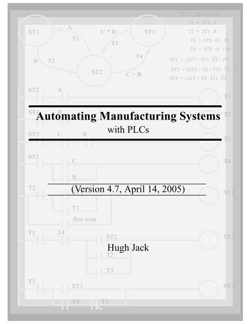
<strong>Automating</strong> <strong>Manufacturing</strong> <strong>Systems</strong><br />
ST3 C B<br />
with PLCs<br />
T2<br />
T3<br />
ST2<br />
C<br />
T4<br />
T2<br />
B<br />
(Version 4.7, April 14, 2005)<br />
ST1<br />
ST1<br />
T1<br />
first scan<br />
T1<br />
T4<br />
ST2<br />
Hugh Jack<br />
T2<br />
ST2<br />
T3<br />
T3<br />
ST3<br />
ST3<br />
T4<br />
T1
page 0<br />
Copyright (c) 1993-2005 Hugh Jack (jackh@gvsu.edu).<br />
Permission is granted to copy, distribute <strong>and</strong>/or modify this document under the<br />
terms of the GNU Free Documentation License, Version 1.2 or any later version<br />
published by the Free Software Foundation; with no Invariant Sections, no<br />
Front-Cover Texts, <strong>and</strong> no Back-Cover Texts. A copy of the license is included<br />
in the section entitled "GNU Free Documentation License".<br />
This document is provided as-is with no warranty, implied or otherwise. There<br />
have been attempts to eliminate errors from this document, but there is no doubt<br />
that errors remain. As a result, the author does not assume any responsibility for<br />
errors <strong>and</strong> omissions, or damages resulting from the use of the information provided.<br />
Additional materials <strong>and</strong> updates for this work will be available at http://claymore.engineer.gvsu.edu/~jackh/books.html
page i<br />
1.1 TODO LIST 1.4<br />
2. PROGRAMMABLELOGICCONTROLLERS .............2.1<br />
2.1 INTRODUCTION 2.1<br />
2.1.1 Ladder Logic 2.1<br />
2.1.2 Programming 2.6<br />
2.1.3 PLC Connections 2.10<br />
2.1.4 Ladder Logic Inputs 2.11<br />
2.1.5 Ladder Logic Outputs 2.12<br />
2.2 A CASE STUDY 2.13<br />
2.3 SUMMARY 2.14<br />
2.4 PRACTICE PROBLEMS 2.15<br />
2.5 PRACTICE PROBLEM SOLUTIONS 2.15<br />
2.6 ASSIGNMENT PROBLEMS 2.16<br />
3. PLCHARDWARE ....................................3.1<br />
3.1 INTRODUCTION 3.1<br />
3.2 INPUTS AND OUTPUTS 3.2<br />
3.2.1 Inputs 3.3<br />
3.2.2 Output Modules 3.7<br />
3.3 RELAYS 3.13<br />
3.4 A CASE STUDY 3.14<br />
3.5 ELECTRICAL WIRING DIAGRAMS 3.15<br />
3.5.1 JIC Wiring Symbols 3.17<br />
3.6 SUMMARY 3.21<br />
3.7 PRACTICE PROBLEMS 3.21<br />
3.8 PRACTICE PROBLEM SOLUTIONS 3.24<br />
3.9 ASSIGNMENT PROBLEMS 3.27<br />
4. LOGICALSENSORS..................................4.1<br />
4.1 INTRODUCTION 4.1<br />
4.2 SENSOR WIRING 4.1<br />
4.2.1 Switches 4.2<br />
4.2.2 Transistor Transistor Logic (TTL) 4.3<br />
4.2.3 Sinking/Sourcing 4.3<br />
4.2.4 Solid State Relays 4.10<br />
4.3 PRESENCE DETECTION 4.11<br />
4.3.1 Contact Switches 4.11<br />
4.3.2 Reed Switches 4.11<br />
4.3.3 Optical (Photoelectric) Sensors 4.12<br />
4.3.4 Capacitive Sensors 4.19<br />
4.3.5 Inductive Sensors 4.23<br />
4.3.6 Ultrasonic 4.25<br />
4.3.7 Hall Effect 4.25
page ii<br />
4.3.8 Fluid Flow 4.26<br />
4.4 SUMMARY 4.26<br />
4.5 PRACTICE PROBLEMS 4.27<br />
4.6 PRACTICE PROBLEM SOLUTIONS 4.30<br />
4.7 ASSIGNMENT PROBLEMS 4.36<br />
5. LOGICALACTUATORS ..............................5.1<br />
5.1 INTRODUCTION 5.1<br />
5.2 SOLENOIDS 5.1<br />
5.3 VALVES 5.2<br />
5.4 CYLINDERS 5.4<br />
5.5 HYDRAULICS 5.6<br />
5.6 PNEUMATICS 5.8<br />
5.7 MOTORS 5.9<br />
5.8 COMPUTERS 5.10<br />
5.9 OTHERS 5.10<br />
5.10 SUMMARY 5.10<br />
5.11 PRACTICE PROBLEMS 5.11<br />
5.12 PRACTICE PROBLEM SOLUTIONS 5.11<br />
5.13 ASSIGNMENT PROBLEMS 5.12<br />
6. BOOLEANLOGICDESIGN............................6.1<br />
6.1 INTRODUCTION 6.1<br />
6.2 BOOLEAN ALGEBRA 6.1<br />
6.3 LOGIC DESIGN 6.6<br />
6.3.1 Boolean Algebra Techniques 6.13<br />
6.4 COMMON LOGIC FORMS 6.14<br />
6.4.1 Complex Gate Forms 6.14<br />
6.4.2 Multiplexers 6.15<br />
6.5 SIMPLE DESIGN CASES 6.17<br />
6.5.1 Basic Logic Functions 6.17<br />
6.5.2 Car Safety System 6.18<br />
6.5.3 Motor Forward/Reverse 6.18<br />
6.5.4 A Burglar Alarm 6.19<br />
6.6 SUMMARY 6.23<br />
6.7 PRACTICE PROBLEMS 6.24<br />
6.8 PRACTICE PROBLEM SOLUTIONS 6.27<br />
6.9 ASSIGNMENT PROBLEMS 6.37<br />
7. KARNAUGHMAPS ..................................7.1<br />
7.1 INTRODUCTION 7.1<br />
7.2 SUMMARY 7.4<br />
7.3 PRACTICE PROBLEMS 7.5
page iii<br />
7.4 PRACTICE PROBLEM SOLUTIONS 7.11<br />
7.5 ASSIGNMENT PROBLEMS 7.17<br />
8. PLCOPERATION ....................................8.1<br />
8.1 INTRODUCTION 8.1<br />
8.2 OPERATION SEQUENCE 8.3<br />
8.2.1 The Input <strong>and</strong> Output Scans 8.4<br />
8.2.2 The Logic Scan 8.4<br />
8.3 PLC STATUS 8.6<br />
8.4 MEMORY TYPES 8.6<br />
8.5 SOFTWARE BASED PLCS 8.7<br />
8.6 SUMMARY 8.7<br />
8.7 PRACTICE PROBLEMS 8.8<br />
8.8 PRACTICE PROBLEM SOLUTIONS 8.8<br />
8.9 ASSIGNMENT PROBLEMS 8.9<br />
9. LATCHES, TIMERS, COUNTERS AND MORE ............9.1<br />
9.1 INTRODUCTION 9.1<br />
9.2 LATCHES 9.2<br />
9.3 TIMERS 9.6<br />
9.4 COUNTERS 9.14<br />
9.5 MASTER CONTROL RELAYS (MCRs) 9.17<br />
9.6 INTERNAL RELAYS 9.19<br />
9.7 DESIGN CASES 9.20<br />
9.7.1 Basic Counters And Timers 9.20<br />
9.7.2 More Timers And Counters 9.21<br />
9.7.3 Deadman Switch 9.22<br />
9.7.4 Conveyor 9.23<br />
9.7.5 Accept/Reject Sorting 9.24<br />
9.7.6 Shear Press 9.26<br />
9.8 SUMMARY 9.27<br />
9.9 PRACTICE PROBLEMS 9.28<br />
9.10 PRACTICE PROBLEM SOLUTIONS 9.32<br />
9.11 ASSIGNMENT PROBLEMS 9.43<br />
10. STRUCTUREDLOGICDESIGN .......................10.1<br />
10.1 INTRODUCTION 10.1<br />
10.2 PROCESS SEQUENCE BITS 10.2<br />
10.3 TIMING DIAGRAMS 10.6<br />
10.4 DESIGN CASES 10.9<br />
10.5 SUMMARY 10.9<br />
10.6 PRACTICE PROBLEMS 10.9<br />
10.7 PRACTICE PROBLEM SOLUTIONS 10.10
page iv<br />
13.11<br />
10.8 ASSIGNMENT PROBLEMS 10.14<br />
11. FLOWCHARTBASEDDESIGN .......................11.1<br />
11.1 INTRODUCTION 11.1<br />
11.2 BLOCK LOGIC 11.4<br />
11.3 SEQUENCE BITS 11.11<br />
11.4 SUMMARY 11.15<br />
11.5 PRACTICE PROBLEMS 11.15<br />
11.6 PRACTICE PROBLEM SOLUTIONS 11.16<br />
11.7 ASSIGNMENT PROBLEMS 11.26<br />
12. STATEBASEDDESIGN..............................12.1<br />
12.1 INTRODUCTION 12.1<br />
12.1.1 State Diagram Example 12.4<br />
12.1.2 Conversion to Ladder Logic 12.7<br />
Block Logic Conversion 12.7<br />
State Equations 12.16<br />
State-Transition Equations 12.24<br />
12.2 SUMMARY 12.29<br />
12.3 PRACTICE PROBLEMS 12.29<br />
12.4 PRACTICE PROBLEM SOLUTIONS 12.34<br />
12.5 ASSIGNMENT PROBLEMS 12.49<br />
13. NUMBERSANDDATA ..............................13.1<br />
13.1 INTRODUCTION 13.1<br />
13.2 NUMERICAL VALUES 13.2<br />
13.2.1 Binary 13.2<br />
Boolean Operations 13.5<br />
Binary Mathematics 13.6<br />
13.2.2 Other Base Number <strong>Systems</strong> 13.10<br />
13.2.3 BCD (Binary Coded Decimal) 13.11<br />
13.3 DATA CHARACTERIZATION 13.11<br />
13.3.1 ASCII (American St<strong>and</strong>ard Code for Information Interchange)<br />
13.3.2 Parity 13.14<br />
13.3.3 Checksums 13.15<br />
13.3.4 Gray Code 13.16<br />
13.4 SUMMARY 13.17<br />
13.5 PRACTICE PROBLEMS 13.17<br />
13.6 PRACTICE PROBLEM SOLUTIONS 13.20<br />
13.7 ASSIGNMENT PROBLEMS 13.23<br />
14. PLCMEMORY......................................14.1<br />
14.1 INTRODUCTION 14.1
page v<br />
14.2 MEMORY ADDRESSES 14.1<br />
14.3 PROGRAM FILES 14.2<br />
14.4 DATA FILES 14.3<br />
14.4.1 User Bit Memory 14.9<br />
14.4.2 Timer Counter Memory 14.10<br />
14.4.3 PLC Status Bits (for PLC-5s <strong>and</strong> Micrologix) 14.12<br />
14.4.4 User Function <strong>Control</strong> Memory 14.13<br />
14.4.5 Integer Memory 14.14<br />
14.4.6 Floating Point Memory 14.14<br />
14.5 SUMMARY 14.14<br />
14.6 PRACTICE PROBLEMS 14.15<br />
14.7 PRACTICE PROBLEM SOLUTIONS 14.15<br />
14.8 ASSIGNMENT PROBLEMS 14.18<br />
15. LADDER LOGIC FUNCTIONS ........................15.1<br />
15.1 INTRODUCTION 15.1<br />
15.2 DATA HANDLING 15.3<br />
15.2.1 Move Functions 15.3<br />
15.2.2 Mathematical Functions 15.5<br />
15.2.3 Conversions 15.10<br />
15.2.4 Array Data Functions 15.11<br />
Statistics 15.12<br />
Block Operations 15.13<br />
15.3 LOGICAL FUNCTIONS 15.15<br />
15.3.1 Comparison of Values 15.15<br />
15.3.2 Boolean Functions 15.21<br />
15.4 DESIGN CASES 15.22<br />
15.4.1 Simple Calculation 15.22<br />
15.4.2 For-Next 15.23<br />
15.4.3 Series Calculation 15.24<br />
15.4.4 Flashing Lights 15.25<br />
15.5 SUMMARY 15.25<br />
15.6 PRACTICE PROBLEMS 15.26<br />
15.7 PRACTICE PROBLEM SOLUTIONS 15.28<br />
15.8 ASSIGNMENT PROBLEMS 15.34<br />
16. ADVANCED LADDER LOGIC FUNCTIONS .............16.1<br />
16.1 INTRODUCTION 16.1<br />
16.2 LIST FUNCTIONS 16.1<br />
16.2.1 Shift Registers 16.1<br />
16.2.2 Stacks 16.3<br />
16.2.3 Sequencers 16.6<br />
16.3 PROGRAM CONTROL 16.9<br />
16.3.1 Branching <strong>and</strong> Looping 16.9
page vi<br />
16.3.2 Fault Detection <strong>and</strong> Interrupts 16.14<br />
16.4 INPUT AND OUTPUT FUNCTIONS 16.18<br />
16.4.1 Immediate I/O Instructions 16.18<br />
16.4.2 Block Transfer Functions 16.20<br />
16.5 DESIGN TECHNIQUES 16.22<br />
16.5.1 State Diagrams 16.22<br />
16.6 DESIGN CASES 16.26<br />
16.6.1 If-Then 16.26<br />
16.6.2 Traffic Light 16.27<br />
16.7 SUMMARY 16.28<br />
16.8 PRACTICE PROBLEMS 16.29<br />
16.9 PRACTICE PROBLEM SOLUTIONS 16.31<br />
16.10 ASSIGNMENT PROBLEMS 16.40<br />
17. OPENCONTROLLERS...............................17.1<br />
17.1 INTRODUCTION 17.1<br />
17.2 IEC 61131 17.2<br />
17.3 OPEN ARCHITECTURE CONTROLLERS 17.3<br />
17.4 SUMMARY 17.4<br />
17.5 PRACTICE PROBLEMS 17.4<br />
17.6 PRACTICE PROBLEM SOLUTIONS 17.4<br />
17.7 ASSIGNMENT PROBLEMS 17.4<br />
18. INSTRUCTIONLISTPROGRAMMING .................18.1<br />
18.1 INTRODUCTION 18.1<br />
18.2 THE IEC 61131 VERSION 18.1<br />
18.3 THE ALLEN-BRADLEY VERSION 18.4<br />
18.4 SUMMARY 18.9<br />
18.5 PRACTICE PROBLEMS 18.10<br />
18.6 PRACTICE PROBLEM SOLUTIONS 18.10<br />
18.7 ASSIGNMENT PROBLEMS 18.10<br />
19. STRUCTUREDTEXTPROGRAMMING ................19.1<br />
19.1 INTRODUCTION 19.1<br />
19.2 THE LANGUAGE 19.2<br />
19.3 SUMMARY 19.19<br />
19.4 PRACTICE PROBLEMS 19.20<br />
19.5 PRACTICE PROBLEM SOLUTIONS 19.20<br />
19.6 ASSIGNMENT PROBLEMS 19.20<br />
20. SEQUENTIALFUNCTIONCHARTS ...................20.1<br />
20.1 INTRODUCTION 20.1<br />
20.2 A COMPARISON OF METHODS 20.16
page vii<br />
20.3 SUMMARY 20.16<br />
20.4 PRACTICE PROBLEMS 20.17<br />
20.5 PRACTICE PROBLEM SOLUTIONS 20.18<br />
20.6 ASSIGNMENT PROBLEMS 20.25<br />
21. FUNCTIONBLOCKPROGRAMMING..................21.1<br />
21.1 INTRODUCTION 21.1<br />
21.2 CREATING FUNCTION BLOCKS 21.3<br />
21.3 DESIGN CASE 21.4<br />
21.4 SUMMARY 21.4<br />
21.5 PRACTICE PROBLEMS 21.5<br />
21.6 PRACTICE PROBLEM SOLUTIONS 21.5<br />
21.7 ASSIGNMENT PROBLEMS 21.5<br />
22. ANALOGINPUTSANDOUTPUTS ....................22.1<br />
22.1 INTRODUCTION 22.1<br />
22.2 ANALOG INPUTS 22.2<br />
22.2.1 Analog Inputs With a PLC 22.9<br />
22.3 ANALOG OUTPUTS 22.13<br />
22.3.1 Analog Outputs With A PLC 22.16<br />
22.3.2 Pulse Width Modulation (PWM) Outputs 22.18<br />
22.3.3 Shielding 22.20<br />
22.4 DESIGN CASES 22.22<br />
22.4.1 <strong>Process</strong> Monitor 22.22<br />
22.5 SUMMARY 22.22<br />
22.6 PRACTICE PROBLEMS 22.23<br />
22.7 PRACTICE PROBLEM SOLUTIONS 22.24<br />
22.8 ASSIGNMENT PROBLEMS 22.29<br />
23. CONTINUOUSSENSORS ............................23.1<br />
23.1 INTRODUCTION 23.1<br />
23.2 INDUSTRIAL SENSORS 23.2<br />
23.2.1 Angular Displacement 23.3<br />
Potentiometers 23.3<br />
23.2.2 Encoders 23.4<br />
Tachometers 23.8<br />
23.2.3 Linear Position 23.8<br />
Potentiometers 23.8<br />
Linear Variable Differential Transformers (LVDT)23.9<br />
Moire Fringes 23.11<br />
Accelerometers 23.12<br />
23.2.4 Forces <strong>and</strong> Moments 23.15<br />
Strain Gages 23.15<br />
Piezoelectric 23.18
page viii<br />
23.2.5 Liquids <strong>and</strong> Gases 23.20<br />
Pressure 23.21<br />
Venturi Valves 23.22<br />
Coriolis Flow Meter 23.23<br />
Magnetic Flow Meter 23.24<br />
Ultrasonic Flow Meter 23.24<br />
Vortex Flow Meter 23.24<br />
Positive Displacement Meters 23.25<br />
Pitot Tubes 23.25<br />
23.2.6 Temperature 23.25<br />
Resistive Temperature Detectors (RTDs) 23.26<br />
Thermocouples 23.26<br />
Thermistors 23.28<br />
Other Sensors 23.30<br />
23.2.7 Light 23.30<br />
Light Dependant Resistors (LDR) 23.30<br />
23.2.8 Chemical 23.31<br />
pH 23.31<br />
Conductivity 23.31<br />
23.2.9 Others 23.32<br />
23.3 INPUT ISSUES 23.32<br />
23.4 SENSOR GLOSSARY 23.37<br />
23.5 SUMMARY 23.38<br />
23.6 REFERENCES 23.39<br />
23.7 PRACTICE PROBLEMS 23.39<br />
23.8 PRACTICE PROBLEM SOLUTIONS 23.40<br />
23.9 ASSIGNMENT PROBLEMS 23.42<br />
24. CONTINUOUSACTUATORS .........................24.1<br />
24.1 INTRODUCTION 24.1<br />
24.2 ELECTRIC MOTORS 24.1<br />
24.2.1 Basic Brushed DC Motors 24.3<br />
24.2.2 AC Motors 24.7<br />
24.2.3 Brushless DC Motors 24.15<br />
24.2.4 Stepper Motors 24.17<br />
24.2.5 Wound Field Motors 24.19<br />
24.3 HYDRAULICS 24.23<br />
24.4 OTHER SYSTEMS 24.24<br />
24.5 SUMMARY 24.25<br />
24.6 PRACTICE PROBLEMS 24.25<br />
24.7 PRACTICE PROBLEM SOLUTIONS 24.26<br />
24.8 ASSIGNMENT PROBLEMS 24.26<br />
25. CONTINUOUSCONTROL ............................25.1<br />
25.1 INTRODUCTION 25.1
page ix<br />
25.2 CONTROL OF LOGICAL ACTUATOR SYSTEMS 25.4<br />
25.3 CONTROL OF CONTINUOUS ACTUATOR SYSTEMS 25.5<br />
25.3.1 Block Diagrams 25.5<br />
25.3.2 Feedback <strong>Control</strong> <strong>Systems</strong> 25.6<br />
25.3.3 Proportional <strong>Control</strong>lers 25.8<br />
25.3.4 PID <strong>Control</strong> <strong>Systems</strong> 25.12<br />
25.4 DESIGN CASES 25.14<br />
25.4.1 Oven Temperature <strong>Control</strong> 25.14<br />
25.4.2 Water Tank Level <strong>Control</strong> 25.17<br />
25.5 SUMMARY 25.20<br />
25.6 PRACTICE PROBLEMS 25.20<br />
25.7 PRACTICE PROBLEM SOLUTIONS 25.21<br />
25.8 ASSIGNMENT PROBLEMS 25.26<br />
26. FUZZYLOGIC......................................26.1<br />
26.1 INTRODUCTION 26.1<br />
26.2 COMMERCIAL CONTROLLERS 26.7<br />
26.3 REFERENCES 26.7<br />
26.4 SUMMARY 26.7<br />
26.5 PRACTICE PROBLEMS 26.8<br />
26.6 PRACTICE PROBLEM SOLUTIONS 26.8<br />
26.7 ASSIGNMENT PROBLEMS 26.8<br />
27. SERIALCOMMUNICATION ..........................27.1<br />
27.1 INTRODUCTION 27.1<br />
27.2 SERIAL COMMUNICATIONS 27.2<br />
27.2.1 RS-232 27.5<br />
ASCII Functions 27.9<br />
27.3 PARALLEL COMMUNICATIONS 27.13<br />
27.4 DESIGN CASES 27.14<br />
27.4.1 PLC Interface To a Robot 27.14<br />
27.5 SUMMARY 27.15<br />
27.6 PRACTICE PROBLEMS 27.15<br />
27.7 PRACTICE PROBLEM SOLUTIONS 27.16<br />
27.8 ASSIGNMENT PROBLEMS 27.18<br />
28. NETWORKING .....................................28.1<br />
28.1 INTRODUCTION 28.1<br />
28.1.1 Topology 28.2<br />
28.1.2 OSI Network Model 28.3<br />
28.1.3 Networking Hardware 28.5<br />
28.1.4 <strong>Control</strong> Network Issues 28.7<br />
28.2 NETWORK STANDARDS 28.8<br />
28.2.1 Devicenet 28.8
page x<br />
28.2.2 CANbus 28.12<br />
28.2.3 <strong>Control</strong>net 28.13<br />
28.2.4 Ethernet 28.14<br />
28.2.5 Profibus 28.15<br />
28.2.6 Sercos 28.15<br />
28.3 PROPRIETARY NETWORKS 28.16<br />
28.3.1 Data Highway 28.16<br />
28.4 NETWORK COMPARISONS 28.20<br />
28.5 DESIGN CASES 28.22<br />
28.5.1 Devicenet 28.22<br />
28.6 SUMMARY 28.23<br />
28.7 PRACTICE PROBLEMS 28.23<br />
28.8 PRACTICE PROBLEM SOLUTIONS 28.24<br />
28.9 ASSIGNMENT PROBLEMS 28.28<br />
29. INTERNET .........................................29.1<br />
29.1 INTRODUCTION 29.1<br />
29.1.1 Computer Addresses 29.2<br />
IPV6 29.3<br />
29.1.2 Phone Lines 29.3<br />
29.1.3 Mail Transfer Protocols 29.3<br />
29.1.4 FTP - File Transfer Protocol 29.4<br />
29.1.5 HTTP - Hypertext Transfer Protocol 29.4<br />
29.1.6 Novell 29.4<br />
29.1.7 Security 29.5<br />
Firewall 29.5<br />
IP Masquerading 29.5<br />
29.1.8 HTML - Hyper Text Markup Language 29.5<br />
29.1.9 URLs 29.6<br />
29.1.10 Encryption 29.6<br />
29.1.11 Compression 29.7<br />
29.1.12 Clients <strong>and</strong> Servers 29.7<br />
29.1.13 Java 29.9<br />
29.1.14 Javascript 29.9<br />
29.1.15 CGI 29.9<br />
29.1.16 ActiveX 29.9<br />
29.1.17 Graphics 29.10<br />
29.2 DESIGN CASES 29.10<br />
29.2.1 Remote Monitoring System 29.10<br />
29.3 SUMMARY 29.11<br />
29.4 PRACTICE PROBLEMS 29.11<br />
29.5 PRACTICE PROBLEM SOLUTIONS 29.11<br />
29.6 ASSIGNMENT PROBLEMS 29.11<br />
30. HUMANMACHINEINTERFACES(HMI) ...............30.1
page xi<br />
30.1 INTRODUCTION 30.1<br />
30.2 HMI/MMI DESIGN 30.2<br />
30.3 DESIGN CASES 30.3<br />
30.4 SUMMARY 30.3<br />
30.5 PRACTICE PROBLEMS 30.4<br />
30.6 PRACTICE PROBLEM SOLUTIONS 30.4<br />
30.7 ASSIGNMENT PROBLEMS 30.4<br />
31. ELECTRICALDESIGNANDCONSTRUCTION ..........31.1<br />
31.1 INTRODUCTION 31.1<br />
31.2 ELECTRICAL WIRING DIAGRAMS 31.1<br />
31.2.1 Selecting Voltages 31.8<br />
31.2.2 Grounding 31.9<br />
31.2.3 Wiring 31.12<br />
31.2.4 Suppressors 31.13<br />
31.2.5 PLC Enclosures 31.14<br />
31.2.6 Wire <strong>and</strong> Cable Grouping 31.16<br />
31.3 FAIL-SAFE DESIGN 31.17<br />
31.4 SAFETY RULES SUMMARY 31.18<br />
31.5 REFERENCES 31.20<br />
31.6 SUMMARY 31.20<br />
31.7 PRACTICE PROBLEMS 31.20<br />
31.8 PRACTICE PROBLEM SOLUTIONS 31.20<br />
31.9 ASSIGNMENT PROBLEMS 31.20<br />
32. SOFTWAREENGINEERING ..........................32.1<br />
32.1 INTRODUCTION 32.1<br />
32.1.1 Fail Safe Design 32.1<br />
32.2 DEBUGGING 32.2<br />
32.2.1 Troubleshooting 32.3<br />
32.2.2 Forcing 32.3<br />
32.3 PROCESS MODELLING 32.3<br />
32.4 PROGRAMMING FOR LARGE SYSTEMS 32.8<br />
32.4.1 Developing a Program Structure 32.8<br />
32.4.2 Program Verification <strong>and</strong> Simulation 32.11<br />
32.5 DOCUMENTATION 32.12<br />
32.6 COMMISIONING 32.20<br />
32.7 REFERENCES 32.20<br />
32.8 SUMMARY 32.21<br />
32.9 PRACTICE PROBLEMS 32.21<br />
32.10 PRACTICE PROBLEM SOLUTIONS 32.21<br />
32.11 ASSIGNMENT PROBLEMS 32.21<br />
33. SELECTINGAPLC..................................33.1
page xii<br />
33.1 INTRODUCTION 33.1<br />
33.2 SPECIAL I/O MODULES 33.6<br />
33.3 SUMMARY 33.9<br />
33.4 PRACTICE PROBLEMS 33.10<br />
33.5 PRACTICE PROBLEM SOLUTIONS 33.10<br />
33.6 ASSIGNMENT PROBLEMS 33.10<br />
34. FUNCTIONREFERENCE.............................34.1<br />
34.1 FUNCTION DESCRIPTIONS 34.1<br />
34.1.1 General Functions 34.1<br />
34.1.2 Program <strong>Control</strong> 34.3<br />
34.1.3 Timers <strong>and</strong> Counters 34.5<br />
34.1.4 Compare 34.10<br />
34.1.5 Calculation <strong>and</strong> Conversion 34.14<br />
34.1.6 Logical 34.20<br />
34.1.7 Move 34.21<br />
34.1.8 File 34.22<br />
34.1.9 List 34.27<br />
34.1.10 Program <strong>Control</strong> 34.30<br />
34.1.11 Advanced Input/Output 34.34<br />
34.1.12 String 34.37<br />
34.2 DATA TYPES 34.42<br />
35. COMBINEDGLOSSARYOFTERMS ...................35.1<br />
35.1 A 35.1<br />
35.2 B 35.2<br />
35.3 C 35.5<br />
35.4 D 35.9<br />
35.5 E 35.11<br />
35.6 F 35.12<br />
35.7 G 35.13<br />
35.8 H 35.14<br />
35.9 I 35.14<br />
35.10 J 35.16<br />
35.11 K 35.16<br />
35.12 L 35.16<br />
35.13 M 35.17<br />
35.14 N 35.19<br />
35.15 O 35.20<br />
35.16 P 35.21<br />
35.17 Q 35.23<br />
35.18 R 35.23<br />
35.19 S 35.25<br />
35.20 T 35.27
page xiii<br />
35.21 U 35.28<br />
35.22 V 35.29<br />
35.23 W 35.29<br />
35.24 X 35.30<br />
35.25 Y 35.30<br />
35.26 Z 35.30<br />
36. PLCREFERENCES ..................................36.1<br />
36.1 SUPPLIERS 36.1<br />
36.2 PROFESSIONAL INTEREST GROUPS 36.2<br />
36.3 PLC/DISCRETE CONTROL REFERENCES 36.2<br />
37. GNUFreeDocumentationLicense .......................37.1<br />
37.1 PREAMBLE 37.1<br />
37.2 APPLICABILITY AND DEFINITIONS 37.1<br />
37.3 VERBATIM COPYING 37.2<br />
37.4 COPYING IN QUANTITY 37.3<br />
37.5 MODIFICATIONS 37.3<br />
37.6 COMBINING DOCUMENTS 37.5<br />
37.7 COLLECTIONS OF DOCUMENTS 37.5<br />
37.8 AGGREGATION WITH INDEPENDENT WORKS 37.6<br />
37.9 TRANSLATION 37.6<br />
37.10 TERMINATION 37.6<br />
37.11 FUTURE REVISIONS OF THIS LICENSE 37.6<br />
37.12 How to use this License for your documents 37.7
plc wiring - 1.1<br />
PREFACE<br />
Some sections are still in point form. The last major task of this book<br />
will be to write the preface to reflect the book contents <strong>and</strong> all of the features.<br />
<strong>Control</strong> systems apply artificial means to change the behavior of a system. The<br />
type of control problem often determines the type of control system that can be used. Each<br />
controller will be designed to meet a specific objective. The major types of control are<br />
shown in Figure 1.1.<br />
CONTROL<br />
CONTINUOUS<br />
DISCRETE<br />
LINEAR NON_LINEAR CONDITIONAL SEQUENTIAL<br />
EVENT BASED<br />
e.g. MRAC<br />
TEMPORAL<br />
e.g. PID<br />
BOOLEAN<br />
e.g. FUZZY LOGIC<br />
e.g. COUNTERS<br />
EXPERT SYSTEMS e.g. TIMERS<br />
Figure 1.1<br />
<strong>Control</strong> Dichotomy<br />
• Continuous - The values to be controlled change smoothly. e.g. the speed of a car.<br />
• Logical - The value to be controlled are easily described as on-off. e.g. the car<br />
motor is on-off. NOTE: all systems are continuous but they can be treated as<br />
logical for simplicity.<br />
e.g. “When I do this, that always happens!” For example, when the power<br />
is turned on, the press closes!<br />
• Linear - Can be described with a simple differential equation. This is the preferred<br />
starting point for simplicity, <strong>and</strong> a common approximation for real world<br />
problems.<br />
e.g. A car can be driving around a track <strong>and</strong> can pass same the same spot at<br />
a constant velocity. But, the longer the car runs, the mass decreases, <strong>and</strong><br />
it travels faster, but requires less gas, etc. Basically, the math gets
plc wiring - 1.2<br />
tougher, <strong>and</strong> the problem becomes non-linear.<br />
e.g. We are driving the perfect car with no friction, with no drag, <strong>and</strong> can<br />
predict how it will work perfectly.<br />
• Non-Linear - Not Linear. This is how the world works <strong>and</strong> the mathematics<br />
become much more complex.<br />
e.g. As rocket approaches sun, gravity increases, so control must change.<br />
• Sequential - A logical controller that will keep track of time <strong>and</strong> previous events.<br />
The difference between these control systems can be emphasized by considering a<br />
simple elevator. An elevator is a car that travels between floors, stopping at precise<br />
heights. There are certain logical constraints used for safety <strong>and</strong> convenience. The points<br />
below emphasize different types of control problems in the elevator.<br />
Logical:<br />
1. The elevator must move towards a floor when a button is pushed.<br />
2. The elevator must open a door when it is at a floor.<br />
3. It must have the door closed before it moves.<br />
etc.<br />
Linear:<br />
1. If the desired position changes to a new value, accelerate quickly<br />
towards the new position.<br />
2. As the elevator approaches the correct position, slow down.<br />
Non-linear:<br />
1 Accelerate slowly to start.<br />
2. Decelerate as you approach the final position.<br />
3. Allow faster motion while moving.<br />
4. Compensate for cable stretch, <strong>and</strong> changing spring constant, etc.<br />
Logical <strong>and</strong> sequential control is preferred for system design. These systems are<br />
more stable, <strong>and</strong> often lower cost. Most continuous systems can be controlled logically.<br />
But, some times we will encounter a system that must be controlled continuously. When<br />
this occurs the control system design becomes more dem<strong>and</strong>ing. When improperly controlled,<br />
continuous systems may be unstable <strong>and</strong> become dangerous.<br />
When a system is well behaved we say it is self regulating. These systems don’t<br />
need to be closely monitored, <strong>and</strong> we use open loop control. An open loop controller will<br />
set a desired position for a system, but no sensors are used to verify the position. When a<br />
system must be constantly monitored <strong>and</strong> the control output adjusted we say it is closed<br />
loop. A cruise control in a car is an excellent example. This will monitor the actual speed<br />
of a car, <strong>and</strong> adjust the speed to meet a set target speed.<br />
Many control technologies are available for control. Early control systems relied<br />
upon mechanisms <strong>and</strong> electronics to build controlled. Most modern controllers use a com-
plc wiring - 1.3<br />
puter to achieve control. The most flexible of these controllers is the PLC (Programmable<br />
Logic <strong>Control</strong>ler).<br />
<br />
Purpose<br />
• Most education focuses on continuous control systems.<br />
• In practice most contemporary control systems make use of computers.<br />
• Computer based control is inherently different than continuous systems.<br />
• The purpose of this book is to address discrete control systems using<br />
common control systems.<br />
• The objective is to prepare the reader to implement a control system from<br />
beginning to end, including planning <strong>and</strong> design of hardware <strong>and</strong> software.<br />
Audience Background<br />
• The intended reader should have a basic background in technology or<br />
engineering.<br />
A first course in electric circuits, including AC/DC circuits is useful for the<br />
reader, more advanced topics will be explained as necessary.<br />
Editorial notes <strong>and</strong> aids<br />
Sections labeled Aside: are for topics that would be of interest to one discipline,<br />
such as electrical or mechanical.<br />
Sections labeled Note: are for clarification, to provide hints, or to add<br />
explanation.<br />
Each chapter supports about 1-4 lecture hours depending upon students<br />
background <strong>and</strong> level in the curriculum.<br />
Topics are organized to allow students to start laboratory work earlier in the<br />
semester.<br />
sections begin with a topic list to help set thoughts.<br />
Objective given at the beginning of each chapter.<br />
Summary at the end of each chapter to give big picture.<br />
significant use of figures to emphasize physical implementations.<br />
worked examples <strong>and</strong> case studies.<br />
problems at ends of chapters with solutions.<br />
glossary.<br />
Platform
plc wiring - 1.4<br />
This book supports Allen Bradley micrologix, PLC-5s, SLC500 series<br />
1.1 TODO LIST<br />
- Finish writing chapters<br />
* - structured text chapter<br />
* - FBD chapter<br />
- fuzzy logic chapter<br />
* - internet chapter<br />
-hmichapter<br />
- modify chapters<br />
* - add topic hierarchies to this chapter. split into basics, logic design techniques,<br />
new stuff, integration, professional design for curriculum design<br />
* - electrical wiring chapter<br />
- fix wiring <strong>and</strong> other issues in the implementation chapter<br />
- software chapter - improve P&ID section<br />
- appendices - complete list of instruction data types in appendix<br />
- small items<br />
- update serial IO slides<br />
- all chapters<br />
* - grammar <strong>and</strong> spelling check<br />
* - update powerpoint slides<br />
* - add a resources web page with links<br />
- links to software/hardware vendors, iec1131, etc.<br />
- pictures of hardware <strong>and</strong> controls cabinet
plc wiring - 2.1<br />
2. PROGRAMMABLE LOGIC CONTROLLERS<br />
Topics:<br />
• PLC History<br />
• Ladder Logic <strong>and</strong> Relays<br />
• PLC Programming<br />
• PLC Operation<br />
• An Example<br />
Objectives:<br />
• Know general PLC issues<br />
• To be able to write simple ladder logic programs<br />
• Underst<strong>and</strong> the operation of a PLC<br />
2.1 INTRODUCTION<br />
<strong>Control</strong> engineering has evolved over time. In the past humans were the main<br />
method for controlling a system. More recently electricity has been used for control <strong>and</strong><br />
early electrical control was based on relays. These relays allow power to be switched on<br />
<strong>and</strong> off without a mechanical switch. It is common to use relays to make simple logical<br />
control decisions. The development of low cost computer has brought the most recent revolution,<br />
the Programmable Logic <strong>Control</strong>ler (PLC). The advent of the PLC began in the<br />
1970s, <strong>and</strong> has become the most common choice for manufacturing controls.<br />
PLCs have been gaining popularity on the factory floor <strong>and</strong> will probably remain<br />
predominant for some time to come. Most of this is because of the advantages they offer.<br />
• Cost effective for controlling complex systems.<br />
• Flexible <strong>and</strong> can be reapplied to control other systems quickly <strong>and</strong> easily.<br />
• Computational abilities allow more sophisticated control.<br />
• Trouble shooting aids make programming easier <strong>and</strong> reduce downtime.<br />
• Reliable components make these likely to operate for years before failure.<br />
2.1.1 Ladder Logic<br />
Ladder logic is the main programming method used for PLCs. As mentioned<br />
before, ladder logic has been developed to mimic relay logic. The decision to use the relay
plc wiring - 2.2<br />
logic diagrams was a strategic one. By selecting ladder logic as the main programming<br />
method, the amount of retraining needed for engineers <strong>and</strong> tradespeople was greatly<br />
reduced.<br />
Modern control systems still include relays, but these are rarely used for logic. A<br />
relay is a simple device that uses a magnetic field to control a switch, as pictured in Figure<br />
2.1. When a voltage is applied to the input coil, the resulting current creates a magnetic<br />
field. The magnetic field pulls a metal switch (or reed) towards it <strong>and</strong> the contacts touch,<br />
closing the switch. The contact that closes when the coil is energized is called normally<br />
open. The normally closed contacts touch when the input coil is not energized. Relays are<br />
normally drawn in schematic form using a circle to represent the input coil. The output<br />
contacts are shown with two parallel lines. Normally open contacts are shown as two<br />
lines, <strong>and</strong> will be open (non-conducting) when the input is not energized. Normally closed<br />
contacts are shown with two lines with a diagonal line through them. When the input coil<br />
is not energized the normally closed contacts will be closed (conducting).
plc wiring - 2.3<br />
input coil<br />
OR<br />
normally<br />
closed<br />
normally<br />
open<br />
OR<br />
Figure 2.1<br />
Simple Relay Layouts <strong>and</strong> Schematics<br />
Relays are used to let one power source close a switch for another (often high current)<br />
power source, while keeping them isolated. An example of a relay in a simple control<br />
application is shown in Figure 2.2. In this system the first relay on the left is used as normally<br />
closed, <strong>and</strong> will allow current to flow until a voltage is applied to the input A. The<br />
second relay is normally open <strong>and</strong> will not allow current to flow until a voltage is applied<br />
to the input B. If current is flowing through the first two relays then current will flow<br />
through the coil in the third relay, <strong>and</strong> close the switch for output C. This circuit would<br />
normally be drawn in the ladder logic form. This can be read logically as C will be on if A<br />
is off <strong>and</strong> B is on.
plc wiring - 2.4<br />
115VAC<br />
wall plug<br />
relay logic<br />
input A<br />
(normally closed)<br />
input B<br />
(normally open)<br />
output C<br />
(normally open)<br />
A B C<br />
ladder logic<br />
Figure 2.2<br />
A Simple Relay <strong>Control</strong>ler<br />
The example in Figure 2.2 does not show the entire control system, but only the<br />
logic. When we consider a PLC there are inputs, outputs, <strong>and</strong> the logic. Figure 2.3 shows a<br />
more complete representation of the PLC. Here there are two inputs from push buttons.<br />
We can imagine the inputs as activating 24V DC relay coils in the PLC. This in turn drives<br />
an output relay that switches 115V AC, that will turn on a light. Note, in actual PLCs<br />
inputs are never relays, but outputs are often relays. The ladder logic in the PLC is actually<br />
a computer program that the user can enter <strong>and</strong> change. Notice that both of the input push<br />
buttons are normally open, but the ladder logic inside the PLC has one normally open contact,<br />
<strong>and</strong> one normally closed contact. Do not think that the ladder logic in the PLC needs<br />
to match the inputs or outputs. Many beginners will get caught trying to make the ladder<br />
logic match the input types.
plc wiring - 2.5<br />
push buttons<br />
power<br />
supply<br />
+24V<br />
com.<br />
PLC<br />
inputs<br />
ladder<br />
logic<br />
A B C<br />
outputs<br />
115Vac<br />
AC power<br />
light<br />
neut.<br />
Figure 2.3<br />
A PLC Illustrated With Relays<br />
Many relays also have multiple outputs (throws) <strong>and</strong> this allows an output relay to<br />
also be an input simultaneously. The circuit shown in Figure 2.4 is an example of this, it is<br />
called a seal in circuit. In this circuit the current can flow through either branch of the circuit,<br />
through the contacts labelled A or B. The input B will only be on when the output B<br />
is on. If B is off, <strong>and</strong> A is energized, then B will turn on. If B turns on then the input B will<br />
turn on, <strong>and</strong> keep output B on even if input A goes off. After B is turned on the output B<br />
will not turn off.
plc wiring - 2.6<br />
A<br />
B<br />
B<br />
Note: When A is pushed, the output B will turn on, <strong>and</strong><br />
the input B will also turn on <strong>and</strong> keep B on permanently<br />
- until power is removed.<br />
Note: The line on the right is being left off intentionally<br />
<strong>and</strong> is implied in these diagrams.<br />
Figure 2.4<br />
A Seal-in Circuit<br />
2.1.2 Programming<br />
The first PLCs were programmed with a technique that was based on relay logic<br />
wiring schematics. This eliminated the need to teach the electricians, technicians <strong>and</strong> engineers<br />
how to program a computer - but, this method has stuck <strong>and</strong> it is the most common<br />
technique for programming PLCs today. An example of ladder logic can be seen in Figure<br />
2.5. To interpret this diagram imagine that the power is on the vertical line on the left h<strong>and</strong><br />
side, we call this the hot rail. On the right h<strong>and</strong> side is the neutral rail. In the figure there<br />
are two rungs, <strong>and</strong> on each rung there are combinations of inputs (two vertical lines) <strong>and</strong><br />
outputs (circles). If the inputs are opened or closed in the right combination the power can<br />
flow from the hot rail, through the inputs, to power the outputs, <strong>and</strong> finally to the neutral<br />
rail. An input can come from a sensor, switch, or any other type of sensor. An output will<br />
be some device outside the PLC that is switched on or off, such as lights or motors. In the<br />
top rung the contacts are normally open <strong>and</strong> normally closed. Which means if input A is on<br />
<strong>and</strong> input B is off, then power will flow through the output <strong>and</strong> activate it. Any other combination<br />
of input values will result in the output X being off.
plc wiring - 2.7<br />
HOT<br />
A B X<br />
NEUTRAL<br />
C<br />
D<br />
G<br />
Y<br />
E<br />
F<br />
H<br />
INPUTS<br />
OUTPUTS<br />
Note: Power needs to flow through some combination of the inputs<br />
(A,B,C,D,E,F,G,H) to turn on outputs (X,Y).<br />
Figure 2.5<br />
A Simple Ladder Logic Diagram<br />
The second rung of Figure 2.5 is more complex, there are actually multiple combinations<br />
of inputs that will result in the output Y turning on. On the left most part of the<br />
rung, power could flow through the top if C is off <strong>and</strong> D is on. Power could also (<strong>and</strong><br />
simultaneously) flow through the bottom if both E <strong>and</strong> F are true. This would get power<br />
half way across the rung, <strong>and</strong> then if G or H is true the power will be delivered to output Y.<br />
In later chapters we will examine how to interpret <strong>and</strong> construct these diagrams.<br />
There are other methods for programming PLCs. One of the earliest techniques<br />
involved mnemonic instructions. These instructions can be derived directly from the ladder<br />
logic diagrams <strong>and</strong> entered into the PLC through a simple programming terminal. An<br />
example of mnemonics is shown in Figure 2.6. In this example the instructions are read<br />
one line at a time from top to bottom. The first line 00000 has the instruction LDN (input<br />
load <strong>and</strong> not) for input 00001. This will examine the input to the PLC <strong>and</strong> if it is off it will<br />
remember a 1 (or true), if it is on it will remember a 0 (or false). The next line uses an LD<br />
(input load) statement to look at the input. If the input is off it remembers a 0, if the input<br />
is on it remembers a 1 (note: this is the reverse of the LD). The AND statement recalls the<br />
last two numbers remembered <strong>and</strong> if the are both true the result is a 1, otherwise the result<br />
is a 0. This result now replaces the two numbers that were recalled, <strong>and</strong> there is only one<br />
number remembered. The process is repeated for lines 00003 <strong>and</strong> 00004, but when these<br />
are done there are now three numbers remembered. The oldest number is from the AND,<br />
the newer numbers are from the two LD instructions. The AND in line 00005 combines the<br />
results from the last LD instructions <strong>and</strong> now there are two numbers remembered. The OR<br />
instruction takes the two numbers now remaining <strong>and</strong> if either one is a 1 the result is a 1,<br />
otherwise the result is a 0. This result replaces the two numbers, <strong>and</strong> there is now a single
plc wiring - 2.8<br />
number there. The last instruction is the ST (store output) that will look at the last value<br />
stored <strong>and</strong> if it is 1, the output will be turned on, if it is 0 the output will be turned off.<br />
00000<br />
00001<br />
00002<br />
00003<br />
00004<br />
00005<br />
00006<br />
LDN<br />
LD<br />
AND<br />
LD<br />
LD<br />
AND<br />
OR<br />
ST<br />
END<br />
00001<br />
00002<br />
00003<br />
00004<br />
00007 00107<br />
00008<br />
00001 00002<br />
the mnemonic code is equivalent to<br />
the ladder logic below<br />
00107<br />
00003 00004<br />
END<br />
Figure 2.6<br />
An Example of a Mnemonic Program <strong>and</strong> Equivalent Ladder Logic<br />
The ladder logic program in Figure 2.6, is equivalent to the mnemonic program.<br />
Even if you have programmed a PLC with ladder logic, it will be converted to mnemonic<br />
form before being used by the PLC. In the past mnemonic programming was the most<br />
common, but now it is uncommon for users to even see mnemonic programs.<br />
Sequential Function Charts (SFCs) have been developed to accommodate the programming<br />
of more advanced systems. These are similar to flowcharts, but much more<br />
powerful. The example seen in Figure 2.7 is doing two different things. To read the chart,<br />
start at the top where is says start. Below this there is the double horizontal line that says<br />
follow both paths. As a result the PLC will start to follow the branch on the left <strong>and</strong> right<br />
h<strong>and</strong> sides separately <strong>and</strong> simultaneously. On the left there are two functions the first one<br />
is the power up function. This function will run until it decides it is done, <strong>and</strong> the power<br />
down function will come after. On the right h<strong>and</strong> side is the flash function, this will run<br />
until it is done. These functions look unexplained, but each function, such as power up<br />
will be a small ladder logic program. This method is much different from flowcharts<br />
because it does not have to follow a single path through the flowchart.
plc wiring - 2.9<br />
Start<br />
power up<br />
Execution follows<br />
multiple paths<br />
power down<br />
flash<br />
End<br />
Figure 2.7<br />
An Example of a Sequential Function Chart<br />
Structured Text programming has been developed as a more modern programming<br />
language. It is quite similar to languages such as BASIC. A simple example is shown in<br />
Figure 2.8. This example uses a PLC memory location N7:0. This memory location is for<br />
an integer, as will be explained later in the book. The first line of the program sets the<br />
value to 0. The next line begins a loop, <strong>and</strong> will be where the loop returns to. The next line<br />
recalls the value in location N7:0, adds 1 to it <strong>and</strong> returns it to the same location. The next<br />
line checks to see if the loop should quit. If N7:0 is greater than or equal to 10, then the<br />
loop will quit, otherwise the computer will go back up to the REPEAT statement continue<br />
from there. Each time the program goes through this loop N7:0 will increase by 1 until the<br />
value reaches 10.<br />
N7:0 := 0;<br />
REPEAT<br />
N7:0 := N7:0 + 1;<br />
UNTIL N7:0 >= 10<br />
END_REPEAT;<br />
Figure 2.8<br />
An Example of a Structured Text Program
plc wiring - 2.10<br />
2.1.3 PLC Connections<br />
When a process is controlled by a PLC it uses inputs from sensors to make decisions<br />
<strong>and</strong> update outputs to drive actuators, as shown in Figure 2.9. The process is a real<br />
process that will change over time. Actuators will drive the system to new states (or modes<br />
of operation). This means that the controller is limited by the sensors available, if an input<br />
is not available, the controller will have no way to detect a condition.<br />
PROCESS<br />
Feedback from<br />
sensors/switches<br />
Connections to<br />
actuators<br />
PLC<br />
Figure 2.9<br />
The Separation of <strong>Control</strong>ler <strong>and</strong> <strong>Process</strong><br />
The control loop is a continuous cycle of the PLC reading inputs, solving the ladder<br />
logic, <strong>and</strong> then changing the outputs. Like any computer this does not happen<br />
instantly. Figure 2.10 shows the basic operation cycle of a PLC. When power is turned on<br />
initially the PLC does a quick sanity check to ensure that the hardware is working properly.<br />
If there is a problem the PLC will halt <strong>and</strong> indicate there is an error. For example, if<br />
the PLC backup battery is low <strong>and</strong> power was lost, the memory will be corrupt <strong>and</strong> this<br />
will result in a fault. If the PLC passes the sanity check it will then scan (read) all the<br />
inputs. After the inputs values are stored in memory the ladder logic will be scanned<br />
(solved) using the stored values - not the current values. This is done to prevent logic<br />
problems when inputs change during the ladder logic scan. When the ladder logic scan is<br />
complete the outputs will be scanned (the output values will be changed). After this the<br />
system goes back to do a sanity check, <strong>and</strong> the loop continues indefinitely. Unlike normal<br />
computers, the entire program will be run every scan. Typical times for each of the stages<br />
is in the order of milliseconds.
plc wiring - 2.11<br />
PLC program changes outputs<br />
by examining inputs<br />
Read inputs<br />
THE<br />
CONTROL<br />
LOOP<br />
Set new outputs<br />
Power turned on<br />
<strong>Process</strong> changes <strong>and</strong> PLC pauses<br />
while it checks its own operation<br />
Figure 2.10<br />
The Scan Cycle of a PLC<br />
2.1.4 Ladder Logic Inputs<br />
PLC inputs are easily represented in ladder logic. In Figure 2.11 there are three<br />
types of inputs shown. The first two are normally open <strong>and</strong> normally closed inputs, discussed<br />
previously. The IIT (Immediate InpuT) function allows inputs to be read after the<br />
input scan, while the ladder logic is being scanned. This allows ladder logic to examine<br />
input values more often than once every cycle.<br />
x<br />
x<br />
Normally open, an active input x will close the contact<br />
<strong>and</strong> allow power to flow.<br />
Normally closed, power flows when the input x is not open.<br />
IIT<br />
x<br />
immediate inputs will take current values, not those from<br />
the previous input scan. (Note: this instruction is actually<br />
an output that will update the input table with the current<br />
input values. Other input contacts can now be used to<br />
examine the new values.)<br />
Figure 2.11<br />
Ladder Logic Inputs
plc wiring - 2.12<br />
2.1.5 Ladder Logic Outputs<br />
In ladder logic there are multiple types of outputs, but these are not consistently<br />
available on all PLCs. Some of the outputs will be externally connected to devices outside<br />
the PLC, but it is also possible to use internal memory locations in the PLC. Six types of<br />
outputs are shown in Figure 2.12. The first is a normal output, when energized the output<br />
will turn on, <strong>and</strong> energize an output. The circle with a diagonal line through is a normally<br />
on output. When energized the output will turn off. This type of output is not available on<br />
all PLC types. When initially energized the OSR (One Shot Relay) instruction will turn on<br />
for one scan, but then be off for all scans after, until it is turned off. The L (latch) <strong>and</strong> U<br />
(unlatch) instructions can be used to lock outputs on. When an L output is energized the<br />
output will turn on indefinitely, even when the output coil is deenergized. The output can<br />
only be turned off using a U output. The last instruction is the IOT (Immediate OutpuT)<br />
that will allow outputs to be updated without having to wait for the ladder logic scan to be<br />
completed.<br />
When power is applied (on) the output x is activated for the left output, but turned<br />
off for the output on the right.<br />
x<br />
x<br />
An input transition on will cause the output x to go on for one scan<br />
(this is also known as a one shot relay)<br />
x<br />
OSR
plc wiring - 2.13<br />
When the L coil is energized, x will be toggled on, it will stay on until the U coil<br />
is energized. This is like a flip-flop <strong>and</strong> stays set even when the PLC is turned off.<br />
x<br />
x<br />
L<br />
U<br />
Some PLCs will allow immediate outputs that do not wait for the program scan to<br />
end before setting an output. (Note: This instruction will only update the outputs using<br />
the output table, other instruction must change the individual outputs.)<br />
IOT<br />
x<br />
Note: Outputs are also commonly shown using parentheses -( )- instead of<br />
the circle. This is because many of the programming systems are text<br />
based <strong>and</strong> circles cannot be drawn.<br />
Figure 2.12<br />
Ladder Logic Outputs<br />
2.2 A CASE STUDY<br />
Problem: Try to develop (without looking at the solution) a relay based controller<br />
that will allow three switches in a room to control a single light.
plc wiring - 2.14<br />
Solution: There are two possible approaches to this problem. The first assumes that any<br />
one of the switches on will turn on the light, but all three switches must be off for the<br />
light to be off.<br />
switch 1<br />
light<br />
switch 2<br />
switch 3<br />
The second solution assumes that each switch can turn the light on or off, regardless of<br />
the states of the other switches. This method is more complex <strong>and</strong> involves thinking<br />
through all of the possible combinations of switch positions. You might recognize<br />
this problem as an exclusive or problem.<br />
switch 1<br />
switch 2<br />
switch 3<br />
light<br />
switch 1<br />
switch 2<br />
switch 3<br />
switch 1<br />
switch 2<br />
switch 3<br />
switch 1 switch 2 switch 3<br />
Note: It is important to get a clear underst<strong>and</strong>ing of how the controls are expected to<br />
work. In this example two radically different solutions were obtained based upon a<br />
simple difference in the operation.<br />
2.3 SUMMARY<br />
• Normally open <strong>and</strong> closed contacts.<br />
• Relays <strong>and</strong> their relationship to ladder logic.<br />
• PLC outputs can be inputs, as shown by the seal in circuit.<br />
• Programming can be done with ladder logic, mnemonics, SFCs, <strong>and</strong> structured<br />
text.<br />
• There are multiple ways to write a PLC program.
plc wiring - 2.15<br />
2.4 PRACTICE PROBLEMS<br />
1. Give an example of where a PLC could be used.<br />
2. Why would relays be used in place of PLCs?<br />
3. Give a concise description of a PLC.<br />
4. List the advantages of a PLC over relays.<br />
5. A PLC can effectively replace a number of components. Give examples <strong>and</strong> discuss some good<br />
<strong>and</strong> bad applications of PLCs.<br />
6. Explain why ladder logic outputs are coils?<br />
7. In the figure below, will the power for the output on the first rung normally be on or off? Would<br />
the output on the second rung normally be on or off?<br />
8. Write the mnemonic program for the Ladder Logic below.<br />
100<br />
201<br />
101<br />
2.5 PRACTICE PROBLEM SOLUTIONS<br />
1. To control a conveyor system<br />
2. For simple designs<br />
3. A PLC is a computer based controller that uses inputs to monitor a process, <strong>and</strong> uses outputs to<br />
control a processusing a program.
plc wiring - 2.16<br />
4. Less expensive for complex processes, debugging tools, reliable, flexible, easy to expend, etc.<br />
5. A PLC could replace a few relays. In this case the relays might be easier to install <strong>and</strong> less<br />
expensive. To control a more complex system the controller might need timing, counting <strong>and</strong><br />
other mathematical calculations. In this case a PLC would be a better choice.<br />
6. The ladder logic outputs were modelled on relay logic diagrams. The output in a relay ladder<br />
diagram is a relay coil that switches a set of output contacts.<br />
7. off, on<br />
8. LD 100, LD 101, OR, ST 201<br />
2.6 ASSIGNMENT PROBLEMS<br />
1. Explain the trade-offs between relays <strong>and</strong> PLCs for control applications.<br />
2. Develop a simple ladder logic program that will turn on an output X if inputs A <strong>and</strong> B, or input<br />
C is on.
plc wiring - 3.1<br />
3. PLC HARDWARE<br />
Topics:<br />
• PLC hardware configurations<br />
• Input <strong>and</strong> outputs types<br />
• Electrical wiring for inputs <strong>and</strong> outputs<br />
• Relays<br />
• Electrical Ladder Diagrams <strong>and</strong> JIC wiring symbols<br />
Objectives:<br />
• Be able to underst<strong>and</strong> <strong>and</strong> design basic input <strong>and</strong> output wiring.<br />
• Be able to produce industrial wiring diagrams.<br />
3.1 INTRODUCTION<br />
Many PLC configurations are available, even from a single vendor. But, in each of<br />
these there are common components <strong>and</strong> concepts. The most essential components are:<br />
Power Supply - This can be built into the PLC or be an external unit. Common<br />
voltage levels required by the PLC (with <strong>and</strong> without the power supply) are<br />
24Vdc, 120Vac, 220Vac.<br />
CPU (Central <strong>Process</strong>ing Unit) - This is a computer where ladder logic is stored<br />
<strong>and</strong> processed.<br />
I/O (Input/Output) - A number of input/output terminals must be provided so that<br />
the PLC can monitor the process <strong>and</strong> initiate actions.<br />
Indicator lights - These indicate the status of the PLC including power on, program<br />
running, <strong>and</strong> a fault. These are essential when diagnosing problems.<br />
The configuration of the PLC refers to the packaging of the components. Typical<br />
configurations are listed below from largest to smallest as shown in Figure 3.1.<br />
Rack - A rack is often large (up to 18” by 30” by 10”) <strong>and</strong> can hold multiple cards.<br />
When necessary, multiple racks can be connected together. These tend to be the<br />
highest cost, but also the most flexible <strong>and</strong> easy to maintain.<br />
Mini - These are similar in function to PLC racks, but about half the size.<br />
Shoebox - A compact, all-in-one unit (about the size of a shoebox) that has limited<br />
expansion capabilities. Lower cost, <strong>and</strong> compactness make these ideal for small<br />
applications.<br />
Micro - These units can be as small as a deck of cards. They tend to have fixed
plc wiring - 3.2<br />
quantities of I/O <strong>and</strong> limited abilities, but costs will be the lowest.<br />
Software - A software based PLC requires a computer with an interface card, but<br />
allows the PLC to be connected to sensors <strong>and</strong> other PLCs across a network.<br />
rack<br />
mini<br />
micro<br />
Figure 3.1<br />
Typical Configurations for PLC<br />
3.2 INPUTS AND OUTPUTS<br />
Inputs to, <strong>and</strong> outputs from, a PLC are necessary to monitor <strong>and</strong> control a process.<br />
Both inputs <strong>and</strong> outputs can be categorized into two basic types: logical or continuous.<br />
Consider the example of a light bulb. If it can only be turned on or off, it is logical control.<br />
If the light can be dimmed to different levels, it is continuous. Continuous values seem<br />
more intuitive, but logical values are preferred because they allow more certainty, <strong>and</strong><br />
simplify control. As a result most controls applications (<strong>and</strong> PLCs) use logical inputs <strong>and</strong><br />
outputs for most applications. Hence, we will discuss logical I/O <strong>and</strong> leave continuous I/O<br />
for later.<br />
Outputs to actuators allow a PLC to cause something to happen in a process. A<br />
short list of popular actuators is given below in order of relative popularity.<br />
Solenoid Valves - logical outputs that can switch a hydraulic or pneumatic flow.<br />
Lights - logical outputs that can often be powered directly from PLC output<br />
boards.<br />
Motor Starters - motors often draw a large amount of current when started, so they<br />
require motor starters, which are basically large relays.<br />
Servo Motors - a continuous output from the PLC can comm<strong>and</strong> a variable speed<br />
or position.
plc wiring - 3.3<br />
Outputs from PLCs are often relays, but they can also be solid state electronics<br />
such as transistors for DC outputs or Triacs for AC outputs. Continuous outputs require<br />
special output cards with digital to analog converters.<br />
Inputs come from sensors that translate physical phenomena into electrical signals.<br />
Typical examples of sensors are listed below in relative order of popularity.<br />
Proximity Switches - use inductance, capacitance or light to detect an object logically.<br />
Switches - mechanical mechanisms will open or close electrical contacts for a logical<br />
signal.<br />
Potentiometer - measures angular positions continuously, using resistance.<br />
LVDT (linear variable differential transformer) - measures linear displacement<br />
continuously using magnetic coupling.<br />
Inputs for a PLC come in a few basic varieties, the simplest are AC <strong>and</strong> DC inputs.<br />
Sourcing <strong>and</strong> sinking inputs are also popular. This output method dictates that a device<br />
does not supply any power. Instead, the device only switches current on or off, like a simple<br />
switch.<br />
Sinking - When active the output allows current to flow to a common ground. This<br />
is best selected when different voltages are supplied.<br />
Sourcing - When active, current flows from a supply, through the output device<br />
<strong>and</strong> to ground. This method is best used when all devices use a single supply<br />
voltage.<br />
This is also referred to as NPN (sinking) <strong>and</strong> PNP (sourcing). PNP is more popular.<br />
This will be covered in more detail in the chapter on sensors.<br />
3.2.1 Inputs<br />
In smaller PLCs the inputs are normally built in <strong>and</strong> are specified when purchasing<br />
the PLC. For larger PLCs the inputs are purchased as modules, or cards, with 8 or 16<br />
inputs of the same type on each card. For discussion purposes we will discuss all inputs as<br />
if they have been purchased as cards. The list below shows typical ranges for input voltages,<br />
<strong>and</strong> is roughly in order of popularity.<br />
12-24 Vdc<br />
100-120 Vac<br />
10-60 Vdc<br />
12-24 Vac/dc
plc wiring - 3.4<br />
5 Vdc (TTL)<br />
200-240 Vac<br />
48 Vdc<br />
24 Vac<br />
PLC input cards rarely supply power, this means that an external power supply is<br />
needed to supply power for the inputs <strong>and</strong> sensors. The example in Figure 3.2 shows how<br />
to connect an AC input card.<br />
24 V AC<br />
Power<br />
Supply<br />
Hot<br />
Neut.<br />
normally open push-button<br />
PLC Input Card<br />
24V AC<br />
00<br />
01<br />
02<br />
03<br />
04<br />
normally open<br />
temperature switch<br />
05<br />
06<br />
07<br />
COM<br />
I:013<br />
I:013<br />
01<br />
03<br />
Push Button<br />
Temperature Sensor<br />
it is in rack 1<br />
I/O Group 3<br />
Note: inputs are normally high impedance. This means that they will<br />
use very little current.<br />
Figure 3.2<br />
An AC Input Card <strong>and</strong> Ladder Logic
plc wiring - 3.5<br />
In the example there are two inputs, one is a normally open push button, <strong>and</strong> the<br />
second is a temperature switch, or thermal relay. (NOTE: These symbols are st<strong>and</strong>ard <strong>and</strong><br />
will be discussed in chapter 24.) Both of the switches are powered by the hot output of the<br />
24Vac power supply - this is like the positive terminal on a DC supply. Power is supplied<br />
to the left side of both of the switches. When the switches are open there is no voltage<br />
passed to the input card. If either of the switches are closed power will be supplied to the<br />
input card. In this case inputs 1 <strong>and</strong> 3 are used - notice that the inputs start at 0. The input<br />
card compares these voltages to the common. If the input voltage is within a given tolerance<br />
range the inputs will switch on. Ladder logic is shown in the figure for the inputs.<br />
Here it uses Allen Bradley notation for PLC-5 racks. At the top is the location of the input<br />
card I:013 which indicates that the card is an Input card in rack 01 in slot 3. The input<br />
number on the card is shown below the contact as 01 <strong>and</strong> 03.<br />
Many beginners become confused about where connections are needed in the circuit<br />
above. The key word to remember is circuit, which means that there is a full loop that<br />
the voltage must be able to follow. In Figure 3.2 we can start following the circuit (loop) at<br />
the power supply. The path goes through the switches, through the input card, <strong>and</strong> back to<br />
the power supply where it flows back through to the start. In a full PLC implementation<br />
there will be many circuits that must each be complete.<br />
A second important concept is the common. Here the neutral on the power supply<br />
is the common, or reference voltage. In effect we have chosen this to be our 0V reference,<br />
<strong>and</strong> all other voltages are measured relative to it. If we had a second power supply, we<br />
would also need to connect the neutral so that both neutrals would be connected to the<br />
same common. Often common <strong>and</strong> ground will be confused. The common is a reference,<br />
or datum voltage that is used for 0V, but the ground is used to prevent shocks <strong>and</strong> damage<br />
to equipment. The ground is connected under a building to a metal pipe or grid in the<br />
ground. This is connected to the electrical system of a building, to the power outlets,<br />
where the metal cases of electrical equipment are connected. When power flows through<br />
the ground it is bad. Unfortunately many engineers, <strong>and</strong> manufacturers mix up ground <strong>and</strong><br />
common. It is very common to find a power supply with the ground <strong>and</strong> common mislabeled.<br />
Remember - Don’t mix up the ground <strong>and</strong> common. Don’t connect them together if the<br />
common of your device is connected to a common on another device.<br />
One final concept that tends to trap beginners is that each input card is isolated.<br />
This means that if you have connected a common to only one card, then the other cards are<br />
not connected. When this happens the other cards will not work properly. You must connect<br />
a common for each of the output cards.
plc wiring - 3.6<br />
There are many trade-offs when deciding which type of input cards to use.<br />
• DC voltages are usually lower, <strong>and</strong> therefore safer (i.e., 12-24V).<br />
• DC inputs are very fast, AC inputs require a longer on-time. For example, a 60Hz<br />
wave may require up to 1/60sec for reasonable recognition.<br />
• DC voltages can be connected to larger variety of electrical systems.<br />
• AC signals are more immune to noise than DC, so they are suited to long distances,<br />
<strong>and</strong> noisy (magnetic) environments.<br />
• AC power is easier <strong>and</strong> less expensive to supply to equipment.<br />
• AC signals are very common in many existing automation devices.<br />
ASIDE: PLC inputs must convert a variety of logic levels to the 5Vdc logic levels<br />
used on the data bus. This can be done with circuits similar to those shown below.<br />
Basically the circuits condition the input to drive an optocoupler. This electrically<br />
isolates the external electrical circuitry from the internal circuitry. Other circuit<br />
components are used to guard against excess or reversed voltage polarity.<br />
+5V<br />
+<br />
optocoupler<br />
DC<br />
input<br />
TTL<br />
COM<br />
hot<br />
neut.<br />
AC<br />
input<br />
+5V<br />
optocoupler<br />
TTL<br />
Figure 3.3<br />
Aside: PLC Input Circuits
plc wiring - 3.7<br />
3.2.2 Output Modules<br />
WARNING - ALWAYS CHECK RATED VOLTAGES AND CURRENTS FOR PLC’s<br />
AND NEVER EXCEED!<br />
As with input modules, output modules rarely supply any power, but instead act as<br />
switches. External power supplies are connected to the output card <strong>and</strong> the card will<br />
switch the power on or off for each output. Typical output voltages are listed below, <strong>and</strong><br />
roughly ordered by popularity.<br />
120 Vac<br />
24 Vdc<br />
12-48 Vac<br />
12-48 Vdc<br />
5Vdc (TTL)<br />
230 Vac<br />
These cards typically have 8 to 16 outputs of the same type <strong>and</strong> can be purchased<br />
with different current ratings. A common choice when purchasing output cards is relays,<br />
transistors or triacs. Relays are the most flexible output devices. They are capable of<br />
switching both AC <strong>and</strong> DC outputs. But, they are slower (about 10ms switching is typical),<br />
they are bulkier, they cost more, <strong>and</strong> they will wear out after millions of cycles. Relay<br />
outputs are often called dry contacts. Transistors are limited to DC outputs, <strong>and</strong> Triacs are<br />
limited to AC outputs. Transistor <strong>and</strong> triac outputs are called switched outputs.<br />
- Dry contacts - a separate relay is dedicated to each output. This allows mixed<br />
voltages (AC or DC <strong>and</strong> voltage levels up to the maximum), as well as isolated<br />
outputs to protect other outputs <strong>and</strong> the PLC. Response times are often greater<br />
than 10ms. This method is the least sensitive to voltage variations <strong>and</strong> spikes.<br />
- Switched outputs - a voltage is supplied to the PLC card, <strong>and</strong> the card switches it<br />
to different outputs using solid state circuitry (transistors, triacs, etc.) Triacs are<br />
well suited to AC devices requiring less than 1A. Transistor outputs use NPN or<br />
PNP transistors up to 1A typically. Their response time is well under 1ms.
plc wiring - 3.8<br />
ASIDE: PLC outputs must convert the 5Vdc logic levels on the PLC data bus to external<br />
voltage levels. This can be done with circuits similar to those shown below.<br />
Basically the circuits use an optocoupler to switch external circuitry. This electrically<br />
isolates the external electrical circuitry from the internal circuitry. Other circuit<br />
components are used to guard against excess or reversed voltage polarity.<br />
optocoupler<br />
+V<br />
TTL<br />
Sourcing DC output<br />
TTL<br />
optocoupler<br />
AC<br />
output<br />
TTL<br />
+V<br />
relay<br />
output<br />
AC/DC<br />
Note: Some AC outputs will<br />
also use zero voltage detection.<br />
This allows the output<br />
to be switched on when the<br />
voltage <strong>and</strong> current are<br />
effectively off, thus preventing<br />
surges.<br />
Figure 3.4<br />
Aside: PLC Output Circuits<br />
Caution is required when building a system with both AC <strong>and</strong> DC outputs. If AC is
plc wiring - 3.9<br />
accidentally connected to a DC transistor output it will only be on for the positive half of<br />
the cycle, <strong>and</strong> appear to be working with a diminished voltage. If DC is connected to an<br />
AC triac output it will turn on <strong>and</strong> appear to work, but you will not be able to turn it off<br />
without turning off the entire PLC.<br />
ASIDE: A transistor is a semiconductor based device that can act as an adjustable valve.<br />
When switched off it will block current flow in both directions. While switched on it<br />
will allow current flow in one direction only. There is normally a loss of a couple of<br />
volts across the transistor. A triac is like two SCRs (or imagine transistors) connected<br />
together so that current can flow in both directions, which is good for AC current.<br />
One major difference for a triac is that if it has been switched on so that current flows,<br />
<strong>and</strong> then switched off, it will not turn off until the current stops flowing. This is fine<br />
with AC current because the current stops <strong>and</strong> reverses every 1/2 cycle, but this does<br />
not happen with DC current, <strong>and</strong> so the triac will remain on.<br />
A major issue with outputs is mixed power sources. It is good practice to isolate all<br />
power supplies <strong>and</strong> keep their commons separate, but this is not always feasible. Some<br />
output modules, such as relays, allow each output to have its own common. Other output<br />
cards require that multiple, or all, outputs on each card share the same common. Each output<br />
card will be isolated from the rest, so each common will have to be connected. It is<br />
common for beginners to only connect the common to one card, <strong>and</strong> forget the other cards<br />
- then only one card seems to work!<br />
The output card shown in Figure 3.5 is an example of a 24Vdc output card that has<br />
a shared common. This type of output card would typically use transistors for the outputs.
plc wiring - 3.10<br />
24 V DC<br />
Output Card<br />
00<br />
01<br />
02<br />
03<br />
04<br />
Relay<br />
120 V AC<br />
Power<br />
Supply<br />
Neut.<br />
Motor<br />
05<br />
06<br />
24 V Lamp<br />
07<br />
COM<br />
in rack 01<br />
I/O group 2<br />
+24 V DC<br />
Power<br />
Supply<br />
COM<br />
O:012<br />
03<br />
Motor<br />
O:012<br />
07<br />
Lamp<br />
Figure 3.5<br />
An Example of a 24Vdc Output Card (Sinking)<br />
In this example the outputs are connected to a low current light bulb (lamp) <strong>and</strong> a<br />
relay coil. Consider the circuit through the lamp, starting at the 24Vdc supply. When the<br />
output 07 is on, current can flow in 07 to the COM, thus completing the circuit, <strong>and</strong> allowing<br />
the light to turn on. If the output is off the current cannot flow, <strong>and</strong> the light will not<br />
turn on. The output 03 for the relay is connected in a similar way. When the output 03 is<br />
on, current will flow through the relay coil to close the contacts <strong>and</strong> supply 120Vac to the<br />
motor. Ladder logic for the outputs is shown in the bottom right of the figure. The notation<br />
is for an Allen Bradley PLC-5. The value at the top left of the outputs, O:012, indicates<br />
that the card is an output card, in rack 01,inslot2 of the rack. To the bottom right of the<br />
outputs is the output number on the card 03 or 07. This card could have many different
plc wiring - 3.11<br />
voltages applied from different sources, but all the power supplies would need a single<br />
shared common.<br />
The circuits in Figure 3.6 had the sequence of power supply, then device, then PLC<br />
card, then power supply. This requires that the output card have a common. Some output<br />
schemes reverse the device <strong>and</strong> PLC card, thereby replacing the common with a voltage<br />
input. The example in Figure 3.5 is repeated in Figure 3.6 for a voltage supply card.<br />
24 V DC<br />
Output Card<br />
V+<br />
00<br />
Power<br />
Supply<br />
+24 V DC COM<br />
01<br />
Relay<br />
02<br />
03<br />
04<br />
Motor<br />
120 V AC<br />
Power<br />
Supply<br />
Neut.<br />
05<br />
06<br />
24 V lamp<br />
07<br />
in rack 01<br />
I/O group 2<br />
O:012<br />
03<br />
Motor<br />
O:012<br />
07<br />
Lamp<br />
Figure 3.6<br />
An Example of a 24Vdc Output Card With a Voltage Input (Sourcing)<br />
In this example the positive terminal of the 24Vdc supply is connected to the out-
plc wiring - 3.12<br />
put card directly. When an output is on power will be supplied to that output. For example,<br />
if output 07 is on then the supply voltage will be output to the lamp. Current will flow<br />
through the lamp <strong>and</strong> back to the common on the power supply. The operation is very similar<br />
for the relay switching the motor. Notice that the ladder logic (shown in the bottom<br />
right of the figure) is identical to that in Figure 3.5. With this type of output card only one<br />
power supply can be used.<br />
We can also use relay outputs to switch the outputs. The example shown in Figure<br />
3.5 <strong>and</strong> Figure 3.6 is repeated yet again in Figure 3.7 for relay output.<br />
120 V AC/DC<br />
Output Card<br />
00<br />
01<br />
02<br />
03<br />
04<br />
05<br />
06<br />
07 24 V lamp<br />
in rack 01<br />
I/O group 2<br />
24 V DC<br />
Power<br />
Supply<br />
Relay<br />
120 V AC<br />
Power<br />
Supply<br />
Motor<br />
O:012<br />
O:012<br />
03<br />
07<br />
Motor<br />
Lamp<br />
Figure 3.7<br />
An Example of a Relay Output Card
plc wiring - 3.13<br />
In this example the 24Vdc supply is connected directly to both relays (note that<br />
this requires 2 connections now, whereas the previous example only required one.) When<br />
an output is activated the output switches on <strong>and</strong> power is delivered to the output devices.<br />
This layout is more similar to Figure 3.6 with the outputs supplying voltage, but the relays<br />
could also be used to connect outputs to grounds, as in Figure 3.5. When using relay outputs<br />
it is possible to have each output isolated from the next. A relay output card could<br />
have AC <strong>and</strong> DC outputs beside each other.<br />
3.3 RELAYS<br />
Although relays are rarely used for control logic, they are still essential for switching<br />
large power loads. Some important terminology for relays is given below.<br />
Contactor - Special relays for switching large current loads.<br />
Motor Starter - Basically a contactor in series with an overload relay to cut off<br />
when too much current is drawn.<br />
Arc Suppression - when any relay is opened or closed an arc will jump. This<br />
becomes a major problem with large relays. On relays switching AC this problem<br />
can be overcome by opening the relay when the voltage goes to zero (while<br />
crossing between negative <strong>and</strong> positive). When switching DC loads this problem<br />
can be minimized by blowing pressurized gas across during opening to suppress<br />
the arc formation.<br />
AC coils - If a normal relay coil is driven by AC power the contacts will vibrate<br />
open <strong>and</strong> closed at the frequency of the AC power. This problem is overcome<br />
by adding a shading pole to the relay.<br />
The most important consideration when selecting relays, or relay outputs on a<br />
PLC, is the rated current <strong>and</strong> voltage. If the rated voltage is exceeded, the contacts will<br />
wear out prematurely, or if the voltage is too high fire is possible. The rated current is the<br />
maximum current that should be used. When this is exceeded the device will become too<br />
hot, <strong>and</strong> it will fail sooner. The rated values are typically given for both AC <strong>and</strong> DC,<br />
although DC ratings are lower than AC. If the actual loads used are below the rated values<br />
the relays should work well indefinitely. If the values are exceeded a small amount the life<br />
of the relay will be shortened accordingly. Exceeding the values significantly may lead to<br />
immediate failure <strong>and</strong> permanent damage.<br />
• Rated Voltage - The suggested operation voltage for the coil. Lower levels can<br />
result in failure to operate, voltages above shorten life.<br />
• Rated Current - The maximum current before contact damage occurs (welding or<br />
melting).
plc wiring - 3.14<br />
3.4 A CASE STUDY<br />
(Try the following case without looking at the solution in Figure 3.8.) An electrical<br />
layout is needed for a hydraulic press. The press uses a 24Vdc double actuated solenoid<br />
valve to advance <strong>and</strong> retract the press. This device has a single common <strong>and</strong> two input<br />
wires. Putting 24Vdc on one wire will cause the press to advance, putting 24Vdc on the<br />
second wire will cause it to retract. The press is driven by a large hydraulic pump that<br />
requires 220Vac rated at 20A, this should be running as long as the press is on. The press<br />
is outfitted with three push buttons, one is a NC stop button, the other is a NO manual<br />
retract button, <strong>and</strong> the third is a NO start automatic cycle button. There are limit switches<br />
at the top <strong>and</strong> bottom of the press travels that must also be connected.<br />
SOLUTION<br />
24VDC<br />
output card<br />
O/0<br />
advance<br />
solenoid<br />
24VDC<br />
input card<br />
I/0<br />
I/1<br />
O/1<br />
retract<br />
I/2<br />
I/3<br />
O/2<br />
I/4<br />
relay for<br />
hydraulic pump<br />
com<br />
-<br />
+<br />
24VDC<br />
com<br />
Figure 3.8<br />
Case Study for Press Wiring<br />
The input <strong>and</strong> output cards were both selected to be 24Vdc so that they may share<br />
a single 24Vdc power supply. In this case the solenoid valve was wired directly to the output<br />
card, while the hydraulic pump was connected indirectly using a relay (only the coil is<br />
shown for simplicity). This decision was primarily made because the hydraulic pump
plc wiring - 3.15<br />
requires more current than any PLC can h<strong>and</strong>le, but a relay would be relatively easy to<br />
purchase <strong>and</strong> install for that load. All of the input switches are connected to the same supply<br />
<strong>and</strong> to the inputs.<br />
3.5 ELECTRICAL WIRING DIAGRAMS<br />
When a controls cabinet is designed <strong>and</strong> constructed ladder diagrams are used to<br />
document the wiring. A basic wiring diagram is shown in Figure 3.9. In this example the<br />
system would be supplied with AC power (120Vac or 220Vac) on the left <strong>and</strong> right rails.<br />
The lines of these diagrams are numbered, <strong>and</strong> these numbers are typically used to number<br />
wires when building the electrical system. The switch before line 010 is a master disconnect<br />
for the power to the entire system. A fuse is used after the disconnect to limit the<br />
maximum current drawn by the system. Line 020 of the diagram is used to control power<br />
to the outputs of the system. The stop button is normally closed, while the start button is<br />
normally open. The branch, <strong>and</strong> output of the rung are CR1, which is a master control<br />
relay. The PLC receives power on line 30 of the diagram.<br />
The inputs to the PLC are all AC, <strong>and</strong> are shown on lines 040 to 070. Notice that<br />
Input I:0/0 is a set of contacts on the MCR CR1. The three other inputs are a normally<br />
open push button (line 050), a limit switch (060) <strong>and</strong> a normally closed push button (070).<br />
After line 080 the MCR CR1 can apply power to the outputs. These power the relay outputs<br />
of the PLC to control a red indicator light (040), a green indicator light (050), a solenoid<br />
(060), <strong>and</strong> another relay (080). The relay on line 080 switches a relay that turn on<br />
another device drill station.
plc wiring - 3.16<br />
L1<br />
N<br />
010<br />
020<br />
stop<br />
start<br />
CR1<br />
CR1<br />
MCR<br />
030<br />
L1<br />
PLC<br />
N<br />
040<br />
050<br />
060<br />
070<br />
080<br />
CR1<br />
PB1<br />
LS1<br />
PB2<br />
CR1<br />
I:0/0<br />
I:0/1<br />
I:0/2<br />
I:0/3<br />
ac com<br />
O:0/0<br />
O:0/0<br />
O:0/0<br />
O:0/0<br />
90-1<br />
100-1<br />
110-1<br />
120-1<br />
090<br />
100<br />
110<br />
120<br />
L1<br />
R<br />
L2<br />
G<br />
S1<br />
CR2<br />
090<br />
90-1<br />
035<br />
100<br />
100-1<br />
050<br />
110<br />
120<br />
110-1<br />
120-1<br />
060<br />
070<br />
130<br />
CR2<br />
Drill Station<br />
L1<br />
N<br />
Figure 3.9<br />
A Ladder Wiring Diagram
plc wiring - 3.17<br />
In the wiring diagram the choice of a normally close stop button <strong>and</strong> a normally<br />
open start button are intentional. Consider line 020 in the wiring diagram. If the stop button<br />
is pushed it will open the switch, <strong>and</strong> power will not be able to flow to the control<br />
relay <strong>and</strong> output power will shut off. If the stop button is damaged, say by a wire falling<br />
off, the power will also be lost <strong>and</strong> the system will shut down - safely. If the stop button<br />
used was normally open <strong>and</strong> this happened the system would continue to operate while the<br />
stop button was unable to shut down the power. Now consider the start button. If the button<br />
was damaged, say a wire was disconnected, it would be unable to start the system, thus<br />
leaving the system unstarted <strong>and</strong> safe. In summary, all buttons that stop a system should be<br />
normally closed, while all buttons that start a system should be normally open.<br />
3.5.1 JIC Wiring Symbols<br />
To st<strong>and</strong>ardize electrical schematics, the Joint International Committee (JIC) symbols<br />
were developed, these are shown in Figure 3.10, Figure 3.11 <strong>and</strong> Figure 3.12.
plc wiring - 3.18<br />
disconnect<br />
circuit interrupter<br />
(3 phase AC) (3 phase AC)<br />
normally open<br />
limit switch<br />
normally closed<br />
limit switch<br />
breaker (3 phase AC)<br />
normally open<br />
push-button<br />
normally closed<br />
push-button<br />
double pole<br />
push-button<br />
mushroom head<br />
push-button<br />
F<br />
thermal<br />
overload relay<br />
fuse<br />
motor (3 phase AC)<br />
vacuum pressure<br />
normally closed<br />
liquid level<br />
normally open<br />
liquid level<br />
normally closed<br />
vacuum pressure<br />
normally open<br />
Figure 3.10<br />
JIC Schematic Symbols
plc wiring - 3.19<br />
temperature<br />
normally open<br />
temperature<br />
normally closed<br />
flow<br />
normally open<br />
flow<br />
normally closed<br />
R<br />
relay contact<br />
normally open<br />
relay contact<br />
normally closed<br />
relay coil<br />
indicator lamp<br />
relay time delay on<br />
normally open<br />
relay time delay on<br />
normally closed<br />
relay time delay off<br />
normally open<br />
relay time delay off<br />
normally closed<br />
H1<br />
H3<br />
H2<br />
H4<br />
horn buzzer bell<br />
2-H<br />
X1 X2<br />
control transformer<br />
solenoid<br />
2-position<br />
hydraulic solenoid<br />
Male connector<br />
normally open<br />
proximity switch<br />
normally closed<br />
proximity switch<br />
Female connector<br />
Figure 3.11<br />
JIC Schematic Symbols
plc wiring - 3.20<br />
Resistor Tapped Resistor Variable Resistor<br />
(potentiometer)<br />
+<br />
Rheostat<br />
(potentiometer)<br />
Capacitor<br />
Polarized Capacitor<br />
+<br />
Variable Capacitor<br />
Capacitor<br />
Battery<br />
Crystal Thermocouple Antenna<br />
Shielded Conductor Shielded Grounded<br />
Common<br />
Coil or Inductor<br />
Coil with magnetic core<br />
Tapped Coil<br />
Transformer<br />
Transformer magnetic core<br />
Figure 3.12<br />
JIC Schematic Symbols
plc wiring - 3.21<br />
3.6 SUMMARY<br />
• PLC inputs condition AC or DC inputs to be detected by the logic of the PLC.<br />
• Outputs are transistors (DC), triacs (AC) or relays (AC <strong>and</strong> DC).<br />
• Input <strong>and</strong> output addresses are a function of the card location <strong>and</strong> input bit number.<br />
• Electrical system schematics are documented with diagrams that look like ladder<br />
logic.<br />
3.7 PRACTICE PROBLEMS<br />
1. Can a PLC input switch a relay coil to control a motor?<br />
2. How do input <strong>and</strong> output cards act as an interface between the PLC <strong>and</strong> external devices?<br />
3. What is the difference between wiring a sourcing <strong>and</strong> sinking output?<br />
4. What is the difference between a motor starter <strong>and</strong> a contactor?<br />
5. Is AC or DC easier to interrupt?<br />
6. What can happen if the rated voltage on a device is exceeded?<br />
7. What are the benefits of input/output modules?<br />
8. (for electrical engineers) Explain the operation of AC input <strong>and</strong> output conditioning circuits.<br />
9. What will happen if a DC output is switched by an AC output.<br />
10. Explain why a stop button must be normally closed <strong>and</strong> a start button must be normally open.<br />
11. For the circuit shown in the figure below, list the input <strong>and</strong> output addresses for the PLC. If<br />
switch A controls the light, switch B the motor, <strong>and</strong> C the solenoid, write a simple ladder logic
plc wiring - 3.22<br />
program.<br />
200<br />
201<br />
202<br />
100<br />
A<br />
203<br />
204<br />
205<br />
206<br />
207<br />
com<br />
solenoid<br />
valve<br />
+<br />
24VDC<br />
101<br />
102<br />
103<br />
104<br />
105<br />
106<br />
107<br />
B<br />
C<br />
+<br />
12VDC<br />
com<br />
12. We have a PLC rack with a 24 VDC input card in slot 3, <strong>and</strong> a 120VAC output card in slot 2.<br />
The inputs are to be connected to 4 push buttons. The outputs are to drive a 120VAC lightbulb,<br />
a 240VAC motor, <strong>and</strong> a 24VDC operated hydraulic valve. Draw the electrical connections for<br />
the inputs <strong>and</strong> outputs. Show all other power supplies <strong>and</strong> other equipment/components<br />
required.<br />
13. You are planning a project that will be controlled by a PLC. Before ordering parts you decide<br />
to plan the basic wiring <strong>and</strong> select appropriate input <strong>and</strong> output cards. The devices that we will<br />
use for inputs are 2 limit switches, a push button <strong>and</strong> a thermal switch. The output will be for a<br />
24Vdc solenoid valve, a 110Vac light bulb, <strong>and</strong> a 220Vac 50HP motor. Sketch the basic wiring<br />
below including PLC cards.<br />
14. Add three pushbuttons as inputs to the figure below. You must also select a power supply, <strong>and</strong>
plc wiring - 3.23<br />
show all necessary wiring.<br />
1<br />
com<br />
2<br />
com<br />
3<br />
com<br />
4<br />
com<br />
5<br />
com<br />
15. Three 120Vac outputs are to be connected to the output card below. Show the 120Vac source,<br />
<strong>and</strong> all wiring.<br />
V<br />
00<br />
01<br />
02<br />
03<br />
04<br />
05<br />
06<br />
07<br />
16. Sketch the wiring for PLC outputs that are listed below.<br />
- a double acting hydraulic solenoid valve (with two coils)<br />
- a 24Vdc lamp<br />
- a 120 Vac high current lamp<br />
- a low current 12Vdc motor
plc wiring - 3.24<br />
3.8 PRACTICE PROBLEM SOLUTIONS<br />
1. no - a plc OUTPUT can switch a relay<br />
2. input cards are connected to sensors to determine the state of the system. Output cards are connected<br />
to actuators that can drive the process.<br />
3. sourcing outputs supply current that will pass through an electrical load to ground. Sinking<br />
inputs allow current to flow from the electrical load, to the common.<br />
4. a motor starter typically has three phases<br />
5. AC is easier, it has a zero crossing<br />
6. it will lead to premature failure<br />
7. by using separate modules, a PLC can be customized for different applications. If a single module<br />
fails, it can be replaced quickly, without having to replace the entire controller.<br />
8. AC input conditioning circuits will rectify an AC input to a DC waveform with a ripple. This<br />
will be smoothed, <strong>and</strong> reduced to a reasonable voltage level to drive an optocoupler. An AC<br />
output circuit will switch an AC output with a triac, or a relay.<br />
9. an AC output is a triac. When a triac output is turned off, it will not actually turn off until the<br />
AC voltage goes to 0V. Because DC voltages don’t go to 0V, it will never turn off.<br />
10. If a NC stop button is damaged, the machine will act as if the stop button was pushed <strong>and</strong> shut<br />
down safely. If a NO start button is damaged the machine will not be able to start.<br />
11.<br />
outputs:<br />
200 - light<br />
202 - motor<br />
204 - solenoid<br />
inputs:<br />
100 - switch A<br />
102 - switch B<br />
104 - switch C<br />
100<br />
102<br />
104<br />
200<br />
202<br />
210
plc wiring - 3.25<br />
12.<br />
0<br />
1<br />
2<br />
3<br />
4<br />
5<br />
6<br />
7<br />
com<br />
+<br />
24VDC<br />
-<br />
0<br />
1<br />
2<br />
3<br />
4<br />
5<br />
6<br />
7<br />
com<br />
13.<br />
0<br />
1<br />
0<br />
1<br />
+<br />
24Vdc<br />
-<br />
2<br />
2<br />
3<br />
4<br />
3<br />
4<br />
220Vac<br />
hot<br />
neut.<br />
+<br />
24VDC<br />
-<br />
5<br />
6<br />
7<br />
com<br />
5<br />
6<br />
7<br />
hot<br />
120Vac<br />
neut.<br />
Note: relays are used to reduce the total<br />
number of output cards
plc wiring - 3.26<br />
14.<br />
24Vdc<br />
+<br />
-<br />
1<br />
com<br />
2<br />
com<br />
3<br />
com<br />
4<br />
com<br />
5<br />
com<br />
15.<br />
V<br />
00<br />
01<br />
02<br />
03<br />
04<br />
05<br />
06<br />
07<br />
Load 1<br />
Load 2<br />
Load 3<br />
hot<br />
neut.<br />
120Vac
plc wiring - 3.27<br />
16.<br />
relay output card<br />
00<br />
+<br />
-<br />
power<br />
supply<br />
24Vdc<br />
01<br />
02<br />
03<br />
hot<br />
neut.<br />
power<br />
supply<br />
120Vac<br />
04<br />
+<br />
-<br />
power<br />
supply<br />
12Vdc<br />
3.9 ASSIGNMENT PROBLEMS<br />
1. Describe what could happen if a normally closed start button was used on a system, <strong>and</strong> the<br />
wires to the button were cut.<br />
2. Describe what could happen if a normally open stop button was used on a system <strong>and</strong> the wires<br />
to the button were cut.<br />
3. a) For the input <strong>and</strong> output cards below, add three output lights <strong>and</strong> three normally open push-
plc wiring - 3.28<br />
button inputs. b) Redraw the outputs so that it uses a relay output card.<br />
I:0/0<br />
I:0/1<br />
I:0/2<br />
I:0/3<br />
I:0/4<br />
I:0/5<br />
V<br />
O:0/0<br />
O:0/1<br />
O:0/2<br />
O:0/3<br />
O:0/4<br />
12VDC<br />
+<br />
+<br />
VDC<br />
I:0/6<br />
I:0/7<br />
com<br />
O:0/5<br />
O:0/6<br />
O:0/7<br />
4. Draw an electrical wiring (ladder) diagram for PLC outputs that are listed below.<br />
- a solenoid controlled hydraulic valve<br />
- a 24Vdc lamp<br />
- a 120 Vac high current lamp<br />
- a low current 12Vdc motor<br />
5. Draw an electrical ladder diagram for a PLC that has a PNP <strong>and</strong> an NPN sensor for inputs. The<br />
outputs are two small indicator lights. You should use proper symbols for all components. You<br />
must also include all safety devices including fuses, disconnects, MCRs, etc...<br />
6. Draw an electrical wiring diagram for a PLC controlling a system with an NPN <strong>and</strong> PNP input<br />
sensor. The outputs include an indicator light <strong>and</strong> a relay to control a 20A motor load. Include<br />
ALL safety circuitry.
discrete sensors - 4.1<br />
4. LOGICAL SENSORS<br />
Topics:<br />
• Sensor wiring; switches, TTL, sourcing, sinking<br />
• Proximity detection; contact switches, photo-optics, capacitive, inductive <strong>and</strong><br />
ultrasonic<br />
Objectives:<br />
• Underst<strong>and</strong> the different types of sensor outputs.<br />
• Know the basic sensor types <strong>and</strong> underst<strong>and</strong> application issues.<br />
4.1 INTRODUCTION<br />
Sensors allow a PLC to detect the state of a process. Logical sensors can only<br />
detect a state that is either true or false. Examples of physical phenomena that are typically<br />
detected are listed below.<br />
• inductive proximity - is a metal object nearby?<br />
• capacitive proximity - is a dielectric object nearby?<br />
• optical presence - is an object breaking a light beam or reflecting light?<br />
• mechanical contact - is an object touching a switch?<br />
Recently, the cost of sensors has dropped <strong>and</strong> they have become commodity items,<br />
typically between $50 <strong>and</strong> $100. They are available in many forms from multiple vendors<br />
such as Allen-Bradley, Omron, Hyde Park <strong>and</strong> Tuurk. In applications sensors are interchangeable<br />
between PLC vendors, but each sensor will have specific interface requirements.<br />
This chapter will begin by examining the various electrical wiring techniques for<br />
sensors, <strong>and</strong> conclude with an examination of many popular sensor types.<br />
4.2 SENSOR WIRING<br />
When a sensor detects a logical change it must signal that change to the PLC. This<br />
is typically done by switching a voltage or current on or off. In some cases the output of<br />
the sensor is used to switch a load directly, completely eliminating the PLC. Typical out-
discrete sensors - 4.2<br />
puts from sensors (<strong>and</strong> inputs to PLCs) are listed below in relative popularity.<br />
Sinking/Sourcing - Switches current on or off.<br />
Plain Switches - Switches voltage on or off.<br />
Solid State Relays - These switch AC outputs.<br />
TTL (Transistor Transistor Logic) - Uses 0V <strong>and</strong> 5V to indicate logic levels.<br />
4.2.1 Switches<br />
The simplest example of sensor outputs are switches <strong>and</strong> relays. A simple example<br />
is shown in Figure 4.1.<br />
24 Vdc<br />
Power<br />
Supply<br />
+<br />
-<br />
normally open push-button<br />
sensor<br />
V+<br />
V-<br />
relay<br />
output<br />
PLC Input Card<br />
24V DC<br />
00<br />
01<br />
02<br />
03<br />
04<br />
05<br />
06<br />
07<br />
COM<br />
Figure 4.1<br />
An Example of Switched Sensors<br />
In the figure a NO contact switch is connected to input 01. A sensor with a relay<br />
output is also shown. The sensor must be powered separately, therefore the V+ <strong>and</strong> V- terminals<br />
are connected to the power supply. The output of the sensor will become active<br />
when a phenomenon has been detected. This means the internal switch (probably a relay)<br />
will be closed allowing current to flow <strong>and</strong> the positive voltage will be applied to input 06.
discrete sensors - 4.3<br />
4.2.2 Transistor Transistor Logic (TTL)<br />
Transistor-Transistor Logic (TTL) is based on two voltage levels, 0V for false <strong>and</strong><br />
5V for true. The voltages can actually be slightly larger than 0V, or lower than 5V <strong>and</strong> still<br />
be detected correctly. This method is very susceptible to electrical noise on the factory<br />
floor, <strong>and</strong> should only be used when necessary. TTL outputs are common on electronic<br />
devices <strong>and</strong> computers, <strong>and</strong> will be necessary sometimes. When connecting to other<br />
devices simple circuits can be used to improve the signal, such as the Schmitt trigger in<br />
Figure 4.2.<br />
Vi<br />
Vo<br />
Vi<br />
Vo<br />
Figure 4.2<br />
A Schmitt Trigger<br />
A Schmitt trigger will receive an input voltage between 0-5V <strong>and</strong> convert it to 0V<br />
or 5V. If the voltage is in an ambiguous range, about 1.5-3.5V it will be ignored.<br />
If a sensor has a TTL output the PLC must use a TTL input card to read the values.<br />
If the TTL sensor is being used for other applications it should be noted that the maximum<br />
current output is normally about 20mA.<br />
4.2.3 Sinking/Sourcing<br />
Sinking sensors allow current to flow into the sensor to the voltage common, while<br />
sourcing sensors allow current to flow out of the sensor from a positive source. For both of<br />
these methods the emphasis is on current flow, not voltage. By using current flow, instead<br />
of voltage, many of the electrical noise problems are reduced.<br />
When discussing sourcing <strong>and</strong> sinking we are referring to the output of the sensor<br />
that is acting like a switch. In fact the output of the sensor is normally a transistor, that will<br />
act like a switch (with some voltage loss). A PNP transistor is used for the sourcing output,<br />
<strong>and</strong> an NPN transistor is used for the sinking input. When discussing these sensors the
discrete sensors - 4.4<br />
term sourcing is often interchanged with PNP, <strong>and</strong> sinking with NPN. A simplified example<br />
of a sinking output sensor is shown in Figure 4.3. The sensor will have some part that<br />
deals with detection, this is on the left. The sensor needs a voltage supply to operate, so a<br />
voltage supply is needed for the sensor. If the sensor has detected some phenomenon then<br />
it will trigger the active line. The active line is directly connected to an NPN transistor.<br />
(Note: for an NPN transistor the arrow always points away from the center.) If the voltage<br />
to the transistor on the active line is 0V, then the transistor will not allow current to flow<br />
into the sensor. If the voltage on the active line becomes larger (say 12V) then the transistor<br />
will switch on <strong>and</strong> allow current to flow into the sensor to the common.<br />
physical<br />
phenomenon<br />
Sensor<br />
<strong>and</strong><br />
Detector<br />
V+<br />
Active<br />
Line<br />
sensor<br />
output<br />
V+<br />
NPN<br />
current flows in<br />
when switched on<br />
V-<br />
V-<br />
Aside: The sensor responds to a physical phenomenon. If the sensor is inactive (nothing<br />
detected) then the active line is low <strong>and</strong> the transistor is off, this is like an open<br />
switch. That means the NPN output will have no current in/out. When the sensor is<br />
active, it will make the active line high. This will turn on the transistor, <strong>and</strong> effectively<br />
close the switch. This will allow current to flow into the sensor to ground<br />
(hence sinking). The voltage on the NPN output will be pulled down to V-. Note: the<br />
voltage will always be 1-2V higher because of the transistor. When the sensor is off,<br />
the NPN output will float, <strong>and</strong> any digital circuitry needs to contain a pull-up resistor.<br />
Figure 4.3<br />
A Simplified NPN/Sinking Sensor<br />
Sourcing sensors are the complement to sinking sensors. The sourcing sensors use<br />
a PNP transistor, as shown in Figure 4.4. (Note: PNP transistors are always drawn with the<br />
arrow pointing to the center.) When the sensor is inactive the active line stays at the V+
discrete sensors - 4.5<br />
value, <strong>and</strong> the transistor stays switched off. When the sensor becomes active the active<br />
line will be made 0V, <strong>and</strong> the transistor will allow current to flow out of the sensor.<br />
physical<br />
phenomenon<br />
Sensor<br />
<strong>and</strong><br />
Detector<br />
V+<br />
Active<br />
Line<br />
sensor<br />
output<br />
V+<br />
PNP<br />
current flows out<br />
when switched on<br />
V-<br />
V-<br />
Aside: The sensor responds to the physical phenomenon. If the sensor is inactive (nothing<br />
detected) then the active line is high <strong>and</strong> the transistor is off, this is like an open switch.<br />
That means the PNP output will have no current in/out. When the sensor is active, it<br />
will make the active line high. This will turn on the transistor, <strong>and</strong> effectively close the<br />
switch. This will allow current to flow from V+ through the sensor to the output (hence<br />
sourcing). The voltage on the PNP output will be pulled up to V+. Note: the voltage<br />
will always be 1-2V lower because of the transistor. When off, the PNP output will<br />
float, if used with digital circuitry a pull-down resistor will be needed.<br />
Figure 4.4<br />
A Simplified Sourcing/PNP Sensor<br />
Most NPN/PNP sensors are capable of h<strong>and</strong>ling currents up to a few amps, <strong>and</strong><br />
they can be used to switch loads directly. (Note: always check the documentation for rated<br />
voltages <strong>and</strong> currents.) An example using sourcing <strong>and</strong> sinking sensors to control lights is<br />
shown in Figure 4.5. (Note: This example could be for a motion detector that turns on<br />
lights in dark hallways.)
discrete sensors - 4.6<br />
sensor V+<br />
V+<br />
NPN<br />
power<br />
supply<br />
sinking<br />
V-<br />
V- (common)<br />
sensor V+<br />
V+<br />
PNP<br />
power<br />
supply<br />
sourcing<br />
V-<br />
V- (common)<br />
Note: remember to check the current <strong>and</strong> voltage ratings for the sensors.<br />
Note: When marking power terminals, there will sometimes be two sets of<br />
markings. The more st<strong>and</strong>ard is V+ <strong>and</strong> COM, but sometimes you will see<br />
devices <strong>and</strong> power supplies without a COM (common), in this case assume<br />
the V- is the common.<br />
Figure 4.5<br />
Direct <strong>Control</strong> Using NPN/PNP Sensors<br />
In the sinking system in Figure 4.5 the light has V+ applied to one side. The other<br />
side is connected to the NPN output of the sensor. When the sensor turns on the current<br />
will be able to flow through the light, into the output to V- common. (Note: Yes, the current<br />
will be allowed to flow into the output for an NPN sensor.) In the sourcing arrangement<br />
the light will turn on when the output becomes active, allowing current to flow from<br />
the V+, thought the sensor, the light <strong>and</strong> to V- (the common).<br />
At this point it is worth stating the obvious - The output of a sensor will be an input<br />
for a PLC. And, as we saw with the NPN sensor, this does not necessarily indicate where<br />
current is flowing. There are two viable approaches for connecting sensors to PLCs. The<br />
first is to always use PNP sensors <strong>and</strong> normal voltage input cards. The second option is to<br />
purchase input cards specifically designed for sourcing or sinking sensors. An example of<br />
a PLC card for sinking sensors is shown in Figure 4.6.
discrete sensors - 4.7<br />
PLC Input Card for Sinking Sensors<br />
Internal Card Electronics<br />
PLC Data Bus<br />
+V<br />
00<br />
current flow<br />
+V<br />
NPN<br />
-V<br />
NPN<br />
sensor<br />
+V<br />
power<br />
supply<br />
-V<br />
01 Note: When a PLC input card does not have a<br />
common but it has a V+ instead, it can be<br />
used for NPN sensors. In this case the current<br />
will flow out of the card (sourcing) <strong>and</strong><br />
External Electrical we must switch it to ground.<br />
ASIDE: This card is shown with 2 optocouplers (one for each output). Inside these<br />
devices the is an LED <strong>and</strong> a phototransistor, but no electrical connection. These<br />
devices are used to isolate two different electrical systems. In this case they protect<br />
the 5V digital levels of the PLC computer from the various external voltages<br />
<strong>and</strong> currents.<br />
Figure 4.6<br />
A PLC Input Card for Sinking Sensors<br />
The dashed line in the figure represents the circuit, or current flow path when the<br />
sensor is active. This path enters the PLC input card first at a V+ terminal (Note: there is<br />
no common on this card) <strong>and</strong> flows through an optocoupler. This current will use light to<br />
turn on a phototransistor to tell the computer in the PLC the input current is flowing. The<br />
current then leaves the card at input 00 <strong>and</strong> passes through the sensor to V-. When the sensor<br />
is inactive the current will not flow, <strong>and</strong> the light in the optocoupler will be off. The<br />
optocoupler is used to help protect the PLC from electrical problems outside the PLC.<br />
4.7.<br />
The input cards for PNP sensors are similar to the NPN cards, as shown in Figure
discrete sensors - 4.8<br />
PLC Input Card for Sourcing Sensors<br />
Internal Card Electronics<br />
00<br />
01<br />
com<br />
+V<br />
PNP<br />
-V<br />
PNP<br />
sensor<br />
current flow<br />
+V<br />
power<br />
supply<br />
-V<br />
Note: When we have a PLC input card that has<br />
a common then we can use PNP sensors. In<br />
this case the current will flow into the card<br />
<strong>and</strong> then out the common to the power supply.<br />
Figure 4.7<br />
PLC Input Card for Sourcing Sensors<br />
The current flow loop for an active sensor is shown with a dashed line. Following<br />
the path of the current we see that it begins at the V+, passes through the sensor, in the<br />
input 00, through the optocoupler, out the common <strong>and</strong> to the V-.<br />
Wiring is a major concern with PLC applications, so to reduce the total number of<br />
wires, two wire sensors have become popular. But, by integrating three wires worth of<br />
function into two, we now couple the power supply <strong>and</strong> sensing functions into one. Two<br />
wire sensors are shown in Figure 4.8.
discrete sensors - 4.9<br />
PLC Input Card<br />
for Sourcing Sensors<br />
00<br />
+V<br />
two wire<br />
sensor<br />
-V<br />
01<br />
+V<br />
power<br />
supply<br />
-V<br />
com<br />
V+<br />
Note: These sensors require a certain leakage<br />
current to power the electronics.<br />
PLC Input Card<br />
for Sinking Sensors<br />
00<br />
01<br />
+V<br />
two wire<br />
sensor<br />
-V<br />
+V<br />
power<br />
supply<br />
-V<br />
Figure 4.8<br />
Two Wire Sensors<br />
A two wire sensor can be used as either a sourcing or sinking input. In both of<br />
these arrangements the sensor will require a small amount of current to power the sensor,<br />
but when active it will allow more current to flow. This requires input cards that will allow<br />
a small amount of current to flow (called the leakage current), but also be able to detect<br />
when the current has exceeded a given value.
discrete sensors - 4.10<br />
When purchasing sensors <strong>and</strong> input cards there are some important considerations.<br />
Most modern sensors have both PNP <strong>and</strong> NPN outputs, although if the choice is not available,<br />
PNP is the more popular choice. PLC cards can be confusing to buy, as each vendor<br />
refers to the cards differently. To avoid problems, look to see if the card is specifically for<br />
sinking or sourcing sensors, or look for a V+ (sinking) or COM (sourcing). Some vendors<br />
also sell cards that will allow you to have NPN <strong>and</strong> PNP inputs mixed on the same card.<br />
When drawing wiring diagrams the symbols in Figure 4.9 are used for sinking <strong>and</strong><br />
sourcing proximity sensors. Notice that in the sinking sensor when the switch closes<br />
(moves up to the terminal) it contacts the common. Closing the switch in the sourcing sensor<br />
connects the output to the V+. On the physical sensor the wires are color coded as indicated<br />
in the diagram. The brown wire is positive, the blue wire is negative <strong>and</strong> the output<br />
is white for sinking <strong>and</strong> black for sourcing. The outside shape of the sensor may change<br />
for other devices, such as photo sensors which are often shown as round circles.<br />
NPN (sinking)<br />
V+<br />
brown<br />
NPNwhite<br />
blue<br />
V-<br />
PNP (sourcing)<br />
brown<br />
black<br />
V+ PNP<br />
blue<br />
V-<br />
Figure 4.9<br />
Sourcing <strong>and</strong> Sinking Schematic Symbols<br />
4.2.4 Solid State Relays<br />
Solid state relays switch AC currents. These are relatively inexpensive <strong>and</strong> are<br />
available for large loads. Some sensors <strong>and</strong> devices are available with these as outputs.
discrete sensors - 4.11<br />
4.3 PRESENCE DETECTION<br />
There are two basic ways to detect object presence; contact <strong>and</strong> proximity. Contact<br />
implies that there is mechanical contact <strong>and</strong> a resulting force between the sensor <strong>and</strong> the<br />
object. Proximity indicates that the object is near, but contact is not required. The following<br />
sections examine different types of sensors for detecting object presence. These sensors<br />
account for a majority of the sensors used in applications.<br />
4.3.1 Contact Switches<br />
Contact switches are available as normally open <strong>and</strong> normally closed. Their housings<br />
are reinforced so that they can take repeated mechanical forces. These often have rollers<br />
<strong>and</strong> wear pads for the point of contact. Lightweight contact switches can be purchased<br />
for less than a dollar, but heavy duty contact switches will have much higher costs. Examples<br />
of applications include motion limit switches <strong>and</strong> part present detectors.<br />
4.3.2 Reed Switches<br />
Reed switches are very similar to relays, except a permanent magnet is used<br />
instead of a wire coil. When the magnet is far away the switch is open, but when the magnet<br />
is brought near the switch is closed as shown in Figure 4.10. These are very inexpensive<br />
an can be purchased for a few dollars. They are commonly used for safety screens <strong>and</strong><br />
doors because they are harder to trick than other sensors.<br />
Note: With this device the magnet is moved towards the reed switch. As it gets<br />
closer the switch will close. This allows proximity detection without contact, but<br />
requires that a separate magnet be attached to a moving part.<br />
Figure 4.10<br />
Reed Switch
discrete sensors - 4.12<br />
4.3.3 Optical (Photoelectric) Sensors<br />
Light sensors have been used for almost a century - originally photocells were<br />
used for applications such as reading audio tracks on motion pictures. But modern optical<br />
sensors are much more sophisticated.<br />
Optical sensors require both a light source (emitter) <strong>and</strong> detector. Emitters will<br />
produce light beams in the visible <strong>and</strong> invisible spectrums using LEDs <strong>and</strong> laser diodes.<br />
Detectors are typically built with photodiodes or phototransistors. The emitter <strong>and</strong> detector<br />
are positioned so that an object will block or reflect a beam when present. A basic optical<br />
sensor is shown in Figure 4.11.<br />
square wave<br />
smaller signal<br />
+V +V<br />
oscillator<br />
LED<br />
lens<br />
light<br />
lens<br />
amplifier<br />
demodulator<br />
detector <strong>and</strong><br />
switching circuits<br />
phototransistor<br />
Figure 4.11<br />
A Basic Optical Sensor<br />
In the figure the light beam is generated on the left, focused through a lens. At the<br />
detector side the beam is focused on the detector with a second lens. If the beam is broken<br />
the detector will indicate an object is present. The oscillating light wave is used so that the<br />
sensor can filter out normal light in the room. The light from the emitter is turned on <strong>and</strong><br />
off at a set frequency. When the detector receives the light it checks to make sure that it is<br />
at the same frequency. If light is being received at the right frequency then the beam is not<br />
broken. The frequency of oscillation is in the KHz range, <strong>and</strong> too fast to be noticed. A side<br />
effect of the frequency method is that the sensors can be used with lower power at longer<br />
distances.<br />
An emitter can be set up to point directly at a detector, this is known as opposed<br />
mode. When the beam is broken the part will be detected. This sensor needs two separate
discrete sensors - 4.13<br />
components, as shown in Figure 4.12. This arrangement works well with opaque <strong>and</strong><br />
reflective objects with the emitter <strong>and</strong> detector separated by distances of up to hundreds of<br />
feet.<br />
emitter object detector<br />
Figure 4.12<br />
Opposed Mode Optical Sensor<br />
Having the emitter <strong>and</strong> detector separate increases maintenance problems, <strong>and</strong><br />
alignment is required. A preferred solution is to house the emitter <strong>and</strong> detector in one unit.<br />
But, this requires that light be reflected back as shown in Figure 4.13. These sensors are<br />
well suited to larger objects up to a few feet away.<br />
emitter<br />
reflector<br />
detector<br />
reflector<br />
emitter<br />
object<br />
detector<br />
Note: the reflector is constructed with polarizing screens oriented at 90 deg. angles. If<br />
the light is reflected back directly the light does not pass through the screen in front<br />
of the detector. The reflector is designed to rotate the phase of the light by 90 deg.,<br />
so it will now pass through the screen in front of the detector.<br />
Figure 4.13<br />
Retroreflective Optical Sensor
discrete sensors - 4.14<br />
In the figure, the emitter sends out a beam of light. If the light is returned from the<br />
reflector most of the light beam is returned to the detector. When an object interrupts the<br />
beam between the emitter <strong>and</strong> the reflector the beam is no longer reflected back to the<br />
detector, <strong>and</strong> the sensor becomes active. A potential problem with this sensor is that<br />
reflective objects could return a good beam. This problem is overcome by polarizing the<br />
light at the emitter (with a filter), <strong>and</strong> then using a polarized filter at the detector. The<br />
reflector uses small cubic reflectors <strong>and</strong> when the light is reflected the polarity is rotated<br />
by 90 degrees. If the light is reflected off the object the light will not be rotated by 90<br />
degrees. So the polarizing filters on the emitter <strong>and</strong> detector are rotated by 90 degrees, as<br />
shown in Figure 4.14. The reflector is very similar to reflectors used on bicycles.<br />
have filters for<br />
emitted light<br />
rotated by 90 deg.<br />
emitter<br />
detector<br />
light reflected with<br />
same polarity<br />
object<br />
reflector<br />
emitter<br />
detector<br />
light rotated by 90 deg.<br />
reflector<br />
Figure 4.14<br />
Polarized Light in Retroreflective Sensors<br />
For retroreflectors the reflectors are quite easy to align, but this method still<br />
requires two mounted components. A diffuse sensors is a single unit that does not use a<br />
reflector, but uses focused light as shown in Figure 4.15.
discrete sensors - 4.15<br />
emitter<br />
object<br />
detector<br />
Note: with diffuse reflection the light is scattered. This reduces the quantity of light<br />
returned. As a result the light needs to be amplified using lenses.<br />
Figure 4.15<br />
Diffuse Optical Sensor<br />
Diffuse sensors use light focused over a given range, <strong>and</strong> a sensitivity adjustment<br />
is used to select a distance. These sensors are the easiest to set up, but they require well<br />
controlled conditions. For example if it is to pick up light <strong>and</strong> dark colored objects problems<br />
would result.<br />
When using opposed mode sensors the emitter <strong>and</strong> detector must be aligned so that<br />
the emitter beam <strong>and</strong> detector window overlap, as shown in Figure 4.16. Emitter beams<br />
normally have a cone shape with a small angle of divergence (a few degrees of less).<br />
Detectors also have a cone shaped volume of detection. Therefore when aligning opposed<br />
mode sensor care is required not just to point the emitter at the detector, but also the detector<br />
at the emitter. Another factor that must be considered with this <strong>and</strong> other sensors is that<br />
the light intensity decreases over distance, so the sensors will have a limit to separation<br />
distance.
discrete sensors - 4.16<br />
effective beam<br />
effective<br />
detector<br />
angle<br />
detector<br />
emitter<br />
effective<br />
beam angle<br />
alignment<br />
is required<br />
intensity<br />
1<br />
∝ ----<br />
r 2<br />
Figure 4.16<br />
Beam Divergence <strong>and</strong> Alignment<br />
If an object is smaller than the width of the light beam it will not be able to block<br />
the beam entirely when it is in front as shown in Figure 4.17. This will create difficulties<br />
in detection, or possibly stop detection altogether. Solutions to this problem are to use narrower<br />
beams, or wider objects. Fiber optic cables may be used with an opposed mode optical<br />
sensor to solve this problem, however the maximum effective distance is reduced to a<br />
couple feet.<br />
emitter<br />
object<br />
detector<br />
the smaller beam width is good (but harder to align<br />
Figure 4.17<br />
The Relationship Between Beam Width <strong>and</strong> Object Size<br />
Separated sensors can detect reflective parts using reflection as shown in Figure<br />
4.18. The emitter <strong>and</strong> detector are positioned so that when a reflective surface is in position<br />
the light is returned to the detector. When the surface is not present the light does not<br />
return.
discrete sensors - 4.17<br />
emitter<br />
reflective surface<br />
detector<br />
Figure 4.18<br />
Detecting Reflecting Parts<br />
Other types of optical sensors can also focus on a single point using beams that<br />
converge instead of diverge. The emitter beam is focused at a distance so that the light<br />
intensity is greatest at the focal distance. The detector can look at the point from another<br />
angle so that the two centerlines of the emitter <strong>and</strong> detector intersect at the point of interest.<br />
If an object is present before or after the focal point the detector will not see the<br />
reflected light. This technique can also be used to detect multiple points <strong>and</strong> ranges, as<br />
shown in Figure 4.20 where the net angle of refraction by the lens determines which detector<br />
is used. This type of approach, with many more detectors, is used for range sensing<br />
systems.<br />
emitter<br />
focal point<br />
detector<br />
Figure 4.19<br />
Point Detection Using Focused Optics
discrete sensors - 4.18<br />
The optical reflectivity of objects varies from material to material as shown in Figemitter<br />
lens<br />
distance 1 distance 2<br />
detector 2<br />
detector 1<br />
lens<br />
Figure 4.20<br />
Multiple Point Detection Using Optics<br />
Some applications do not permit full sized photooptic sensors to be used. Fiber<br />
optics can be used to separate the emitters <strong>and</strong> detectors from the application. Some vendors<br />
also sell photosensors that have the phototransistors <strong>and</strong> LEDs separated from the<br />
electronics.<br />
Light curtains are an array of beams, set up as shown in Figure 4.21. If any of the<br />
beams are broken it indicates that somebody has entered a workcell <strong>and</strong> the machine needs<br />
to be shut down. This is an inexpensive replacement for some mechanical cages <strong>and</strong> barriers.<br />
Figure 4.21<br />
A Light Curtain
discrete sensors - 4.19<br />
ure 4.22. These values show the percentage of incident light on a surface that is reflected.<br />
These values can be used for relative comparisons of materials <strong>and</strong> estimating changes in<br />
sensitivity settings for sensors.<br />
Reflectivity<br />
nonshiny materials<br />
shiny/transparent materials<br />
Kodak white test card<br />
white paper<br />
kraft paper, cardboard<br />
lumber (pine, dry, clean)<br />
rough wood pallet<br />
beer foam<br />
opaque black nylon<br />
black neoprene<br />
black rubber tire wall<br />
clear plastic bottle<br />
translucent brown plastic bottle<br />
opaque white plastic<br />
unfinished aluminum<br />
straightened aluminum<br />
unfinished black anodized aluminum<br />
stainless steel microfinished<br />
stainless steel brushed<br />
90%<br />
80%<br />
70%<br />
75%<br />
20%<br />
70%<br />
14%<br />
4%<br />
1.5%<br />
40%<br />
60%<br />
87%<br />
140%<br />
105%<br />
115%<br />
400%<br />
120%<br />
Note: For shiny <strong>and</strong> transparent materials the reflectivity can be higher<br />
than 100% because of the return of ambient light.<br />
Figure 4.22<br />
Table of Reflectivity Values for Different Materials [Banner H<strong>and</strong>book of<br />
Photoelectric Sensing]<br />
4.3.4 Capacitive Sensors<br />
Capacitive sensors are able to detect most materials at distances up to a few centimeters.<br />
Recall the basic relationship for capacitance.
discrete sensors - 4.20<br />
C<br />
Ak<br />
= -----<br />
d where, C = capacitance (Farads)<br />
k = dielectric constant<br />
A = area of plates<br />
d = distance between plates (electrodes)<br />
In the sensor the area of the plates <strong>and</strong> distance between them is fixed. But, the<br />
dielectric constant of the space around them will vary as different materials are brought<br />
near the sensor. An illustration of a capacitive sensor is shown in Figure 4.23. an oscillating<br />
field is used to determine the capacitance of the plates. When this changes beyond a<br />
selected sensitivity the sensor output is activated.<br />
electric<br />
field<br />
+V<br />
object<br />
electrode<br />
oscillator<br />
load<br />
switching<br />
electrode<br />
detector<br />
NOTE: For this sensor the proximity of any material near the electrodes will<br />
increase the capacitance. This will vary the magnitude of the oscillating signal<br />
<strong>and</strong> the detector will decide when this is great enough to determine proximity.<br />
Figure 4.23<br />
A Capacitive Sensor<br />
These sensors work well for insulators (such as plastics) that tend to have high<br />
dielectric coefficients, thus increasing the capacitance. But, they also work well for metals<br />
because the conductive materials in the target appear as larger electrodes, thus increasing<br />
the capacitance as shown in Figure 4.24. In total the capacitance changes are normally in<br />
the order of pF.
discrete sensors - 4.21<br />
electrode<br />
metal<br />
electrode<br />
dielectric<br />
electrode<br />
electrode<br />
Figure 4.24<br />
Dielectrics <strong>and</strong> Metals Increase the Capacitance<br />
The sensors are normally made with rings (not plates) in the configuration shown<br />
in Figure 4.25. In the figure the two inner metal rings are the capacitor electrodes, but a<br />
third outer ring is added to compensate for variations. Without the compensator ring the<br />
sensor would be very sensitive to dirt, oil <strong>and</strong> other contaminants that might stick to the<br />
sensor.<br />
electrode<br />
compensating<br />
electrode<br />
Note: the compensating electrode is used for<br />
negative feedback to make the sensor<br />
more resistant to variations, such as contaminations<br />
on the face of the sensor.<br />
Figure 4.25<br />
Electrode Arrangement for Capacitive Sensors<br />
A table of dielectric properties is given in Figure 4.26. This table can be used for<br />
estimating the relative size <strong>and</strong> sensitivity of sensors. Also, consider a case where a pipe<br />
would carry different fluids. If their dielectric constants are not very close, a second sensor<br />
may be desired for the second fluid.
discrete sensors - 4.22<br />
Material<br />
Constant<br />
Material<br />
Constant<br />
ABS resin pellet<br />
acetone<br />
acetyl bromide<br />
acrylic resin<br />
air<br />
alcohol, industrial<br />
alcohol, isopropyl<br />
ammonia<br />
aniline<br />
aqueous solutions<br />
ash (fly)<br />
bakelite<br />
barley powder<br />
benzene<br />
benzyl acetate<br />
butane<br />
cable sealing compound<br />
calcium carbonate<br />
carbon tetrachloride<br />
celluloid<br />
cellulose<br />
cement<br />
cement powder<br />
cereal<br />
charcoal<br />
chlorine, liquid<br />
coke<br />
corn<br />
ebonite<br />
epoxy resin<br />
ethanol<br />
ethyl bromide<br />
ethylene glycol<br />
flour<br />
FreonTM R22,R502 liq.<br />
gasoline<br />
glass<br />
glass, raw material<br />
glycerine<br />
1.5-2.5<br />
19.5<br />
16.5<br />
2.7-4.5<br />
1.0<br />
16-31<br />
18.3<br />
15-25<br />
5.5-7.8<br />
50-80<br />
1.7<br />
3.6<br />
3.0-4.0<br />
2.3<br />
5<br />
1.4<br />
2.5<br />
9.1<br />
2.2<br />
3.0<br />
3.2-7.5<br />
1.5-2.1<br />
5-10<br />
3-5<br />
1.2-1.8<br />
2.0<br />
1.1-2.2<br />
5-10<br />
2.7-2.9<br />
2.5-6<br />
24<br />
4.9<br />
38.7<br />
2.5-3.0<br />
6.1<br />
2.2<br />
3.1-10<br />
2.0-2.5<br />
47<br />
hexane<br />
hydrogen cyanide<br />
hydrogen peroxide<br />
isobutylamine<br />
lime, shell<br />
marble<br />
melamine resin<br />
methane liquid<br />
methanol<br />
mica, white<br />
milk, powdered<br />
nitrobenzene<br />
neoprene<br />
nylon<br />
oil, for transformer<br />
oil, paraffin<br />
oil, peanut<br />
oil, petroleum<br />
oil, soybean<br />
oil, turpentine<br />
paint<br />
paraffin<br />
paper<br />
paper, hard<br />
paper, oil saturated<br />
perspex<br />
petroleum<br />
phenol<br />
phenol resin<br />
polyacetal (Delrin TM)<br />
polyamide (nylon)<br />
polycarbonate<br />
polyester resin<br />
polyethylene<br />
polypropylene<br />
polystyrene<br />
polyvinyl chloride resin<br />
porcelain<br />
press board<br />
1.9<br />
95.4<br />
84.2<br />
4.5<br />
1.2<br />
8.0-8.5<br />
4.7-10.2<br />
1.7<br />
33.6<br />
4.5-9.6<br />
3.5-4<br />
36<br />
6-9<br />
4-5<br />
2.2-2.4<br />
2.2-4.8<br />
3.0<br />
2.1<br />
2.9-3.5<br />
2.2<br />
5-8<br />
1.9-2.5<br />
1.6-2.6<br />
4.5<br />
4.0<br />
3.2-3.5<br />
2.0-2.2<br />
9.9-15<br />
4.9<br />
3.6<br />
2.5<br />
2.9<br />
2.8-8.1<br />
2.3<br />
2.0-2.3<br />
3.0<br />
2.8-3.1<br />
4.4-7<br />
2-5
discrete sensors - 4.23<br />
Material<br />
Constant<br />
Material<br />
Constant<br />
quartz glass<br />
rubber<br />
salt<br />
s<strong>and</strong><br />
shellac<br />
silicon dioxide<br />
silicone rubber<br />
silicone varnish<br />
styrene resin<br />
sugar<br />
sugar, granulated<br />
sulfur<br />
sulfuric acid<br />
3.7<br />
2.5-35<br />
6.0<br />
3-5<br />
2.0-3.8<br />
4.5<br />
3.2-9.8<br />
2.8-3.3<br />
2.3-3.4<br />
3.0<br />
1.5-2.2<br />
3.4<br />
84<br />
Teflon (TM), PCTFE<br />
Teflon (TM), PTFE<br />
toluene<br />
trichloroethylene<br />
urea resin<br />
urethane<br />
vaseline<br />
water<br />
wax<br />
wood, dry<br />
wood, pressed board<br />
wood, wet<br />
xylene<br />
2.3-2.8<br />
2.0<br />
2.3<br />
3.4<br />
6.2-9.5<br />
3.2<br />
2.2-2.9<br />
48-88<br />
2.4-6.5<br />
2-7<br />
2.0-2.6<br />
10-30<br />
2.4<br />
Figure 4.26<br />
Dielectric Constants of Various Materials [Turck Proximity Sensors<br />
Guide]<br />
The range <strong>and</strong> accuracy of these sensors are determined mainly by their size.<br />
Larger sensors can have diameters of a few centimeters. Smaller ones can be less than a<br />
centimeter across, <strong>and</strong> have smaller ranges, but more accuracy.<br />
4.3.5 Inductive Sensors<br />
Inductive sensors use currents induced by magnetic fields to detect nearby metal<br />
objects. The inductive sensor uses a coil (an inductor) to generate a high frequency magnetic<br />
field as shown in Figure 4.27. If there is a metal object near the changing magnetic<br />
field, current will flow in the object. This resulting current flow sets up a new magnetic<br />
field that opposes the original magnetic field. The net effect is that it changes the inductance<br />
of the coil in the inductive sensor. By measuring the inductance the sensor can determine<br />
when a metal have been brought nearby.<br />
These sensors will detect any metals, when detecting multiple types of metal multiple<br />
sensors are often used.
discrete sensors - 4.24<br />
metal<br />
inductive coil<br />
+V<br />
oscillator<br />
<strong>and</strong> level<br />
detector<br />
output<br />
switching<br />
Note: these work by setting up a high frequency field. If a target nears the field will<br />
induce eddy currents. These currents consume power because of resistance, so<br />
energy is in the field is lost, <strong>and</strong> the signal amplitude decreases. The detector examines<br />
filed magnitude to determine when it has decreased enough to switch.<br />
Figure 4.27<br />
Inductive Proximity Sensor<br />
The sensors can detect objects a few centimeters away from the end. But, the<br />
direction to the object can be arbitrary as shown in Figure 4.28. The magnetic field of the<br />
unshielded sensor covers a larger volume around the head of the coil. By adding a shield<br />
(a metal jacket around the sides of the coil) the magnetic field becomes smaller, but also<br />
more directed. Shields will often be available for inductive sensors to improve their directionality<br />
<strong>and</strong> accuracy.
discrete sensors - 4.25<br />
shielded<br />
unshielded<br />
Figure 4.28<br />
Shielded <strong>and</strong> Unshielded Sensors<br />
4.3.6 Ultrasonic<br />
An ultrasonic sensor emits a sound above the normal hearing threshold of 16KHz.<br />
The time that is required for the sound to travel to the target <strong>and</strong> reflect back is proportional<br />
to the distance to the target. The two common types of sensors are;<br />
electrostatic - uses capacitive effects. It has longer ranges <strong>and</strong> wider b<strong>and</strong>width,<br />
but is more sensitive to factors such as humidity.<br />
piezoelectric - based on charge displacement during strain in crystal lattices. These<br />
are rugged <strong>and</strong> inexpensive.<br />
These sensors can be very effective for applications such as fluid levels in tanks<br />
<strong>and</strong> crude distance measurement.<br />
4.3.7 Hall Effect<br />
Hall effect switches are basically transistors that can be switched by magnetic<br />
fields. Their applications are very similar to reed switches, but because they are solid state<br />
they tend to be more rugged <strong>and</strong> resist vibration. Automated machines often use these to<br />
do initial calibration <strong>and</strong> detect end stops.
discrete sensors - 4.26<br />
4.3.8 Fluid Flow<br />
We can also build more complex sensors out of simpler sensors. The example in<br />
Figure 4.29 shows a metal float in a tapered channel. As the fluid flow rate increases the<br />
pressure forces the float upwards. The tapered shape of the float ensures an equilibrium<br />
position proportional to flowrate. An inductive proximity sensor can be positioned so that<br />
it will detect when the float has reached a certain height, <strong>and</strong> the system has reached a<br />
given flowrate.<br />
fluid flow out<br />
metal<br />
float<br />
inductive proximity sensor<br />
fluid flow in<br />
As the fluid flow increases the float is forced higher. A proximity sensor<br />
can be used to detect when the float reaches a certain height.<br />
Figure 4.29<br />
Flow Rate Detection With an Inductive Proximity Switch<br />
4.4 SUMMARY<br />
• Sourcing sensors allow current to flow out from the V+ supply.<br />
• Sinking sensors allow current to flow in to the V- supply.<br />
• Photo-optical sensors can use reflected beams (retroreflective), an emitter <strong>and</strong><br />
detector (opposed mode) <strong>and</strong> reflected light (diffuse) to detect a part.<br />
• Capacitive sensors can detect metals <strong>and</strong> other materials.<br />
• Inductive sensors can detect metals.<br />
• Hall effect <strong>and</strong> reed switches can detect magnets.<br />
• Ultrasonic sensors use sound waves to detect parts up to meters away.
discrete sensors - 4.27<br />
4.5 PRACTICE PROBLEMS<br />
1. Given a clear plastic bottle, list 3 different types of sensors that could be used to detect it.<br />
2. List 3 significant trade-offs between inductive, capacitive <strong>and</strong> photooptic sensors.<br />
3. Why is a sinking output on a sensor not like a normal switch?<br />
4. a) Sketch the connections needed for the PLC inputs <strong>and</strong> outputs below. The outputs include a<br />
24Vdc light <strong>and</strong> a 120Vac light. The inputs are from 2 NO push buttons, <strong>and</strong> also from an optical<br />
sensor that has both PNP <strong>and</strong> NPN outputs.<br />
24Vdc<br />
outputs<br />
V+<br />
0<br />
+<br />
24VDC<br />
-<br />
24Vdc<br />
inputs<br />
0<br />
1<br />
1<br />
2<br />
2<br />
3<br />
3<br />
4<br />
5<br />
optical<br />
sensor<br />
V+<br />
NPN<br />
PNP<br />
V-<br />
4<br />
5<br />
6<br />
6<br />
7<br />
7<br />
com<br />
b) State why you used either the NPN or PNP output on the sensor.<br />
5. Select a sensor to pick up a transparent plastic bottle from a manufacturer. Copy or print the<br />
specifications, <strong>and</strong> then draw a wiring diagram that shows how it will be wired to an appropriate<br />
PLC input card.<br />
6. Sketch the wiring to connect a power supply <strong>and</strong> PNP sensor to the PLC input card shown
discrete sensors - 4.28<br />
below.<br />
00<br />
01<br />
02<br />
+<br />
24VDC<br />
-<br />
03<br />
04<br />
05<br />
06<br />
07<br />
COM<br />
7. Sketch the wiring for inputs that include the following items.<br />
3 normally open push buttons<br />
1 thermal relay<br />
3 sinking sensors<br />
1 sourcing sensor<br />
8. A PLC has eight 10-60Vdc inputs, <strong>and</strong> four relay outputs. It is to be connected to the following<br />
devices. Draw the required wiring.<br />
• Two inductive proximity sensors with sourcing <strong>and</strong> sinking outputs.<br />
• A NO run button <strong>and</strong> NC stop button.<br />
• A 120Vac light.<br />
• A 24Vdc solenoid.
discrete sensors - 4.29<br />
I:0/0<br />
I:0/0<br />
I:0/1<br />
I:0/2<br />
I:0/1<br />
I:0/3<br />
I:0/4<br />
I:0/2<br />
I:0/5<br />
I:0/6<br />
I:0/3<br />
I:0/7<br />
com<br />
9. Draw a ladder wiring diagram (as done in the lab) for a system that has two push-buttons <strong>and</strong> a<br />
sourcing/sinking proximity sensors for 10-60Vdc inputs <strong>and</strong> two 120Vac output lights. Don’t
discrete sensors - 4.30<br />
forget to include hard-wired start <strong>and</strong> stop buttons with an MCR.<br />
L1<br />
N<br />
L1<br />
PLC<br />
N<br />
I:0/0<br />
I:0/1<br />
I:0/2<br />
I:0/3<br />
com<br />
Vac<br />
O:0/0<br />
O:0/1<br />
O:0/2<br />
O:0/3<br />
4.6 PRACTICE PROBLEM SOLUTIONS<br />
1. capacitive proximity, contact switch, photo-optic retroreflective/diffuse, ultrasonic<br />
2. materials that can be sensed, environmental factors such as dirt, distance to object<br />
3. the sinking output will pass only DC in a single direction, whereas a switch can pass AC <strong>and</strong><br />
DC.
discrete sensors - 4.31<br />
4.<br />
24Vdc<br />
outputs<br />
V+<br />
0<br />
1<br />
+<br />
24VDC<br />
-<br />
24Vdc<br />
inputs<br />
0<br />
1<br />
2<br />
2<br />
3<br />
4<br />
hot<br />
120Vac<br />
neut.<br />
optical<br />
sensor<br />
V+<br />
NPN<br />
PNP<br />
V-<br />
3<br />
4<br />
5<br />
5<br />
6<br />
6<br />
7<br />
7<br />
com<br />
b) the PNP output was selected. because it will supply current, while the input card<br />
requires it. The dashed line indicates the current flow through the sensor <strong>and</strong> input card.
discrete sensors - 4.32<br />
5.<br />
A transparent bottle can be picked up with a capacitive, ultrasonic, diffuse optical sensor.<br />
A particular model can be selected at a manufacturers web site (eg., www.banner.com,<br />
www.hydepark.com, www.ab.com, etc.) The figure below shows the<br />
sensor connected to a sourcing PLC input card - therefore the sensor must be sinking,<br />
NPN.<br />
+<br />
24VDC<br />
-<br />
V+<br />
0<br />
1<br />
2<br />
3<br />
4<br />
5<br />
6<br />
7
discrete sensors - 4.33<br />
6.<br />
00<br />
01<br />
02<br />
+<br />
24VDC<br />
-<br />
03<br />
04<br />
05<br />
06<br />
07<br />
COM
discrete sensors - 4.34<br />
7.<br />
00<br />
01<br />
02<br />
03<br />
04<br />
05<br />
+<br />
24Vdc<br />
-<br />
power<br />
supply<br />
06<br />
07<br />
COM<br />
V+<br />
00<br />
+<br />
24Vdc<br />
-<br />
power<br />
supply<br />
01<br />
02<br />
03
discrete sensors - 4.35<br />
8.<br />
+<br />
power<br />
supply<br />
-<br />
V+<br />
PNP<br />
V-<br />
I:0/0<br />
I:0/1<br />
I:0/2<br />
I:0/3<br />
I:0/4<br />
O:0/0<br />
O:0/1<br />
O:0/2<br />
+<br />
-<br />
power<br />
supply<br />
120Vac<br />
power<br />
neut.<br />
supply<br />
V+<br />
PNP<br />
V-<br />
I:0/5<br />
I:0/6<br />
O:0/3<br />
I:0/7<br />
com
discrete sensors - 4.36<br />
9.<br />
L1<br />
N<br />
stop<br />
start<br />
MCR<br />
C1<br />
C1<br />
PB1<br />
PB2<br />
PR1<br />
L1<br />
I:0/0<br />
I:0/1<br />
I:0/2<br />
PLC<br />
N<br />
Vac<br />
O:0/0<br />
O:0/1<br />
L1<br />
L2<br />
C1<br />
I:0/3<br />
com<br />
O:0/2<br />
O:0/3<br />
V+ V-<br />
L1<br />
N<br />
4.7 ASSIGNMENT PROBLEMS<br />
1. What type of sensor should be used if it is to detect small cosmetic case mirrors as they pass<br />
along a belt. Explain your choice.<br />
2. Summarize the tradeoffs between capacitive, inductive <strong>and</strong> optical sensors.<br />
3. a) Show the wiring for the following sensor, <strong>and</strong> circle the output that you are using, NPN or
discrete sensors - 4.37<br />
PNP. Redraw the sensor using the correct symbol for the sourcing or sinking sensor chosen.<br />
24Vdc<br />
inputs<br />
+<br />
24VDC<br />
V+<br />
-<br />
0<br />
1<br />
2<br />
optical<br />
sensor<br />
V+<br />
NPN<br />
PNP<br />
V-<br />
3<br />
4<br />
5<br />
6<br />
7<br />
4. A PLC has three NPN <strong>and</strong> two PNP sensors as inputs, <strong>and</strong> outputs to control a 24Vdc solenoid<br />
<strong>and</strong> a small 115Vac motor. Develop the required wiring for the inputs <strong>and</strong> outputs.
discrete actuators - 5.1<br />
5. LOGICAL ACTUATORS<br />
Topics:<br />
• Solenoids, valves <strong>and</strong> cylinders<br />
• Hydraulics <strong>and</strong> pneumatics<br />
• Other actuators<br />
Objectives:<br />
• Be aware of various actuators available.<br />
5.1 INTRODUCTION<br />
Actuators Drive motions in mechanical systems. Most often this is by converting<br />
electrical energy into some form of mechanical motion.<br />
5.2 SOLENOIDS<br />
Solenoids are the most common actuator components. The basic principle of operation<br />
is there is a moving ferrous core (a piston) that will move inside wire coil as shown<br />
in Figure 5.1. Normally the piston is held outside the coil by a spring. When a voltage is<br />
applied to the coil <strong>and</strong> current flows, the coil builds up a magnetic field that attracts the<br />
piston <strong>and</strong> pulls it into the center of the coil. The piston can be used to supply a linear<br />
force. Well known applications of these include pneumatic values <strong>and</strong> car door openers.<br />
current off<br />
current on<br />
Figure 5.1<br />
A Solenoid
discrete actuators - 5.2<br />
As mentioned before, inductive devices can create voltage spikes <strong>and</strong> may need<br />
snubbers, although most industrial applications have low enough voltage <strong>and</strong> current ratings<br />
they can be connected directly to the PLC outputs. Most industrial solenoids will be<br />
powered by 24Vdc <strong>and</strong> draw a few hundred mA.<br />
5.3 VALVES<br />
The flow of fluids <strong>and</strong> air can be controlled with solenoid controlled valves. An<br />
example of a solenoid controlled valve is shown in Figure 5.2. The solenoid is mounted on<br />
the side. When actuated it will drive the central spool left. The top of the valve body has<br />
two ports that will be connected to a device such as a hydraulic cylinder. The bottom of the<br />
valve body has a single pressure line in the center with two exhausts to the side. In the top<br />
drawing the power flows in through the center to the right h<strong>and</strong> cylinder port. The left<br />
h<strong>and</strong> cylinder port is allowed to exit through an exhaust port. In the bottom drawing the<br />
solenoid is in a new position <strong>and</strong> the pressure is now applied to the left h<strong>and</strong> port on the<br />
top, <strong>and</strong> the right h<strong>and</strong> port can exhaust. The symbols to the left of the figure show the<br />
schematic equivalent of the actual valve positions. Valves are also available that allow the<br />
valves to be blocked when unused.<br />
solenoid<br />
The solenoid has two positions <strong>and</strong> when<br />
actuated will change the direction that<br />
fluid flows to the device. The symbols<br />
shown here are commonly used to<br />
represent this type of valve.<br />
exhaust out<br />
power in<br />
solenoid<br />
power in<br />
exhaust out<br />
Figure 5.2<br />
A Solenoid <strong>Control</strong>led 5 Ported, 4 Way 2 Position Valve
discrete actuators - 5.3<br />
Valve types are listed below. In the st<strong>and</strong>ard terminology, the ’n-way’ designates<br />
the number of connections for inlets <strong>and</strong> outlets. In some cases there are redundant ports<br />
for exhausts. The normally open/closed designation indicates the valve condition when<br />
power is off. All of the valves listed are two position valve, but three position valves are<br />
also available.<br />
2-way normally closed - these have one inlet, <strong>and</strong> one outlet. When unenergized,<br />
the valve is closed. When energized, the valve will open, allowing flow. These<br />
are used to permit flows.<br />
2-way normally open - these have one inlet, <strong>and</strong> one outlet. When unenergized, the<br />
valve is open, allowing flow. When energized, the valve will close. These are<br />
used to stop flows. When system power is off, flow will be allowed.<br />
3-way normally closed - these have inlet, outlet, <strong>and</strong> exhaust ports. When unenergized,<br />
the outlet port is connected to the exhaust port. When energized, the inlet<br />
is connected to the outlet port. These are used for single acting cylinders.<br />
3-way normally open - these have inlet, outlet <strong>and</strong> exhaust ports. When unenergized,<br />
the inlet is connected to the outlet. Energizing the valve connects the outlet<br />
to the exhaust. These are used for single acting cylinders<br />
3-way universal - these have three ports. One of the ports acts as an inlet or outlet,<br />
<strong>and</strong> is connected to one of the other two, when energized/unenergized. These<br />
can be used to divert flows, or select alternating sources.<br />
4-way - These valves have four ports, two inlets <strong>and</strong> two outlets. Energizing the<br />
valve causes connection between the inlets <strong>and</strong> outlets to be reversed. These are<br />
used for double acting cylinders.<br />
Some of the ISO symbols for valves are shown in Figure 5.3. When using the symbols<br />
in drawings the connections are shown for the unenergized state. The arrows show<br />
the flow paths in different positions. The small triangles indicate an exhaust port.<br />
Two way, two position<br />
normally closed<br />
normally open<br />
Three way, two position<br />
normally closed<br />
normally open<br />
Four way, two position
discrete actuators - 5.4<br />
Figure 5.3<br />
ISO Valve Symbols<br />
When selecting valves there are a number of details that should be considered, as<br />
listed below.<br />
pipe size - inlets <strong>and</strong> outlets are typically threaded to accept NPT (national pipe<br />
thread).<br />
flow rate - the maximum flow rate is often provided to hydraulic valves.<br />
operating pressure - a maximum operating pressure will be indicated. Some valves<br />
will also require a minimum pressure to operate.<br />
electrical - the solenoid coil will have a fixed supply voltage (AC or DC) <strong>and</strong> current.<br />
response time - this is the time for the valve to fully open/close. Typical times for<br />
valves range from 5ms to 150ms.<br />
enclosure - the housing for the valve will be rated as,<br />
type 1 or 2 - for indoor use, requires protection against splashes<br />
type 3 - for outdoor use, will resists some dirt <strong>and</strong> weathering<br />
type 3R or 3S or 4 - water <strong>and</strong> dirt tight<br />
type 4X - water <strong>and</strong> dirt tight, corrosion resistant<br />
5.4 CYLINDERS<br />
A cylinder uses pressurized fluid or air to create a linear force/motion as shown in<br />
Figure 5.4. In the figure a fluid is pumped into one side of the cylinder under pressure,<br />
causing that side of the cylinder to exp<strong>and</strong>, <strong>and</strong> advancing the piston. The fluid on the<br />
other side of the piston must be allowed to escape freely - if the incompressible fluid was<br />
trapped the cylinder could not advance. The force the cylinder can exert is proportional to<br />
the cross sectional area of the cylinder.
discrete actuators - 5.5<br />
F<br />
advancing<br />
Fluid pumped in<br />
at pressure P<br />
Fluid flows out<br />
at low pressure<br />
F<br />
retracting<br />
Fluid flows out<br />
at low pressure<br />
Fluid pumped in<br />
at pressure P<br />
For Force:<br />
where,<br />
P<br />
=<br />
F<br />
--<br />
A<br />
F<br />
=<br />
PA<br />
P = the pressure of the hydraulic fluid<br />
A = the area of the piston<br />
F = the force available from the piston rod<br />
Figure 5.4<br />
A Cross Section of a Hydraulic Cylinder<br />
Single acting cylinders apply force when extending <strong>and</strong> typically use a spring to<br />
retract the cylinder. Double acting cylinders apply force in both direction.
discrete actuators - 5.6<br />
single acting spring return cylinder<br />
double acting cylinder<br />
Figure 5.5<br />
Schematic Symbols for Cylinders<br />
Magnetic cylinders are often used that have a magnet on the piston head. When it<br />
moves to the limits of motion, reed switches will detect it.<br />
5.5 HYDRAULICS<br />
Hydraulics use incompressible fluids to supply very large forces at slower speeds<br />
<strong>and</strong> limited ranges of motion. If the fluid flow rate is kept low enough, many of the effects<br />
predicted by Bernoulli’s equation can be avoided. The system uses hydraulic fluid (normally<br />
an oil) pressurized by a pump <strong>and</strong> passed through hoses <strong>and</strong> valves to drive cylinders.<br />
At the heart of the system is a pump that will give pressures up to hundreds or<br />
thous<strong>and</strong>s of psi. These are delivered to a cylinder that converts it to a linear force <strong>and</strong> displacement.
discrete actuators - 5.7<br />
Hydraulic systems normally contain the following components;<br />
1. Hydraulic Fluid<br />
2. An Oil Reservoir<br />
3. A Pump to Move Oil, <strong>and</strong> Apply Pressure<br />
4. Pressure Lines<br />
5. <strong>Control</strong> Valves - to regulate fluid flow<br />
6. Piston <strong>and</strong> Cylinder - to actuate external mechanisms<br />
The hydraulic fluid is often a noncorrosive oil chosen so that it lubricates the components.<br />
This is normally stored in a reservoir as shown in Figure 5.6. Fluid is drawn from<br />
the reservoir to a pump where it is pressurized. This is normally a geared pump so that it<br />
may deliver fluid at a high pressure at a constant flow rate. A flow regulator is normally<br />
placed at the high pressure outlet from the pump. If fluid is not flowing in other parts of<br />
the system this will allow fluid to recirculate back to the reservoir to reduce wear on the<br />
pump. The high pressure fluid is delivered to solenoid controlled vales that can switch<br />
fluid flow on or off. From the vales fluid will be delivered to the hydraulics at high pressure,<br />
or exhausted back to the reservoir.<br />
air filter<br />
fluid return<br />
outlet tube<br />
refill oil filter<br />
access hatch<br />
for cleaning<br />
level<br />
gauge<br />
baffle - isolates the<br />
outlet fluid from<br />
turbulence in the inlet
discrete actuators - 5.8<br />
Figure 5.6<br />
A Hydraulic Fluid Reservoir<br />
Hydraulic systems can be very effective for high power applications, but the use of<br />
fluids, <strong>and</strong> high pressures can make this method awkward, messy, <strong>and</strong> noisy for other<br />
applications.<br />
5.6 PNEUMATICS<br />
Pneumatic systems are very common, <strong>and</strong> have much in common with hydraulic<br />
systems with a few key differences. The reservoir is eliminated as there is no need to collect<br />
<strong>and</strong> store the air between uses in the system. Also because air is a gas it is compressible<br />
<strong>and</strong> regulators are not needed to recirculate flow. But, the compressibility also means<br />
that the systems are not as stiff or strong. Pneumatic systems respond very quickly, <strong>and</strong> are<br />
commonly used for low force applications in many locations on the factory floor.<br />
Some basic characteristics of pneumatic systems are,<br />
- stroke from a few millimeters to meters in length (longer strokes have more<br />
springiness<br />
- the actuators will give a bit - they are springy<br />
- pressures are typically up to 85psi above normal atmosphere<br />
- the weight of cylinders can be quite low<br />
- additional equipment is required for a pressurized air supply- linear <strong>and</strong> rotatory<br />
actuators are available.<br />
- dampers can be used to cushion impact at ends of cylinder travel.<br />
When designing pneumatic systems care must be taken to verify the operating<br />
location. In particular the elevation above sea level will result in a dramatically different<br />
air pressure. For example, at sea level the air pressure is about 14.7 psi, but at a height of<br />
7,800 ft (Mexico City) the air pressure is 11.1 psi. Other operating environments, such as<br />
in submersibles, the air pressure might be higher than at sea level.<br />
Some symbols for pneumatic systems are shown in Figure 5.7. The flow control<br />
valve is used to restrict the flow, typically to slow motions. The shuttle valve allows flow<br />
in one direction, but blocks it in the other. The receiver tank allows pressurized air to be<br />
accumulated. The dryer <strong>and</strong> filter help remove dust <strong>and</strong> moisture from the air, prolonging<br />
the life of the valves <strong>and</strong> cylinders.
discrete actuators - 5.9<br />
Flow control valve<br />
Shuttle valve<br />
Receiver tank<br />
Dryer<br />
Filter<br />
Pump<br />
Pressure regulator<br />
Figure 5.7<br />
Pneumatics Components<br />
5.7 MOTORS<br />
Motors are common actuators, but for logical control applications their properties<br />
are not that important. Typically logical control of motors consists of switching low current<br />
motors directly with a PLC, or for more powerful motors using a relay or motor<br />
starter. Motors will be discussed in greater detail in the chapter on continuous actuators.
discrete actuators - 5.10<br />
5.8 COMPUTERS<br />
- More complex devices contain computers <strong>and</strong> digital logic.<br />
- to interface to these we use TTL logic, 0V=false, 5V=true<br />
- TTL outputs cards supply power <strong>and</strong> don’t need a separeate power supply<br />
- sensitive to electrical noise<br />
5.9 OTHERS<br />
There are many other types of actuators including those on the brief list below.<br />
Heaters - The are often controlled with a relay <strong>and</strong> turned on <strong>and</strong> off to maintain a<br />
temperature within a range.<br />
Lights - Lights are used on almost all machines to indicate the machine state <strong>and</strong><br />
provide feedback to the operator. most lights are low current <strong>and</strong> are connected<br />
directly to the PLC.<br />
Sirens/Horns - Sirens or horns can be useful for unattended or dangerous machines<br />
to make conditions well known. These can often be connected directly to the<br />
PLC.<br />
5.10 SUMMARY<br />
• Solenoids can be used to convert an electric current to a limited linear motion.<br />
• Hydraulics <strong>and</strong> pneumatics use cylinders to convert fluid <strong>and</strong> gas flows to limited<br />
linear motions.<br />
• Solenoid valves can be used to redirect fluid <strong>and</strong> gas flows.<br />
• Pneumatics provides smaller forces at higher speeds, but is not stiff. Hydraulics<br />
provides large forces <strong>and</strong> is rigid, but at lower speeds.<br />
• Many other types of actuators can be used.
discrete actuators - 5.11<br />
5.11 PRACTICE PROBLEMS<br />
1. A piston is to be designed to exert an actuation force of 120 lbs on its extension stroke. The<br />
inside diameter of the cylinder is 2.0” <strong>and</strong> the ram diameter is 0.375”. What shop air pressure<br />
will be required to provide this actuation force? Use a safety factor of 1.3.<br />
2. Draw a simple hydraulic system that will advance <strong>and</strong> retract a cylinder using PLC outputs.<br />
Sketches should include details from the PLC output card to the hydraulic cylinder.<br />
3. Develop an electrical ladder diagram <strong>and</strong> pneumatic diagram for a PLC controlled system. The<br />
system includes the components listed below. The system should include all required safety<br />
<strong>and</strong> wiring considerations.<br />
a 3 phase 50 HP motor<br />
1 NPN sensor<br />
1 NO push button<br />
1 NC limit switch<br />
1 indicator light<br />
a doubly acting pneumatic cylinder<br />
5.12 PRACTICE PROBLEM SOLUTIONS<br />
1. A = pi*r^2 = 3.14159in^2, P=FS*(F/A)=1.3(120/3.14159)=49.7psi. Note, if the cylinder were<br />
retracting we would need to subtract the rod area from the piston area. Note: this air pressure is<br />
much higher than normally found in a shop, so it would not be practical, <strong>and</strong> a redesign would<br />
be needed.<br />
2.<br />
V<br />
00<br />
01<br />
02<br />
+<br />
-<br />
24Vdc<br />
cylinder<br />
03<br />
sump<br />
pressure<br />
regulator<br />
release<br />
pump
discrete actuators - 5.12<br />
3.<br />
ADD SOLUTION<br />
5.13 ASSIGNMENT PROBLEMS<br />
1. Draw a schematic symbol for a solenoid controlled pneumatic valve <strong>and</strong> explain how the valve<br />
operates.<br />
2. We are to connect a PLC to detect boxes moving down an assembly line <strong>and</strong> divert larger<br />
boxes. The line is 12 inches wide <strong>and</strong> slanted so the boxes fall to one side as they travel by.<br />
One sensor will be mounted on the lower side of the conveyor to detect when a box is present.<br />
A second sensor will be mounted on the upper side of the conveyor to determine when a larger<br />
box is present. If the box is present, an output to a pneumatic solenoid will be actuated to divert<br />
the box. Your job is to select a PLC, sensors, <strong>and</strong> solenoid valve. Details are expected with a<br />
ladder wiring diagram. (Note: take advantage of manufacturers web sites.)<br />
3. A PLC based system has 3 proximity sensors, a start button, <strong>and</strong> an E-stop as inputs. The system<br />
controls a pneumatic system with a solenoid controlled valve. It also controls a robot with<br />
a TTL output. Develop a complete wiring diagram including all safety elelemnts.<br />
4. A system contains a pneumatic cylinder with two inductive proximity sensors that will detect<br />
when the cylinder is fully advanced or retracted. The cylinder is controlled by a solenoid controlled<br />
valve. Draw electrical <strong>and</strong> pneumatic schematics for a system.<br />
5. Draw an electrical ladder wiring diagram for a PLC controlled system that contains 2 PNP sensors,<br />
a NO pushbutton, a NC limit switch, a contactor controlled AC motor <strong>and</strong> an indicator<br />
light. Include all safety circuitry.
discrete actuators - 5.13
plc boolean - 6.1<br />
6. BOOLEAN LOGIC DESIGN<br />
Topics:<br />
• Boolean algebra<br />
• Converting between Boolean algebra <strong>and</strong> logic gates <strong>and</strong> ladder logic<br />
• Logic examples<br />
Objectives:<br />
• Be able to simplify designs with Boolean algebra <strong>and</strong> Karnaugh maps<br />
6.1 INTRODUCTION<br />
The process of converting control objectives into a ladder logic program requires<br />
structured thought. Boolean algebra provides the tools needed to analyze <strong>and</strong> design these<br />
systems.<br />
6.2 BOOLEAN ALGEBRA<br />
Boolean algebra was developed in the 1800’s by James Bool, an Irish mathematician.<br />
It was found to be extremely useful for designing digital circuits, <strong>and</strong> it is still<br />
heavily used by electrical engineers <strong>and</strong> computer scientists. The techniques can model a<br />
logical system with a single equation. The equation can then be simplified <strong>and</strong>/or manipulated<br />
into new forms. The same techniques developed for circuit designers adapt very well<br />
to ladder logic programming.<br />
Boolean equations consist of variables <strong>and</strong> operations <strong>and</strong> look very similar to normal<br />
algebraic equations. The three basic operators are AND, OR <strong>and</strong> NOT; more complex<br />
operators include exclusive or (EOR), not <strong>and</strong> (NAND), not or (NOR). Small truth tables<br />
for these functions are shown in Figure 6.1. Each operator is shown in a simple equation<br />
with the variables A <strong>and</strong> B being used to calculate a value for X. Truth tables are a simple<br />
(but bulky) method for showing all of the possible combinations that will turn an output<br />
on or off.
plc boolean - 6.2<br />
Note: By convention a false state is also called off or 0 (zero). A true state is also<br />
called on or 1.<br />
AND<br />
A<br />
B<br />
X =<br />
A<br />
A⋅<br />
B<br />
B<br />
X<br />
OR<br />
X = A+<br />
B<br />
A B<br />
X<br />
NOT<br />
A<br />
A<br />
X<br />
B<br />
X X<br />
X =<br />
A<br />
A<br />
X<br />
0<br />
0<br />
1<br />
1<br />
0<br />
1<br />
0<br />
1<br />
0<br />
0<br />
0<br />
1<br />
0<br />
0<br />
1<br />
1<br />
0<br />
1<br />
0<br />
1<br />
0<br />
1<br />
1<br />
1<br />
0<br />
1<br />
1<br />
0<br />
NAND<br />
A<br />
B<br />
NOR<br />
EOR<br />
A<br />
A<br />
X B X B X<br />
X<br />
A<br />
=<br />
A⋅<br />
B<br />
B<br />
X<br />
X = A+<br />
B<br />
A B<br />
X<br />
X = A⊕<br />
B<br />
A B<br />
X<br />
0<br />
0<br />
1<br />
1<br />
0<br />
1<br />
0<br />
1<br />
1<br />
1<br />
1<br />
0<br />
0<br />
0<br />
1<br />
1<br />
0<br />
1<br />
0<br />
1<br />
1<br />
0<br />
0<br />
0<br />
0<br />
0<br />
1<br />
1<br />
0<br />
1<br />
0<br />
1<br />
0<br />
1<br />
1<br />
0<br />
Note: The symbols used in these equations, such as + for OR are not universal st<strong>and</strong>ards<br />
<strong>and</strong> some authors will use different notations.<br />
Note: The EOR function is available in gate form, but it is more often converted to<br />
its equivalent, as shown below.<br />
X = A⊕<br />
B =<br />
A⋅<br />
B<br />
+<br />
A⋅<br />
B<br />
Figure 6.1<br />
Boolean Operations with Truth Tables <strong>and</strong> Gates<br />
In a Boolean equation the operators will be put in a more complex form as shown<br />
in Figure 6.2. The variable for these equations can only have a value of 0 for false, or 1 for
plc boolean - 6.3<br />
true. The solution of the equation follows rules similar to normal algebra. Parts of the<br />
equation inside parenthesis are to be solved first. Operations are to be done in the<br />
sequence NOT, AND, OR. In the example the NOT function for C is done first, but the<br />
NOT over the first set of parentheses must wait until a single value is available. When<br />
there is a choice the AND operations are done before the OR operations. For the given set<br />
of variable values the result of the calculation is false.<br />
given<br />
X = ( A+<br />
B⋅<br />
C) + A⋅<br />
( B+<br />
C)<br />
assuming A=1, B=0, C=1<br />
X = ( 1 + 0 ⋅ 1) + 1 ⋅ ( 0+<br />
1)<br />
X = ( 1 + 0) + 1⋅<br />
( 0 + 0)<br />
X = ( 1) + 1⋅<br />
( 0)<br />
X = 0 + 0<br />
X = 0<br />
Figure 6.2<br />
A Boolean Equation<br />
The equations can be manipulated using the basic axioms of Boolean shown in<br />
Figure 6.3. A few of the axioms (associative, distributive, commutative) behave like normal<br />
algebra, but the other axioms have subtle differences that must not be ignored.
plc boolean - 6.4<br />
Idempotent<br />
A<br />
+ A = A<br />
A⋅<br />
A<br />
=<br />
A<br />
Associative<br />
( A+<br />
B) + C = A+ ( B + C)<br />
( A⋅<br />
B) ⋅ C = A⋅<br />
( B ⋅ C)<br />
Commutative<br />
A+ B = B+<br />
A<br />
A⋅<br />
B<br />
=<br />
B⋅<br />
A<br />
Distributive<br />
A+ ( B⋅<br />
C)<br />
= ( A+<br />
B) ⋅ ( A+<br />
C)<br />
A⋅<br />
( B+<br />
C)<br />
=<br />
( A⋅<br />
B) + ( A⋅<br />
C)<br />
Identity<br />
A + 0 = A<br />
A + 1 = 1<br />
A ⋅ 0 = 0<br />
A ⋅ 1<br />
=<br />
A<br />
Complement<br />
A<br />
+ A = 1<br />
( A) = A<br />
DeMorgan’s<br />
A⋅ A = 0<br />
1 = 0<br />
( A+<br />
B) = A⋅<br />
B<br />
( A⋅<br />
B) = A+<br />
B<br />
Duality<br />
interchange AND <strong>and</strong> OR operators, as well as all Universal, <strong>and</strong> Null<br />
sets. The resulting equation is equivalent to the original.<br />
Figure 6.3<br />
The Basic Axioms of Boolean Algebra<br />
An example of equation manipulation is shown in Figure 6.4. The distributive<br />
axiom is applied to get equation (1). The idempotent axiom is used to get equation (2).<br />
Equation (3) is obtained by using the distributive axiom to move C outside the parentheses,<br />
but the identity axiom is used to deal with the lone C. The identity axiom is then used<br />
to simplify the contents of the parentheses to get equation (4). Finally the Identity axiom is
plc boolean - 6.5<br />
used to get the final, simplified equation. Notice that using Boolean algebra has shown<br />
that 3 of the variables are entirely unneeded.<br />
A = B⋅<br />
( C ⋅ ( D + E+<br />
C)<br />
+ F⋅<br />
C)<br />
A = B⋅<br />
( D ⋅ C + E⋅ C + C ⋅ C+<br />
F⋅<br />
C)<br />
A = B⋅<br />
( D ⋅ C + E⋅ C + C + F⋅<br />
C)<br />
A = B⋅<br />
C ⋅ ( D + E+ 1 + F)<br />
A = B⋅<br />
C ⋅ ( 1)<br />
(1)<br />
(2)<br />
(3)<br />
(4)<br />
A<br />
=<br />
B⋅<br />
C<br />
(5)<br />
Figure 6.4<br />
Simplification of a Boolean Equation<br />
Note: When simplifying Boolean algebra, OR operators have a lower priority, so they<br />
should be manipulated first. NOT operators have the highest priority, so they should be<br />
simplified last. Consider the example from before.<br />
X = ( A + B⋅<br />
C) + A⋅<br />
( B+<br />
C)<br />
X<br />
X<br />
= ( A) + ( B⋅<br />
C)<br />
+ A⋅<br />
( B + C)<br />
= ( A) ⋅ ( B⋅<br />
C)<br />
+ A⋅<br />
( B+<br />
C)<br />
X = A⋅ ( B + C)<br />
+ A⋅<br />
( B+<br />
C)<br />
X = A ⋅ B + A⋅<br />
C + A⋅<br />
B+<br />
X = A ⋅ B + ( A ⋅ C + A⋅<br />
C)<br />
+<br />
X = A ⋅ B + C ⋅ ( A+<br />
A)<br />
+<br />
X = A ⋅ B + C +<br />
A⋅<br />
B<br />
A⋅<br />
C<br />
A⋅<br />
B<br />
A⋅<br />
B<br />
The higher priority operators are<br />
put in parenthases<br />
DeMorgan’s theorem is applied<br />
DeMorgan’s theorem is applied again<br />
The equation is exp<strong>and</strong>ed<br />
Terms with common terms are<br />
collected, here it is only NOT C<br />
The redundant term is eliminated<br />
A Boolean axiom is applied to<br />
simplify the equation further
plc boolean - 6.6<br />
6.3 LOGIC DESIGN<br />
Design ideas can be converted to Boolean equations directly, or with other techniques<br />
discussed later. The Boolean equation form can then be simplified or rearranges,<br />
<strong>and</strong> then converted into ladder logic, or a circuit.<br />
If we can describe how a controller should work in words, we can often convert it<br />
directly to a Boolean equation, as shown in Figure 6.5. In the example a process description<br />
is given first. In actual applications this is obtained by talking to the designer of the<br />
mechanical part of the system. In many cases the system does not exist yet, making this a<br />
challenging task. The next step is to determine how the controller should work. In this<br />
case it is written out in a sentence first, <strong>and</strong> then converted to a Boolean expression. The<br />
Boolean expression may then be converted to a desired form. The first equation contains<br />
an EOR, which is not available in ladder logic, so the next line converts this to an equivalent<br />
expression (2) using ANDs, ORs <strong>and</strong> NOTs. The ladder logic developed is for the second<br />
equation. In the conversion the terms that are ANDed are in series. The terms that are<br />
ORed are in parallel branches, <strong>and</strong> terms that are NOTed use normally closed contacts.<br />
The last equation (3) is fully exp<strong>and</strong>ed <strong>and</strong> ladder logic for it is shown in Figure 6.6. This<br />
illustrates the same logical control function can be achieved with different, yet equivalent,<br />
ladder logic.
plc boolean - 6.7<br />
<strong>Process</strong> Description:<br />
A heating oven with two bays can heat one ingot in each bay. When the<br />
heater is on it provides enough heat for two ingots. But, if only one<br />
ingot is present the oven may become too hot, so a fan is used to<br />
cool the oven when it passes a set temperature.<br />
<strong>Control</strong> Description:<br />
If the temperature is too high <strong>and</strong> there is an ingot in only one bay then<br />
turn on fan.<br />
Define Inputs <strong>and</strong> Outputs:<br />
B1 = bay 1 ingot present<br />
B2 = bay 2 ingot present<br />
F=fan<br />
T = temperature overheat sensor<br />
Boolean Equation:<br />
F = T⋅<br />
( B 1<br />
⊕ B 2<br />
)<br />
F = T⋅<br />
( B 1<br />
⋅ B 2<br />
+ B 1<br />
⋅ B 2<br />
)<br />
F = B 1<br />
⋅B 2<br />
⋅ T + B 1<br />
⋅ B 2<br />
⋅ T<br />
Ladder Logic for Equation (2):<br />
(2)<br />
(3)<br />
B1<br />
B2<br />
T<br />
F<br />
B1<br />
B2<br />
Note: the result for conditional logic<br />
is a single step in the ladder<br />
Warning: in spoken <strong>and</strong> written english OR <strong>and</strong> EOR are often not clearly defined. Consider<br />
the traffic directions "Go to main street then turn left or right." Does this or mean<br />
that you can drive either way, or that the person isn’t sure which way to go? Consider<br />
the expression "The cars are red or blue.", Does this mean that the cars can be either red<br />
or blue, or all of the cars are red, or all of the cars are blue. A good literal way to<br />
describe this condition is "one or the other, but not both".<br />
Figure 6.5<br />
Boolean Algebra Based Design of Ladder Logic
plc boolean - 6.8<br />
Ladder Logic for Equation (3):<br />
B1<br />
B2<br />
T<br />
F<br />
B1<br />
B2<br />
T<br />
Figure 6.6<br />
Alternate Ladder Logic<br />
Boolean algebra is often used in the design of digital circuits. Consider the example<br />
in Figure 6.7. In this case we are presented with a circuit that is built with inverters,<br />
n<strong>and</strong>, nor <strong>and</strong>, <strong>and</strong> gates. This figure can be converted into a boolean equation by starting<br />
at the left h<strong>and</strong> side <strong>and</strong> working right. Gates on the left h<strong>and</strong> side are solved first, so they<br />
are put inside parentheses to indicate priority. Inverters are represented by putting a NOT<br />
operator on a variable in the equation. This circuit can’t be directly converted to ladder<br />
logic because there are no equivalents to NAND <strong>and</strong> NOR gates. After the circuit is converted<br />
to a Boolean equation it is simplified, <strong>and</strong> then converted back into a (much simpler)<br />
circuit diagram <strong>and</strong> ladder logic.
plc boolean - 6.9<br />
A<br />
B<br />
C<br />
B<br />
A<br />
X<br />
C<br />
The circuit is converted to a Boolean equation <strong>and</strong> simplified. The most nested terms<br />
in the equation are on the left h<strong>and</strong> side of the diagram.<br />
X<br />
=<br />
(( A⋅<br />
B⋅<br />
C) + B) ⋅ B⋅<br />
( A+<br />
C)<br />
X = ( A+ B+ C + B) ⋅ B⋅<br />
( A⋅<br />
C)<br />
X = A ⋅B ⋅A ⋅C<br />
+ B⋅ B⋅A⋅ C + C ⋅B ⋅A ⋅C<br />
+ B⋅B⋅ A⋅C<br />
X<br />
X<br />
= B ⋅A ⋅C<br />
+ B⋅ A⋅ C + 0 + B⋅A⋅<br />
C<br />
=<br />
B ⋅A ⋅C<br />
This simplified equation is converted back into a circuit <strong>and</strong> equivalent ladder logic.<br />
B<br />
A<br />
C<br />
X<br />
B A C X<br />
Figure 6.7<br />
Reverse Engineering of a Digital Circuit<br />
To summarize, we will obtain Boolean equations from a verbal description or<br />
existing circuit or ladder diagram. The equation can be manipulated using the axioms of<br />
Boolean algebra. after simplification the equation can be converted back into ladder logic<br />
or a circuit diagram. Ladder logic (<strong>and</strong> circuits) can behave the same even though they are<br />
in different forms. When simplifying Boolean equations that are to be implemented in lad-
plc boolean - 6.10<br />
der logic there are a few basic rules.<br />
1. Eliminate NOTs that are for more than one variable. This normally includes<br />
replacing NAND <strong>and</strong> NOR functions with simpler ones using DeMorgan’s theorem.<br />
2. Eliminate complex functions such as EORs with their equivalent.<br />
These principles are reinforced with another design that begins in Figure 6.8.<br />
Assume that the Boolean equation that describes the controller is already known. This<br />
equation can be converted into both a circuit diagram <strong>and</strong> ladder logic. The circuit diagram<br />
contains about two dollars worth of integrated circuits. If the design was mass produced<br />
the final cost for the entire controller would be under $50. The prototype of the<br />
controller would cost thous<strong>and</strong>s of dollars. If implemented in ladder logic the cost for each<br />
controller would be approximately $500. Therefore a large number of circuit based controllers<br />
need to be produced before the break even occurs. This number is normally in the<br />
range of hundreds of units. There are some particular advantages of a PLC over digital circuits<br />
for the factory <strong>and</strong> some other applications.<br />
• the PLC will be more rugged,<br />
• the program can be changed easily<br />
• less skill is needed to maintain the equipment
plc boolean - 6.11<br />
Given the controller equation;<br />
A = B⋅<br />
( C ⋅ ( D+ E+<br />
C)<br />
+ F ⋅ C)<br />
The circuit is given below, <strong>and</strong> equivalent ladder logic is shown.<br />
D<br />
E<br />
C<br />
A<br />
F<br />
B<br />
D<br />
C<br />
X<br />
The gates can be purchased for<br />
about $0.25 each in bulk.<br />
Inputs <strong>and</strong> outputs are<br />
typically 5V<br />
E<br />
C<br />
X<br />
B<br />
A<br />
An inexpensive PLC is worth<br />
at least a few hundred dollars<br />
F<br />
C<br />
Consider the cost trade-off!<br />
Figure 6.8<br />
A Boolean Equation <strong>and</strong> Derived Circuit <strong>and</strong> Ladder Logic<br />
The initial equation is not the simplest. It is possible to simplify the equation to the<br />
form seen in Figure 6.8. If you are a visual learner you may want to notice that some simplifications<br />
are obvious with ladder logic - consider the C on both branches of the ladder<br />
logic in Figure 6.9.
plc boolean - 6.12<br />
A = B⋅<br />
C ⋅ ( D + E+<br />
F)<br />
D<br />
E<br />
F<br />
C<br />
B<br />
A<br />
D<br />
C<br />
B<br />
A<br />
E<br />
F<br />
Figure 6.9<br />
The Simplified Form of the Example<br />
The equation can also be manipulated to other forms that are more routine but less<br />
efficient as shown in Figure 6.10. The equation shown is in disjunctive normal form - in<br />
simpler words this is ANDed terms ORed together. This is also an example of a canonical<br />
form - in simpler terms this means a st<strong>and</strong>ard form. This form is more important for digital<br />
logic, but it can also make some PLC programming issues easier. For example, when an<br />
equation is simplified, it may not look like the original design intention, <strong>and</strong> therefore<br />
becomes harder to rework without starting from the beginning.
plc boolean - 6.13<br />
A = ( B⋅<br />
C⋅<br />
D) + ( B⋅<br />
C ⋅ E) + ( B⋅<br />
C ⋅ F)<br />
B<br />
C<br />
D<br />
A<br />
E<br />
F<br />
B C D A<br />
B C E<br />
B C F<br />
Figure 6.10<br />
A Canonical Logic Form<br />
6.3.1 Boolean Algebra Techniques<br />
There are some common Boolean algebra techniques that are used when simplifying<br />
equations. Recognizing these forms are important to simplifying Boolean Algebra<br />
with ease. These are itemized, with proofs in Figure 6.11.
plc boolean - 6.14<br />
A+ CA = A+<br />
C proof: A+<br />
CA<br />
AB<br />
( A+<br />
C) ( A+<br />
A)<br />
( A+<br />
C) ( 1)<br />
A+<br />
C<br />
+ A = A proof: AB + A<br />
AB + A1<br />
AB ( + 1)<br />
A( 1)<br />
A<br />
A+ B+ C = ABC proof: A+ B+<br />
C<br />
( A+<br />
B) + C<br />
( A+<br />
B)C<br />
( AB)C<br />
ABC<br />
Figure 6.11<br />
Common Boolean Algebra Techniques<br />
6.4 COMMON LOGIC FORMS<br />
Knowing a simple set of logic forms will support a designer when categorizing<br />
control problems. The following forms are provided to be used directly, or provide ideas<br />
when designing.<br />
6.4.1 Complex Gate Forms<br />
In total there are 16 different possible types of 2-input logic gates. The simplest are<br />
AND <strong>and</strong> OR, the other gates we will refer to as complex to differentiate. The three popular<br />
complex gates that have been discussed before are NAND, NOR <strong>and</strong> EOR. All of these<br />
can be reduced to simpler forms with only ANDs <strong>and</strong> ORs that are suitable for ladder<br />
logic, as shown in Figure 6.12.
plc boolean - 6.15<br />
NAND<br />
X =<br />
A⋅<br />
B<br />
NOR<br />
X = A + B<br />
EOR<br />
X = A⊕<br />
B<br />
X = A+<br />
B<br />
A<br />
B<br />
X<br />
X<br />
A<br />
=<br />
A⋅<br />
B<br />
B<br />
X<br />
X<br />
A<br />
=<br />
A⋅<br />
B+<br />
B<br />
A⋅<br />
B<br />
X<br />
Figure 6.12<br />
Conversion of Complex Logic Functions<br />
6.4.2 Multiplexers<br />
Multiplexers allow multiple devices to be connected to a single device. These are<br />
very popular for telephone systems. A telephone switch is used to determine which telephone<br />
will be connected to a limited number of lines to other telephone switches. This<br />
allows telephone calls to be made to somebody far away without a dedicated wire to the<br />
other telephone. In older telephone switch boards, operators physically connected wires<br />
by plugging them in. In modern computerized telephone switches the same thing is done,<br />
but to digital voice signals.<br />
In Figure 6.13 a multiplexer is shown that will take one of four inputs bits D1, D2,<br />
D3 or D4 <strong>and</strong> make it the output X, depending upon the values of the address bits, A1 <strong>and</strong><br />
A2.
plc boolean - 6.16<br />
D1<br />
D2<br />
D3<br />
multiplexer<br />
X<br />
A1 A2 X<br />
0<br />
0<br />
1<br />
1<br />
0<br />
1<br />
0<br />
1<br />
X=D1<br />
X=D2<br />
X=D3<br />
X=D4<br />
D4<br />
A1<br />
A2<br />
Figure 6.13<br />
A Multiplexer<br />
Ladder logic form the multiplexer can be seen in Figure 6.14.<br />
A1 A2 D1 X<br />
A1 A2 D2<br />
A1 A2 D3<br />
A1 A2 D4<br />
Figure 6.14<br />
A Multiplexer in Ladder Logic
plc boolean - 6.17<br />
6.5 SIMPLE DESIGN CASES<br />
The following cases are presented to illustrate various combinatorial logic problems,<br />
<strong>and</strong> possible solutions. It is recommended that you try to satisfy the description<br />
before looking at the solution.<br />
6.5.1 Basic Logic Functions<br />
Problem: Develop a program that will cause output D to go true when switch A<br />
<strong>and</strong> switch B are closed or when switch C is closed.<br />
Solution:<br />
D = ( A⋅<br />
B) + C<br />
A<br />
B<br />
D<br />
C<br />
Figure 6.15<br />
Sample Solution for Logic Case Study A<br />
Problem: Develop a program that will cause output D to be on when push button A<br />
is on, or either B or C are on.
plc boolean - 6.18<br />
Solution:<br />
D = A + ( B ⊕ C)<br />
A<br />
D<br />
B<br />
C<br />
B<br />
C<br />
Figure 6.16<br />
Sample Solution for Logic Case Study B<br />
6.5.2 Car Safety System<br />
Problem: Develop Ladder Logic for a car door/seat belt safety system. When the<br />
car door is open, <strong>and</strong> the seatbelt is not done up, the ignition power must not be applied. If<br />
all is safe then the key will start the engine.<br />
Solution:<br />
Door Open Seat Belt Key<br />
Ignition<br />
Figure 6.17<br />
Solution to Car Safety System Case<br />
6.5.3 Motor Forward/Reverse<br />
Problem: Design a motor controller that has a forward <strong>and</strong> a reverse button. The<br />
motor forward <strong>and</strong> reverse outputs will only be on when one of the buttons is pushed.
plc boolean - 6.19<br />
When both buttons are pushed the motor will not work.<br />
Solution:<br />
F<br />
R<br />
=<br />
=<br />
BF⋅<br />
BR<br />
BF⋅<br />
BR<br />
where,<br />
F=motorforward<br />
R = motor reverse<br />
BF = forward button<br />
BR = reverse button<br />
BF<br />
BF<br />
BR<br />
BR<br />
F<br />
R<br />
Figure 6.18<br />
Motor Forward, Reverse Case Study<br />
6.5.4 A Burglar Alarm<br />
Consider the design of a burglar alarm for a house. When activated an alarm <strong>and</strong><br />
lights will be activated to encourage the unwanted guest to leave. This alarm be activated<br />
if an unauthorized intruder is detected by window sensor <strong>and</strong> a motion detector. The window<br />
sensor is effectively a loop of wire that is a piece of thin metal foil that encircles the<br />
window. If the window is broken, the foil breaks breaking the conductor. This behaves like<br />
a normally closed switch. The motion sensor is designed so that when a person is detected<br />
the output will go on. As with any alarm an activate/deactivate switch is also needed. The<br />
basic operation of the alarm system, <strong>and</strong> the inputs <strong>and</strong> outputs of the controller are itemized<br />
in Figure 6.19.
plc boolean - 6.20<br />
The inputs <strong>and</strong> outputs are chosen to be;<br />
A = Alarm <strong>and</strong> lights switch (1 = on)<br />
W = Window/Door sensor (1 = OK)<br />
M = Motion Sensor (0 = OK)<br />
S = Alarm Active switch (1 = on)<br />
The basic operation of the alarm can be described with rules.<br />
1. If alarm is on, check sensors.<br />
2. If window/door sensor is broken (turns off), sound alarm <strong>and</strong> turn on<br />
lights<br />
Note: As the engineer, it is your responsibility to define these items before starting<br />
the work. If you do not do this first you are guaranteed to produce a poor<br />
design. It is important to develop a good list of inputs <strong>and</strong> outputs, <strong>and</strong> give<br />
them simple names so that they are easy to refer to. Most companies will use<br />
wire numbering schemes on their diagrams.<br />
Figure 6.19<br />
<strong>Control</strong>ler Requirements List for Alarm<br />
The next step is to define the controller equation. In this case the controller has 3<br />
different inputs, <strong>and</strong> a single output, so a truth table is a reasonable approach to formalizing<br />
the system. A Boolean equation can then be written using the truth table in Figure<br />
6.20. Of the eight possible combinations of alarm inputs, only three lead to alarm conditions.
plc boolean - 6.21<br />
Inputs Output<br />
S M W A<br />
0<br />
0<br />
0<br />
0<br />
1<br />
1<br />
1<br />
1<br />
0<br />
0<br />
1<br />
1<br />
0<br />
0<br />
1<br />
1<br />
0<br />
1<br />
0<br />
1<br />
0<br />
1<br />
0<br />
1<br />
0<br />
0<br />
0<br />
0<br />
1<br />
0<br />
1<br />
1<br />
alarm off<br />
alarm on/no thief<br />
alarm on/thief detected<br />
note the binary sequence<br />
Figure 6.20<br />
Truth Table for the Alarm<br />
The Boolean equation in Figure 6.21 is written by examining the truth table in Figure<br />
6.20. There are three possible alarm conditions that can be represented by the conditions<br />
of all three inputs. For example take the last line in the truth table where when all<br />
three inputs are on the alarm should be one. This leads to the last term in the equation. The<br />
other two terms are developed the same way. After the equation has been written, it is simplified.
plc boolean - 6.22<br />
A = ( S⋅<br />
M⋅<br />
W) + ( S ⋅ M⋅<br />
W) + ( S ⋅M ⋅W)<br />
∴A<br />
= S⋅<br />
( M⋅<br />
W+ M⋅<br />
W+<br />
M⋅<br />
W)<br />
∴A<br />
= S⋅<br />
(( M⋅<br />
W+<br />
M⋅<br />
W) + ( M⋅<br />
W+<br />
M ⋅ W)<br />
)<br />
∴A<br />
= ( S⋅<br />
W) + ( S ⋅ M)<br />
= S⋅<br />
( W+<br />
M)<br />
W<br />
W<br />
(S*W)<br />
(S*W)+(S*M)<br />
S<br />
A<br />
M<br />
(S*M)<br />
M<br />
S<br />
W S A<br />
Figure 6.21<br />
A Boolean Equation <strong>and</strong> Implementation for the Alarm<br />
The equation <strong>and</strong> circuits shown in Figure can also be further simplified, as shown<br />
in Figure 6.22.
plc boolean - 6.23<br />
W<br />
M<br />
W<br />
(M+W)<br />
S*(M+W)<br />
=(S*W)+(S*M)<br />
S<br />
A<br />
M<br />
S<br />
A<br />
W<br />
Figure 6.22<br />
The Simplest Circuit <strong>and</strong> Ladder Diagram<br />
Aside: The alarm could also be implemented in programming languages. The program<br />
below is for a Basic Stamp II chip. (www.parallaxinc.com)<br />
w = 1; s = 2; m = 3; a = 4<br />
input m; input w; input s<br />
output a<br />
loop:<br />
if (in2 = 1) <strong>and</strong> (in1 = 0 or in3 = 1) then on<br />
low a; goto loop ‘alarm off<br />
on:<br />
high a; goto loop ‘alarm on<br />
Figure 6.23<br />
Alarm Implementation Using A High Level Programming Language<br />
6.6 SUMMARY<br />
• Logic can be represented with Boolean equations.<br />
• Boolean equations can be converted to (<strong>and</strong> from) ladder logic or digital circuits.<br />
• Boolean equations can be simplified.<br />
• Different controllers can behave the same way.<br />
• Common logic forms exist <strong>and</strong> can be used to underst<strong>and</strong> logic.
plc boolean - 6.24<br />
• Truth tables can represent all of the possible state of a system.<br />
6.7 PRACTICE PROBLEMS<br />
1. Is the ladder logic in the figure below for an AND or an OR gate?<br />
2. Draw a ladder diagram that will cause output D to go true when switch A <strong>and</strong> switch B are<br />
closed or when switch C is closed.<br />
3. Draw a ladder diagram that will cause output D to be on when push button A is on, or either B<br />
or C are on.<br />
4. Design ladder logic for a car that considers the variables below to control the motor M.Also<br />
add a second output that uses any outputs not used for motor control.<br />
- doors opened/closed (D)<br />
- keys in ignition (K)<br />
- motor running (M)<br />
-transmissioninpark(P)<br />
- ignition start (I)<br />
5. a) Explain why a stop button must be normally closed <strong>and</strong> a start button must be normally open.<br />
b) Consider a case where an input to a PLC is a normally closed stop button. The contact used in<br />
the ladder logic is normally open, as shown below. Why are they both not the same? (i.e., NC<br />
or NO)<br />
start<br />
motor<br />
stop<br />
motor<br />
6. Make a simple ladder logic program that will turn on the outputs with the binary patterns when
plc boolean - 6.25<br />
the corresponding buttons are pushed.<br />
OUTPUTS<br />
H G F E D C<br />
B<br />
A<br />
INPUTS<br />
1<br />
1<br />
1<br />
1<br />
0<br />
0<br />
0<br />
1<br />
0<br />
1<br />
0<br />
1<br />
0<br />
0<br />
0<br />
1<br />
0<br />
1<br />
0<br />
0<br />
1<br />
1<br />
1<br />
1<br />
Input X on<br />
Input Y on<br />
Input Z on<br />
7. Convert the following Boolean equation to the simplest possible ladder logic.<br />
X = A ⋅ ( A+<br />
A ⋅ B)<br />
8. Simplify the following boolean equations.<br />
a) AB ( + AB) b) AB ( + AB)<br />
c) AB ( + AB) d) AB ( + AB)<br />
9. Simplify the following Boolean equations,<br />
a) ( A+<br />
B) ⋅ ( A+<br />
B)<br />
b)<br />
ABCD + ABCD + ABCD + ABCD<br />
10. Simplify the Boolean expression below.<br />
(( A⋅<br />
B) + ( B+<br />
A)<br />
) ⋅ C + ( B ⋅ C + B⋅<br />
C)<br />
11. Given the Boolean expression a) draw a digital circuit <strong>and</strong> b) a ladder diagram (do not simplify),<br />
c) simplify the expression.<br />
X = A⋅<br />
B⋅<br />
C+ ( C+<br />
B)<br />
12. Simplify the following Boolean equation <strong>and</strong> write corresponding ladder logic.<br />
Y = ( ABCD + ABCD+ ABCD + ABCD) + D<br />
13. For the following Boolean equation,<br />
X = A+ B( A + CB + DAC) + ABCD<br />
a) Write out the logic for the unsimplified equation.
plc boolean - 6.26<br />
b) Simplify the equation.<br />
c) Write out the ladder logic for the simplified equation.<br />
14. a) Write a Boolean equation for the following truth table. (Hint: do this by writing an expression<br />
for each line with a true output, <strong>and</strong> then ORing them together.)<br />
A B C D Result<br />
0<br />
0<br />
0<br />
0<br />
0<br />
0<br />
0<br />
0<br />
1<br />
1<br />
1<br />
1<br />
1<br />
1<br />
1<br />
1<br />
0<br />
0<br />
0<br />
0<br />
1<br />
1<br />
1<br />
1<br />
0<br />
0<br />
0<br />
0<br />
1<br />
1<br />
1<br />
1<br />
0<br />
0<br />
1<br />
1<br />
0<br />
0<br />
1<br />
1<br />
0<br />
0<br />
1<br />
1<br />
0<br />
0<br />
1<br />
1<br />
0<br />
1<br />
0<br />
1<br />
0<br />
1<br />
0<br />
1<br />
0<br />
1<br />
0<br />
1<br />
0<br />
1<br />
0<br />
1<br />
1<br />
0<br />
0<br />
1<br />
0<br />
1<br />
0<br />
1<br />
1<br />
0<br />
0<br />
1<br />
0<br />
0<br />
1<br />
1<br />
b) Write the results in a) in a Boolean equation.<br />
c) Simplify the Boolean equation in b)<br />
15. Simplify the following Boolean equation, <strong>and</strong> create the simplest ladder logic.<br />
⎛<br />
⎞<br />
⎛<br />
⎞<br />
Y = C A+<br />
A + ( BC( A+<br />
BC)<br />
)<br />
⎜<br />
⎟<br />
⎜<br />
⎟<br />
⎜<br />
⎟<br />
⎝<br />
⎠<br />
16. Simplify the following boolean equation with Boolean algebra <strong>and</strong> write the corresponding<br />
ladder logic.<br />
⎝<br />
⎠<br />
X = ( A+<br />
B ⋅ A) + ( C+ D+<br />
EC)<br />
17. Convert the following ladder logic to a Boolean equation. Then simplify it, <strong>and</strong> convert it back
plc boolean - 6.27<br />
to simpler ladder logic.<br />
A B D D<br />
Y<br />
B<br />
A<br />
A C D<br />
18. a) Develop the Boolean expression for the circuit below.<br />
b) Simplify the Boolean expression.<br />
c) Draw a simpler circuit for the equation in b).<br />
A<br />
B<br />
C<br />
B<br />
A<br />
X<br />
C<br />
19. Given a system that is described with the following equation,<br />
X = A+ ( B⋅<br />
( A+<br />
C)<br />
+ C) + A⋅<br />
B⋅( D + E)<br />
a) Simplify the equation using Boolean Algebra.<br />
b) Implement the original <strong>and</strong> then the simplified equation with a digital circuit.<br />
c) Implement the original <strong>and</strong> then the simplified equation in ladder logic.<br />
20. Simplify the following <strong>and</strong> implement the original <strong>and</strong> simplified equations with gates <strong>and</strong><br />
ladder logic.<br />
A+<br />
( B+ C + D) ⋅ ( B+<br />
C) + A⋅<br />
B⋅( C + D)<br />
6.8 PRACTICE PROBLEM SOLUTIONS<br />
1. AND
plc boolean - 6.28<br />
2.<br />
A<br />
B<br />
D<br />
C<br />
3.<br />
B<br />
C<br />
D<br />
B<br />
C<br />
A<br />
4.<br />
I<br />
K<br />
P<br />
M<br />
M<br />
K<br />
D<br />
B<br />
where,<br />
B = the alarm that goes "Bing" to warn that the keys are still in the car.<br />
5. a) If a NC stop button is damaged, the machine will act as if the stop button was pushed <strong>and</strong><br />
shut down safely. If a NO start button is damaged the machine will not be able to start.)<br />
b) For the actual estop which is NC, when all is ok the power to the input is on, when there is a<br />
problem the power to the input is off. In the ladder logic an input that is on (indicating all is ok)
plc boolean - 6.29<br />
will allow the rung to turn on the motor, otherwise an input that is off (indicating a stop) will<br />
break the rung <strong>and</strong> cut the power.)<br />
6.<br />
X<br />
H<br />
Y<br />
Z<br />
X<br />
G<br />
Y<br />
F<br />
X<br />
E<br />
Z<br />
ETC....<br />
7.<br />
A<br />
X<br />
8.<br />
a) AB b) A+ B c) AB d) A+<br />
B
plc boolean - 6.30<br />
9.<br />
a)<br />
( A+<br />
B) ⋅ ( A+<br />
B)<br />
= ( AB) ( AB) = 0<br />
b)<br />
ABCD + ABCD + ABCD + ABCD = BCD + ABD = BCD ( + AD)<br />
10. C<br />
11.<br />
X = B ⋅ ( A⋅<br />
C + C)<br />
12.<br />
Y = ( ABCD + ABCD+ ABCD + ABCD) + D<br />
Y = ( ABCD + ABCD+ ABCD + ABCD)D<br />
Y = ( 0 + ABCD + 0 + 0)D<br />
Y<br />
=<br />
ABCD<br />
A B C D
plc boolean - 6.31<br />
13.<br />
a)<br />
A<br />
X<br />
B<br />
A<br />
C<br />
B<br />
D A C<br />
A B C D<br />
b) A+<br />
DCB<br />
c)<br />
A<br />
X<br />
D<br />
C<br />
B
plc boolean - 6.32<br />
A<br />
B<br />
C<br />
B<br />
C<br />
D<br />
C<br />
A<br />
B<br />
D<br />
A<br />
D<br />
B<br />
C<br />
14.<br />
ABCD + ABCD + ABCD + ABCD + ABCD + ABCD + ABCD + ABCD<br />
BCD + ACD + BCD + ABD + BCD + ACD + ABC<br />
BCD + CD( A + A) + CD( B + B) + ABD + ABC<br />
BCD + D( C + AB) + ABC
plc boolean - 6.33<br />
15.<br />
⎛<br />
⎞<br />
⎛<br />
⎞<br />
Y = C A+<br />
A+ ( BC( A + BC)<br />
)<br />
⎜<br />
⎟<br />
⎜<br />
⎟<br />
⎝<br />
⎠<br />
⎜<br />
⎟<br />
⎝<br />
⎠<br />
⎛ ⎞<br />
⎛<br />
Y = C A+ A+ ( BC( A + B + C)<br />
)<br />
⎞<br />
⎝<br />
⎠<br />
⎜<br />
⎟<br />
⎝<br />
⎠<br />
Y = C A+ ( A+ ( BCABC)<br />
)<br />
⎛<br />
⎞<br />
Y = C A+ ( A+<br />
0)<br />
⎝<br />
⎠<br />
⎛<br />
⎞<br />
Y = C( A+ ( A + 1)<br />
)<br />
C<br />
Y<br />
⎝<br />
⎠<br />
Y = C( A+ ( 1)<br />
)<br />
Y = C( A+<br />
0)<br />
A<br />
Y<br />
=<br />
CA<br />
Y = C + A<br />
16.<br />
X = ( A+<br />
B⋅<br />
A) + ( C + D + EC)<br />
X = ( A+<br />
B⋅<br />
A) ( C + D + EC)<br />
X =<br />
X =<br />
( A) ( B⋅<br />
A) ( C + D + EC)<br />
( A) ( B⋅<br />
A) ( C + D + EC)<br />
X = AB( C + D+<br />
EC)<br />
X = AB( C + D+<br />
E)<br />
OR<br />
X = ( A+<br />
B ⋅ A) + ( C+ D+<br />
EC)<br />
X = A + B⋅<br />
A+<br />
CD( E + C)<br />
X = A + B+<br />
CDE<br />
X<br />
=<br />
AB( CDE)<br />
X = AB( C + D + E)
plc boolean - 6.34<br />
17.<br />
D<br />
A<br />
Y<br />
18.<br />
CAB<br />
C<br />
A<br />
B<br />
X<br />
A B C<br />
X
plc boolean - 6.35<br />
19.<br />
a) X = A+ ( B⋅<br />
( A+<br />
C)<br />
+ C) + A⋅<br />
B⋅( D + E)<br />
X = A+ ( B⋅<br />
A+<br />
B⋅<br />
C + C) + A⋅<br />
B⋅D + A⋅<br />
B⋅<br />
E<br />
X = A⋅<br />
( 1 + B⋅<br />
D+<br />
B⋅<br />
E) + B⋅ A+<br />
C ⋅ ( B+<br />
1)<br />
X = A+ B⋅<br />
A+<br />
C<br />
b)<br />
ABCDE<br />
X<br />
X
plc boolean - 6.36<br />
c) A<br />
X<br />
B<br />
A<br />
C<br />
C<br />
A B D<br />
E<br />
A<br />
X<br />
B<br />
A<br />
C<br />
20.<br />
A+<br />
( B+ C + D) ⋅ ( B+<br />
C) + A⋅<br />
B⋅( C + D)<br />
A ⋅ ( 1 + B⋅<br />
( C + D)<br />
) + ( B+ C + D) ⋅ B + ( B+ C + D) ⋅ C<br />
A+ ( C + D) ⋅ B + C<br />
A+ C ⋅ B+ D ⋅ B+<br />
C<br />
A+ D ⋅ B+<br />
C
plc boolean - 6.37<br />
A+ D ⋅ B+<br />
C<br />
A<br />
B<br />
C<br />
D<br />
B<br />
C<br />
C<br />
D<br />
A<br />
B<br />
D<br />
B<br />
A<br />
C<br />
6.9 ASSIGNMENT PROBLEMS<br />
1. Simplify the following Boolean equation <strong>and</strong> implement it in ladder logic.<br />
X = A + BA + BC + D + C<br />
2. Convert the following ladder logic to a Boolean equation. Simplify the equation using Boolean
plc boolean - 6.38<br />
algebra, <strong>and</strong> then convert the simplified equation back to ladder logic.<br />
C<br />
A<br />
B<br />
D<br />
X<br />
B<br />
A<br />
D<br />
D<br />
3. Use Boolean equations to develop simplified ladder logic for the following truth table where A,<br />
B, C <strong>and</strong> D are inputs, <strong>and</strong> X <strong>and</strong> Y are outputs.<br />
A<br />
B<br />
C<br />
D<br />
X<br />
Y<br />
0<br />
0<br />
0<br />
0<br />
0<br />
0<br />
0<br />
0<br />
1<br />
1<br />
1<br />
1<br />
1<br />
1<br />
1<br />
1<br />
0<br />
0<br />
0<br />
0<br />
1<br />
1<br />
1<br />
1<br />
0<br />
0<br />
0<br />
0<br />
1<br />
1<br />
1<br />
1<br />
0<br />
0<br />
1<br />
1<br />
0<br />
0<br />
1<br />
1<br />
0<br />
0<br />
1<br />
1<br />
0<br />
0<br />
1<br />
1<br />
0<br />
1<br />
0<br />
1<br />
0<br />
1<br />
0<br />
1<br />
0<br />
1<br />
0<br />
1<br />
0<br />
1<br />
0<br />
1<br />
0<br />
1<br />
0<br />
1<br />
0<br />
0<br />
0<br />
0<br />
0<br />
1<br />
0<br />
1<br />
0<br />
1<br />
0<br />
1<br />
0<br />
0<br />
0<br />
0<br />
0<br />
1<br />
1<br />
1<br />
0<br />
0<br />
0<br />
0<br />
0<br />
1<br />
1<br />
1
plc boolean - 6.39<br />
4. Convert the truth table below to a Boolean equation, <strong>and</strong> then simplify it. The output is X <strong>and</strong><br />
the inputs are A, B, C <strong>and</strong> D.<br />
A<br />
B<br />
C<br />
D<br />
X<br />
0<br />
0<br />
0<br />
0<br />
0<br />
0<br />
0<br />
0<br />
1<br />
1<br />
1<br />
1<br />
1<br />
1<br />
1<br />
1<br />
0<br />
0<br />
0<br />
0<br />
1<br />
1<br />
1<br />
1<br />
0<br />
0<br />
0<br />
0<br />
1<br />
1<br />
1<br />
1<br />
0<br />
0<br />
1<br />
1<br />
0<br />
0<br />
1<br />
1<br />
0<br />
0<br />
1<br />
1<br />
0<br />
0<br />
1<br />
1<br />
0<br />
1<br />
0<br />
1<br />
0<br />
1<br />
0<br />
1<br />
0<br />
1<br />
0<br />
1<br />
0<br />
1<br />
0<br />
1<br />
0<br />
0<br />
0<br />
1<br />
0<br />
0<br />
0<br />
1<br />
0<br />
0<br />
0<br />
1<br />
1<br />
1<br />
1<br />
1<br />
5. Simplify the following Boolean equation. Convert both the unsimplified <strong>and</strong> simplified equations<br />
to ladder logic.<br />
X =<br />
( ABC) ( A + BC)
plc karnaugh - 7.1<br />
7. KARNAUGH MAPS<br />
Topics:<br />
• Truth tables <strong>and</strong> Karnaugh maps<br />
Objectives:<br />
• Be able to simplify designs with Boolean algebra <strong>and</strong> Karnaugh maps<br />
7.1 INTRODUCTION<br />
Karnaugh maps allow us to convert a truth table to a simplified Boolean expression<br />
without using Boolean Algebra. The truth table in Figure 7.1 is an extension of the<br />
previous burglar alarm example, an alarm quiet input has been added.<br />
Given<br />
A, W, M, S as before<br />
Q = Alarm Quiet (0 = quiet)<br />
Step1: Draw the truth table<br />
S M W Q A<br />
0<br />
0<br />
0<br />
0<br />
0<br />
0<br />
0<br />
0<br />
1<br />
1<br />
1<br />
1<br />
1<br />
1<br />
1<br />
1<br />
0<br />
0<br />
0<br />
0<br />
1<br />
1<br />
1<br />
1<br />
0<br />
0<br />
0<br />
0<br />
1<br />
1<br />
1<br />
1<br />
0<br />
0<br />
1<br />
1<br />
0<br />
0<br />
1<br />
1<br />
0<br />
0<br />
1<br />
1<br />
0<br />
0<br />
1<br />
1<br />
0<br />
1<br />
0<br />
1<br />
0<br />
1<br />
0<br />
1<br />
0<br />
1<br />
0<br />
1<br />
0<br />
1<br />
0<br />
1<br />
0<br />
0<br />
0<br />
0<br />
0<br />
0<br />
0<br />
0<br />
0<br />
1<br />
0<br />
0<br />
0<br />
1<br />
0<br />
1
plc karnaugh - 7.2<br />
Figure 7.1<br />
Truth Table for a Burglar Alarm<br />
Instead of converting this directly to a Boolean equation, it is put into a tabular<br />
form as shown in Figure 7.2. The rows <strong>and</strong> columns are chosen from the input variables.<br />
The decision of which variables to use for rows or columns can be arbitrary - the table will<br />
look different, but you will still get a similar solution. For both the rows <strong>and</strong> columns the<br />
variables are ordered to show the values of the bits using NOTs. The sequence is not<br />
binary, but it is organized so that only one of the bits changes at a time, so the sequence of<br />
bits is 00, 01, 11, 10 - this step is very important. Next the values from the truth table that<br />
are true are entered into the Karnaugh map. Zeros can also be entered, but are not necessary.<br />
In the example the three true values from the truth table have been entered in the<br />
table.<br />
Step 2: Divide the input variables up. I choose SQ <strong>and</strong> MW<br />
Step 3: Draw a Karnaugh map based on the input variables<br />
S Q (=00)<br />
SQ (=01)<br />
SQ (=11)<br />
SQ (=10)<br />
M W (=00) MW (=01) MW (=11) MW (=10)<br />
1 1 1<br />
Added for clarity<br />
Note: The inputs are arranged so that only one bit changes at a time for the Karnaugh<br />
map. In the example above notice that any adjacent location, even the top/bottom<br />
<strong>and</strong> left/right extremes follow this rule. This is done so that changes are visually<br />
grouped. If this pattern is not used then it is much more difficult to group the bits.<br />
Figure 7.2<br />
The Karnaugh Map<br />
When bits have been entered into the Karnaugh map there should be some obvious<br />
patterns. These patterns typically have some sort of symmetry. In Figure 7.3 there are two<br />
patterns that have been circled. In this case one of the patterns is because there are two bits<br />
beside each other. The second pattern is harder to see because the bits in the left <strong>and</strong> right<br />
h<strong>and</strong> side columns are beside each other. (Note: Even though the table has a left <strong>and</strong> right<br />
h<strong>and</strong> column, the sides <strong>and</strong> top/bottom wrap around.) Some of the bits are used more than<br />
once, this will lead to some redundancy in the final equation, but it will also give a simpler
plc karnaugh - 7.3<br />
expression.<br />
The patterns can then be converted into a Boolean equation. This is done by first<br />
observing that all of the patterns sit in the third row, therefore the expression will be<br />
ANDed with SQ. Next there are two patterns in the second row, one has M as the common<br />
term, the second has W as the common term. These can now be combined into the equation.<br />
Finally the equation is converted to ladder logic.<br />
Step 4: Look for patterns in the map<br />
S Q<br />
SQ<br />
SQ<br />
SQ<br />
M W MW MW MW<br />
1 1 1<br />
Step 5: Write the equation using the patterns<br />
Misthecommonterm<br />
all are in row SQ<br />
W is the common term<br />
A = S ⋅Q ⋅( M+<br />
W)<br />
Step 6: Convert the equation into ladder logic<br />
M S Q A<br />
W<br />
Figure 7.3<br />
Recognition of the Boolean Equation from the Karnaugh Map<br />
Karnaugh maps are an alternative method to simplifying equations with Boolean<br />
algebra. It is well suited to visual learners, <strong>and</strong> is an excellent way to verify Boolean algebra<br />
calculations. The example shown was for four variables, thus giving two variables for<br />
the rows <strong>and</strong> two variables for the columns. More variables can also be used. If there were<br />
five input variables there could be three variables used for the rows or columns with the<br />
pattern 000, 001, 011, 010, 110, 111, 101, 100. If there is more than one output, a Karnaugh<br />
map is needed for each output.
plc karnaugh - 7.4<br />
Aside: A method developed by David Luque Sacaluga uses a circular format for the table.<br />
A brief example is shown below for comparison.<br />
A<br />
0<br />
0<br />
0<br />
0<br />
0<br />
0<br />
0<br />
0<br />
1<br />
1<br />
1<br />
1<br />
1<br />
1<br />
1<br />
1<br />
B<br />
0<br />
0<br />
0<br />
0<br />
1<br />
1<br />
1<br />
1<br />
0<br />
0<br />
0<br />
0<br />
1<br />
1<br />
1<br />
1<br />
C<br />
0<br />
0<br />
1<br />
1<br />
0<br />
0<br />
1<br />
1<br />
0<br />
0<br />
1<br />
1<br />
0<br />
0<br />
1<br />
1<br />
D<br />
0<br />
1<br />
0<br />
1<br />
0<br />
1<br />
0<br />
1<br />
0<br />
1<br />
0<br />
1<br />
0<br />
1<br />
0<br />
1<br />
X<br />
0<br />
0<br />
0<br />
0<br />
0<br />
0<br />
1<br />
1<br />
0<br />
0<br />
0<br />
0<br />
0<br />
0<br />
1<br />
1<br />
Convert the truth table to a circle using the Gray code<br />
for sequence. Bits that are true in the truth table are<br />
shaded in the circle.<br />
1010<br />
1011<br />
1110<br />
1111<br />
1001<br />
1101<br />
1000<br />
1100<br />
0011<br />
0000<br />
0001<br />
0010<br />
0100<br />
0101<br />
0110<br />
0111<br />
Look for large groups of repeated patterns.<br />
1. In this case ’B’ is true in the bottom half of the circle, so the equation becomes,<br />
X = B ⋅ (…)<br />
2. There is left-right symmetry, with ’C’ as the common term, so the equation becomes<br />
X = B ⋅C ⋅( …)<br />
3. The equation covers all four values, so the final equation is,<br />
X = B ⋅ C<br />
Figure 7.4<br />
Aside: An Alternate Approach<br />
7.2 SUMMARY<br />
• Karnaugh maps can be used to convert a truth table to a simplified Boolean equation.
plc karnaugh - 7.5<br />
7.3 PRACTICE PROBLEMS<br />
1. Setup the Karnaugh map for the truth table below.<br />
A B C D Result<br />
0<br />
0<br />
0<br />
0<br />
0<br />
0<br />
0<br />
0<br />
1<br />
1<br />
1<br />
1<br />
1<br />
1<br />
1<br />
1<br />
0<br />
0<br />
0<br />
0<br />
1<br />
1<br />
1<br />
1<br />
0<br />
0<br />
0<br />
0<br />
1<br />
1<br />
1<br />
1<br />
0<br />
0<br />
1<br />
1<br />
0<br />
0<br />
1<br />
1<br />
0<br />
0<br />
1<br />
1<br />
0<br />
0<br />
1<br />
1<br />
0<br />
1<br />
0<br />
1<br />
0<br />
1<br />
0<br />
1<br />
0<br />
1<br />
0<br />
1<br />
0<br />
1<br />
0<br />
1<br />
2. Use a Karnaugh map to simplify the following truth table, <strong>and</strong> implement it in ladder logic.<br />
0<br />
0<br />
0<br />
1<br />
1<br />
1<br />
1<br />
1<br />
0<br />
0<br />
1<br />
1<br />
0<br />
0<br />
1<br />
1<br />
A<br />
B<br />
C<br />
D<br />
X<br />
0<br />
0<br />
0<br />
0<br />
0<br />
0<br />
0<br />
0<br />
1<br />
1<br />
1<br />
1<br />
1<br />
1<br />
1<br />
1<br />
0<br />
0<br />
0<br />
0<br />
1<br />
1<br />
1<br />
1<br />
0<br />
0<br />
0<br />
0<br />
1<br />
1<br />
1<br />
1<br />
0<br />
0<br />
1<br />
1<br />
0<br />
0<br />
1<br />
1<br />
0<br />
0<br />
1<br />
1<br />
0<br />
0<br />
1<br />
1<br />
0<br />
1<br />
0<br />
1<br />
0<br />
1<br />
0<br />
1<br />
0<br />
1<br />
0<br />
1<br />
0<br />
1<br />
0<br />
1<br />
0<br />
0<br />
0<br />
0<br />
0<br />
0<br />
1<br />
1<br />
0<br />
0<br />
0<br />
0<br />
0<br />
0<br />
1<br />
1
plc karnaugh - 7.6<br />
3. Write the simplest Boolean equation for the Karnaugh map below,<br />
CD CD CD CD<br />
AB<br />
1<br />
0<br />
0<br />
1<br />
AB<br />
0<br />
0<br />
0<br />
0<br />
AB<br />
0<br />
0<br />
0<br />
0<br />
AB<br />
0<br />
1<br />
1<br />
0<br />
4. Given the truth table below find the most efficient ladder logic to implement it. Use a structured<br />
technique such as Boolean algebra or Karnaugh maps.<br />
A B C D X Y<br />
0<br />
0<br />
0<br />
0<br />
0<br />
0<br />
0<br />
0<br />
1<br />
1<br />
1<br />
1<br />
1<br />
1<br />
1<br />
1<br />
0<br />
0<br />
0<br />
0<br />
1<br />
1<br />
1<br />
1<br />
0<br />
0<br />
0<br />
0<br />
1<br />
1<br />
1<br />
1<br />
0<br />
0<br />
1<br />
1<br />
0<br />
0<br />
1<br />
1<br />
0<br />
0<br />
1<br />
1<br />
0<br />
0<br />
1<br />
1<br />
0<br />
1<br />
0<br />
1<br />
0<br />
1<br />
0<br />
1<br />
0<br />
1<br />
0<br />
1<br />
0<br />
1<br />
0<br />
1<br />
0<br />
0<br />
0<br />
0<br />
0<br />
0<br />
0<br />
0<br />
1<br />
1<br />
0<br />
0<br />
1<br />
1<br />
0<br />
0<br />
0<br />
1<br />
0<br />
0<br />
0<br />
0<br />
1<br />
1<br />
0<br />
1<br />
0<br />
0<br />
0<br />
0<br />
1<br />
1
plc karnaugh - 7.7<br />
5. Examine the truth table below <strong>and</strong> design the simplest ladder logic using a Karnaugh map.<br />
D<br />
E<br />
F<br />
G<br />
Y<br />
0<br />
0<br />
0<br />
0<br />
0<br />
0<br />
0<br />
0<br />
1<br />
1<br />
1<br />
1<br />
1<br />
1<br />
1<br />
1<br />
0<br />
0<br />
0<br />
0<br />
1<br />
1<br />
1<br />
1<br />
0<br />
0<br />
0<br />
0<br />
1<br />
1<br />
1<br />
1<br />
0<br />
0<br />
1<br />
1<br />
0<br />
0<br />
1<br />
1<br />
0<br />
0<br />
1<br />
1<br />
0<br />
0<br />
1<br />
1<br />
0<br />
1<br />
0<br />
1<br />
0<br />
1<br />
0<br />
1<br />
0<br />
1<br />
0<br />
1<br />
0<br />
1<br />
0<br />
1<br />
0<br />
0<br />
0<br />
0<br />
0<br />
1<br />
0<br />
1<br />
0<br />
1<br />
0<br />
1<br />
0<br />
1<br />
0<br />
1<br />
6. Find the simplest Boolean equation for the Karnaugh map below without using Boolean algebra<br />
to simplify it. Draw the ladder logic.<br />
ABC<br />
ABC<br />
ABC<br />
ABC<br />
ABC<br />
ABC<br />
ABC<br />
ABC<br />
DE<br />
1<br />
1<br />
0<br />
1<br />
0<br />
0<br />
0<br />
0<br />
DE<br />
1<br />
1<br />
0<br />
0<br />
0<br />
0<br />
0<br />
0<br />
DE<br />
1<br />
1<br />
0<br />
0<br />
0<br />
0<br />
0<br />
0<br />
DE<br />
1<br />
1<br />
0<br />
1<br />
0<br />
0<br />
0<br />
0<br />
7. Given the following truth table for inputs A, B, C <strong>and</strong> D <strong>and</strong> output X. Convert it to simplified
plc karnaugh - 7.8<br />
ladder logic using a Karnaugh map.<br />
A B C<br />
D<br />
X<br />
0<br />
0<br />
0<br />
0<br />
0<br />
0<br />
0<br />
0<br />
1<br />
1<br />
1<br />
1<br />
1<br />
1<br />
1<br />
1<br />
0<br />
0<br />
0<br />
0<br />
1<br />
1<br />
1<br />
1<br />
0<br />
0<br />
0<br />
0<br />
1<br />
1<br />
1<br />
1<br />
0<br />
0<br />
1<br />
1<br />
0<br />
0<br />
1<br />
1<br />
0<br />
0<br />
1<br />
1<br />
0<br />
0<br />
1<br />
1<br />
0<br />
1<br />
0<br />
1<br />
0<br />
1<br />
0<br />
1<br />
0<br />
1<br />
0<br />
1<br />
0<br />
1<br />
0<br />
1<br />
0<br />
0<br />
0<br />
0<br />
0<br />
1<br />
0<br />
1<br />
0<br />
0<br />
0<br />
0<br />
1<br />
1<br />
1<br />
1<br />
8. Consider the following truth table. Convert it to a Karnaugh map <strong>and</strong> develop a simplified
plc karnaugh - 7.9<br />
Boolean equation (without Boolean algebra). Draw the corresponding ladder logic.<br />
A<br />
0<br />
0<br />
0<br />
0<br />
0<br />
0<br />
0<br />
0<br />
0<br />
0<br />
0<br />
0<br />
0<br />
0<br />
0<br />
0<br />
1<br />
1<br />
1<br />
1<br />
1<br />
1<br />
1<br />
1<br />
1<br />
1<br />
1<br />
1<br />
1<br />
1<br />
1<br />
1<br />
B<br />
0<br />
0<br />
0<br />
0<br />
0<br />
0<br />
0<br />
0<br />
1<br />
1<br />
1<br />
1<br />
1<br />
1<br />
1<br />
1<br />
0<br />
0<br />
0<br />
0<br />
0<br />
0<br />
0<br />
0<br />
1<br />
1<br />
1<br />
1<br />
1<br />
1<br />
1<br />
1<br />
C<br />
0<br />
0<br />
0<br />
0<br />
1<br />
1<br />
1<br />
1<br />
0<br />
0<br />
0<br />
0<br />
1<br />
1<br />
1<br />
1<br />
0<br />
0<br />
0<br />
0<br />
1<br />
1<br />
1<br />
1<br />
0<br />
0<br />
0<br />
0<br />
1<br />
1<br />
1<br />
1<br />
D<br />
0<br />
0<br />
1<br />
1<br />
0<br />
0<br />
1<br />
1<br />
0<br />
0<br />
1<br />
1<br />
0<br />
0<br />
1<br />
1<br />
0<br />
0<br />
1<br />
1<br />
0<br />
0<br />
1<br />
1<br />
0<br />
0<br />
1<br />
1<br />
0<br />
0<br />
1<br />
1<br />
E<br />
0<br />
1<br />
0<br />
1<br />
0<br />
1<br />
0<br />
1<br />
0<br />
1<br />
0<br />
1<br />
0<br />
1<br />
0<br />
1<br />
0<br />
1<br />
0<br />
1<br />
0<br />
1<br />
0<br />
1<br />
0<br />
1<br />
0<br />
1<br />
0<br />
1<br />
0<br />
1<br />
X<br />
1<br />
1<br />
1<br />
1<br />
1<br />
1<br />
1<br />
1<br />
1<br />
1<br />
inputs<br />
output
plc karnaugh - 7.10<br />
9. Given the truth table below<br />
A B C D Z<br />
0 0 0 0 0<br />
0 0 0 1 0<br />
0 0 1 0 0<br />
0 0 1 1 0<br />
0 1 0 0 0<br />
0 1 0 1 1<br />
0 1 1 0 1<br />
0 1 1 1 1<br />
1 0 0 0 0<br />
1 0 0 1 1<br />
1 0 1 0 0<br />
1 0 1 1 0<br />
1 1 0 0 0<br />
1 1 0 1 1<br />
1 1 1 0 1<br />
1 1 1 1 1<br />
a) find a Boolean algebra expression using a Karnaugh map.<br />
b) draw a ladder diagram using the truth table (not the Boolean expression).<br />
10. Convert the following ladder logic to a Karnaugh map.<br />
A<br />
C<br />
A<br />
X<br />
B<br />
D<br />
11. a) Construct a truth table for the following problem.<br />
i) there are three buttons A, B, C.<br />
ii) the output is on if any two buttons are pushed.<br />
iii) if C is pressed the output will always turn on.<br />
b) Develop a Boolean expression.<br />
c) Develop a Boolean expression using a Karnaugh map.<br />
12. Develop the simplest Boolean expression for the Karnaugh map below,<br />
a) graphically.<br />
b) by Boolean Algebra<br />
A B AB AB AB<br />
CD 1<br />
1<br />
CD<br />
C D<br />
CD<br />
1<br />
1 1<br />
1
plc karnaugh - 7.11<br />
13. Consider the following boolean equation.<br />
X = ( A+<br />
BA)A+ ( CD + CD + CD)<br />
a) Can this Boolean equation be converted directly ladder logic. Explain your<br />
answer, <strong>and</strong> if necessary, make any changes required so that it may be converted<br />
to ladder logic.<br />
b) Write out ladder logic, based on the result in step a).<br />
c) Simplify the equation using Boolean algebra <strong>and</strong> write out new ladder logic.<br />
d) Write a Karnaugh map for the Boolean equation, <strong>and</strong> show how it can be used to<br />
obtain a simplified Boolean equation.<br />
7.4 PRACTICE PROBLEM SOLUTIONS<br />
1.<br />
CD<br />
AB AB A B AB<br />
1 1 1 1<br />
CD<br />
1<br />
1<br />
0<br />
1<br />
C D<br />
0<br />
0<br />
0<br />
1<br />
CD<br />
0<br />
0<br />
0<br />
1<br />
2.<br />
00<br />
CD<br />
01 11<br />
10<br />
AB<br />
00<br />
01<br />
11<br />
10<br />
B<br />
0<br />
0<br />
0<br />
0<br />
0<br />
0<br />
0<br />
0<br />
C<br />
0<br />
1<br />
1<br />
0<br />
0<br />
1<br />
1<br />
0<br />
X<br />
=<br />
BC<br />
X
plc karnaugh - 7.12<br />
3.<br />
AB<br />
CD CD CD CD<br />
1 0 0 1<br />
-For all, B is true<br />
AB<br />
AB<br />
0<br />
0<br />
0<br />
0<br />
0<br />
0<br />
0<br />
0<br />
BAD ( + AD)<br />
AB<br />
0<br />
1<br />
1<br />
0<br />
4.<br />
FOR X<br />
FOR Y<br />
00<br />
CD<br />
01 11<br />
10<br />
00<br />
CD<br />
01 11<br />
10<br />
AB<br />
00<br />
01<br />
11<br />
10<br />
0<br />
0<br />
1<br />
1<br />
0<br />
0<br />
1<br />
1<br />
0<br />
0<br />
0<br />
0<br />
0<br />
0<br />
0<br />
0<br />
AB<br />
00<br />
01<br />
11<br />
10<br />
0<br />
0<br />
0<br />
0<br />
1<br />
0<br />
0<br />
1<br />
0<br />
1<br />
1<br />
0<br />
0<br />
1<br />
1<br />
0<br />
X<br />
= A ⋅ C<br />
Y = B⋅ C ⋅ D+<br />
B⋅<br />
C<br />
A C X<br />
B C D<br />
Y<br />
B<br />
C
plc karnaugh - 7.13<br />
5.<br />
00<br />
FG<br />
01 11<br />
10<br />
DE<br />
00<br />
01<br />
11<br />
10<br />
0<br />
0<br />
0<br />
0<br />
0<br />
1<br />
1<br />
1<br />
0<br />
1<br />
1<br />
1<br />
0<br />
0<br />
0<br />
0<br />
Y = G( E+<br />
D)<br />
G<br />
E<br />
D<br />
Y<br />
6.<br />
ABC<br />
ABC<br />
ABC<br />
ABC<br />
ABC<br />
ABC<br />
ABC<br />
ABC<br />
DE<br />
1<br />
1<br />
0<br />
1<br />
0<br />
0<br />
0<br />
0<br />
DE<br />
1<br />
1<br />
0<br />
0<br />
0<br />
0<br />
0<br />
0<br />
DE<br />
1<br />
1<br />
0<br />
0<br />
0<br />
0<br />
0<br />
0<br />
DE<br />
1<br />
1<br />
0<br />
1<br />
0<br />
0<br />
0<br />
0<br />
AB<br />
ABCE<br />
output = AB + ABCE<br />
A<br />
B<br />
output<br />
A B C E<br />
7.<br />
A<br />
B<br />
X<br />
D<br />
B
plc karnaugh - 7.14<br />
8.<br />
ABC<br />
ABC<br />
ABC<br />
ABC<br />
ABC<br />
ABC<br />
ABC<br />
ABC<br />
DE<br />
0<br />
0<br />
0<br />
0<br />
0<br />
1<br />
0<br />
0<br />
DE<br />
0<br />
0<br />
0<br />
0<br />
0<br />
1<br />
0<br />
0<br />
DE<br />
0<br />
1<br />
1<br />
1<br />
0<br />
1<br />
1<br />
0<br />
DE<br />
0<br />
1<br />
0<br />
1<br />
0<br />
1<br />
0<br />
0<br />
X = ABC + D( ABC + ABC + EC)<br />
A B C<br />
D A B C<br />
X<br />
A B C<br />
E<br />
C
plc karnaugh - 7.15<br />
9.<br />
CD<br />
AB AB A B AB<br />
1 0 0 1<br />
CD<br />
1<br />
0<br />
0<br />
1<br />
Z=B*(C+D)+A B C D<br />
C D<br />
0<br />
0<br />
0<br />
0<br />
CD<br />
1<br />
1<br />
0<br />
1<br />
A B C D Z<br />
A B C D<br />
A B C D<br />
A B C D<br />
A B C D<br />
A B C D<br />
A B C D
plc karnaugh - 7.16<br />
10.<br />
11.<br />
A<br />
0<br />
0<br />
0<br />
0<br />
0<br />
0<br />
0<br />
0<br />
1<br />
1<br />
1<br />
1<br />
1<br />
1<br />
1<br />
1<br />
B<br />
0<br />
0<br />
0<br />
0<br />
1<br />
1<br />
1<br />
1<br />
0<br />
0<br />
0<br />
0<br />
1<br />
1<br />
1<br />
1<br />
C<br />
0<br />
0<br />
1<br />
1<br />
0<br />
0<br />
1<br />
1<br />
0<br />
0<br />
1<br />
1<br />
0<br />
0<br />
1<br />
1<br />
D<br />
0<br />
1<br />
0<br />
1<br />
0<br />
1<br />
0<br />
1<br />
0<br />
1<br />
0<br />
1<br />
0<br />
1<br />
0<br />
1<br />
X<br />
0<br />
0<br />
0<br />
0<br />
0<br />
0<br />
1<br />
1<br />
0<br />
0<br />
1<br />
0<br />
0<br />
0<br />
1<br />
0<br />
AB<br />
AB<br />
AB<br />
AB<br />
CD CD CD CD<br />
0<br />
0<br />
0<br />
1<br />
1<br />
1<br />
0<br />
1<br />
0<br />
0<br />
0<br />
0<br />
0<br />
0<br />
0<br />
0<br />
A<br />
0<br />
0<br />
0<br />
0<br />
1<br />
1<br />
1<br />
1<br />
B<br />
0<br />
0<br />
1<br />
1<br />
0<br />
0<br />
1<br />
1<br />
C<br />
0<br />
1<br />
0<br />
1<br />
0<br />
1<br />
0<br />
1<br />
out<br />
0<br />
1<br />
0<br />
1<br />
0<br />
1<br />
1<br />
1<br />
C<br />
A B<br />
⋅<br />
+<br />
1<br />
1<br />
1<br />
0<br />
1<br />
0<br />
1<br />
0<br />
AB AB A B AB<br />
C<br />
C
plc karnaugh - 7.17<br />
12.<br />
DA + ACD<br />
ABCD + ABCD + ABCD + ABCD + ABCD + ABCD<br />
ACD + ACD + ACD<br />
AD + ACD<br />
13.<br />
a)<br />
c)<br />
d)<br />
X = AB + A + ( C + D) ( C + D) ( C + D)<br />
X = A+ B+<br />
CD<br />
AB<br />
CD CD CD CD<br />
1<br />
1<br />
1<br />
1<br />
AB<br />
1<br />
0<br />
0<br />
0<br />
AB<br />
1<br />
1<br />
1<br />
1<br />
AB<br />
1<br />
1<br />
1<br />
1<br />
7.5 ASSIGNMENT PROBLEMS<br />
1. Use the Karnaugh map below to create a simplified Boolean equation. Then use the equation to<br />
create ladder logic.<br />
CD<br />
AB AB AB AB<br />
1 1 1 1<br />
CD<br />
1<br />
0<br />
0<br />
1<br />
CD<br />
0<br />
0<br />
0<br />
1<br />
CD<br />
0<br />
0<br />
0<br />
1
plc karnaugh - 7.18<br />
2. Use a Karnaugh map to develop simplified ladder logic for the following truth table where A,<br />
B, C <strong>and</strong> D are inputs, <strong>and</strong> X <strong>and</strong> Y are outputs.<br />
A<br />
B<br />
C<br />
D<br />
X<br />
Y<br />
0<br />
0<br />
0<br />
0<br />
0<br />
0<br />
0<br />
0<br />
1<br />
1<br />
1<br />
1<br />
1<br />
1<br />
1<br />
1<br />
0<br />
0<br />
0<br />
0<br />
1<br />
1<br />
1<br />
1<br />
0<br />
0<br />
0<br />
0<br />
1<br />
1<br />
1<br />
1<br />
0<br />
0<br />
1<br />
1<br />
0<br />
0<br />
1<br />
1<br />
0<br />
0<br />
1<br />
1<br />
0<br />
0<br />
1<br />
1<br />
0<br />
1<br />
0<br />
1<br />
0<br />
1<br />
0<br />
1<br />
0<br />
1<br />
0<br />
1<br />
0<br />
1<br />
0<br />
1<br />
0<br />
1<br />
0<br />
1<br />
0<br />
0<br />
0<br />
0<br />
0<br />
1<br />
0<br />
1<br />
0<br />
1<br />
0<br />
1<br />
0<br />
0<br />
0<br />
0<br />
0<br />
1<br />
1<br />
1<br />
0<br />
0<br />
0<br />
0<br />
0<br />
1<br />
1<br />
1<br />
3. You are planning the basic layout for a control system with the criteria provided below. You<br />
need to plan the wiring for the input <strong>and</strong> output cards, <strong>and</strong> then write the ladder logic for the<br />
controller. You decide to use a Boolean logic design technique to design the ladder logic.<br />
AND, your design will be laid out on the design sheets found later in this book.<br />
• There are two inputs from PNP photoelectric sensors part <strong>and</strong> busy.<br />
• There is a NO cycle button, <strong>and</strong> NC stop button.<br />
• There are two outputs to indicator lights, the running light <strong>and</strong> the stopped light.<br />
• There is an output to a conveyor, that will drive a high current 120Vac motor.<br />
• The conveyor is to run when the part sensor is on <strong>and</strong> while the cycle button is<br />
pushed, but the busy sensor is off. If the stop button is pushed the conveyor will<br />
stop.<br />
• While the conveyor is running the running light will be on, otherwise the stopped<br />
light will be on.
plc karnaugh - 7.19<br />
4. Convert the following truth table to simplified ladder logic using a Karnaugh map AND Boolean<br />
equations. The inputs are A, B, C <strong>and</strong> D <strong>and</strong> the output is X.<br />
A<br />
B<br />
C<br />
D<br />
X<br />
0<br />
0<br />
0<br />
0<br />
0<br />
0<br />
0<br />
0<br />
1<br />
1<br />
1<br />
1<br />
1<br />
1<br />
1<br />
1<br />
0<br />
0<br />
0<br />
0<br />
1<br />
1<br />
1<br />
1<br />
0<br />
0<br />
0<br />
0<br />
1<br />
1<br />
1<br />
1<br />
0<br />
0<br />
1<br />
1<br />
0<br />
0<br />
1<br />
1<br />
0<br />
0<br />
1<br />
1<br />
0<br />
0<br />
1<br />
1<br />
0<br />
1<br />
0<br />
1<br />
0<br />
1<br />
0<br />
1<br />
0<br />
1<br />
0<br />
1<br />
0<br />
1<br />
0<br />
1<br />
1<br />
1<br />
0<br />
0<br />
1<br />
1<br />
0<br />
0<br />
1<br />
0<br />
1<br />
0<br />
1<br />
0<br />
1<br />
0
plc operation - 8.1<br />
8. PLC OPERATION<br />
Topics:<br />
• The computer structure of a PLC<br />
• The sanity check, input, output <strong>and</strong> logic scans<br />
• Status <strong>and</strong> memory types<br />
Objectives:<br />
• Underst<strong>and</strong> the operation of a PLC.<br />
8.1 INTRODUCTION<br />
For simple programming the relay model of the PLC is sufficient. As more complex<br />
functions are used the more complex VonNeuman model of the PLC must be used. A<br />
VonNeuman computer processes one instruction at a time. Most computers operate this<br />
way, although they appear to be doing many things at once. Consider the computer components<br />
shown in Figure 8.1.<br />
Keyboard<br />
Input<br />
Serial<br />
Mouse<br />
Input<br />
686<br />
CPU<br />
SVGA Screen<br />
Output<br />
256MB Memory<br />
Storage<br />
30 GB Disk<br />
Storage<br />
Figure 8.1<br />
Simplified Personal Computer Architecture<br />
Input is obtained from the keyboard <strong>and</strong> mouse, output is sent to the screen, <strong>and</strong><br />
the disk <strong>and</strong> memory are used for both input <strong>and</strong> output for storage. (Note: the directions<br />
of these arrows are very important to engineers, always pay attention to indicate where<br />
information is flowing.) This figure can be redrawn as in Figure 8.2 to clarify the role of
plc operation - 8.2<br />
inputs <strong>and</strong> outputs.<br />
inputs input circuits computer<br />
output circuits<br />
outputs<br />
Keyboard<br />
Input Chip<br />
686 CPU<br />
Graphics<br />
card<br />
Monitor<br />
Mouse<br />
Serial Input Chip<br />
Digital output chip<br />
LED display<br />
Disk <strong>Control</strong>ler<br />
Memory Chips<br />
storage<br />
Disk<br />
Figure 8.2<br />
An Input-Output Oriented Architecture<br />
In this figure the data enters the left side through the inputs. (Note: most engineering<br />
diagrams have inputs on the left <strong>and</strong> outputs on the right.) It travels through buffering<br />
circuits before it enters the CPU. The CPU outputs data through other circuits. Memory<br />
<strong>and</strong> disks are used for storage of data that is not destined for output. If we look at a personal<br />
computer as a controller, it is controlling the user by outputting stimuli on the<br />
screen, <strong>and</strong> inputting responses from the mouse <strong>and</strong> the keyboard.<br />
A PLC is also a computer controlling a process. When fully integrated into an<br />
application the analogies become;<br />
inputs - the keyboard is analogous to a proximity switch<br />
input circuits - the serial input chip is like a 24Vdc input card<br />
computer - the 686 CPU is like a PLC CPU unit<br />
output circuits - a graphics card is like a triac output card<br />
outputs - a monitor is like a light<br />
storage - memory in PLCs is similar to memories in personal computers
plc operation - 8.3<br />
It is also possible to implement a PLC using a normal Personal Computer,<br />
although this is not advisable. In the case of a PLC the inputs <strong>and</strong> outputs are designed to<br />
be more reliable <strong>and</strong> rugged for harsh production environments.<br />
8.2 OPERATION SEQUENCE<br />
All PLCs have four basic stages of operations that are repeated many times per<br />
second. Initially when turned on the first time it will check it’s own hardware <strong>and</strong> software<br />
for faults. If there are no problems it will copy all the input <strong>and</strong> copy their values into<br />
memory, this is called the input scan. Using only the memory copy of the inputs the ladder<br />
logic program will be solved once, this is called the logic scan. While solving the ladder<br />
logic the output values are only changed in temporary memory. When the ladder scan is<br />
done the outputs will updated using the temporary values in memory, this is called the output<br />
scan. The PLC now restarts the process by starting a self check for faults. This process<br />
typically repeats 10 to 100 times per second as is shown in Figure 8.3.<br />
Self<br />
test<br />
input<br />
scan<br />
logic<br />
solve<br />
output<br />
scan<br />
Self<br />
test<br />
input<br />
scan<br />
logic<br />
solve<br />
output<br />
scan<br />
Self<br />
test<br />
input<br />
scan<br />
logic<br />
solve<br />
0<br />
PLC turns on<br />
ranges from
plc operation - 8.4<br />
input scan takes a snapshot of the inputs, <strong>and</strong> solves the logic. This prevents potential<br />
problems that might occur if an input that is used in multiple places in the ladder logic program<br />
changed while half way through a ladder scan. Thus changing the behaviors of half<br />
of the ladder logic program. This problem could have severe effects on complex programs<br />
that are developed later in the book. One side effect of the input scan is that if a change in<br />
input is too short in duration, it might fall between input scans <strong>and</strong> be missed.<br />
When the PLC is initially turned on the normal outputs will be turned off. This<br />
does not affect the values of the inputs.<br />
8.2.1 The Input <strong>and</strong> Output Scans<br />
When the inputs to the PLC are scanned the physical input values are copied into<br />
memory. When the outputs to a PLC are scanned they are copied from memory to the<br />
physical outputs. When the ladder logic is scanned it uses the values in memory, not the<br />
actual input or output values. The primary reason for doing this is so that if a program uses<br />
an input value in multiple places, a change in the input value will not invalidate the logic.<br />
Also, if output bits were changed as each bit was changed, instead of all at once at the end<br />
of the scan the PLC would operate much slower.<br />
8.2.2 The Logic Scan<br />
Ladder logic programs are modelled after relay logic. In relay logic each element<br />
in the ladder will switch as quickly as possible. But in a program elements can only be<br />
examines one at a time in a fixed sequence. Consider the ladder logic in Figure 8.4, the<br />
ladder logic will be interpreted left-to-right, top-to-bottom. In the figure the ladder logic<br />
scan begins at the top rung. At the end of the rung it interprets the top output first, then the<br />
output branched below it. On the second rung it solves branches, before moving along the<br />
ladder logic rung.
plc operation - 8.5<br />
1 2 3<br />
4<br />
5 6<br />
9<br />
11<br />
7 8<br />
10<br />
Figure 8.4<br />
Ladder Logic Execution Sequence<br />
The logic scan sequence become important when solving ladder logic programs<br />
which use outputs as inputs, as we will see in Chapter 8. It also becomes important when<br />
considering output usage. Consider Figure 8.5, the first line of ladder logic will examine<br />
input A <strong>and</strong> set output X to have the same value. The second line will examine input B <strong>and</strong><br />
set the output X to have the opposite value. So the value of X was only equal to A until the<br />
second line of ladder logic was scanned. Recall that during the logic scan the outputs are<br />
only changed in memory, the actual outputs are only updated when the ladder logic scan is<br />
complete. Therefore the output scan would update the real outputs based upon the second<br />
line of ladder logic, <strong>and</strong> the first line of ladder logic would be ineffective.<br />
A<br />
X<br />
B<br />
X<br />
Note: It is a common mistake for beginners to unintentionally repeat<br />
the same ladder logic output more than once. This will basically<br />
invalidate the first output, in this case the first line will never do<br />
anything.<br />
Figure 8.5<br />
A Duplicated Output Error
plc operation - 8.6<br />
8.3 PLC STATUS<br />
The lack of keyboard, <strong>and</strong> other input-output devices is very noticeable on a PLC.<br />
On the front of the PLC there are normally limited status lights. Common lights indicate;<br />
power on - this will be on whenever the PLC has power<br />
program running - this will often indicate if a program is running, or if no program<br />
is running<br />
fault - this will indicate when the PLC has experienced a major hardware or software<br />
problem<br />
These lights are normally used for debugging. Limited buttons will also be provided<br />
for PLC hardware. The most common will be a run/program switch that will be<br />
switched to program when maintenance is being conducted, <strong>and</strong> back to run when in production.<br />
This switch normally requires a key to keep unauthorized personnel from altering<br />
the PLC program or stopping execution. A PLC will almost never have an on-off switch or<br />
reset button on the front. This needs to be designed into the remainder of the system.<br />
The status of the PLC can be detected by ladder logic also. It is common for programs<br />
to check to see if they are being executed for the first time, as shown in Figure 8.6.<br />
The ’first scan’ input will be true the very first time the ladder logic is scanned, but false<br />
on every other scan. In this case the address for ’first scan’ in a PLC-5 is ’S2:1/14’. With<br />
the logic in the example the first scan will seal on ’light’, until ’clear’ is turned on. So the<br />
light will turn on after the PLC has been turned on, but it will turn off <strong>and</strong> stay off after<br />
’clear’ is turned on. The ’first scan’ bit is also referred to at the ’first pass’ bit.<br />
first scan<br />
S2:1/14<br />
light<br />
clear<br />
light<br />
Figure 8.6<br />
An program that checks for the first scan of the PLC<br />
8.4 MEMORY TYPES<br />
There are a few basic types of computer memory that are in use today.<br />
RAM (R<strong>and</strong>om Access Memory) - this memory is fast, but it will lose its contents
plc operation - 8.7<br />
when power is lost, this is known as volatile memory. Every PLC uses this<br />
memory for the central CPU when running the PLC.<br />
ROM (Read Only Memory) - this memory is permanent <strong>and</strong> cannot be erased. It is<br />
often used for storing the operating system for the PLC.<br />
EPROM (Erasable Programmable Read Only Memory) - this is memory that can<br />
be programmed to behave like ROM, but it can be erased with ultraviolet light<br />
<strong>and</strong> reprogrammed.<br />
EEPROM (Electronically Erasable Programmable Read Only Memory) - This<br />
memory can store programs like ROM. It can be programmed <strong>and</strong> erased using<br />
a voltage, so it is becoming more popular than EPROMs.<br />
All PLCs use RAM for the CPU <strong>and</strong> ROM to store the basic operating system for<br />
the PLC. When the power is on the contents of the RAM will be kept, but the issue is what<br />
happens when power to the memory is lost. Originally PLC vendors used RAM with a battery<br />
so that the memory contents would not be lost if the power was lost. This method is<br />
still in use, but is losing favor. EPROMs have also been a popular choice for programming<br />
PLCs. The EPROM is programmed out of the PLC, <strong>and</strong> then placed in the PLC. When the<br />
PLC is turned on the ladder logic program on the EPROM is loaded into the PLC <strong>and</strong> run.<br />
This method can be very reliable, but the erasing <strong>and</strong> programming technique can be time<br />
consuming. EEPROM memories are a permanent part of the PLC, <strong>and</strong> programs can be<br />
stored in them like EPROM. Memory costs continue to drop, <strong>and</strong> newer types (such as<br />
flash memory) are becoming available, <strong>and</strong> these changes will continue to impact PLCs.<br />
8.5 SOFTWARE BASED PLCS<br />
The dropping cost of personal computers is increasing their use in control, including<br />
the replacement of PLCs. Software is installed that allows the personal computer to<br />
solve ladder logic, read inputs from sensors <strong>and</strong> update outputs to actuators. These are<br />
important to mention here because they don’t obey the previous timing model. For example,<br />
if the computer is running a game it may slow or halt the computer. This issue <strong>and</strong><br />
others are currently being investigated <strong>and</strong> good solutions should be expected soon.<br />
8.6 SUMMARY<br />
• A PLC <strong>and</strong> computer are similar with inputs, outputs, memory, etc.<br />
• The PLC continuously goes through a cycle including a sanity check, input scan,<br />
logic scan, <strong>and</strong> output scan.<br />
• While the logic is being scanned, changes in the inputs are not detected, <strong>and</strong> the<br />
outputs are not updated.<br />
• PLCs use RAM, <strong>and</strong> sometime EPROMs are used for permanent programs.
plc operation - 8.8<br />
8.7 PRACTICE PROBLEMS<br />
1. Does a PLC normally contain RAM, ROM, EPROM <strong>and</strong>/or batteries.<br />
2. What are the indicator lights on a PLC used for?<br />
3. A PLC can only go through the ladder logic a few times per second. Why?<br />
4. What will happen if the scan time for a PLC is greater than the time for an input pulse? Why?<br />
5. What is the difference between a PLC <strong>and</strong> a desktop computer?<br />
6. Why do PLCs do a self check every scan?<br />
7. Will the test time for a PLC be long compared to the time required for a simple program.<br />
8. What is wrong with the following ladder logic? What will happen if it is used?<br />
A<br />
B<br />
L<br />
U<br />
X<br />
Y<br />
X<br />
Y<br />
9. What is the address for a memory location that indicates when a PLC has just been turned on?<br />
8.8 PRACTICE PROBLEM SOLUTIONS<br />
1. Every PLC contains RAM <strong>and</strong> ROM, but they may also contain EPROM or batteries.<br />
2. Diagnostic <strong>and</strong> maintenance<br />
3. Even if the program was empty the PLC would still need to scan inputs <strong>and</strong> outputs, <strong>and</strong> do a<br />
self check.<br />
4. The pulse may be missed if it occurs between the input scans<br />
5. Some key differences include inputs, outputs, <strong>and</strong> uses. A PLC has been designed for the factory<br />
floor, so it does not have inputs such as keyboards <strong>and</strong> mice (although some newer types<br />
can). They also do not have outputs such as a screen or sound. Instead they have inputs <strong>and</strong><br />
outputs for voltages <strong>and</strong> current. The PLC runs user designed programs for specialized tasks,
plc operation - 8.9<br />
whereas on a personal computer it is uncommon for a user to program their system.<br />
6. This helps detect faulty hardware or software. If an error were to occur, <strong>and</strong> the PLC continued<br />
operating, the controller might behave in an unpredictable way <strong>and</strong> become dangerous to people<br />
<strong>and</strong> equipment. The self check helps detect these types of faults, <strong>and</strong> shut the system down<br />
safely.<br />
7. Yes, the self check is equivalent to about 1ms in many PLCs, but a single program instruction is<br />
about 1 micro second.<br />
8. The normal output Y is repeated twice. In this example the value of Y would always match B,<br />
<strong>and</strong> the earlier rung with A would have no effect on Y.<br />
9. S2:1/14 for micrologix, S2:1/15 for PLC-5<br />
8.9 ASSIGNMENT PROBLEMS<br />
1. Describe the basic steps of operation for a PLC after it is turned on.<br />
2. Repeating a normal output in ladder logic should not be done normally. Discuss why.<br />
3. Why does removing a battery from some PLCs clear the memory?
plc timers - 9.1<br />
9. LATCHES, TIMERS, COUNTERS AND MORE<br />
Topics:<br />
• Latches, timers, counters <strong>and</strong> MCRs<br />
• Design examples<br />
• Internal memory locations are available, <strong>and</strong> act like outputs<br />
Objectives:<br />
• Underst<strong>and</strong> latches, timers, counters <strong>and</strong> MCRs.<br />
• To be able to select simple internal memory bits.<br />
9.1 INTRODUCTION<br />
More complex systems cannot be controlled with combinatorial logic alone. The<br />
main reason for this is that we cannot, or choose not to add sensors to detect all conditions.<br />
In these cases we can use events to estimate the condition of the system. Typical events<br />
used by a PLC include;<br />
first scan of the PLC - indicating the PLC has just been turned on<br />
time since an input turned on/off - a delay<br />
count of events - to wait until set number of events have occurred<br />
latch on or unlatch - to lock something on or turn it off<br />
The common theme for all of these events is that they are based upon one of two<br />
questions "How many?" or "How long?". An example of an event based device is shown<br />
in Figure 9.1. The input to the device is a push button. When the push button is pushed the<br />
input to the device turns on. If the push button is then released <strong>and</strong> the device turns off, it<br />
is a logical device. If when the push button is release the device stays on, is will be one<br />
type of event based device. To reiterate, the device is event based if it can respond to one<br />
or more things that have happened before. If the device responds only one way to the<br />
immediate set of inputs, it is logical.
plc timers - 9.2<br />
e.g. A Start Push Button<br />
Push Button<br />
+V<br />
On/Off<br />
Device<br />
Push Button<br />
Device<br />
Device<br />
(Logical Response)<br />
(Event Response)<br />
time<br />
Figure 9.1<br />
An Event Driven Device<br />
9.2 LATCHES<br />
A latch is like a sticky switch - when pushed it will turn on, but stick in place, it<br />
must be pulled to release it <strong>and</strong> turn it off. A latch in ladder logic uses one instruction to<br />
latch, <strong>and</strong> a second instruction to unlatch, as shown in Figure 9.2. The output with an L<br />
inside will turn the output D on when the input A becomes true. D will stay on even if A<br />
turns off. Output D will turn off if input B becomes true <strong>and</strong> the output with a U inside<br />
becomes true (Note: this will seem a little backwards at first). If an output has been latched<br />
on, it will keep its value, even if the power has been turned off.<br />
A<br />
A<br />
L<br />
D<br />
C<br />
B<br />
U<br />
D<br />
Figure 9.2<br />
A Ladder Logic Latch
plc timers - 9.3<br />
The operation of the ladder logic in Figure 9.2 is illustrated with a timing diagram<br />
in Figure 9.3. A timing diagram shows values of inputs <strong>and</strong> outputs over time. For example<br />
the value of input A starts low (false) <strong>and</strong> becomes high (true) for a short while, <strong>and</strong><br />
then goes low again. Here when input A turns on both the outputs turn on. There is a slight<br />
delay between the change in inputs <strong>and</strong> the resulting changes in outputs, due to the program<br />
scan time. Here the dashed lines represent the output scan, sanity check <strong>and</strong> input<br />
scan (assuming they are very short.) The space between the dashed lines is the ladder logic<br />
scan. Consider that when A turns on initially it is not detected until the first dashed line.<br />
There is then a delay to the next dashed line while the ladder is scanned, <strong>and</strong> then the output<br />
at the next dashed line. When A eventually turns off, the normal output C turns off, but<br />
the latched output D stays on. Input B will unlatch the output D. Input B turns on twice,<br />
but the first time it is on is not long enough to be detected by an input scan, so it is ignored.<br />
The second time it is on it unlatches output D <strong>and</strong> output D turns off.<br />
Timing Diagram<br />
event too short to be noticed (aliasing)<br />
A<br />
B<br />
C<br />
D<br />
These lines indicate PLC input/output refresh times. At this time<br />
all of the outputs are updated, <strong>and</strong> all of the inputs are read.<br />
Notice that some inputs can be ignored if at the wrong time,<br />
<strong>and</strong> there can be a delay between a change in input, <strong>and</strong> a change<br />
in output.<br />
The space between the lines is the scan time for the ladder logic.<br />
The spaces may vary if different parts of the ladder diagram are<br />
executed each time through the ladder (as with state space code).<br />
The space is a function of the speed of the PLC, <strong>and</strong> the number of<br />
Ladder logic elements in the program.
plc timers - 9.4<br />
Figure 9.3 A Timing Diagram for the Ladder Logic in Figure 9.2<br />
The timing diagram shown in Figure 9.3 has more details than are normal in a timing<br />
diagram as shown in Figure 9.4. The brief pulse would not normally be wanted, <strong>and</strong><br />
would be designed out of a system either by extending the length of the pulse, or decreasing<br />
the scan time. An ideal system would run so fast that aliasing would not be possible.<br />
A<br />
B<br />
C<br />
D<br />
Figure 9.4<br />
A Typical Timing Diagram<br />
A more elaborate example of latches is shown in Figure 9.5. In this example the<br />
addresses are for an Allen-Bradley Micrologix controller. The inputs begin with I/, followed<br />
by an input number. The outputs begin with O/, followed by an output number.
plc timers - 9.5<br />
I/0<br />
O/0<br />
I/0<br />
O/1<br />
L<br />
I/1<br />
O/1<br />
U<br />
I/0<br />
O/2<br />
I/1<br />
O/2<br />
I/0<br />
I/1<br />
O/0<br />
O/1<br />
O/2<br />
Figure 9.5<br />
A Latch Example<br />
A normal output should only appear once in ladder logic, but latch <strong>and</strong> unlatch<br />
instructions may appear multiple times. In Figure 9.5 a normal output O/2 is repeated<br />
twice. When the program runs it will examine the fourth line <strong>and</strong> change the value of O/2<br />
in memory (remember the output scan does not occur until the ladder scan is done.) The<br />
last line is then interpreted <strong>and</strong> it overwrites the value of O/2. Basically, only the last line<br />
will change O/2.<br />
Latches are not used universally by all PLC vendors, others such as Siemens use
plc timers - 9.6<br />
flip-flops. These have a similar behavior to latches, but a different notation as illustrated in<br />
Figure 9.6. Here the flip-flop is an output block that is connected to two different logic<br />
rungs. The first rung shown has an input A connected to the S setting terminal. When A<br />
goes true the output value Q will go true. The second rung has an input B connected to the<br />
R resetting terminal. When B goes true the output value Q will be turned off. The output Q<br />
will always be the inverse of Q. Notice that the S <strong>and</strong> R values are equivalent to the L <strong>and</strong><br />
U values from earlier examples.<br />
A<br />
B<br />
S<br />
R<br />
Q<br />
Q<br />
A<br />
B<br />
Q<br />
Q<br />
Figure 9.6<br />
Flip-Flops for Latching Values<br />
9.3 TIMERS<br />
There are four fundamental types of timers shown in Figure 9.7. An on-delay timer<br />
will wait for a set time after a line of ladder logic has been true before turning on, but it<br />
will turn off immediately. An off-delay timer will turn on immediately when a line of ladder<br />
logic is true, but it will delay before turning off. Consider the example of an old car. If<br />
you turn the key in the ignition <strong>and</strong> the car does not start immediately, that is an on-delay.<br />
If you turn the key to stop the engine but the engine doesn’t stop for a few seconds, that is<br />
an off delay. An on-delay timer can be used to allow an oven to reach temperature before<br />
starting production. An off delay timer can keep cooling fans on for a set time after the
plc timers - 9.7<br />
oven has been turned off.<br />
on-delay<br />
off-delay<br />
retentive<br />
RTO<br />
RTF<br />
nonretentive<br />
TON<br />
TOF<br />
TON - Timer ON<br />
TOF - Timer OFf<br />
RTO - Retentive Timer On<br />
RTF - Retentive Timer oFf<br />
Figure 9.7<br />
The Four Basic Timer Types<br />
A retentive timer will sum all of the on or off time for a timer, even if the timer<br />
never finished. A nonretentive timer will start timing the delay from zero each time. Typical<br />
applications for retentive timers include tracking the time before maintenance is<br />
needed. A non retentive timer can be used for a start button to give a short delay before a<br />
conveyor begins moving.<br />
An example of an Allen-Bradley TON timer is shown in Figure 9.8. The rung has a<br />
single input A <strong>and</strong> a function block for the TON. (Note: This timer block will look different<br />
for different PLCs, but it will contain the same information.) The information inside<br />
the timer block describes the timing parameters. The first item is the timer number T4:0.<br />
This is a location in the PLC memory that will store the timer information. The T4: indicates<br />
that it is timer memory, <strong>and</strong> the 0 indicates that it is in the first location. The time<br />
base is 1.0 indicating that the timer will work in 1.0 second intervals. Other time bases are<br />
available in fractions <strong>and</strong> multiples of seconds. The preset is the delay for the timer, in this<br />
case it is 4. To find the delay time multiply the time base by the preset value 4*1.0s = 4.0s.<br />
The accumulator value gives the current value of the timer as 0. While the timer is running<br />
the Accumulated value will increase until it reaches the preset value. Whenever the input<br />
A is true the EN output will be true. The DN output will be false until the accumulator has<br />
reached the preset value. The EN <strong>and</strong> DN outputs cannot be changed when programming,<br />
but these are important when debugging a ladder logic program. The second line of ladder<br />
logic uses the timer DN output to control another output B.
plc timers - 9.8<br />
A<br />
TON<br />
Timer T4:0<br />
Time Base 1.0<br />
Preset 4<br />
Accumulator 0<br />
(DN)<br />
(EN)<br />
T4:0/DN<br />
B<br />
A<br />
T4:0/EN<br />
T4:0/DN<br />
T4:0/TT<br />
B<br />
4<br />
3<br />
2<br />
0<br />
T4:0 Accum.<br />
0 3 6 9 13 14 17 19<br />
Figure 9.8<br />
An Allen-Bradley TON Timer<br />
The timing diagram in Figure 9.8 illustrates the operation of the TON timer with a<br />
4 second on-delay. A is the input to the timer, <strong>and</strong> whenever the timer input is true the EN<br />
enabled bit for the timer will also be true. If the accumulator value is equal to the preset<br />
value the DN bit will be set. Otherwise, the TT bit will be set <strong>and</strong> the accumulator value<br />
will begin increasing. The first time A is true, it is only true for 3 seconds before turning<br />
off, after this the value resets to zero. (Note: in a retentive time the value would remain at<br />
3 seconds.) The second time A is true, it is on more than 4 seconds. After 4 seconds the TT<br />
bit turns off, <strong>and</strong> the DN bit turns on. But, when A is released the accumulator resets to<br />
zero, <strong>and</strong> the DN bit is turned off.<br />
A value can be entered for the accumulator while programming. When the program<br />
is downloaded this value will be in the timer for the first scan. If the TON timer is<br />
not enabled the value will be set back to zero. Normally zero will be entered for the preset
plc timers - 9.9<br />
value.<br />
The timer in Figure 9.9 is identical to that in Figure 9.8, except that it is retentive.<br />
The most significant difference is that when the input A is turned off the accumulator<br />
value does not reset to zero. As a result the timer turns on much sooner, <strong>and</strong> the timer does<br />
not turn off after it turns on. A reset instruction will be shown later that will allow the<br />
accumulator to be reset to zero.<br />
A<br />
RTO<br />
Timer T4:0<br />
Time Base 1.0<br />
Preset 4<br />
Accum. 0<br />
(DN)<br />
(EN)<br />
A<br />
T4:0/EN<br />
T4:0/DN<br />
T4:0/TT<br />
T4:0.Accum. 0<br />
3<br />
4<br />
0 3 6 9 10<br />
14 17 19<br />
Figure 9.9<br />
An Allen Bradley Retentive On-Delay Timer<br />
An off delay timer is shown in Figure 9.10. This timer has a time base of 0.01s,<br />
with a preset value of 350, giving a total delay of 3.5s. As before the EN enable for the<br />
timer matches the input. When the input A is true the DN bit is on. Is is also on when the<br />
input A has turned off <strong>and</strong> the accumulator is counting. The DN bit only turns off when the<br />
input A has been off long enough so that the accumulator value reaches the preset. This<br />
type of timer is not retentive, so when the input A becomes true, the accumulator resets.
plc timers - 9.10<br />
A<br />
TOF<br />
Timer T4:0<br />
Time Base 0.01<br />
Preset 350<br />
Accum. 0<br />
(DN)<br />
(EN)<br />
A<br />
T4:0 EN<br />
T4:0/DN<br />
T4:0/TT<br />
T4:0.Accum.<br />
0<br />
3<br />
3.5<br />
0 3 6 9.5 10 16 18 20<br />
Figure 9.10<br />
An Allen Bradley Off-Delay Timer<br />
Retentive off-delay (RTF) timers have few applications <strong>and</strong> are rarely used, therefore<br />
many PLC vendors do not include them.<br />
An example program is shown in Figure 9.11. In total there are four timers used in<br />
this example, T4:1 to T4:4. The timer instructions are shown with a shorth<strong>and</strong> notation<br />
with the timebase <strong>and</strong> preset values combined as the delay. All four different types of<br />
counters have the input I/1. Output O/1 will turn on when the TON counter T4:1 is done.<br />
All four of the timers can be reset with input I/2.
plc timers - 9.11<br />
I/1<br />
TON T4:1<br />
delay 4 sec<br />
I/1<br />
RTO T4:2<br />
delay 4 sec<br />
I/1<br />
TOF T4:3<br />
delay 4 sec<br />
I/1<br />
RTF T4:4<br />
delay 4 sec<br />
T4:1/DN<br />
O/1<br />
I/2<br />
RES T4:1<br />
I/2<br />
RES T4:2<br />
I/2<br />
RES T4:3<br />
I/2<br />
RES T4:4<br />
Figure 9.11<br />
A Timer Example<br />
A timing diagram for this example is shown in Figure 9.12. As input I/1 is turned<br />
on the TON <strong>and</strong> RTO timers begin to count <strong>and</strong> reach 4s <strong>and</strong> turn on. When I/2 becomes<br />
true it resets both timers <strong>and</strong> they start to count for another second before I/1 is turned off.<br />
After the input is turned off the TOF <strong>and</strong> RTF both start to count, but neither reaches the<br />
4s preset. The input I/1 is turned on again <strong>and</strong> the TON <strong>and</strong> RTO both start counting. The<br />
RTO turns on one second sooner because it had 1s stored from the 7-8s time period. After<br />
I/1 turns off again both the off delay timers count down, <strong>and</strong> reach the 4 second delay, <strong>and</strong><br />
turn on. These patterns continue across the diagram.
plc timers - 9.12<br />
I/1<br />
I/2<br />
T4:1/DN<br />
T4:2/DN<br />
T4:3/DN<br />
T4:4/DN<br />
O/1<br />
0 5 10 15 20 25 30 35 40<br />
time<br />
(sec)<br />
Figure 9.12 A Timing Diagram for Figure 9.11<br />
Consider the short ladder logic program in Figure 9.13 for control of a heating<br />
oven. The system is started with a Start button that seals in the Auto mode. This can be<br />
stopped if the Stop button is pushed. (Remember: Stop buttons are normally closed.)<br />
When the Auto goes on initially the TON timer is used to sound the horn for the first 10<br />
seconds to warn that the oven will start, <strong>and</strong> after that the horn stops <strong>and</strong> the heating coils<br />
start. When the oven is turned off the fan continues to blow for 300s or 5 minutes after.
plc timers - 9.13<br />
Start<br />
Stop<br />
Auto<br />
Auto<br />
Auto<br />
TON<br />
Timer T4:0<br />
Delay 10s<br />
TOF<br />
Timer T4:1<br />
Delay 300s<br />
T4:0/TT<br />
T4:0/DN<br />
Horn<br />
Heating Coils<br />
T4:1/DN<br />
Fan<br />
Note: For the remainder of the text I will use the shortened notation for timers<br />
shown above. This will save space <strong>and</strong> reduce confusion.<br />
Figure 9.13<br />
A Timer Example<br />
A program is shown in Figure 9.14 that will flash a light once every second. When<br />
the PLC starts, the second timer will be off <strong>and</strong> the T4:1/DN bit will be off, therefore the<br />
normally closed input to the first timer will be on. T4:0 will start timing until it reaches<br />
0.5s, when it is done the second timer will start timing, until it reaches 0.5s. At that point<br />
T4:1/DN will become true, <strong>and</strong> the input to the first time will become false. T4:0 is then<br />
set back to zero, <strong>and</strong> then T4:1 is set back to zero. And, the process starts again from the<br />
beginning. In this example the first timer is used to drive the second timer. This type of<br />
arrangement is normally called cascading, <strong>and</strong> can use more that two timers.
plc timers - 9.14<br />
T4:1/DN<br />
T4:0/DN<br />
T4:1/TT<br />
TON<br />
Timer T4:0<br />
Delay 0.5s<br />
TON<br />
Timer T4:1<br />
Delay 0.5s<br />
Light<br />
Figure 9.14<br />
Another Timer Example<br />
9.4 COUNTERS<br />
There are two basic counter types: count-up <strong>and</strong> count-down. When the input to a<br />
count-up counter goes true the accumulator value will increase by 1 (no matter how long<br />
the input is true.) If the accumulator value reaches the preset value the counter DN bit will<br />
be set. A count-down counter will decrease the accumulator value until the preset value is<br />
reached.<br />
An Allen Bradley count-up (CTU) instruction is shown in Figure 9.15. The<br />
instruction requires memory in the PLC to store values <strong>and</strong> status, in this case is C5:0.The<br />
C5: indicates that it is counter memory, <strong>and</strong> the 0 indicates that it is the first location. The<br />
preset value is 4 <strong>and</strong> the value in the accumulator is 2. If the input A were to go from false<br />
to true the value in the accumulator would increase to 3. If A were to go off, then on again<br />
the accumulator value would increase to 4, <strong>and</strong> the DN bit would go on. The count can<br />
continue above the preset value. If input B goes true the value in the counter accumulator<br />
will become zero.
plc timers - 9.15<br />
CTU<br />
A Counter C5:0<br />
Preset 4<br />
Accum. 2<br />
(CU)<br />
(DN)<br />
C5:0/DN<br />
X<br />
B<br />
RES<br />
C5:0<br />
Figure 9.15<br />
An Allen Bradley Counter<br />
Count-down counters are very similar to count-up counters. And, they can actually<br />
both be used on the same counter memory location. Consider the example in Figure 9.16,<br />
the example input I/1 drives the count-up instruction for counter C5:1. Input I/2 drives the<br />
count-down instruction for the same counter location. The preset value for a counter is<br />
stored in memory location C5:1 so both the count-up <strong>and</strong> count-down instruction must<br />
have the same preset. Input I/3 will reset the counter.
plc timers - 9.16<br />
I/1<br />
I/2<br />
I/3<br />
C5:1/DN<br />
CTU C5:1<br />
preset 3<br />
CTD C5:1<br />
preset 3<br />
RES C5:1<br />
O/1<br />
I/1<br />
I/2<br />
I/3<br />
C5:1/DN<br />
O/1<br />
Figure 9.16<br />
A Counter Example<br />
The timing diagram in Figure 9.16 illustrates the operation of the counter. If we<br />
assume that the value in the accumulator starts at 0, then the I/1 inputs cause it to count up<br />
to 3 where it turns the counter C5:1 on. It is then reset by input I/3 <strong>and</strong> the accumulator<br />
value goes to zero. Input I/1 then pulses again <strong>and</strong> causes the accumulator value to<br />
increase again, until it reaches a maximum of 5. Input I/2 then causes the accumulator<br />
value to decrease down below 3, <strong>and</strong> the counter turns off again. Input I/1 then causes it to<br />
increase, but input I/3 resets the accumulator back to zero again, <strong>and</strong> the pulses continue<br />
until 3 is reached near the end.
plc timers - 9.17<br />
The program in Figure 9.17 is used to remove 5 out of every 10 parts from a conveyor<br />
with a pneumatic cylinder. When the part is detected both counters will increase<br />
their values by 1. When the sixth part arrives the first counter will then be done, thereby<br />
allowing the pneumatic cylinder to actuate for any part after the fifth. The second counter<br />
will continue until the eleventh part is detected <strong>and</strong> then both of the counters will be reset.<br />
part present<br />
CTU<br />
Counter C5:0<br />
Preset 6<br />
CTU<br />
Counter C5:1<br />
Preset 11<br />
C5:1/DN<br />
RES<br />
C5:0<br />
RES<br />
C5:1<br />
C5:0/DN<br />
part present<br />
pneumatic<br />
cylinder<br />
Figure 9.17<br />
A Counter Example<br />
9.5 MASTER CONTROL RELAYS (MCRs)<br />
In an electrical control system a Master <strong>Control</strong> Relay (MCR) is used to shut down<br />
a section of an electrical system, as shown earlier in the electrical wiring chapter. This<br />
concept has been implemented in ladder logic also. A section of ladder logic can be put<br />
between two lines containing MCR’s. When the first MCR coil is active, all of the intermediate<br />
ladder logic is executed up to the second line with an MCR coil. When the first<br />
MCR coil in inactive, the ladder logic is still examined, but all of the outputs are forced<br />
off.<br />
Consider the example in Figure 9.18. If A is true, then the ladder logic after will be
plc timers - 9.18<br />
executed as normal. If A is false the following ladder logic will be examined, but all of the<br />
outputs will be forced off. The second MCR function appears on a line by itself <strong>and</strong> marks<br />
the end of the MCR block. After the second MCR the program execution returns to normal.<br />
While A is true, X will equal B,<strong>and</strong>Y can be turned on by C, <strong>and</strong> off by D.But,ifA<br />
becomes false X will be forced off, <strong>and</strong> Y will be left in its last state. Using MCR blocks to<br />
remove sections of programs will not increase the speed of program execution significantly<br />
because the logic is still examined.<br />
A<br />
MCR<br />
B<br />
X<br />
C<br />
D<br />
L<br />
U<br />
Y<br />
Y<br />
MCR<br />
Note: If a normal input is used inside an MCR block it will be forced off. If the<br />
output is also used in other MCR blocks the last one will be forced off. The<br />
MCR is designed to fully stop an entire section of ladder logic, <strong>and</strong> is best<br />
used this way in ladder logic designs.<br />
Figure 9.18<br />
MCR Instructions<br />
If the MCR block contained another function, such as a TON timer, turning off the<br />
MCR block would force the timer off. As a general rule normal outputs should be outside<br />
MCR blocks, unless they must be forced off when the MCR block is off.
plc timers - 9.19<br />
9.6 INTERNAL RELAYS<br />
Inputs are used to set outputs in simple programs. More complex programs also<br />
use internal memory locations that are not inputs or outputs. These are sometimes referred<br />
to as ’internal relays’ or ’control relays’. Knowledgeable programmers will often refer to<br />
these as ’bit memory’. In the Allen Bradley PLCs these addresses begin with ’B3’ by<br />
default. The first bit in memory is ’B3:0/0’, where the first zero represents the first 16 bit<br />
word, <strong>and</strong> the second zero represents the first bit in the word. The sequence of bits is<br />
shown in Figure 9.19. The programmer is free to use these memory locations however<br />
they see fit.<br />
bit<br />
number<br />
memory<br />
location<br />
bit<br />
number<br />
memory<br />
location<br />
0<br />
1<br />
2<br />
3<br />
4<br />
5<br />
6<br />
7<br />
8<br />
9<br />
10<br />
11<br />
12<br />
13<br />
14<br />
15<br />
16<br />
17<br />
B3:0/0<br />
B3:0/1<br />
B3:0/2<br />
B3:0/3<br />
B3:0/4<br />
B3:0/5<br />
B3:0/6<br />
B3:0/7<br />
B3:0/8<br />
B3:0/9<br />
B3:0/10<br />
B3:0/11<br />
B3:0/12<br />
B3:0/13<br />
B3:0/14<br />
B3:0/15<br />
B3:1/0<br />
B3:1/1<br />
18<br />
19<br />
20<br />
21<br />
22<br />
23<br />
24<br />
25<br />
26<br />
27<br />
28<br />
29<br />
30<br />
31<br />
32<br />
33<br />
34<br />
etc...<br />
B3:1/2<br />
B3:1/3<br />
B3:1/4<br />
B3:1/5<br />
B3:1/6<br />
B3:1/7<br />
B3:1/8<br />
B3:1/9<br />
B3:1/10<br />
B3:1/11<br />
B3:1/12<br />
B3:1/13<br />
B3:1/14<br />
B3:1/15<br />
B3:2/0<br />
B3:2/1<br />
B3:2/2<br />
etc...<br />
Figure 9.19<br />
Bit memory<br />
An example of bit memory usage is shown in Figure 9.20. The first ladder logic<br />
rung will turn on the internal memory bit ’B3:0/0’ when input ’h<strong>and</strong>_A’ is activated, <strong>and</strong><br />
input ’clear’ is off. (Notice that the B3 memory is being used as both an input <strong>and</strong> output.)<br />
The second line of ladder logic similar. In this case when both inputs have been activated,<br />
the output ’press on’ is active.
plc timers - 9.20<br />
h<strong>and</strong>_A<br />
I:0/0<br />
A_pushed<br />
B3:0/0<br />
clear<br />
I:0/2<br />
A_pushed<br />
B3:0/0<br />
h<strong>and</strong>_B<br />
I:0/1<br />
B_pushed<br />
B3:0/1<br />
clear<br />
I:0/2<br />
B_pushed<br />
B3:0/1<br />
A_pushed<br />
B3:0/0<br />
B_pushed<br />
B3:0/1<br />
press_on<br />
O:0/0<br />
Figure 9.20<br />
An example using bit memory<br />
Bit memory was presented briefly here because it is important for design techniques<br />
in the following chapters, but it will be presented in greater depth after that.<br />
9.7 DESIGN CASES<br />
The following design cases are presented to help emphasize the principles presented<br />
in this chapter. I suggest that you try to develop the ladder logic before looking at<br />
the provided solutions.<br />
9.7.1 Basic Counters And Timers<br />
Problem: Develop the ladder logic that will turn on an output light, 15 seconds<br />
after switch A has been turned on.
plc timers - 9.21<br />
Solution:<br />
A<br />
T4:0/DN<br />
TON T4:0<br />
Time base: 1.0<br />
Preset 15<br />
Light<br />
Figure 9.21<br />
A Simple Timer Example<br />
Problem: Develop the ladder logic that will turn on a light, after switch A has been<br />
closed 10 times. Push button B will reset the counters.<br />
Solution:<br />
A<br />
C5:0/DN<br />
CTU<br />
Preset 10<br />
Accum. 0<br />
Light<br />
C5:0<br />
B<br />
C5:0 RES<br />
Figure 9.22<br />
A Simple Counter Example<br />
9.7.2 More Timers And Counters<br />
Problem: Develop a program that will latch on an output B 20 seconds after input<br />
A has been turned on. After A is pushed, there will be a 10 second delay until A can have<br />
any effect again. After A has been pushed 3 times, B will be turned off.
plc timers - 9.22<br />
Solution:<br />
A<br />
On<br />
L<br />
On<br />
T4:0/DN<br />
TON T4:0<br />
Time base: 1.0<br />
Preset 20<br />
Light<br />
L<br />
T4:0/DN<br />
T4:1/DN<br />
TON T4:1<br />
Time base: 1.0<br />
Preset 10<br />
On<br />
U<br />
On<br />
C5:0/DN<br />
CTU<br />
Preset 3<br />
Accum. 0<br />
Light<br />
C5:0<br />
U<br />
Figure 9.23<br />
A More Complex Timer Counter Example<br />
9.7.3 Deadman Switch<br />
Problem: A motor will be controlled by two switches. The Go switch will start the<br />
motor <strong>and</strong> the Stop switch will stop it. If the Stop switch was used to stop the motor, the<br />
Go switch must be thrown twice to start the motor. When the motor is active a light should<br />
be turned on. The Stop switch will be wired as normally closed.
plc timers - 9.23<br />
Solution:<br />
Motor<br />
Stop<br />
C5:0<br />
RES<br />
Go<br />
Motor<br />
CTU<br />
Preset 2<br />
Accum. 1<br />
C5:0<br />
C5:0/DN<br />
Stop<br />
Motor<br />
Motor<br />
Light<br />
Consider:<br />
- what will happen if stop is pushed <strong>and</strong> the motor is not running?<br />
Figure 9.24<br />
A Motor Starter Example<br />
9.7.4 Conveyor<br />
Problem: A conveyor is run by switching on or off a motor. We are positioning<br />
parts on the conveyor with an optical detector. When the optical sensor goes on, we want<br />
to wait 1.5 seconds, <strong>and</strong> then stop the conveyor. After a delay of 2 seconds the conveyor<br />
will start again. We need to use a start <strong>and</strong> stop button - a light should be on when the system<br />
is active.
plc timers - 9.24<br />
Solution:<br />
Go<br />
Stop<br />
Light<br />
Light<br />
Part Detect<br />
T4:0/DN<br />
TON T4:0<br />
Time base: 0.01<br />
Preset 150<br />
TON T4:1<br />
Time base: 1.0<br />
Preset 2<br />
T4:0/DN<br />
Light<br />
Motor<br />
T4:1/DN<br />
T4:0 RES<br />
T4:1/DN<br />
T4:1 RES<br />
- what is assumed about part arrival <strong>and</strong> departure?<br />
Figure 9.25<br />
A Conveyor <strong>Control</strong>ler Example<br />
9.7.5 Accept/Reject Sorting<br />
Problem: For the conveyor in the last case we will add a sorting system. Gages<br />
have been attached that indicate good or bad. If the part is good, it continues on. If the part<br />
is bad, we do not want to delay for 2 seconds, but instead actuate a pneumatic cylinder.
plc timers - 9.25<br />
Solution:<br />
Go<br />
Stop<br />
Light<br />
Light<br />
Part Detect<br />
T4:0/DN<br />
T4:0/DN<br />
T4:1/EN<br />
T4:2/EN<br />
T4:1/DN<br />
T4:2/DN<br />
Part Good<br />
Part Good<br />
Light<br />
TON T4:0<br />
Time base: 0.01<br />
Preset 150<br />
TON T4:1<br />
Time base: 1.0<br />
Preset 2<br />
TON T4:2<br />
Time base: 0.01<br />
Preset 50<br />
Motor<br />
Cylinder<br />
T4:0 RES<br />
T4:1/DN<br />
T4:2/DN<br />
T4:1 RES<br />
T4:2 RES<br />
Figure 9.26<br />
A Conveyor Sorting Example
plc timers - 9.26<br />
9.7.6 Shear Press<br />
Problem: The basic requirements are,<br />
1. A toggle start switch (TS1) <strong>and</strong> a limit switch on a safety gate (LS1) must both<br />
be on before a solenoid (SOL1) can be energized to extend a stamping cylinder<br />
to the top of a part.<br />
2. While the stamping solenoid is energized, it must remain energized until a limit<br />
switch (LS2) is activated. This second limit switch indicates the end of a stroke.<br />
At this point the solenoid should be de-energized, thus retracting the cylinder.<br />
3. When the cylinder is fully retracted a limit switch (LS3) is activated. The cycle<br />
may not begin again until this limit switch is active.<br />
4. A cycle counter should also be included to allow counts of parts produced.<br />
When this value exceeds 5000 the machine should shut down <strong>and</strong> a light lit up.<br />
5. A safety check should be included. If the cylinder solenoid has been on for more<br />
than 5 seconds, it suggests that the cylinder is jammed or the machine has a<br />
fault. If this is the case, the machine should be shut down <strong>and</strong> a maintenance<br />
light turned on.
plc timers - 9.27<br />
Solution:<br />
TS1 LS1 LS3 C5:0/DN<br />
SOL1<br />
L<br />
LS2<br />
SOL1<br />
U<br />
T4:0/DN<br />
SOL1<br />
CTU<br />
Preset 5000<br />
Accum. 0<br />
C5:0<br />
SOL1<br />
RTO T4:0<br />
Time base: 1.0<br />
Preset 5<br />
T4:0/DN<br />
C5:0/DN<br />
LIGHT<br />
L<br />
RESET<br />
T4:0 RES<br />
- what do we need to do when the machine is reset?<br />
Figure 9.27<br />
A Shear Press <strong>Control</strong>ler Example<br />
9.8 SUMMARY<br />
• Latch <strong>and</strong> unlatch instructions will hold outputs on, even when the power is<br />
turned off.<br />
• Timers can delay turning on or off. Retentive timers will keep values, even when<br />
inactive. Resets are needed for retentive timers.<br />
• Counters can count up or down.<br />
• When timers <strong>and</strong> counters reach a preset limit the DN bit is set.
plc timers - 9.28<br />
• MCRs can force off a section of ladder logic.<br />
9.9 PRACTICE PROBLEMS<br />
1. What does edge triggered mean? What is the difference between positive <strong>and</strong> negative edge<br />
triggered?<br />
2. Are reset instructions necessary for all timers <strong>and</strong> counters?<br />
3. What are the numerical limits for typical timers <strong>and</strong> counters?<br />
4. If a counter goes below the bottom limit which counter bit will turn on?<br />
5. a) Write ladder logic for a motor starter that has a start <strong>and</strong> stop button that uses latches. b)<br />
Write the same ladder logic without latches.<br />
6. Use a timing diagram to explain how an on delay <strong>and</strong> off delay timer are different.<br />
7. For the retentive off timer below, draw out the status bits.<br />
A<br />
RTF<br />
Timer T4:0<br />
Time Base 0.01<br />
Preset 350<br />
Accum. 0<br />
(DN)<br />
(EN)<br />
A<br />
T4:0/EN<br />
T4:0/DN<br />
T4:0/TT<br />
T4:0.Accum.<br />
0 3 6 10 16 18 20
plc timers - 9.29<br />
8. Complete the timing diagrams for the two timers below.<br />
RTO<br />
A<br />
Timer T4:0<br />
Time Base 1.0<br />
Preset 10<br />
Accum. 1<br />
(DN)<br />
(EN)<br />
A<br />
T4:0 EN<br />
T4:0 TT<br />
T4:0 DN<br />
T4:0 Accum.<br />
0 3 6 9 14 17 19 20<br />
A<br />
TOF<br />
Timer T4:1<br />
Time Base .01<br />
Preset 50<br />
Accum. 0<br />
(EN)<br />
(DN)<br />
A<br />
T4:1 EN<br />
T4:1 TT<br />
T4:1 DN<br />
T4:1 Accum.<br />
0 15 45 150 200 225
plc timers - 9.30<br />
9. Given the following timing diagram, draw the done bits for all four fundamental timer types.<br />
Assume all start with an accumulated value of zero, <strong>and</strong> have a preset of 1.5 seconds.<br />
input<br />
TON<br />
RTO<br />
TOF<br />
RTF<br />
0 1 2 3 4 5 6 7 sec<br />
10. Design ladder logic that allows an RTO to behave like a TON.<br />
11. Design ladder logic that uses normal timers <strong>and</strong> counters to measure times of 50.0 days.<br />
12. Develop the ladder logic that will turn on an output light (O/1), 15 seconds after switch A (I/1)<br />
has been turned on.<br />
13. Develop the ladder logic that will turn on a light (O/1), after switch A (I/1) has been closed 10<br />
times. Push button B (I/2) will reset the counters.<br />
14. Develop a program that will latch on an output B (O/1), 20 seconds after input A (I/1) has<br />
been turned on. The timer will continue to cycle up to 20 seconds, <strong>and</strong> reset itself, until input A<br />
has been turned off. After the third time the timer has timed to 20 seconds, the output B will be<br />
unlatched.<br />
15. A motor will be connected to a PLC <strong>and</strong> controlled by two switches. The GO switch will start<br />
the motor, <strong>and</strong> the STOP switch will stop it. If the motor is going, <strong>and</strong> the GO switch is thrown,<br />
this will also stop the motor. If the STOP switch was used to stop the motor, the GO switch<br />
must be thrown twice to start the motor. When the motor is running, a light should be turned on<br />
(a small lamp will be provided).<br />
16. In dangerous processes it is common to use two palm buttons that require a operator to use<br />
both h<strong>and</strong>s to start a process (this keeps h<strong>and</strong>s out of presses, etc.). To develop this there are<br />
two inputs that must be turned on within 0.25s of each other before a machine cycle may begin.
plc timers - 9.31<br />
17. Design a conveyor control system that follows the design guidelines below.<br />
- The conveyor has an optical sensor S1 that detects boxes entering a workcell<br />
- There is also an optical sensor S2 that detects boxes leaving the workcell<br />
- The boxes enter the workcell on a conveyor controlled by output C1<br />
- The boxes exit the workcell on a conveyor controlled by output C2<br />
- The controller must keep a running count of boxes using the entry <strong>and</strong> exit sensors<br />
- If there are more than five boxes in the workcell the entry conveyor will stop<br />
- If there are no boxes in the workcell the exit conveyor will be turned off<br />
- If the entry conveyor has been stopped for more than 30 seconds the count will be<br />
reset to zero, assuming that the boxes in the workcell were scrapped.<br />
18. Write a ladder logic program that does what is described below.<br />
- When button A is pushed, a light will flash for 5 seconds.<br />
- The flashing light will be on for 0.25 sec <strong>and</strong> off for 0.75 sec.<br />
- If button A has been pushed 5 times the light will not flash until the system is<br />
reset.<br />
- The system can be reset by pressing button B<br />
19. Write a program that will turn on a flashing light for the first 15 seconds after a PLC is turned<br />
on. The light should flash for half a second on <strong>and</strong> half a second off.<br />
20. A buffer can hold up to 10 parts. Parts enter the buffer on a conveyor controller by output conveyor.<br />
As parts arrive they trigger an input sensor enter. When a part is removed from the<br />
buffer they trigger the exit sensor. Write a program to stop the conveyor when the buffer is full,<br />
<strong>and</strong> restart it when there are fewer than 10 parts in the buffer. As normal the system should also<br />
include a start <strong>and</strong> stop button.<br />
21. What is wrong with the following ladder logic? What will happen if it is used?<br />
A<br />
L<br />
X<br />
B<br />
U<br />
Y<br />
X<br />
Y<br />
22. We are using a pneumatic cylinder in a process. The cylinder can become stuck, <strong>and</strong> we need<br />
to detect this. Proximity sensors are added to both endpoints of the cylinder’s travel to indicate<br />
when it has reached the end of motion. If the cylinder takes more than 2 seconds to complete a<br />
motion this will indicate a problem. When this occurs the machine should be shut down <strong>and</strong> a<br />
light turned on. Develop ladder logic that will cycle the cylinder in <strong>and</strong> out repeatedly, <strong>and</strong><br />
watch for failure.
plc timers - 9.32<br />
9.10 PRACTICE PROBLEM SOLUTIONS<br />
1. edge triggered means the event when a logic signal goes from false to true (positive edge) or<br />
from true to false (negative edge).<br />
2. no, but they are essential for retentive timers, <strong>and</strong> very important for counters.<br />
3. these are limited by the 16 bit number for a range of -32768 to +32767<br />
4. the un underflow bit. This may result in a fault in some PLCs.<br />
5.<br />
first pass<br />
stop<br />
U<br />
motor<br />
start<br />
L<br />
motor<br />
start<br />
motor<br />
stop<br />
motor<br />
6.<br />
input<br />
TON<br />
delays turning on<br />
TOF<br />
delays turning off
plc timers - 9.33<br />
7.<br />
A<br />
RTF<br />
Timer T4:0<br />
Time Base 0.01<br />
Preset 350<br />
Accum. 0<br />
(DN)<br />
(EN)<br />
A<br />
T4:0/EN<br />
T4:0/DN<br />
T4:0/TT<br />
T4:0.Accum.<br />
0 3 6 10 16 18 20
plc timers - 9.34<br />
8.<br />
A<br />
RTO<br />
Timer T4:0<br />
Time Base 1.0<br />
Preset 10<br />
Accum. 1<br />
(DN)<br />
(EN)<br />
A<br />
T4:0 EN<br />
T4:0 TT<br />
T4:0 DN<br />
T4:0 Accum.<br />
0 3 6 9 14 17 19 20<br />
A<br />
TOF<br />
Timer T4:1<br />
Time Base .01<br />
Preset 50<br />
Accum. 0<br />
(EN)<br />
(DN)<br />
A<br />
T4:1 EN<br />
T4:1 TT<br />
T4:1 DN<br />
T4:1 Accum.<br />
0 15 45 150 200 225
plc timers - 9.35<br />
9.<br />
input<br />
TON<br />
RTO<br />
TOF<br />
RTF<br />
0 1 2 3 4 5 6 7 sec<br />
10.<br />
A<br />
A<br />
RTO<br />
Timer T4:0<br />
Base 1.0<br />
Preset 2<br />
RES T4:0<br />
11.<br />
A<br />
T4:0/DN<br />
C5:0/DN<br />
T4:0/DN<br />
TON<br />
Timer T4:0<br />
Base 1.0<br />
Preset 3600<br />
CTU<br />
Counter C5:0<br />
Preset 1200<br />
Light
plc timers - 9.36<br />
12.<br />
I/1<br />
B3/0<br />
B3/0<br />
B3/0<br />
TON<br />
T4:0<br />
delay 15 sec<br />
T4:0/DN O/01<br />
13.<br />
I/2<br />
C5:0<br />
RES<br />
I/1<br />
CTU<br />
C5:0<br />
presetR 10<br />
C5:0/DN O/1
plc timers - 9.37<br />
14.<br />
I/1<br />
T4:1/DN<br />
TON<br />
T4:0<br />
delay 20 s<br />
T4:0/DN<br />
TON<br />
T4:1<br />
delay 20 s<br />
T4:0/DN O/1<br />
L<br />
T4:1/DN<br />
CTU<br />
C5:0<br />
preset 3<br />
C5:0/DN O/1<br />
U
plc timers - 9.38<br />
15.<br />
go<br />
stop<br />
C5:0/DN<br />
C5:1/DN<br />
motor<br />
motor<br />
go<br />
CTU<br />
Counter C5:0<br />
Preset 2<br />
Accumulator 1<br />
CTU<br />
Counter C5:1<br />
Preset 3<br />
Accumulator 1<br />
C5:1/DN<br />
RES<br />
C5:0<br />
RES<br />
C5:1<br />
stop<br />
C5:0/DN<br />
CTD<br />
Counter C5:0<br />
Preset 2<br />
Accumulator 1<br />
CTD<br />
Counter C5:1<br />
Preset 3<br />
Accumulator 1
plc timers - 9.39<br />
16.<br />
left button<br />
TON<br />
Timer T4:0<br />
Base 0.01<br />
Preset 25<br />
right button<br />
TON<br />
Timer T4:1<br />
Base 0.01<br />
Preset 25<br />
T4:0/TT<br />
T4:1/TT<br />
stop<br />
on<br />
on
plc timers - 9.40<br />
17.<br />
S1<br />
CTU<br />
Counter C5:0<br />
Preset 6<br />
CTU<br />
Counter C5:1<br />
Preset 1<br />
S2<br />
CTD<br />
Counter C5:0<br />
Preset 6<br />
CTD<br />
Counter C5:1<br />
Preset 1<br />
C5:0/DN<br />
C5:1/DN<br />
C1<br />
C2<br />
C5:0/DN<br />
T4:0/DN<br />
TON<br />
Timer T4:0<br />
Preset 30s<br />
RES<br />
C5:0<br />
RES<br />
C5:1
plc timers - 9.41<br />
18.<br />
A<br />
T4:0/TT<br />
C5:0/DN<br />
T4:0/TT<br />
T4:2/DN<br />
TON<br />
timer T4:0<br />
delay 5s<br />
TON<br />
timer T4:1<br />
delay 0.25s<br />
T4:1/DN<br />
TON<br />
timer T4:2<br />
delay 0.75s<br />
CTU<br />
counter C5:0<br />
preset 5<br />
T4:1/TT<br />
light<br />
B<br />
RES
plc timers - 9.42<br />
19.<br />
First scan<br />
T4:0/TT<br />
T4:2/TT<br />
T4:2/DN<br />
T4:1/DN<br />
TON<br />
T4:0<br />
delay 15s<br />
TON<br />
T4:1<br />
delay 0.5s<br />
TON<br />
T4:2<br />
delay 0.5s<br />
light<br />
20.<br />
start<br />
active<br />
stop<br />
active<br />
enter<br />
exit<br />
active<br />
C5:0/DN<br />
CTU<br />
counter C5:0<br />
preset 10<br />
CTD<br />
counter C5:0<br />
preset 10<br />
active<br />
21. The normal output ‘Y’ is repeated twice. In this example the value of ‘Y’ would always match<br />
‘B’, <strong>and</strong> the earlier rung with ‘A’ would have no effect on ‘Y’.
plc timers - 9.43<br />
22.<br />
GIVE SOLUTION<br />
9.11 ASSIGNMENT PROBLEMS<br />
1. Draw the timer <strong>and</strong> counter done bits for the ladder logic below. Assume that the accumulators
plc timers - 9.44<br />
of all the timers <strong>and</strong> counters are reset to begin with.<br />
A<br />
TON<br />
Timer T4:0<br />
Base 1s<br />
Preset 2<br />
RTO<br />
Timer T4:1<br />
Base 1s<br />
Preset 2<br />
TOF<br />
Timer T4:2<br />
Base 1s<br />
Preset 2<br />
CTU<br />
Counter C5:0<br />
Preset 2<br />
Acc. 0<br />
CTD<br />
Counter C5:1<br />
Preset 2<br />
Acc. 0<br />
A<br />
T4:0/DN<br />
T4:1/DN<br />
T4:2/DN<br />
C5:0/DN<br />
C5:1/DN<br />
0 5 10 15 20<br />
t(sec)<br />
2. Write a ladder logic program that will count the number of parts in a buffer. As parts arrive they<br />
activate input A. As parts leave they will activate input B. If the number of parts is less than 8<br />
then a conveyor motor, output C, will be turned on.
plc timers - 9.45<br />
3. Explain what would happen in the following program when A is on or off.<br />
A<br />
MCR<br />
TON<br />
T4:0<br />
5s<br />
MCR<br />
4. Write a simple program that will use one timer to flash a light. The light should be on for 1.0<br />
seconds <strong>and</strong> off for 0.5 seconds. Do not include start or stop buttons.<br />
5. We are developing a safety system (using a PLC-5) for a large industrial press. The press is<br />
activated by turning on the compressor power relay (R, connected to O:013/05). After R has<br />
been on for 30 seconds the press can be activated to move (P connected to O:013/06). The<br />
delay is needed for pressure to build up. After the press has been activated (with P) the system<br />
must be shut down (R <strong>and</strong> P off), <strong>and</strong> then the cycle may begin again. For safety, there is a sensor<br />
that detects when a worker is inside the press (S, connected to I:011/02), which must be off<br />
before the press can be activated. There is also a button that must be pushed 5 times (B, connected<br />
to I:011/01) before the press cycle can begin. If at any time the worker enters the press<br />
(<strong>and</strong> S becomes active) the press will be shut down (P <strong>and</strong> R turned off). Develop the ladder<br />
logic. State all assumptions, <strong>and</strong> show all work.<br />
6. Write a program that only uses one timer. When an input A is turned on a light will be on for 10<br />
seconds. After that it will be off for two seconds, <strong>and</strong> then again on for 5 seconds. After that<br />
the light will not turn on again until the input A is turned off.<br />
7. A new printing station will add a logo to parts as they travel along an assembly line. When a<br />
part arrives a ‘part’ sensor will detect it. After this the ‘clamp’ output is turned on for 10 seconds<br />
to hold the part during the operation. For the first 2 seconds the part is being held a<br />
‘spray’ output will be turned on to apply the thermoset ink. For the last 8 seconds a ‘heat’ output<br />
will be turned on to cure the ink. After this the part is released <strong>and</strong> allowed to continue<br />
along the line. Write the ladder logic for this process.<br />
8. Write a ladder logic program. that will turn on an output Q five seconds after an input A is<br />
turned on. If input B is on the delay will be eight seconds. YOU MAY ONLY USE ONE<br />
TIMER.
plc design - 10.1<br />
10. STRUCTURED LOGIC DESIGN<br />
Topics:<br />
• Timing diagrams<br />
• Design examples<br />
• Designing ladder logic with process sequence bits <strong>and</strong> timing diagrams<br />
Objectives:<br />
• Know examples of applications to industrial problems.<br />
• Know how to design time base control programs.<br />
10.1 INTRODUCTION<br />
Traditionally ladder logic programs have been written by thinking about the process<br />
<strong>and</strong> then beginning to write the program. This always leads to programs that require<br />
debugging. And, the final program is always the subject of some doubt. Structured design<br />
techniques, such as Boolean algebra, lead to programs that are predictable <strong>and</strong> reliable.<br />
The structured design techniques in this <strong>and</strong> the following chapters are provided to make<br />
ladder logic design routine <strong>and</strong> predictable for simple sequential systems.<br />
Note: Structured design is very important in engineering, but many engineers will write<br />
software without taking the time or effort to design it. This often comes from previous<br />
experience with programming where a program was written, <strong>and</strong> then debugged. This<br />
approach is not acceptable for mission critical systems such as industrial controls. The<br />
time required for a poorly designed program is 10% on design, 30% on writing, 40%<br />
debugging <strong>and</strong> testing, 10% documentation. The time required for a high quality program<br />
design is 30% design, 10% writing software, 10% debugging <strong>and</strong> testing, 10%<br />
documentation. Yes, a well designed program requires less time! Most beginners perceive<br />
the writing <strong>and</strong> debugging as more challenging <strong>and</strong> productive, <strong>and</strong> so they will<br />
rush through the design stage. If you are spending time debugging ladder logic programs<br />
you are doing something wrong. Structured design also allows others to verify<br />
<strong>and</strong> modify your programs.<br />
Axiom: Spend as much time on the design of the program as possible. Resist the temptation<br />
to implement an incomplete design.
plc design - 10.2<br />
Most control systems are sequential in nature. Sequential systems are often<br />
described with words such as mode <strong>and</strong> behavior. During normal operation these systems<br />
will have multiple steps or states of operation. In each operational state the system will<br />
behave differently. Typical states include start-up, shut-down, <strong>and</strong> normal operation. Consider<br />
a set of traffic lights - each light pattern constitutes a state. Lights may be green or<br />
yellow in one direction <strong>and</strong> red in the other. The lights change in a predictable sequence.<br />
Sometimes traffic lights are equipped with special features such as cross walk buttons that<br />
alter the behavior of the lights to give pedestrians time to cross busy roads.<br />
Sequential systems are complex <strong>and</strong> difficult to design. In the previous chapter<br />
timing charts <strong>and</strong> process sequence bits were discussed as basic design techniques. But,<br />
more complex systems require more mature techniques, such as those shown in Figure<br />
10.1. For simpler controllers we can use limited design techniques such as process<br />
sequence bits <strong>and</strong> flow charts. More complex processes, such as traffic lights, will have<br />
many states of operation <strong>and</strong> controllers can be designed using state diagrams. If the control<br />
problem involves multiple states of operation, such as one controller for two independent<br />
traffic lights, then Petri net or SFC based designs are preferred.<br />
simple/small<br />
A typical machine will use a sequence of repetitive steps that can be clearly identisequential<br />
problem<br />
complex/large<br />
very clear steps<br />
steps with<br />
SEQUENCE BITS<br />
some deviations<br />
shorter<br />
FLOW CHART development<br />
time<br />
single process<br />
STATE DIAGRAM<br />
performance<br />
is important<br />
multiple<br />
processes<br />
buffered (waiting)<br />
state triggers<br />
PETRI NET<br />
no waiting with<br />
single states<br />
BLOCK LOGIC<br />
EQUATIONS<br />
SFC/GRAFSET<br />
Figure 10.1<br />
Sequential Design Techniques<br />
10.2 PROCESS SEQUENCE BITS
plc design - 10.3<br />
fied. Ladder logic can be written that follows this sequence. The steps for this design<br />
method are;<br />
1. Underst<strong>and</strong> the process.<br />
2. Write the steps of operation in sequence <strong>and</strong> give each step a number.<br />
3. For each step assign a bit.<br />
4. Write the ladder logic to turn the bits on/off as the process moves through its<br />
states.<br />
5. Write the ladder logic to perform machine functions for each step.<br />
6. If the process is repetitive, have the last step go back to the first.<br />
Consider the example of a flag raising controller in Figure 10.2 <strong>and</strong> Figure 10.3.<br />
The problem begins with a written description of the process. This is then turned into a set<br />
of numbered steps. Each of the numbered steps is then converted to ladder logic.
plc design - 10.4<br />
Description:<br />
Steps:<br />
A flag raiser that will go up when an up button is pushed, <strong>and</strong> down when a<br />
down button is pushed, both push buttons are momentary. There are<br />
limit switches at the top <strong>and</strong> bottom to stop the flag pole. When turned<br />
on at first the flag should be lowered until it is at the bottom of the pole.<br />
1. The flag is moving down the pole waiting for the bottom limit switch.<br />
2. The flag is idle at the bottom of the pole waiting for the up button.<br />
3. The flag moves up, waiting for the top limit switch.<br />
4. The flag is idle at the top of the pole waiting for the down button.<br />
Ladder Logic:<br />
first scan<br />
This section of ladder logic forces the flag raiser<br />
to start with only one state on, in this case it<br />
should be the first one, step 1.<br />
L<br />
U<br />
U<br />
U<br />
step 1<br />
step 2<br />
step 3<br />
step 4<br />
step 1<br />
step 1<br />
bottom limit switch<br />
L<br />
down<br />
motor<br />
step 2<br />
The ladder logic for step 1 turns on the motor to<br />
lower the flag <strong>and</strong> when the bottom limit<br />
switch is hit it goes to step 2.<br />
U<br />
step 1<br />
step 2<br />
flag up button<br />
L<br />
step 3<br />
The ladder logic for step 2 only waits for the<br />
push button to raise the flag.<br />
U<br />
step 2<br />
Figure 10.2<br />
A <strong>Process</strong> Sequence Bit Design Example
plc design - 10.5<br />
step 3<br />
step 3<br />
top limit switch<br />
L<br />
up<br />
motor<br />
step 4<br />
The ladder logic for step 3 turns on the motor to<br />
raise the flag <strong>and</strong> when the top limit switch is<br />
hit it goes to step 4.<br />
U<br />
step 3<br />
step 4<br />
flag down button<br />
L<br />
step 1<br />
The ladder logic for step 4 only waits for the<br />
push button to lower the flag.<br />
U<br />
step 4<br />
Figure 10.3<br />
A <strong>Process</strong> Sequence Bit Design Example (continued)<br />
The previous method uses latched bits, but the use of latches is sometimes discouraged.<br />
A more common method of implementation, without latches, is shown in Figure<br />
10.4.
plc design - 10.6<br />
step4<br />
bottom LS<br />
step2<br />
step1<br />
step1<br />
FS<br />
step1<br />
flag up button<br />
step3<br />
step2<br />
step2<br />
step2<br />
top LS<br />
step4<br />
step3<br />
step3<br />
step3<br />
flag down button<br />
step1<br />
step4<br />
step4<br />
step 1<br />
step 3<br />
down<br />
motor<br />
up<br />
motor<br />
Figure 10.4<br />
<strong>Process</strong> Sequence Bits Without Latches<br />
10.3 TIMING DIAGRAMS<br />
Timing diagrams can be valuable when designing ladder logic for processes that<br />
are only dependant on time. The timing diagram is drawn with clear start <strong>and</strong> stop times.<br />
Ladder logic is constructed with timers that are used to turn outputs on <strong>and</strong> off at appropriate<br />
times. The basic method is;<br />
1. Underst<strong>and</strong> the process.
plc design - 10.7<br />
2. Identify the outputs that are time dependant.<br />
3. Draw a timing diagram for the outputs.<br />
4. Assign a timer for each time when an output turns on or off.<br />
5. Write the ladder logic to examine the timer values <strong>and</strong> turn outputs on or off.<br />
Consider the h<strong>and</strong>icap door opener design in Figure 10.5 that begins with a verbal<br />
description. The verbal description is converted to a timing diagram, with t=0 being when<br />
the door open button is pushed. On the timing diagram the critical times are 2s, 10s, 14s.<br />
The ladder logic is constructed in a careful order. The first item is the latch to seal-in the<br />
open button, but shut off after the last door closes. auto is used to turn on the three timers<br />
for the critical times. The logic for opening the doors is then written to use the timers.
plc design - 10.8<br />
Description: A h<strong>and</strong>icap door opener has a button that will open two doors. When the button<br />
is pushed (momentarily) the first door will start to open immediately, the second<br />
door will start to open 2 seconds later. The first door power will stay open for a total of<br />
10 seconds, <strong>and</strong> the second door power will stay on for 14 seconds. Use a timing diagram<br />
to design the ladder logic.<br />
Timing Diagram:<br />
door 1<br />
door 2<br />
Ladder Logic:<br />
2s 10s 14s<br />
open button<br />
auto<br />
T4:2/DN<br />
auto<br />
auto<br />
TON<br />
Timer T4:0<br />
Delay 2s<br />
TON<br />
Timer T4:1<br />
Delay 10s<br />
T4:1/TT<br />
T4:2/TT<br />
T4:0/DN<br />
TON<br />
Timer T4:2<br />
Delay 14s<br />
door 1<br />
door 2<br />
Figure 10.5<br />
Design With a Timing Diagram
plc design - 10.9<br />
10.4 DESIGN CASES<br />
10.5 SUMMARY<br />
• Timing diagrams can show how a system changes over time.<br />
• <strong>Process</strong> sequence bits can be used to design a process that changes over time.<br />
• Timing diagrams can be used for systems with a time driven performance.<br />
10.6 PRACTICE PROBLEMS<br />
1. Write ladder logic that will give the following timing diagram for B after input A is pushed.<br />
After A is pushed any changes in the state of A will be ignored.<br />
true<br />
false<br />
0 2 5 6 8 9<br />
t(sec)<br />
2. Design ladder logic for the timing diagram below. When an input A becomes active the<br />
sequence should start.<br />
X<br />
Y<br />
Z<br />
100 300 500 700 900 1100 1900<br />
t(ms)<br />
3. A wrapping process is to be controlled with a PLC. The general sequence of operations is<br />
described below. Develop the ladder logic using process sequence bits.<br />
1. The folder is idle until a part arrives.<br />
2. When a part arrives it triggers the part sensor <strong>and</strong> the part is held in place by<br />
actuating the hold actuator.
plc design - 10.10<br />
3. The first wrap is done by turning on output paper for 1 second.<br />
4. The paper is then folded by turning on the crease output for 0.5 seconds.<br />
5. An adhesive is applied by turning on output tape for 0.75 seconds.<br />
6. The part is release by turning off output hold.<br />
7. The process pauses until the part sensors goes off, <strong>and</strong> then the machine returns<br />
to idle.<br />
10.7 PRACTICE PROBLEM SOLUTIONS<br />
1.<br />
on<br />
T4:0/DN<br />
T4:1/DN<br />
T4:2/DN<br />
T4:3/DN<br />
T4:0/TT<br />
T4:2/TT<br />
TON<br />
Timer T4:0<br />
Base 1s<br />
Preset 2<br />
TON<br />
Timer T4:1<br />
Base 1s<br />
Preset 3<br />
TON<br />
Timer T4:2<br />
Base 1s<br />
Preset 1<br />
TON<br />
Timer T4:3<br />
Base 1s<br />
Preset 2<br />
TON<br />
Timer T4:4<br />
Base 1s<br />
Preset 1<br />
output<br />
T4:4/TT
plc design - 10.11<br />
2.<br />
A<br />
T4:0/EN<br />
stop<br />
TON<br />
T4:0<br />
0.100 s<br />
TON<br />
T4:1<br />
0.300 s<br />
TON<br />
T4:2<br />
0.500 s<br />
TON<br />
T4:3<br />
0.700 s<br />
TON<br />
T4:4<br />
0.900 s<br />
TON<br />
T4:5<br />
1.100 s<br />
T4:0/TT<br />
TON<br />
T4:6<br />
1.900 s<br />
X<br />
T4:2/DN<br />
T4:6/DN<br />
T4:0/DN<br />
T4:2/DN<br />
T4:1/DN<br />
T4:3/DN<br />
Y<br />
T4:4/DN<br />
T4:5/DN<br />
T4:5/TT<br />
Z
plc design - 10.12<br />
3.<br />
(for both solutions<br />
step2<br />
step3<br />
hold<br />
step4<br />
step5<br />
step2<br />
step3<br />
step4<br />
paper<br />
crease<br />
tape
plc design - 10.13<br />
(without latches<br />
first pass<br />
step1<br />
part<br />
step1<br />
part<br />
stop<br />
part<br />
T4:0/DN<br />
stop<br />
step2<br />
step2<br />
step2<br />
T4:0/DN<br />
T4:1/DN<br />
stop<br />
TON<br />
T4:0<br />
delay 1 s<br />
step3<br />
step3<br />
step3<br />
T4:1/DN<br />
T4:2/DN<br />
stop<br />
TON<br />
T4:1<br />
delay 0.5 s<br />
step4<br />
step4<br />
step4<br />
T4:2/DN<br />
part<br />
stop<br />
TON<br />
T4:2<br />
delay 0.75 s<br />
step5<br />
step5
plc design - 10.14<br />
(with latches<br />
first pass<br />
step1<br />
stop<br />
L step1<br />
Ustep2<br />
Ustep3<br />
Ustep4<br />
Ustep5<br />
part<br />
step2<br />
T4:0/DN<br />
step3<br />
T4:1/DN<br />
step4<br />
T4:2/DN<br />
step5<br />
part<br />
L step2<br />
U step1<br />
TON<br />
T4:0<br />
delay 1 s<br />
L step3<br />
U step2<br />
TON<br />
T4:1<br />
delay 0.5 s<br />
L step4<br />
U step3<br />
TON<br />
T4:2<br />
delay 0.75 s<br />
L step5<br />
U step4<br />
step1<br />
L<br />
step5<br />
U<br />
10.8 ASSIGNMENT PROBLEMS<br />
1. Convert the following timing diagram to ladder logic. It should begin when input ‘A’ becomes
plc design - 10.15<br />
true.<br />
X<br />
t(sec)<br />
0 0.2 0.5 1.2 1.3 1.4 1.6 2.0<br />
2. Use the timing diagram below to design ladder logic. The sequence should start when input X<br />
turns on. X may only be on momentarily, but the sequence should continue to execute until it<br />
ends at 26 seconds.<br />
A<br />
B<br />
0<br />
3 5 11 22 26 t(sec)<br />
3. Use the timing diagram below to design ladder logic. The sequence should start when input X<br />
turns on. X may only be on momentarily, but the sequence should execute anyway.<br />
A<br />
B<br />
2 3 5 7 11 16 22 26 t(sec)<br />
4. Write a program that will execute the following steps. When in steps b) or d), output C will be<br />
true. Output X will be true when in step c).<br />
a) Start in an idle state. If input G becomes true go to b)<br />
b) Wait until P becomes true before going to step c).<br />
c) Wait for 3 seconds then go to step d).<br />
d) Wait for P to become false, <strong>and</strong> then go to step b).<br />
5. Write a program that will execute the following steps. When in steps b) or d), output C will be<br />
true. Output X will be true when in step c).
plc design - 10.16<br />
a) Start in an idle state. If input G becomes true go to b)<br />
b) Wait until P becomes true before going to step c). If input S becomes true then go to step a).<br />
c) Wait for 3 seconds then go to step d).<br />
d) Wait for P to become false, <strong>and</strong> then go to step b).<br />
6. A PLC is to control an amusement park water ride. The ride will fill a tank of water <strong>and</strong> splash<br />
a tour group. 10 seconds later a water jet will be ejected at another point. Develop ladder logic<br />
for the process that follows the steps listed below.<br />
1. The process starts in ‘idle’.<br />
2. The ‘cart_detect’ opens the ‘filling’ valve.<br />
3. After a delay of 30 seconds from the start of the filling of the tank the tank ‘outlet’<br />
valve opens. When the tank is ‘full’ the ‘filling’ valve closes.<br />
4. When the tank is empty the ‘outlet’ valve is closed.<br />
5. After a 10 second delay, from the tank outlet valve opening, a water ‘jet’ is<br />
opened.<br />
6. After ‘2’ seconds the water ‘jet’ is closed <strong>and</strong> the process returns to the ‘idle<br />
state.<br />
7. Write a ladder logic program to extend <strong>and</strong> retract a cylinder after a start button is pushed.<br />
There are limit switches at the ends of travel. If the cylinder is extending if more than 5 seconds<br />
the machine should shut down <strong>and</strong> turn on a fault light. If it is retracting for more than 3<br />
seconds it should also shut down <strong>and</strong> turn on the fault light. It can be reset with a reset button.<br />
8. Design a program with sequence bits for a hydraulic press that will advance when two palm<br />
buttons are pushed. Top <strong>and</strong> bottom limit switches are used to reverse the advance <strong>and</strong> stop<br />
after a retract. At any time the h<strong>and</strong>s removed from the palm button will stop an advance <strong>and</strong><br />
retract the press. Include start <strong>and</strong> stop buttons to put the press in <strong>and</strong> out of an active mode.<br />
9. A machine has been built for filling barrels. Use process sequence bits to design ladder logic<br />
for the sequential process as described below.<br />
1. The process begins in an idle state.<br />
2. If the ‘fluid_pressure’ <strong>and</strong> ‘barrel_present’ inputs are on, the system will open a flow valve<br />
for 2 seconds with output ‘flow’.<br />
3. The ‘flow’ valve will then be turned off for 10 seconds.<br />
4. The ‘flow’ valve will then be turned on until the ‘full’ sensor indicates the barrel is full.<br />
5. The system will wait until the ‘barrel_present’ sensor goes off before going to the idle state.<br />
10. Design ladder logic for an oven using process sequence bits. (Note: the solution will only be<br />
graded if the process sequence bit method is used.) The operations are as listed below.<br />
1.TheovenbeginsinanIDLEstate.<br />
2. An operator presses a start button <strong>and</strong> an ALARM output is turned on for 1 minute.<br />
3. The ALARM output is turned off <strong>and</strong> the HEAT is turned on for 3 minutes to allow the temperature<br />
to rise to the acceptable range.<br />
4. The CONVEYOR output is turned on.<br />
5. If the STOP input is activated (turned off) the HEAT will be turned off, but the CON-<br />
VEYOR output will be kept on for two minutes. After this the oven returns to IDLE.
plc design - 10.17<br />
11. We are developing a safety system (using a PLC-5) for a large industrial press. The press is<br />
activated by turning on the compressor power relay (R, connected to O:013/05). After R has<br />
been on for 30 seconds the press can be activated to move (P connected to O:013/06). The<br />
delay is needed for pressure to build up. After the press has been activated (with P for 1.0 seconds)<br />
the system must be shut down (R <strong>and</strong> P off), <strong>and</strong> then the cycle may begin again. For<br />
safety, there is a sensor that detects when a worker is inside the press (S, connected to I:011/<br />
02), which must be off before the press can be activated. There is also a button that must be<br />
pushed 5 times (B, connected to I:011/01) before the press cycle can begin. If at any time the<br />
worker enters the press (<strong>and</strong> S becomes active) the press will be shut down (P <strong>and</strong> R turned<br />
off). Develop the process sequence <strong>and</strong> sequence bits, <strong>and</strong> then ladder logic for the states. State<br />
all assumptions, <strong>and</strong> show all work.<br />
12. A machine is being designed to wrap boxes of chocolate. The boxes arrive at the machine on a<br />
conveyor belt. The list below shows the process steps in sequence.<br />
1. The box arrives <strong>and</strong> is detected by an optical sensor (P), after this the conveyor<br />
is stopped (C) <strong>and</strong> the box is clamped in place (H).<br />
2. A wrapping mechanism (W) is turned on for 2 seconds.<br />
3. A sticker cylinder (S) is turned on for 1 second to put consumer labelling on the<br />
box.<br />
4. The clamp (H) is turned off <strong>and</strong> the conveyor (C) is turned on.<br />
5. After the box leaves the system returns to an idle state.<br />
Develop ladder logic programs for the system using the following methods. Don’t forget to<br />
include regular start <strong>and</strong> stop inputs.<br />
i) a timing diagram<br />
ii) process sequence bits
plc flowchart - 11.1<br />
11. FLOWCHART BASED DESIGN<br />
Topics:<br />
• Describing process control using flowcharts<br />
• Conversion of flowcharts to ladder logic<br />
Objectives:<br />
•Baabletodescribeaprocesswithaflowchart.<br />
• Be able to convert a flowchart to ladder logic.<br />
11.1 INTRODUCTION<br />
A flowchart is ideal for a process that has sequential process steps. The steps will<br />
be executed in a simple order that may change as the result of some simple decisions. The<br />
symbols used for flowcharts are shown in Figure 11.1. These blocks are connected using<br />
arrows to indicate the sequence of the steps. The different blocks imply different types of<br />
program actions. Programs always need a start block, but PLC programs rarely stop so the<br />
stop block is rarely used. Other important blocks include operations <strong>and</strong> decisions.The<br />
other functions may be used but are not necessary for most PLC applications.<br />
Start/Stop<br />
Operation<br />
Decision<br />
I/O<br />
Disk/Storage<br />
Subroutine<br />
Figure 11.1<br />
Flowchart Symbols
plc flowchart - 11.2<br />
A flowchart is shown in Figure 11.2 for a control system for a large water tank.<br />
When a start button is pushed the tank will start to fill, <strong>and</strong> the flow out will be stopped.<br />
When full, or the stop button is pushed the outlet will open up, <strong>and</strong> the flow in will be<br />
stopped. In the flowchart the general flow of execution starts at the top. The first operation<br />
is to open the outlet valve <strong>and</strong> close the inlet valve. Next, a single decision block is used to<br />
wait for a button to be pushed. when the button is pushed the yes branch is followed <strong>and</strong><br />
the inlet valve is opened, <strong>and</strong> the outlet valve is closed. Then the flow chart goes into a<br />
loop that uses two decision blocks to wait until the tank is full, or the stop button is<br />
pushed. If either case occurs the inlet valve is closed <strong>and</strong> the outlet valve is opened. The<br />
system then goes back to wait for the start button to be pushed again. When the controller<br />
is on the program should always be running, so only a start block is needed. Many beginners<br />
will neglect to put in checks for stop buttons.
plc flowchart - 11.3<br />
START<br />
Open outlet valve<br />
Close inlet valve<br />
start button pushed?<br />
no<br />
yes<br />
Open inlet valve<br />
Close outlet valve<br />
Is tank full?<br />
yes<br />
Open outlet valve<br />
Close inlet valve<br />
no<br />
stop button pushed?<br />
no<br />
yes<br />
Figure 11.2<br />
A Flowchart for a Tank Filler<br />
The general method for constructing flowcharts is:<br />
1. Underst<strong>and</strong> the process.<br />
2. Determine the major actions, these are drawn as blocks.<br />
3. Determine the sequences of operations, these are drawn with arrows.
plc flowchart - 11.4<br />
4. When the sequence may change use decision blocks for branching.<br />
Once a flowchart has been created ladder logic can be written. There are two basic<br />
techniques that can be used, the first presented uses blocks of ladder logic code. The second<br />
uses normal ladder logic.<br />
11.2 BLOCK LOGIC<br />
The first step is to name each block in the flowchart, as shown in Figure 11.3. Each<br />
of the numbered steps will then be converted to ladder logic
plc flowchart - 11.5<br />
STEP 1: Add labels to each block in the flowchart<br />
START<br />
F1<br />
Open outlet valve<br />
Close inlet valve<br />
F2<br />
start button pushed?<br />
no<br />
F3<br />
yes<br />
Open inlet valve<br />
Close outlet valve<br />
F4<br />
Is tank full?<br />
yes<br />
F6<br />
Open outlet valve<br />
Close inlet valve<br />
no<br />
F5<br />
stop button pushed?<br />
yes<br />
no<br />
Figure 11.3<br />
Labeling Blocks in the Flowchart<br />
Each block in the flowchart will be converted to a block of ladder logic. To do this<br />
we will use the MCR (Master <strong>Control</strong> Relay) instruction (it will be discussed in more<br />
detail later.) The instruction is shown in Figure 11.4, <strong>and</strong> will appear as a matched pair of<br />
outputs labelled MCR. If the first MCR line is true then the ladder logic on the following<br />
lines will be scanned as normal to the second MCR. If the first line is false the lines to the
plc flowchart - 11.6<br />
next MCR block will all be forced off. If a normal output is used inside an MCR block, it<br />
may be forced off. Therefore latches will be used in this method.<br />
Note: We will use MCR instructions to implement some of the state based programs.<br />
This allows us to switch off part of the ladder logic. The one significant note to<br />
remember is that any normal outputs (not latches <strong>and</strong> timers) will be FORCED<br />
OFF. Unless this is what you want, put the normal outputs outside MCR blocks.<br />
A<br />
MCR<br />
If A is true then the MCR will cause the ladder in between<br />
to be executed. If A is false the outputs are forced off.<br />
MCR<br />
Figure 11.4<br />
The MCR Function<br />
The first part of the ladder logic required will reset the logic to an initial condition,<br />
as shown in Figure 11.5. The line will only be true for the first scan of the PLC, <strong>and</strong> at that<br />
time it will turn on the flowchart block F1 which is the reset all values off operation. All<br />
other operations will be turned off.
plc flowchart - 11.7<br />
STEP 2: Write ladder logic to force the PLC into the first state<br />
first scan<br />
L<br />
F1<br />
U<br />
F2<br />
U<br />
F3<br />
U<br />
F4<br />
U<br />
F5<br />
U<br />
F6<br />
Figure 11.5<br />
Initial Reset of States<br />
The ladder logic for the first state is shown in Figure 11.6. When F1 is true the<br />
logic between the MCR lines will be scanned, if F1 is false the logic will be ignored. This<br />
logic turns on the outlet valve <strong>and</strong> turns off the inlet valve. It then turns off operation F1,<br />
<strong>and</strong> turns on the next operation F2.
plc flowchart - 11.8<br />
STEP 3: Write ladder logic for each function in the flowchart<br />
F1<br />
MCR<br />
L<br />
outlet<br />
U<br />
inlet<br />
U<br />
L<br />
F1<br />
F2<br />
MCR<br />
Figure 11.6<br />
Ladder Logic for the Operation F1<br />
The ladder logic for operation F2 is simple, <strong>and</strong> when the start button is pushed, it<br />
will turn off F2 <strong>and</strong> turn on F3. The ladder logic for operation F3 opens the inlet valve <strong>and</strong><br />
moves to operation F4.
plc flowchart - 11.9<br />
F2<br />
start<br />
MCR<br />
U<br />
F2<br />
L<br />
F3<br />
F3<br />
MCR<br />
MCR<br />
U<br />
outlet<br />
L<br />
inlet<br />
U<br />
F3<br />
L<br />
F4<br />
MCR<br />
Figure 11.7<br />
Ladder Logic for Flowchart Operations F2 <strong>and</strong> F3<br />
The ladder logic for operation F4 turns off F4, <strong>and</strong> if the tank is full it turns on F6,<br />
otherwise F5 is turned on. The ladder logic for operation F5 is very similar.
plc flowchart - 11.10<br />
F4<br />
MCR<br />
tank full<br />
tank full<br />
U<br />
L<br />
L<br />
F4<br />
F6<br />
F5<br />
MCR<br />
F5<br />
MCR<br />
stop<br />
stop<br />
U<br />
L<br />
L<br />
F5<br />
F6<br />
F4<br />
MCR<br />
Figure 11.8<br />
Ladder Logic for Operations F4 <strong>and</strong> F5<br />
The ladder logic for operation F6 turns the outlet valve on <strong>and</strong> turns off the inlet<br />
valve. It then ends operation F6 <strong>and</strong> returns to operation F2.
plc flowchart - 11.11<br />
F6<br />
MCR<br />
L<br />
outlet<br />
U<br />
inlet<br />
U<br />
L<br />
F6<br />
F2<br />
MCR<br />
Figure 11.9<br />
Ladder Logic for Operation F6<br />
11.3 SEQUENCE BITS<br />
In general there is a preference for methods that do not use MCR statements or<br />
latches. The flowchart used in the previous example can be implemented without these<br />
instructions using the following method. The first step to this process is shown in Figure<br />
11.10. As before each of the blocks in the flowchart are labelled, but now the connecting<br />
arrows (transitions) in the diagram must also be labelled. These transitions indicate when<br />
another function block will be activated.
plc flowchart - 11.12<br />
START<br />
F1<br />
T1<br />
Open outlet valve<br />
Close inlet valve<br />
F2<br />
T2<br />
start button pushed?<br />
no<br />
F3<br />
yes<br />
T3<br />
Open inlet valve<br />
Close outlet valve<br />
F4<br />
T4<br />
Is tank full?<br />
yes<br />
T6<br />
F6<br />
Open outlet valve<br />
Close inlet valve<br />
F5<br />
T5<br />
no<br />
stop button pushed?<br />
yes<br />
no<br />
Figure 11.10<br />
Label the Flowchart Blocks <strong>and</strong> Arrows<br />
The first section of ladder logic is shown in Figure 11.11. This indicates when the<br />
transitions between functions should occur. All of the logic for the transitions should be<br />
kept together, <strong>and</strong> appear before the state logic that follows in Figure 11.12.
plc flowchart - 11.13<br />
FS<br />
F1<br />
F6<br />
T1<br />
T2<br />
F2<br />
F2<br />
F3<br />
F5<br />
F5<br />
F4<br />
F5<br />
start<br />
start<br />
stop<br />
full<br />
full<br />
stop<br />
T3<br />
T4<br />
T5<br />
T6<br />
Figure 11.11<br />
The Transition Logic<br />
The logic shown in Figure 11.12 will keep a function on, or switch to the next<br />
function. Consider the first ladder rung for F1, it will be turned on by transition T1 <strong>and</strong><br />
once function F1 is on it will keep itself on, unless T2 occurs shutting it off. If T2 has<br />
occurred the next line of ladder logic will turn on F2. The function logic is followed by<br />
output logic that relates output values to the active functions.
plc flowchart - 11.14<br />
F1<br />
T1<br />
T2<br />
F1<br />
F2<br />
T2<br />
T3<br />
F2<br />
F3<br />
T3<br />
T4<br />
F3<br />
F4<br />
T4<br />
T5<br />
T6<br />
F4<br />
F5<br />
T5<br />
T4<br />
T6<br />
F5<br />
F6<br />
T6<br />
T2<br />
F6<br />
F1<br />
F2<br />
outlet<br />
F6<br />
F3<br />
F4<br />
inlet<br />
F5<br />
Figure 11.12<br />
The Function Logic <strong>and</strong> Outputs
plc flowchart - 11.15<br />
11.4 SUMMARY<br />
• Flowcharts are suited to processes with a single flow of execution.<br />
• Flowcharts are suited to processes with clear sequences of operation.<br />
11.5 PRACTICE PROBLEMS<br />
1. Convert the following flow chart to ladder logic.<br />
start<br />
Aon<br />
is B on?<br />
yes<br />
no<br />
Aoff<br />
no<br />
is C on?<br />
yes<br />
2. Draw a flow chart for cutting the grass, then develop ladder logic for three of the actions/decisions.<br />
3. Design a garage door controller using a flowchart. The behavior of the garage door controller is<br />
as follows,<br />
- there is a single button in the garage, <strong>and</strong> a single button remote control.<br />
- when the button is pushed the door will move up or down.<br />
- if the button is pushed once while moving, the door will stop, a second push will<br />
start motion again in the opposite direction.<br />
- there are top/bottom limit switches to stop the motion of the door.<br />
- there is a light beam across the bottom of the door. If the beam is cut while the<br />
door is closing the door will stop <strong>and</strong> reverse.<br />
- there is a garage light that will be on for 5 minutes after the door opens or closes.
plc flowchart - 11.16<br />
11.6 PRACTICE PROBLEM SOLUTIONS<br />
1.<br />
first scan<br />
L<br />
F1<br />
start<br />
U<br />
U<br />
F2<br />
F3<br />
F1<br />
Aon<br />
F1<br />
U F4<br />
MCR<br />
F2<br />
is B on?<br />
no<br />
yes<br />
L<br />
U<br />
A<br />
F1<br />
F3<br />
Aoff<br />
F2<br />
B<br />
L F2<br />
MCR<br />
MCR<br />
U F2<br />
no<br />
F4<br />
is C on?<br />
yes<br />
F3<br />
L F3<br />
MCR<br />
MCR<br />
F4<br />
C<br />
MCR<br />
U F4<br />
U<br />
U<br />
A<br />
F3<br />
C<br />
L<br />
U<br />
F1<br />
F4<br />
L F4<br />
MCR<br />
L F2<br />
MCR
plc flowchart - 11.17<br />
2.<br />
Start<br />
Get mower <strong>and</strong><br />
gas can<br />
F1<br />
F2<br />
Is gas can<br />
empty?<br />
yes<br />
get gas<br />
F3<br />
F4<br />
F5<br />
no<br />
Fill mower<br />
Pull cord<br />
F6<br />
Is Mower on?<br />
no<br />
F7<br />
yes<br />
Push Mower<br />
F8<br />
Is all lawn cut?<br />
no<br />
yes<br />
F9<br />
Stop mower<br />
F10<br />
Put gas <strong>and</strong><br />
mower away
plc flowchart - 11.18<br />
FS<br />
F1<br />
F2<br />
F3<br />
F4<br />
F5<br />
F6<br />
F7<br />
F8<br />
F9<br />
F10<br />
F1<br />
MCR<br />
L<br />
L<br />
U<br />
L<br />
mower<br />
gas can<br />
F1<br />
F2<br />
MCR<br />
F2<br />
gas can empty<br />
gas can empty<br />
MCR<br />
L<br />
U<br />
L<br />
U<br />
F3<br />
F2<br />
F4<br />
F2<br />
MCR
plc flowchart - 11.19<br />
F3<br />
gas can full<br />
MCR<br />
fill gas tank<br />
L<br />
U<br />
F4<br />
F3<br />
F4<br />
MCR<br />
MCR<br />
TON<br />
Timer T4:0<br />
Delay 5s<br />
T4:0/DN<br />
T4:0/DN<br />
L<br />
U<br />
F5<br />
F4<br />
pour gas<br />
F5<br />
cord pulled<br />
cord pulled<br />
F6<br />
mower on<br />
mower on<br />
MCR<br />
MCR<br />
pull cord<br />
L<br />
U<br />
F6<br />
F5<br />
MCR<br />
MCR<br />
L<br />
F7<br />
L F5<br />
U<br />
F6<br />
MCR<br />
ETC.....................
plc flowchart - 11.20<br />
3.<br />
start<br />
ST1<br />
is<br />
remote or<br />
button pushed?<br />
no<br />
yes<br />
ST2<br />
turn on door close<br />
ST3<br />
is<br />
remote or<br />
button or bottom<br />
limit pushed?<br />
no<br />
ST4<br />
is<br />
light beam<br />
on?<br />
yes<br />
ST5<br />
yes<br />
turn off door close<br />
no<br />
ST6<br />
is<br />
remote or<br />
button pushed?<br />
ST7<br />
yes<br />
turn on door open<br />
ST8<br />
ST9<br />
is<br />
remote or<br />
button or top<br />
limit pushed?<br />
yes<br />
turn off door open<br />
no
plc flowchart - 11.21<br />
first scan<br />
L<br />
ST1<br />
U<br />
ST2<br />
U<br />
ST3<br />
U<br />
ST4<br />
U<br />
ST5<br />
U<br />
ST6<br />
U<br />
ST7<br />
U<br />
ST8<br />
U<br />
ST9<br />
U<br />
door open<br />
U<br />
door close<br />
ST2<br />
ST7<br />
T4:0/DN<br />
TOF<br />
T4:0<br />
preset 300s<br />
garage light
plc flowchart - 11.22<br />
ST1<br />
button<br />
MCR<br />
U<br />
ST1<br />
remote<br />
L<br />
ST2<br />
ST2<br />
MCR<br />
MCR<br />
U<br />
ST2<br />
L<br />
ST3<br />
L<br />
door close<br />
MCR
plc flowchart - 11.23<br />
ST3<br />
button<br />
MCR<br />
U<br />
ST3<br />
remote<br />
L<br />
ST5<br />
bottom limit<br />
ST3<br />
U<br />
ST3<br />
L<br />
ST4<br />
ST4<br />
light beam<br />
MCR<br />
MCR<br />
U<br />
ST4<br />
light beam<br />
L<br />
U<br />
ST7<br />
ST4<br />
L<br />
ST3<br />
MCR
plc flowchart - 11.24<br />
ST5<br />
MCR<br />
U<br />
ST5<br />
L<br />
ST6<br />
U<br />
door close<br />
MCR<br />
ST6<br />
button<br />
remote<br />
MCR<br />
U<br />
L<br />
ST6<br />
ST7<br />
ST7<br />
MCR<br />
MCR<br />
U<br />
ST7<br />
L<br />
ST8<br />
L<br />
door open<br />
MCR
plc flowchart - 11.25<br />
ST8<br />
button<br />
MCR<br />
U<br />
ST8<br />
remote<br />
L<br />
ST9<br />
top limit<br />
ST9<br />
MCR<br />
MCR<br />
U<br />
ST9<br />
L<br />
ST1<br />
U<br />
door open<br />
MCR
plc flowchart - 11.26<br />
11.7 ASSIGNMENT PROBLEMS<br />
1. Develop ladder logic for the flowchart below.<br />
Start<br />
Turn A on<br />
Is B<br />
on?<br />
no<br />
yes<br />
Turn A off<br />
Is C<br />
on?<br />
no<br />
yes<br />
2. Use a flow chart to design a parking gate controller.<br />
keycard entry<br />
cars enter/leave<br />
gate<br />
light<br />
car detector<br />
- the gate will be raised by one output<br />
<strong>and</strong> lowered by another. If the gate<br />
gets stuck an over current detector<br />
will make a PLC input true. If this<br />
is the case the gate should reverse<br />
<strong>and</strong> the light should be turned on<br />
indefinitely.<br />
- if a valid keycard is entered a PLC<br />
input will be true. The gate is to<br />
rise <strong>and</strong> stay open for 10 seconds.<br />
- when a car is over the car detector a<br />
PLC input will go true. The gate is<br />
to open while this detector is<br />
active. If it is active for more that<br />
30 seconds the light should also<br />
turn on until the gate closes.
plc flowchart - 11.27<br />
3. A welding station is controlled by a PLC. On the outside is a safety cage that must be closed<br />
while the cell is active. A belt moves the parts into the welding station <strong>and</strong> back out. An inductive<br />
proximity sensor detects when a part is in place for welding, <strong>and</strong> the belt is stopped. To<br />
weld, an actuator is turned on for 3 seconds. As normal the cell has start <strong>and</strong> stop push buttons.<br />
a) Draw a flow chart<br />
b) Implement the chart in ladder logic<br />
Inputs<br />
DOOR OPEN (NC)<br />
START (NO)<br />
STOP (NC)<br />
PART PRESENT<br />
Outputs<br />
CONVEYOR ON<br />
WELD<br />
4. Convert the following flowchart to ladder logic.<br />
Start<br />
Turn off motor<br />
start<br />
pushed<br />
no<br />
yes<br />
Turn on motor<br />
stop<br />
pushed<br />
no<br />
yes<br />
5. A machine is being designed to wrap boxes of chocolate. The boxes arrive at the machine on a<br />
conveyor belt. The list below shows the process steps in sequence.<br />
1. The box arrives <strong>and</strong> is detected by an optical sensor (P), after this the conveyor<br />
is stopped (C) <strong>and</strong> the box is clamped in place (H).<br />
2. A wrapping mechanism (W) is turned on for 2 seconds.<br />
3. A sticker cylinder (S) is turned on for 1 second to put consumer labelling on the
plc flowchart - 11.28<br />
box.<br />
4. The clamp (H) is turned off <strong>and</strong> the conveyor (C) is turned on.<br />
5. After the box leaves the system returns to an idle state.<br />
Develop ladder logic for the system using a flowchart. Don’t forget to include regular start <strong>and</strong><br />
stop inputs.
plc states - 12.1<br />
12. STATE BASED DESIGN<br />
Topics:<br />
• Describing process control using state diagrams<br />
• Conversion of state diagrams to ladder logic<br />
• MCR blocks<br />
Objectives:<br />
• Be able to construct state diagrams for a process.<br />
• Be able to convert a state diagram to ladder logic directly.<br />
• Be able to convert state diagrams to ladder logic using equations.<br />
12.1 INTRODUCTION<br />
A system state is a mode of operation. Consider a bank machine that will go<br />
through very carefully selected states. The general sequence of states might be idle, scan<br />
card, get secret number, select transaction type, ask for amount of cash, count cash, deliver<br />
cash/return card, then idle.<br />
A State based system can be described with system states, <strong>and</strong> the transitions<br />
between those states. A state diagram is shown in Figure 12.1. The diagram has two states,<br />
State 1 <strong>and</strong> State 2. If the system is in state 1 <strong>and</strong> A happens the system will then go into<br />
state 2, otherwise it will remain in State 1. Likewise if the system is in state 2, <strong>and</strong> B happens<br />
the system will return to state 1. As shown in the figure this state diagram could be<br />
used for an automatic light controller. When the power is turned on the system will go into<br />
the lights off state. If motion is detected or an on push button is pushed the system will go<br />
to the lights on state. If the system is in the lights on state <strong>and</strong> 1 hour has passed, or an off<br />
pushbutton is pushed then the system will go to the lights off state. The else statements are<br />
omitted on the second diagram, but they are implied.
plc states - 12.2<br />
B<br />
else<br />
State 1 State 2<br />
A<br />
else<br />
This diagram could describe the operation of energy efficient lights in a room operated<br />
by two push buttons. State 1 might be lights off <strong>and</strong> state 2 might be lights on. The<br />
arrows between the states are called transitions <strong>and</strong> will be followed when the conditions<br />
are true. In this case if we were in state 1 <strong>and</strong> A occurred we would move to<br />
state 2. The else loop indicate that a state will stay active if a transition are is not followed.<br />
These are so obvious they are often omitted from state diagrams.<br />
power on<br />
off_pushbutton OR 1 hour timer<br />
Lights off<br />
on_pushbutton<br />
OR motion detector<br />
Lights on<br />
Figure 12.1<br />
A State Diagram<br />
The most essential part of creating state diagrams is identifying states. Some key<br />
questions to ask are,<br />
1. Consider the system,<br />
What does the system do normally?<br />
Does the system behavior change?<br />
Can something change how the system behaves?<br />
Is there a sequence to actions?<br />
2. List modes of operation where the system is doing one identifiable activity that<br />
will start <strong>and</strong> stop. Keep in mind that some activities may just be to wait.<br />
Consider the design of a coffee vending machine. The first step requires the identification<br />
of vending machine states as shown in Figure 12.2. The main state is the idle state.<br />
There is an inserting coins state where the total can be displayed. When enough coins have<br />
been inserted the user may select their drink of choice. After this the make coffee state will
plc states - 12.3<br />
be active while coffee is being brewed. If an error is detected the service needed state will<br />
be activated.<br />
STATES<br />
idle - the machine has no coins <strong>and</strong> is doing nothing<br />
inserting coins - coins have been entered <strong>and</strong> the total is displayed<br />
user choose - enough money has been entered <strong>and</strong> the user is making coffee selection<br />
make coffee - the selected type is being made<br />
service needed - the machine is out of coffee, cups, or another error has occurred<br />
Notes:<br />
1. These states can be subjective, <strong>and</strong> different designers might pick others.<br />
2. The states are highly specific to the machine.<br />
3. The previous/next states are not part of the states.<br />
4. There is a clean difference between states.<br />
Figure 12.2<br />
Definition of Vending Machine States<br />
The states are then drawn in a state diagram as shown in Figure 12.3. Transitions<br />
are added as needed between the states. Here we can see that when powered up the<br />
machine will start in an idle state. The transitions here are based on the inputs <strong>and</strong> sensors<br />
in the vending machine. The state diagram is quite subjective, <strong>and</strong> complex diagrams will<br />
differ from design to design. These diagrams also expose the controller behavior. Consider<br />
that if the machine needs maintenance, <strong>and</strong> it is unplugged <strong>and</strong> plugged back in, the<br />
service needed statement would not be reentered until the next customer paid for but did<br />
not receive their coffee. In a commercial design we would want to fix this oversight.
plc states - 12.4<br />
power up<br />
service<br />
needed<br />
reset button<br />
idle<br />
coin inserted<br />
coin return<br />
inserting<br />
coins<br />
no cups<br />
OR no coffee<br />
OR jam sensor<br />
cup removed<br />
coin return<br />
right amount<br />
entered<br />
make<br />
coffee<br />
button pushed<br />
user<br />
choose<br />
Figure 12.3<br />
State Diagram for a Coffee Machine<br />
12.1.1 State Diagram Example<br />
Consider the traffic lights in Figure 12.4. The normal sequences for traffic lights<br />
are a green light in one direction for a long period of time, typically 10 or more seconds.<br />
This is followed by a brief yellow light, typically 4 seconds. This is then followed by a<br />
similar light pattern in the other direction. It is understood that a green or yellow light in<br />
one direction implies a red light in the other direction. Pedestrian buttons are provided so<br />
that when pedestrians are present a cross walk light can be turned on <strong>and</strong> the duration of<br />
the green light increased.
plc states - 12.5<br />
Red<br />
Yellow<br />
Green<br />
North/South<br />
L1<br />
L2<br />
L3<br />
Walk Button - S1<br />
Red<br />
Yellow<br />
Green<br />
East/West<br />
L4<br />
L5<br />
L6<br />
Walk Button - S2<br />
Figure 12.4<br />
Traffic Lights<br />
The first step for developing a controller is to define the inputs <strong>and</strong> outputs of the<br />
system as shown in Figure 12.5. First we will describe the system variables. These will<br />
vary as the system moves from state to state. Please note that some of these together can<br />
define a state (alone they are not the states). The inputs are used when defining the transitions.<br />
The outputs can be used to define the system state.<br />
We have eight items that are ON or OFF<br />
L1<br />
L2<br />
L3<br />
L4<br />
L5<br />
L6<br />
S1<br />
S2<br />
OUTPUTS<br />
INPUTS<br />
Note that each state will lead<br />
to a different set of outputs.<br />
The inputs are often<br />
part, or all of the transitions.<br />
A simple diagram can be drawn to show sequences for the lights<br />
Figure 12.5<br />
Inputs <strong>and</strong> Outputs for Traffic Light <strong>Control</strong>ler
plc states - 12.6<br />
Previously state diagrams were used to define the system, it is possible to use a<br />
state table as shown in Figure 12.6. Here the light sequences are listed in order. Each state<br />
is given a name to ease interpretation, but the corresponding output pattern is also given.<br />
The system state is defined as the bit pattern of the 6 lights. Note that there are only 4 patterns,<br />
but 6 binary bits could give as many as 64.<br />
Step 1: Define the System States <strong>and</strong> put them (roughly) in sequence<br />
State Description<br />
Green East/West<br />
Yellow East/West<br />
Green North/South<br />
Yellow North/South<br />
System State<br />
L1 L2 L3 L4 L5 L6<br />
State Table<br />
# L1 L2 L3 L4 L5 L6<br />
1<br />
2<br />
3<br />
4<br />
1<br />
1<br />
0<br />
0<br />
0<br />
0<br />
0<br />
1<br />
0<br />
0<br />
1<br />
0<br />
0<br />
0<br />
1<br />
1<br />
0<br />
1<br />
0<br />
0<br />
1<br />
0<br />
0<br />
0<br />
A binary number<br />
0 = light off<br />
1 = light on<br />
Here the four states<br />
determine how the 6<br />
outputs are switched<br />
on/off.<br />
Figure 12.6<br />
System State Table for Traffic Lights<br />
Transitions can be added to the state table to clarify the operation, as shown in Figure<br />
12.7. Here the transition from Green E/W to Yellow E/W is S1. What this means is<br />
that a cross walk button must be pushed to end the green light. This is not normal, normally<br />
the lights would use a delay. The transition from Yellow E/W to Green N/S is<br />
caused by a 4 second delay (this is normal.) The next transition is also abnormal, requiring<br />
that the cross walk button be pushed to end the Green N/S state. The last state has a 4 second<br />
delay before returning to the first state in the table. In this state table the sequence will<br />
always be the same, but the times will vary for the green lights.
plc states - 12.7<br />
Step 2: Define State Transition Triggers, <strong>and</strong> add them to the list of states<br />
Description # L1 L2 L3 L4 L5 L6 transition<br />
Green East/West 1 1 0 0 0 0 1 S1<br />
Yellow East/West 2 1 0 0 0 1 0 delay<br />
0 0 1 1 0 0<br />
4sec<br />
Green North/South 3<br />
S2<br />
Yellow North/South 4 0 1 0 1 0 0<br />
delay 4 sec<br />
Figure 12.7<br />
State Table with Transitions<br />
A state diagram for the system is shown in Figure 12.8. This diagram is equivalent<br />
to the state table in Figure 12.7, but it can be valuable for doing visual inspection.<br />
Step 3: Draw the State Transition Diagram<br />
delay 4sec<br />
grn. EW<br />
pushbutton NS (i.e., 10)<br />
yel. NS<br />
first scan<br />
delay 4sec<br />
yel. EW<br />
pushbutton EW (i.e. 01)<br />
grn. NS<br />
Figure 12.8<br />
A Traffic Light State Diagram<br />
12.1.2 Conversion to Ladder Logic<br />
12.1.2.1 - Block Logic Conversion
plc states - 12.8<br />
State diagrams can be converted directly to ladder logic using block logic. This<br />
technique will produce larger programs, but it is a simple method to underst<strong>and</strong>, <strong>and</strong> easy<br />
to debug. The previous traffic light example is to be implemented in ladder logic. The<br />
inputs <strong>and</strong> outputs are defined in Figure 12.9, assuming it will be implemented on an<br />
Allen Bradley Micrologix. first scan is the address of the first scan in the PLC. The locations<br />
B3/1 to B3/4 are internal memory locations that will be used to track which states are<br />
on. The behave like outputs, but are not available for connection outside the PLC. The<br />
input <strong>and</strong> output values are determined by the PLC layout.<br />
STATES<br />
B3/1 - state 1 - green E/W<br />
B3/2 - state 2 - yellow E/W<br />
B3/3 - state 3 - green N/S<br />
B3/4 - state 4 - yellow N/S<br />
OUTPUTS<br />
O/1 - L1<br />
O/2 - L2<br />
O/3 - L3<br />
O/4 - L4<br />
O/5 - L5<br />
O/6 - L6<br />
INPUTS<br />
I/1 - S1<br />
I/2 - S2<br />
S2:1/14 - first scan<br />
Figure 12.9<br />
Inputs <strong>and</strong> Outputs for Traffic Light <strong>Control</strong>ler<br />
The initial ladder logic block shown in Figure 12.10 will initialize the states of the<br />
PLC, so that only state 1 is on. The first scan indicator first scan will execute the MCR<br />
block when the PLC is first turned on, <strong>and</strong> the latches will turn on the value for state 1 B3/<br />
1 <strong>and</strong>turnofftheothers.
plc states - 12.9<br />
RESET THE STATES<br />
S2:1/14<br />
MCR<br />
B3/1<br />
B3/2<br />
B3/3<br />
B3/4<br />
L<br />
U<br />
U<br />
U<br />
MCR<br />
Figure 12.10<br />
Ladder Logic to Initialize Traffic Light <strong>Control</strong>ler<br />
Note: We will use MCR instructions to implement some of the state based programs.<br />
This allows us to switch off part of the ladder logic. The one significant note to<br />
remember is that any normal outputs (not latches <strong>and</strong> timers) will be FORCED<br />
OFF. Unless this is what you want, put the normal outputs outside MCR blocks.<br />
A<br />
MCR<br />
If A is true then the MCR will cause the ladder in between<br />
to be executed. If A is false the outputs are forced off.<br />
MCR<br />
The next section of ladder logic only deals with outputs. For example the output O/<br />
1 is the N/S red light, which will be on for states 1 <strong>and</strong> 2, or B3/1 <strong>and</strong> B3/2 respectively.<br />
Putting normal outputs outside the MCR blocks is important. If they were inside the
plc states - 12.10<br />
blocks they could only be on when the MCR block was active, otherwise they would be<br />
forced off. Note: Many beginners will make the careless mistake of repeating outputs in<br />
this section of the program.<br />
TURN ON LIGHTS AS REQUIRED<br />
B3/1<br />
O/1<br />
B3/2<br />
B3/4<br />
O/2<br />
B3/3<br />
O/3<br />
B3/3<br />
O/4<br />
B3/4<br />
B3/2<br />
O/5<br />
B3/1<br />
O/6<br />
Figure 12.11<br />
General Output <strong>Control</strong> Logic<br />
The first state is implemented in Figure 12.10. If state 1 is active this will be active.<br />
The transition is S1 or I/1 which will end state 1 B3/1 <strong>and</strong> start state 2 B3/2.
plc states - 12.11<br />
FIRST STATE WAIT FOR TRANSITIONS<br />
B3/1<br />
MCR<br />
I/1<br />
B3/1<br />
U<br />
I/1<br />
B3/2<br />
L<br />
MCR<br />
Figure 12.12<br />
Ladder Logic for First State<br />
The second state is more complex because it involves a time delay, as shown in<br />
Figure 12.13. When the state is active the RTO timer will be timing. When the timer is<br />
done state 2 will be unlatched, <strong>and</strong> state 3 will be latched on. The timer is retentive, so it<br />
must also be reset when the state is done, so that it will start at zero the next time the state<br />
starts.
plc states - 12.12<br />
SECOND STATE WAIT FOR TRANSITIONS<br />
B3/2 MCR<br />
T4:1<br />
RTO<br />
delay 4 s<br />
T4:1/DN B3/2<br />
T4:1/DN B3/3<br />
U<br />
L<br />
T4:1/DN T4:1<br />
RST<br />
MCR<br />
Figure 12.13<br />
Ladder Logic for Second State<br />
The third <strong>and</strong> fourth states are shown in Figure 12.14 <strong>and</strong> Figure 12.15. Their layout<br />
is very similar to that of the first two states.
plc states - 12.13<br />
THIRD STATE WAIT FOR TRANSITIONS<br />
B3/3<br />
MCR<br />
I/2<br />
I/2<br />
B3/3<br />
B3/4<br />
MCR<br />
U<br />
L<br />
Figure 12.14<br />
Ladder Logic for State Three<br />
FOURTH STATE WAIT FOR TRANSITIONS<br />
B3/4 MCR<br />
T4:2<br />
RTO<br />
delay 4s<br />
T4:2/DN B3/4<br />
T4:2/DN B3/1<br />
U<br />
L<br />
T4:2/DN T4:2<br />
RST<br />
MCR<br />
Figure 12.15<br />
Ladder Logic for State Four
plc states - 12.14<br />
The previous example only had one path through the state tables, so there was<br />
never a choice between states. The state diagram in Figure 12.16 could potentially have<br />
problems if two transitions occur simultaneously. For example if state STB is active <strong>and</strong> A<br />
<strong>and</strong> C occur simultaneously, the system could go to either STA or STC (or both in a poorly<br />
written program.) To resolve this problem we should choose one of the two transitions as<br />
having a higher priority, meaning that it should be chosen over the other transition. This<br />
decision will normally be clear, but if not an arbitrary decision is still needed.<br />
STA<br />
B<br />
D<br />
STC<br />
A<br />
C<br />
STB<br />
first scan<br />
Figure 12.16<br />
A State Diagram with Priority Problems<br />
The state diagram in Figure 12.16 is implemented with ladder logic in Figure<br />
12.17 <strong>and</strong> Figure 12.18. The implementation is the same as described before, but for state<br />
STB additional ladder logic is added to disable transition A if transition C is active, therefore<br />
giving priority to C.
plc states - 12.15<br />
first scan<br />
L<br />
STB<br />
U<br />
STA<br />
U<br />
STC<br />
STA<br />
MCR<br />
B<br />
U<br />
STA<br />
L<br />
STB<br />
MCR<br />
STB<br />
MCR<br />
C<br />
Note: if A <strong>and</strong> C are true at the same time then C<br />
will have priority. PRIORITIZATION is important<br />
when simultaneous branches are possible.<br />
A<br />
C<br />
U<br />
L<br />
U<br />
STB<br />
STC<br />
STB<br />
L<br />
STA<br />
MCR
plc states - 12.16<br />
Figure 12.17<br />
State Diagram for Prioritization Problem<br />
STC<br />
MCR<br />
D<br />
U<br />
STC<br />
L<br />
STB<br />
MCR<br />
Figure 12.18<br />
State Diagram for Prioritization Problem<br />
The Block Logic technique described does not require any special knowledge <strong>and</strong><br />
the programs can be written directly from the state diagram. The final programs can be<br />
easily modified, <strong>and</strong> finding problems is easier. But, these programs are much larger <strong>and</strong><br />
less efficient.<br />
12.1.2.2 - State Equations<br />
State diagrams can be converted to Boolean equations <strong>and</strong> then to Ladder Logic.<br />
The first technique that will be described is state equations. These equations contain three<br />
main parts, as shown below in Figure 12.19. To describe them simply - a state will be on if<br />
it is already on, or if it has been turned on by a transition from another state, but it will be<br />
turned off if there was a transition to another state. An equation is required for each state<br />
in the state diagram.
plc states - 12.17<br />
Informally,<br />
State X = (State X + just arrived from another state) <strong>and</strong> has not left for another state<br />
Formally,<br />
⎛<br />
⎞<br />
STATE i<br />
STATE i<br />
+ ( ⎟<br />
⎜ =<br />
T<br />
⎜<br />
j, i<br />
• STATE j ⎟<br />
)<br />
n<br />
j = 1<br />
∑<br />
m<br />
• ∏<br />
k = 1<br />
( T i, k<br />
• STATE i<br />
)<br />
⎠<br />
⎝<br />
where, STATE i<br />
= A variable that will reflect if state i is on<br />
n = the number of transitions to state i<br />
m = the number of transitions out of state i<br />
T j, i<br />
= The logical condition of a transition from state j to i<br />
T i, k<br />
= The logical condition of a transition out of state i to k<br />
Figure 12.19<br />
State Equations<br />
The state equation method can be applied to the traffic light example in Figure<br />
12.8. The first step in the process is to define variable names (or PLC memory locations)<br />
to keep track of which states are on or off. Next, the state diagram is examined, one state at<br />
a time. The first equation if for ST1, or state 1 - green NS. The start of the equation can be<br />
read as ST1 will be on if it is on, or if ST4 is on, <strong>and</strong> it has been on for 4s, or if it is the first<br />
scan of the PLC. The end of the equation can be read as ST1 will be turned off if it is on,<br />
but S1 has been pushed <strong>and</strong> S2 is off. As discussed before, the first half of the equation<br />
will turn the state on, but the second half will turn it off. The first scan is also used to turn<br />
on ST1 when the PLC starts. It is put outside the terms to force ST1 on, even if the exit<br />
conditions are true.
plc states - 12.18<br />
Defined state variables:<br />
ST1 = state 1 - green NS<br />
ST2<br />
ST3<br />
ST4<br />
=<br />
=<br />
=<br />
state 2 - yellow NS<br />
state 3 - green EW<br />
state 4 - yellow EW<br />
The state entrance <strong>and</strong> exit condition equations:<br />
ST1 = ( ST1 + ST4 ⋅ TON 2<br />
( ST4,<br />
4s)<br />
) ⋅ ST1 ⋅S1 ⋅S2<br />
+ FS<br />
ST2 = ( ST2 + ST1 ⋅S1 ⋅S2) ⋅ ST2 ⋅ TON 1<br />
( ST2,<br />
4s)<br />
ST3 = ( ST3 + ST2 ⋅ TON 1<br />
( ST2,<br />
4s)<br />
) ⋅ ST3 ⋅S1 ⋅S2<br />
ST4 = ( ST4 + ST3 ⋅S1 ⋅S2) ⋅ ST4 ⋅ TON 2<br />
( ST4,<br />
4s)<br />
Note: Timers are represented in these equations in the form TONi(A, delay). TON indicates<br />
that it is an on-delay timer, A is the input to the timer, <strong>and</strong> delay is the timer<br />
delay value. The subscript i is used to differentiate timers.<br />
Figure 12.20<br />
State Equations for the Traffic Light Example<br />
The equations in Figure 12.20 cannot be implemented in ladder logic because of<br />
the NOT over the last terms. The equations are simplified in Figure 12.21 so that all NOT<br />
operators are only over a single variable.
plc states - 12.19<br />
Now, simplify these for implementation in ladder logic.<br />
ST1 = ( ST1 + ST4 ⋅ TON 2<br />
( ST4,<br />
4)<br />
) ⋅ ( ST1 + S1 + S2)<br />
+ FS<br />
ST2 = ( ST2 + ST1 ⋅ S1 ⋅ S2) ⋅ ( ST2 + TON 1<br />
( ST2,<br />
4)<br />
)<br />
ST3 = ( ST3 + ST2 ⋅ TON 1<br />
( ST2,<br />
4)<br />
) ⋅ ( ST3 + S1 + S2)<br />
ST4 = ( ST4 + ST3 ⋅ S1 ⋅ S2) ⋅ ( ST4 + TON 2<br />
( ST4,<br />
4)<br />
)<br />
Figure 12.21<br />
Simplified Boolean Equations<br />
These equations are then converted to the ladder logic shown in Figure 12.22 <strong>and</strong><br />
Figure 12.23. At the top of the program the two timers are defined. (Note: it is tempting to<br />
combine the timers, but it is better to keep them separate.) Next, the Boolean state equations<br />
are implemented in ladder logic. After this we use the states to turn specific lights on.
plc states - 12.20<br />
DEFINE THE TIMERS<br />
ST4<br />
timer on<br />
T4:2<br />
delay 4 sec<br />
ST2<br />
THE STATE EQUATIONS<br />
ST1<br />
ST1<br />
timer on<br />
T4:1<br />
delay 4 sec<br />
ST1X<br />
ST4<br />
T4:2/DN<br />
S1<br />
first scan<br />
S2<br />
ST2<br />
ST2<br />
ST2X<br />
ST1 S1 S2<br />
T4:1/DN<br />
ST3<br />
ST2<br />
T4:1/DN<br />
ST3<br />
S1<br />
ST3X<br />
S2<br />
ST4<br />
ST4<br />
ST4X<br />
ST3 S1 S2<br />
T4:2/DN<br />
Figure 12.22<br />
Ladder Logic for the State Equations
plc states - 12.21<br />
OUTPUT LOGIC FOR THE LIGHTS<br />
ST1<br />
L1<br />
ST2<br />
ST4<br />
L2<br />
ST3<br />
L3<br />
ST3<br />
L4<br />
ST4<br />
ST2<br />
L5<br />
ST1<br />
L6<br />
Figure 12.23<br />
Ladder Logic for the State Equations<br />
This method will provide the most compact code of all techniques, but there are<br />
potential problems. Consider the example in Figure 12.23. If push button S1 has been<br />
pushed the line for ST1 should turn off, <strong>and</strong> the line for ST2 should turn on. But, the line<br />
for ST2 depends upon the value for ST1 that has just been turned off. This will cause a<br />
problem if the value of ST1 goes off immediately after the line of ladder logic has been<br />
scanned. In effect the PLC will get lost <strong>and</strong> none of the states will be on. This problem<br />
arises because the equations are normally calculated in parallel, <strong>and</strong> then all values are<br />
updated simultaneously. To overcome this problem the ladder logic could be modified to<br />
the form shown in Figure 12.24. Here some temporary variables are used to hold the new<br />
state values. After all the equations are solved the states are updated to their new values.
plc states - 12.22<br />
THE STATE EQUATIONS<br />
ST1<br />
ST1<br />
ST1X<br />
ST4<br />
T4:2/DN<br />
S1<br />
first scan<br />
S2<br />
ST2<br />
ST2<br />
ST2X<br />
ST1 S1 S2<br />
T4:1/DN<br />
ST3<br />
ST2<br />
T4:1/DN<br />
ST3<br />
S1<br />
ST3X<br />
S2<br />
ST4<br />
ST4<br />
ST4X<br />
ST3 S1 S2<br />
T4:2/DN<br />
ST1X<br />
ST2X<br />
ST3X<br />
ST4X<br />
ST1<br />
ST2<br />
ST3<br />
ST4<br />
Figure 12.24<br />
Delayed State Updating<br />
When multiple transitions out of a state exist we must take care to add priorities.
plc states - 12.23<br />
Each of the alternate transitions out of a state should be give a priority, from highest to<br />
lowest. The state equations can then be written to suppress transitions of lower priority<br />
when one or more occur simultaneously. The state diagram in Figure 12.25 has two transitions<br />
A <strong>and</strong> C that could occur simultaneously. The equations have been written to give A<br />
a higher priority. When A occurs, it will block C in the equation for STC. These equations<br />
have been converted to ladder logic in Figure 12.26.<br />
STA<br />
B<br />
D<br />
STC<br />
A<br />
C<br />
STB<br />
first scan<br />
STA = ( STA + STB ⋅ A) ⋅ STA ⋅ B<br />
STB = ( STB + STA ⋅ B + STC ⋅ D) ⋅STB ⋅ A ⋅ STB ⋅ C + FS<br />
STC = ( STC + STB ⋅ C ⋅ A) ⋅ STC ⋅ D<br />
Figure 12.25<br />
State Equations with Prioritization
plc states - 12.24<br />
STA<br />
STA<br />
STAX<br />
STB<br />
A<br />
B<br />
STB<br />
STB<br />
STB<br />
STBX<br />
STA<br />
B<br />
A<br />
C<br />
STC<br />
D<br />
FS<br />
STC<br />
STB C A<br />
STC<br />
D<br />
STCX<br />
STAX<br />
STBX<br />
STCX<br />
STA<br />
STB<br />
STC<br />
Figure 12.26<br />
Ladder Logic with Prioritization<br />
12.1.2.3 - State-Transition Equations
plc states - 12.25<br />
A state diagram may be converted to equations by writing an equation for each<br />
state <strong>and</strong> each transition. A sample set of equations is seen in Figure 12.27 for the traffic<br />
light example of Figure 12.8. Each state <strong>and</strong> transition needs to be assigned a unique variable<br />
name. (Note: It is a good idea to note these on the diagram) These are then used to<br />
write the equations for the diagram. The transition equations are written by looking at the<br />
each state, <strong>and</strong> then determining which transitions will end that state. For example, if ST1<br />
is true, <strong>and</strong> crosswalk button S1 is pushed, <strong>and</strong> S2 is not, then transition T1 will be true.<br />
The state equations are similar to the state equations in the previous State Equation<br />
method, except they now only refer to the transitions. Recall, the basic form of these equations<br />
is that the state will be on if it is already on, or it has been turned on by a transition.<br />
The state will be turned off if an exiting transition occurs. In this example the first scan<br />
was given it’s own transition, but it could have also been put into the equation for T4.<br />
defined state <strong>and</strong> transition variables:<br />
ST1 = state 1 - green NS<br />
ST2 = state 2 - yellow NS<br />
ST3 = state 3 - green EW<br />
ST4 = state 4 - yellow EW<br />
T1 = transition from ST1 to ST2<br />
T2 = transition from ST2 to ST3<br />
T3 = transition from ST3 to ST4<br />
T4 = transition from ST4 to ST1<br />
T5 = transition to ST1 for first scan<br />
state <strong>and</strong> transition equations:<br />
T4 = ST4 ⋅ TON 2<br />
( ST4,<br />
4)<br />
T1 = ST1 ⋅S1 ⋅S2<br />
T2 = ST2 ⋅ TON 1<br />
( ST2,<br />
4)<br />
T3 = ST3 ⋅S1 ⋅S2<br />
ST1 = ( ST1 + T4 + T5) ⋅ T1<br />
ST2 = ( ST2 + T1) ⋅ T2<br />
ST3 = ( ST3 + T2) ⋅ T3<br />
ST4 = ( ST4 + T3) ⋅ T4<br />
T5 = FS<br />
Figure 12.27<br />
State-Transition Equations<br />
These equations can be converted directly to the ladder logic in Figure 12.28, Figure<br />
12.29 <strong>and</strong> Figure 12.30. It is very important that the transition equations all occur<br />
before the state equations. By updating the transition equations first <strong>and</strong> then updating the<br />
state equations the problem of state variable values changing is negated - recall this problem<br />
was discussed in the State Equations section.
plc states - 12.26<br />
UPDATE TIMERS<br />
ST4<br />
timer on<br />
T4:2<br />
delay 4 sec<br />
ST2<br />
CALCULATE TRANSITION EQUATIONS<br />
ST4 T4:2/DN<br />
timer on<br />
T4:1<br />
delay 4 sec<br />
T4<br />
ST1 S1 S2 T1<br />
ST2<br />
T4:1/DN<br />
T2<br />
ST3 S1 S2 T3<br />
FS<br />
T5<br />
Figure 12.28<br />
Ladder Logic for the State-Transition Equations
plc states - 12.27<br />
CALCULATE STATE EQUATIONS<br />
ST1<br />
T1<br />
ST1<br />
T4<br />
T5<br />
ST2<br />
T2<br />
ST2<br />
T1<br />
ST3<br />
T3<br />
ST3<br />
T2<br />
ST4<br />
T4<br />
ST4<br />
T3<br />
Figure 12.29<br />
Ladder Logic for the State-Transition Equations
plc states - 12.28<br />
UPDATE OUTPUTS<br />
ST1<br />
L1<br />
ST2<br />
ST4<br />
L2<br />
ST3<br />
L3<br />
ST3<br />
L4<br />
ST4<br />
ST2<br />
L5<br />
ST1<br />
L6<br />
Figure 12.30<br />
Ladder Logic for the State-Transition Equations<br />
The problem of prioritization also occurs with the State-Transition equations.<br />
Equations were written for the State Diagram in Figure 12.31. The problem will occur if<br />
transitions A <strong>and</strong> C occur simultaneously. In the example transition T2 is given a higher<br />
priority, <strong>and</strong> if it is true, then the transition T3 will be suppressed when calculating STC.In<br />
this example the transitions have been considered in the state update equations, but they<br />
can also be used in the transition equations.
plc states - 12.29<br />
STA<br />
T5<br />
B<br />
T4<br />
D<br />
STC<br />
A<br />
T2<br />
STB<br />
C<br />
T3<br />
T1<br />
T2<br />
T3<br />
=<br />
=<br />
=<br />
FS<br />
STB ⋅ A<br />
STB ⋅ C<br />
T4 = STC ⋅ D<br />
T1<br />
first scan (FS)<br />
STA = ( STA + T2) ⋅ T5<br />
STB = ( STB + T5 + T4 + T1) ⋅ T2 ⋅T3<br />
STC = ( STC + T3 ⋅ T2) ⋅ T4<br />
T5 =<br />
STA ⋅ B<br />
Figure 12.31<br />
Prioritization for State Transition Equations<br />
12.2 SUMMARY<br />
• State diagrams are suited to processes with a single flow of execution.<br />
• State diagrams are suited to problems that has clearly defines modes of execution.<br />
• <strong>Control</strong>ler diagrams can be converted to ladder logic using MCR blocks<br />
• State diagrams can also be converted to ladder logic using equations<br />
• The sequence of operations is important when converting state diagrams to ladder<br />
logic.<br />
12.3 PRACTICE PROBLEMS<br />
1. Draw a state diagram for a microwave oven.
plc states - 12.30<br />
2. Convert the following state diagram to equations.<br />
Inputs<br />
A<br />
B<br />
C<br />
D<br />
E<br />
F<br />
Outputs<br />
P<br />
Q<br />
R<br />
AC ( + D)<br />
F+<br />
E<br />
S1<br />
FS<br />
state<br />
P Q R<br />
S0<br />
BA<br />
S0<br />
S1<br />
S2<br />
0<br />
1<br />
1<br />
1<br />
0<br />
1<br />
1<br />
1<br />
0<br />
EC ( + D+<br />
F)<br />
S2<br />
3. Implement the following state diagram with equations.<br />
ST3<br />
C<br />
D<br />
FS<br />
ST2<br />
B<br />
E<br />
ST4<br />
A<br />
ST1<br />
F
plc states - 12.31<br />
4. Given the following state diagram, use equations to implement ladder logic.<br />
state 1<br />
A<br />
C*B<br />
state 3<br />
B<br />
state 2<br />
C+B<br />
5. Convert the following state diagram to logic using equations.<br />
A<br />
state 1 state 2<br />
B<br />
C<br />
D<br />
E<br />
F<br />
state 3<br />
6. You have been asked to program a PLC-5 that is controlling a h<strong>and</strong>icapped access door opener.<br />
The client has provided the electrical wiring diagram below to show how the PLC inputs <strong>and</strong><br />
outputs have been wired. Button A is located inside <strong>and</strong> button B is located outside. When<br />
either button is pushed the motor will be turned on to open the door. The motor is to be kept on<br />
for a total of 15 seconds to allow the person to enter. After the motor is turned off the door will<br />
fall closed. In the event that somebody gets caught in the door the thermal relay will go off,<br />
<strong>and</strong> the motor should be turned off. After 20,000 cycles the door should stop working <strong>and</strong> the
plc states - 12.32<br />
light should go on to indicate that maintenance is required.<br />
24 V DC<br />
Output Card<br />
00<br />
01<br />
02<br />
03<br />
04<br />
Relay<br />
120 V AC<br />
Power<br />
Supply<br />
COM.<br />
Motor<br />
05<br />
06<br />
24 V lamp<br />
07<br />
COM<br />
rack 00<br />
slot 0<br />
+24 V DC<br />
Power<br />
Supply<br />
GND
plc states - 12.33<br />
24 V AC<br />
Power<br />
Supply<br />
button A<br />
button B<br />
thermal relay<br />
PLC Input Card<br />
24V AC<br />
00<br />
01<br />
02<br />
03<br />
04<br />
05<br />
06<br />
07<br />
COM<br />
rack 00<br />
slot 1<br />
a) Develop a state diagram for the control of the door.<br />
b) Convert the state diagram to ladder logic. (list the input <strong>and</strong> the output addresses<br />
first)<br />
c) Convert the state diagram to Boolean equations.<br />
7. Design a garage door controller using a) block logic, <strong>and</strong> b) state-transition equations. The<br />
behavior of the garage door controller is as follows,<br />
- there is a single button in the garage, <strong>and</strong> a single button remote control.<br />
- when the button is pushed the door will move up or down.<br />
- if the button is pushed once while moving, the door will stop, a second push will<br />
start motion again in the opposite direction.<br />
- there are top/bottom limit switches to stop the motion of the door.<br />
- there is a light beam across the bottom of the door. If the beam is cut while the<br />
door is closing the door will stop <strong>and</strong> reverse.<br />
- there is a garage light that will be on for 5 minutes after the door opens or closes.
plc states - 12.34<br />
12.4 PRACTICE PROBLEM SOLUTIONS<br />
1.<br />
Timer Done + Cancel Button + Door Open<br />
IDLE<br />
Time Button<br />
COOK<br />
Time Button<br />
Cancel Button<br />
Power Button<br />
CLOCK<br />
SET<br />
Start Button<br />
COOK<br />
TIME SET<br />
2.<br />
T1<br />
T2<br />
=<br />
=<br />
FS<br />
S1( BA)<br />
T3 = S2( EC ( + D+<br />
F)<br />
)<br />
T4 = S1( F+<br />
E)<br />
T5 = S0( AC ( + D)<br />
)<br />
S1 = ( S1 + T1 + T3 + T5)T2T4<br />
S2 = ( S2 + T2)T3<br />
S0 = ( S0 + T4T2)T5<br />
P = S1 + S2<br />
Q = S0 + S2<br />
R = S0 + S1
plc states - 12.35<br />
3.<br />
T1 = ST1 • A<br />
T2 = ST2 • B<br />
T3 = ST1 • C<br />
T4 = ST3 • D<br />
T5 = ST1 • E<br />
T6 = ST4 • F<br />
ST1 = ( ST1 + T2 + T4 + T6) ⋅T1 ⋅T3 ⋅ T5<br />
ST2 = ( ST2 + T1 ⋅ T3 ⋅T5) ⋅ T2<br />
ST3 = ( ST3 + T3 ⋅ T5) ⋅ T4<br />
ST4 = ( ST4 + T5 + FS) ⋅ T6<br />
ST1 A T1<br />
ST2 B T2<br />
ST1 C T3<br />
ST3 D T4<br />
ST1 E T5<br />
ST4 F T6<br />
ST1 T1 T3 T5<br />
ST1<br />
T2<br />
T4<br />
T6<br />
ST2 T2 ST2<br />
T1 T3 T5<br />
ST3 T4 ST3<br />
T3<br />
T5<br />
ST4 T6 ST4<br />
T5<br />
FS
plc states - 12.36<br />
4.<br />
ST1<br />
B<br />
T2<br />
A<br />
T1<br />
ST2<br />
C*B<br />
T3<br />
T4<br />
C+B<br />
ST3<br />
FS = first scan<br />
T1 = ST2 ⋅ A<br />
T2 = ST1 ⋅ B<br />
T3 = ST3 ⋅ ( C⋅<br />
B)<br />
T4 = ST2 ⋅ ( C+<br />
B)<br />
ST1 = ( ST1 + T1) ⋅ T2 + FS<br />
ST2 = ( ST2 + T2 + T3) ⋅T1 ⋅T4<br />
ST3 = ( ST3 + T4 ⋅ T1) ⋅ T3<br />
ST2<br />
ST1<br />
A<br />
B<br />
T1<br />
T2<br />
ST3 C B<br />
T3<br />
ST2<br />
T2<br />
C<br />
B<br />
ST1<br />
T1<br />
first scan<br />
T4<br />
ST1<br />
T1<br />
T4<br />
ST2<br />
ST2<br />
T2<br />
T3<br />
T3<br />
ST3<br />
ST3<br />
T4<br />
T1
plc states - 12.37<br />
5.<br />
TA = ST2 ⋅ A<br />
ST1 = ( ST1 + TA + TC) ⋅ TB ⋅ TD<br />
TB = ST1 ⋅ B<br />
ST2 = ( ST2 + TB + TF) ⋅ TA ⋅ TE<br />
TC = ST3 ⋅ C<br />
ST3 = ( ST3 + TD + TE) ⋅ TC ⋅ TF<br />
TD = ST1 ⋅ D⋅<br />
B<br />
TE = ST2 ⋅ E⋅<br />
A<br />
TF = ST3 ⋅ F⋅<br />
C<br />
ST2 A<br />
ST1 B<br />
ST3 C<br />
ST1 D B<br />
ST2 E A<br />
ST3 F C<br />
ST1 TB TD<br />
TA<br />
TA<br />
TB<br />
TC<br />
TD<br />
TE<br />
TF<br />
ST1<br />
TC<br />
ST2 TA TE<br />
TB<br />
ST2<br />
TF<br />
ST3 TC TF<br />
TD<br />
ST3<br />
TE
plc states - 12.38<br />
6.<br />
a)<br />
button A + button B<br />
door idle<br />
motor on<br />
door opening<br />
thermal relay + 15 sec delay<br />
counter > 20,000<br />
reset button - assumed<br />
service mode<br />
b)<br />
Legend<br />
button A<br />
button B<br />
motor<br />
thermal relay<br />
reset button<br />
state 1<br />
state 2<br />
state 3<br />
lamp<br />
I:001/01<br />
I:001/02<br />
O:000/03<br />
I:001/03<br />
I:001/04 - assumed<br />
B3:0/0<br />
B3:0/1<br />
B3:0/2<br />
O:000/07
plc states - 12.39<br />
first scan<br />
MCR<br />
L<br />
state 1<br />
U<br />
state 2<br />
U<br />
state 3<br />
MCR<br />
state 2<br />
motor<br />
state 3<br />
light<br />
state 1<br />
MCR<br />
button A<br />
L<br />
state 2<br />
button B<br />
U<br />
state 1<br />
MCR
plc states - 12.40<br />
state 2<br />
MCR<br />
TON<br />
T4:0<br />
base 1<br />
preset 15<br />
T4:0/DN<br />
L<br />
state 1<br />
thermal relay<br />
U<br />
state 2<br />
CTU<br />
C5:0<br />
preset 20000<br />
C5:0/DN<br />
L<br />
state 3<br />
U<br />
state 2<br />
U<br />
state 1<br />
MCR
plc states - 12.41<br />
state 3<br />
MCR<br />
reset button ??<br />
L<br />
state 1<br />
U<br />
state 3<br />
RES<br />
counter<br />
MCR<br />
c)<br />
S0 = ( S0 + S1( delay( 15) + thermal)<br />
)S0( buttonA + buttonB)<br />
S1 = ( S1 + S0( buttonA + buttonB)<br />
)S1( delay( 15) + thermal)S3( counter)<br />
S3 = ( S3 + S2( counter)<br />
)S3( reset)<br />
motor<br />
=<br />
S1<br />
light<br />
=<br />
S3
plc states - 12.42<br />
7.<br />
a) block logic method<br />
door<br />
closed<br />
(state 3)<br />
remote OR button OR bottom limit<br />
remote OR button<br />
door<br />
closing<br />
(state 2)<br />
light sensor<br />
door<br />
opening<br />
(state 4)<br />
remote OR button<br />
door<br />
opened<br />
(state 1)<br />
remote OR button OR top limit
plc states - 12.43<br />
first scan state 1<br />
L<br />
U<br />
state 2<br />
U<br />
state 3<br />
U<br />
state 4<br />
state 2<br />
close door<br />
state 4<br />
open door<br />
state 2<br />
state 4<br />
TOF<br />
T4:0<br />
preset 300s<br />
T4:0/DN<br />
garage light<br />
state 1<br />
MCR<br />
remote<br />
U state 1<br />
button<br />
L<br />
state 2<br />
MCR
plc states - 12.44<br />
state 2<br />
remote<br />
MCR<br />
U state 2<br />
button<br />
bottom limit<br />
L<br />
state 3<br />
light beam<br />
U state 2<br />
L<br />
state 4<br />
MCR<br />
state 3<br />
MCR<br />
remote<br />
U state 3<br />
button<br />
L<br />
state 4<br />
MCR
plc states - 12.45<br />
state 4<br />
remote<br />
MCR<br />
U state 2<br />
button<br />
top limit<br />
L<br />
state 3<br />
MCR
plc states - 12.46<br />
b) state-transition equations<br />
door<br />
closed<br />
(state 3)<br />
remote OR button OR bottom limit<br />
remote OR button<br />
door<br />
closing<br />
(state 2)<br />
light sensor<br />
door<br />
opening<br />
(state 4)<br />
remote OR button<br />
door<br />
opened<br />
(state 1)<br />
remote OR button OR top limit<br />
using the previous state diagram.<br />
ST1 = state 1<br />
ST2 = state 2<br />
ST3 = state 3<br />
ST4 = state 4<br />
FS = first scan<br />
ST1 = ( ST1 + T5) ⋅ T1<br />
ST2 = ( ST2 + T1) ⋅T2 ⋅T3<br />
ST3 = ( ST3 + T2) ⋅ T4<br />
ST4 = ( ST4 + T3 + T4) ⋅ T5<br />
T1 = state 1 to state 2<br />
T2 = state 2 to state 3<br />
T3 = state 2 to state 4<br />
T4 = state 3 to state 4<br />
T5 = state 4 to state 1<br />
T1 = ST1 ⋅ ( remote + button)<br />
T2 = ST2 ⋅ ( remote + button + bottomlimit)<br />
T3 = ST2 ⋅ ( remote + button)<br />
T4 = ST3 ⋅ ( lighbeam)<br />
T5 = ST4 ⋅ ( remote + button + toplimit) + FS
plc states - 12.47<br />
ST1<br />
remote<br />
T1<br />
button<br />
ST2<br />
remote<br />
T2<br />
button<br />
bottom limit<br />
ST3<br />
remote<br />
T3<br />
button<br />
ST3<br />
light beam<br />
T4<br />
ST4<br />
remote<br />
T5<br />
button<br />
top limit<br />
first scan
plc states - 12.48<br />
T1<br />
ST1<br />
ST1<br />
T5<br />
T2<br />
T3<br />
ST2<br />
ST2<br />
T1<br />
T4<br />
ST3<br />
ST3<br />
T2<br />
T5<br />
ST4<br />
ST4<br />
T3<br />
T4<br />
ST2<br />
close doo<br />
ST4<br />
open doo<br />
ST2<br />
ST4<br />
TOF<br />
T4:0<br />
preset 300s<br />
T4:0/DN<br />
garage light
plc states - 12.49<br />
12.5 ASSIGNMENT PROBLEMS<br />
1. Describe the difference between the block logic, delayed update, <strong>and</strong> transition equation methods<br />
for converting state diagrams to ladder logic.<br />
2. Write the ladder logic for the state diagram below using the block logic method.<br />
FS<br />
ST1<br />
A<br />
B<br />
ST2<br />
D<br />
ST3<br />
C<br />
3. Convert the following state diagram to ladder logic using the block logic method. Give the stop<br />
button higher priority.<br />
ST0: idle<br />
A<br />
STOP<br />
ST1: 1 on<br />
B<br />
STOP<br />
D+STOP<br />
ST3: 3 on<br />
C<br />
ST2: 2 on
plc states - 12.50<br />
4. Convert the following state diagram to ladder logic using the delayed update method.<br />
part<br />
FS<br />
idle<br />
part<br />
active<br />
reset<br />
fault<br />
jam<br />
5. Use equations to develop ladder logic for the state diagram below using the delayed update<br />
method. Be sure to deal with the priority problems.<br />
FS<br />
D+E<br />
STA<br />
A<br />
STD<br />
E<br />
E<br />
STB<br />
C<br />
STC<br />
B
plc states - 12.51<br />
6. Implement the State-Transition equations.in the figure below with ladder logic.<br />
STA<br />
T5<br />
B<br />
T4<br />
D<br />
STC<br />
T1<br />
T2<br />
T3<br />
=<br />
=<br />
=<br />
A<br />
T2<br />
FS<br />
STB ⋅ A<br />
STB ⋅ C<br />
T4 = STC ⋅ D<br />
STB<br />
C<br />
T3<br />
T1<br />
first scan (FS)<br />
STA = ( STA + T2) ⋅ T5<br />
STB = ( STB + T5 + T4 + T1) ⋅ T2 ⋅T3<br />
STC = ( STC + T3 ⋅ T2) ⋅ T4<br />
T5<br />
=<br />
STA ⋅ B<br />
7. Write ladder logic to implement the state diagram below using state transition equations.<br />
FS<br />
A<br />
B<br />
STA STB STC<br />
C<br />
C<br />
8. Convert the following state diagram to ladder logic using a) an equation based method, b) a
plc states - 12.52<br />
method that is not based on equations.<br />
FS<br />
START<br />
STB<br />
STA<br />
5s delay<br />
RESET<br />
DONE<br />
STOP<br />
STE<br />
FAULT<br />
STD<br />
LIMIT<br />
STC<br />
9. The state diagram below is for a simple elevator controller. a) Develop a ladder logic program<br />
that implements it with Boolean equations. b) Develop the ladder logic using the block logic<br />
technique. c) Develop the ladder logic using the delayed update method.<br />
up_request<br />
move<br />
up<br />
at_floor<br />
pause<br />
up<br />
FS<br />
idle<br />
up_request<br />
down_request<br />
door_closed<br />
door_closed<br />
down_request<br />
move<br />
down<br />
at_floor<br />
pause<br />
down<br />
10. Write ladder logic for the state diagram below a) using an equation based method. b) without
plc states - 12.53<br />
using an equation based method.<br />
OFFHOOK<br />
IDLE<br />
OFFHOOK<br />
FS<br />
OFFHOOK<br />
CONNECTED<br />
OFFHOOK<br />
ANSWERED<br />
RINGING<br />
DIALED<br />
DIALING<br />
11. For the state diagram for the traffic light example, add a 15 second green light timer <strong>and</strong> speed<br />
up signal for an emergency vehicle. A strobe light mounted on fire trucks will cause the lights<br />
to change so that the truck doesn’t need to stop. Modify the state diagram to include this<br />
option. Implement the new state diagram with ladder logic.<br />
12. Design a program with a state diagram for a hydraulic press that will advance when two palm<br />
buttons are pushed. Top <strong>and</strong> bottom limit switches are used to reverse the advance <strong>and</strong> stop<br />
after a retract. At any time the h<strong>and</strong>s removed from the palm button will stop an advance <strong>and</strong><br />
retract the press. Include start <strong>and</strong> stop buttons to put the press in <strong>and</strong> out of an active mode.<br />
13. In dangerous processes it is common to use two palm buttons that require a operator to use<br />
both h<strong>and</strong>s to start a process (this keeps h<strong>and</strong>s out of presses, etc.). To develop this there are<br />
two inputs (P1 <strong>and</strong> P2) that must both be turned on within 0.25s of each other before a machine<br />
cycle may begin.<br />
Develop ladder logic with a state diagram to control a process that has a start (START) <strong>and</strong> stop<br />
(STOP) button for the power. After the power is on the palm buttons (P1 <strong>and</strong> P2) may be used<br />
as described above to start a cycle. The cycle will consist of turning on an output (MOVE) for<br />
2 seconds. After the press has been cycled 1000 times the press power should turn off <strong>and</strong> an<br />
output (LIGHT) should go on.
plc states - 12.54<br />
14. Use a state diagram to design a parking gate controller.<br />
keycard entry<br />
cars enter/leave<br />
gate<br />
light<br />
car detector<br />
- the gate will be raised by one output<br />
<strong>and</strong> lowered by another. If the<br />
gate gets stuck an over current<br />
detector will make a PLC input<br />
true. If this is the case the gate<br />
should reverse <strong>and</strong> the light<br />
should be turned on indefinitely.<br />
- if a valid keycard is entered a PLC<br />
input will be true. The gate is to<br />
rise <strong>and</strong> stay open for 10 seconds.<br />
- when a car is over the car detector a<br />
PLC input will go true. The gate is<br />
to open while this detector is<br />
active. If it is active for more that<br />
30 seconds the light should also<br />
turn on until the gate closes.<br />
15. This morning you received a call from Mr. Ian M. Daasprate at the Old Fashioned Widget<br />
Company. In the past when they built a new machine they would used punched paper cards for<br />
control, but their supplier of punched paper readers went out of business in 1972 <strong>and</strong> they have<br />
decided to try using PLCs this time. He explains that the machine will dip wooden parts in varnish<br />
for 2 seconds, <strong>and</strong> then apply heat for 5 minutes to dry the coat, after this they are manually<br />
removed from the machine, <strong>and</strong> a new part is put in. They are also considering a premium<br />
line of parts that would call for a dip time of 30 seconds, <strong>and</strong> a drying time of 10 minutes. He<br />
then refers you to the project manager, Ann Nooyed.<br />
You call Ann <strong>and</strong> she explains how the machine should operate. There should be start <strong>and</strong> stop<br />
buttons. The start button will be pressed when the new part has been loaded, <strong>and</strong> is ready to be<br />
coated. A light should be mounted to indicate when the machine is in operation. The part is<br />
mounted on a wheel that is rotated by a motor. To dip the part, the motor is turned on until a<br />
switch is closed. To remove the part from the dipping bath the motor is turned on until a second<br />
switch is closed. If the motor to rotate the wheel is on for more that 10 seconds before hitting<br />
a switch, the machine should be turned off, <strong>and</strong> a fault light turned on. The fault condition<br />
will be cleared by manually setting the machine back to its initial state, <strong>and</strong> hitting the start<br />
button twice. If the part has been dipped <strong>and</strong> dried properly, then a done light should be lit. To<br />
select a premium product you will use an input switch that needs to be pushed before the start<br />
button is pushed. She closes by saying she will be going on vacation <strong>and</strong> you need to have it<br />
done before she returns.<br />
You hang up the phone <strong>and</strong>, after a bit of thought, decide to use the following outputs <strong>and</strong> inputs,
plc states - 12.55<br />
INPUTS<br />
I/1 - start push button<br />
I/2 - stop button<br />
I/3 - premium part push button<br />
I/4 - switch - part is in bath on wheel<br />
I/5 - switch - part is out of bath on wheel<br />
OUTPUTS<br />
O/1 - start button<br />
O/2 - in operation<br />
O/3 - fault light<br />
O/4 - part done light<br />
O/5 - motor on<br />
O/6 - heater power supply<br />
a) Draw a state diagram for the process.<br />
b) List the variables needed to indicate when each state is on, <strong>and</strong> list any timers<br />
<strong>and</strong> counters used.<br />
c) Write a Boolean expression for each transition in the state diagram.<br />
d) Do a simple wiring diagram for the PLC.<br />
e) Write the ladder logic for the state that involves moving the part into the dipping<br />
bath.<br />
16. Design ladder logic with a state diagram for the following process description.<br />
a) A toggle start switch (TS1) <strong>and</strong> a limit switch on a safety gate (LS1) must both<br />
be on before a solenoid (SOL1) can be energized to extend a stamping cylinder<br />
to the top of a part. Should a part detect sensor (PS1) also be considered?<br />
Explain your answer.<br />
b) While the stamping solenoid is energized, it must remain energized until a limit<br />
switch (LS2) is activated. This second limit switch indicates the end of a stroke.<br />
At this point the solenoid should be de-energized, thus retracting the cylinder.<br />
c) When the cylinder is fully retracted a limit switch (LS3) is activated. The cycle<br />
may not begin again until this limit switch is active. This is one way to ensure<br />
that a new part is present, is there another?<br />
d) A cycle counter should also be included to allow counts of parts produced.<br />
When this value exceeds some variable amount (from 1 to 5000) the machine<br />
should shut down, <strong>and</strong> a job done light lit up.<br />
e) A safety check should be included. If the cylinder solenoid has been on for more<br />
than 5 seconds, it suggests that the cylinder is jammed, or the machine has a<br />
fault. If this is the case the machine should be shut down, <strong>and</strong> a maintenance<br />
light turned on.<br />
f) Implement the ladder diagram on a PLC in the laboratory.<br />
g) Fully document the ladder logic <strong>and</strong> prepare a short report - This should be of<br />
use to another engineer that will be maintaining the system.
plc numbers - 13.1<br />
13. NUMBERS AND DATA<br />
Topics:<br />
• Number bases; binary, octal, decimal, hexadecimal<br />
• Binary calculations; 2s compliments, addition, subtraction <strong>and</strong> Boolean operations<br />
• Encoded values; BCD <strong>and</strong> ASCII<br />
• Error detection; parity, gray code <strong>and</strong> checksums<br />
Objectives:<br />
• To be familiar with binary, octal <strong>and</strong> hexadecimal numbering systems.<br />
• To be able to convert between different numbering systems.<br />
• To underst<strong>and</strong> 2s compliment negative numbers.<br />
• To be able to convert ASCII <strong>and</strong> BCD values.<br />
• To be aware of basic error detection techniques.<br />
13.1 INTRODUCTION<br />
Base 10 (decimal) numbers developed naturally because the original developers<br />
(probably) had ten fingers, or 10 digits. Now consider logical systems that only have wires<br />
that can be on or off. When counting with a wire the only digits are 0 <strong>and</strong> 1, giving a base<br />
2 numbering system. Numbering systems for computers are often based on base 2 numbers,<br />
but base 4, 8, 16 <strong>and</strong> 32 are commonly used. A list of numbering systems is give in<br />
Figure 13.1. An example of counting in these different numbering systems is shown in<br />
Figure 13.2.<br />
Base<br />
2<br />
8<br />
10<br />
16<br />
Name<br />
Binary<br />
Octal<br />
Decimal<br />
Hexadecimal<br />
Data Unit<br />
Bit<br />
Nibble<br />
Digit<br />
Byte<br />
Figure 13.1<br />
Numbering <strong>Systems</strong>
plc numbers - 13.2<br />
decimal<br />
binary<br />
octal<br />
hexadecimal<br />
0<br />
1<br />
2<br />
3<br />
4<br />
5<br />
6<br />
7<br />
8<br />
9<br />
10<br />
11<br />
12<br />
13<br />
14<br />
15<br />
16<br />
17<br />
18<br />
19<br />
20<br />
0<br />
1<br />
10<br />
11<br />
100<br />
101<br />
110<br />
111<br />
1000<br />
1001<br />
1010<br />
1011<br />
1100<br />
1101<br />
1110<br />
1111<br />
10000<br />
10001<br />
10010<br />
10011<br />
10100<br />
0<br />
1<br />
2<br />
3<br />
4<br />
5<br />
6<br />
7<br />
10<br />
11<br />
12<br />
13<br />
14<br />
15<br />
16<br />
17<br />
20<br />
21<br />
22<br />
23<br />
24<br />
0<br />
1<br />
2<br />
3<br />
4<br />
5<br />
6<br />
7<br />
8<br />
9<br />
a<br />
b<br />
c<br />
d<br />
e<br />
f<br />
10<br />
11<br />
12<br />
13<br />
14<br />
Note: As with all numbering systems<br />
most significant digits are at left,<br />
least significant digits are at right.<br />
Figure 13.2<br />
Numbers in Decimal, Binary, Octal <strong>and</strong> Hexadecimal<br />
The effect of changing the base of a number does not change the actual value, only<br />
how it is written. The basic rules of mathematics still apply, but many beginners will feel<br />
disoriented. This chapter will cover basic topics that are needed to use more complex programming<br />
instructions later in the book. These will include the basic number systems,<br />
conversion between different number bases, <strong>and</strong> some data oriented topics.<br />
13.2 NUMERICAL VALUES<br />
13.2.1 Binary<br />
Binary numbers are the most fundamental numbering system in all computers. A<br />
single binary digit (a bit) corresponds to the condition of a single wire. If the voltage on<br />
thewireistruethebitvalueis1. If the voltage is off the bit value is 0. If two or more wires<br />
are used then each new wire adds another significant digit. Each binary number will have<br />
an equivalent digital value. Figure 13.3 shows how to convert a binary number to a decimal<br />
equivalent. Consider the digits, starting at the right. The least significant digit is 1,<strong>and</strong>
plc numbers - 13.3<br />
is in the 0th position. To convert this to a decimal equivalent the number base (2) is raised<br />
to the position of the digit, <strong>and</strong> multiplied by the digit. In this case the least significant<br />
digit is a trivial conversion. Consider the most significant digit, with a value of 1 in the 6th<br />
position. This is converted by the number base to the exponent 6 <strong>and</strong> multiplying by the<br />
digit value of 1. This method can also be used for converting the other number system to<br />
decimal.<br />
2 6 =64<br />
2 5 =32<br />
2 4 =16<br />
2 3 =8<br />
2 2 =4<br />
2 1 =2<br />
2 0 =1<br />
1110001<br />
1(2 6 )=<br />
1(2 5 )=<br />
1(2 4 )=<br />
0(2 3 )=<br />
0(2 2 )=<br />
0(2 1 )=<br />
1(2 0 )=<br />
64<br />
32<br />
16<br />
0<br />
0<br />
0<br />
1<br />
113<br />
Figure 13.3<br />
Conversion of a Binary Number to a Decimal Number<br />
Decimal numbers can be converted to binary numbers using division, as shown in<br />
Figure 13.4. This technique begins by dividing the decimal number by the base of the new<br />
number. The fraction after the decimal gives the least significant digit of the new number<br />
when it is multiplied by the number base. The whole part of the number is now divided<br />
again. This process continues until the whole number is zero. This method will also work<br />
for conversion to other number bases.
plc numbers - 13.4<br />
start with decimal number 932<br />
for binary<br />
(base 2)<br />
932<br />
-------- = 466.0<br />
2(0.0) = 0<br />
2<br />
466<br />
--------<br />
2<br />
= 233.0<br />
2(0.0) = 0<br />
233<br />
--------<br />
2<br />
= 116.5<br />
2(0.5) = 1<br />
116<br />
--------<br />
2<br />
= 58.0<br />
2(0.0) = 0<br />
58<br />
-----<br />
2<br />
= 29.0<br />
2(0.0) = 0<br />
29<br />
-----<br />
2<br />
= 14.5<br />
2(0.5) = 1<br />
14<br />
-----<br />
2<br />
= 7.0<br />
2(0.0) = 0<br />
7<br />
--<br />
2<br />
= 3.5<br />
2(0.5) = 1<br />
3<br />
--<br />
2<br />
= 1.5<br />
2(0.5) = 1<br />
1<br />
--<br />
2<br />
= 0.5<br />
2(0.5) = 1<br />
done<br />
1110100100<br />
multiply places after decimal by division<br />
base, in this case it is 2 because of the binary.<br />
* This method works for other number bases also, the divisor <strong>and</strong> multipliers<br />
should be changed to the new number bases.<br />
Figure 13.4<br />
Conversion from Decimal to Binary<br />
Most scientific calculators will convert between number bases. But, it is important<br />
to underst<strong>and</strong> the conversions between number bases. And, when used frequently enough<br />
the conversions can be done in your head.<br />
Binary numbers come in three basic forms - a bit, a byte <strong>and</strong> a word. A bit is a single<br />
binary digit, a byte is eight binary digits, <strong>and</strong> a word is 16 digits. Words <strong>and</strong> bytes are
plc numbers - 13.5<br />
shown in Figure 13.5. Notice that on both numbers the least significant digit is on the right<br />
h<strong>and</strong> side of the numbers. And, in the word there are two bytes, <strong>and</strong> the right h<strong>and</strong> one is<br />
the least significant byte.<br />
BYTE<br />
WORD<br />
MSB<br />
LSB<br />
MSB<br />
LSB<br />
0110 1011<br />
0110 1011 0100 0010<br />
most<br />
significant<br />
byte<br />
least<br />
significant<br />
byte<br />
Figure 13.5<br />
Bytes <strong>and</strong> Words<br />
Binary numbers can also represent fractions, as shown in Figure 13.6. The conversion<br />
to <strong>and</strong> from binary is identical to the previous techniques, except that for values to the<br />
right of the decimal the equivalents are fractions.<br />
binary:<br />
101.011<br />
12 ( 2 ) = 4 0( 2 1 ) = 0 1( 2 0 ) = 1 0( 2 – 1 ) = 0 12 ( – 2 )<br />
1<br />
= -- 1( 2 – 3 )<br />
4<br />
=<br />
1<br />
--<br />
8<br />
1<br />
4 0 1 0 --<br />
1<br />
= + + + + + -- = 5.375<br />
4 8<br />
decimal<br />
Figure 13.6<br />
A Binary Decimal Number<br />
13.2.1.1 - Boolean Operations<br />
In the next chapter you will learn that entire blocks of inputs <strong>and</strong> outputs can be<br />
used as a single binary number (typically a word). Each bit of the number would correspond<br />
to an output or input as shown in Figure 13.7.
plc numbers - 13.6<br />
TherearethreemotorsM 1 ,M 2 <strong>and</strong> M 3 represented with three bits in a binary<br />
number. When any bit is on the corresponding motor is on.<br />
100 = Motor 1 is the only one on<br />
111 = All three motors are on<br />
in total there are 2 n or 2 3 possible combinations of motors on.<br />
Figure 13.7<br />
Motor Outputs Represented with a Binary Number<br />
We can then manipulate the inputs or outputs using Boolean operations. Boolean<br />
algebra has been discussed before for variables with single values, but it is the same for<br />
multiple bits. Common operations that use multiple bits in numbers are shown in Figure<br />
13.8. These operations compare only one bit at a time in the number, except the shift<br />
instructions that move all the bits one place left or right.<br />
Name<br />
Example<br />
Result<br />
AND<br />
OR<br />
NOT<br />
EOR<br />
NAND<br />
shift left<br />
shift right<br />
etc.<br />
0010 * 1010<br />
0010 + 1010<br />
0010<br />
0010 eor 1010<br />
0010 * 1010<br />
111000<br />
111000<br />
0010<br />
1010<br />
1101<br />
1000<br />
1101<br />
110001<br />
011100<br />
(other results are possible)<br />
(other results are possible)<br />
Figure 13.8<br />
Boolean Operations on Binary Numbers<br />
13.2.1.2 - Binary Mathematics<br />
Negative numbers are a particular problem with binary numbers. As a result there<br />
are three common numbering systems used as shown in Figure 13.9. Unsigned binary<br />
numbers are common, but they can only be used for positive values. Both signed <strong>and</strong> 2s<br />
compliment numbers allow positive <strong>and</strong> negative values, but the maximum positive values<br />
is reduced by half. 2s compliment numbers are very popular because the hardware <strong>and</strong><br />
software to add <strong>and</strong> subtract is simpler <strong>and</strong> faster. All three types of numbers will be found<br />
in PLCs.
plc numbers - 13.7<br />
Type<br />
unsigned<br />
signed<br />
2s compliment<br />
Description<br />
binary numbers can only have positive values.<br />
the most significant bit (MSB) of the binary number<br />
is used to indicate positive/negative.<br />
negative numbers are represented by complimenting<br />
the binary number <strong>and</strong> then adding 1.<br />
Range for Byte<br />
0 to 255<br />
-127 to 127<br />
-128 to 127<br />
Figure 13.9<br />
Binary (Integer) Number Types<br />
Examples of signed binary numbers are shown in Figure 13.10. These numbers use<br />
the most significant bit to indicate when a number is negative.<br />
decimal<br />
binary byte<br />
2<br />
1<br />
0<br />
-0<br />
-1<br />
00000010<br />
00000001<br />
00000000<br />
10000000<br />
10000001<br />
-2 10000010<br />
Note: there are two zeros<br />
Figure 13.10<br />
Signed Binary Numbers<br />
An example of 2s compliment numbers are shown in Figure 13.11. Basically, if the<br />
number is positive, it will be a regular binary number. If the number is to be negative, we<br />
start the positive number, compliment it (reverse all the bits), then add 1. Basically when<br />
these numbers are negative, then the most significant bit is set. To convert from a negative<br />
2s compliment number, subtract 1, <strong>and</strong> then invert the number.
plc numbers - 13.8<br />
decimal binary byte METHOD FOR MAKING A NEGATIVE NUMBER<br />
2<br />
1<br />
0<br />
-1<br />
-2<br />
00000010<br />
00000001<br />
00000000<br />
11111111<br />
11111110<br />
1. write the binary number for the positive<br />
for -30 we write 30 = 00011110<br />
2. Invert (compliment) the number<br />
00011110 becomes 11100001<br />
3. Add 1<br />
11100001 + 00000001 = 11100010<br />
Figure 13.11<br />
2s Compliment Numbers<br />
Using 2s compliments for negative numbers eliminates the redundant zeros of<br />
signed binaries, <strong>and</strong> makes the hardware <strong>and</strong> software easier to implement. As a result<br />
most of the integer operations in a PLC will do addition <strong>and</strong> subtraction using 2s compliment<br />
numbers. When adding 2s compliment numbers, we don’t need to pay special attention<br />
to negative values. And, if we want to subtract one number from another, we apply<br />
the twos compliment to the value to be subtracted, <strong>and</strong> then apply it to the other value.<br />
Figure 13.12 shows the addition of numbers using 2s compliment numbers. The<br />
three operations result in zero, positive <strong>and</strong> negative values. Notice that in all three operation<br />
the top number is positive, while the bottom operation is negative (this is easy to see<br />
because the MSB of the numbers is set). All three of the additions are using bytes, this is<br />
important for considering the results of the calculations. In the left <strong>and</strong> right h<strong>and</strong> calculations<br />
the additions result in a 9th bit - when dealing with 8 bit numbers we call this bit the<br />
carry C. If the calculation started with a positive <strong>and</strong> negative value, <strong>and</strong> ended up with a<br />
carry bit, there is no problem, <strong>and</strong> the carry bit should be ignored. If doing the calculation<br />
on a calculator you will see the carry bit, but when using a PLC you must look elsewhere<br />
to find it.
plc numbers - 13.9<br />
+<br />
00000001 = 1<br />
11111111 = -1<br />
+<br />
00000001 = 1<br />
11111110 = -2<br />
+<br />
00000010 = 2<br />
11111111 = -1<br />
C+00000000 = 0<br />
11111111 = -1<br />
C+00000001 = 1<br />
ignore the carry bits<br />
Note: Normally the carry bit is ignored during the operation,<br />
but some additional logic is required to make<br />
sure that the number has not overflowed <strong>and</strong> moved<br />
outside of the range of the numbers. Here the 2s compliment<br />
byte can have values from -128 to 127.<br />
Figure 13.12<br />
Adding 2s Compliment Numbers<br />
The integers have limited value ranges, for example a 16 bit word ranges from -<br />
32,768 to 32,767. In some cases calculations will give results outside this range, <strong>and</strong> the<br />
Overflow O bit will be set. (Note: an overflow condition is a major error, <strong>and</strong> the PLC will<br />
probably halt when this happens.) For an addition operation the Overflow bit will be set<br />
when the sign of both numbers is the same, but the sign of the result is opposite. When the<br />
signs of the numbers are opposite an overflow cannot occur. This can be seen in Figure<br />
13.13 where the numbers two of the three calculations are outside the range. When this<br />
happens the result goes from positive to negative, or the other way.<br />
+<br />
01111111 = 127<br />
00000011 = 3<br />
+<br />
10000001 = -127<br />
11111111 = -1<br />
+<br />
10000001 = -127<br />
11111110 = -2<br />
10000010 = -126<br />
C=0<br />
O = 1 (error)<br />
10000000 = -128<br />
C=1<br />
O = 0 (no error)<br />
01111111 = 127<br />
C=1<br />
O=1(error)<br />
Note: If an overflow bit is set this indicates that a calculation is outside <strong>and</strong><br />
acceptable range. When this error occurs the PLC will halt. Do not ignore the<br />
limitations of the numbers.<br />
Figure 13.13<br />
Carry <strong>and</strong> Overflow Bits<br />
These bits also apply to multiplication <strong>and</strong> division operations. In addition the PLC<br />
will also have bits to indicate when the result of an operation is zero Z <strong>and</strong> negative N.
plc numbers - 13.10<br />
13.2.2 Other Base Number <strong>Systems</strong><br />
Other number bases are typically converted to <strong>and</strong> from binary for storage <strong>and</strong><br />
mathematical operations. Hexadecimal numbers are popular for representing binary values<br />
because they are quite compact compared to binary. (Note: large binary numbers with<br />
a long string of 1s <strong>and</strong> 0s are next to impossible to read.) Octal numbers are also popular<br />
for inputs <strong>and</strong> outputs because they work in counts of eight; inputs <strong>and</strong> outputs are in<br />
counts of eight.<br />
An example of conversion to, <strong>and</strong> from, hexadecimal is shown in Figure 13.14 <strong>and</strong><br />
Figure 13.15. Note that both of these conversions are identical to the methods used for<br />
binary numbers, <strong>and</strong> the same techniques extend to octal numbers also.<br />
16 3 = 4096<br />
16 2 = 256<br />
16 1 =16<br />
16 0 =1<br />
f8a3<br />
15(16 3 )=<br />
8(16 2 )=<br />
10(16 1 )=<br />
3(16 0 )=<br />
61440<br />
2048<br />
160<br />
3<br />
63651<br />
Figure 13.14<br />
Conversion of a Hexadecimal Number to a Decimal Number<br />
5724<br />
-----------<br />
16<br />
= 357.75<br />
16(0.75) = 12 ’c’<br />
357<br />
--------<br />
16<br />
= 22.3125<br />
16(0.3125) = 5<br />
22<br />
-----<br />
16<br />
= 1.375<br />
16(0.375) = 6<br />
-----<br />
1<br />
16<br />
= 0.0625<br />
16(0.0625) = 1<br />
165c<br />
Figure 13.15<br />
Conversion from Decimal to Hexadecimal
plc numbers - 13.11<br />
13.2.3 BCD (Binary Coded Decimal)<br />
Binary Coded Decimal (BCD) numbers use four binary bits (a nibble) for each<br />
digit. (Note: this is not a base number system, but it only represents decimal digits.) This<br />
means that one byte can hold two digits from 00 to 99, whereas in binary it could hold<br />
from 0 to 255. A separate bit must be assigned for negative numbers. This method is very<br />
popular when numbers are to be output or input to the computer. An example of a BCD<br />
number is shown in Figure 13.16. In the example there are four digits, therefore 16 bits are<br />
required. Note that the most significant digit <strong>and</strong> bits are both on the left h<strong>and</strong> side. The<br />
BCD number is the binary equivalent of each digit.<br />
1263<br />
decimal<br />
0001 0010 0110 0011 BCD<br />
Note: this example shows four digits<br />
in two bytes. The hex values<br />
would also be 1263.<br />
Figure 13.16<br />
A BCD Encoded Number<br />
Most PLCs store BCD numbers in words, allowing values between 0000 <strong>and</strong> 9999.<br />
They also provide functions to convert to <strong>and</strong> from BCD. It is also possible to calculations<br />
with BCD numbers, but this is uncommon, <strong>and</strong> when necessary most PLCs have functions<br />
to do the calculations. But, when doing calculations you should probably avoid BCD <strong>and</strong><br />
use integer mathematics instead. Try to be aware when your numbers are BCD values <strong>and</strong><br />
convert them to integer or binary value before doing any calculations.<br />
13.3 DATA CHARACTERIZATION<br />
13.3.1 ASCII (American St<strong>and</strong>ard Code for Information Interchange)<br />
When dealing with non-numerical values or data we can use plain text characters<br />
<strong>and</strong> strings. Each character is given a unique identifier <strong>and</strong> we can use these to store <strong>and</strong><br />
interpret data. The ASCII (American St<strong>and</strong>ard Code for Information Interchange) is a very<br />
common character encryption system is shown in Figure 13.17 <strong>and</strong> Figure 13.18. The<br />
table includes the basic written characters, as well as some special characters, <strong>and</strong> some<br />
control codes. Each one is given a unique number. Consider the letter A, it is readily recognized<br />
by most computers world-wide when they see the number 65.
plc numbers - 13.12<br />
Figure 13.17<br />
ASCII Character Table<br />
0<br />
1<br />
2<br />
3<br />
4<br />
5<br />
6<br />
7<br />
8<br />
9<br />
10<br />
11<br />
12<br />
13<br />
14<br />
15<br />
16<br />
17<br />
18<br />
19<br />
20<br />
21<br />
22<br />
23<br />
24<br />
25<br />
26<br />
27<br />
28<br />
29<br />
30<br />
31<br />
0<br />
1<br />
2<br />
3<br />
4<br />
5<br />
6<br />
7<br />
8<br />
9<br />
A<br />
B<br />
C<br />
D<br />
E<br />
F<br />
10<br />
11<br />
12<br />
13<br />
14<br />
15<br />
16<br />
17<br />
18<br />
19<br />
1A<br />
1B<br />
1C<br />
1D<br />
1E<br />
1F<br />
00000000<br />
00000001<br />
00000010<br />
00000011<br />
00000100<br />
00000101<br />
00000110<br />
00000111<br />
00001000<br />
00001001<br />
00001010<br />
00001011<br />
00001100<br />
00001101<br />
00001110<br />
00001111<br />
00010000<br />
00010001<br />
00010010<br />
00010011<br />
00010100<br />
00010101<br />
00010110<br />
00010111<br />
00011000<br />
00011001<br />
00011010<br />
00011011<br />
00011100<br />
00011101<br />
00011110<br />
00011111<br />
NUL<br />
SOH<br />
STX<br />
ETX<br />
EOT<br />
ENQ<br />
ACK<br />
BEL<br />
BS<br />
HT<br />
LF<br />
VT<br />
FF<br />
CR<br />
S0<br />
S1<br />
DLE<br />
DC1<br />
DC2<br />
DC3<br />
DC4<br />
NAK<br />
SYN<br />
ETB<br />
CAN<br />
EM<br />
SUB<br />
ESC<br />
FS<br />
GS<br />
RS<br />
US<br />
decimal<br />
hexadecimal<br />
binary<br />
ASCII<br />
32<br />
33<br />
34<br />
35<br />
36<br />
37<br />
38<br />
39<br />
40<br />
41<br />
42<br />
43<br />
44<br />
45<br />
46<br />
47<br />
48<br />
49<br />
50<br />
51<br />
52<br />
53<br />
54<br />
55<br />
56<br />
57<br />
58<br />
59<br />
60<br />
61<br />
62<br />
63<br />
20<br />
21<br />
22<br />
23<br />
24<br />
25<br />
26<br />
27<br />
28<br />
29<br />
2A<br />
2B<br />
2C<br />
2D<br />
2E<br />
2F<br />
30<br />
31<br />
32<br />
33<br />
34<br />
35<br />
36<br />
37<br />
38<br />
39<br />
3A<br />
3B<br />
3C<br />
3D<br />
3E<br />
3F<br />
00100000<br />
00100001<br />
00100010<br />
00100011<br />
00100100<br />
00100101<br />
00100110<br />
00100111<br />
00101000<br />
00101001<br />
00101010<br />
00101011<br />
00101100<br />
00101101<br />
00101110<br />
00101111<br />
00110000<br />
00110001<br />
00110010<br />
00110011<br />
00110100<br />
00110101<br />
00110110<br />
00110111<br />
00111000<br />
00111001<br />
00111010<br />
00111011<br />
00111100<br />
00111101<br />
00111110<br />
00111111<br />
space<br />
!<br />
“<br />
#<br />
$<br />
%<br />
&<br />
‘<br />
(<br />
)<br />
*<br />
+<br />
,<br />
-<br />
.<br />
/<br />
0<br />
1<br />
2<br />
3<br />
4<br />
5<br />
6<br />
7<br />
8<br />
9<br />
:<br />
;<br />
<<br />
=<br />
><br />
?<br />
decimal<br />
hexadecimal<br />
binary<br />
ASCII
plc numbers - 13.13<br />
decimal<br />
hexadecimal<br />
binary<br />
ASCII<br />
decimal<br />
hexadecimal<br />
binary<br />
ASCII<br />
64<br />
65<br />
66<br />
67<br />
68<br />
69<br />
70<br />
71<br />
72<br />
73<br />
74<br />
75<br />
76<br />
77<br />
78<br />
79<br />
80<br />
81<br />
82<br />
83<br />
84<br />
85<br />
86<br />
87<br />
88<br />
89<br />
90<br />
91<br />
92<br />
93<br />
94<br />
95<br />
40<br />
41<br />
42<br />
43<br />
44<br />
45<br />
46<br />
47<br />
48<br />
49<br />
4A<br />
4B<br />
4C<br />
4D<br />
4E<br />
4F<br />
50<br />
51<br />
52<br />
53<br />
54<br />
55<br />
56<br />
57<br />
58<br />
59<br />
5A<br />
5B<br />
5C<br />
5D<br />
5E<br />
5F<br />
01000000<br />
01000001<br />
01000010<br />
01000011<br />
01000100<br />
01000101<br />
01000110<br />
01000111<br />
01001000<br />
01001001<br />
01001010<br />
01001011<br />
01001100<br />
01001101<br />
01001110<br />
01001111<br />
01010000<br />
01010001<br />
01010010<br />
01010011<br />
01010100<br />
01010101<br />
01010110<br />
01010111<br />
01011000<br />
01011001<br />
01011010<br />
01011011<br />
01011100<br />
01011101<br />
01011110<br />
01011111<br />
@<br />
A<br />
B<br />
C<br />
D<br />
E<br />
F<br />
G<br />
H<br />
I<br />
J<br />
K<br />
L<br />
M<br />
N<br />
O<br />
P<br />
Q<br />
R<br />
S<br />
T<br />
U<br />
V<br />
W<br />
X<br />
Y<br />
Z<br />
[<br />
yen<br />
]<br />
^<br />
_<br />
96<br />
97<br />
98<br />
99<br />
100<br />
101<br />
102<br />
103<br />
104<br />
105<br />
106<br />
107<br />
108<br />
109<br />
110<br />
111<br />
112<br />
113<br />
114<br />
115<br />
116<br />
117<br />
118<br />
119<br />
120<br />
121<br />
122<br />
123<br />
124<br />
125<br />
126<br />
127<br />
60<br />
61<br />
62<br />
63<br />
64<br />
65<br />
66<br />
67<br />
68<br />
69<br />
6A<br />
6B<br />
6C<br />
6D<br />
6E<br />
6F<br />
70<br />
71<br />
72<br />
73<br />
74<br />
75<br />
76<br />
77<br />
78<br />
79<br />
7A<br />
7B<br />
7C<br />
7D<br />
7E<br />
7F<br />
01100000<br />
01100001<br />
01100010<br />
01100011<br />
01100100<br />
01100101<br />
01100110<br />
01100111<br />
01101000<br />
01101001<br />
01101010<br />
01101011<br />
01101100<br />
01101101<br />
01101110<br />
01101111<br />
01110000<br />
01110001<br />
01110010<br />
01110011<br />
01110100<br />
01110101<br />
01110110<br />
01110111<br />
01111000<br />
01111001<br />
01111010<br />
01111011<br />
01111100<br />
01111101<br />
01111110<br />
01111111<br />
‘<br />
a<br />
b<br />
c<br />
d<br />
e<br />
f<br />
g<br />
h<br />
i<br />
j<br />
k<br />
l<br />
m<br />
n<br />
o<br />
p<br />
q<br />
r<br />
s<br />
t<br />
u<br />
v<br />
w<br />
x<br />
y<br />
z<br />
{<br />
|<br />
}<br />
rarr.<br />
larr.<br />
Figure 13.18<br />
ASCII Character Table<br />
This table has the codes from 0 to 127, but there are more extensive tables that<br />
contain special graphics symbols, international characters, etc. It is best to use the basic<br />
codes, as they are supported widely, <strong>and</strong> should suffice for all controls tasks.
plc numbers - 13.14<br />
An example of a string of characters encoded in ASCII is shown in Figure 13.19.<br />
e.g. The sequence of numbers below will convert to<br />
A W e e T e s t<br />
A<br />
space<br />
W<br />
e<br />
e<br />
space<br />
T<br />
e<br />
s<br />
t<br />
65<br />
32<br />
87<br />
101<br />
101<br />
32<br />
84<br />
101<br />
115<br />
116<br />
Figure 13.19<br />
A String of Characters Encoded in ASCII<br />
When the characters are organized into a string to be transmitted <strong>and</strong> LF <strong>and</strong>/or CR<br />
code are often put at the end to indicate the end of a line. When stored in a computer an<br />
ASCII value of zero is used to end the string.<br />
13.3.2 Parity<br />
Errors often occur when data is transmitted or stored. This is very important when<br />
transmitting data in noisy factories, over phone lines, etc. Parity bits can be added to data<br />
as a simple check of transmitted data for errors. If the data contains error it can be retransmitted,<br />
or ignored.<br />
A parity bit is normally a 9th bit added onto an 8 bit byte. When the data is<br />
encoded the number of true bits are counted. The parity bit is then set to indicate if there<br />
are an even or odd number of true bits. When the byte is decoded the parity bit is checked<br />
to make sure it that there are an even or odd number of data bits true. If the parity bit is not<br />
satisfied, then the byte is judged to be in error. There are two types of parity, even or odd.<br />
These are both based upon an even or odd number of data bits being true. The odd parity<br />
bit is true if there are an odd number of bits on in a binary number. On the other h<strong>and</strong> the<br />
Even parity is set if there are an even number of true bits. This is illustrated in Figure<br />
13.20.
plc numbers - 13.15<br />
Odd Parity<br />
Even Parity<br />
data<br />
bits<br />
10101110<br />
10111000<br />
00101010<br />
10111101<br />
parity<br />
bit<br />
1<br />
0<br />
0<br />
1<br />
Figure 13.20<br />
Parity Bits on a Byte<br />
Parity bits are normally suitable for single bytes, but are not reliable for data with a<br />
number of bits.<br />
Note: <strong>Control</strong> systems perform important tasks that can be dangerous in certain circumstances.<br />
If an error occurs there could be serious consequences. As a result error<br />
detection methods are very important for control system. When error detection occurs<br />
the system should either be robust enough to recover from the error, or the system<br />
should fail-safe. If you ignore these design concepts you will eventually cause an<br />
accident.<br />
13.3.3 Checksums<br />
Parity bits are suitable for a few bits of data, but checksums are better for larger<br />
data transmissions. These are simply an algebraic sum of all of the data transmitted.<br />
Before data is transmitted the numeric values of all of the bytes are added. This sum is<br />
then transmitted with the data. At the receiving end the data values are summed again, <strong>and</strong><br />
the total is compared to the checksum. If they match the data is accepted as good. An<br />
example of this method is shown in Figure 13.21.
plc numbers - 13.16<br />
DATA<br />
CHECKSUM<br />
124<br />
43<br />
255<br />
9<br />
27<br />
47<br />
505<br />
Figure 13.21<br />
A Checksum<br />
Checksums are very common in data transmission, but these are also hidden from<br />
the average user. If you plan to transmit data to or from a PLC you will need to consider<br />
parity <strong>and</strong> checksum values to verify the data. Small errors in data can have major consequences<br />
in received data. Consider an oven temperature transmitted as a binary integer<br />
(1023d = 0000 0100 0000 0000b). If a single bit were to be changed, <strong>and</strong> was not detected<br />
the temperature might become (0000 0110 0000 0000b = 1535d) This small change would<br />
dramatically change the process.<br />
13.3.4 Gray Code<br />
Parity bits <strong>and</strong> checksums are for checking data that may have any value. Gray<br />
code is used for checking data that must follow a binary sequence. This is common for<br />
devices such as angular encoders. The concept is that as the binary number counts up or<br />
down, only one bit changes at a time. Thus making it easier to detect erroneous bit<br />
changes. An example of a gray code sequence is shown in Figure 13.22. Notice that only<br />
one bit changes from one number to the next. If more than a single bit changes between<br />
numbers, then an error can be detected.<br />
ASIDE: When the signal level in a wire rises or drops, it induces a magnetic pulse that<br />
excites a signal in other nearby lines. This phenomenon is known as cross-talk. This<br />
signal is often too small to be noticed, but several simultaneous changes, coupled with<br />
background noise could result in erroneous values.
plc numbers - 13.17<br />
decimal<br />
0<br />
1<br />
2<br />
3<br />
4<br />
5<br />
6<br />
7<br />
8<br />
9<br />
10<br />
11<br />
12<br />
13<br />
14<br />
15<br />
gray code<br />
0000<br />
0001<br />
0011<br />
0010<br />
0110<br />
0111<br />
0101<br />
0100<br />
1100<br />
1101<br />
1111<br />
1110<br />
1010<br />
1011<br />
1001<br />
1000<br />
Figure 13.22<br />
Gray Code for a Nibble<br />
13.4 SUMMARY<br />
• Binary, octal, decimal <strong>and</strong> hexadecimal numbers were all discussed.<br />
• 2s compliments allow negative binary numbers.<br />
• BCD numbers encode digits in nibbles.<br />
• ASCII values are numerical equivalents for common alphanumeric characters.<br />
• Gray code, parity bits <strong>and</strong> checksums can be used for error detection.<br />
13.5 PRACTICE PROBLEMS<br />
1. Why are binary, octal <strong>and</strong> hexadecimal used for computer applications?<br />
2. Is a word is 3 nibbles?<br />
3. What are the specific purpose for Gray code <strong>and</strong> parity?<br />
4. Convert the following numbers to/from binary
plc numbers - 13.18<br />
a) from base 10: 54,321 b) from base 2: 110000101101<br />
5. Convert the BCD number below to a decimal number,<br />
0110 0010 0111 1001<br />
6. Convert the following binary number to a BCD number,<br />
0100 1011<br />
7. Convert the following binary number to a Hexadecimal value,<br />
0100 1011<br />
8. Convert the following binary number to a octal,<br />
0100 1011<br />
9. Convert the decimal value below to a binary byte, <strong>and</strong> then determine the odd parity bit,<br />
97<br />
10. Convert the following from binary to decimal, hexadecimal, BCD <strong>and</strong> octal.<br />
a) 101101<br />
b) 11011011<br />
c) 10000000001<br />
d) 0010110110101
plc numbers - 13.19<br />
11. Convert the following from decimal to binary, hexadecimal, BCD <strong>and</strong> octal.<br />
a) 1<br />
b) 17<br />
c) 20456<br />
d) -10<br />
12. Convert the following from hexadecimal to binary, decimal, BCD <strong>and</strong> octal.<br />
a) 1<br />
b) 17<br />
c) ABC<br />
d) -A<br />
13. Convert the following from BCD to binary, decimal, hexadecimal <strong>and</strong> octal.<br />
a) 1001<br />
b) 1001 0011<br />
c) 0011 0110 0001<br />
d) 0000 0101 0111 0100<br />
14. Convert the following from octal to binary, decimal, hexadecimal <strong>and</strong> BCD.<br />
a) 7<br />
b) 17<br />
c) 777<br />
d) 32634<br />
15.<br />
a) Represent the decimal value thumb wheel input, 3532, as a Binary Coded Decimal<br />
(BCD) <strong>and</strong> a Hexadecimal Value (without using a calculator).<br />
i) BCD<br />
ii) Hexadecimal<br />
b) What is the corresponding decimal value of the BCD value,<br />
1001111010011011?<br />
16. Add/subtract/multiply/divide the following numbers.<br />
a) binary 101101101 + 01010101111011<br />
b) hexadecimal 101 + ABC<br />
c) octal 123 + 777<br />
d) binary 110110111 - 0101111<br />
e) hexadecimal ABC - 123<br />
f) octal 777 - 123<br />
g) binary 0101111 - 110110111<br />
h) hexadecimal 123-ABC<br />
i) octal 123 - 777<br />
j) 2s complement bytes 10111011 + 00000011<br />
k) 2s complement bytes 00111011 + 00000011<br />
l) binary 101101101 * 10101<br />
m) octal 123 * 777<br />
n) octal 777 / 123<br />
o) binary 101101101 / 10101<br />
p) hexadecimal ABC / 123
plc numbers - 13.20<br />
17. Do the following operations with 8 bit bytes, <strong>and</strong> indicate the condition of the overflow <strong>and</strong><br />
carry bits.<br />
a) 10111011 + 00000011<br />
d) 110110111 - 01011111<br />
b) 00111011 + 00000011<br />
e) 01101011 + 01111011<br />
c) 11011011 + 11011111<br />
f) 10110110 - 11101110<br />
18. Consider the three BCD numbers listed below.<br />
1001 0110 0101 0001<br />
0010 0100 0011 1000<br />
0100 0011 0101 0001<br />
a) Convert these numbers to their decimal values.<br />
b) Convert the decimal values to binary.<br />
c) Calculate a checksum for all three binary numbers.<br />
d) What would the even parity bits be for the binary words found in b).<br />
19. Is the 2nd bit set in the hexadecimal value F49?<br />
20. Explain where grey code occurs when creating Karnaugh maps.<br />
21. Convert the decimal number 1000 to a binary number, <strong>and</strong> then to hexadecimal.<br />
13.6 PRACTICE PROBLEM SOLUTIONS<br />
1. base 2, 4, 8, <strong>and</strong> 16 numbers translate more naturally to the numbers stored in the computer.<br />
2. no, it is four nibbles<br />
3. Both of these are coding schemes designed to increase immunity to noise. A parity bit can be<br />
used to check for a changed bit in a byte. Gray code can be used to check for a value error in a<br />
stream of continuous values.<br />
4. a) 1101 0100 0011 0001, b) 3117<br />
5. 6279<br />
6. 0111 0101<br />
7. 4B<br />
8. 113
plc numbers - 13.21<br />
9. 1100001 odd parity bit = 1<br />
10.<br />
binary<br />
BCD<br />
decimal<br />
hex<br />
octal<br />
101101 11011011 10000000001 0010110110101<br />
0100 0101 0010 0001 1001 0001 0000 0010 0101 0001 0100 0110 0001<br />
45 219 1025 1461<br />
2D 5D 401 5B5<br />
55 333 2001 2665<br />
11.<br />
decimal<br />
BCD<br />
binary<br />
hex<br />
octal<br />
1 17 20456 -10<br />
0001 0001 0111 0010 0000 0100 0101 0110 -0001 0000<br />
1 10001 0100 1111 1110 1000 1111 1111 1111 0110<br />
1 11 4FE8 FFF6<br />
1 21 47750 177766<br />
12.<br />
hex<br />
BCD<br />
binary<br />
decimal<br />
octal<br />
1 17 ABC -A<br />
0001 0010 0011 0010 0111 0100 1000 -0001 0000<br />
1 10111 0000 1010 1011 1100 1111 1111 1111 0110<br />
1 23 2748 -10<br />
1 27 5274 177766<br />
13.<br />
BCD<br />
binary<br />
decimal<br />
hex<br />
octal<br />
1001 1001 0011 0011 0110 0001 0000 0101 0111 0100<br />
1001 101 1101 1 0110 1001 10 0011 1110<br />
9 93 361 0574<br />
9 5D 169 23E<br />
11 135 551 1076
plc numbers - 13.22<br />
14.<br />
octal<br />
binary<br />
decimal<br />
hex<br />
BCD<br />
7 17 777 32634<br />
111 1111 1 1111 1111 0011 0101 1001 1100<br />
7 15 511 13724<br />
7 F 1FF 359C<br />
0111 0001 0101 0101 0001 0001 0001 0011 0111 0010 0100<br />
15. a) 3532 = 0011 0101 0011 0010 = DCC, b0 the number is not a valid BCD<br />
16.<br />
a) 0001 0110 1110 1000<br />
b) BBD<br />
c) 1122<br />
d) 0000 0001 1000 1000<br />
e) 999<br />
f) 654<br />
g) 1111 1110 0111 1000<br />
h) -999<br />
i) -654<br />
j) 0000 0001 0111 1010<br />
k) 0000 0000 0011 1110<br />
l) 0001 1101 1111 0001<br />
m) 122655<br />
n) 6<br />
o) 0000 0000 0001 0001<br />
p) 9<br />
17.<br />
a) 10111011 + 00000011=1011 1110<br />
b) 00111011 + 00000011=0011 1110<br />
c) 11011011 + 11011111=1011 1010+C+O<br />
d) 110110111 - 01011111=0101 1000+C+O<br />
e) 01101011 + 01111011=1110 0110<br />
f) 10110110 - 11101110=1100 1000<br />
18. a) 9651, 2438, 4351, b) 0010 0101 1011 0011, 0000 1001 1000 0110, 0001 0000 1111 1111, c)<br />
16440, d) 1, 0, 0<br />
19. The binary value is 1111 0100 1001, so the second bit is 0<br />
20. when selecting the sequence of bit changes for Karnaugh maps, only one bit is changed at a<br />
time. This is the same method used for grey code number sequences. By using the code the bits<br />
in the map are naturally grouped.
plc numbers - 13.23<br />
21.<br />
1000 10<br />
= 1111101000 2<br />
= 3e8 16<br />
13.7 ASSIGNMENT PROBLEMS<br />
1. Why are hexadecimal numbers useful when working with PLCs?
plc memory - 14.1<br />
14. PLC MEMORY<br />
Topics:<br />
• PLC-5 memory types; program <strong>and</strong> data<br />
• Data types; output, input, status, bit, timer, counter, integer, floating point, etc.<br />
• Memory addresses; words, bits, data files, expressions, literal values <strong>and</strong> indirect.<br />
Objectives:<br />
• To know the basic memory types available<br />
• To be able to use addresses for locations in memory<br />
14.1 INTRODUCTION<br />
Advanced ladder logic functions allow controllers to perform calculations, make<br />
decisions <strong>and</strong> do other complex tasks. Timers <strong>and</strong> counters are examples of ladder logic<br />
functions. They are more complex than basic input contacts <strong>and</strong> output coils <strong>and</strong> they rely<br />
upon data stored in the memory of the PLC. The memory of the PLC is organized to hold<br />
different types of programs <strong>and</strong> data.<br />
14.2 MEMORY ADDRESSES<br />
The memory in a PLC is organized by data type as shown in Figure 14.1. There are<br />
two fundamental types of memory used in Allen-Bradley PLCs - Program <strong>and</strong> Data memory.<br />
Memory is organized into blocks of up to 1000 elements in an array called a file. The<br />
Program file holds programs, such as ladder logic. There are eight Data files defined by<br />
default, but additional data files can be added if they are needed.
plc memory - 14.2<br />
2<br />
3<br />
999<br />
Program Files<br />
These are a collection of up to 1000<br />
slots to store up to 1000 programs.<br />
The main program will<br />
be stored in program file 2. SFC<br />
programs must be in file 1, <strong>and</strong><br />
file 0 is used for program <strong>and</strong><br />
password information. All other<br />
program files from 3 to 999 can<br />
be used for subroutines.<br />
O0<br />
I1<br />
S2<br />
B3<br />
T4<br />
C5<br />
R6<br />
N7<br />
F8<br />
Data Files<br />
Outputs<br />
Inputs<br />
Status<br />
Bits<br />
Timers<br />
Counters<br />
<strong>Control</strong><br />
Integer<br />
Float<br />
This is where the variable data is<br />
stored that the PLC programs<br />
operate on. This is quite complicated,<br />
so a detailed explanation<br />
follows.<br />
Figure 14.1<br />
PLC Memory<br />
14.3 PROGRAM FILES<br />
In a PLC-5 the first three program files, from 0 to 2, are defined by default. File 0<br />
contains system information <strong>and</strong> should not be changed, <strong>and</strong> file 1 is reserved for SFCs.<br />
File 2 is available for user programs <strong>and</strong> the PLC will run the program in file 2 by default.<br />
Other program files can be added from file 3 to 999. Typical reasons for creating other
plc memory - 14.3<br />
programs are for subroutines.<br />
When a user creates a ladder logic program with programming software, it is converted<br />
to a mnemonic-like form, <strong>and</strong> then transferred to the PLC, where it is stored in a<br />
program file. The contents of the program memory cannot be changed while the PLC is<br />
running. If, while a program was running, it was overwritten with a new program, serious<br />
problems could arise.<br />
14.4 DATA FILES<br />
Data files are used for storing different information types, as shown in Figure 14.2.<br />
These locations are numbered from 0 to 999. The letter in front of the number indicates the<br />
data type. For example, F8: is read as floating point numbers in data file 8. Numbers are<br />
not given for O: <strong>and</strong> I:, but they are implied to be O0: <strong>and</strong> I1:. The number that follows<br />
the : is the location number. Each file may contain from 0 to 999 locations that may store<br />
values. For the input I: <strong>and</strong> output O: files the locations are converted to physical locations<br />
on the PLC using rack <strong>and</strong> slot numbers. The addresses that can be used will depend upon<br />
the hardware configuration. The status S2: file is more complex <strong>and</strong> is discussed later. The<br />
other memory locations are simply slots to store data in. For example, F8:35 would indicate<br />
the 36th value in the 8th data file which is floating point numbers.<br />
Rack<br />
I/O slot number in rack<br />
Interface to<br />
outside world<br />
Fixed types of<br />
Data files<br />
O:000<br />
I:nnn<br />
S2:nnn<br />
B3:nnn<br />
T4:nnn<br />
C5:nnn<br />
R6:nnn<br />
N7:nnn<br />
F8:nnn<br />
outputs<br />
inputs<br />
processor status<br />
bits in words<br />
timers<br />
counters<br />
control words<br />
integer numbers<br />
floating point numbers<br />
Other files 9-999 can be created <strong>and</strong> used.<br />
The user defined data files can have different<br />
data types.<br />
Figure 14.2<br />
Data Files for an Allen Bradley PLC-5
plc memory - 14.4<br />
Only the first three data files are fixed O:, I: <strong>and</strong> S2:, all of the other data files can<br />
be moved. It is also reasonable to have multiple data files with the same data type. For<br />
example, there could be two files for integer numbers N7: <strong>and</strong> N10:. The length of the data<br />
files can be from 0 up to 999 as shown in Figure 14.3. But, these files are often made<br />
smaller to save memory.<br />
T4:0<br />
T4:1<br />
T4:999<br />
Figure 14.3<br />
Locations in a Data File<br />
Figure 14.2 shows the default data files for a PLC-5. There are many additional<br />
data types, a full list is shown in Figure 14.4. Some of the data types are complex <strong>and</strong> contain<br />
multiple data values, including BT, C, MG, PD, R, SC,<strong>and</strong>T. Recall that timers<br />
require integers for the accumulator <strong>and</strong> preset, <strong>and</strong> TT, DN <strong>and</strong> EN bits are required.<br />
Other data types are based on single bits, 8 bit bytes <strong>and</strong> 16 bit words.
plc memory - 14.5<br />
Type<br />
A-ASCII<br />
B - bit<br />
BT - block transfer<br />
C - counter<br />
D-BCD<br />
F - floating point<br />
MG - message<br />
N - integer (signed, unsigned, 2s compliment, BCD)<br />
PD - PID controller<br />
R - control<br />
SC - SFC status<br />
ST - ASCII string<br />
T - timer<br />
Length<br />
(words)<br />
1/2<br />
1/16<br />
6<br />
3<br />
1<br />
2<br />
56<br />
1<br />
82<br />
3<br />
3<br />
42<br />
3<br />
NOTE: Memory is a general term that refers to both files <strong>and</strong> locations. The term<br />
file is specific to PLC manufacturers <strong>and</strong> is not widely recognized elsewhere.<br />
Figure 14.4<br />
Allen-Bradley Data Types<br />
When using data files <strong>and</strong> functions we need to ask for information with an<br />
address. The simplest data addresses are data bits (we have used these for basic inputs <strong>and</strong><br />
outputs already). An example of Address bits is shown in Figure 14.5. Memory bits are<br />
normally indicated with a forward slash followed by a bit number /n. The first example is<br />
from an input card I:000, the third input is indicated with the bit address /02. The second<br />
example is for a counter C5: done bit /DN. This could also be replaced with C5:4/15 to get<br />
equivalent results. The DN notation, <strong>and</strong> others like it are used to simplify the task of programming.<br />
The example B3/4 will get the fourth bit in bit memory B3. For bit memory the<br />
slash is not needed, because the data type is already bits.
plc memory - 14.6<br />
1st<br />
00<br />
bit - individual bits in accessed - this is like addressing a single output as a data bit.<br />
I:000/02 - the third input bit from input card I:000<br />
C5:4/DN - the DN bit of a counter<br />
B3/4 - the fourth bit in bit memory<br />
NOTE: Some bit addresses, especially inputs <strong>and</strong> outputs are addressed using octal.<br />
This often leads to careless errors <strong>and</strong> mistakes. For example if you want the 11th<br />
output bit, or bit 10, you would need to use 12 in octal to address it properly.<br />
2nd<br />
01<br />
3rd<br />
02<br />
4th<br />
03<br />
5th<br />
04<br />
6th<br />
05<br />
7th<br />
06<br />
8th<br />
07<br />
9th<br />
10<br />
10th<br />
11<br />
11th<br />
12<br />
12th<br />
13<br />
13th<br />
14<br />
14th<br />
15<br />
15th<br />
16<br />
16th<br />
17<br />
Figure 14.5<br />
Bit Level Addressing<br />
Entire words can be addressed as shown in Figure 14.6. These values will normally<br />
be assumed to be 2s compliment, but some functions may assume otherwise. The<br />
first example shows a simple integer memory value. The next example gets up to inputs<br />
(from card 0 in rack zero) as a single word. The last two examples are more complex <strong>and</strong><br />
they access the accumulator <strong>and</strong> preset values for a timer. Here a ’.’ is used as the ’/’ was<br />
used for bit memory to indicate it is an integer. The first two examples don’t need the ’.’<br />
because they are both integer value types. Other types of word addressing are possible,<br />
including floating point numbers.<br />
integer word - 16 bits can be manipulated as an integer.<br />
N7:8 - the 9th value from integer memory<br />
I:000 - an integer with all input values from an input card<br />
T4:7.ACC - the accumulator value for a timer<br />
T4:7.PRE - the preset value for a timer<br />
Figure 14.6<br />
Integer Word Addressing<br />
Data values do not always need to be stored in memory, they can be define literally.<br />
Figure 14.7 shows an example of two different data values. The first is an integer, the<br />
second is a real number. Hexadecimal numbers can be indicated by following the number<br />
with H, a leading zero is also needed when the first digit is A, B, C, D, E or F. A binary<br />
number is indicated by adding a B to the end of the number.
plc memory - 14.7<br />
literal data value - a data value can be provided without storing it in memory.<br />
8-aninteger<br />
8.5 - a floating point number<br />
08FH - a hexadecimal value 8F<br />
01101101B - a binary number 01101101<br />
Figure 14.7<br />
Literal Data Values<br />
Sometimes we will want to refer to an array of values, as shown in Figure 14.8.<br />
This data type is indicated by beginning the number with a pound or hash sign ’#’. The<br />
first example describes an array of floating point numbers staring in file 8 at location 5.<br />
The second example is for an array of integers in file 7 starting at location 0. The length of<br />
the array is determined elsewhere.<br />
file - the first location of an array of data values.<br />
#F8:5 - indicates a group of values starting at F8:5<br />
#N7:0 - indicates a group of values starting at N7:0<br />
Figure 14.8<br />
File Addressing<br />
Indirect addressing is a method for allowing a variable in a data address, as shown<br />
in Figure 14.9. The indirect (variable) part of the address is shown between brackets ’[’<br />
<strong>and</strong> ’]’. If a PLC is looking at an address <strong>and</strong> it finds an indirect address it will look in the<br />
specified memory location, <strong>and</strong> put that number in place of the indirect address. Consider<br />
the first example below I:000/[N7:2], if the value in the integer memory location N7:2 is<br />
45, then the address becomes I:000/45. The other examples are very similar. This type of<br />
technique is very useful when making programs that can be adapted for different recipes -<br />
by changing a data value in one memory location the program can follow a new set of<br />
data.
plc memory - 14.8<br />
indirect - another memory location can be used in the description of a location.<br />
I:000/[N7:2] -If N7:2 location contains 5 this will become I:000/05<br />
I:[N7:1]/03 -If the integer memory location contains 2 this will become I:002/03<br />
#I:[N7:1] -If the integer memory location contains 2 the file will start at I:002<br />
N[N7:0]:8 - If the number in N7:0 is 10 the data address becomes N10:8<br />
Figure 14.9<br />
Indirect Addressing<br />
Expressions allow addresses <strong>and</strong> functions to be typed in <strong>and</strong> interpreted when the<br />
program is run. The example in Figure 14.10 will get a floating point number from file 8,<br />
location 3, perform a sine transformation, <strong>and</strong> then add 1.3. The text string is not interpreted<br />
until the PLC is running, <strong>and</strong> if there is an error, it may not occur until the program<br />
is running - so use this function cautiously.<br />
expression - a text string that describes a complex operation.<br />
“sin(F8:3) + 1.3” - a simple calculation<br />
Figure 14.10<br />
Expression Data Values<br />
These data types <strong>and</strong> addressing modes will be discussed more as applicable functions<br />
are presented later in this chapter <strong>and</strong> book. Floating point numbers, expressions <strong>and</strong><br />
indirect addressing may not be available on older or lower cost PLCs.<br />
Figure 14.11 shows a simple example ladder logic with functions. The basic operation<br />
is such that while input A is true the functions will be performed. The first statement<br />
will move (MOV) the literal value of 130 into integer memory N7:0. The next move function<br />
will copy the value from N7:0 to N7:1. The third statement will add integers value in<br />
N7:0 <strong>and</strong> N7:1 <strong>and</strong> store the results in N7:2.
plc memory - 14.9<br />
A<br />
MOV<br />
source 130<br />
destination N7:0<br />
MOV<br />
source N7:0<br />
destination N7:1<br />
ADD<br />
sourceA N7:0<br />
sourceB N7:1<br />
destination N7:2<br />
Figure 14.11<br />
An Example of Ladder Logic Functions<br />
14.4.1 User Bit Memory<br />
Individual data bits can be accessed in the bit memory. These can be very useful<br />
when keeping track of internal states that do not directly relate to an output or input. The<br />
bit memory can be accessed with individual bits or with integer words. Examples of bit<br />
addresses are shown in Figure 14.12. The single blackened bit is in the third word B3:2<br />
<strong>and</strong> it is the 4th bit 03, so it can be addressed with B3:2/03. Overall, it is the 35th bit, so it<br />
could also be addressed with B3/35.
plc memory - 14.10<br />
15<br />
0<br />
B3:0<br />
B3:1<br />
B3:2<br />
B3:3<br />
B3:4<br />
B3:5<br />
B3:6<br />
B3:7<br />
This bit is B3:2/3<br />
or B3/35.<br />
(2) * 16 + (3) = (35)<br />
Other Examples:<br />
B3:0/0 = B3/0<br />
B3:0/10 = B3/10<br />
B3:1/0 = B3/16<br />
B3:1/5 = B3/21<br />
B3:2/0 = B3/32<br />
etc...<br />
Figure 14.12<br />
Bit Memory<br />
This method can also be used to access bits in integer memory also.<br />
14.4.2 Timer Counter Memory<br />
Previous chapters have discussed the operation of timers <strong>and</strong> counters. The ability<br />
to address their memory directly allows some powerful tools. Recall that by default timers<br />
are stored in the T4: file. The bits <strong>and</strong> words for timers are;<br />
EN - timer enabled bit (bit 15)<br />
TT - timer timing bit (bit 14)<br />
DN - timer done bit (bit 13)<br />
PRE - preset word<br />
ACC - accumulated time word<br />
Counter are stored in the C5: file <strong>and</strong> they have the following bits <strong>and</strong> words.
plc memory - 14.11<br />
CU - count up bit (bit 15)<br />
CD - count down bit (bit 14)<br />
DN - counter done bit (bit 13)<br />
OV - overflow bit (bit 12)<br />
UN - underflow bit (bit 11)<br />
PRE - preset word<br />
ACC - accumulated count word<br />
As discussed before we can access timer <strong>and</strong> counter bits <strong>and</strong> words using the<br />
proper notation. Examples of these are shown in Figure 14.13. The bit values can only be<br />
read, <strong>and</strong> should not be changed. The presets <strong>and</strong> accumulators can be read <strong>and</strong> overwritten.<br />
Words<br />
T4:0.PRE - the preset value for timer T4:0<br />
T4:0.ACC - the accumulated value for timer T4:0<br />
C5:0.PRE - the preset value for counter C5:0<br />
C5:0.ACC - the accumulated value for counter C5:0<br />
Bits<br />
T4:0/EN - indicates when the input to timer T4:0 is true<br />
T4:0/TT - indicates when the timer T4:0 is counting<br />
T4:0/DN - indicates when timer T4:0 has reached the maximum<br />
C5:0/CU - indicates when the count up instruction is true for C5:0<br />
C5:0/CD - indicates when the count down instruction is true for C5:0<br />
C5:0/DN - indicates when the counter C5:0 has reached the preset<br />
C5:0/OV - indicates when the counter C5:0 has reached the maximum value (32767)<br />
C5:0/UN - indicates when the counter C5:0 has reached the minimum value (-32768)<br />
Figure 14.13<br />
Examples of Timer <strong>and</strong> Counter Addresses<br />
Consider the simple ladder logic example in Figure 14.14. It shows the use of a<br />
timer timing TT bit to seal on the timer when a door input has gone true. While the timer is<br />
counting, the bit will stay true <strong>and</strong> keep the timer counting. When it reaches the 10 second<br />
delay the TT bit will turn off. The next line of ladder logic will turn on a light while the<br />
timer is counting for the first 10 seconds.
plc memory - 14.12<br />
DOOR<br />
T4:0/TT<br />
TON<br />
T4:0<br />
delay 10s<br />
T4:0/TT<br />
LIGHT<br />
Figure 14.14<br />
Door Light Example<br />
14.4.3 PLC Status Bits (for PLC-5s <strong>and</strong> Micrologix)<br />
Status memory allows a program to check the PLC operation, <strong>and</strong> also make some<br />
changes. A selected list of status bits is shown in Figure 14.15 for Allen-Bradley Micrologic<br />
<strong>and</strong> PLC-5 PLCs. More complete lists are available in the manuals. For example the<br />
first four bits S2:0/x indicate the results of calculations, including carry, overflow, zero<br />
<strong>and</strong> negative/sign. The S2:1/15 will be true once when the PLC is turned on - this is the<br />
first scan bit. The time for the last scan will be stored in S2:8. The date <strong>and</strong> clock can be<br />
stored <strong>and</strong> read from locations S2:18 to S2:23.
plc memory - 14.13<br />
S2:0/0 carry in math operation<br />
S2:0/1 overflow in math operation<br />
S2:0/2 zero in math operation<br />
S2:0/3 sign in math operation<br />
S2:1/15 first scan of program file<br />
S2:8 the scan time (ms)<br />
S2:18 year<br />
S2:19 month<br />
S2:20 day<br />
S2:21 hour<br />
S2:22 minute<br />
S2:23 second<br />
S2:28 watchdog setpoint<br />
S2:29 fault routine file number<br />
S2:30 STI (selectable timed interrupt) setpoint<br />
S2:31 STI file number<br />
S2:46-S2:54,S2:55-S2:56 PII (Programmable Input Interrupt) settings<br />
S2:55 STI last scan time (ms)<br />
S2:77 communication scan time (ms)<br />
Figure 14.15<br />
Status Bits <strong>and</strong> Words for Micrologix <strong>and</strong> PLC-5s<br />
The other status words allow more complex control of the PLC. The watchdog<br />
timer allows a time to be set in S2:28 so that if the PLC scan time is too long the PLC will<br />
give a fault condition - this is very important for dangerous processes. When a fault occurs<br />
the program number in S2:29 will run. For example, if you have a divide by zero fault, you<br />
can run a program that recovers from the error, if there is no program the PLC will halt.<br />
The locations from S2:30 to S2:55 are used for interrupts. Interrupts can be used to run<br />
programs at fixed time intervals, or when inputs change.<br />
14.4.4 User Function <strong>Control</strong> Memory<br />
Simple ladder logic functions can complete operations in a single scan of ladder<br />
logic. Other functions such as timers <strong>and</strong> counters will require multiple ladder logic scans<br />
to finish. While timers <strong>and</strong> counters have their own memory for control, a generic type of<br />
control memory is defined for other function. This memory contains the bits <strong>and</strong> words in<br />
Figure 14.16. Any given function will only use some of the values. The meaning of particular<br />
bits <strong>and</strong> words will be described later when discussing specific functions.
plc memory - 14.14<br />
EN - enable bit (bit 15)<br />
EU - enable unload (bit 14)<br />
DN - done bit (bit 13)<br />
EM - empty bit (bit 12)<br />
ER - error bit (bit 11)<br />
UL - unload bit (bit 10)<br />
IN - inhibit bit (bit 9)<br />
FD - found bit (bit 8)<br />
LEN - length word<br />
POS - position word<br />
Figure 14.16<br />
Bits <strong>and</strong> Words for <strong>Control</strong> Memory<br />
14.4.5 Integer Memory<br />
Integer memory is 16 bit words that are normally used as 2s compliment numbers<br />
that can store data values from -32768 to +32767. When decimal fractions are supplied<br />
they are rounded to the nearest number. These values are normally stored in N7:xx by<br />
default, but new blocks of integer memory are often created in other locations such as<br />
N9:xx. Integer memory can also be used for bits.<br />
14.4.6 Floating Point Memory<br />
Floating point memory is available in newer <strong>and</strong> higher cost PLCs, it is not available<br />
on the Micrologix. This memory stores real numbers in 4 words, with 7 digits of<br />
accuracy over a range from +/-1.1754944e-38 to +/-3.4028237e38. Floating point memory<br />
is stored in F8:xx by default, but other floating point numbers can be stored in other locations.<br />
Bit level access is not permitted (or useful) for these numbers.<br />
14.5 SUMMARY<br />
• Program files store users programs in files 2 - 999.<br />
• Data files are available to users <strong>and</strong> will be 0-999 locations long.<br />
• Default data types on a PLC-5 include Output (O0:), Input (I1:), Status (S2:), Bit<br />
(B3:), Timer (T4:), Counter (C5:), <strong>Control</strong> (R6:), Integer (N7:) <strong>and</strong> Float (F8:).<br />
• Other memory types include Block Transfer (BT), ASCII (A), ASCII String<br />
(ST), BCD (D), Message (MG), PID <strong>Control</strong> (PD), SFC Status (SC).
plc memory - 14.15<br />
• In memory locations a ’/’ indicates a bit, ’.’ indicates a word.<br />
• Indirect addresses will substitute memory values between ’[’, ’]’.<br />
• Files are like arrays <strong>and</strong> are indicated with ’#’.<br />
• Expressions allow equations to be typed in.<br />
• Literal values for binary <strong>and</strong> hexadecimal values are followed by B <strong>and</strong> H.<br />
14.6 PRACTICE PROBLEMS<br />
1. Can PLC outputs can be set with Bytes instead of bits?<br />
2. How many types of memory can a PLC-5 have?<br />
3. What are the default program memory locations?<br />
4. How many types of number bases are used in PLC memory?<br />
5. How are timer <strong>and</strong> counter memory similar?<br />
6. What types of memory cannot be changed?<br />
7. Develop Ladder Logic for a car door/seat belt safety system. When the car door is open, or the<br />
seatbelt is not done up, a buzzer will sound for 5 seconds if the key has been switched on. A<br />
cabin light will be switched on when the door is open <strong>and</strong> stay on for 10 seconds after it is<br />
closed, unless a key has started the ignition power.<br />
8. Look at the manuals for the status memory in your PLC <strong>and</strong> find the first scan location<br />
9. Write ladder logic for the following problem description. When button A is pressed a value of<br />
1001 will be stored in N7:0. When button B is pressed a value of -345 will be stored in N7:1,<br />
when it is not pressed a value of 99 will be stored in N7:1. When button C is pressed N7:0 <strong>and</strong><br />
N7:1 will be added, <strong>and</strong> the result will be stored in N7:2.<br />
10. Using the status memory locations, write a program that will flash a light for the first 15 seconds<br />
after it has been turned on. The light should flash once a second.<br />
11. How many words are required for timer <strong>and</strong> counter memory?<br />
14.7 PRACTICE PROBLEM SOLUTIONS<br />
1. yes, for example the output word would be addressed as O:000<br />
2. There are 13 different memory types, 10 of these can be defined by the user for data files
plc memory - 14.16<br />
between 3 <strong>and</strong> 999.<br />
3. Program files 0 <strong>and</strong> 1 are reserved for system functions. File 2 is the default ladder logic program,<br />
<strong>and</strong> files 3 to 999 can be used for other programs.<br />
4. binary, octal, BCD, 2s compliment, signed binary, floating point, bits, hexadecimal<br />
5. both are similar. The timer <strong>and</strong> counter memories both use words for the accumulator <strong>and</strong> presets,<br />
<strong>and</strong> they use bits to track the status of the functions. These bits are somewhat different,<br />
but parallel in function.<br />
6. Inputs cannot be changed by the program, <strong>and</strong> some of the status bits/words cannot be changed<br />
by the user.<br />
7.<br />
door open<br />
seat belt connected<br />
Inputs<br />
door open<br />
seat belt connected<br />
key on<br />
key on<br />
Outputs<br />
buzzer<br />
light<br />
TON<br />
Timer T4:0<br />
Delay 5s<br />
T4:0/TT<br />
door open<br />
buzzer<br />
TOF<br />
Timer T4:1<br />
Delay 10s<br />
T4:1/DN<br />
key on<br />
light<br />
8. S2:1/14 for micrologix, S2:1/15 for PLC-5.
plc memory - 14.17<br />
9.<br />
A<br />
B<br />
B<br />
C<br />
MOV<br />
Source 1001<br />
Dest N7:0<br />
MOV<br />
Source -345<br />
Dest N7:1<br />
MOV<br />
Source 99<br />
Dest N7:1<br />
ADD<br />
Source A N7:0<br />
Source B N7:1<br />
Dest N7:2
plc memory - 14.18<br />
10.<br />
first scan<br />
RTF<br />
T4:1<br />
delay 15 s<br />
T4:1/DN<br />
RTO<br />
T4:2<br />
delay 0.5 s<br />
T4:2/DN<br />
RTO<br />
T4:3<br />
delay 0.5 s<br />
T4:3/DN<br />
T4:2<br />
RES<br />
T4:3/DN<br />
T4:3<br />
RES<br />
T4:2/DN T4:1/DN O/1<br />
11. three memory words are used for a timer or a counter.<br />
14.8 ASSIGNMENT PROBLEMS<br />
1. Briefly list <strong>and</strong> describe the different methods for addressing values (e.g., word, bit, literal,<br />
etc.).<br />
2. Could timer ‘T’ <strong>and</strong> counter ‘C’ memory types be replaced with control ‘R’ memory types?<br />
Explain your answer.
plc basic functions - 15.1<br />
15. LADDER LOGIC FUNCTIONS<br />
Topics:<br />
• Functions for data h<strong>and</strong>ling, mathematics, conversions, array operations, statistics,<br />
comparison <strong>and</strong> Boolean operations.<br />
• Design examples<br />
Objectives:<br />
• To underst<strong>and</strong> basic functions that allow calculations <strong>and</strong> comparisons<br />
• To underst<strong>and</strong> array functions using memory files<br />
15.1 INTRODUCTION<br />
Ladder logic input contacts <strong>and</strong> output coils allow simple logical decisions. Functions<br />
extend basic ladder logic to allow other types of control. For example, the addition of<br />
timers <strong>and</strong> counters allowed event based control. A longer list of functions is shown in<br />
Figure 15.1. Combinatorial Logic <strong>and</strong> Event functions have already been covered. This<br />
chapter will discuss Data H<strong>and</strong>ling <strong>and</strong> Numerical Logic. The next chapter will cover<br />
Lists <strong>and</strong> Program <strong>Control</strong> <strong>and</strong> some of the Input <strong>and</strong> Output functions. Remaining functions<br />
will be discussed in later chapters.
plc basic functions - 15.2<br />
Combinatorial Logic<br />
- relay contacts <strong>and</strong> coils<br />
Events<br />
- timer instructions<br />
- counter instructions<br />
Data H<strong>and</strong>ling<br />
- moves<br />
-mathematics<br />
- conversions<br />
Numerical Logic<br />
- boolean operations<br />
- comparisons<br />
Lists<br />
- shift registers/stacks<br />
- sequencers<br />
Program <strong>Control</strong><br />
- branching/looping<br />
- immediate inputs/outputs<br />
- fault/interrupt detection<br />
Input <strong>and</strong> Output<br />
-PID<br />
- communications<br />
- high speed counters<br />
- ASCII string functions<br />
Figure 15.1<br />
Basic PLC Function Categories<br />
Most of the functions will use PLC memory locations to get values, store values<br />
<strong>and</strong> track function status. Most function will normally become active when the input is<br />
true. But, some functions, such as TOF timers, can remain active when the input is off.<br />
Other functions will only operate when the input goes from false to true, this is known as<br />
positive edge triggered. Consider a counter that only counts when the input goes from<br />
false to true, the length of time the input is true does not change the function behavior. A<br />
negative edge triggered function would be triggered when the input goes from true to<br />
false. Most functions are not edge triggered: unless stated assume functions are not edge<br />
triggered.
plc basic functions - 15.3<br />
NOTE: I do not draw functions exactly as they appear in manuals <strong>and</strong> programming software.<br />
This helps save space <strong>and</strong> makes the instructions somewhat easier to read. All of<br />
the necessary information is given.<br />
15.2 DATA HANDLING<br />
15.2.1 Move Functions<br />
There are two basic types of move functions;<br />
MOV(value,destination) - moves a value to a memory location<br />
MVM(value,mask,destination) - moves a value to a memory location, but with a<br />
mask to select specific bits.<br />
The simple MOV will take a value from one location in memory <strong>and</strong> place it in<br />
another memory location. Examples of the basic MOV are given in Figure 15.2. When A<br />
is true the MOV function moves a floating point number from the source to the destination<br />
address. The data in the source address is left unchanged. When B is true the floating point<br />
number in the source will be converted to an integer <strong>and</strong> stored in the destination address<br />
in integer memory. The floating point number will be rounded up or down to the nearest<br />
integer. When C is true the integer value of 123 will be placed in the integer file N7:23.
plc basic functions - 15.4<br />
A<br />
MOV<br />
Source F8:07<br />
Destination F8:23<br />
B<br />
MOV<br />
Source F8:07<br />
Destination N7:23<br />
C<br />
MOV<br />
Source 123<br />
Destination N7:23<br />
NOTE: when a function changes a value, except for inputs <strong>and</strong> outputs, the value is<br />
changed immediately. Consider Figure 15.2, if A, B <strong>and</strong> C are all true, then the<br />
value in F8:23 will change before the next instruction starts. This is different than<br />
the input <strong>and</strong> output scans that only happen before <strong>and</strong> after the logic scan.<br />
Figure 15.2<br />
Examples of the MOV Function<br />
A more complex example of move functions is given in Figure 15.3. When A<br />
becomes true the first move statement will move the value of 130 into N7:0. And, the second<br />
move statement will move the value of -9385 from N7:1 to N7:2. (Note: The number<br />
is shown as negative because we are using 2s compliment.) For the simple MOVs the<br />
binary values are not needed, but for the MVM statement the binary values are essential.<br />
The statement moves the binary bits from N7:3 to N7:5, but only those bits that are also on<br />
in the mask N7:4, other bits in the destination will be left untouched. Notice that the first<br />
bit N7:5/0 is true in the destination address before <strong>and</strong> after, but it is not true in the mask.<br />
The MVM function is very useful for applications where individual binary bits are to be<br />
manipulated, but they are less useful when dealing with actual number values.
plc basic functions - 15.5<br />
A<br />
MOV<br />
source 130<br />
dest N7:0<br />
MOV<br />
source N7:1<br />
dest N7:2<br />
MVM<br />
source N7:3<br />
mask N7:4<br />
dest N7:5<br />
MVM<br />
source N7:3<br />
mask N7:4<br />
dest N7:6<br />
binary<br />
before<br />
decimal<br />
binary<br />
after<br />
decimal<br />
N7:0<br />
N7:1<br />
N7:2<br />
N7:3<br />
N7:4<br />
N7:5<br />
N7:6<br />
0000000000000000<br />
1101101101010111<br />
1000000000000000<br />
0101100010111011<br />
0010101010101010<br />
0000000000000001<br />
1101110111111111<br />
0<br />
-9385<br />
-32768<br />
22715<br />
10922<br />
1<br />
becomes<br />
0000000010000010<br />
1101101101010111<br />
1101101101010111<br />
1101100010111011<br />
0010101010101010<br />
0000100010101011<br />
1101110111111111<br />
130<br />
-9385<br />
-9385<br />
-10053<br />
10922<br />
2219<br />
NOTE: the concept of a mask is very useful, <strong>and</strong> it will be used in other functions.<br />
Masks allow instructions to change a couple of bits in a binary number without having<br />
to change the entire number. You might want to do this when you are using bits in<br />
a number to represent states, modes, status, etc.<br />
Figure 15.3<br />
Example of the MOV <strong>and</strong> MVM Statement with Binary Values<br />
15.2.2 Mathematical Functions<br />
Mathematical functions will retrieve one or more values, perform an operation <strong>and</strong>
plc basic functions - 15.6<br />
store the result in memory. Figure 15.4 shows an ADD function that will retrieve values<br />
from N7:4 <strong>and</strong> F8:35, convert them both to the type of the destination address, add the<br />
floating point numbers, <strong>and</strong> store the result in F8:36. The function has two sources<br />
labelled source A <strong>and</strong> source B. In the case of ADD functions the sequence can change,<br />
but this is not true for other operations such as subtraction <strong>and</strong> division. A list of other<br />
simple arithmetic function follows. Some of the functions, such as the negative function<br />
are unary, so there is only one source.<br />
A<br />
ADD<br />
source A N7:04<br />
source B F8:35<br />
destination F8:36<br />
ADD(value,value,destination) - add two values<br />
SUB(value,value,destination) - subtract<br />
MUL(value,value,destination) - multiply<br />
DIV(value,value,destination) - divide<br />
NEG(value,destination) - reverse sign from positive/negative<br />
CLR(value) - clear the memory location<br />
NOTE: To save space the function types are shown in the shortened notation above.<br />
For example the function ADD(value, value, destination) requires two source values<br />
<strong>and</strong> will store it in a destination. It will use this notation in a few places to<br />
reduce the bulk of the function descriptions.<br />
Figure 15.4<br />
Arithmetic Functions<br />
An application of the arithmetic function is shown in Figure 15.5. Most of the<br />
operations provide the results we would expect. The second ADD function retrieves a<br />
value from N7:3, adds 1 <strong>and</strong> overwrites the source - this is normally known as an increment<br />
operation. The first DIV statement divides the integer 25 by 10, the result is rounded<br />
to the nearest integer, in this case 3, <strong>and</strong> the result is stored in N7:6.TheNEG instruction<br />
takes the new value of -10, not the original value of 0, from N7:4 inverts the sign <strong>and</strong><br />
stores it in N7:7.
plc basic functions - 15.7<br />
ADD<br />
source A N7:0<br />
source B N7:1<br />
dest. N7:2<br />
ADD<br />
source A 1<br />
source B N7:3<br />
dest. N7:3<br />
SUB<br />
source A N7:1<br />
source B N7:2<br />
dest. N7:4<br />
MULT<br />
source A N7:0<br />
source B N7:1<br />
dest. N7:5<br />
DIV<br />
source A N7:1<br />
source B N7:0<br />
dest. N7:6<br />
NEG<br />
source A N7:4<br />
dest. N7:7<br />
CLR<br />
dest. N7:8<br />
DIV<br />
source A F8:1<br />
source B F8:0<br />
dest. F8:2<br />
addr. before after<br />
N7:0<br />
N7:1<br />
N7:2<br />
N7:3<br />
N7:4<br />
N7:5<br />
N7:6<br />
N7:7<br />
N7:8<br />
F8:0<br />
F8:1<br />
F8:2<br />
F8:3<br />
10<br />
25<br />
0<br />
0<br />
0<br />
0<br />
0<br />
0<br />
100<br />
10.0<br />
25.0<br />
0<br />
0<br />
10<br />
25<br />
35<br />
1<br />
-10<br />
250<br />
3<br />
10<br />
0<br />
10.0<br />
25.0<br />
2.5<br />
2.5<br />
Note: recall, integer<br />
values are limited<br />
to ranges between -<br />
32768 <strong>and</strong> 32767,<br />
<strong>and</strong> there are no<br />
fractions.<br />
DIV<br />
source A N7:1<br />
source B N7:0<br />
dest. F8:3<br />
Figure 15.5<br />
Arithmetic Function Example<br />
A list of more advanced functions are given in Figure 15.6. This list includes basic<br />
trigonometry functions, exponents, logarithms <strong>and</strong> a square root function. The last function<br />
CPT will accept an expression <strong>and</strong> perform a complex calculation.
plc basic functions - 15.8<br />
ACS(value,destination) - inverse cosine<br />
COS(value,destination) - cosine<br />
ASN(value,destination) - inverse sine<br />
SIN(value,destination) - sine<br />
ATN(value,destination) - inverse tangent<br />
TAN(value,destination) - tangent<br />
XPY(value,value,destination) - X to the power of Y<br />
LN(value,destination) - natural log<br />
LOG(value,destination) - base 10 log<br />
SQR(value,destination) - square root<br />
CPT(destination,expression) - does a calculation<br />
Figure 15.6<br />
Advanced Mathematical Functions<br />
Figure 15.7 shows an example where an equation has been converted to ladder<br />
logic. The first step in the conversion is to convert the variables in the equation to unused<br />
memory locations in the PLC. The equation can then be converted using the most nested<br />
calculations in the equation, such as the LN function. In this case the results of the LN<br />
function are stored in another memory location, to be recalled later. The other operations<br />
are implemented in a similar manner. (Note: This equation could have been implemented<br />
in other forms, using fewer memory locations.)
plc basic functions - 15.9<br />
given<br />
assign<br />
A<br />
=<br />
A=F8:0<br />
B=F8:1<br />
C=F8:2<br />
D=F8:3<br />
lnB<br />
+ e C acos( D)<br />
LN<br />
SourceA F8:1<br />
Dest. F8:4<br />
XPY<br />
SourceA 2.718<br />
SourceB F8:2<br />
Dest F8:5<br />
ACS<br />
SourceA F8:3<br />
Dest. F8:6<br />
MUL<br />
SourceA F8:5<br />
SourceB F8:6<br />
Dest F8:7<br />
ADD<br />
SourceA F8:4<br />
SourceB F8:7<br />
Dest F8:7<br />
SQR<br />
SourceA F8:7<br />
Dest. F8:0<br />
Figure 15.7<br />
An Equation in Ladder Logic<br />
The same equation in Figure 15.7 could have been implemented with a CPT function<br />
as shown in Figure 15.8. The equation uses the same memory locations chosen in Figure<br />
15.7. The expression is typed directly into the PLC programming software.
plc basic functions - 15.10<br />
A<br />
CPT<br />
Dest. F8:0<br />
Expression<br />
SQR(LN(F8:1)+XPY(2.718,F8:2)*ACS(F8:3))<br />
Figure 15.8<br />
Calculations with a Compute Function<br />
Math functions can result in status flags such as overflow, carry, etc. care must be<br />
taken to avoid problems such as overflows. These problems are less common when using<br />
floating point numbers. Integers are more prone to these problems because they are limited<br />
to the range from -32768 to 32767.<br />
15.2.3 Conversions<br />
Ladder logic conversion functions are listed in Figure 15.9. The example function<br />
will retrieve a BCD number from the D type (BCD) memory <strong>and</strong> convert it to a floating<br />
point number that will be stored in F8:2. The other function will convert from 2s compliment<br />
binary to BCD, <strong>and</strong> between radians <strong>and</strong> degrees.<br />
A<br />
FRD<br />
Source A D10:5<br />
Dest. F8:2<br />
TOD(value,destination) - convert from BCD to binary<br />
FRD(value,destination) - convert from binary to BCD<br />
DEG(value,destination) - convert from radians to degrees<br />
RAD(value,destination) - convert from degrees to radians<br />
Figure 15.9<br />
Conversion Functions<br />
Examples of the conversion functions are given in Figure 15.10. The functions<br />
load in a source value, do the conversion, <strong>and</strong> store the results. The TOD conversion to<br />
BCD could result in an overflow error.
plc basic functions - 15.11<br />
FRD<br />
Source A D9:1<br />
Dest. N7:0<br />
TOD<br />
Source A N7:1<br />
Dest. D9:0<br />
DEG<br />
Source A F8:0<br />
Dest. F8:2<br />
Addr.<br />
Before<br />
after<br />
RAD<br />
Source A F8:1<br />
Dest. F8:3<br />
N7:0<br />
N7:1<br />
F8:0<br />
F8:1<br />
F8:2<br />
F8:3<br />
D9:0<br />
D9:1<br />
0<br />
548<br />
3.141<br />
45<br />
0<br />
0<br />
0000 0000 0000 0000<br />
0001 0111 1001 0011<br />
1793<br />
548<br />
3.141<br />
45<br />
180<br />
0.785<br />
0000 0101 0100 1000<br />
0001 0111 1001 0011<br />
these are shown in<br />
binary BCD form<br />
Figure 15.10<br />
Conversion Example<br />
15.2.4 Array Data Functions<br />
Arrays allow us to store multiple data values. In a PLC this will be a sequential<br />
series of numbers in integer, floating point, or other memory. For example, assume we are<br />
measuring <strong>and</strong> storing the weight of a bag of chips in floating point memory starting at<br />
#F8:20 (Note the ’#’ for a data file). We could read a weight value every 10 minutes, <strong>and</strong><br />
once every hour find the average of the six weights. This section will focus on techniques<br />
that manipulate groups of data organized in arrays, also called blocks in the manuals.
plc basic functions - 15.12<br />
15.2.4.1 - Statistics<br />
Functions are available that allow statistical calculations. These functions are<br />
listed in Figure 15.11. When A becomes true the average (AVE) conversion will start at<br />
memory location F8:0 <strong>and</strong> average a total of 4 values. The control word R6:1 is used to<br />
keep track of the progress of the operation, <strong>and</strong> to determine when the operation is complete.<br />
This operation, <strong>and</strong> the others, are edge triggered. The operation may require multiple<br />
scans to be completed. When the operation is done the average will be stored in F8:4<br />
<strong>and</strong> the R6:1/DN bit will be turned on.<br />
A<br />
AVE<br />
File #F8:0<br />
Dest F8:4<br />
<strong>Control</strong> R6:1<br />
length 4<br />
position 0<br />
AVE(start value,destination,control,length) - average of values<br />
STD(start value,destination,control,length) - st<strong>and</strong>ard deviation of values<br />
SRT(start value,control,length) - sort a list of values<br />
Figure 15.11<br />
Statistic Functions<br />
Examples of the statistical functions are given in Figure 15.12 for an array of data<br />
that starts at F8:0 <strong>and</strong> is 4 values long. When done the average will be stored in F8:4,<strong>and</strong><br />
the st<strong>and</strong>ard deviation will be stored in F8:5. The set of values will also be sorted in<br />
ascending order from F8:0 to F8:3. Each of the function should have their own control<br />
memory to prevent overlap. It is not a good idea to activate the sort <strong>and</strong> the other calculations<br />
at the same time, as the sort may move values during the calculation, resulting in<br />
incorrect calculations.
plc basic functions - 15.13<br />
A<br />
AVE<br />
File #F8:0<br />
Dest F8:4<br />
<strong>Control</strong> R6:1<br />
length 4<br />
position 0<br />
B<br />
STD<br />
File #F8:0<br />
Dest F8:5<br />
<strong>Control</strong> R6:2<br />
length 4<br />
position 0<br />
Addr.<br />
F8:0<br />
F8:1<br />
F8:2<br />
F8:3<br />
F8:4<br />
F8:5<br />
C<br />
before<br />
3<br />
1<br />
2<br />
4<br />
0<br />
0<br />
after A<br />
3<br />
1<br />
2<br />
4<br />
2.5<br />
0<br />
after B<br />
3<br />
1<br />
2<br />
4<br />
2.5<br />
1.29<br />
after C<br />
1<br />
2<br />
3<br />
4<br />
2.5<br />
1.29<br />
SRT<br />
File #F8:0<br />
<strong>Control</strong> R6:3<br />
length 4<br />
position 0<br />
Figure 15.12<br />
Statistical Calculations<br />
ASIDE: These function will allow a real-time calculation of SPC data for control<br />
limits, etc. The only PLC function missing is a r<strong>and</strong>om function that<br />
would allow r<strong>and</strong>om sample times.<br />
15.2.4.2 - Block Operations<br />
A basic block function is shown in Figure 15.13. This COP (copy) function will
plc basic functions - 15.14<br />
copy an array of 10 values starting at N7:50 to N7:40.TheFAL function will perform<br />
mathematical operations using an expression string, <strong>and</strong> the FSC function will allow two<br />
arrays to be compared using an expression. The FLL function will fill a block of memory<br />
with a single value.<br />
A<br />
COP<br />
Source #N7:50<br />
Dest #N7:40<br />
Length 10<br />
COP(start value,destination,length) - copies a block of values<br />
FAL(control,length,mode,destination,expression) - will perform basic math<br />
operations to multiple values.<br />
FSC(control,length,mode,expression) - will do a comparison to multiple values<br />
FLL(value,destination,length) - copies a single value to a block of memory<br />
Figure 15.13<br />
Block Operation Functions<br />
Figure 15.14 shows an example of the FAL function with different addressing<br />
modes. The first FAL function will do the following calculations N7:5=N7:0+5,<br />
N7:6=N7:1+5, N7:7=N7:2+5, N8:7=N7:3+5, N7:9=N7:4+5. The second FAL statement<br />
does not have a file ’#’ sign in front of the expression value, so the calculations will be<br />
N7:5=N7:0+5, N7:6=N7:0+5, N7:7=N7:0+5, N8:7=N7:0+5, N7:9=N7:0+5.Witha<br />
mode of 2 the instruction will do two of the calculations when there is a positive edge<br />
from B (i.e., a transition from false to true). The result of the last FAL statement will be<br />
N7:5=N7:0+5, N7:5=N7:1+5, N7:5=N7:2+5, N7:5=N7:3+5, N7:5=N7:4+5.Thelast<br />
operation would seem to be useless, but notice that the mode is incremental. This mode<br />
will do one calculation for each positive transition of C.Theall mode will perform all five<br />
calculations in a single scan whenever there is a positive edge on the input. It is also possible<br />
to put in a number that will indicate the number of calculations per scan. The calculation<br />
time can be long for large arrays <strong>and</strong> trying to do all of the calculations in one scan<br />
may lead to a watchdog time-out fault.
plc basic functions - 15.15<br />
A<br />
FAL<br />
<strong>Control</strong> R6:0<br />
length 5<br />
position 0<br />
Mode all<br />
Destination #N7:5<br />
Expression #N7:0 + 5<br />
file to file<br />
B<br />
FAL<br />
<strong>Control</strong> R6:1<br />
length 5<br />
position 0<br />
Mode 2<br />
Destination #N7:5<br />
Expression N7:0 + 5<br />
element to file<br />
file to element<br />
C<br />
FAL<br />
<strong>Control</strong> R6:2<br />
length 5<br />
position 0<br />
Mode incremental<br />
Destination N7:5<br />
Expression #N7:0 + 5<br />
file to element<br />
Figure 15.14<br />
File Algebra Example<br />
15.3 LOGICAL FUNCTIONS<br />
15.3.1 Comparison of Values<br />
Comparison functions are shown in Figure 15.15. Previous function blocks were<br />
outputs, these replace input contacts. The example shows an EQU (equal) function that<br />
compares two floating point numbers. If the numbers are equal, the output bit B3:5/1 is<br />
true, otherwise it is false. Other types of equality functions are also listed.
plc basic functions - 15.16<br />
EQU<br />
A F8:01<br />
B F8:02<br />
B3:5<br />
01<br />
EQU(value,value) - equal<br />
NEQ(value,value) - not equal<br />
LES(value,value) - less than<br />
LEQ(value,value) - less than or equal<br />
GRT(value,value) - greater than<br />
GEQ(value,value) - greater than or equal<br />
CMP(expression) - compares two values for equality<br />
MEQ(value,mask,threshold) - compare for equality using a mask<br />
LIM(low limit,value,high limit) - check for a value between limits<br />
Figure 15.15<br />
Comparison Functions<br />
The example in Figure 15.16 shows the six basic comparison functions. To the<br />
right of the figure are examples of the comparison operations.
plc basic functions - 15.17<br />
EQU<br />
A N7:03<br />
B N7:02<br />
NEQ<br />
A N7:03<br />
B N7:02<br />
O:012<br />
00<br />
O:012<br />
01<br />
N7:3=5<br />
N7:2=3<br />
O:012/0=0<br />
O:012/1=1<br />
O:012/2=0<br />
O:012/3=0<br />
O:012/4=1<br />
O:012/5=1<br />
LES<br />
A N7:03<br />
B N7:02<br />
LEQ<br />
A N7:03<br />
B N7:02<br />
O:012<br />
02<br />
O:012<br />
03<br />
N7:3=3<br />
N7:2=3<br />
O:012/0=1<br />
O:012/1=0<br />
O:012/2=0<br />
O:012/3=1<br />
O:012/4=0<br />
O:012/5=1<br />
GRT<br />
A N7:03<br />
B N7:02<br />
GEQ<br />
A N7:03<br />
B N7:02<br />
O:012<br />
04<br />
O:012<br />
05<br />
N7:3=1<br />
N7:2=3<br />
O:012/0=0<br />
O:012/1=1<br />
O:012/2=1<br />
O:012/3=1<br />
O:012/4=0<br />
O:012/5=0<br />
Figure 15.16<br />
Comparison Function Examples<br />
The ladder logic in Figure 15.16 is recreated in Figure 15.17 with the CMP function<br />
that allows text expressions.
plc basic functions - 15.18<br />
CMP<br />
expression<br />
N7:03 = N7:02<br />
CMP<br />
expression<br />
N7:03 N7:02<br />
CMP<br />
expression<br />
N7:03 < N7:02<br />
CMP<br />
expression<br />
N7:03 N7:02<br />
CMP<br />
expression<br />
N7:03 >= N7:02<br />
O:012<br />
00<br />
O:012<br />
01<br />
O:012<br />
02<br />
O:012<br />
03<br />
O:012<br />
04<br />
O:012<br />
05<br />
Figure 15.17<br />
Equivalent Statements Using CMP Statements<br />
Expressions can also be used to do more complex comparisons, as shown in Figure<br />
15.18. The expression will determine if F8:1 is between F8:0 <strong>and</strong> F8:2.<br />
CMP<br />
expression<br />
(F8:1 > F8:0) & (F8:1 < F8:2)<br />
O:012<br />
04<br />
Figure 15.18<br />
A More Complex Comparison Expression<br />
The LIM <strong>and</strong> MEQ functions are shown in Figure 15.19. The first three functions<br />
will compare a test value to high <strong>and</strong> low limits. If the high limit is above the low limit <strong>and</strong><br />
the test value is between or equal to one limit, then it will be true. If the low limit is above
plc basic functions - 15.19<br />
the high limit then the function is only true for test values outside the range. The masked<br />
equal will compare the bits of two numbers, but only those bits that are true in the mask.<br />
LIM<br />
low limit N7:0<br />
test value N7:1<br />
high limit N7:2<br />
N7:5/0<br />
LIM<br />
low limit N7:2<br />
test value N7:1<br />
high limit N7:0<br />
N7:5/1<br />
LIM<br />
low limit N7:2<br />
test value N7:3<br />
high limit N7:0<br />
N7:5/2<br />
MEQ<br />
source N7:0<br />
mask N7:1<br />
compare N7:2<br />
N7:5/3<br />
MEQ<br />
source N7:0<br />
mask N7:1<br />
compare N7:4<br />
N7:5/4<br />
Addr.<br />
before (decimal)<br />
before (binary)<br />
after (binary)<br />
N7:0<br />
N7:1<br />
N7:2<br />
N7:3<br />
N7:4<br />
N7:5<br />
1<br />
5<br />
11<br />
15<br />
0<br />
0000000000000001<br />
0000000000000101<br />
0000000000001011<br />
0000000000001111<br />
0000000000001000<br />
0000000000000000<br />
0000000000000001<br />
0000000000000101<br />
0000000000001011<br />
0000000000001111<br />
0000000000001000<br />
0000000000001101<br />
Figure 15.19<br />
Complex Comparison Functions
plc basic functions - 15.20<br />
Figure 15.20 shows a numberline that helps determine when the LIM function will<br />
be true.<br />
high limit<br />
low limit<br />
low limit<br />
high limit<br />
Figure 15.20<br />
A Number Line for the LIM Function<br />
File to file comparisons are also permitted using the FSC instruction shown in Figure<br />
15.21. The instruction uses the control word R6:0. It will interpret the expression 10<br />
times, doing two comparisons per logic scan (the Mode is 2). The comparisons will be<br />
F8:10
plc basic functions - 15.21<br />
15.3.2 Boolean Functions<br />
Figure 15.22 shows Boolean algebra functions. The function shown will obtain<br />
data words from bit memory, perform an <strong>and</strong> operation, <strong>and</strong> store the results in a new<br />
location in bit memory. These functions are all oriented to word level operations. The ability<br />
to perform Boolean operations allows logical operations on more than a single bit.<br />
A<br />
AND(value,value,destination) - Binary <strong>and</strong> function<br />
OR(value,value,destination) - Binary or function<br />
NOT(value,value,destination) - Binary not function<br />
XOR(value,value,destination) - Binary exclusive or function<br />
AND<br />
source A B3:0<br />
source B B3:1<br />
dest. B3:2<br />
Figure 15.22<br />
Boolean Functions<br />
The use of the Boolean functions is shown in Figure 15.23. The first three functions<br />
require two arguments, while the last function only requires one. The AND function<br />
will only turn on bits in the result that are true in both of the source words. The OR function<br />
will turn on a bit in the result word if either of the source word bits is on. The XOR<br />
function will only turn on a bit in the result word if the bit is on in only one of the source<br />
words. The NOT function reverses all of the bits in the source word.
plc basic functions - 15.22<br />
after<br />
addr.<br />
N7:0<br />
N7:1<br />
N7:2<br />
N7:3<br />
N7:4<br />
N7:5<br />
data (binary)<br />
0011010111011011<br />
1010010011101010<br />
0010010011001010<br />
1011010111111011<br />
1001000100110001<br />
1100101000100100<br />
AND<br />
source A N7:0<br />
source B N7:1<br />
dest. N7:2<br />
OR<br />
source A N7:0<br />
source B N7:1<br />
dest. N7:3<br />
XOR<br />
source A N7:0<br />
source B N7:1<br />
dest. N7:4<br />
NOT<br />
source A N7:0<br />
dest. N7:5<br />
Figure 15.23<br />
Boolean Function Example<br />
15.4 DESIGN CASES<br />
15.4.1 Simple Calculation<br />
Problem: A switch will increment a counter on when engaged. This counter can be<br />
reset by a second switch. The value in the counter should be multiplied by 2, <strong>and</strong> then displayed<br />
as a BCD output using (O:0.0/0 - O:0.0/7)
plc basic functions - 15.23<br />
Solution:<br />
SW1<br />
CTU<br />
Counter C5:0<br />
Preset 0<br />
MUL<br />
SourceA C5:0.ACC<br />
SourceB 2<br />
Dest. N7:0<br />
SW2<br />
MVM<br />
Source N7:0<br />
Mask 00FF<br />
Dest. O:0.0<br />
RES C5:0<br />
Figure 15.24<br />
A Simple Calculation Example<br />
15.4.2 For-Next<br />
Problem: Design a for-next loop that is similar to ones found in traditional programming<br />
languages. When A is true the ladder logic should be active for 10 scans, <strong>and</strong><br />
the scan number from 1 to 10 should be stored in N7:0.<br />
Solution:<br />
A<br />
GRT<br />
SourceA N7:0<br />
SourceB 10<br />
MOV<br />
Source 0<br />
Dest N7:0<br />
LEQ<br />
SourceA N7:0<br />
SourceB 10<br />
ADD<br />
SourceA N7:0<br />
SourceB 1<br />
Dest. N7:0<br />
Figure 15.25<br />
A Simple Comparison Example
plc basic functions - 15.24<br />
15.4.3 Series Calculation<br />
Problem: Create a ladder logic program that will start when input A is turned on<br />
<strong>and</strong> calculate the series below. The value of n will start at 1 <strong>and</strong> with each scan of the ladder<br />
logic n will increase until n=100. While the sequence is being incremented, any<br />
change in A will be ignored.<br />
x = 2( n – 1)<br />
A = I:000/00<br />
n=N7:0<br />
x=N7:1<br />
Solution:<br />
A B3:0<br />
A<br />
B3:0<br />
LEQ<br />
Source A N7:0<br />
Source B 100<br />
MOV<br />
Source A 1<br />
Dest. N7:0<br />
B3:0<br />
B3:0<br />
CPT<br />
Dest. N7:1<br />
Expression<br />
2*(N7:0-1)<br />
B3:0<br />
ADD<br />
Source A 1<br />
Source B N7:0<br />
Dest. N7:0<br />
Figure 15.26<br />
A Series Calculation Example
plc basic functions - 15.25<br />
15.4.4 Flashing Lights<br />
Problem: We are designing a movie theater marquee, <strong>and</strong> they want the traditional<br />
flashing lights. The lights have been connected to the outputs of the PLC from O:001/00 to<br />
O:001/17. When the PLC is turned, every second light should be on. Every half second the<br />
lights should reverse. The result will be that in one second two lights side-by-side will be<br />
on half a second each.<br />
Solution:<br />
T4:1/DN<br />
TON<br />
timer T4:0<br />
Delay 0.5s<br />
T4:0/DN<br />
TON<br />
timer T4:1<br />
Delay 0.5s<br />
T4:0/TT<br />
MOV<br />
Source B3:0<br />
Dest O:001<br />
T4:0/TT<br />
NOT<br />
Source B3:0<br />
Dest O:001<br />
B3:0 = 0101 0101 0101 0101<br />
Figure 15.27<br />
A Flashing Light Example<br />
15.5 SUMMARY<br />
• Functions can get values from memory, do simple operations, <strong>and</strong> return the<br />
results to memory.<br />
• Scientific <strong>and</strong> statistics math functions are available.<br />
• Masked function allow operations that only change a few bits.<br />
• Expressions can be used to perform more complex operations.<br />
• Conversions are available for angles <strong>and</strong> BCD numbers.<br />
• Array oriented file comm<strong>and</strong>s allow multiple operations in one scan.
plc basic functions - 15.26<br />
• Values can be compared to make decisions.<br />
• Boolean functions allow bit level operations.<br />
• Function change value in data memory immediately.<br />
15.6 PRACTICE PROBLEMS<br />
1. Do the calculation below with ladder logic,<br />
N7:2 = -(5 - N7:0 / N7:1)<br />
2. Implement the following function,<br />
x y ------------------------<br />
y + log( y)<br />
⎛ ⎞<br />
= atan ⎛ ⎞<br />
y + 1<br />
⎝<br />
⎝<br />
⎠ ⎠<br />
3. A switch will increment a counter on when engaged. This counter can be reset by a second<br />
switch. The value in the counter should be multiplied by 5, <strong>and</strong> then displayed as a binary output<br />
using (O:000)<br />
4. Create a ladder logic program that will start when input A is turned on <strong>and</strong> calculate the series<br />
below. The value of n will start at 0 <strong>and</strong> with each scan of the ladder logic n will increase by 2<br />
until n=20. While the sequence is being incremented, any change in A will be ignored.<br />
x = 2( log ( n)<br />
– 1)<br />
A=B3/10<br />
n=N7:0<br />
x=F8:15<br />
5. The following program uses indirect addressing. Indicate what the new values in memory will<br />
be when button A is pushed after the first <strong>and</strong> second instructions.<br />
A<br />
ADD<br />
Source A 1<br />
Source B N7:0<br />
Dest. N7:[N7:1]<br />
A<br />
addr before after 1st<br />
N7:0<br />
N7:1<br />
N7:2<br />
1<br />
2<br />
3<br />
after 2nd<br />
ADD<br />
Source A N7:[N7:0]<br />
Source B N7:[N7:1]<br />
Dest. N7:[N7:0]
plc basic functions - 15.27<br />
6. A thumbwheel input card acquires a four digit BCD count. A sensor detects parts dropping<br />
down a chute. When the count matches the BCD value the chute is closed, <strong>and</strong> a light is turned<br />
on until a reset button is pushed. A start button must be pushed to start the part feeding.<br />
Develop the ladder logic for this controller. Use a structured design technique such as a state<br />
diagram.<br />
INPUT<br />
OUTPUT<br />
I:000 - BCD input card<br />
I:001/00 - part detect<br />
I:001/01 - start button<br />
I:001/02 - reset button<br />
O:002/00 - chute open<br />
O:002/01 - light<br />
7. Describe the difference between incremental, all <strong>and</strong> a number for file oriented instruction,<br />
such as FAL.<br />
8. What is the maximum number of elements that moved with a file instruction? What might happen<br />
if too many are transferred in one scan?<br />
9. Write a ladder logic program to do the following calculation. If the result is greater than 20.0,<br />
then the output O:012/15 will be turned on.<br />
T<br />
–---<br />
C<br />
A = D – Be where, A=F8:0<br />
B=F8:1<br />
C=F8:2<br />
D=F8:3<br />
T=F8:4<br />
10. Write ladder logic to reset an RTO counter (T4:0) without using the RES instruction.<br />
11. Write a program that will use Boolean operations <strong>and</strong> comparison functions to determine if<br />
bits 9, 4 <strong>and</strong> 2 are set in the input word I:001. If they are set, turn on output bit O:000/4.<br />
12. Explain how the mask works in the following MVM function. Develop a Boolean equation.<br />
MVM<br />
Source N7:0<br />
Mask N7:1<br />
Dest N7:2
plc basic functions - 15.28<br />
15.7 PRACTICE PROBLEM SOLUTIONS<br />
1.<br />
DIV<br />
Source A N7:0<br />
Source B N7:1<br />
Dest N7:2<br />
SUB<br />
Source A 5<br />
Source B N7:2<br />
Dest N7:2<br />
NEG<br />
Source N7:2<br />
Dest N7:2<br />
2.<br />
LOG<br />
Source F8:0<br />
Dest F8:1<br />
ADD<br />
Source A F8:0<br />
Source B F8:1<br />
Dest F8:2<br />
y=F8:0<br />
x=F8:6<br />
ADD<br />
Source A F8:0<br />
Source B 1<br />
Dest F8:3<br />
DIV<br />
Source A F8:2<br />
Source B F8:3<br />
Dest F8:4<br />
MUL<br />
Source A F8:0<br />
Source B F8:4<br />
Dest F8:5<br />
ATN<br />
Source F8:3<br />
Dest F8:6
plc basic functions - 15.29<br />
3.<br />
count<br />
reset<br />
CTU<br />
Counter C5:0<br />
Preset 1234<br />
RES C5:0<br />
MUL<br />
Source A 5<br />
Source B C5:0.ACC<br />
Dest O:000<br />
4.<br />
A<br />
EQ<br />
Source A 20<br />
Source B N7:0<br />
MOV<br />
Source -2<br />
Dest N7:0<br />
LES<br />
Source A N7:0<br />
Source B 20<br />
ADD<br />
Source A N7:0<br />
Source B 2<br />
Dest N7:0<br />
LOG<br />
Source N7:0<br />
Dest F8:15<br />
SUB<br />
Source A F8:15<br />
Source B 1<br />
Dest F8:15<br />
MUL<br />
Source A F8:15<br />
Source B 2<br />
Dest F8:15<br />
5.<br />
addr before after 1st after 2nd<br />
N7:0 1 1 1<br />
N7:1<br />
N7:2<br />
2<br />
3<br />
2<br />
2<br />
4<br />
2
plc basic functions - 15.30<br />
6.<br />
first scan<br />
S1<br />
waiting<br />
start<br />
S2<br />
parts<br />
counting<br />
(chute open)<br />
reset<br />
S3<br />
bin<br />
full<br />
(light on)<br />
count<br />
exceeded
plc basic functions - 15.31<br />
first scan<br />
L<br />
S1<br />
U<br />
S2<br />
S2<br />
S3<br />
S1<br />
start<br />
U<br />
MCR<br />
L<br />
S3<br />
chute<br />
light<br />
S2<br />
U<br />
S1<br />
FRD<br />
Source A I:000<br />
Dest. C5:0/ACC<br />
MCR
plc basic functions - 15.32<br />
S2<br />
part detect<br />
C5:0/DN<br />
MCR<br />
CTD<br />
counter C5:0<br />
preset 0<br />
L<br />
S3<br />
U<br />
S2<br />
MCR<br />
S3<br />
reset<br />
MCR<br />
L<br />
S1<br />
U<br />
S3<br />
MCR<br />
7. an incremental mode will do one calculation when the input to the function is a positive edge -<br />
goes from false to true. The all mode will attempt to complete the calculation in a single scan.<br />
If a number is used, the function will do that many calculations per scan while the input is true.<br />
8. The maximum number is 1000. If the instruction takes too long the instruction may be paused<br />
<strong>and</strong> continued the next scan, or it may lead to a PLC fault because the scan takes too long.
plc basic functions - 15.33<br />
9.<br />
NEG<br />
Source F8:4<br />
Dest F8:0<br />
DIV<br />
Source A F8:0<br />
Source B F8:2<br />
Dest F8:0<br />
XPY<br />
Source A 2.718<br />
Source B F8:0<br />
Dest F8:0<br />
MUL<br />
Source A F8:1<br />
Source B F8:0<br />
Dest F8:0<br />
SUB<br />
Source A F8:3<br />
Source B F8:0<br />
Dest F8:0<br />
GRT<br />
Source A F8:0<br />
Source B 20.0<br />
O:012/15<br />
10.<br />
reset<br />
MOV<br />
Source 0<br />
Dest T4:0.ACC
plc basic functions - 15.34<br />
11.<br />
AND<br />
Source A I:001<br />
Source B 0000 0010 0001 0100 (binary)<br />
Dest N7:0<br />
EQU<br />
Source A 0000 0010 0001 0100 (binary)<br />
Source B N7:0<br />
O:000/4<br />
12.<br />
The data in the source location will be moved bit by bit to the destination for every bit<br />
that is set in the mask. Every other bit in the destination will be retain the previous<br />
value. The source address is not changed.<br />
N7:2 = (N7:0 & N7:1) + (N7:2 & N7:1)<br />
15.8 ASSIGNMENT PROBLEMS<br />
1. Write a ladder logic program that will implement the function below, <strong>and</strong> if the result is greater<br />
than 100.5 then the output O:0.0/0 will be turned on.<br />
X = 6 + Ae B cos( C + 5)<br />
where,<br />
A=N7:0<br />
B=F8:0<br />
C=N7:1<br />
X=F8:1<br />
2. Use an FAL instruction to average the values in N7:0 to N7:20 <strong>and</strong> store them in F8:0.<br />
3. Write some simple ladder logic to change the preset value of a counter. When the input ‘A’ is<br />
active the preset should be 13, otherwise it will be 9.<br />
4. The 16 input bits from I:000 are to be read <strong>and</strong> EORed with the inputs from I:001. The result is<br />
to be written to the output card O:002. If the binary pattern of the outputs is 1010 0101 0111<br />
0110 then the output O:003/0 will be set. Write the ladder logic.<br />
5. A machine ejects parts into three chutes. Three optical sensors (A, B <strong>and</strong> C) are positioned in<br />
each of the slots to count the parts. The count should start when the reset (R) button is pushed.<br />
The count will stop, <strong>and</strong> an indicator light (L) turned on when the average number of parts<br />
counted equals 100.
plc basic functions - 15.35<br />
6. Write ladder logic to calculate the average of the values from N10:0 to N10:99. The operation<br />
should start after a momentary contact push button A is pushed. The result should be stored in<br />
N7:0. If button B is pushed, all operations should be complete in a single scan. Otherwise, only<br />
ten values will be calculated each scan. (Note: this means that it will take 10 scans to complete<br />
the calculation if A is pushed.)<br />
7. Write <strong>and</strong> simplify a Boolean equation that implements the masked move (MVM) instruction.<br />
8. a) Write ladder logic to calculate <strong>and</strong> store the binary sequence in integer memory starting at<br />
N7:0 up to N7:200 so that N7:0 = 1, N7:1 = 2, N7:2 = 4, N7:3 = 8, N7:4 = 16, etc. b) Will the<br />
program operate as expected?
plc advanced functions - 16.1<br />
16. ADVANCED LADDER LOGIC FUNCTIONS<br />
Topics:<br />
• Shift registers, stacks <strong>and</strong> sequencers<br />
• Program control; branching, looping, subroutines, temporary ends <strong>and</strong> one shots<br />
• Interrupts; timed, fault <strong>and</strong> input driven<br />
• Immediate inputs <strong>and</strong> outputs<br />
• Block transfer<br />
• Conversion of State diagrams using program subroutines<br />
• Design examples<br />
Objectives:<br />
• To underst<strong>and</strong> shift registers, stacks <strong>and</strong> sequencers.<br />
• To underst<strong>and</strong> program control statements.<br />
• To underst<strong>and</strong> the use of interrupts.<br />
• To underst<strong>and</strong> the operation of immediate input <strong>and</strong> output instructions.<br />
• To be prepared to use the block transfer instruction later.<br />
• Be able to apply the advanced function in ladder logic design.<br />
16.1 INTRODUCTION<br />
This chapter covers advanced functions, but this definition is somewhat arbitrary.<br />
The array functions in the last chapter could be classified as advanced functions. The functions<br />
in this section tend to do things that are not oriented to simple data values. The list<br />
functions will allow storage <strong>and</strong> recovery of bits <strong>and</strong> words. These functions are useful<br />
when implementing buffered <strong>and</strong> queued systems. The program control functions will do<br />
things that don’t follow the simple model of ladder logic execution - these functions recognize<br />
the program is executed left-to-right top-to-bottom. Finally, the input output functions<br />
will be discussed, <strong>and</strong> how they allow us to work around the normal input <strong>and</strong> output<br />
scans.<br />
16.2 LIST FUNCTIONS<br />
16.2.1 Shift Registers<br />
Shift registers are oriented to single data bits. A shift register can only hold so<br />
many bits, so when a new bit is put in, one must be removed. An example of a shift regis-
plc advanced functions - 16.2<br />
ter is given in Figure 16.1. The shift register is the word B3:1, <strong>and</strong> it is 5 bits long. When A<br />
becomes true the bits all shift right to the least significant bit. When they shift a new bit is<br />
needed, <strong>and</strong> it is taken from I:000/0. The bit that is shifted out, on the right h<strong>and</strong> side, is<br />
moved to the control word UL (unload) bit R6:2/UL. This function will not complete in a<br />
single ladder logic scan, so the control word R6:2 is used. The function is edge triggered,<br />
so A would have to turn on 5 more times before the bit just loaded from I:000/0 would<br />
emerge to the unload bit. When A has a positive edge the bits in B3:1 will be shifted in<br />
memory. In this case it is taking the value of bit B3:1/0 <strong>and</strong> putting it in the control word<br />
bit R6:2/UL. It then shifts the bits once to the right, B3:1/0 = B3:1/1 then B3:1/1 = B3:1/2<br />
then B3:1/2 = B3:1/3 then B3:1/3 = B3:1/4. Then the input bit is put into the most significant<br />
bit B3:1/4 = I:000/00. The bits in the shift register can also be shifted to the left with<br />
the BSL function.<br />
bits shift right<br />
B3:1 MSB<br />
15<br />
0 0 0 0 0 0 0 0 0 0 0 0 0 0 0 0<br />
LSB<br />
00<br />
I:000/00<br />
5<br />
R6:2/UL<br />
A<br />
BSR<br />
File B3:1<br />
<strong>Control</strong> R6:2<br />
Bit address I:000/00<br />
Length 5<br />
BSL - shifts left from the LSB to the MSB. The LSB must be supplied<br />
BSR - similar to the BSL, except the bit is input to the MSB <strong>and</strong> shifted to the LSB<br />
Figure 16.1<br />
Shift Register Functions<br />
There are other types of shift registers not implemented in PLC-5s. These are<br />
shown in Figure 16.2. The primary difference is that the arithmetic shifts will put a zero<br />
into the shift register, instead of allowing an arbitrary bit. The rotate functions shift bits<br />
around in an endless circle. These functions can also be implemented using the BSR <strong>and</strong><br />
BSL instructions when needed.
plc advanced functions - 16.3<br />
Arithmetic Shift Left (ASL)<br />
carry msb<br />
lsb<br />
0 0 0 0 0 0 0 0 0<br />
0<br />
Arithmetic Shift Right (ASR)<br />
0<br />
carry<br />
0 0 0 0 0 0 0 0 0<br />
Rotate Left (ROL)<br />
Rotate Right (ROR)<br />
0 0 0 0 0 0 0 0<br />
carry<br />
0<br />
0 0 0 0 0 0 0 0<br />
carry<br />
0<br />
Figure 16.2<br />
Shift Register Variations<br />
16.2.2 Stacks<br />
Stacks store integer words in a two ended buffer. There are two basic types of<br />
stacks; first-on-first-out (FIFO) <strong>and</strong> last-in-first-out (LIFO). As words are pushed on the<br />
stack it gets larger, when words are pulled off it gets smaller. When you retrieve a word<br />
from a LIFO stack you get the word that is the entry end of the stack. But, when you get a<br />
word from a FIFO stack you get the word from the exit end of the stack (it has also been<br />
there the longest). A useful analogy is a pile of work on your desk. As new work arrives<br />
you drop it on the top of the stack. If your stack is LIFO, you pick your next job from the<br />
top of the pile. If your stack is FIFO, you pick your work from the bottom of the pile.<br />
Stacks are very helpful when dealing with practical situations such as buffers in production<br />
lines. If the buffer is only a delay then a FIFO stack will keep the data in order. If<br />
product is buffered by piling it up then a LIFO stack works better, as shown in Figure<br />
16.3. In a FIFO stack the parts pass through an entry gate, but are stopped by the exit gate.<br />
In the LIFO stack the parts enter the stack <strong>and</strong> lower the plate, when more parts are needed<br />
the plate is raised. In this arrangement the order of the parts in the stack will be reversed.
plc advanced functions - 16.4<br />
entry gate<br />
exit gate<br />
FIFO<br />
LIFO<br />
Figure 16.3<br />
Buffers <strong>and</strong> Stack Types<br />
The ladder logic functions are FFL to load the stack, <strong>and</strong> FFU to unload it. The<br />
example in Figure 16.4 shows two instructions to load <strong>and</strong> unload a FIFO stack. The first<br />
time this FFL is activated (edge triggered) it will grab the word (16 bits) from the input<br />
card I:001 <strong>and</strong> store them on the stack, at N7:0. The next value would be stored at N7:1,<br />
<strong>and</strong> so on until the stack length is reached at N7:4. When the FFU is activated the word at<br />
N7:0 will be moved to the output card O:003. The values on the stack will be shifted up so<br />
that the value previously in N7:1 moves to N7:0, N7:2 moves to N7:1,etc.Ifthestackis<br />
full or empty, an a load or unload occurs the error bit will be set R6:0/ER.
plc advanced functions - 16.5<br />
A<br />
FFL<br />
source I:001<br />
FIFO N7:0<br />
<strong>Control</strong> R6:0<br />
length 5<br />
position 0<br />
B<br />
FFU<br />
FIFO N7:0<br />
destination O:003<br />
<strong>Control</strong> R6:0<br />
length 5<br />
position 0<br />
Figure 16.4<br />
FIFO Stack Instructions<br />
The LIFO stack comm<strong>and</strong>s are shown in Figure 16.5. As values are loaded on the<br />
stack the will be added sequentially N7:0, N7:1, N7:2, N7:3 then N7:4. When values are<br />
unloaded they will be taken from the last loaded position, so if the stack is full the value of<br />
N7:4 will be removed first.<br />
A<br />
B<br />
LFL<br />
source I:001<br />
LIFO N7:0<br />
<strong>Control</strong> R6:0<br />
length 5<br />
position 0<br />
LFU<br />
LIFO N7:0<br />
destination O:003<br />
<strong>Control</strong> R6:0<br />
length 5<br />
position 0<br />
Figure 16.5<br />
LIFO Stack Comm<strong>and</strong>s
plc advanced functions - 16.6<br />
16.2.3 Sequencers<br />
A mechanical music box is a simple example of a sequencer. As the drum in the<br />
music box turns it has small pins that will sound different notes. The song sequence is<br />
fixed, <strong>and</strong> it always follows the same pattern. Traffic light controllers are now controlled<br />
with electronics, but previously they used sequencers that were based on a rotating drum<br />
with cams that would open <strong>and</strong> close relay terminals. One of these cams is shown in Figure<br />
16.6. The cam rotates slowly, <strong>and</strong> the surfaces under the contacts will rise <strong>and</strong> fall to<br />
open <strong>and</strong> close contacts. For a traffic light controllers the speed of rotation would set the<br />
total cycle time for the traffic lights. Each cam will control one light, <strong>and</strong> by adjusting the<br />
circumferential length of rises <strong>and</strong> drops the on <strong>and</strong> off times can be adjusted.<br />
As the cam rotates it makes contact<br />
with none, one, or two terminals, as<br />
determined by the depressions <strong>and</strong><br />
rises in the rotating cam.<br />
Figure 16.6<br />
A Single Cam in a Drum Sequencer<br />
A PLC sequencer uses a list of words in memory. It recalls the words one at a time<br />
<strong>and</strong> moves the words to another memory location or to outputs. When the end of the list is<br />
reached the sequencer will return to the first word <strong>and</strong> the process begins again. A<br />
sequencer is shown in Figure 16.7. The SQO instruction will retrieve words from bit<br />
memory starting at B3:0. The length is 4 so the end of the list will be at B3:0+4 or B3:4<br />
(the total length is actually 5). The sequencer is edge triggered, <strong>and</strong> each time A becomes<br />
true the retrieve a word from the list <strong>and</strong> move it to O:000. When the sequencer reaches<br />
the end of the list the sequencer will return to the second position in the list B3:1. The first<br />
item in the list is B3:0, <strong>and</strong> it will only be sent to the output if the SQO instruction is active<br />
on the first scan of the PLC, otherwise the first word sent to the output is B3:1.Themask<br />
value is 000Fh, or0000000000001111b so only the four least significant bits will be transferred<br />
to the output, the other output bits will not be changed. The other instructions allow<br />
words to be added or removed from the sequencer list.
plc advanced functions - 16.7<br />
A<br />
SQO<br />
File #B3:0<br />
Mask 000F<br />
Destination O:000<br />
<strong>Control</strong> R6:0<br />
Length 4<br />
Position 0<br />
SQO(start,mask,source,destination,control,length) - sequencer output from table to<br />
memory address<br />
SQI(start,mask,source,control,length) - sequencer input from memory address to table<br />
SQL(start,source,control,length) - sequencer load to set up the sequencer parameters<br />
Figure 16.7<br />
The Basic Sequencer Instruction<br />
An example of a sequencer is given in Figure 16.8 for traffic light control. The<br />
light patterns are stored in memory (entered manually by the programmer). These are then<br />
moved out to the output card as the function is activated. The mask (003F =<br />
0000000000111111) is used so that only the 6 least significant bits are changed.
plc advanced functions - 16.8<br />
advance<br />
SQO<br />
File #B3:0<br />
Mask 003F<br />
Destination O:000<br />
<strong>Control</strong> R6:0<br />
Length 4<br />
Position 0<br />
B3:0<br />
B3:4<br />
0 0 0 0 0 0 0 0 0 0 0 0 1 0 0 1<br />
0 0 0 0 0 0 0 0 0 0 0 0 1 1 0 0<br />
0 0 0 0 0 0 0 0 0 0 0 0 1 0 1 0<br />
0 0 0 0 0 0 0 0 0 0 1 0 0 0 0 1<br />
0 0 0 0 0 0 0 0 0 0 0 1 0 0 0 1<br />
NS - red<br />
NS - yellow<br />
NS - green<br />
EW - red<br />
EW - yellow<br />
EW - green<br />
Figure 16.8<br />
A Sequencer For Traffic Light <strong>Control</strong><br />
Figure 16.9 shows examples of the other sequencer functions. When A goes from<br />
false to true, the SQL function will move to the next position in the sequencer list, for<br />
example N7:21, <strong>and</strong> load a value from I:001.IfA then remains true the value in N7:21<br />
will be overwritten each scan. When the end of the sequencer list is encountered, the position<br />
will reset to 1.<br />
The sequencer input (SQI) function will compare values in the sequence list to the<br />
source I:002 while B is true. If the two values match B3/10 will stay on while B remains<br />
true. The mask value is 0005h or 0000000000000101b, so only the first <strong>and</strong> third bits will<br />
be compared. This instruction does not automatically change the position, so logic is<br />
shown that will increment the position every scan while C is true.
plc advanced functions - 16.9<br />
A<br />
SQL<br />
File #N7:20<br />
Source I:001<br />
<strong>Control</strong> R6:1<br />
Length 9<br />
Position 0<br />
B<br />
C<br />
SQI<br />
File #N7:20<br />
Mask 0005<br />
Source I:002<br />
<strong>Control</strong> R6:2<br />
Length 9<br />
Position 0<br />
GT<br />
SourceA R6:2.POS<br />
SourceB 9<br />
ADD<br />
SourceA R6:2.POS<br />
SourceB 1<br />
Dest R6:2.POS<br />
MOV<br />
Source 1<br />
Dest R6:2.POS<br />
B3/10<br />
Figure 16.9<br />
Sequencer Instruction Examples<br />
These instructions are well suited to processes with a single flow of execution,<br />
such as traffic lights.<br />
16.3 PROGRAM CONTROL<br />
16.3.1 Branching <strong>and</strong> Looping<br />
These functions allow parts of ladder logic programs to be included or excluded<br />
from each program scan. These functions are similar to functions in other programming<br />
languages such as C, C++, Java, Pascal, etc.<br />
Entire sections of programs can be bypassed using the JMP instruction in Figure
plc advanced functions - 16.10<br />
16.10. If A is true the program will jump over the next three lines to the line with the LBL<br />
01. IfA is false the JMP statement will be ignored, <strong>and</strong> the program scan will continue<br />
normally. If A is false X will have the same value as B,<strong>and</strong>Y can be turned on by C <strong>and</strong> off<br />
by D. IfA is true then X <strong>and</strong> Y will keep their previous values, unlike the MCR statement.<br />
Any instructions that follow the LBL statement will not be affected by the JMP so Z will<br />
always be equal to E. If a jump statement is true the program will run faster.<br />
A<br />
B<br />
JMP<br />
Label 01<br />
X<br />
If A is true, the program<br />
will jump to LBL:01.<br />
If A is false the program<br />
goes to the next<br />
line.<br />
C<br />
L<br />
Y<br />
D<br />
U<br />
Y<br />
LBL 01<br />
E<br />
Z<br />
Figure 16.10<br />
A JMP Instruction<br />
Subroutines jump to other programs, as is shown in Figure 16.11. When A is true<br />
the JSR function will jump to the subroutine program in file 3. The JSR instruction two<br />
arguments are passed, N7:0 <strong>and</strong> 123. The subroutine (SBR) function receives these two<br />
arguments <strong>and</strong> puts them in N10:0 <strong>and</strong> N10:1. When B is true the subroutine will end <strong>and</strong><br />
return to program file 2 where it was called. The RET function can also returns the value<br />
N10:1 to the calling program where it is put in location N7:1. By passing arguments<br />
(instead of having the subroutine use global memory locations) the subroutine can be used<br />
for more than one operation. For example, a subroutine could be given an angle in degrees<br />
<strong>and</strong> return a value in radians. A subroutine can be called more than once in a program, but<br />
if not called, it will be ignored.
plc advanced functions - 16.11<br />
program file 2<br />
A<br />
JSR (Jump subroutine)<br />
Program File 3<br />
Input par N7:0<br />
Input par 123<br />
Return par N7:1<br />
A separate ladder logic program is stored in program file 3. This feature<br />
allows users to create their own functions. In this case if A is<br />
true, then the program below will be executed <strong>and</strong> then when done<br />
the ladder scan will continue after the subroutine instruction. The<br />
number of data values passed <strong>and</strong> returned is variable.<br />
SBR (subroutine arguments)<br />
Input par N10:0<br />
Input par N10:1<br />
program file 3<br />
If B is true the subroutine will return <strong>and</strong> the values listed will be<br />
returned to the return par. For this example the value that is in<br />
N10:1 will eventually end up in N7:1<br />
B<br />
RET<br />
Return par N10:1<br />
Figure 16.11<br />
Subroutines<br />
The for-next loop in Figure 16.12 will repeat a section of a ladder logic program 5<br />
times (from 0 to 9 in steps of 2) when A is true. The loop starts at the FOR <strong>and</strong> ends at the<br />
NXT function. In this example there is an ADD function that will add 1 to the value of<br />
N7:1. So when this for-next statement is complete the value of N7:1 will 5 larger. Notice<br />
that the label number is the same in the FOR <strong>and</strong> NXT, this allows them to be matched.<br />
For-next loops can be put inside other for-next loops, this is called nesting. If A was false<br />
the program would skip to the NXT statement. All 5 loops will be completed in a single<br />
program scan, so a control word is not required. If B is true the NXT statement will no<br />
longer return the program scan to the FOR instruction, even if the loop is not complete.<br />
Care must be used for this instruction so that the ladder logic does not get caught in an<br />
infinite, or long loop - if this happens the PLC will experience a fault <strong>and</strong> halt.
plc advanced functions - 16.12<br />
A<br />
FOR<br />
label number 0<br />
index N7:0<br />
initial value 0<br />
terminal value 9<br />
step size 2<br />
ADD<br />
Source A 1<br />
Source B N7:1<br />
Dest N7:1<br />
B<br />
BRK<br />
NXT<br />
label number 0<br />
Note: if A is true then the loop will repeat 10 times, <strong>and</strong> the value of N7:1 will be<br />
increased by 10. If A is not true, then the ADD function will only be executed once<br />
<strong>and</strong> N7:1 will increase in value by 1.<br />
Figure 16.12<br />
A For-Next Loop<br />
Ladder logic programs always have an end statement, as shown in Figure 16.13.<br />
Most modern software automatically inserts this. PLCs will experience faults if this is not<br />
present. The temporary end (TND) statement will skip the remaining portion of a program.<br />
If C is true then the program will end, <strong>and</strong> the next line with D <strong>and</strong> Y will be<br />
ignored. If C is false then the TND will have no effect <strong>and</strong> Y will be equal to D.
plc advanced functions - 16.13<br />
A<br />
B<br />
X<br />
C<br />
TND<br />
D<br />
Y<br />
END<br />
When the end (or End Of File) is encountered the PLC will stop scanning the<br />
ladder, <strong>and</strong> start updating the outputs. This will not be true if it is a subroutine<br />
orastepinanSFC.<br />
Figure 16.13<br />
End Statements<br />
The one shot contact in Figure 16.14 can be used to turn on a ladder run for a single<br />
scan. When A has a positive edge the oneshot will turn on the run for a single scan. Bit<br />
B3:0 is used here to track to rung status.<br />
A<br />
B3:0<br />
ONS<br />
B<br />
A<br />
B<br />
Figure 16.14<br />
One Shot Instruction
plc advanced functions - 16.14<br />
16.3.2 Fault Detection <strong>and</strong> Interrupts<br />
The PLC can be set up to run programs automatically using interrupts. This is routinely<br />
done for a few reasons;<br />
• to deal with errors that occur (e.g. divide by zero)<br />
• to run a program at a regular timed interval (e.g. SPC calculations)<br />
• to respond when a long instruction is complete (e.g. analog input)<br />
• when a certain input changed (e.g. panic button)<br />
These interrupt driven programs are put in their own program file. The program<br />
file number is then put in a status memory S2 location. Some other values are also put into<br />
status memory to indicate the interrupt conditions.<br />
A fault condition can stop a PLC. If the PLC is controlling a dangerous process<br />
this could lead to significant damage to personnel <strong>and</strong> equipment. There are two types of<br />
faults that occur; terminal (major) <strong>and</strong> warnings (minor). A minor fault will normally set<br />
an error bit, but not stop the PLC. A major failure will normally stop the PLC, but an interrupt<br />
can be used to run a program that can reset the fault bit in memory <strong>and</strong> continue operation<br />
(or shut down safely). Not all major faults are recoverable. A complete list of these<br />
faults is available in PLC processor manuals.<br />
Figure 16.15 shows two programs. The default program (file 2) will set the interrupt<br />
program file to 3 by moving it to S2:29 on the first scan. When A is true a compute<br />
function will interpret the expression, using indirect addressing. If B becomes true then the<br />
value in N7:0 will become negative. If A becomes true after this then the expression will<br />
become N7:-10 +10. The negative value for the address will cause a fault, <strong>and</strong> program<br />
file 3 will be run. In fault program status memory S2:12 is checked the error code 21,<br />
which indicates a bad indirect address. If this code is found the index value N7:0 is set<br />
back to zero, <strong>and</strong> S2:11 is cleared. As soon as S2:11 is cleared the fault routine will stop,<br />
<strong>and</strong> the normal program will resume. If S2:11 is not cleared, the PLC will enter a fault<br />
state <strong>and</strong> stop (the fault light on the front of the PLC will turn on).
plc advanced functions - 16.15<br />
program file 2<br />
program file 3<br />
S2:1/15 - first scan<br />
A<br />
B<br />
EQU<br />
SourceA S2:12<br />
SourceB 21<br />
MOV<br />
Source 3<br />
Dest S2:29<br />
CPT<br />
Dest N7:1<br />
Expression<br />
N7:[N7:0] + 10<br />
MOV<br />
Source -10<br />
Dest N7:0<br />
MOV<br />
Source 0<br />
Dest N7:0<br />
CLR<br />
Dest. S2:11<br />
Figure 16.15<br />
A Fault Recovery Program<br />
A timed interrupt will run a program at regular intervals. To set a timed interrupt<br />
the program in file number should be put in S2:31. The program will be run every S2:30<br />
times 1 milliseconds. In Figure 16.16 program 2 will set up an interrupt that will run program<br />
3 every 5 seconds. Program 3 will add the value of I:000 to N7:10. This type of<br />
timed interrupt is very useful when controlling processes where a constant time interval is<br />
important. The timed interrupts are enabled by setting bit S2:2/1 in PLC-5s.
plc advanced functions - 16.16<br />
program file 2<br />
S2:1/15 - first scan<br />
MOV<br />
Source 3<br />
Dest S2:31<br />
MOV<br />
Source 500<br />
Dest S2:30<br />
program file 3<br />
ADD<br />
SourceA I:000<br />
SourceB N7:10<br />
Dest N7:10<br />
Figure 16.16<br />
A Timed Interrupt Program<br />
Interrupts can also be used to monitor a change in an input. This is useful when<br />
waiting for a change that needs a fast response. The relevant values that can be changed<br />
are listed below.<br />
S:46 - the program file to run when the input bit changes<br />
S:47 - the rack <strong>and</strong> group number (e.g. if in the main rack it is 000)<br />
S:48 - mask for the input address (e.g. 0000000000000100 watches 02)<br />
S:49 - for positive edge triggered =1 for negative edge triggered = 0<br />
S:50 - the number of counts before the interrupt occurs 1 = always up to 32767<br />
Figure 16.17 shows an interrupt driven interrupt. Program 2 sets up the interrupt to<br />
run program file 3 when input I:002/02 has 10 positive edges. (Note: the value of 0004 in<br />
binary is 0000 0000 0000 0100b, or input 02.) When the input goes positive 10 times the<br />
bit B3/100 will be set.
plc advanced functions - 16.17<br />
program file 2<br />
S2:1/15 - first scan<br />
MOV<br />
Source 3<br />
Dest S2:46<br />
MOV<br />
Source 002<br />
Dest S2:47<br />
MOV<br />
Source 0004<br />
Dest S2:48<br />
MOV<br />
Source 1<br />
Dest S2:49<br />
program file 3<br />
MOV<br />
Source 10<br />
Dest S2:50<br />
B3/100<br />
Figure 16.17<br />
An Input Driven Interrupt<br />
When activated, interrupt routines will stop the PLC, <strong>and</strong> the ladder logic is interpreted<br />
immediately. If the PLC is in the middle of a program scan this can cause problems.<br />
To overcome this a program can disable interrupts temporarily using the UID <strong>and</strong> UIE<br />
functions. Figure 16.18 shows an example where the interrupts are disabled for a FAL<br />
instruction. Only the ladder logic between the UID <strong>and</strong> UIE will be disabled, the first line<br />
of ladder logic could be interrupted. This would be important if an interrupt routine could<br />
change a value between N7:0 <strong>and</strong> N7:4. For example, an interrupt could occur while the<br />
FAL instruction was at N7:7=N7:2+5. The interrupt could change the values of N7:1 <strong>and</strong><br />
N7:4, <strong>and</strong> then end. The FAL instruction would then complete the calculations. But, the<br />
results would be based on the old value for N7:1 <strong>and</strong> the new value for N7:4.
plc advanced functions - 16.18<br />
A<br />
X<br />
UID<br />
B<br />
FAL<br />
<strong>Control</strong> R6:0<br />
length 5<br />
position 0<br />
Mode all<br />
Destination #N7:5<br />
Expression #N7:0 + 5<br />
UIE<br />
Figure 16.18<br />
Disabling Interrupts<br />
16.4 INPUT AND OUTPUT FUNCTIONS<br />
16.4.1 Immediate I/O Instructions<br />
The input scan normally records the inputs before the program scan, <strong>and</strong> the output<br />
scan normally updates the outputs after the program scan, as shown in Figure 16.19.<br />
Immediate input <strong>and</strong> output instructions can be used to update some of the inputs or outputs<br />
during the program scan.
plc advanced functions - 16.19<br />
• The normal operation of the PLC is<br />
fast [input scan]<br />
Input values scanned<br />
slow [ladder logic is checked]<br />
Outputs are updated in<br />
memory only, as the<br />
ladder logic is scanned<br />
fast [outputs updated]<br />
Output values are<br />
updated to match<br />
values in memory<br />
Figure 16.19<br />
Input, Program <strong>and</strong> Output Scan<br />
Figure 16.20 shows a segment within a program that will update the input word<br />
I:001, determine a new value for O:010/01, <strong>and</strong> update the output word O:010 immediately.<br />
The process can be repeated many times during the program scan allowing faster<br />
than normal response times.
plc advanced functions - 16.20<br />
e.g. Check for nuclear reactor overheat<br />
I:001/03 overheat sensor<br />
O:010/01 reactor shutdown<br />
IIN<br />
I:001<br />
I:001/03<br />
O:010/01<br />
IOT<br />
O:010<br />
These added statements can allow the ladder logic to examine a critical<br />
input, <strong>and</strong> adjust a critical output many times during the execution of<br />
ladder logic that might take too long for safety.<br />
Note: When these instructions are used the normal assumption that all inputs <strong>and</strong><br />
outputs are updated before <strong>and</strong> after the program scan is no longer valid.<br />
Figure 16.20<br />
Immediate Inputs <strong>and</strong> Outputs<br />
16.4.2 Block Transfer Functions<br />
Simple input <strong>and</strong> output cards usa a single word. Writing one word to an output<br />
card sets all of the outputs. Reading one word from an input card reads all of the inputs. As<br />
a result the PLC is designed to send <strong>and</strong> receive one word to input <strong>and</strong> from output cards.<br />
Later we will discuss more complex input <strong>and</strong> output cards (such as analog I/O) that<br />
require more than one data word. To communicate multiple words, one word must be sent<br />
at a time over multiple scans. To do this we use special functions called Block Transfer<br />
Write (BTW) <strong>and</strong> Block Transfer Read (BTR).<br />
Figure 16.21 shows a BTW function. The module type is defined from a given list,<br />
in this case it is an Example Output Card. The next three lines indicate the card location as<br />
00, 3 or 003, the module number should normally be zero (except when using two slot<br />
addressing). This instruction is edge triggered, <strong>and</strong> special control memory BT10:1 is used<br />
in this example to track the function progress (Note: regular control memory could have<br />
also been used, but the function will behave differently). The instruction will send 10<br />
words from N9:0 to N9:9 to the output card when A becomes true. The enabled bit<br />
BT10:1/EN is used to block another start until the instruction is finished. If the instruction
plc advanced functions - 16.21<br />
is restarted before it is done an error will occur. The length <strong>and</strong> contents of the memory<br />
N9:0 to N9:9 are specific to the type of input <strong>and</strong> output card used, <strong>and</strong> will be discussed<br />
later for specific cards. This instruction is not continuous, meaning that when done it will<br />
stop. If it was continuous then when the previous write was done the next write would<br />
begin.<br />
BT10:1/EN<br />
A<br />
Block Transfer Write<br />
Module Type Example Output Card<br />
Rack 00<br />
Group 3<br />
Module 0<br />
<strong>Control</strong> Block BT10:1<br />
Data File N9:0<br />
Length 10<br />
Continuous No<br />
Figure 16.21<br />
A BTW Function<br />
The BTR function is similar to the BTW function, except that it will read multiple<br />
values back from an input card. This gets values from the card O:000, <strong>and</strong> places 9 values<br />
in memory from N9:4 to N9:13. The function is continuous, so when it is complete, the<br />
process of reading from the card will begin again.<br />
BT10:0/15<br />
A<br />
BTR<br />
Rack: 00<br />
Group: 0<br />
Module: 0<br />
BT Array: BT10:0<br />
Data File: N9:4<br />
Length: 9<br />
Continuous: Yes<br />
Figure 16.22<br />
A BTR Function
plc advanced functions - 16.22<br />
16.5 DESIGN TECHNIQUES<br />
16.5.1 State Diagrams<br />
The block logic method was introduced in chapter 8 to implement state diagrams<br />
using MCR blocks. A better implementation of this method is possible using subroutines<br />
in program files. The ladder logic for each state will be put in separate subroutines.<br />
Consider the state diagram in Figure 16.23. This state diagram shows three states<br />
with four transitions. There is a potential conflict between transitions A <strong>and</strong> C.<br />
STA<br />
B<br />
D<br />
STC<br />
A<br />
C<br />
STB<br />
O:000/00 = STA<br />
O:000/01 = STB<br />
O:000/02 = STC<br />
first scan<br />
Figure 16.23<br />
A State Diagram<br />
The main program for the state diagram is shown in Figure 16.24. This program is<br />
stored in program file 2 so that it is run by default. The first rung in the program resets the<br />
states so that the first scan state is on, while the other states are turned off. Each state in the<br />
diagram is given a value in bit memory, so STA=B3/0, STB=B3/1 <strong>and</strong> STC=B3/2. The<br />
following logic will call the subroutine for each state. The logic that uses the current state<br />
is placed in the main program. It is also possible to put this logic in the state subroutines.
plc advanced functions - 16.23<br />
S2:1/15 - first scan<br />
L<br />
B3/1 - STB<br />
U<br />
B3/0 - STA<br />
U<br />
B3/2 - STC<br />
B3/0 - STA<br />
B3/1 - STB<br />
B3/2 - STC<br />
JSR<br />
program 3<br />
JSR<br />
program 4<br />
JSR<br />
program 5<br />
B3/0 - STA<br />
B3/1 - STB<br />
B3/2 - STC<br />
L<br />
L<br />
L<br />
O:000/0<br />
O:000/1<br />
O:000/2<br />
Figure 16.24 The Main Program for the State Diagram (Program File 2)<br />
The ladder logic for each of the state subroutines is shown in Figure 16.25. These<br />
blocks of logic examine the transitions <strong>and</strong> change states as required. Note that state STB<br />
includes logic to give state C higher priority, by blocking A when C is active.
plc advanced functions - 16.24<br />
Program 3 for STA<br />
B<br />
U<br />
B3/0 - STA<br />
L<br />
B3/1 - STB<br />
Program 4 for STB<br />
C<br />
U<br />
B3/1 - STB<br />
A<br />
C<br />
L<br />
U<br />
B3/2 - STC<br />
B3/1 - STB<br />
Program 5 for STC<br />
D<br />
L<br />
U<br />
B3/0 - STA<br />
B3/2 - STC<br />
L<br />
B3/1 - STB<br />
Figure 16.25<br />
Subroutines for the States<br />
The arrangement of the subroutines in Figure 16.24 <strong>and</strong> Figure 16.25 could experience<br />
problems with racing conditions. For example, if STA is active, <strong>and</strong> both B <strong>and</strong> C are<br />
true at the same time the main program would jump to subroutine 3 where STB would be<br />
turned on. then the main program would jump to subroutine 4 where STC would be turned<br />
on. For the output logic STB would never have been on. If this problem might occur, the<br />
state diagram can be modified to slow down these race conditions. Figure 16.26 shows a<br />
technique that blocks race conditions by blocking a transition out of a state until the transition<br />
into a state is finished. The solution may not always be appropriate.
plc advanced functions - 16.25<br />
STA<br />
B*A<br />
D*C<br />
STC<br />
A*(B +D)<br />
C*(B +D)<br />
STB<br />
first scan<br />
Figure 16.26<br />
A Modified State Diagram to Prevent Racing<br />
Another solution is to force the transition to wait for one scan as shown in Figure<br />
16.27 for state STA. A wait bit is used to indicate when a delay of at least one scan has<br />
occurred since the transition out of the state B became true. The wait bit is set by having<br />
the exit transition B true. The B3/0-STA will turn off the wait B3/10-wait when the transition<br />
to state B3/1-STB has occurred. If the wait was not turned off, it would still be on the<br />
next time we return to this state.<br />
Program 3 for STA<br />
B3/10 - wait<br />
U<br />
B3/0 - STA<br />
L<br />
B3/1 - STB<br />
B<br />
B3/0 - STA<br />
B3/10 - wait<br />
Figure 16.27<br />
Subroutines for State STA to Prevent Racing
plc advanced functions - 16.26<br />
16.6 DESIGN CASES<br />
16.6.1 If-Then<br />
Problem: Convert the following C/Java program to ladder logic.<br />
void main(){<br />
int A;<br />
for(A=1;A= 5) then A = add(A);<br />
}<br />
}<br />
int add(int x){<br />
x=x+1;<br />
return x;<br />
}<br />
Solution:
plc advanced functions - 16.27<br />
Program 2<br />
Program 3<br />
S2:1/15 - first scan<br />
A<br />
FOR<br />
label number 0<br />
index N7:0<br />
initial value 1<br />
terminal value 10<br />
step size 2<br />
JSR<br />
Program File 3<br />
Input par N7:0<br />
Return par N7:0<br />
NXT<br />
label number 0<br />
SBR<br />
Input par N9:0<br />
ADD<br />
SourceA N9:0<br />
SourceB 1<br />
Dest N9:0<br />
RET<br />
Return par N9:0<br />
Figure 16.28<br />
C Program Implementation<br />
16.6.2 Traffic Light<br />
Problem: Design <strong>and</strong> write ladder logic for a simple traffic light controller that has<br />
a single fixed sequence of 16 seconds for both green lights <strong>and</strong> 4 second for both yellow<br />
lights. Use either stacks or sequencers.<br />
Solution: The sequencer is the best solution to this problem.
plc advanced functions - 16.28<br />
T4:0/DN<br />
T4:0/DN<br />
SQO<br />
File #N7:0<br />
mask 003F<br />
Dest. O:000<br />
<strong>Control</strong> R6:0<br />
Length 10<br />
TON<br />
T4:0<br />
preset 4.0 sec<br />
OUTPUTS<br />
O:000/00 NSG - north south green<br />
O:000/01 NSY - north south yellow<br />
O:000/02 NSR - north south red<br />
O:000/03 EWG - east west green<br />
O:000/04 EWY - east west yellow<br />
O:000/05 EWR - east west red<br />
Addr.<br />
N7:0<br />
Contents (in binary)<br />
0000000000100001<br />
N7:1<br />
0000000000100001<br />
N7:2<br />
0000000000100001<br />
Figure 16.29<br />
An Example Traffic Light <strong>Control</strong>ler<br />
16.7 SUMMARY<br />
• Shift registers move bits through a queue.<br />
• Stacks will create a variable length list of words.<br />
• Sequencers allow a list of words to be stepped through.<br />
• Parts of programs can be skipped with jump <strong>and</strong> MCR statements, but MCR<br />
statements shut off outputs.<br />
• Subroutines can be called in other program files, <strong>and</strong> arguments can be passed.<br />
• For-next loops allow parts of the ladder logic to be repeated.<br />
• Interrupts allow parts to run automatically at fixed times, or when some event<br />
happens.<br />
• Immediate inputs <strong>and</strong> outputs update I/O without waiting for the normal scans.<br />
• Block transfer functions allow communication with special I/O cards that need<br />
more than one word of data.
plc advanced functions - 16.29<br />
16.8 PRACTICE PROBLEMS<br />
1. Design <strong>and</strong> write ladder logic for a simple traffic light controller that has a single fixed<br />
sequence of 16 seconds for both green lights <strong>and</strong> 4 second for both yellow lights. Use shift registers<br />
to implement it.<br />
2. A PLC is to be used to control a carillon (a bell tower). Each bell corresponds to a musical note<br />
<strong>and</strong> each has a pneumatic actuator that will ring it. The table below defines the tune to be programmed.<br />
Write a program that will run the tune once each time a start button is pushed. A<br />
stop button will stop the song.<br />
time sequence in seconds<br />
O:000/00 0 1 2 3 4 5 6 7 8 9 10 11 12 13 14 15 16<br />
O:000/00<br />
O:000/01<br />
O:000/02<br />
O:000/03<br />
O:000/04<br />
O:000/05<br />
O:000/06<br />
O:000/07<br />
0<br />
1<br />
1<br />
0<br />
0<br />
0<br />
0<br />
0<br />
0<br />
0<br />
0<br />
0<br />
1<br />
0<br />
0<br />
0<br />
0<br />
0<br />
0<br />
0<br />
1<br />
0<br />
0<br />
0<br />
0<br />
0<br />
1<br />
0<br />
0<br />
0<br />
0<br />
0<br />
0<br />
0<br />
0<br />
1<br />
0<br />
0<br />
0<br />
0<br />
0<br />
0<br />
0<br />
0<br />
0<br />
0<br />
1<br />
0<br />
0<br />
0<br />
0<br />
0<br />
0<br />
1<br />
1<br />
0<br />
3. Consider a conveyor where parts enter on one end. they will be checked to be in a left or right<br />
orientation with a vision system. If neither left nor right is found, the part will be placed in a<br />
reject bin. The conveyor layout is shown below.<br />
vision<br />
left right reject<br />
1<br />
0<br />
0<br />
0<br />
0<br />
0<br />
0<br />
0<br />
0<br />
0<br />
0<br />
0<br />
0<br />
0<br />
0<br />
1<br />
0<br />
0<br />
1<br />
0<br />
0<br />
0<br />
0<br />
0<br />
0<br />
0<br />
1<br />
1<br />
0<br />
0<br />
0<br />
0<br />
0<br />
0<br />
0<br />
0<br />
0<br />
0<br />
0<br />
0<br />
0<br />
0<br />
0<br />
1<br />
0<br />
0<br />
1<br />
0<br />
0<br />
1<br />
0<br />
0<br />
0<br />
0<br />
0<br />
0<br />
0<br />
0<br />
1<br />
0<br />
0<br />
0<br />
0<br />
0<br />
0<br />
0<br />
0<br />
1<br />
0<br />
0<br />
0<br />
0<br />
1<br />
0<br />
0<br />
0<br />
0<br />
0<br />
0<br />
0<br />
part movement<br />
along conveyor<br />
part sensor<br />
4. Why are MCR blocks different than JMP statements?<br />
5. What is a suitable reason to use interrupts?<br />
6. When would immediate inputs <strong>and</strong> outputs be used?<br />
7. Explain the significant differences between shift registers, stacks <strong>and</strong> sequencers.
plc advanced functions - 16.30<br />
8. Design a ladder logic program that will run once every 30 seconds using interrupts. It will<br />
check to see if a water tank is full with input I:000/0. If it is full, then a shutdown value (B3/37)<br />
will be latched on.<br />
9. At MOdern <strong>Manufacturing</strong> (MOMs), pancakes are made by multiple machines in three flavors;<br />
chocolate, blueberry <strong>and</strong> plain. When the pancakes are complete they travel along a single belt,<br />
in no specific order. They are buffered by putting them on the top of a stack. When they arrive<br />
at the stack the input I:000/3 becomes true, <strong>and</strong> the stack is loaded by making output O:001/1<br />
high for one second. As the pancakes are put on the stack, a color detector is used to determine<br />
the pancakes type. A value is put in N7:0 (1=chocolate, 2=blueberry, 3=plain) <strong>and</strong> bit B3/0 is<br />
made true. A pancake can be requested by pushing a button (I:000/0=chocolate, I:000/1=blueberry,<br />
I:000/2=plain). Pancakes are then unloaded from the stack, by making O:001/0 high for<br />
1 second, until the desired flavor is removed. Any pancakes removed aren’t returned to the<br />
stack. Design a ladder logic program to control this stack.<br />
10. a) What are the three fundamental types of interrupts?<br />
b) What are the advantages of interrupts in control programs?<br />
c) What potential problems can they create?<br />
d) Which instructions can prevent this problem?<br />
11. Write a ladder logic program to drive a set of flashing lights. In total there are 10 lights connected<br />
to O:000/0 to O:000/11. At any time every one out of three lights should be on. Every<br />
second the pattern on the lights should shift towards O:000/11.<br />
12. Implement the following state diagram using subroutines.<br />
FS<br />
B<br />
A<br />
ST0 ST1 ST2<br />
C<br />
D
plc advanced functions - 16.31<br />
16.9 PRACTICE PROBLEM SOLUTIONS<br />
1.<br />
T4:0/DN<br />
T4:0/DN<br />
B3:0 = 0000 0000 0000 1111 (grn EW)<br />
B3:1 = 0000 0000 0001 0000 (yel EW)<br />
B3:2 = 0000 0011 1110 0000 (red EW)<br />
B3:3 = 0000 0011 1100 0000 (grn NS)<br />
B3:4 = 0000 0000 0010 0000 (yel NS)<br />
B3:5 = 0000 0000 0001 1111 (red NS)<br />
TON<br />
Timer T4:0<br />
Delay 4s<br />
BSR<br />
File B3:0<br />
<strong>Control</strong> R6:0<br />
Bit address R6:0/UL<br />
Length 10<br />
BSR<br />
File B3:1<br />
<strong>Control</strong> R6:1<br />
Bit address R6:1/UL<br />
Length 10<br />
BSR<br />
File B3:2<br />
<strong>Control</strong> R6:2<br />
Bit address R6:2/UL<br />
Length 10<br />
BSR<br />
File B3:3<br />
<strong>Control</strong> R6:3<br />
Bit address R6:3/UL<br />
Length 10<br />
BSR<br />
File B3:4<br />
<strong>Control</strong> R6:4<br />
Bit address R6:4/UL<br />
Length 10<br />
BSR<br />
File B3:5<br />
<strong>Control</strong> R6:5<br />
Bit address R6:5/UL<br />
Length 10
plc advanced functions - 16.32<br />
B3:0/0<br />
B3:1/0<br />
B3:2/0<br />
B3:3/0<br />
B3:4/0<br />
B3:5/0<br />
O:000/0<br />
O:000/1<br />
O:000/2<br />
O:000/3<br />
O:000/4<br />
O:000/5
plc advanced functions - 16.33<br />
2.<br />
N7:0 = 0000 0000 0000 0000<br />
N7:1 = 0000 0000 0000 0110<br />
N7:2 = 0000 0000 0001 0000<br />
N7:3 = 0000 0000 0001 0000<br />
N7:4 = 0000 0000 0000 0100<br />
N7:5 = 0000 0000 0000 1000<br />
N7:6 = 0000 0000 0100 0000<br />
N7:7 = 0000 0000 0110 0000<br />
N7:8 = 0000 0000 0000 0001<br />
N7:9 = 0000 0000 1000 0000<br />
N7:10 = 0000 0000 0000 0100<br />
N7:11 = 0000 0000 0000 1100<br />
N7:12 = 0000 0000 0000 0000<br />
N7:13 = 0000 0000 0100 1000<br />
N7:14 = 0000 0000 0000 0010<br />
N7:15 = 0000 0000 0000 0100<br />
N7:16 = 0000 0000 0000 1000<br />
N7:17 = 0000 0000 0000 0001<br />
start<br />
stop<br />
play<br />
play<br />
NEQ<br />
Source A R6:0.POS<br />
Source B 16<br />
T4:0/DN<br />
TON<br />
Timer T4:0<br />
Delay 4s<br />
T4:0/DN<br />
SQO<br />
File #N7:0<br />
Mask 00FF<br />
Destination O:000<br />
<strong>Control</strong> R6:0<br />
Length 17<br />
Position 0
plc advanced functions - 16.34<br />
3.<br />
I:000/3<br />
assume:<br />
I:000/0 = left orientation<br />
I:000/1 = right orientation<br />
I:000/2 = reject<br />
I:000/3 = part sensor<br />
B3:0/2<br />
B3:1/1<br />
B3:2/0<br />
BSR<br />
File B3:0<br />
<strong>Control</strong> R6:0<br />
Bit address I:000/0<br />
Length 4<br />
BSR<br />
File B3:1<br />
<strong>Control</strong> R6:1<br />
Bit address I:000/1<br />
Length 4<br />
BSR<br />
File B3:2<br />
<strong>Control</strong> R6:2<br />
Bit address I:000/2<br />
Length 4<br />
left<br />
right<br />
reject<br />
4. In MCR blocks the outputs will all be forced off. This is not a problem for outputs such as<br />
retentive timers <strong>and</strong> latches, but it will force off normal outputs. JMP statements will skip over<br />
logic <strong>and</strong> not examine it or force it off.<br />
5. Timed interrupts are useful for processes that must happen at regular time intervals. Polled<br />
interrupts are useful to monitor inputs that must be checked more frequently than the ladder<br />
scan time will permit. Fault interrupts are important for processes where the complete failure<br />
of the PLC could be dangerous.<br />
6. These can be used to update inputs <strong>and</strong> outputs more frequently than the normal scan time permits.<br />
7. The main differences are: Shift registers focus on bits, stacks <strong>and</strong> sequencers on words Shift<br />
registers <strong>and</strong> sequencers are fixed length, stacks are variable lengths
plc advanced functions - 16.35<br />
8.<br />
PROGRAM 2<br />
S2:1/15 - first scan<br />
MOV<br />
Source 3<br />
Dest S2:31<br />
MOV<br />
Source 30000<br />
Dest S2:30<br />
PROGRAM 3<br />
I:000/0<br />
L B3/37<br />
9.<br />
Unloading<br />
pancakes<br />
pancake<br />
doesn’t match<br />
(not B3/2)<br />
S1<br />
Idle/<br />
waiting<br />
pancake<br />
requested T1<br />
(B3/1) pancakes<br />
match<br />
S2 (B3/2)<br />
T2<br />
T3<br />
1 second<br />
delay (T4:0)<br />
T4<br />
S3<br />
Unloading<br />
T6<br />
T5<br />
pancake arrives<br />
(I:000/3)<br />
S4<br />
Wait for<br />
type detect<br />
Test Done (B3/0)<br />
T7<br />
S5 Stacking<br />
1 second<br />
pancakes<br />
delay (T4:1)<br />
T1 = S1 • B3/1<br />
T2 = S2 • B3/2<br />
T3 = S2 • B3/2<br />
T4 = S3 • T4:0/DN<br />
T5 = S5 • T4:1/DN<br />
T6 = S1 • I:000/3<br />
T7 = S4 • B3/0<br />
S1 = ( S1 + T2 + T5 + FS) • T1 • T6<br />
S2 = ( S2 + T1 • T6 + T4) • T2 • T3<br />
S3 = ( S3 + T3) • T4<br />
S4 = ( S4 + T6) • T7<br />
S5 = ( S5 + T7) • T5
plc advanced functions - 16.36<br />
S3<br />
S5<br />
TON<br />
timer T4:0<br />
delay 1s<br />
O:001/0<br />
TON<br />
timer T4:1<br />
delay 1s<br />
O:001/1<br />
B3/0<br />
S2<br />
I:000/0<br />
EQU<br />
SourceA N7:1<br />
SourceB N7:2<br />
LFL<br />
source N7:0<br />
LIFO N7:10<br />
<strong>Control</strong> R6:0<br />
length 10<br />
position 0<br />
LFU<br />
LIFO N7:10<br />
destination N7:1<br />
<strong>Control</strong> R6:0<br />
length 10<br />
position 0<br />
B3/2<br />
B3/1<br />
I:000/1<br />
I:000/2<br />
I:000/0<br />
MOV<br />
Source 1<br />
Dest N7:2<br />
I:000/1<br />
MOV<br />
Source 2<br />
Dest N7:2<br />
I:000/2<br />
MOV<br />
Source 3<br />
Dest N7:2
plc advanced functions - 16.37<br />
S1 B3/1<br />
S2 B3/2<br />
S2 B3/2<br />
T1<br />
T2<br />
T3<br />
S3<br />
S5<br />
T4:0/DN<br />
T4:1/DN<br />
T4<br />
T5<br />
S1<br />
I:000/3<br />
T6<br />
S4 B3/0<br />
T7<br />
S1<br />
T2<br />
T1<br />
T6<br />
S1<br />
T5<br />
FS<br />
S2<br />
T2<br />
T3<br />
S2<br />
T1<br />
T6<br />
T4<br />
S3<br />
T4<br />
S3<br />
T3<br />
S4<br />
T7<br />
S4<br />
T6<br />
S5<br />
T5<br />
S5<br />
T7<br />
10. a) Timed, polled <strong>and</strong> fault, b) They remove the need to check for times or scan for memory
plc advanced functions - 16.38<br />
11.<br />
changes, <strong>and</strong> they allow events to occur more often than the ladder logic is scanned. c) A few<br />
rungs of ladder logic might count on a value remaining constant, but an interrupt might change<br />
the memory, thereby corrupting the logic. d) The UID <strong>and</strong> UIE<br />
FS<br />
T4:0/DN<br />
T4:0/DN<br />
MOV<br />
source 1001001001 B<br />
dest. B3:0<br />
TON<br />
T4:0<br />
1s<br />
BSR<br />
File #B3:0<br />
<strong>Control</strong> R6:0<br />
Bit R6:0/UL<br />
Length 10<br />
MVM<br />
source B3:0<br />
mask 03FF H<br />
dest O:000
plc advanced functions - 16.39<br />
12.<br />
file 2<br />
FS<br />
L<br />
U<br />
ST0<br />
ST1<br />
file 3<br />
ST0<br />
ST1<br />
ST2<br />
A<br />
U<br />
JSR<br />
File 3<br />
JSR<br />
File 4<br />
JSR<br />
File 5<br />
L<br />
ST2<br />
ST1<br />
U<br />
ST0<br />
RET<br />
file 4<br />
C<br />
L<br />
ST0<br />
B<br />
C<br />
U<br />
L<br />
ST1<br />
ST2<br />
U<br />
ST1<br />
RET<br />
file 5<br />
D<br />
L<br />
ST1<br />
U<br />
ST2<br />
RET
plc advanced functions - 16.40<br />
16.10 ASSIGNMENT PROBLEMS<br />
2. Using 3 different methods write a program that will continuously cycle a pattern of 12 lights<br />
connected to a PLC output card. The pattern should have one out of every three lights set. The<br />
light patterns should appear to move endlessly in one direction.<br />
3. Look at the manuals for the status memory in your PLC.<br />
a) Describe how to run program 7 when a divide by zero error occurs.<br />
b) Write the ladder logic needed to clear a PLC fault.<br />
c) Describe how to set up a timed interrupt to run program 5 every 2 seconds.<br />
4. Write a program that will run once every 5 seconds <strong>and</strong> calculate the average of the numbers<br />
from F8:0 to F8:19, <strong>and</strong> store the result in F8:20. It will also determine the median <strong>and</strong> store it<br />
in F8:21.<br />
5. Write a program for SPC (Statistical <strong>Process</strong> <strong>Control</strong>) that will run once every 20 minutes using<br />
timed interrupts. When the program runs it will calculate the average of the data values in<br />
memory locations F8:0 to F8:39 (Note: these values are written into the PLC memory by<br />
another PLC using DH+). The program will also find the range of the values by subtracting the<br />
maximum from the minimum value. The average will be compared to upper (F8:50) <strong>and</strong> lower<br />
(F8:51) limits. The range will also be compared to upper (F8:52) <strong>and</strong> lower (F8:53) limits. If<br />
the average, or range values are outside the limits, the process will stop, <strong>and</strong> an ‘out of control’<br />
light will be turned on. The process will use start <strong>and</strong> stop buttons, <strong>and</strong> when running it will set<br />
memory bit B3:0/0.<br />
6. Develop a ladder logic program to control a light display outside a theater. The display consists<br />
of a row of 8 lights. When a patron walks past an optical sensor the lights will turn on in<br />
sequence, moving in the same direction. Initially all lights are off. Once triggered the lights<br />
turn on sequentially until all eight lights are on 1.6 seconds latter. After a delay of another 0.4<br />
seconds the lights start to turn off until all are off, again moving in the same direction as the<br />
patron. The effect is a moving light pattern that follows the patron as they walk into the theater.<br />
7. Write the ladder logic diagram that would be required to execute the following data manipulation<br />
for a preventative maintenance program.<br />
i) Keep track of the number of times a motor was started with toggle switch #1.<br />
ii) After 2000 motor starts turn on an indicator light on the operator panel.<br />
iii) Provide the capability to change the number of motor starts being tracked, prior<br />
to triggering of the indicator light. HINT: This capability will only require the<br />
change of a value in a compare statement rather than the addition of new lines<br />
of logic.<br />
iv) Keep track of the number of minutes that the motor has run.<br />
v) After 9000 minutes of operation turn the motor off automatically <strong>and</strong> also turn<br />
on an indicator light on the operator panel.<br />
8. Parts arrive at an oven on a conveyor belt <strong>and</strong> pass a barcode scanner. When the barcode scanner<br />
reads a valid barcode it outputs the numeric code as 32 bits to I:001 <strong>and</strong> I:002 <strong>and</strong> sets
plc advanced functions - 16.41<br />
input I:000/0. The PLC must store this code until the parts pass through the oven. When the<br />
parts leave the oven they are detected by a proximity sensor connected to I:000/1. The barcode<br />
value read before must be output to O:003 <strong>and</strong> O:004. Write the ladder logic for the process.<br />
There can be up to ten parts inside the oven at any time.<br />
9. Write the ladder logic for the state diagram below using subroutines for the states.<br />
FS<br />
ST1<br />
A<br />
B<br />
ST2<br />
D<br />
ST3<br />
C
plc iec61131 - 17.1<br />
17. OPEN CONTROLLERS<br />
Topics:<br />
• Open systems<br />
• IEC 61131 st<strong>and</strong>ards<br />
• Open architecture controllers<br />
Objectives:<br />
• To underst<strong>and</strong> the decision between choosing proprietary <strong>and</strong> public st<strong>and</strong>ards.<br />
• To underst<strong>and</strong> the basic concepts behind the IEC 61131 st<strong>and</strong>ards.<br />
17.1 INTRODUCTION<br />
In previous decades (<strong>and</strong> now) PLC manufacturers favored “proprietary” or<br />
“closed” designs. This gave them control over the technology <strong>and</strong> customers. Essentially,<br />
a proprietary architecture kept some of the details of a system secret. This tended to limit<br />
customer choices <strong>and</strong> options. It was quite common to spend great sums of money to<br />
install a control system, <strong>and</strong> then be unable to perform some simple task because the manufacturer<br />
did not sell that type of solution. In these situations customers often had two<br />
choices; wait for the next release of the hardware/software <strong>and</strong> hope for a solution, or pay<br />
exorbitant fees to have custom work done by the manufacturer.<br />
“Open” systems have been around for decades, but only recently has their value<br />
been recognized. The most significant step occurred in 1981 when IBM broke from it’s<br />
corporate tradition <strong>and</strong> released a personal computer that could use hardware <strong>and</strong> software<br />
from other companies. Since that time IBM lost control of it’s child, but it has now<br />
adopted the open system philosophy as a core business strategy. All of the details of an<br />
open system are available for users <strong>and</strong> developers to use <strong>and</strong> modify. This has produced<br />
very stable, flexible <strong>and</strong> inexpensive solutions. <strong>Control</strong>s manufacturers are also moving<br />
toward open systems. One such effort involves Devicenet, which is discussed in a later<br />
chapter.<br />
A troubling trend that you should be aware of is that many manufacturers are mislabeling<br />
closed <strong>and</strong> semi-closed systems as open. An easy acid test for this type of system<br />
is the question “does the system allow me to choose alternate suppliers for all of the components?”<br />
If even one component can only be purchased from a single source, the system<br />
is not open. When you have a choice you should avoid “not-so-open” solutions.
plc iec61131 - 17.2<br />
17.2 IEC 61131<br />
The IEC 1131 st<strong>and</strong>ards were developed to be a common <strong>and</strong> open framework for<br />
PLC architecture, agreed to by many st<strong>and</strong>ards groups <strong>and</strong> manufacturers. They were initially<br />
approved in 1992, <strong>and</strong> since then they have been reviewed as the IEC-61131 st<strong>and</strong>ards.<br />
The main components of the st<strong>and</strong>ard are;<br />
IEC 61131-1 Overview<br />
IEC 61131-2 Requirements <strong>and</strong> Test Procedures<br />
IEC 61131-3 Data types <strong>and</strong> programming<br />
IEC 61131-4 User Guidelines<br />
IEC 61131-5 Communications<br />
IEC 61131-7 Fuzzy control<br />
This st<strong>and</strong>ard is defined loosely enough so that each manufacturer will be able to<br />
keep their own look-<strong>and</strong>-feel, but the core data representations should become similar.<br />
The programming models (IEC 61131-3) have the greatest impact on the user.<br />
IL (Instruction List) - This is effectively mnemonic programming<br />
ST (Structured Text) - A BASIC like programming language<br />
LD (Ladder Diagram) - Relay logic diagram based programming<br />
FBD (Function Block Diagram) - A graphical dataflow programming method<br />
SFC (Sequential Function Charts) - A graphical method for structuring programs<br />
Most manufacturers already support most of these models, except Function Block<br />
programming. The programming model also describes st<strong>and</strong>ard functions <strong>and</strong> models.<br />
Most of the functions in the models are similar to the functions described in this book. The<br />
st<strong>and</strong>ard data types are shown in Figure 17.1.
plc iec61131 - 17.3<br />
Name<br />
Type<br />
Bits<br />
Range<br />
BOOL<br />
SINT<br />
INT<br />
DINT<br />
LINT<br />
USINT<br />
UINT<br />
UDINT<br />
ULINT<br />
REAL<br />
LREAL<br />
TIME<br />
DATE<br />
TIME_OF_DAY, TOD<br />
DATE_AND_TIME, DT<br />
STRING<br />
BYTE<br />
WORD<br />
DWORD<br />
LWORD<br />
boolean<br />
short integer<br />
integer<br />
double integer<br />
long integer<br />
unsigned short integer<br />
unsigned integer<br />
unsigned double integer<br />
unsigned long integer<br />
real numbers<br />
long reals<br />
duration<br />
date<br />
time<br />
date <strong>and</strong> time<br />
string<br />
8 bits<br />
16 bits<br />
32 bits<br />
64 bits<br />
1<br />
8<br />
16<br />
32<br />
64<br />
8<br />
16<br />
32<br />
64<br />
32<br />
64<br />
not fixed<br />
not fixed<br />
not fixed<br />
not fixed<br />
variable<br />
8<br />
16<br />
32<br />
64<br />
0to1<br />
-128 to 127<br />
-32768 to 32767<br />
-2.1e-9 to 2.1e9<br />
-9.2e19to9.2e19<br />
0 to 255<br />
0 to 65536<br />
0to4.3e9<br />
0to1.8e20<br />
not fixed<br />
not fixed<br />
not fixed<br />
not fixed<br />
variable<br />
NA<br />
NA<br />
NA<br />
NA<br />
Figure 17.1<br />
IEC 61131-3 Data Types<br />
Previous chapters have described Ladder Logic (LD) programming in detail, <strong>and</strong><br />
Sequential Function Chart (SFC) programming briefly. Following chapters will discuss<br />
Instruction List (IL), Structured Test (ST) <strong>and</strong> Function Block Diagram (FBD) programming<br />
in greater detail.<br />
17.3 OPEN ARCHITECTURE CONTROLLERS<br />
Personal computers have been driving the open architecture revolution. A personal<br />
computer is capable of replacing a PLC, given the right input <strong>and</strong> output components. As a<br />
result there have been many companies developing products to do control using the personal<br />
computer architecture. Most of these devices use two basic variations;<br />
• a st<strong>and</strong>ard personal computer with a normal operating system, such as Windows<br />
NT, runs a virtual PLC.
plc iec61131 - 17.4<br />
- the computer is connected to a normal PLC rack<br />
- I/O cards are used in the computer to control input/output functions<br />
- the computer is networked to various sensors<br />
• a miniaturized personal computer is put into a PLC rack running a virtual PLC.<br />
In all cases the system is running a st<strong>and</strong>ard operating system, with some connection<br />
to rugged input <strong>and</strong> output cards. The PLC functions are performed by a virtual PLC<br />
that interprets the ladder logic <strong>and</strong> simulates a PLC. These can be fast, <strong>and</strong> more capable<br />
than a st<strong>and</strong> alone PLC, but also prone to the reliability problems of normal computers.<br />
For example, if an employee installs <strong>and</strong> runs a game on the control computer, the controller<br />
may act erratically, or stop working completely. Solutions to these problems are being<br />
developed, <strong>and</strong> the stability problem should be solved in the near future.<br />
17.4 SUMMARY<br />
• Open systems can be replaced with software or hardware from a third party.<br />
• Some companies call products open incorrectly.<br />
• The IEC 61131 st<strong>and</strong>ard encourages interchangeable systems.<br />
• Open architecture controllers replace a PLC with a computer.<br />
17.5 PRACTICE PROBLEMS<br />
1. Describe why traditional PLC racks are not ’open’.<br />
2. Discuss why the IEC 61131 st<strong>and</strong>ards should lead to open architecture control systems.<br />
17.6 PRACTICE PROBLEM SOLUTIONS<br />
1. The hardware <strong>and</strong> software are only sold by Allen Bradley, <strong>and</strong> users are not given details to<br />
modify or change the hardware <strong>and</strong> software.<br />
2. The IEC st<strong>and</strong>ards are a first step to make programming methods between PLCs the same. The<br />
st<strong>and</strong>ard does not make programming uniform across all programming platforms, so it is not<br />
yet ready to develop completely portable controller programs <strong>and</strong> hardware.<br />
17.7 ASSIGNMENT PROBLEMS
plc il - 18.1<br />
18. INSTRUCTION LIST PROGRAMMING<br />
Topics:<br />
• Instruction list (IL) opcodes <strong>and</strong> operations<br />
• Converting from ladder logic to IL<br />
• Stack oriented instruction delay<br />
• The Allen Bradley version of IL<br />
Objectives:<br />
• To learn the fundamentals of IL programming.<br />
• To underst<strong>and</strong> the relationship between ladder logic <strong>and</strong> IL programs<br />
18.1 INTRODUCTION<br />
Instruction list (IL) programming is defined as part of the IEC 61131 st<strong>and</strong>ard. It<br />
uses very simple instructions similar to the original mnemonic programming languages<br />
developed for PLCs. (Note: some readers will recognize the similarity to assembly language<br />
programming.) It is the most fundamental level of programming language - all other<br />
programming languages can be converted to IL programs. Most programmers do not use<br />
IL programming on a daily basis, unless they are using h<strong>and</strong> held programmers.<br />
18.2 THE IEC 61131 VERSION<br />
To ease underst<strong>and</strong>ing, this chapter will focus on the process of converting ladder<br />
logic to IL programs. A simple example is shown in Figure 18.1 using the definitions<br />
found in the IEC st<strong>and</strong>ard. The rung of ladder logic contains four inputs, <strong>and</strong> one output. It<br />
can be expressed in a Boolean equation using parentheses. The equation can then be<br />
directly converted to instructions. The beginning of the program begins at the START:<br />
label. At this point the first value is loaded, <strong>and</strong> the rest of the expression is broken up into<br />
small segments. The only significant change is that AND NOT becomes ANDN.
plc il - 18.2<br />
I:000/00<br />
I:000/01<br />
O:001/00<br />
I:000/02<br />
I:000/03<br />
read as O:001/00 = I:000/00 AND ( I:000/01 OR ( I:000/02 AND NOT I:000/03) )<br />
Label Opcode Oper<strong>and</strong> Comment<br />
START:<br />
LD<br />
AND(<br />
OR(<br />
ANDN<br />
)<br />
)<br />
ST<br />
%I:000/00<br />
%I:000/01<br />
%I:000/02<br />
%I:000/03<br />
%O:001/00<br />
(* Load input bit 00 *)<br />
(* Start a branch <strong>and</strong> load input bit 01 *)<br />
(* Load input bit 02 *)<br />
(* Load input bit 03 <strong>and</strong> invert *)<br />
(* SET the output bit 00 *)<br />
Figure 18.1<br />
An Instruction List Example<br />
An important concept in this programming language is the stack. (Note: if you use<br />
a calculator with RPN you are already familiar with this.) You can think of it as a do later<br />
list. With the equation in Figure 18.1 the first term in the expression is LD I:000/00, but<br />
the first calculation should be ( I:000/02 AND NOT I:000/03). The instruction values are<br />
pushed on the stack until the most deeply nested term is found. Figure 18.2 illustrates how<br />
the expression is pushed on the stack. The LD instruction pushes the first value on the<br />
stack. The next instruction is an AND, but it is followed by a ’(’ so the stack must drop<br />
down. The OR( that follows also has the same effect. The ANDN instruction does not need<br />
to wait, so the calculation is done immediately <strong>and</strong> a result_1 remains. The next two ’)’<br />
instructions remove the blocking ’(’ instruction from the stack, <strong>and</strong> allow the remaining<br />
OR I:000/1 <strong>and</strong> AND I:000/0 instructions to be done. The final result should be a single bit<br />
result_3. Two examples follow given different input conditions. If the final result in the<br />
stack is 0, then the output ST O:001/0 will set the output, otherwise it will turn it off.
plc il - 18.3<br />
LD I:000/0<br />
AND( I:000/1<br />
OR( I:000/2<br />
ANDN I:000/3<br />
)<br />
)<br />
I:000/0<br />
I:000/1<br />
(<br />
AND I:000/0<br />
I:000/2<br />
(<br />
OR I:000/1<br />
(<br />
AND I:000/0<br />
result_1<br />
(<br />
OR I:000/1<br />
(<br />
AND I:000/0<br />
result_2<br />
(<br />
AND I:000/0<br />
result_3<br />
Given:<br />
I:000/0 = 1<br />
I:000/1 = 0<br />
I:000/2 = 1<br />
I:000/3 = 0<br />
1<br />
0<br />
(<br />
AND 1<br />
1<br />
(<br />
OR 0<br />
(<br />
AND 1<br />
1<br />
(<br />
OR 0<br />
(<br />
AND 1<br />
1<br />
(<br />
AND 1<br />
1<br />
AND 1<br />
1<br />
Given:<br />
I:000/0 = 0<br />
I:000/1 = 1<br />
I:000/2 = 0<br />
I:000/3 = 1<br />
0<br />
1<br />
(<br />
AND 0<br />
0<br />
(<br />
OR 1<br />
(<br />
AND 0<br />
0<br />
(<br />
OR 1<br />
(<br />
AND 0<br />
0<br />
(<br />
AND 1<br />
0<br />
AND 1<br />
0<br />
Figure 18.2<br />
Using a Stack for Instruction Lists<br />
A list of operations is given in Figure 18.3. The modifiers are;<br />
N - negates an input or output<br />
( - nests an operation <strong>and</strong> puts it on a stack to be pulled off by ’)’<br />
C - forces a check for the currently evaluated results at the top of the stack<br />
These operators can use multiple data types, as indicated in the data types column.<br />
This list should be supported by all vendors, but additional functions can be called using<br />
the CAL function.
plc il - 18.4<br />
Operator<br />
Modifiers<br />
Data Types<br />
Description<br />
LD<br />
ST<br />
S, R<br />
AND, &<br />
OR<br />
XOR<br />
ADD<br />
SUB<br />
MUL<br />
DIV<br />
GT<br />
GE<br />
EQ<br />
NE<br />
LE<br />
LT<br />
JMP<br />
CAL<br />
RET<br />
)<br />
N<br />
N<br />
N, (<br />
N, (<br />
N, (<br />
(<br />
(<br />
(<br />
(<br />
(<br />
(<br />
(<br />
(<br />
(<br />
(<br />
C, N<br />
C, N<br />
C, N<br />
many<br />
many<br />
BOOL<br />
BOOL<br />
BOOL<br />
BOOL<br />
many<br />
many<br />
many<br />
many<br />
many<br />
many<br />
many<br />
many<br />
many<br />
many<br />
LABEL<br />
NAME<br />
set current result to value<br />
store current result to location<br />
set or reset a value (latches or flip-flops)<br />
boolean <strong>and</strong><br />
boolean or<br />
boolean exclusive or<br />
mathematical add<br />
mathematical subtraction<br />
mathematical multiplication<br />
mathematical division<br />
comparison greater than ><br />
comparison greater than or equal >=<br />
comparison equals =<br />
comparison not equal <br />
comparison less than or equals
plc il - 18.5<br />
Ladder<br />
A<br />
X<br />
Instruction List (IL)<br />
LD A<br />
ST X<br />
A X LDN A<br />
ST X<br />
A B<br />
X LD A<br />
LD B<br />
ANB<br />
ST X<br />
A B<br />
X LD A<br />
LDN B<br />
ANB<br />
ST X<br />
A C X LD A<br />
LD B<br />
ORB<br />
B<br />
LD C<br />
ANB<br />
ST X<br />
A B<br />
X LD A<br />
LD B<br />
LD C<br />
C<br />
ORB<br />
ANB<br />
ST X<br />
A C<br />
X LD A<br />
LD B<br />
B D<br />
ORB<br />
LD C<br />
LD D<br />
ORB<br />
ANB<br />
ST X<br />
LD A<br />
AND B<br />
ST X<br />
LD A<br />
ANDN B<br />
ST X<br />
LD A<br />
OR B<br />
AND C<br />
ST X<br />
LD A<br />
LD B<br />
OR C<br />
ANB<br />
ST X<br />
LD A<br />
OR B<br />
LD C<br />
OR D<br />
ANB<br />
ST X<br />
Figure 18.4<br />
IL Equivalents for Ladder Logic<br />
Figure 18.5 shows the IL programs that are generated when there are multiple outputs.<br />
This often requires that the stack be used to preserve values that would be lost nor-
plc il - 18.6<br />
mally using the MPS, MPP <strong>and</strong> MRD functions. The MPS instruction will store the current<br />
value of the top of the stack. Consider the first example with two outputs, the value of A is<br />
loaded on the stack with LD A. The instruction ST X examines the top of the stack, but<br />
does not remove the value, so it is still available for ST Y. In the third example the value of<br />
the top of the stack would not be correct when the second output rung was examined. So,<br />
when the output branch occurs the value at the top of the stack is copied using MPS,<strong>and</strong><br />
pushed on the top of the stack. The copy is then ANDed with B <strong>and</strong>usedtosetX.After<br />
this the value at the top is pulled off with the MPP instruction, leaving the value at the top<br />
what is was before the first output rung. The last example shows multiple output rungs.<br />
Before the first rung the value is copied on the stack using MPS. Before the last rung the<br />
value at the top of the stack is discarded with the MPP instruction. But, the two center<br />
instructions use MRD to copy the right value to the top of the stack - it could be replaced<br />
with MPP then MPS.
plc il - 18.7<br />
Ladder<br />
A<br />
X<br />
Y<br />
Instruction List (IL)<br />
LD A<br />
ST X<br />
ST Y<br />
A X LD A<br />
B<br />
ST X<br />
Y LD B<br />
ANB<br />
ST Y<br />
A B X LD A<br />
C<br />
Y<br />
MPS<br />
LD B<br />
ANB<br />
ST X<br />
MPP<br />
LD C<br />
ANB<br />
ST Y<br />
A B W LD A<br />
C<br />
X<br />
MPS<br />
LD B<br />
ANB<br />
Y ST W<br />
E<br />
MRD<br />
Z LD C<br />
ANB<br />
ST X<br />
MRD<br />
STY<br />
MPP<br />
LD E<br />
ANB<br />
ST Z<br />
LD A<br />
ST X<br />
AND B<br />
ST Y<br />
LD A<br />
MPS<br />
AND B<br />
ST X<br />
MPP<br />
AND C<br />
ST Y<br />
LD A<br />
MPS<br />
AND B<br />
ST W<br />
MRD<br />
AND C<br />
ST X<br />
MRD<br />
ST Y<br />
MPP<br />
AND E<br />
ST Z<br />
Figure 18.5<br />
IL Programs for Multiple Outputs<br />
Complex instructions can be represented in IL, as shown in Figure 18.6. Here the<br />
function are listed by their mnemonics, <strong>and</strong> this is followed by the arguments for the functions.<br />
The second line does not have any input contacts, so the stack is loaded with a true
plc il - 18.8<br />
value.<br />
I:001/0<br />
TON<br />
Timer T4:0<br />
Delay 5s<br />
ADD<br />
SourceA 3<br />
SourceB T4:0.ACC<br />
Dest N7:0<br />
START:LD I:001/0<br />
TON(T4:0,1.0,5,0)<br />
LD 1<br />
ADD (3, T4:0.ACC, N7:0)<br />
END<br />
Figure 18.6<br />
A Complex Ladder Rung <strong>and</strong> Equivalent IL<br />
An example of an instruction language subroutine is shown in Figure 18.7. This<br />
program will examine a BCD input on card I:000, <strong>and</strong> if it becomes higher than 100 then 2<br />
seconds later output O:001/00 will turn on.
plc il - 18.9<br />
Program File 2:<br />
Label<br />
Opcode<br />
Oper<strong>and</strong><br />
Comment<br />
START:<br />
CAL<br />
3<br />
(* Jump to program file 3 *)<br />
Program File 3:<br />
Label<br />
Opcode<br />
Oper<strong>and</strong><br />
Comment<br />
TEST:<br />
ON:<br />
LD<br />
BCD_TO_INT<br />
ST<br />
GT<br />
JMPC<br />
CAL<br />
LD<br />
ST<br />
CAL<br />
LD<br />
ST<br />
RET<br />
%I:000<br />
%N7:0<br />
100<br />
ON<br />
RES(C5:0)<br />
2<br />
%C5:0.PR<br />
TON(C5:0)<br />
%C5:0.DN<br />
%O:001/00<br />
(* Load the word from input card 000 *)<br />
(* Convert the BCD value to an integer *)<br />
(* Store the value in N7:0 *)<br />
(* Check for the stored value (N7:0) > 100 *)<br />
(* If true jump to ON *)<br />
(* Reset the timer *)<br />
(* Load a value of 2 - for the preset *)<br />
(* Store 2 in the preset value *)<br />
(* Update the timer *)<br />
(* Get the timer done condition bit *)<br />
(* Set the output bit *)<br />
(* Return from the subroutine *)<br />
Figure 18.7<br />
An Example of an IL Program<br />
18.4 SUMMARY<br />
• Ladder logic can be converted to IL programs, but IL programs cannot always be<br />
converted to ladder logic.<br />
• IL programs use a stack to delay operations indicated by parentheses.
plc il - 18.10<br />
• The Allen Bradley version is similar, but not identical to the IEC 61131 version<br />
of IL.<br />
18.5 PRACTICE PROBLEMS<br />
18.6 PRACTICE PROBLEM SOLUTIONS<br />
18.7 ASSIGNMENT PROBLEMS<br />
1. Explain the operation of the stack.<br />
2. Convert the following ladder logic to IL programs.<br />
A C X<br />
B C D<br />
Y<br />
B<br />
C<br />
3. Write the ladder diagram programs that correspond to the following Boolean programs.<br />
LD 001<br />
OR 003<br />
LD 002<br />
OR 004<br />
AND LD<br />
LD 005<br />
OR 007<br />
AND 006<br />
OR LD<br />
OUT 204<br />
LD 001<br />
AND 002<br />
LD 004<br />
AND 005<br />
OR LD<br />
OR 007<br />
LD 003<br />
OR NOT 006<br />
AND LD<br />
LD NOT 001<br />
AND 002<br />
LD 004<br />
OR 007<br />
AND 005<br />
OR LD<br />
LD 003<br />
OR NOT 006<br />
AND LD<br />
OR NOT 008<br />
OUT 204<br />
AND 009<br />
OUT 206<br />
AND NOT 010<br />
OUT 201
plc st - 19.1<br />
19. STRUCTURED TEXT PROGRAMMING<br />
<br />
Topics:<br />
•<br />
•<br />
•<br />
•<br />
•<br />
Objectives:<br />
•<br />
•<br />
•<br />
•<br />
•<br />
•<br />
19.1 INTRODUCTION<br />
If you know how to program in any high level language, such as Basic or C, you<br />
will be comfortable with Structured Text (ST) programming. ST programming is part of<br />
the IEC 61131 st<strong>and</strong>ard. An example program is shown in Figure 19.1. The program is<br />
called main <strong>and</strong> is defined between the statements PROGRAM <strong>and</strong> END_PROGRAM.<br />
Every program begins with statements the define the variables. In this case the variable i is<br />
defined to be an integer. The program follows the variable declarations. This program<br />
counts from 0 to 10 with a loop. When the example program starts the value of integer<br />
memory i will be set to zero. The REPEAT <strong>and</strong> END_REPEAT statements define the loop.<br />
The UNTIL statement defines when the loop must end. A line is present to increment the<br />
value of i for each loop.
plc st - 19.2<br />
PROGRAM main<br />
VAR<br />
i:INT;<br />
END_VAR<br />
i:=0;<br />
REPEAT<br />
i:=i+1;<br />
UNTIL i >= 10;<br />
END_REPEAT;<br />
END_PROGRAM<br />
Figure 19.1<br />
A Structured Text Example Program<br />
One important difference between ST <strong>and</strong> traditional programming languages is<br />
the nature of program flow control. A ST program will be run from beginning to end many<br />
times each second. A traditional program should not reach the end until it is completely<br />
finished. In the previous example the loop could lead to a program that (with some modification)<br />
might go into an infinite loop. If this were to happen during a control application<br />
the controller would stop responding, the process might become dangerous, <strong>and</strong> the controller<br />
watchdog timer would force a fault.<br />
ST has been designed to work with the other PLC programming languages. For<br />
example, a ladder logic program can call a structured text subroutine. At the time of writing,<br />
Allen Bradley offers limited support for ST programming, but they will exp<strong>and</strong> their<br />
support in the future.<br />
19.2 THE LANGUAGE<br />
The language is composed of written statements separated by semicolons. The<br />
statements use predefined statements <strong>and</strong> program subroutines to change variables. The<br />
variables can be explicitly defined values, internally stored variables, or inputs <strong>and</strong> outputs.<br />
Spaces can be used to separate statements <strong>and</strong> variables, although they are not often<br />
necessary. Structured text is not case sensitive, but it can be useful to make variables lower<br />
case, <strong>and</strong> make statements upper case. Indenting <strong>and</strong> comments should also be used to<br />
increase readability <strong>and</strong> documents the program. Consider the example shown in Figure<br />
19.2.
plc st - 19.3<br />
GOOD<br />
BAD<br />
*)<br />
FUNCTION sample<br />
INPUT_VAR<br />
END_VAR<br />
OUTPUT_VAR<br />
start : BOOL; (* a NO start input *)<br />
stop : BOOL; (* a NC stop input *)<br />
motor : BOOL;(* a motor control relay<br />
END_VAR<br />
motor := (motor + start) * stop;(* get the motor output *)<br />
END_FUNCTION<br />
FUNCTION sample<br />
INPUT_VAR<br />
START:BOOL;STOP:BOOL;<br />
END_VAR<br />
OUTPUT_VAR<br />
MOTOR:BOOL;<br />
END_VAR<br />
MOTOR:=(MOTOR+START)*STOP;END_FUNCTION<br />
Figure 19.2<br />
A Syntax <strong>and</strong> Structured Programming Example<br />
ST programs allow named variables to be defined. This is similar to the use of<br />
symbols when programming in ladder logic. When selecting variable names they must<br />
begin with a letter, but after that they can include combinations of letters, numbers, <strong>and</strong><br />
some symbols such as ’_’. Variable names are not case sensitive <strong>and</strong> can include any combination<br />
of upper <strong>and</strong> lower case letters. Variable names must also be the same as other<br />
key words in the system as shown in Figure 19.3. In addition, these variable must not have<br />
the same name as predefined functions, or user defined functions.<br />
Invalid variable names: START, DATA, PROJECT, SFC, SFC2, LADDER, I/O, ASCII,<br />
CAR, FORCE, PLC2, CONFIG, INC, ALL, YES, NO, STRUCTURED TEXT<br />
Valid memory/variable name examples: TESTER, I, I:000, I:000/00, T4:0, T4:0/DN,<br />
T4:0.ACC<br />
Figure 19.3<br />
Acceptable Variable Names
plc st - 19.4<br />
When defining variables one of the declarations in Figure 19.4 can be used. These<br />
define the scope of the variables. The VAR_INPUT, VAR_OUTPUT <strong>and</strong> VAR_IN_OUT<br />
declarations are used for variables that are passed as arguments to the program or function.<br />
The RETAIN declaration is used to retain a variable value, even when the PLC power has<br />
been cycled. This is similar to a latch application.<br />
Declaration<br />
VAR<br />
VAR_INPUT<br />
VAR_OUTPUT<br />
VAR_IN_OUT<br />
VAR_EXTERNAL<br />
VAR_GLOBAL<br />
VAR_ACCESS<br />
RETAIN<br />
CONSTANT<br />
AT<br />
END_VAR<br />
Description<br />
the general variable declaration<br />
defines a variable list for a function<br />
defines output variables from a function<br />
defines variable that are both inputs <strong>and</strong> outputs from a function<br />
a global variable<br />
a value will be retained when the power is cycled<br />
a value that cannot be changed<br />
can tie a variable to a specific location in memory (without this variable<br />
locations are chosen by the compiler<br />
marks the end of a variable declaration<br />
Figure 19.4<br />
Variable Declarations<br />
• Examples of variable declarations are given below,
plc st - 19.5<br />
Text Program Line<br />
VAR AT %B3:0 : WORD; END_VAR<br />
VAR AT %N7:0 : INT; END_VAR<br />
VAR RETAIN AT %O:000 : WORD ; END_VAR<br />
VAR_GLOBAL A AT %I:000/00 : BOOL ; END_VAR<br />
VAR_GLOBAL A AT %N7:0 : INT ; END_VAR<br />
VAR A AT %F8:0 : ARRAY [0..14] OF REAL; END_VAR<br />
VAR A : BOOL; END_VAR<br />
VAR A, B, C : INT ; END_VAR<br />
VAR A : STRING[10] ; END_VAR<br />
VAR A : ARRAY[1..5,1..6,1..7] OF INT; END_VAR<br />
VAR RETAIN RTBT A : ARRAY[1..5,1..6] OF INT;<br />
END_VAR<br />
VAR A : B; END_VAR<br />
VAR CONSTANT A : REAL := 5.12345 ; END_VAR<br />
VAR A AT %N7:0 : INT := 55; END_VAR<br />
VAR A : ARRAY[1..5] OF INT := [5(3)]; END_VAR<br />
VAR A : STRING[10] := ‘test’; END_VAR<br />
VAR A : ARRAY[0..2] OF BOOL := [1,0,1]; END_VAR<br />
VAR A : ARRAY[0..1,1..5] OF INT := [5(1),5(2)];<br />
END_VAR<br />
Description<br />
a word in bit memory<br />
an integer in integer memory<br />
makes output bits retentive<br />
variable ‘A’ as input bit<br />
variable ‘A’ as an integer<br />
an array ‘A’ of 15 real values<br />
a boolean variable ‘A’<br />
integers variables ‘A’, ‘B’, ‘C’<br />
a string ‘A’ of length 10<br />
a 5x6x7 array ‘A’ of integers<br />
a 5x6 array of integers, filled<br />
with zeros after power off<br />
‘A’ is data type ‘B’<br />
a constant value ‘A’<br />
‘A’ starts with 55<br />
‘A’ starts with 3 in all 5 spots<br />
‘A’ contains ‘test’ initially<br />
an array of bits<br />
an array of integers filled with 1<br />
for [0,x] <strong>and</strong> 2 for [1,x]<br />
Figure 19.5<br />
Variable Declaration Examples<br />
• Basic numbers are shown below. Note the underline ‘_’ can be ignored, it can be<br />
used to break up long numbers, ie. 10_000 = 10000.
plc st - 19.6<br />
number type<br />
integers<br />
real numbers<br />
real with exponents<br />
binary numbers<br />
octal numbers<br />
hexadecimal numbers<br />
boolean<br />
examples<br />
-100, 0, 100, 10_000<br />
-100.0, 0.0, 100.0, 10_000.0<br />
-1.0E-2, -1.0e-2, 0.0e0, 1.0E2<br />
2#111111111, 2#1111_1111, 2#1111_1101_0110_0101<br />
8#123, 8#777, 8#14<br />
16#FF, 16#ff, 16#9a, 16#01<br />
0, FALSE, 1, TRUE<br />
Figure 19.6<br />
Literal Number Examples<br />
• Character strings are shown below.<br />
example<br />
‘’<br />
‘ ‘, ‘a’, ‘$’’, ‘$$’<br />
‘$R$L’, ‘$r$l’,‘$0D$0A’<br />
‘$P’, ‘$p’<br />
‘$T’, ‘4t’<br />
‘this%Tis a test$R$L’<br />
description<br />
a zero length string<br />
a single character, a space, or ‘a’, or a single quote, or a dollar<br />
sign $<br />
produces ASCII CR, LF combination - end of line characters<br />
form feed, will go to the top of the next page<br />
tab<br />
a string that results in ‘thisis a test’<br />
Figure 19.7<br />
Character String Data<br />
• Basic time duration values are described below.
plc st - 19.7<br />
Time Value<br />
25ms<br />
5.5hours<br />
3days, 5hours, 6min, 36sec<br />
Examples<br />
T#25ms, T#25.0ms, TIME#25.0ms, T#-25ms, t#25ms<br />
TIME#5.3h, T#5.3h, T#5h_30m, T#5h30m<br />
TIME#3d5h6m36s, T#3d_5h_6m_36s<br />
Figure 19.8<br />
Time Duration Examples<br />
• Date values are given below. These are meant to be used to compare to system<br />
time <strong>and</strong> date clocks.<br />
description<br />
date values<br />
time of day<br />
date <strong>and</strong> time<br />
examples<br />
DATE#1996-12-25, D#1996-12-25<br />
TIME_OF_DAY#12:42:50.92, TOD#12:42:50.92<br />
DATE_AND_TIME#1996-12-25-12:42:50.92, DT#1996-12-25-12:42:50.92<br />
Figure 19.9<br />
Time <strong>and</strong> Date Examples<br />
• Basic math functions include,
plc st - 19.8<br />
:=<br />
+<br />
-<br />
/<br />
*<br />
MOD(A,B)<br />
SQR(A)<br />
FRD(A)<br />
TOD(A)<br />
NEG(A)<br />
LN(A)<br />
LOG(A)<br />
DEG(A)<br />
RAD(A)<br />
SIN(A)<br />
COS(A)<br />
TAN(A)<br />
ASN(A)<br />
ACS(A)<br />
ATN(A)<br />
XPY(A,B)<br />
A**B<br />
assigns a value to a variable<br />
addition<br />
subtraction<br />
division<br />
multiplication<br />
modulo - this provides the remainder for an integer divide A/B<br />
square root of A<br />
from BCD to decimal<br />
to BCD from decimal<br />
reverse sign +/-<br />
natural logarithm<br />
base 10 logarithm<br />
from radians to degrees<br />
to radians from degrees<br />
sine<br />
cosine<br />
tangent<br />
arcsine, inverse sine<br />
arccosine - inverse cosine<br />
arctan - inverse tangent<br />
A to the power of B<br />
A to the power of B<br />
Figure 19.10<br />
Math Functions<br />
• Functions for logical comparison include,<br />
><br />
>=<br />
=<br />
plc st - 19.9<br />
• Functions for Boolean algebra <strong>and</strong> logic include,<br />
AND(A,B)<br />
OR(A,B)<br />
XOR(A,B)<br />
NOT(A)<br />
!<br />
logical <strong>and</strong><br />
logical or<br />
exclusive or<br />
logical not<br />
logical not<br />
Figure 19.12<br />
Boolean Functions<br />
• The precedence of operations are listed below from highest to lowest. As normal<br />
expressions that are the most deeply nested between brackets will be solved first. (Note:<br />
when in doubt use brackets to ensure you get the sequence you expect.)<br />
highest priority<br />
!<br />
()<br />
XPY, **<br />
SQR, TOD, FRD, NOT, NEG, LN, LOG, DEG, RAD, SIN, COS, TAN, ASN, ACS, ATN<br />
*, /, MOD<br />
+, -<br />
AND (for word)<br />
XOR (for word)<br />
OR (for word)<br />
>, >=, =,
plc st - 19.10<br />
• Language structures include those below,<br />
IF-THEN-ELSIF-ELSE-END_IF;<br />
CASE-value:-ELSE-END_CASE;<br />
FOR-TO-BY-DO-END_FOR;<br />
WHILE-DO-END_WHILE;<br />
normal if-then structure<br />
a case switching function<br />
for-next loop<br />
Figure 19.14<br />
Flow <strong>Control</strong> Functions<br />
• Special instructions include those shown below.<br />
RETAIN()<br />
IIN();<br />
EXIT;<br />
EMPTY<br />
causes a bit to be retentive<br />
immediate input update<br />
will quit a FOR or WHILE loop<br />
Figure 19.15<br />
Special Instructions<br />
• Consider the program below to find the average of five values in floating point<br />
memory.
plc st - 19.11<br />
F8:10 := 0;<br />
FOR (N7:0 := 0 TO 4) DO<br />
F8:10 := F8:10 + F8:[N7:0];<br />
END_FOR;<br />
Figure 19.16<br />
A Program To Average Five Values In Memory With A For-Loop<br />
• Consider the program below to find the average of five values in floating point<br />
memory.<br />
F8:10 := 0;<br />
WHILE (N7:0 < 5) DO<br />
F8:10 := F8:10 + F8:[N7:0];<br />
N7:0 := N7:0 + 1;<br />
END_WHILE;<br />
Figure 19.17<br />
A Program To Average Five Values In Memory With A While-Loop<br />
• The example below will set different outputs depending upon the stat of an input.
plc st - 19.12<br />
IF (I:000/00 = 1) THEN<br />
O:001/00 := 1;<br />
ELSIF (I:000/01 = 1 AND T4:0/DN = 1) THEN<br />
O:001/00 := 1;<br />
IF (I:000/02 = 0) THEN<br />
O:001/01 := 1;<br />
END_IF;<br />
ELSE<br />
O:001/01 := 1;<br />
END_IF;<br />
Figure 19.18<br />
Example With An If Statement<br />
• The example below will set output bits 00-03 depending upon the value of the<br />
integer in N7:0, if the value is not between 0 <strong>and</strong> 3 the outputs will all go off.<br />
CASE N7:0 OF<br />
0:<br />
O:000/00 := 1;<br />
1:<br />
O:000/01 := 1;<br />
2:<br />
O:000/02 := 1;<br />
3:<br />
O:000/03 := 1;<br />
ELSE<br />
O:000 := 0;<br />
END_CASE;<br />
Figure 19.19<br />
Use of a Case Statement<br />
• The example below accepts a BCD input from (I:000) <strong>and</strong> will use it to change
plc st - 19.13<br />
the delay time for an on delay timer that will examine input I:002/00 drive output O:001/<br />
00.<br />
FRD (I:000, DELAY_TIME);<br />
IF (I:002/00) THEN<br />
TON (T4:0, 1.0, DELAY_TIME, 0);<br />
ELSE<br />
RES (T4:0);<br />
END_IF;<br />
O:001/00 := T4:0.DN;<br />
Figure 19.20<br />
Function Data Conversions<br />
• Try the example below,
plc st - 19.14<br />
Write a structured text program to control a press that has an advance <strong>and</strong> retract with<br />
limit switches. The press is started <strong>and</strong> stopped with start <strong>and</strong> stop buttons.<br />
• Normal ladder logic output functions can be used except for those listed below.<br />
not valid output functions: JMP, END, MCR, FOR, BRK, NXT, MSG, SDS, DFA,<br />
AND, OR, XOR, TND<br />
valid output functions include: OTL, OTU, OTE, TON, TOF, RTO, CTU, CTD, RES,<br />
ADD, SUB, MUL, DIV, etc...<br />
Figure 19.21<br />
Acceptable Ladder Logic Functions
plc st - 19.15<br />
• The list below gives a most of the IEC1131-3 defined functions with arguments.<br />
Some of the functions can be overloaded (for example ADD could have more than two<br />
values to add), <strong>and</strong> others have optional arguments. In most cases the optional arguments<br />
are things line preset values for timers. When arguments are left out they default to values,<br />
typically 0.
plc st - 19.16<br />
Function<br />
ABS(A);<br />
ACOS(A);<br />
ADD(A,B,...);<br />
AND(A,B,...);<br />
ASIN(A);<br />
ATAN(A);<br />
BCD_TO_INT(A);<br />
CONCAT(A,B,...);<br />
COS(A);<br />
CTD(CD:=A,LD:=B,PV:=C);<br />
CTU(CU:=A,R:=B,PV:=C);<br />
CTUD(CU:=A,CD:=B,R:=C,LD:<br />
=D,PV:=E);<br />
DELETE(IN:=A,L:=B,P:=C);<br />
DIV(A,B);<br />
EQ(A,B,C,...);<br />
EXP(A);<br />
EXPT(A,B);<br />
FIND(IN1:=A,IN2:=B);<br />
F_TRIG(A);<br />
GE(A,B,C,...);<br />
GT(A,B,C,...);<br />
INSERT(IN1:=A,IN2:=B,P:=C);<br />
INT_TO_BCD(A);<br />
INT_TO_REAL(A);<br />
LE(A,B,C,...);<br />
LEFT(IN:=A,L:=B);<br />
LEN(A);<br />
LIMIT(MN:=A,IN:=B,MX:=C);<br />
LN(A);<br />
LOG(A);<br />
LT(A,B,C,...);<br />
Description<br />
absolute value of A<br />
theinversecosineofA<br />
add A+B+...<br />
logical <strong>and</strong> of inputs A,B,...<br />
theinversesineofA<br />
the inverse tangent of A<br />
converts a BCD to an integer<br />
will return strings A,B,... joined together<br />
finds the cosine of A<br />
down counter active =C, A decreases, B resets<br />
up/down counter combined functions of the up <strong>and</strong><br />
down counters<br />
will delete B characters at position C in string A<br />
A/B<br />
will compare A=B=C=...<br />
finds e**A where e is the natural number<br />
A**B<br />
will find the start of string B in string A<br />
a falling edge trigger<br />
will compare A>=B, B>=C, C>=...<br />
will compare A>B, B>C, C>...<br />
will insert string B into A at position C<br />
converts an integer to BCD<br />
converts A from integer to real<br />
will compare A
plc st - 19.17<br />
Function<br />
MAX(A,B,...);<br />
MID(IN:=A,L:=B,P:=C);<br />
MIN(A,B,...);<br />
MOD(A,B);<br />
MOVE(A);<br />
MUL(A,B,...);<br />
MUX(A,B,C,...);<br />
NE(A,B);<br />
NOT(A);<br />
OR(A,B,...);<br />
REAL_TO_INT(A);<br />
REPLACE(IN1:=A,IN2:=B,L:=<br />
C,P:=D);<br />
RIGHT(IN:=A,L:=B);<br />
ROL(IN:=A,N:=B);<br />
ROR(IN:=A,N:=B);<br />
RS(A,B);<br />
RTC(IN:=A,PDT:=B);<br />
R_TRIG(A);<br />
SEL(A,B,C);<br />
SHL(IN:=A,N:=B);<br />
SHR(IN:=A,N:=B);<br />
SIN(A);<br />
SQRT(A);<br />
SR(S1:=A,R:=B);<br />
SUB(A,B);<br />
TAN(A);<br />
TOF(IN:=A,PT:=B);<br />
TON(IN:=A,PT:=B);<br />
TP(IN:=A,PT:=B);<br />
TRUNC(A);<br />
XOR(A,B,...);<br />
Description<br />
outputs the maximum of A,B,...<br />
will return B characters starting at C of string A<br />
outputs the minimum of A,B,...<br />
the remainder or fractional part of A/B<br />
outputs the input, the same as :=<br />
multiply values A*B*....<br />
the value of A will select output B,C,...<br />
will compare A B<br />
logical not of A<br />
logical or of inputs A,B,...<br />
converts A from real to integer<br />
will replace C characters at position D in string A with<br />
string B<br />
will return the right A characters of string B<br />
rolls left value A of length B bits<br />
rolls right value A of length B bits<br />
RS flip flop with input A <strong>and</strong> B<br />
will set <strong>and</strong>/or return current system time<br />
a rising edge trigger<br />
if a=0 output B if A=1 output C<br />
shift left value A of length B bits<br />
shift right value A of length B bits<br />
finds the sine of A<br />
square root of A<br />
SR flipflop with inputs A <strong>and</strong> B<br />
A-B<br />
finds the tangent of A<br />
off delay timer<br />
on delay timer<br />
pulse timer - a rising edge fires a fixed period pulse<br />
converts a real to an integer, no rounding<br />
logical exclusive or of inputs A,B,...
plc st - 19.18<br />
Figure 19.22<br />
Structured Text Functions<br />
• Try the example below,<br />
Write a structured text program to sort a set of ten integer numbers <strong>and</strong> then find the<br />
median value.<br />
• We can define functions that return single values,
plc st - 19.19<br />
....<br />
D := TEST(1.3, 3.4); (* sample calling program, here C will default to 3.14 *)<br />
E := TEST(1.3, 3.4, 6.28); (* here C will be given a new value *)<br />
....<br />
FUNCTION TEST : REAL<br />
VAR_INPUT A, B : REAL; C : REAL := 3.14159; END VAR<br />
TEST := (A + B) / C;<br />
END_FUNCTION<br />
Figure 19.23<br />
Declaration of a Function<br />
19.3 SUMMARY
plc st - 19.20<br />
19.4 PRACTICE PROBLEMS<br />
19.5 PRACTICE PROBLEM SOLUTIONS<br />
19.6 ASSIGNMENT PROBLEMS<br />
1. Write logic for a traffic light controller using structured text.
plc sfc - 20.1<br />
20. SEQUENTIAL FUNCTION CHARTS<br />
Topics:<br />
• Describing process control SFCs<br />
• Conversion of SFCs to ladder logic<br />
Objectives:<br />
• Learn to recognize parallel control problems.<br />
• Be able to develop SFCs for a process.<br />
• Be able to convert SFCs to ladder logic.<br />
20.1 INTRODUCTION<br />
All of the previous methods are well suited to processes that have a single state<br />
active at any one time. This is adequate for simpler machines <strong>and</strong> processes, but more<br />
complex machines are designed perform simultaneous operations. This requires a controller<br />
that is capable of concurrent processing - this means more than one state will be active<br />
at any one time. This could be achieved with multiple state diagrams, or with more mature<br />
techniques such as Sequential Function Charts.<br />
Sequential Function Charts (SFCs) are a graphical technique for writing concurrent<br />
control programs. (Note: They are also known as Grafcet or IEC 848.) SFCs are a<br />
subset of the more complex Petri net techniques that are discussed in another chapter. The<br />
basic elements of an SFC diagram are shown in Figure 20.1 <strong>and</strong> Figure 20.2.
plc sfc - 20.2<br />
flowlines - connects steps <strong>and</strong> transitions (these basically indicate sequence)<br />
transition - causes a shift between steps, acts as a point of coordination<br />
Allows control to move to the next step when conditions<br />
met (basically an if or wait instruction)<br />
initial step - the first step<br />
step - basically a state of operation. A state often has an associated action<br />
step<br />
action<br />
macrostep - a collection of steps (basically a subroutine<br />
Figure 20.1<br />
Basic Elements in SFCs
plc sfc - 20.3<br />
selection branch - an OR - only one path is followed<br />
simultaneous branch - an AND - both (or more) paths are followed<br />
Figure 20.2<br />
Basic Elements in SFCs<br />
The example in Figure 20.3 shows a SFC for control of a two door security system.<br />
One door requires a two digit entry code, the second door requires a three digit entry code.<br />
The execution of the system starts at the top of the diagram at the Start block when the<br />
power is turned on. There is an action associated with the Start block that locks the doors.<br />
(Note: in practice the SFC uses ladder logic for inputs <strong>and</strong> outputs, but this is not shown<br />
on the diagram.) After the start block the diagram immediately splits the execution into<br />
two processes <strong>and</strong> both steps 1 <strong>and</strong> 6 are active. Steps are quite similar to states in state<br />
diagrams. The transitions are similar to transitions in state diagrams, but they are drawn<br />
with thick lines that cross the normal transition path. When the right logical conditions are<br />
satisfied the transition will stop one step <strong>and</strong> start the next. While step 1 is active there are<br />
two possible transitions that could occur. If the first combination digit is correct then step<br />
1 will become inactive <strong>and</strong> step 2 will become active. If the digit is incorrect then the transition<br />
will then go on to wait for the later transition for the 5 second delay, <strong>and</strong> after that<br />
step 5 will be active. Step 1 does not have an action associated, so nothing should be done<br />
while waiting for either of the transitions. The logic for both of the doors will repeat once<br />
the cycle of combination-unlock-delay-lock has completed.
plc sfc - 20.4<br />
Start<br />
lock doors<br />
1st digit<br />
OK<br />
1<br />
1st digit<br />
wrong<br />
1st digit<br />
OK<br />
6<br />
1st digit<br />
wrong<br />
2<br />
7<br />
2st digit<br />
OK<br />
2nd digit<br />
wrong<br />
2st digit<br />
OK<br />
2nd digit<br />
wrong<br />
3rd digit<br />
OK<br />
5sec.<br />
delay<br />
3<br />
4<br />
unlock#1<br />
3rd digit<br />
wrong<br />
5 sec.<br />
delay<br />
8<br />
unlock#2<br />
9 relock#2<br />
5 relock#1<br />
Parallel/Concurrent because things happen separately, but at same time<br />
(this can also be done with state transition diagrams)<br />
Figure 20.3<br />
SFC for <strong>Control</strong> of Two Doors with Security Codes<br />
A simple SFC for controlling a stamping press is shown in Figure 20.4. (Note: this<br />
controller only has a single thread of execution, so it could also be implemented with state<br />
diagrams, flowcharts, or other methods.) In the diagram the press starts in an idle state.<br />
when an automatic button is pushed the press will turn on the press power <strong>and</strong> lights.<br />
When a part is detected the press ram will advance down to the bottom limit switch. The
plc sfc - 20.5<br />
press will then retract the ram until the top limit switch is contacted, <strong>and</strong> the ram will be<br />
stopped. A stop button can stop the press only when it is advancing. (Note: normal designs<br />
require that stops work all the time.) When the press is stopped a reset button must be<br />
pushed before the automatic button can be pushed again. After step 6 the press will wait<br />
until the part is not present before waiting for the next part. Without this logic the press<br />
would cycle continuously.<br />
7<br />
reset<br />
button<br />
automatic<br />
button<br />
1<br />
1<br />
6<br />
2 power on<br />
light on<br />
part not<br />
detected<br />
part detect<br />
2<br />
3 advance on<br />
part hold on<br />
4<br />
5<br />
stop<br />
button<br />
light off<br />
advance off<br />
power off<br />
3<br />
5<br />
bottom<br />
limit<br />
4 advance off<br />
retract on<br />
top<br />
limit<br />
6 retract off<br />
part hold off<br />
Figure 20.4<br />
SFC for <strong>Control</strong>ling a Stamping Press
plc sfc - 20.6<br />
The SFC can be converted directly to ladder logic with methods very similar to<br />
those used for state diagrams as shown in Figure 20.5 to Figure 20.9. The method shown is<br />
patterned after the block logic method. One significant difference is that the transitions<br />
must now be considered separately. The ladder logic begins with a section to initialize the<br />
states <strong>and</strong> transitions to a single value. The next section of the ladder logic considers the<br />
transitions <strong>and</strong> then checks for transition conditions. If satisfied the following step or transition<br />
can be turned on, <strong>and</strong> the transition turned off. This is followed by ladder logic to<br />
turn on outputs as requires by the steps. This section of ladder logic corresponds to the<br />
actions for each step. After that the steps are considered, <strong>and</strong> the logic moves to the following<br />
transitions or steps. The sequence examine transitions, do actions then do steps is<br />
very important. If other sequences are used outputs may not be actuated, or steps missed<br />
entirely.
plc sfc - 20.7<br />
first scan<br />
INITIALIZE STEPS AND TRANSITIONS<br />
L<br />
step 1<br />
U<br />
step 2<br />
U<br />
step 3<br />
U<br />
step 4<br />
U<br />
step 5<br />
U<br />
step 6<br />
U<br />
transition 1<br />
U<br />
transition 2<br />
U<br />
transition 3<br />
U<br />
transition 4<br />
U<br />
transition 5<br />
U<br />
transition 6<br />
U<br />
transition 7<br />
Figure 20.5<br />
SFC Implemented in Ladder Logic
plc sfc - 20.8<br />
CHECK TRANSITIONS<br />
transition 1<br />
automatic on<br />
L<br />
step 2<br />
U<br />
transition 1<br />
transition 7<br />
reset button<br />
L<br />
step 1<br />
U<br />
transition 7<br />
transition 2<br />
part detect<br />
L<br />
step 3<br />
U<br />
transition 2<br />
transition 3<br />
bottom limit<br />
L<br />
step 4<br />
U<br />
transition 3<br />
U<br />
transition 4<br />
transition 4<br />
stop button<br />
L<br />
step 5<br />
U<br />
transition 3<br />
U<br />
transition 4<br />
Figure 20.6<br />
SFC Implemented in Ladder Logic
plc sfc - 20.9<br />
transition 5<br />
top limit<br />
L<br />
step 6<br />
U<br />
transition 5<br />
transition 6<br />
part detected<br />
L<br />
step 2<br />
PERFORM ACTIVITIES FOR STEPS<br />
step 2<br />
U<br />
L<br />
transition 6<br />
power<br />
step 3<br />
L<br />
L<br />
light<br />
advance<br />
step 4<br />
L<br />
L<br />
part hold<br />
retract<br />
step 5<br />
U<br />
U<br />
advance<br />
light<br />
U<br />
advance<br />
U<br />
power<br />
Figure 20.7<br />
SFC Implemented in Ladder Logic
plc sfc - 20.10<br />
step 6<br />
U<br />
retract<br />
ENABLE TRANSITIONS<br />
step 1<br />
U<br />
U<br />
part hold<br />
step 1<br />
step 2<br />
L<br />
U<br />
transition 1<br />
step 2<br />
step 3<br />
L<br />
U<br />
transition 2<br />
step 3<br />
L<br />
transition 3<br />
step 4<br />
L<br />
U<br />
transition 4<br />
step 4<br />
step 5<br />
L<br />
U<br />
transition 5<br />
step 5<br />
L<br />
transition 7<br />
Figure 20.8<br />
SFC Implemented in Ladder Logic
plc sfc - 20.11<br />
step 6<br />
U<br />
step 6<br />
L<br />
transition 6<br />
Figure 20.9<br />
SFC Implemented in Ladder Logic<br />
Many PLCs also allow SFCs to entered be as graphic diagrams. Small segments of<br />
ladder logic must then be entered for each transition <strong>and</strong> action. Each segment of ladder<br />
logic is kept in a separate program. If we consider the previous example the SFC diagram<br />
would be numbered as shown in Figure 20.10. The numbers are sequential <strong>and</strong> are for<br />
both transitions <strong>and</strong> steps.
plc sfc - 20.12<br />
13<br />
reset<br />
button<br />
automatic<br />
button<br />
8<br />
2<br />
15<br />
3 power on<br />
light on<br />
part not<br />
detected<br />
part detect<br />
10<br />
4 advance on<br />
part hold on<br />
12 stop<br />
button<br />
7 light off<br />
advance off<br />
power off<br />
11<br />
14<br />
bottom<br />
limit<br />
5 advance off<br />
retract on<br />
top<br />
limit<br />
6 retract off<br />
part hold off<br />
Figure 20.10<br />
SFC Renumbered<br />
Some of the ladder logic for the SFC is shown in Figure 20.11. Each program corresponds<br />
to the number on the diagram. The ladder logic includes a new instruction, EOT,<br />
that will tell the PLC when a transition has completed. When the rung of ladder logic with<br />
the EOT output becomes true the SFC will move to the next step or transition. when developing<br />
graphical SFCs the ladder logic becomes very simple, <strong>and</strong> the PLC deals with turning<br />
states on <strong>and</strong> off properly.
plc sfc - 20.13<br />
Program 3 (for step #3)<br />
L<br />
power<br />
L<br />
light<br />
Program 10 (for transition #10)<br />
part detect<br />
EOT step 2<br />
Program 4 (for step #3)<br />
L<br />
advance<br />
L<br />
part hold<br />
Program 11 (for transition #10)<br />
bottom limit<br />
EOT step 2<br />
Figure 20.11<br />
Sample Ladder Logic for a Graphical SFC Program<br />
SFCs can also be implemented using ladder logic that is not based on latches, or<br />
built in SFC capabilities. The previous SFC example is implemented below. The first segment<br />
of ladder logic in Figure 20.12 is for the transitions. The logic for the steps is shown<br />
in Figure 20.13.
plc sfc - 20.14<br />
ST7<br />
reset button<br />
TR13<br />
ST2<br />
automatic button<br />
TR8<br />
ST6<br />
part not detected<br />
TR15<br />
ST3<br />
part detect<br />
TR10<br />
ST4<br />
bottom limit<br />
TR11<br />
ST4<br />
stop button<br />
TR12<br />
ST5<br />
top limit<br />
TR14<br />
Figure 20.12<br />
Ladder logic for transitions
plc sfc - 20.15<br />
ST2<br />
TR8<br />
ST2<br />
TR13<br />
FS<br />
ST3<br />
TR10<br />
ST3<br />
TR8<br />
TR15<br />
ST4<br />
TR11<br />
TR12<br />
ST4<br />
TR10<br />
ST5<br />
TR14<br />
ST5<br />
TR11<br />
TR12<br />
ST6<br />
TR13<br />
ST6<br />
TR14<br />
ST7<br />
TR13<br />
ST7<br />
TR12<br />
Figure 20.13<br />
Step logic
plc sfc - 20.16<br />
Aside: The SFC approach can also be implemented with traditional programming languages.<br />
The example below shows the previous example implemented for a Basic<br />
Stamp II microcontroller.<br />
autoon = 1; detect=2; bottom=3; top=4; stop=5;reset=6 ‘define input pins<br />
input autoon; input detect; input button; input top; input stop; input reset<br />
s1=1; s2=0; s3=0; s4=0; s5=0; s6=0 ‘set to initial step<br />
advan=7;onlite=8; hold=9;retrac=10 ‘define outputs<br />
output advan; output onlite; output hold; output retrac<br />
step1: if s11 then step2; s1=2<br />
step2: if s21 then step3; s2=2<br />
step3: if s31 then step4; s3=2<br />
step4: if s41 then step5; s4=2<br />
step5: if s51 then step6; s5=2<br />
step6: if s61 then trans1; s6=2<br />
trans1: if (in11 or s12) then trans2;s1=0;s2=1<br />
trans2: (if in21 or s22) then trans3;s2=0;s3=1<br />
trans3: ...................<br />
stepa1: if (st21) then goto stepa2: high onlite<br />
.................<br />
goto step1<br />
Figure 20.14<br />
Implementing SFCs with High Level Languages<br />
20.2 A COMPARISON OF METHODS<br />
These methods are suited to different controller designs. The most basic controllers<br />
can be developed using process sequence bits <strong>and</strong> flowcharts. More complex control<br />
problems should be solved with state diagrams. If the controller needs to control concurrent<br />
processes the SFC methods could be used. It is also possible to mix methods together.<br />
For example, it is quite common to mix state based approaches with normal conditional<br />
logic. It is also possible to make a concurrent system using two or more state diagrams.<br />
20.3 SUMMARY<br />
• Sequential function charts are suited to processes with parallel operations<br />
• <strong>Control</strong>ler diagrams can be converted to ladder logic using MCR blocks<br />
• The sequence of operations is important when converting SFCs to ladder logic.
plc sfc - 20.17<br />
20.4 PRACTICE PROBLEMS<br />
1. Develop an SFC for a two person assembly station. The station has two presses that may be<br />
used at the same time. Each press has a cycle button that will start the advance of the press. A<br />
bottom limit switch will stop the advance, <strong>and</strong> the cylinder must then be retracted until a top<br />
limit switch is hit.<br />
2. Create an SFC for traffic light control. The lights should have cross walk buttons for both directions<br />
of traffic lights. A normal light sequence for both directions will be green 16 seconds <strong>and</strong><br />
yellow 4 seconds. If the cross walk button has been pushed, a walk light will be on for 10 seconds,<br />
<strong>and</strong> the green light will be extended to 24 seconds.<br />
3. Draw an SFC for a stamping press that can advance <strong>and</strong> retract when a cycle button is pushed,<br />
<strong>and</strong> then stop until the button is pushed again.<br />
4. Design a garage door controller using an SFC. The behavior of the garage door controller is as<br />
follows,<br />
- there is a single button in the garage, <strong>and</strong> a single button remote control.<br />
- when the button is pushed the door will move up or down.<br />
- if the button is pushed once while moving, the door will stop, a second push will<br />
start motion again in the opposite direction.<br />
- there are top/bottom limit switches to stop the motion of the door.<br />
- there is a light beam across the bottom of the door. If the beam is cut while the<br />
door is closing the door will stop <strong>and</strong> reverse.<br />
- there is a garage light that will be on for 5 minutes after the door opens or closes.
plc sfc - 20.18<br />
20.5 PRACTICE PROBLEM SOLUTIONS<br />
1.<br />
start<br />
start button #1<br />
start button #2<br />
press #1 adv.<br />
press #2 adv.<br />
bottom limit switch #1<br />
bottom limit switch #2<br />
press #1 retract<br />
press #2 retract<br />
top limit switch #1<br />
top limit switch #2<br />
press #1 off<br />
press #2 off
plc sfc - 20.19<br />
2.<br />
Start<br />
EW crosswalk button<br />
NO EW crosswalk button<br />
red NS, green EW<br />
walk light on for 10s<br />
24s delay<br />
16s delay<br />
red NS, green EW<br />
red NS, yellow EW<br />
4s delay<br />
EW crosswalk button<br />
NO EW crosswalk button<br />
red NS, green EW<br />
walk light on for 10s<br />
24s delay<br />
16s delay<br />
red NS, green EW<br />
red NS, yellow EW<br />
4s delay
plc sfc - 20.20<br />
3.<br />
start<br />
idle<br />
cycle button<br />
advance<br />
advance limit switch<br />
retract<br />
retract limit switch
plc sfc - 20.21<br />
4.<br />
step 1<br />
step 2<br />
T1<br />
button + remote<br />
step 3<br />
close door<br />
T3<br />
light beam<br />
T2<br />
step 4<br />
button + remote + bottom limit<br />
T4<br />
button + remote<br />
step 5<br />
T5<br />
open door<br />
button + remote + top limit
plc sfc - 20.22<br />
first scan<br />
L<br />
U<br />
U<br />
U<br />
U<br />
step 1<br />
step 2<br />
step 3<br />
step 4<br />
step 5<br />
U<br />
T1<br />
U<br />
T2<br />
U<br />
T3<br />
U<br />
U<br />
T4<br />
T5
plc sfc - 20.23<br />
T1<br />
remote<br />
L<br />
step 3<br />
button<br />
U<br />
T1<br />
T2<br />
remote<br />
L<br />
step 4<br />
button<br />
U<br />
T2<br />
bottom limit<br />
U<br />
T3<br />
T3<br />
light beam<br />
L<br />
step 5<br />
U<br />
T2<br />
U<br />
T3<br />
T4<br />
remote<br />
L<br />
step 5<br />
button<br />
U<br />
T4<br />
T5<br />
remote<br />
L<br />
step 2<br />
button<br />
U<br />
T5<br />
top limit
plc sfc - 20.24<br />
step 2<br />
step 4<br />
step 3<br />
step 5<br />
U<br />
U<br />
L<br />
L<br />
door open<br />
door close<br />
door close<br />
door open<br />
step 3<br />
step 5<br />
TOF<br />
T4:0<br />
preset 300s<br />
T4:0/DN<br />
garage light
plc sfc - 20.25<br />
step 1<br />
step 2<br />
step 3<br />
step 4<br />
step 5<br />
U<br />
L<br />
U<br />
L<br />
U<br />
L<br />
L<br />
U<br />
L<br />
U<br />
L<br />
step 1<br />
step 2<br />
step 2<br />
T1<br />
step 3<br />
T2<br />
T3<br />
step 4<br />
T4<br />
step 5<br />
T5<br />
20.6 ASSIGNMENT PROBLEMS<br />
1. Develop an SFC for a vending machine <strong>and</strong> exp<strong>and</strong> it into ladder logic.
plc fb - 21.1<br />
21. FUNCTION BLOCK PROGRAMMING<br />
Topics:<br />
• The basic construction of FBDs<br />
• The relationship between ST <strong>and</strong> FBDs<br />
• Constructing function blocks with structured text<br />
• Design case<br />
Objectives:<br />
• To be able to write simple FBD programs<br />
21.1 INTRODUCTION<br />
Function Block Diagrams (FBDs) are another part of the IEC 61131-3 st<strong>and</strong>ard.<br />
The primary concept behind a FBD is data flow. In these types of programs the values<br />
flow from the inputs to the outputs, through function blocks. A sample FBD is shown in<br />
Figure 21.1. In this program the inputs N7:0 <strong>and</strong> N7:1 are used to calculate a value<br />
sin(N7:0) * ln(N7:1). The result of this calculation is compared to N7:2. If the calculated<br />
value is less than N7:2 then the output O:000/01 is turned on, otherwise it is turned off.<br />
Many readers will note the similarity of the program to block diagrams for control systems.<br />
N7:0<br />
N7:1<br />
N7:2<br />
SIN<br />
LN<br />
A<br />
* A < B O:000/01<br />
B<br />
Figure 21.1<br />
A Simple Comparison Program
plc fb - 21.2<br />
A FBD program is constructed using function blocks that are connected together to<br />
define the data exchange. The connecting lines will have a data type that must be compatible<br />
on both ends. The inputs <strong>and</strong> outputs of function blocks can be inverted. This is normally<br />
shown with a small circle at the point where the line touches the function block, as<br />
shown in Figure 21.2.<br />
input output input output<br />
inverted input<br />
inverted output<br />
Figure 21.2<br />
Inverting Inputs <strong>and</strong> Outputs on Function Blocks<br />
The basic functions used in FBD programs are equivalent to the basic set used in<br />
Structured Text (ST) programs. Consider the basic addition function shown in Figure<br />
21.3. The ST function on the left adds A <strong>and</strong> B, <strong>and</strong> stores the result in O. The function<br />
block on the right is equivalent. By convention the inputs are on the left of the function<br />
blocks, <strong>and</strong> the outputs on the right.<br />
Structural Text Function<br />
Function Block Equivalent<br />
O := ADD(A, B);<br />
A<br />
B<br />
ADD<br />
O<br />
Figure 21.3<br />
A Simple Function Block<br />
Some functions allow a variable number of arguments. In Figure 21.4 there is a<br />
third value input to the ADD block. This is known as overloading.
plc fb - 21.3<br />
Structural Text Function<br />
Function Block Equivalent<br />
O:=ADD(A,B,C);<br />
A<br />
B<br />
ADD<br />
O<br />
C<br />
Figure 21.4<br />
A Function with A Variable Argument List<br />
The ADD function in the previous example will add all of the arguments in any<br />
order <strong>and</strong> get the same result, but other functions are more particular. Consider the circular<br />
limit function shown in Figure 21.5. In the first ST function the maximum MX, minimum<br />
MN <strong>and</strong> test IN values are all used. In the second function the MX value is not defined <strong>and</strong><br />
will default to 0. Both of the ST functions relate directly to the function blocks on the right<br />
side of the figure.<br />
Structural Text Function<br />
Function Block Equivalent<br />
O:=LIM(MN:=A,IN:=B,MX:=C);<br />
A<br />
B<br />
C<br />
MN<br />
IN<br />
MX<br />
LIM<br />
O<br />
O:=LIM(MN:=A,IN:=B);<br />
A<br />
MN<br />
LIM<br />
O<br />
B<br />
IN<br />
Figure 21.5<br />
Function Argument Lists<br />
21.2 CREATING FUNCTION BLOCKS<br />
When developing a complex system it is desirable to create additional function<br />
blocks. This can be done with other FBDs, or using other IEC 61131-3 program types.
plc fb - 21.4<br />
Figure 21.6 shows a divide function block created using ST. In this example the first statement<br />
declares it as a FUNCTION_BLOCK called divide. The input variables a <strong>and</strong> b,<strong>and</strong><br />
the output variable c are declared. In the function the denominator is checked to make sure<br />
it is not 0. If not, the division will be performed, otherwise the output will be zero.<br />
divide<br />
a<br />
b<br />
c<br />
FUNCTION_BLOCK divide<br />
VAR_INPUT<br />
a: INT;<br />
b: INT;<br />
END_VAR<br />
VAR_OUTPUT<br />
c: INT;<br />
END_VAR<br />
IF b 0 THEN<br />
c:=a/b;<br />
ELSE<br />
c:=0;<br />
END_IF;<br />
END_FUNCTION_BLOCK<br />
Figure 21.6<br />
Function Block Equivalencies<br />
21.3 DESIGN CASE<br />
21.4 SUMMARY<br />
• FBDs use data flow from left to right through function blocks<br />
• Inputs <strong>and</strong> outputs can be inverted<br />
• Function blocks can have variable argument list sizes<br />
• When arguments are left off default values are used<br />
• Function blocks can be created with ST
plc fb - 21.5<br />
21.5 PRACTICE PROBLEMS<br />
21.6 PRACTICE PROBLEM SOLUTIONS<br />
21.7 ASSIGNMENT PROBLEMS<br />
1. Develop a FBD for a system that will monitor a high temperature salt bath. The systems has<br />
start <strong>and</strong> stop buttons as normal. The temperature for the salt bath is available in temp.Ifthe<br />
bath is above 250 C then the heater should be turned off. If the temperature is below 220 C<br />
then the heater should be turned on. Once the system has been in the acceptable range for 10<br />
minutes the system should shut off.
plc analog - 22.1<br />
22. ANALOG INPUTS AND OUTPUTS<br />
Topics:<br />
• Analog inputs <strong>and</strong> outputs<br />
• Sampling issues; aliasing, quantization error, resolution<br />
• Analog I/O with a PLC<br />
Objectives:<br />
• To underst<strong>and</strong> the basics of conversion to <strong>and</strong> from analog values.<br />
•BeabletouseanalogI/OonaPLC.<br />
22.1 INTRODUCTION<br />
An analog value is continuous, not discrete, as shown in Figure 22.1. In the previous<br />
chapters, techniques were discussed for designing logical control systems that had<br />
inputs <strong>and</strong> outputs that could only be on or off. These systems are less common than the<br />
logical control systems, but they are very important. In this chapter we will examine analog<br />
inputs <strong>and</strong> outputs so that we may design continuous control systems in a later chapter.<br />
Voltage<br />
logical<br />
continuous<br />
t<br />
Figure 22.1<br />
Logical <strong>and</strong> Continuous Values<br />
Typical analog inputs <strong>and</strong> outputs for PLCs are listed below. Actuators <strong>and</strong> sensors<br />
that can be used with analog inputs <strong>and</strong> outputs will be discussed in later chapters.<br />
Inputs:<br />
• oven temperature<br />
• fluid pressure<br />
• fluid flow rate
plc analog - 22.2<br />
Outputs:<br />
• fluid valve position<br />
• motor position<br />
• motor velocity<br />
This chapter will focus on the general principles behind digital-to-analog (D/A)<br />
<strong>and</strong> analog-to-digital (A/D) conversion. The chapter will show how to output <strong>and</strong> input<br />
analog values with a PLC.<br />
22.2 ANALOG INPUTS<br />
To input an analog voltage (into a PLC or any other computer) the continuous voltage<br />
value must be sampled <strong>and</strong> then converted to a numerical value by an A/D converter.<br />
Figure 22.2 shows a continuous voltage changing over time. There are three samples<br />
shown on the figure. The process of sampling the data is not instantaneous, so each sample<br />
has a start <strong>and</strong> stop time. The time required to acquire the sample is called the sampling<br />
time. A/D converters can only acquire a limited number of samples per second. The time<br />
between samples is called the sampling period T, <strong>and</strong> the inverse of the sampling period is<br />
the sampling frequency (also called sampling rate). The sampling time is often much<br />
smaller than the sampling period. The sampling frequency is specified when buying hardware,<br />
but for a PLC a maximum sampling rate might be 20Hz.<br />
Voltage is sampled during these time periods<br />
voltage<br />
time<br />
T = (Sampling Frequency) -1<br />
Sampling time<br />
Figure 22.2<br />
Sampling an Analog Voltage
plc analog - 22.3<br />
A more realistic drawing of sampled data is shown in Figure 22.3. This data is<br />
noisier, <strong>and</strong> even between the start <strong>and</strong> end of the data sample there is a significant change<br />
in the voltage value. The data value sampled will be somewhere between the voltage at the<br />
start <strong>and</strong> end of the sample. The maximum (Vmax) <strong>and</strong> minimum (Vmin) voltages are a<br />
function of the control hardware. These are often specified when purchasing hardware, but<br />
reasonable ranges are;<br />
0V to 5V<br />
0V to 10V<br />
-5V to 5V<br />
-10V to 10V<br />
The number of bits of the A/D converter is the number of bits in the result word. If<br />
the A/D converter is 8bitthen the result can read up to 256 different voltage levels. Most<br />
A/D converters have 12 bits, 16 bit converters are used for precision measurements.
plc analog - 22.4<br />
Vt ()<br />
V max<br />
Vt ( 2<br />
)<br />
Vt ( 1<br />
)<br />
V min<br />
τ<br />
t<br />
where,<br />
t 1<br />
t 2<br />
Vt () = the actual voltage over time<br />
τ = sample interval for A/D converter<br />
t = time<br />
t 1<br />
, t 2<br />
= time at start,end of sample<br />
Vt ( 1<br />
), Vt ( 2<br />
) = voltage at start, end of sample<br />
V min<br />
, V max<br />
= input voltage range of A/D converter<br />
N = number of bits in the A/D converter<br />
Figure 22.3<br />
Parameters for an A/D Conversion<br />
The parameters defined in Figure 22.3 can be used to calculate values for A/D converters.<br />
These equations are summarized in Figure 22.4. Equation 1 relates the number of<br />
bits of an A/D converter to the resolution. In a normal A/D converter the minimum range<br />
value, Rmin, is zero, however some devices will provide 2’s compliment negative numbers<br />
for negative voltages. Equation 2 gives the error that can be expected with an A/D<br />
converter given the range between the minimum <strong>and</strong> maximum voltages, <strong>and</strong> the resolution<br />
(this is commonly called the quantization error). Equation 3 relates the voltage range<br />
<strong>and</strong> resolution to the voltage input to estimate the integer that the A/D converter will<br />
record. Finally, equation 4 allows a conversion between the integer value from the A/D<br />
converter, <strong>and</strong> a voltage in the computer.
plc analog - 22.5<br />
R = 2 N = R max<br />
– R min<br />
V max<br />
–<br />
⎛<br />
V min ⎞<br />
V ERROR<br />
= ----------------------------<br />
2R<br />
(1)<br />
(2)<br />
V I<br />
=<br />
INT<br />
V in<br />
–<br />
⎛ ⎞ ---------------------------- ( R – 1)<br />
+ Rmin<br />
–<br />
⎝<br />
⎝<br />
V max<br />
V min<br />
V min<br />
⎠<br />
⎠<br />
(3)<br />
V I<br />
– R<br />
⎛ min ⎞ V C<br />
= --------------------- ( Vmax – V<br />
( R – 1)<br />
min<br />
) + V min<br />
(4)<br />
where,<br />
R, R min<br />
, R max<br />
= absolute <strong>and</strong> relative resolution of A/D converter<br />
V I<br />
V C<br />
= the integer value representing the input voltage<br />
= the voltage calculated from the integer value<br />
V ERROR<br />
=<br />
the maximum quantization error<br />
⎝<br />
⎠<br />
Figure 22.4<br />
A/D Converter Equations<br />
Consider a simple example, a 10 bit A/D converter can read voltages between -<br />
10V <strong>and</strong> 10V. This gives a resolution of 1024, where 0 is -10V <strong>and</strong> 1023 is +10V.<br />
Because there are only 1024 steps there is a maximum error of ±9.8mV. If a voltage of<br />
4.564V is input into the PLC, the A/D converter converts the voltage to an integer value of<br />
745. When we convert this back to a voltage the result is 4.565V. The resulting quantization<br />
error is 4.565V-4.564V=+0.001V. This error can be reduced by selecting an A/D converter<br />
with more bits. Each bit halves the quantization error.
plc analog - 22.6<br />
Given,<br />
N = 10, R min<br />
= 0<br />
V max<br />
= 10V<br />
V min<br />
= – 10V<br />
V in<br />
= 4.564V<br />
Calculate,<br />
R = R max<br />
= 2 N = 1024<br />
⎛ ⎞ 0.0098V<br />
V ERROR<br />
=<br />
V max<br />
– V<br />
---------------------------- min<br />
2R<br />
=<br />
⎝<br />
⎠<br />
V I<br />
V in<br />
⎛ ⎞<br />
⎠ R 1<br />
= INT<br />
– V<br />
---------------------------- min<br />
– ( – ) + 0 = 745<br />
V max<br />
V min<br />
⎝<br />
V<br />
V I<br />
– 0<br />
⎞ ⎛<br />
C<br />
= ------------- ( Vmax – V<br />
R – 1<br />
min<br />
) + V min<br />
= 4.565V<br />
⎝<br />
⎠<br />
Figure 22.5<br />
Sample Calculation of A/D Values<br />
If the voltage being sampled is changing too fast we may get false readings, as<br />
shown in Figure 22.6. In the upper graph the waveform completes seven cycles, <strong>and</strong> 9<br />
samples are taken. The bottom graph plots out the values read. The sampling frequency<br />
was too low, so the signal read appears to be different that it actually is, this is called aliasing.
plc analog - 22.7<br />
Figure 22.6<br />
Low Sampling Frequencies Cause Aliasing<br />
The Nyquist criterion specifies that sampling frequencies should be at least twice<br />
the frequency of the signal being measured, otherwise aliasing will occur. The example in<br />
Figure 22.6 violated this principle, so the signal was aliased. If this happens in real applications<br />
the process will appear to operate erratically. In practice the sample frequency<br />
should be 4 or more times faster than the system frequency.<br />
f AD<br />
> 2f signal where,<br />
f AD<br />
f signal<br />
= sampling frequency<br />
= maximum frequency of the input<br />
There are other practical details that should be considered when designing applications<br />
with analog inputs;<br />
• Noise - Since the sampling window for a signal is short, noise will have added<br />
effect on the signal read. For example, a momentary voltage spike might result<br />
in a higher than normal reading. Shielded data cables are commonly used to<br />
reduce the noise levels.<br />
• Delay - When the sample is requested, a short period of time passes before the<br />
final sample value is obtained.<br />
• Multiplexing - Most analog input cards allow multiple inputs. These may share<br />
the A/D converter using a technique called multiplexing. If there are 4 channels
plc analog - 22.8<br />
using an A/D converter with a maximum sampling rate of 100Hz, the maximum<br />
sampling rate per channel is 25Hz.<br />
• Signal Conditioners - Signal conditioners are used to amplify, or filter signals<br />
coming from transducers, before they are read by the A/D converter.<br />
• Resistance - A/D converters normally have high input impedance (resistance), so<br />
they affect circuits they are measuring.<br />
• Single Ended Inputs - Voltage inputs to a PLC can use a single common for multiple<br />
inputs, these types of inputs are called single ended inputs. These tend to<br />
be more prone to noise.<br />
• Double Ended Inputs - Each double ended input has its own common. This<br />
reduces problems with electrical noise, but also tends to reduce the number of<br />
inputs by half.
plc analog - 22.9<br />
ASIDE: This device is an 8 bit A/D converter. The main concept behind this is the successive<br />
approximation logic. Once the reset is toggled the converter will start by setting<br />
the most significant bit of the 8 bit number. This will be converted to a voltage Ve that<br />
is a function of the +/-Vref values. The value of Ve is compared to Vin <strong>and</strong> a simple<br />
logic check determines which is larger. If the value of Ve is larger the bit is turned off.<br />
The logic then repeats similar steps from the most to least significant bits. Once the last<br />
bit has been set on/off <strong>and</strong> checked the conversion will be complete, <strong>and</strong> a done bit can<br />
be set to indicate a valid conversion value.<br />
Vin above (+ve) or below (-ve) Ve<br />
Vin<br />
+Vref<br />
+<br />
-<br />
clock<br />
successive<br />
approximation<br />
logic<br />
8<br />
DtoA<br />
converter<br />
Ve<br />
reset<br />
done<br />
-Vref<br />
8<br />
data out<br />
Quite often an A/D converter will multiplex between various inputs. As it switches the<br />
voltage will be sampled by a sample <strong>and</strong> hold circuit. This will then be converted to a<br />
digital value. The sample <strong>and</strong> hold circuits can be used before the multiplexer to collect<br />
data values at the same instant in time.<br />
Figure 22.7<br />
A Successive Approximation A/D Converter<br />
22.2.1 Analog Inputs With a PLC<br />
The PLC 5 ladder logic in Figure 22.8 will control an analog input card. The Block<br />
Transfer Write (BTW) statement will send configuration data from integer memory to the<br />
analog card in rack 0, slot 0. The data from N7:30 to N7:66 describes the configuration for<br />
different input channels. Once the analog input card receives this it will start doing analog
plc analog - 22.10<br />
conversions. The instruction is edge triggered, so it is run with the first scan, but the input<br />
is turned off while it is active, BT10:0/EN. This instruction will require multiple scans<br />
before all of the data has been written to the card. The update input is only needed if the<br />
configuration for the input changes, but this would be unusual. The Block Transfer Read<br />
(BTR) will retrieve data from the card <strong>and</strong> store it in memory N7:10 to N7:29. This data<br />
will contain the analog input values. The function is edge triggered, so the enable bits prevent<br />
it from trying to read data before the card is configured BT10:0/EN.TheBT10:1/EN<br />
bit will prevent if from starting another read until the previous one is complete. Without<br />
these the instructions experience continuous errors. The MOV instruction will move the<br />
data value from one analog input to another memory location when the BTR instruction is<br />
done.<br />
update<br />
S2:1/15<br />
BT10:0/EN<br />
BTW<br />
Rack: 0<br />
Group: 0<br />
Module: 0<br />
BT Array: BT10:0<br />
Data File: N7:30<br />
Length: 37<br />
Continuous: no<br />
BT10:0/EN<br />
BT10:1/EN<br />
BTR<br />
Rack: 0<br />
Group: 0<br />
Module: 0<br />
BT Array: BT10:1<br />
Data File: N7:10<br />
Length: 20<br />
Continuous: no<br />
BT10:1/DN<br />
MOV<br />
Source N7:15<br />
Dest N7:0<br />
note:<br />
analog<br />
channel #2<br />
Note: The basic operation is that the BTW will send the control block to the input<br />
card. The inputs are used because the BTR <strong>and</strong> BTW comm<strong>and</strong>s may take longer<br />
than one scan.<br />
Figure 22.8<br />
Ladder Logic to <strong>Control</strong> an Analog Input Card<br />
The data to configure a 1771-IFE Analog Input Card is shown in Figure 22.9.
plc analog - 22.11<br />
(Note: each type of card will be different, <strong>and</strong> you need to refer to the manuals for this<br />
information.) The 1771-IFE is a 12 bit card, so the range will have up to 2**12 = 4096<br />
values. The card can have 8 double ended inputs, or 16 single ended inputs (these are set<br />
with jumpers on the board). To configure the card a total of 37 data words are needed. The<br />
voltage range of different inputs are set using the bits in word 0 (N7:30) <strong>and</strong> 1 (N7:31).<br />
For example, to set the voltage range on channel 10 to -5V to 5V we would need to set the<br />
bits, N7:31/3 = 1 <strong>and</strong> N7:31/2 = 0. Bits in data word 2 (N7:32) are set to determine the<br />
general configuration of the card. For example, if word 2 was 0001 0100 0000 0000b the<br />
card would be set for; a delay of 00010 between samples, to return 2s compliment results,<br />
using single ended inputs, <strong>and</strong> no filtering. The remaining data words, from 3 to 36, allow<br />
data values to be scaled to a new range. Words 3 <strong>and</strong> 4 are for channel 1, words 5 <strong>and</strong> 6 are<br />
for channels 2 <strong>and</strong> so on. To scale the data, the new minimum value is put in the first word<br />
(word 3 for channel 1), <strong>and</strong> the maximum value is put in the second word (word 4 for<br />
channel 1). The card then automatically converts the actual data reading between 0 <strong>and</strong><br />
4095 to the new data range indicated in word 3 <strong>and</strong> 4. One oddity of this card is that the<br />
data values for scaling must always be BCD, regardless of the data type setting. The manual<br />
for this card claims that putting zeros in the scaling values will cause the card to leave<br />
the data unscaled, but in practice it is better to enter values of 0 for the minimum <strong>and</strong> 4095<br />
for the maximum.
plc analog - 22.12<br />
N7:30<br />
0<br />
1<br />
2<br />
3<br />
4<br />
5<br />
6<br />
R8 R8 R7 R7 R6 R6 R5 R5 R4 R4 R3 R3 R2 R2 R1 R1<br />
R16 R16 R15 R15 R14 R14 R13 R13 R12 R12 R11 R11 R10 R10 R9 R9<br />
S S S S S N N T F F F F F F F F<br />
L1<br />
U1<br />
L2<br />
U2<br />
33<br />
34<br />
35<br />
36<br />
L15<br />
U15<br />
L16<br />
U16<br />
R1,R2,...R16 - range values 00<br />
01<br />
10<br />
11<br />
1to5V<br />
0to5V<br />
-5 to 5V<br />
-10 to 10V<br />
T - input type - (0) gives single ended, (1) gives double ended<br />
N - data format -<br />
00<br />
01<br />
10<br />
11<br />
BCD<br />
not used<br />
2’s complement binary<br />
signed magnitude binary<br />
F - filter function - a value of (0) will result in no filtering, up to a value of (99BCD)<br />
S - real time sampling mode - (0) samples always, (11111binary) gives long delays.<br />
L1,L2,...L16 - lower input scaling word values<br />
U1,U2,...,U16 - upper input scaling word values<br />
Figure 22.9<br />
Configuration Data for an 1771-IFE Analog Input Card<br />
The block of data returned by the BTR statement is shown in Figure 22.10. Bits 0-<br />
2 in word 0 (N7:10) will indicate the status of the card, such as error conditions. Words 1<br />
to 4 will reflect status values for each channel. Words 1 <strong>and</strong> 2 indicate if the input voltage<br />
is outside the set range (e.g., -5V to 5V). Word 3 gives the sign of the data, which is
plc analog - 22.13<br />
important if the data is not in 2s compliment form. Word 4 indicates when data has been<br />
read from a channel. The data values for the analog inputs are stored in words from 5 to<br />
19. In this example, the status for channel 9 are N7:11/8 (under range), N7:12/8 (over<br />
range), N7:13/8 (sign) <strong>and</strong> N7:14/8 (data read). The data value for channel 9 is in N7:13.<br />
N7:10<br />
0<br />
1<br />
2<br />
3<br />
4<br />
D D D<br />
u16 u15 u14 u13 u12 u11 u10 u9 u8 u7 u6 u5 u4 u3 u2 u1<br />
v16 v15 v14 v13 v12 v11 v10 v9 v8 v7 v6 v5 v4 v3 v2 v1<br />
s16 s15 s14 s13 s12 s11 s10 s9 s8 s7 s6 s5 s4 s3 s2 s1<br />
d1 d1 d1 d1 d1 d1 d1 d1 d1 d1 d1 d1 d1 d1 d1 d1<br />
19<br />
d16 d16 d16 d16 d16 d16 d16 d16 d16 d16 d16 d16 d16 d16 d16 d16<br />
D - diagnostics<br />
u - under range for input channels<br />
v - over range for input channels<br />
s - sign of data<br />
d - data values read from inputs<br />
Figure 22.10<br />
Data Returned by the 1771-IFE Analog Input Card<br />
Most new PLC programming software provides tools, such as dialog boxes to help<br />
set up the data parameters for the card. If these aids are not available, the values can be set<br />
manually in the PLC memory.<br />
22.3 ANALOG OUTPUTS<br />
Analog outputs are much simpler than analog inputs. To set an analog output an<br />
integer is converted to a voltage. This process is very fast, <strong>and</strong> does not experience the<br />
timing problems with analog inputs. But, analog outputs are subject to quantization errors.<br />
Figure 22.11 gives a summary of the important relationships. These relationships are<br />
almost identical to those of the A/D converter.
plc analog - 22.14<br />
R = 2 N = R max<br />
– R min<br />
V max<br />
–<br />
⎛<br />
V min ⎞<br />
V ERROR<br />
= ----------------------------<br />
2R<br />
(5)<br />
(6)<br />
⎠<br />
⎝<br />
V I<br />
INT V desired<br />
– V<br />
⎛-----------------------------------<br />
min ⎞ =<br />
( R – 1)<br />
+ Rmin<br />
–<br />
V max<br />
V min<br />
(7)<br />
⎝<br />
⎠<br />
V I<br />
– R<br />
⎛ min ⎞ V output<br />
= --------------------- ( Vmax – V<br />
( R – 1)<br />
min<br />
) + V min<br />
(8)<br />
where,<br />
R, R min<br />
, R max<br />
= absolute <strong>and</strong> relative resolution of A/D converter<br />
= the maximum quantization error<br />
V ERROR<br />
V I<br />
=<br />
V output<br />
V desired<br />
the integer value representing the desired voltage<br />
= the voltage output using the integer value<br />
= the desired analog output value<br />
⎝<br />
⎠<br />
Figure 22.11<br />
Analog Output Relationships<br />
Assume we are using an 8 bit D/A converter that outputs values between 0V <strong>and</strong><br />
10V. We have a resolution of 256, where 0 results in an output of 0V <strong>and</strong> 255 results in<br />
10V. The quantization error will be 20mV. If we want to output a voltage of 6.234V, we<br />
would specify an output integer of 159, this would result in an output voltage of 6.235V.<br />
The quantization error would be 6.235V-6.234V=0.001V.
plc analog - 22.15<br />
Given,<br />
Calculate,<br />
N = 8, R min<br />
= 0<br />
V max<br />
= 10V<br />
V min<br />
= 0V<br />
V desired<br />
= 6.234V<br />
R = R max<br />
= 2 N = 256<br />
V max<br />
–<br />
⎛<br />
V min ⎞ V ERROR<br />
= ---------------------------- = 0.020V<br />
2R<br />
⎝<br />
⎠<br />
V I<br />
V in<br />
⎛ ⎞<br />
⎠ R 1<br />
= INT<br />
– V<br />
---------------------------- min<br />
– ( – ) + 0 = 159<br />
V max<br />
V min<br />
⎝<br />
V I<br />
– 0<br />
V ⎞ ⎛<br />
C<br />
= ------------- ( Vmax – V<br />
R – 1<br />
min<br />
) + V min<br />
= 6.235V<br />
⎝<br />
⎠<br />
The current output from a D/A converter is normally limited to a small value, typically<br />
less than 20mA. This is enough for instrumentation, but for high current loads, such<br />
as motors, a current amplifier is needed. This type of interface will be discussed later. If<br />
the current limit is exceeded for 5V output, the voltage will decrease (so don’t exceed the<br />
rated voltage). If the current limit is exceeded for long periods of time the D/A output may<br />
be damaged.
plc analog - 22.16<br />
ASIDE:<br />
5KΩ<br />
MSB bit 3<br />
10KΩ<br />
V –<br />
-<br />
V ss<br />
Computer<br />
bit 2<br />
bit 1<br />
20KΩ<br />
40KΩ<br />
V +<br />
+<br />
0<br />
V o<br />
+<br />
-<br />
LSB<br />
bit 0<br />
80KΩ<br />
First we write the obvious,<br />
V +<br />
= 0 = V –<br />
Next, sum the currents into the inverting input as a function of the output voltage <strong>and</strong> the<br />
input voltages from the computer,<br />
V b3<br />
V b2<br />
V b1<br />
V b0<br />
-------------- + -------------- + -------------- + --------------<br />
10KΩ 20KΩ 40KΩ 80KΩ<br />
V =<br />
=<br />
V<br />
----------- o<br />
5KΩ<br />
∴ o<br />
0.5V b3<br />
+ 0.25V b2<br />
+ 0.125V b1<br />
+ 0.0625V b0<br />
Consider an example where the binary output is 1110, with 5V for on,<br />
∴V<br />
o<br />
= 0.5( 5V) + 0.25( 5V) + 0.125( 5V) + 0.625( 0V)<br />
= 4.375V<br />
Figure 22.12<br />
A Digital-To-Analog Converter<br />
22.3.1 Analog Outputs With A PLC<br />
The PLC-5 ladder logic in Figure 22.13 can be used to set analog output voltages<br />
with a 1771-OFE Analog Output Card. The BTW instruction will write configuration<br />
memory to the card (the contents are described later). Values can also be read back from<br />
the card using a BTR, but this is only valuable when checking the status of the card <strong>and</strong><br />
detecting errors. The BTW is edge triggered, so the BT10:0/EN input prevents the BTW<br />
from restarting the instruction until the previous block has been sent. The MOV instruc-
plc analog - 22.17<br />
tion will change the output value for channel 1 on the card.<br />
BT10:0/EN<br />
update<br />
Figure 22.13<br />
<strong>Control</strong>ling a 1771-OFE Analog Output Card<br />
Block Transfer Write<br />
Module Type Generic Block Transfer<br />
Rack 000<br />
Group 3<br />
Module 0<br />
<strong>Control</strong> Block BT10:0<br />
Data File N9:0<br />
Length 13<br />
Continuous No<br />
MOV<br />
Source 300<br />
Dest N9:0<br />
The configuration memory structure for the 1771-OFE Analog Output Card is<br />
shown in Figure 22.14. The card has four 12 bit output channels. The first four words set<br />
the output values for the card. Word 0 (N9:0) sets the value for channel 1, word 1 (N9:1)<br />
sets the value for channel 2, etc. Word 4 configures the card. Bit 16 (N9:4/15) will set the<br />
data format, bits 5 to 12 (/4 to /11) will enable scaling factors for channels, <strong>and</strong> bits 1 to 4<br />
(/0 to /3) will provide signs for the data in words 0 to 3. The words from 5 to 13 allow<br />
scaling factors, so that the values in words 0 to 3 can be provided in another range of values,<br />
<strong>and</strong> then converted to the appropriate values. Good default values for the scaling factors<br />
are 0 for the lower limit <strong>and</strong> 4095 for the upper limit.
plc analog - 22.18<br />
N9:0<br />
0<br />
1<br />
2<br />
3<br />
4<br />
5<br />
6<br />
7<br />
8<br />
9<br />
10<br />
11<br />
12<br />
D1<br />
D2<br />
D3<br />
D4<br />
f s s s s s s s s p4 p3 p2 p1<br />
L1<br />
U1<br />
L2<br />
U2<br />
L3<br />
U3<br />
L4<br />
U4<br />
D - data value words for channels 1, 2, 3 or 4<br />
f - data format bit (1) binary, (0) BCD<br />
s - scaling factor bits<br />
p - data sign bits for the four output channels<br />
L - lower scaling limit words for output channels 1, 2, 3 or 4<br />
U - upper scaling limit words for output channels 1, 2, 3 or 4<br />
Figure 22.14<br />
Configuration Data for a 1771-OFE Output Card<br />
22.3.2 Pulse Width Modulation (PWM) Outputs<br />
An equivalent analog output voltage can be generated using pulse width modulation,<br />
as shown in Figure 22.15. In this method the output circuitry is only capable of outputing<br />
a fixed voltage (in the figure ’A’) or 0V. To obtain an analog voltage between the<br />
maximum <strong>and</strong> minimum the voltage is turned on <strong>and</strong> off quickly to reduce the effective<br />
voltage. The output is a square wave voltage at a high frequency, typically over 20Khz,<br />
above the hearing range. The duty cycle of the wave determines the effective voltage of<br />
the output. It is the percentage of time the output is on relative to the time it is off. If the<br />
duty cycle is 100% the output is always on. If the wave is on for the same time it is off the<br />
duty cycle is 50%. If the wave is always off, the duty cycle is 0%.
plc analog - 22.19<br />
A<br />
t<br />
V eff<br />
=<br />
A<br />
A<br />
t<br />
V eff<br />
=<br />
3A<br />
------<br />
4<br />
A<br />
t<br />
V eff<br />
=<br />
A<br />
--<br />
2<br />
A<br />
t<br />
V eff<br />
=<br />
A<br />
--<br />
4<br />
A<br />
t<br />
V eff<br />
= 0<br />
Figure 22.15<br />
Pulse Width Modulated (PWM) Signals<br />
PWM is commonly used in power electronics, such as servo motor control systems.<br />
In this case the response time of the motor is slow enough that the motor effectively<br />
filters the high frequency of the signal. The PWM signal can also be put through a low<br />
pass filter to produce an analog DC voltage.
plc analog - 22.20<br />
Aside: A basic low pass RC filter is shown below. This circuit is suitable for an analog<br />
output that does not draw much current. (drawing too much current will result in large<br />
losses across the resistor.) The corner frequency can be easily found by looking at the<br />
circuit as a voltage divider.<br />
V PWM<br />
R<br />
C<br />
V analog<br />
1<br />
--------- ⎛ ⎞<br />
⎜ jωC ⎟<br />
V analog<br />
V PWM<br />
--------------------<br />
1<br />
⎟<br />
⎛ ⎞<br />
= ⎜ = V<br />
1 PWM<br />
-----------------------<br />
⎝ ⎠<br />
R + ---------<br />
jωCR ⎜ ⎟<br />
+ 1<br />
⎠ jωC ⎝<br />
V<br />
--------------- analog 1<br />
= -----------------------<br />
V PWM<br />
jωCR + 1<br />
corner frequency<br />
1<br />
ω = -------<br />
CR<br />
As an example consider that the PWM signal is used at a frequency of 100KHz, an it is to<br />
be used with a system that has a response time (time constant) of 0.1seconds. Therefore<br />
the corner frequency should be between 10Hz (1/0.1s) <strong>and</strong> 100KHz. This can be put at<br />
the mid point of 1000Hz, or 6.2Krad/s. This system also requires the arbitrary selection<br />
of a resistor or capacitor value. We will pick the capacitor value to be 0.1uF so that we<br />
don’t need an electrolytic.<br />
1<br />
R ------- -------------------------<br />
1 10 4<br />
= = -------<br />
Cω 10 – 7 2π10 3 = = 1.59KΩ<br />
2π<br />
Figure 22.16<br />
Converting a PWM Signal to an Analog Voltage<br />
In some cases the frequency of the output is not fixed, but the duty cycle of the output<br />
is maintained.<br />
22.3.3 Shielding<br />
When a changing magnetic field cuts across a conductor, it will induce a current
plc analog - 22.21<br />
flow. The resistance in the circuits will convert this to a voltage. These unwanted voltages<br />
result in erroneous readings from sensors, <strong>and</strong> signal to outputs. Shielding will reduce the<br />
effects of the interference. When shielding <strong>and</strong> grounding are done properly, the effects of<br />
electrical noise will be negligible. Shielding is normally used for; all logical signals in<br />
noisy environments, high speed counters or high speed circuitry, <strong>and</strong> all analog signals.<br />
There are two major approaches to reducing noise; shielding <strong>and</strong> twisted pairs.<br />
Shielding involves encasing conductors <strong>and</strong> electrical equipment with metal. As a result<br />
electrical equipment is normally housed in metal cases. Wires are normally put in cables<br />
with a metal sheath surrounding both wires. The metal sheath may be a thin film, or a<br />
woven metal mesh. Shielded wires are connected at one end to "drain" the unwanted signals<br />
into the cases of the instruments. Figure 22.17 shows a thermocouple connected with<br />
a thermocouple. The cross section of the wire contains two insulated conductors. Both of<br />
the wires are covered with a metal foil, <strong>and</strong> final covering of insulation finishes the cable.<br />
The wires are connected to the thermocouple as expected, but the shield is only connected<br />
on the amplifier end to the case. The case is then connected to the shielding ground, shown<br />
here as three diagonal lines.<br />
Two conductor<br />
shielded cable<br />
cross section<br />
Insulated wires<br />
Metal sheath<br />
Insulating cover<br />
Figure 22.17<br />
Shielding for a Thermocouple<br />
A twisted pair is shown in Figure 22.18. The two wires are twisted at regular intervals,<br />
effectively forming small loops. In this case the small loops reverse every twist, so<br />
any induced currents are cancel out for every two twists.
plc analog - 22.22<br />
1" or less typical<br />
Figure 22.18<br />
ATwistedPair<br />
When designing shielding, the following design points will reduce the effects of<br />
electromagnetic interference.<br />
• Avoid “noisy” equipment when possible.<br />
• Choose a metal cabinet that will shield the control electronics.<br />
• Use shielded cables <strong>and</strong> twisted pair wires.<br />
• Separate high current, <strong>and</strong> AC/DC wires from each other when possible.<br />
• Use current oriented methods such as sourcing <strong>and</strong> sinking for logical I/O.<br />
• Use high frequency filters to eliminate high frequency noise.<br />
• Use power line filters to eliminate noise from the power supply.<br />
22.4 DESIGN CASES<br />
22.4.1 <strong>Process</strong> Monitor<br />
the<br />
Problem: Design ladder logic that will monitor the dimension of a part in a die. If<br />
Solution:<br />
22.5 SUMMARY<br />
• A/D conversion will convert a continuous value to an integer value.<br />
• D/A conversion is easier <strong>and</strong> faster <strong>and</strong> will convert a digital value to an analog<br />
value.<br />
• Resolution limits the accuracy of A/D <strong>and</strong> D/A converters.<br />
• Sampling too slowly will alias the real signal.<br />
• Analog inputs are sensitive to noise.<br />
• The analog I/O cards are configured with a few words of memory.<br />
• BTW <strong>and</strong> BTR functions are needed to communicate with the analog I/O cards.
plc analog - 22.23<br />
• Analog shielding should be used to improve the quality of electrical signals.<br />
22.6 PRACTICE PROBLEMS<br />
1. Analog inputs require:<br />
a) A Digital to Analog conversion at the PLC input interface module<br />
b) Analog to Digital conversion at the PLC input interface module<br />
c) No conversion is required<br />
d) None of the above<br />
2. You need to read an analog voltage that has a range of -10V to 10V to a precision of +/-0.05V.<br />
What resolution of A/D converter is needed?<br />
3. We are given a 12 bit analog input with a range of -10V to 10V. If we put in 2.735V, what will<br />
the integer value be after the A/D conversion? What is the error? What voltage can we calculate?<br />
4. Use manuals on the web for an analog input card, <strong>and</strong> describe the process that would be<br />
needed to set up the card to read an input voltage between -2V <strong>and</strong> 7V. This description should<br />
include jumper settings, configuration memory <strong>and</strong> ladder logic.<br />
5. We need to select a digital to analog converter for an application. The output will vary from -<br />
5V to 10V DC, <strong>and</strong> we need to be able to specify the voltage to within 50mV. What resolution<br />
will be required? How many bits will this D/A converter need? What will the accuracy be?<br />
6. Write a program that will input an analog voltage, do the calculation below, <strong>and</strong> output an analog<br />
voltage.<br />
V out<br />
=<br />
ln ( V in<br />
)<br />
7. The following calculation will be made when input A is true. If the result x is between 1 <strong>and</strong> 10<br />
then the output B will be turned on. The value of x will be output as an analog voltage. Create a<br />
ladder logic program to perform these tasks.<br />
x = 5 y 1 + siny<br />
A = I:000/00<br />
B = O:001/00<br />
x=F8:0<br />
y=F8:1<br />
8. You are developing a controller for a game that measures h<strong>and</strong> strength. To do this a START<br />
button is pushed, 3 seconds later a LIGHT is turned on for one second to let the user know<br />
when to start squeezing. The analog value is read at 0.3s after the light is on. The value is converted<br />
to a force F with the equation below. The force is displayed by converting it to BCD <strong>and</strong>
plc analog - 22.24<br />
writing it to an output card (O:001). If the value exceeds 100 then a BIG_LIGHT <strong>and</strong> SIREN<br />
are turned on for 5sec. Use a structured design technique to develop ladder logic..<br />
F<br />
=<br />
V<br />
------ in<br />
6<br />
22.7 PRACTICE PROBLEM SOLUTIONS<br />
1. b)<br />
2.<br />
R<br />
10V – (–<br />
10V)<br />
= --------------------------------- = 200 7 bits = 128<br />
0.1V<br />
8 bits = 256<br />
The minimum number of bits is 8.<br />
3.<br />
N = 12 R = 4096 V min<br />
= – 10V V max<br />
= 10V<br />
V<br />
V in<br />
– V min<br />
I<br />
= INT ⎛ ⎞ ---------------------------- R = 2608<br />
–<br />
V max<br />
V min<br />
V in<br />
= 2.735V<br />
V C<br />
V I<br />
----⎞ ⎛ = ( Vmax – V<br />
R<br />
min<br />
) + V min<br />
= 2.734V<br />
⎠<br />
⎝<br />
⎝<br />
⎠<br />
4. for the 1771-IFE card you would put keying in the back of the card, because voltage is being<br />
measured, jumpers inside the card are already in the default position. Calibration might be<br />
required, this can be done using jumper settings <strong>and</strong> suppling known voltages, then adjusting<br />
trim potentiometers on the card. The card can then be installed in the rack - it is recommended<br />
that they be as close to the CPU as possible. After the programming software is running the<br />
card is added to the IO configuration, <strong>and</strong> automatic settings can be used - these change the<br />
memory values to set values in integer memory.
plc analog - 22.25<br />
5.<br />
A card with a voltage range from -10V to +10V will be selected to cover the<br />
entire range.<br />
10V – (–<br />
10V)<br />
R = --------------------------------- = 400<br />
0.050V<br />
minimum resolution<br />
8 bits = 256<br />
9 bits = 512<br />
10 bits = 1024<br />
The A/D converter needs a minimum of 9 bits, but this number of bits is not<br />
commonly available, but 10 bits is, so that will be selected.<br />
⎛ ⎞ V ERROR<br />
=<br />
V max<br />
– V<br />
---------------------------- min 10V – (–<br />
10V)<br />
=<br />
2R<br />
2( 1024)<br />
= ± 0.00976V<br />
⎝<br />
⎠
plc analog - 22.26<br />
6.<br />
FS<br />
BT9:1/EN<br />
BT9:1/EN<br />
BT9:1/DN<br />
BT9:0/EN<br />
BTW<br />
Rack 0<br />
Group 0<br />
Module 0<br />
<strong>Control</strong> Block BT9:0<br />
Data N7:0<br />
Length 37<br />
Continuous No<br />
BTR<br />
Rack 0<br />
Group 0<br />
Module 0<br />
<strong>Control</strong> Block BT9:1<br />
Data N7:37<br />
Length 20<br />
Continuous No<br />
BTW<br />
Rack 0<br />
Group 1<br />
Module 0<br />
<strong>Control</strong> Block BT9:2<br />
Data N7:57<br />
Length 13<br />
Continuous No<br />
CPT<br />
Dest N7:57<br />
Expression<br />
"LN (N7:41)"
plc analog - 22.27<br />
7.<br />
A<br />
SIN<br />
Source A F8:1<br />
Dest. F8:0<br />
ADD<br />
Source A 1<br />
Source B F8:0<br />
Dest. F8:0<br />
SQR<br />
Source A F8:0<br />
Dest. F8:0<br />
XPY<br />
Source A 5<br />
Source B F8:1<br />
Dest. F8:2<br />
MUL<br />
Source A F8:0<br />
Source B F8:2<br />
Dest. F8:0<br />
LIM<br />
lower lim. 1<br />
value F8:0<br />
upper lim. 10<br />
B<br />
A<br />
A<br />
BT9:0/EN<br />
MOV<br />
Source A F8:0<br />
Dest. N7:0<br />
BTW<br />
Rack 0<br />
Group 0<br />
Module 0<br />
<strong>Control</strong> Block BT9:0<br />
Data N7:0<br />
Length 13<br />
Continuous No
plc analog - 22.28<br />
8.<br />
FS<br />
S1<br />
TON(S1,START)<br />
S2 F>100 S3<br />
waiting sampling winner<br />
TON(S2, 1sec)<br />
FS<br />
ST2<br />
ST3<br />
L<br />
U<br />
U<br />
ST1<br />
ST2<br />
ST3<br />
BTW<br />
Device Analog Input<br />
location 000<br />
<strong>Control</strong> BT10:0<br />
Data N9:0<br />
Length 37<br />
LIGHT<br />
BIG_LIGHT<br />
TON(S3, 5sec)<br />
T4:0/DN<br />
BT10:1/DN<br />
T4:1/DN<br />
T4:1/DN<br />
TON<br />
T4:1<br />
preset 1s<br />
BTR<br />
Device Analog Input<br />
location 000<br />
<strong>Control</strong> BT10:1<br />
Data N9:40<br />
Length 20<br />
DIV<br />
Source A N9:40<br />
Source B 6<br />
Dest. N7:0<br />
U ST2<br />
ST1<br />
START<br />
T4:0/TT<br />
T4:0/DN<br />
MCR<br />
U<br />
SIREN<br />
TON<br />
T4:0<br />
preset 3s<br />
ST1<br />
T4:1/DN<br />
L<br />
ST1<br />
TOD<br />
Source A N7:0<br />
Dest. O:001<br />
GRT<br />
Source A N7:0<br />
U<br />
Source B 100<br />
L<br />
ST1<br />
ST3<br />
ST2<br />
L<br />
MOV<br />
Source 0.0<br />
Dest F8:0<br />
MCR<br />
MCR<br />
ST2<br />
ST3<br />
T4:2/DN<br />
TON<br />
T4:2<br />
preset 5s<br />
MCR<br />
MCR<br />
U<br />
ST3<br />
TON<br />
T4:0<br />
preset 0.3s<br />
L<br />
MCR<br />
ST1
plc analog - 22.29<br />
22.8 ASSIGNMENT PROBLEMS<br />
1 In detail, describe the process of setting up analog inputs <strong>and</strong> outputs.<br />
2. A machine is connected to a load cell that outputs a voltage proportional to the mass on a platform.<br />
When unloaded the cell outputs a voltage of 1V. A mass of 500Kg results in a 6V output.<br />
Write a program that will measure the mass when an input sensor (M) becomes true. If the<br />
mass is not between 300Kg <strong>and</strong> 400Kg <strong>and</strong> alarm output (A) will be turned on. Write ladder<br />
logic <strong>and</strong> indicate the general settings for the analog IO.<br />
3. Develop a program to sample analog data values <strong>and</strong> calculate the average, st<strong>and</strong>ard deviation,<br />
<strong>and</strong> the control limits. The general steps are listed below.<br />
1. Read sampled inputs.<br />
2. R<strong>and</strong>omly select values <strong>and</strong> calculate the average <strong>and</strong> store in memory. Calculate<br />
the st<strong>and</strong>ard deviation of the stored values.<br />
3. Compare the inputs to the st<strong>and</strong>ard deviation. If it is larger than 3 deviations<br />
from the mean, halt the process.<br />
4. If it is larger than 2 then increase a counter A, or if it is larger than 1 increase a<br />
second counter B. If it is less than 1 reset the counters.<br />
5. If counter A is =3 or B is =5 then shut down.<br />
6. Goto 1.<br />
X<br />
=<br />
m<br />
X j<br />
UCL = X + 3σ X<br />
j = 1<br />
LCL = X – 3σ X<br />
∑
continuous sensors - 23.1<br />
23. CONTINUOUS SENSORS<br />
Topics:<br />
• Continuous sensor issues; accuracy, resolution, etc.<br />
• Angular measurement; potentiometers, encoders <strong>and</strong> tachometers<br />
• Linear measurement; potentiometers, LVDTs, Moire fringes <strong>and</strong> accelerometers<br />
• Force measurement; strain gages <strong>and</strong> piezoelectric<br />
• Liquid <strong>and</strong> fluid measurement; pressure <strong>and</strong> flow<br />
• Temperature measurement; RTDs, thermocouples <strong>and</strong> thermistors<br />
• Other sensors<br />
• Continuous signal inputs <strong>and</strong> wiring<br />
•Glossary<br />
Objectives:<br />
• To underst<strong>and</strong> the common continuous sensor types.<br />
• To underst<strong>and</strong> interfacing issues.<br />
23.1 INTRODUCTION<br />
Continuous sensors convert physical phenomena to measurable signals, typically<br />
voltages or currents. Consider a simple temperature measuring device, there will be an<br />
increase in output voltage proportional to a temperature rise. A computer could measure<br />
the voltage, <strong>and</strong> convert it to a temperature. The basic physical phenomena typically measuredwithsensorsinclude;<br />
- angular or linear position<br />
- acceleration<br />
-temperature<br />
-pressureorflowrates<br />
- stress, strain or force<br />
- light intensity<br />
- sound<br />
Most of these sensors are based on subtle electrical properties of materials <strong>and</strong><br />
devices. As a result the signals often require signal conditioners. These are often amplifiers<br />
that boost currents <strong>and</strong> voltages to larger voltages.<br />
Sensors are also called transducers. This is because they convert an input phenomena<br />
to an output in a different form. This transformation relies upon a manufactured<br />
device with limitations <strong>and</strong> imperfection. As a result sensor limitations are often charac-
continuous sensors - 23.2<br />
terized with;<br />
Accuracy - This is the maximum difference between the indicated <strong>and</strong> actual reading.<br />
For example, if a sensor reads a force of 100N with a ±1% accuracy, then<br />
the force could be anywhere from 99N to 101N.<br />
Resolution - Used for systems that step through readings. This is the smallest<br />
increment that the sensor can detect, this may also be incorporated into the<br />
accuracy value. For example if a sensor measures up to 10 inches of linear displacements,<br />
<strong>and</strong> it outputs a number between 0 <strong>and</strong> 100, then the resolution of<br />
thedeviceis0.1inches.<br />
Repeatability - When a single sensor condition is made <strong>and</strong> repeated, there will be<br />
a small variation for that particular reading. If we take a statistical range for<br />
repeated readings (e.g., ±3 st<strong>and</strong>ard deviations) this will be the repeatability.<br />
For example, if a flow rate sensor has a repeatability of 0.5cfm, readings for an<br />
actual flow of 100cfm should rarely be outside 99.5cfm to 100.5cfm.<br />
Linearity - In a linear sensor the input phenomenon has a linear relationship with<br />
the output signal. In most sensors this is a desirable feature. When the relationship<br />
is not linear, the conversion from the sensor output (e.g., voltage) to a calculated<br />
quantity (e.g., force) becomes more complex.<br />
Precision - This considers accuracy, resolution <strong>and</strong> repeatability or one device relative<br />
to another.<br />
Range - Natural limits for the sensor. For example, a sensor for reading angular<br />
rotation may only rotate 200 degrees.<br />
Dynamic Response - The frequency range for regular operation of the sensor. Typically<br />
sensors will have an upper operation frequency, occasionally there will be<br />
lower frequency limits. For example, our ears hear best between 10Hz <strong>and</strong><br />
16KHz.<br />
Environmental - Sensors all have some limitations over factors such as temperature,<br />
humidity, dirt/oil, corrosives <strong>and</strong> pressures. For example many sensors<br />
will work in relative humidities (RH) from 10% to 80%.<br />
Calibration - When manufactured or installed, many sensors will need some calibration<br />
to determine or set the relationship between the input phenomena, <strong>and</strong><br />
output. For example, a temperature reading sensor may need to be zeroed or<br />
adjusted so that the measured temperature matches the actual temperature. This<br />
may require special equipment, <strong>and</strong> need to be performed frequently.<br />
Cost - Generally more precision costs more. Some sensors are very inexpensive,<br />
but the signal conditioning equipment costs are significant.<br />
23.2 INDUSTRIAL SENSORS<br />
This section describes sensors that will be of use for industrial measurements. The<br />
sections have been divided by the phenomena to be measured. Where possible details are<br />
provided.
continuous sensors - 23.3<br />
23.2.1 Angular Displacement<br />
23.2.1.1 - Potentiometers<br />
Potentiometers measure the angular position of a shaft using a variable resistor. A<br />
potentiometer is shown in Figure 23.1. The potentiometer is resistor, normally made with<br />
a thin film of resistive material. A wiper can be moved along the surface of the resistive<br />
film. As the wiper moves toward one end there will be a change in resistance proportional<br />
to the distance moved. If a voltage is applied across the resistor, the voltage at the wiper<br />
interpolate the voltages at the ends of the resistor.<br />
V 1<br />
V 1<br />
V 2<br />
resistive<br />
film<br />
physical<br />
V w<br />
V 2<br />
V w<br />
wiper<br />
schematic<br />
Figure 23.1<br />
A Potentiometer<br />
The potentiometer in Figure 23.2 is being used as a voltage divider. As the wiper<br />
rotates the output voltage will be proportional to the angle of rotation.
continuous sensors - 23.4<br />
θ max<br />
V 1<br />
θ w<br />
θ<br />
V out<br />
( ⎛ = V 2<br />
– V 1<br />
) ---------- w<br />
+ ⎞ V<br />
θ ⎠ ⎝<br />
1<br />
max<br />
V out<br />
V 2<br />
Figure 23.2<br />
A Potentiometer as a Voltage Divider<br />
Potentiometers are popular because they are inexpensive, <strong>and</strong> don’t require special<br />
signal conditioners. But, they have limited accuracy, normally in the range of 1% <strong>and</strong> they<br />
are subject to mechanical wear.<br />
Potentiometers measure absolute position, <strong>and</strong> they are calibrated by rotating them<br />
in their mounting brackets, <strong>and</strong> then tightening them in place. The range of rotation is normally<br />
limited to less than 360 degrees or multiples of 360 degrees. Some potentiometers<br />
can rotate without limits, <strong>and</strong> the wiper will jump from one end of the resistor to the other.<br />
Faults in potentiometers can be detected by designing the potentiometer to never<br />
reach the ends of the range of motion. If an output voltage from the potentiometer ever<br />
reaches either end of the range, then a problem has occurred, <strong>and</strong> the machine can be shut<br />
down. Two examples of problems that might cause this are wires that fall off, or the potentiometer<br />
rotates in its mounting.<br />
23.2.2 Encoders<br />
Encoders use rotating disks with optical windows, as shown in Figure 23.3. The<br />
encoder contains an optical disk with fine windows etched into it. Light from emitters<br />
passes through the openings in the disk to detectors. As the encoder shaft is rotated, the<br />
light beams are broken. The encoder shown here is a quadrature encode, <strong>and</strong> it will be discussed<br />
later.
continuous sensors - 23.5<br />
light<br />
emitters<br />
light<br />
detectors<br />
Shaft rotates<br />
Note: this type of encoder is<br />
commonly used in computer<br />
mice with a roller<br />
ball.<br />
Figure 23.3<br />
An Encoder Disk<br />
There are two fundamental types of encoders; absolute <strong>and</strong> incremental. An absolute<br />
encoder will measure the position of the shaft for a single rotation. The same shaft<br />
angle will always produce the same reading. The output is normally a binary or grey code<br />
number. An incremental (or relative) encoder will output two pulses that can be used to<br />
determine displacement. Logic circuits or software is used to determine the direction of<br />
rotation, <strong>and</strong> count pulses to determine the displacement. The velocity can be determined<br />
by measuring the time between pulses.<br />
Encoder disks are shown in Figure 23.4. The absolute encoder has two rings, the<br />
outer ring is the most significant digit of the encoder, the inner ring is the least significant<br />
digit. The relative encoder has two rings, with one ring rotated a few degrees ahead of the<br />
other, but otherwise the same. Both rings detect position to a quarter of the disk. To add<br />
accuracy to the absolute encoder more rings must be added to the disk, <strong>and</strong> more emitters<br />
<strong>and</strong> detectors. To add accuracy to the relative encoder we only need to add more windows<br />
to the existing two rings. Typical encoders will have from 2 to thous<strong>and</strong>s of windows per<br />
ring.
continuous sensors - 23.6<br />
sensors read across<br />
a single radial line<br />
relative encoder<br />
(quadrature)<br />
absolute encoder<br />
Figure 23.4<br />
Encoder Disks<br />
When using absolute encoders, the position during a single rotation is measured<br />
directly. If the encoder rotates multiple times then the total number of rotations must be<br />
counted separately.<br />
When using a relative encoder, the distance of rotation is determined by counting<br />
the pulses from one of the rings. If the encoder only rotates in one direction then a simple<br />
count of pulses from one ring will determine the total distance. If the encoder can rotate<br />
both directions a second ring must be used to determine when to subtract pulses. The<br />
quadrature scheme, using two rings, is shown in Figure 23.5. The signals are set up so that<br />
one is out of phase with the other. Notice that for different directions of rotation, input B<br />
either leads or lags A.
continuous sensors - 23.7<br />
Quad input A<br />
clockwise rotation<br />
Quad Input B<br />
Note the change<br />
as direction<br />
is reversed<br />
total displacement can be determined<br />
by adding/subtracting pulse counts<br />
(direction determines add/subtract)<br />
Quad input A<br />
counterclockwise rotation<br />
Quad Input B<br />
Note: To determine direction we can do a simple check. If both are off or on, the first to<br />
change state determines direction. Consider a point in the graphs above where both<br />
A <strong>and</strong> B are off. If A is the first input to turn on the encoder is rotating clockwise. If<br />
B is the first to turn on the rotation is counterclockwise.<br />
Aside: A circuit (or program) can be built for this circuit using an up/down counter. If<br />
the positive edge of input A is used to trigger the clock, <strong>and</strong> input B is used to drive<br />
the up/down count, the counter will keep track of the encoder position.<br />
Figure 23.5<br />
Quadrature Encoders<br />
Interfaces for encoders are commonly available for PLCs <strong>and</strong> as purchased units.<br />
Newer PLCs will also allow two normal inputs to be used to decode encoder inputs.
continuous sensors - 23.8<br />
Normally absolute <strong>and</strong> relative encoders require a calibration phase when a controller<br />
is turned on. This normally involves moving an axis until it reaches a logical sensor<br />
that marks the end of the range. The end of range is then used as the zero position.<br />
Machines using encoders, <strong>and</strong> other relative sensors, are noticeable in that they normally<br />
move to some extreme position before use.<br />
23.2.2.1 - Tachometers<br />
Tachometers measure the velocity of a rotating shaft. A common technique is to<br />
mount a magnet to a rotating shaft. When the magnetic moves past a stationary pick-up<br />
coil, current is induced. For each rotation of the shaft there is a pulse in the coil, as shown<br />
in Figure 23.6. When the time between the pulses is measured the period for one rotation<br />
can be found, <strong>and</strong> the frequency calculated. This technique often requires some signal<br />
conditioning circuitry.<br />
rotating<br />
shaft<br />
pickup<br />
coil<br />
Vout<br />
Vout<br />
t<br />
magnet<br />
1/f<br />
Figure 23.6<br />
A Magnetic Tachometer<br />
Another common technique uses a simple permanent magnet DC generator (note:<br />
you can also use a small DC motor). The generator is hooked to the rotating shaft. The<br />
rotation of a shaft will induce a voltage proportional to the angular velocity. This technique<br />
will introduce some drag into the system, <strong>and</strong> is used where efficiency is not an<br />
issue.<br />
Both of these techniques are common, <strong>and</strong> inexpensive.<br />
23.2.3 Linear Position<br />
23.2.3.1 - Potentiometers
continuous sensors - 23.9<br />
Rotational potentiometers were discussed before, but potentiometers are also<br />
available in linear/sliding form. These are capable of measuring linear displacement over<br />
long distances. Figure 23.7 shows the output voltage when using the potentiometer as a<br />
voltage divider.<br />
V 2<br />
V out<br />
V out<br />
V 1<br />
V 2<br />
V 1<br />
=<br />
+ ( – ) a L --<br />
⎝ ⎠<br />
⎛ ⎞<br />
L a<br />
V 1<br />
Figure 23.7<br />
Linear Potentiometer<br />
Linear/sliding potentiometers have the same general advantages <strong>and</strong> disadvantages<br />
of rotating potentiometers.<br />
23.2.3.2 - Linear Variable Differential Transformers (LVDT)<br />
Linear Variable Differential Transformers (LVDTs) measure linear displacements<br />
over a limited range. The basic device is shown in Figure 23.8. It consists of outer coils<br />
with an inner moving magnetic core. High frequency alternating current (AC) is applied to<br />
the center coil. This generates a magnetic field that induces a current in the two outside<br />
coils. The core will pull the magnetic field towards it, so in the figure more current will be<br />
induced in the left h<strong>and</strong> coil. The outside coils are wound in opposite directions so that<br />
when the core is in the center the induced currents cancel, <strong>and</strong> the signal out is zero<br />
(0Vac). The magnitude of the signal out voltage on either line indicates the position of the<br />
core. Near the center of motion the change in voltage is proportional to the displacement.<br />
But, further from the center the relationship becomes nonlinear.
continuous sensors - 23.10<br />
A rod drives<br />
the sliding core<br />
∆x<br />
∆V = K∆x<br />
where,<br />
∆V = output voltage<br />
K = constant for device<br />
∆x = core displacement<br />
AC input<br />
signal out<br />
Figure 23.8<br />
An LVDT<br />
Aside: The circuit below can be used to produce a voltage that is proportional to position.<br />
The two diodes convert the AC wave to a half wave DC wave. The capacitor <strong>and</strong> resistor<br />
values can be selected to act as a low pass filter. The final capacitor should be large<br />
enough to smooth out the voltage ripple on the output.<br />
Vac in<br />
LVDT<br />
Vac out<br />
Vdc out<br />
Figure 23.9<br />
A Simple Signal Conditioner for an LVDT<br />
These devices are more accurate than linear potentiometers, <strong>and</strong> have less friction.<br />
Typical applications for these devices include measuring dimensions on parts for quality
continuous sensors - 23.11<br />
control. They are often used for pressure measurements with Bourdon tubes <strong>and</strong> bellows/<br />
diaphragms. A major disadvantage of these sensors is the high cost, often in the thous<strong>and</strong>s.<br />
23.2.3.3 - Moire Fringes<br />
High precision linear displacement measurements can be made with Moire<br />
Fringes, as shown in Figure 23.10. Both of the strips are transparent (or reflective), with<br />
black lines at measured intervals. The spacing of the lines determines the accuracy of the<br />
position measurements. The stationary strip is offset at an angle so that the strips interfere<br />
to give irregular patterns. As the moving strip travels by a stationary strip the patterns will<br />
move up, or down, depending upon the speed <strong>and</strong> direction of motion.<br />
Moving<br />
Stationary<br />
Note: you can recreate this effect with the strips below. Photocopy the pattern twice,<br />
overlay the sheets <strong>and</strong> hold them up to the light. You will notice that shifting one sheet<br />
will cause the stripes to move up or down.<br />
Figure 23.10<br />
The Moire Fringe Effect<br />
A device to measure the motion of the moire fringes is shown in Figure 23.11. A<br />
light source is collimated by passing it through a narrow slit to make it one slit width. This<br />
is then passed through the fringes to be detected by light sensors. At least two light sensors<br />
are needed to detect the bright <strong>and</strong> dark locations. Two sensors, close enough, can act as a<br />
quadrature pair, <strong>and</strong> the same method used for quadrature encoders can be used to determine<br />
direction <strong>and</strong> distance of motion.
continuous sensors - 23.12<br />
on<br />
off<br />
on<br />
off<br />
Figure 23.11<br />
Measuring Motion with Moire Fringes<br />
These are used in high precision applications over long distances, often meters.<br />
They can be purchased from a number of suppliers, but the cost will be high. Typical<br />
applications include Coordinate Measuring Machines (CMMs).<br />
23.2.3.4 - Accelerometers<br />
Accelerometers measure acceleration using a mass suspended on a force sensor, as<br />
shown in Figure 23.12. When the sensor accelerates, the inertial resistance of the mass<br />
will cause the force sensor to deflect. By measuring the deflection the acceleration can be<br />
determined. In this case the mass is cantilevered on the force sensor. A base <strong>and</strong> housing<br />
enclose the sensor. A small mounting stud (a threaded shaft) is used to mount the accelerometer.<br />
Base<br />
Mounting<br />
Stud<br />
Force<br />
Sensor<br />
Mass<br />
Housing<br />
Figure 23.12<br />
A Cross Section of an Accelerometer<br />
Accelerometers are dynamic sensors, typically used for measuring vibrations
continuous sensors - 23.13<br />
between 10Hz to 10KHz. Temperature variations will affect the accuracy of the sensors.<br />
St<strong>and</strong>ard accelerometers can be linear up to 100,000 m/s**2: high shock designs can be<br />
used up to 1,000,000 m/s**2. There is often a trade-off between a wide frequency range<br />
<strong>and</strong> device sensitivity (note: higher sensitivity requires a larger mass). Figure 23.13 shows<br />
the sensitivity of two accelerometers with different resonant frequencies. A smaller resonant<br />
frequency limits the maximum frequency for the reading. The smaller frequency<br />
results in a smaller sensitivity. The units for sensitivity is charge per m/s**2.<br />
resonant freq. (Hz)<br />
22 KHz<br />
180KHz<br />
sensitivity<br />
4.5 pC/(m/s**2)<br />
.004<br />
Figure 23.13<br />
Piezoelectric Accelerometer Sensitivities<br />
The force sensor is often a small piece of piezoelectric material (discussed later in<br />
this chapter). The piezoelectic material can be used to measure the force in shear or compression.<br />
Piezoelectric based accelerometers typically have parameters such as,<br />
-100 to 250°C operating range<br />
1mV/g to 30V/g sensitivity<br />
operate well below one forth of the natural frequency<br />
The accelerometer is mounted on the vibration source as shown in Figure 23.14.<br />
The accelerometer is electrically isolated from the vibration source so that the sensor may<br />
be grounded at the amplifier (to reduce electrical noise). Cables are fixed to the surface of<br />
the vibration source, close to the accelerometer, <strong>and</strong> are fixed to the surface as often as<br />
possible to prevent noise from the cable striking the surface. Background vibrations can be<br />
detected by attaching control electrodes to non-vibrating surfaces. Each accelerometer is<br />
different, but some general application guidelines are;<br />
• The control vibrations should be less than 1/3 of the signal for the error to be less<br />
than 12%).<br />
• Mass of the accelerometers should be less than a tenth of the measurement mass.<br />
• These devices can be calibrated with shakers, for example a 1g shaker will hit a<br />
peak velocity of 9.81 m/s**2.
continuous sensors - 23.14<br />
Sealant to prevent moisture<br />
hookup wire<br />
isolated<br />
stud<br />
accelerometer<br />
isolated<br />
wafer<br />
surface<br />
Figure 23.14<br />
Mounting an Accelerometer<br />
Equipment normally used when doing vibration testing is shown in Figure 23.15.<br />
The sensor needs to be mounted on the equipment to be tested. A pre-amplifier normally<br />
converts the charge generated by the accelerometer to a voltage. The voltage can then be<br />
analyzed to determine the vibration frequencies.<br />
preamp<br />
Sensor<br />
Source of vibrations,<br />
or site for vibration<br />
measurement<br />
signal processor/<br />
recorder<br />
control system<br />
Figure 23.15<br />
Typical Connection for Accelerometers<br />
Accelerometers are commonly used for control systems that adjust speeds to<br />
reduce vibration <strong>and</strong> noise. Computer <strong>Control</strong>led Milling machines now use these sensors<br />
to actively eliminate chatter, <strong>and</strong> detect tool failure. The signal from accelerometers can be
continuous sensors - 23.15<br />
integrated to find velocity <strong>and</strong> acceleration.<br />
Currently accelerometers cost hundreds or thous<strong>and</strong>s per channel. But, advances in<br />
micromachining are already beginning to provide integrated circuit accelerometers at a<br />
low cost. Their current use is for airbag deployment systems in automobiles.<br />
23.2.4 Forces <strong>and</strong> Moments<br />
23.2.4.1 - Strain Gages<br />
Strain gages measure strain in materials using the change in resistance of a wire.<br />
The wire is glued to the surface of a part, so that it undergoes the same strain as the part (at<br />
the mount point). Figure 23.16 shows the basic properties of the undeformed wire. Basically,<br />
the resistance of the wire is a function of the resistivity, length, <strong>and</strong> cross sectional<br />
area.<br />
w<br />
L<br />
-<br />
t<br />
I<br />
+<br />
V<br />
R<br />
V<br />
= -- = ρ L I Ā - = ρ -----<br />
L wt<br />
where,<br />
R = resistance of wire<br />
VI , = voltage <strong>and</strong> current<br />
L = length ofwire<br />
wt , = width <strong>and</strong> thickness<br />
A = cross sectional area of conductor<br />
ρ = resistivity of material<br />
Figure 23.16<br />
The Electrical Properties of a Wire
continuous sensors - 23.16<br />
After the wire in Figure 23.16 has been deformed it will take on the new dimensions<br />
<strong>and</strong> resistance shown in Figure 23.17. If a force is applied as shown, the wire will<br />
become longer, as predicted by Young’s modulus. But, the cross sectional area will<br />
decrease, as predicted by Poison’s ratio. The new length <strong>and</strong> cross sectional area can then<br />
be used to find a new resistance.<br />
w’<br />
L’<br />
t’<br />
σ<br />
F<br />
--<br />
F<br />
= = ----- = Eε<br />
A wt<br />
∴ε<br />
=<br />
---------<br />
F<br />
Ewt<br />
F<br />
R' ρ------- L' ρ ---------------------------------------------<br />
L( ⎛ 1 ⎞ + ε)<br />
= =<br />
w't' w( 1 – νε ⎝<br />
⎠ )t( 1 – νε)<br />
∴∆R<br />
= R' – R = R<br />
( 1 + ε)<br />
( --------------------------------------- –<br />
1 – νε) ( 1 – νε)<br />
1<br />
where,<br />
ν = poissons ratio for the material<br />
F = applied force<br />
E = Youngs modulus for the material<br />
σε , = stress <strong>and</strong> strain of material<br />
Aside: Gauge factor, as defined below, is a commonly used measure of stain gauge<br />
sensitivity.<br />
GF<br />
=<br />
------ ⎛ ⎞ ∆R<br />
R ⎝ ⎠<br />
------------<br />
ε<br />
Figure 23.17<br />
The Electrical <strong>and</strong> Mechanical Properties of the Deformed Wire
continuous sensors - 23.17<br />
Aside: Changes in strain gauge resistance are typically small (large values would require<br />
strains that would cause the gauges to plastically deform). As a result, Wheatstone<br />
bridges are used to amplify the small change. In this circuit the variable resistor R2<br />
would be tuned until Vo = 0V. Then the resistance of the strain gage can be calculated<br />
using the given equation.<br />
V+<br />
R<br />
R 2<br />
R 1<br />
strain<br />
= ------------- when Vo = 0V<br />
R 3<br />
R2<br />
R1<br />
R4<br />
-<br />
+<br />
Vo<br />
Rstrain<br />
R3<br />
R5<br />
Figure 23.18<br />
Measuring Strain with a Wheatstone Bridge<br />
A strain gage must be small for accurate readings, so the wire is actually wound in<br />
a uniaxial or rosette pattern, as shown in Figure 23.19. When using uniaxial gages the<br />
direction is important, it must be placed in the direction of the normal stress. (Note: the<br />
gages cannot read shear stress.) Rosette gages are less sensitive to direction, <strong>and</strong> if a shear<br />
force is present the gage will measure the resulting normal force at 45 degrees. These<br />
gauges are sold on thin films that are glued to the surface of a part. The process of mounting<br />
strain gages involves surface cleaning. application of adhesives, <strong>and</strong> soldering leads to<br />
the strain gages.
continuous sensors - 23.18<br />
stress<br />
direction<br />
uniaxial<br />
rosette<br />
Figure 23.19<br />
Wire Arrangements in Strain Gages<br />
A design techniques using strain gages is to design a part with a narrowed neck to<br />
mount the strain gage on, as shown in Figure 23.20. In the narrow neck the strain is proportional<br />
to the load on the member, so it may be used to measure force. These parts are<br />
often called load cells.<br />
mounted in narrow section<br />
to increase strain effect<br />
F<br />
F<br />
Figure 23.20<br />
Using a Narrow to Increase Strain<br />
Strain gauges are inexpensive, <strong>and</strong> can be used to measure a wide range of stresses<br />
with accuracies under 1%. Gages require calibration before each use. This often involves<br />
making a reading with no load, or a known load applied. An example application includes<br />
using strain gages to measure die forces during stamping to estimate when maintenance is<br />
needed.<br />
23.2.4.2 - Piezoelectric<br />
When a crystal undergoes strain it displaces a small amount of charge. In other<br />
words, when the distance between atoms in the crystal lattice changes some electrons are<br />
forced out or drawn in. This also changes the capacitance of the crystal. This is known as
continuous sensors - 23.19<br />
the Piezoelectric effect. Figure 23.21 shows the relationships for a crystal undergoing a<br />
linear deformation. The charge generated is a function of the force applied, the strain in<br />
the material, <strong>and</strong> a constant specific to the material. The change in capacitance is proportional<br />
to the change in the thickness.<br />
F<br />
b<br />
+<br />
q<br />
-<br />
c<br />
a<br />
εab<br />
C = -------- i = εg----F<br />
d c<br />
dt<br />
where,<br />
C = capacitance change<br />
abc , , = geometry of material<br />
ε = dielectric constant (quartz typ. 4.06*10**-11 F/m)<br />
i = current generated<br />
F = force applied<br />
g = constant for material (quartz typ. 50*10**-3 Vm/N)<br />
E<br />
=<br />
Youngs modulus (quartz typ. 8.6*10**10 N/m**2)<br />
F<br />
Figure 23.21<br />
The Piezoelectric Effect<br />
These crystals are used for force sensors, but they are also used for applications<br />
such as microphones <strong>and</strong> pressure sensors. Applying an electrical charge can induce<br />
strain, allowing them to be used as actuators, such as audio speakers.<br />
When using piezoelectric sensors charge amplifiers are needed to convert the small<br />
amount of charge to a larger voltage. These sensors are best suited to dynamic measurements,<br />
when used for static measurements they tend to drift or slowly lose charge, <strong>and</strong> the<br />
signal value will change.
continuous sensors - 23.20<br />
23.2.5 Liquids <strong>and</strong> Gases<br />
There are a number of factors to be considered when examining liquids <strong>and</strong> gasses.<br />
• Flow velocity<br />
• Density<br />
• Viscosity<br />
• Pressure<br />
There are a number of differences factors to be considered when dealing with fluids<br />
<strong>and</strong> gases. Normally a fluid is considered incompressible, while a gas normally follows<br />
the ideal gas law. Also, given sufficiently high enough temperatures, or low enough<br />
pressures a fluid can be come a liquid.<br />
PV<br />
=<br />
nRT<br />
where,<br />
P = the gas pressure<br />
V = the volume of the gas<br />
n = the number of moles of the gas<br />
R = the ideal gas constant =<br />
T = the gas temperature<br />
When flowing, the flow may be smooth, or laminar. In case of high flow rates or<br />
unrestricted flow, turbulence may result. The Reynold’s number is used to determine the<br />
transition to turbulence. The equation below is for calculation the Reynold’s number for<br />
fluid flow in a pipe. A value below 2000 will result in laminar flow. At a value of about<br />
3000 the fluid flow will become uneven. At a value between 7000 <strong>and</strong> 8000 the flow will<br />
become turbulent.
continuous sensors - 23.21<br />
VDρ<br />
R = -----------<br />
u<br />
where,<br />
R<br />
=<br />
Reynolds number<br />
V =<br />
D =<br />
ρ =<br />
u =<br />
velocity<br />
pipe diameter<br />
fluid density<br />
viscosity<br />
23.2.5.1 - Pressure<br />
Figure 23.22 shows different two mechanisms for pressure measurement. The<br />
Bourdon tube uses a circular pressure tube. When the pressure inside is higher than the<br />
surrounding air pressure (14.7psi approx.) the tube will straighten. A position sensor, connected<br />
to the end of the tube, will be elongated when the pressure increases.<br />
pressure<br />
increase<br />
pressure<br />
increase<br />
position sensor<br />
position sensor<br />
pressure<br />
pressure<br />
a) Bourdon Tube<br />
b) Baffle<br />
Figure 23.22<br />
Pressure Transducers
continuous sensors - 23.22<br />
These sensors are very common <strong>and</strong> have typical accuracies of 0.5%.<br />
23.2.5.2 - Venturi Valves<br />
When a flowing fluid or gas passes through a narrow pipe section (neck) the pressure<br />
drops. If there is no flow the pressure before <strong>and</strong> after the neck will be the same. The<br />
faster the fluid flow, the greater the pressure difference before <strong>and</strong> after the neck. This is<br />
known as a Venturi valve. Figure 23.23 shows a Venturi valve being used to measure a<br />
fluid flow rate. The fluid flow rate will be proportional to the pressure difference before<br />
<strong>and</strong> at the neck (or after the neck) of the valve.<br />
differential<br />
pressure<br />
transducer<br />
fluid flow<br />
Figure 23.23<br />
A Venturi Valve
continuous sensors - 23.23<br />
Aside: Bernoulli’s equation can be used to relate the pressure drop in a venturi valve.<br />
p<br />
--<br />
ρ<br />
v 2<br />
+ ---- + gz = C<br />
2<br />
where,<br />
p<br />
=<br />
pressure<br />
ρ = density<br />
v = velocity<br />
g = gravitational constant<br />
z = height above a reference<br />
C = constant<br />
Consider the centerline of the fluid flow through the valve. Assume the fluid is incompressible,<br />
so the density does not change. And, assume that the center line of the valve does<br />
not change. This gives us a simpler equation, as shown below, that relates the velocity<br />
<strong>and</strong> pressure before <strong>and</strong> after it is compressed.<br />
p<br />
--------------- before<br />
ρ<br />
v before<br />
2<br />
+ ----------------- + gz = C =<br />
2<br />
p<br />
--------------- before<br />
+ ----------------- =<br />
ρ 2<br />
p before<br />
v before<br />
2<br />
p<br />
------------ after<br />
ρ<br />
p<br />
----------- after<br />
ρ<br />
v after<br />
2<br />
+ --------------<br />
2<br />
– p after<br />
ρ v after ⎞<br />
⎛<br />
-------------- – ⎜<br />
⎟<br />
=<br />
-----------------<br />
2 2<br />
2<br />
v before<br />
2<br />
v after<br />
2<br />
+ -------------- + gz<br />
2<br />
The flow velocity v in the valve will be larger than the velocity in the larger pipe section<br />
before. So, the right h<strong>and</strong> side of the expression will be positive. This will mean<br />
that the pressure before will always be higher than the pressure after, <strong>and</strong> the difference<br />
will be proportional to the velocity squared.<br />
⎝<br />
⎠<br />
Figure 23.24<br />
The Pressure Relationship for a Venturi Valve<br />
Venturi valves allow pressures to be read without moving parts, which makes them<br />
very reliable <strong>and</strong> durable. They work well for both fluids <strong>and</strong> gases. It is also common to<br />
use Venturi valves to generate vacuums for actuators, such as suction cups.<br />
23.2.5.3 - Coriolis Flow Meter<br />
Fluid passes through thin tubes, causing them to vibrate. As the fluid approaches<br />
the point of maximum vibration it accelerates. When leaving the point it decelerates. The
continuous sensors - 23.24<br />
result is a distributed force that causes a bending moment, <strong>and</strong> hence twisting of the pipe.<br />
The amount of bending is proportional to the velocity of the fluid flow. These devices typically<br />
have a large constriction on the flow, <strong>and</strong> result is significant loses. Some of the<br />
devices also use bent tubes to increase the sensitivity, but this also increases the flow resistance.<br />
The typical accuracy for a Coriolis flowmeter is 0.1%.<br />
23.2.5.4 - Magnetic Flow Meter<br />
A magnetic sensor applies a magnetic field perpendicular to the flow of a conductive<br />
fluid. As the fluid moves, the electrons in the fluid experience an electromotive force.<br />
The result is that a potential (voltage) can be measured perpendicular to the direction of<br />
the flow <strong>and</strong> the magnetic field. The higher the flow rate, the greater the voltage. The typical<br />
accuracy for these sensors is 0.5%.<br />
drops.<br />
These flowmeters don’t oppose fluid flow, <strong>and</strong> so they don’t result in pressure<br />
23.2.5.5 - Ultrasonic Flow Meter<br />
A transmitter emits a high frequency sound at point on a tube. The signal must then<br />
pass through the fluid to a detector where it is picked up. If the fluid is flowing in the same<br />
direction as the sound it will arrive sooner. If the sound is against the flow it will take<br />
longer to arrive. In a transit time flow meter two sounds are used, one traveling forward,<br />
<strong>and</strong> the other in the opposite direction. The difference in travel time for the sounds is used<br />
to determine the flow velocity.<br />
A doppler flowmeter bounces a soundwave off particle in a flow. If the particle is<br />
moving away from the emitter <strong>and</strong> detector pair, then the detected frequency will be lowered,<br />
if it is moving towards them the frequency will be higher.<br />
The transmitter <strong>and</strong> receiver have a minimal impact on the fluid flow, <strong>and</strong> therefore<br />
don’t result in pressure drops.<br />
23.2.5.6 - Vortex Flow Meter<br />
Fluid flowing past a large (typically flat) obstacle will shed vortices. The frequency<br />
of the vortices will be proportional to the flow rate. Measuring the frequency<br />
allows an estimate of the flow rate. These sensors tend be low cost <strong>and</strong> are popular for low<br />
accuracy applications.
continuous sensors - 23.25<br />
23.2.5.7 - Positive Displacement Meters<br />
In some cases more precise readings of flow rates <strong>and</strong> volumes may be required.<br />
These can be obtained by using a positive displacement meter. In effect these meters are<br />
like pumps run in reverse. As the fluid is pushed through the meter it produces a measurable<br />
output, normally on a rotating shaft.<br />
23.2.5.8 - Pitot Tubes<br />
Gas flow rates can be measured using Pitot tubes, as shown in Figure 23.25. These<br />
are small tubes that project into a flow. The diameter of the tube is small (typically less<br />
than 1/8") so that it doesn’t affect the flow.<br />
gas flow<br />
pitot<br />
tube<br />
connecting hose<br />
pressure<br />
sensor<br />
Figure 23.25<br />
Pitot Tubes for Measuring Gas Flow Rates<br />
23.2.6 Temperature<br />
Temperature measurements are very common with control systems. The temperature<br />
ranges are normally described with the following classifications.<br />
very low temperatures
continuous sensors - 23.26<br />
very high temperatures > 2000 deg C - e.g. plasma systems<br />
23.2.6.1 - Resistive Temperature Detectors (RTDs)<br />
When a metal wire is heated the resistance increases. So, a temperature can be<br />
measured using the resistance of a wire. Resistive Temperature Detectors (RTDs) normally<br />
use a wire or film of platinum, nickel, copper or nickel-iron alloys. The metals are<br />
wound or wrapped over an insulator, <strong>and</strong> covered for protection. The resistances of these<br />
alloys are shown in Figure 23.26.<br />
Material<br />
Temperature<br />
Range C (F)<br />
Typical<br />
Resistance<br />
(ohms)<br />
Platinum -200 - 850 (-328 - 1562)<br />
Nickel -80 - 300 (-112 - 572)<br />
Copper -200 - 260 (-328 - 500)<br />
Figure 23.26 RTD Properties<br />
100<br />
120<br />
10<br />
These devices have positive temperature coefficients that cause resistance to<br />
increase linearly with temperature. A platinum RTD might have a resistance of 100 ohms<br />
at 0C, that will increase by 0.4 ohms/°C. The total resistance of an RTD might double over<br />
the temperature range.<br />
A current must be passed through the RTD to measure the resistance. (Note: a voltage<br />
divider can be used to convert the resistance to a voltage.) The current through the<br />
RTD should be kept to a minimum to prevent self heating. These devices are more linear<br />
than thermocouples, <strong>and</strong> can have accuracies of 0.05%. But, they can be expensive<br />
23.2.6.2 - Thermocouples<br />
Each metal has a natural potential level, <strong>and</strong> when two different metals touch there<br />
is a small potential difference, a voltage. (Note: when designing assemblies, dissimilar<br />
metals should not touch, this will lead to corrosion.) Thermocouples use a junction of dissimilar<br />
metals to generate a voltage proportional to temperature. This principle was discovered<br />
by T.J. Seebeck.<br />
The basic calculations for thermocouples are shown in Figure 23.27. This calculation<br />
provides the measured voltage using a reference temperature <strong>and</strong> a constant specific
continuous sensors - 23.27<br />
to the device. The equation can also be rearranged to provide a temperature given a voltage.<br />
measuring<br />
device<br />
+<br />
- V out<br />
V out<br />
= α( T–<br />
T ref<br />
)<br />
V out<br />
∴T = --------- + T<br />
α ref<br />
where,<br />
α = constant (V/C) 50 ------ µV (typical)<br />
°C<br />
T, T ref<br />
= current <strong>and</strong> reference temperatures<br />
Figure 23.27<br />
Thermocouple Calculations<br />
The list in Table 1 shows different junction types, <strong>and</strong> the normal temperature<br />
ranges. Both thermocouples, <strong>and</strong> signal conditioners are commonly available, <strong>and</strong> relatively<br />
inexpensive. For example, most PLC vendors sell thermocouple input cards that<br />
will allow multiple inputs into the PLC.<br />
Table 1: Thermocouple Types<br />
ANSI<br />
Type<br />
Materials<br />
Temperature<br />
Range<br />
(°F)<br />
Voltage Range<br />
(mV)<br />
T copper/constantan -200 to 400 -5.60 to 17.82<br />
J iron/constantan 0 to 870 0 to 42.28<br />
E chromel/constantan -200 to 900 -8.82 to 68.78<br />
K chromel/aluminum -200 to 1250 -5.97 to 50.63<br />
R platinum-13%rhodium/platinum 0 to 1450 0 to 16.74<br />
S platinum-10%rhodium/platinum 0 to 1450 0 to 14.97<br />
C tungsten-5%rhenium/tungsten-26%rhenium 0 to 2760 0 to 37.07
continuous sensors - 23.28<br />
mV<br />
80<br />
E<br />
60<br />
K<br />
40<br />
J<br />
C<br />
20<br />
T<br />
R<br />
S<br />
0<br />
0 500 1000 1500 2000 2500<br />
( °F)<br />
Figure 23.28<br />
Thermocouple Temperature Voltage Relationships (Approximate)<br />
The junction where the thermocouple is connected to the measurement instrument<br />
is normally cooled to reduce the thermocouple effects at those junctions. When using a<br />
thermocouple for precision measurement, a second thermocouple can be kept at a known<br />
temperature for reference. A series of thermocouples connected together in series produces<br />
a higher voltage <strong>and</strong> is called a thermopile. Readings can approach an accuracy of<br />
0.5%.<br />
23.2.6.3 - Thermistors<br />
Thermistors are non-linear devices, their resistance will decrease with an increase<br />
in temperature. (Note: this is because the extra heat reduces electron mobility in the semiconductor.)<br />
The resistance can change by more than 1000 times. The basic calculation is<br />
shown in Figure 23.29.<br />
often metal oxide semiconductors The calculation uses a reference temperature<br />
<strong>and</strong> resistance, with a constant for the device, to predict the resistance at another temperature.<br />
The expression can be rearranged to calculate the temperature given the resistance.
continuous sensors - 23.29<br />
R t<br />
=<br />
R o<br />
e<br />
β 1 T -- 1<br />
– ⎛ ⎞ ----<br />
⎝<br />
T o<br />
⎠<br />
∴T<br />
βT<br />
= -------------------------------- o<br />
⎛<br />
R<br />
----- t<br />
ln + β ⎞<br />
T o<br />
R o<br />
⎝ ⎠<br />
where,<br />
R o<br />
, R t<br />
= resistances at reference <strong>and</strong> measured temps.<br />
T o<br />
, T = reference <strong>and</strong> actual temperatures<br />
β = constant for device<br />
Figure 23.29<br />
Thermistor Calculations<br />
Aside: The circuit below can be used to convert the resistance of the thermistor to a voltage<br />
using a Wheatstone bridge <strong>and</strong> an inverting amplifier.<br />
+V<br />
R1<br />
R3<br />
R5<br />
R2<br />
R4<br />
-<br />
+<br />
Vout<br />
Figure 23.30<br />
Thermistor Signal Conditioning Circuit
continuous sensors - 23.30<br />
Thermistors are small, inexpensive devices that are often made as beads, or metallized<br />
surfaces. The devices respond quickly to temperature changes, <strong>and</strong> they have a<br />
higher resistance, so junction effects are not an issue. Typical accuracies are 1%, but the<br />
devices are not linear, have a limited temperature/resistance range <strong>and</strong> can be self heating.<br />
23.2.6.4 - Other Sensors<br />
IC sensors are becoming more popular. They output a digital reading <strong>and</strong> can have<br />
accuracies better than 0.01%. But, they have limited temperature ranges, <strong>and</strong> require some<br />
knowledge of interfacing methods for serial or parallel data.<br />
Pyrometers are non-contact temperature measuring devices that use radiated heat.<br />
These are normally used for high temperature applications, or for production lines where it<br />
is not possible to mount other sensors to the material.<br />
23.2.7 Light<br />
23.2.7.1 - Light Dependant Resistors (LDR)<br />
Light dependant resistors (LDRs) change from high resistance (>Mohms) in bright<br />
light to low resistance (
continuous sensors - 23.31<br />
Aside: an LDR can be used in a voltage divider to convert the change in resistance to a<br />
measurable voltage.<br />
V high<br />
These are common in low<br />
cost night lights.<br />
V out<br />
V low<br />
Figure 23.31<br />
A Light Level Detector Circuit<br />
23.2.8 Chemical<br />
23.2.8.1 - pH<br />
The pH of an ionic fluid can be measured over the range from a strong base (alkaline)<br />
with pH=14, to a neutral value, pH=7, to a strong acid, pH=0. These measurements<br />
are normally made with electrodes that are in direct contact with the fluids.<br />
23.2.8.2 - Conductivity<br />
Conductivity of a material, often a liquid is often used to detect impurities. This<br />
can be measured directly be applying a voltage across two plates submerged in the liquid<br />
<strong>and</strong> measuring the current. High frequency inductive fields is another alternative.
continuous sensors - 23.32<br />
23.2.9 Others<br />
A number of other detectors/sensors are listed below,<br />
Combustion - gases such as CO2 can be an indicator of combustion<br />
Humidity - normally in gases<br />
Dew Point - to determine when condensation will form<br />
23.3 INPUT ISSUES<br />
Signals from sensors are often not in a form that can be directly input to a controller.<br />
In these cases it may be necessary to buy or build signal conditioners. Normally, a signal<br />
conditioner is an amplifier, but it may also include noise filters, <strong>and</strong> circuitry to<br />
convert from current to voltage. This section will discuss the electrical <strong>and</strong> electronic<br />
interfaces between sensors <strong>and</strong> controllers.<br />
Analog signal are prone to electrical noise problems. This is often caused by electromagnetic<br />
fields on the factory floor inducing currents in exposed conductors. Some of<br />
the techniques for dealing with electrical noise include;<br />
twisted pairs - the wires are twisted to reduce the noise induced by magnetic fields.<br />
shielding - shielding is used to reduce the effects of electromagnetic interference.<br />
single/double ended inputs - shared or isolated reference voltages (commons).<br />
When a signal is transmitted through a wire, it must return along another path. If<br />
the wires have an area between them the magnetic flux enclosed in the loop can induce<br />
current flow <strong>and</strong> voltages. If the wires are twisted, a few times per inch, then the amount<br />
of noise induced is reduced. This technique is common in signal wires <strong>and</strong> network cables.<br />
A shielded cable has a metal sheath, as shown in Figure 23.32. This sheath needs<br />
to be connected to the measuring device to allow induced currents to be passed to ground.<br />
This prevents electromagnetic waves to induce voltages in the signal wires.
continuous sensors - 23.33<br />
A Shield is a metal sheath that<br />
surrounds the wires<br />
Analog Input<br />
Analog voltage source<br />
+<br />
-<br />
IN1<br />
REF1<br />
SHLD<br />
Figure 23.32<br />
Cable Shielding<br />
When connecting analog voltage sources to a controller the common, or reference<br />
voltage can be connected different ways, as shown in Figure 23.33. The least expensive<br />
method uses one shared common for all analog signals, this is called single ended. The<br />
more accurate method is to use separate commons for each signal, this is called double<br />
ended. Most analog input cards allow a choice between one or the other. But, when double<br />
ended inputs are used the number of available inputs is halved. Most analog output cards<br />
are double ended.
continuous sensors - 23.34<br />
device +<br />
#1 -<br />
Ain 0<br />
device +<br />
#1 -<br />
Ain 0<br />
Ain 1<br />
Ain 0<br />
device +<br />
#1 -<br />
Ain 2<br />
device +<br />
#1 -<br />
Ain 1<br />
Ain 3<br />
Ain 1<br />
Ain 4<br />
Ain 2<br />
Ain 5<br />
Ain 2<br />
Ain 6<br />
Ain 3<br />
Ain 7<br />
Ain 3<br />
COM<br />
Single ended - with this arrangement the<br />
signal quality can be poorer, but more<br />
inputs are available.<br />
Double ended - with this arrangement<br />
the signal quality can be better, but<br />
fewer inputs are available.<br />
Figure 23.33<br />
Single <strong>and</strong> Double Ended Inputs<br />
Signals from transducers are typically too small to be read by a normal analog<br />
input card. Amplifiers are used to increase the magnitude of these signals. An example of<br />
a single ended signal amplifier is shown in Figure 23.34. The amplifier is in an inverting<br />
configuration, so the output will have an opposite sign from the input. Adjustments are<br />
provided for gain <strong>and</strong> offset adjustments.<br />
Note: op-amps are used in this section to implement the amplifiers because they are<br />
inexpensive, common, <strong>and</strong> well suited to simple design <strong>and</strong> construction projects.<br />
When purchasing a commercial signal conditioner, the circuitry will be more complex,<br />
<strong>and</strong> include other circuitry for other factors such as temperature compensation.
continuous sensors - 23.35<br />
+V<br />
Ro<br />
offset<br />
Rf<br />
Rg<br />
-V<br />
gain<br />
Vin<br />
Ri<br />
-<br />
+<br />
Vout<br />
R f<br />
+<br />
⎛<br />
R g ⎞ V out<br />
= ---------------- Vin + offset<br />
⎝<br />
R i<br />
⎠<br />
Figure 23.34<br />
A Single Ended Signal Amplifier<br />
A differential amplifier with a current input is shown in Figure 23.35. Note that Rc<br />
converts a current to a voltage. The voltage is then amplified to a larger voltage.<br />
Iin<br />
Rc<br />
R1<br />
R2<br />
-<br />
+<br />
Rf<br />
Vout<br />
R3<br />
R4<br />
Figure 23.35<br />
A Current Amplifier
continuous sensors - 23.36<br />
The circuit in Figure 23.36 will convert a differential (double ended) signal to a<br />
single ended signal. The two input op-amps are used as unity gain followers, to create a<br />
high input impedance. The following amplifier amplifies the voltage difference.<br />
-<br />
+<br />
Vin<br />
-<br />
+<br />
Vout<br />
-<br />
+<br />
CMRR<br />
adjust<br />
Figure 23.36<br />
A Differential Input to Single Ended Output Amplifier<br />
The Wheatstone bridge can be used to convert a resistance to a voltage output, as<br />
shown in Figure 23.37. If the resistor values are all made the same (<strong>and</strong> close to the value<br />
of R3) then the equation can be simplified.
continuous sensors - 23.37<br />
+V<br />
R1<br />
R3<br />
R5<br />
R2<br />
R4<br />
-<br />
+<br />
Vout<br />
R 2<br />
V out<br />
VR ( ⎛ ⎞<br />
5<br />
) -----------------<br />
1<br />
----- -----<br />
1 ⎛ 1 ⎞ + + -----<br />
1<br />
–<br />
⎛<br />
⎞<br />
=<br />
-----<br />
⎠⎝<br />
⎠<br />
⎝<br />
⎠<br />
R ⎝ 1<br />
+ R 2<br />
R 3<br />
R 4<br />
R 5<br />
R 3<br />
or if R = R 1<br />
= R 2<br />
= R 4<br />
= R 5<br />
V out<br />
= V --------<br />
R ⎞ ⎛<br />
2R 3<br />
⎝<br />
⎠<br />
Figure 23.37<br />
A Resistance to Voltage Amplifier<br />
23.4 SENSOR GLOSSARY<br />
Ammeter - A meter to indicate electrical current. It is normally part of a DMM<br />
Bellows - This is a flexible volumed that will exp<strong>and</strong> or contract with a pressure<br />
change. This often looks like a cylinder with a large radius (typ. 2") but it is<br />
very thin (type 1/4"). It can be set up so that when pressure changes, the displacement<br />
of one side can be measured to determine pressure.<br />
Bourdon tube - Widely used industrial gage to measure pressure <strong>and</strong> vacuum. It<br />
resembles a crescent moon. When the pressure inside changes the moon shape<br />
will tend to straighten out. By measuring the displacement of the tip the pressure<br />
can be measured.<br />
Chromatographic instruments - laboratory-type instruments used to analyze chemical<br />
compounds <strong>and</strong> gases.<br />
Inductance-coil pulse generator - transducer used to measure rotational speed. Out-
continuous sensors - 23.38<br />
put is pulse train.<br />
Interferometers - These use the interference of light waves 180 degrees out of<br />
phase to determine distances. Typical sources of the monochromatic light<br />
required are lasers.<br />
Linear-Variable-Differential transformer (LVDT) electromechanical transducer<br />
used to measure angular or linear displacement. Output is Voltage<br />
Manometer - liquid column gage used widely in industry to measure pressure.<br />
Ohmmeter - meter to indicate electrical resistance<br />
Optical Pyrometer - device to measure temperature of an object at high temperatures<br />
by sensing the brightness of an objects surface.<br />
Orifice Plate - widely used flowmeter to indicate fluid flow rates<br />
Photometric Transducers - a class of transducers used to sense light, including<br />
phototubes, photodiodes, phototransistors, <strong>and</strong> photoconductors.<br />
Piezoelectric Accelerometer - Transducer used to measure vibration. Output is<br />
emf.<br />
Pitot Tube - Laboratory device used to measure flow.<br />
Positive displacement Flowmeter - Variety of transducers used to measure flow.<br />
Typical output is pulse train.<br />
Potentiometer - instrument used to measure voltage<br />
Pressure Transducers - A class of transducers used to measure pressure. Typical<br />
output is voltage. Operation of the transducer can be based on strain gages or<br />
other devices.<br />
Radiation pyrometer - device to measure temperature by sensing the thermal radiation<br />
emitted from the object.<br />
Resolver - this device is similar to an incremental encoder, except that it uses coils<br />
to generate magnetic fields. This is like a rotary transformer.<br />
Strain Gage - Widely used to indicate torque, force, pressure, <strong>and</strong> other variables.<br />
Output is change in resistance due to strain, which can be converted into voltage.<br />
Thermistor - Also called a resistance thermometer; an instrument used to measure<br />
temperature. Operation is based on change in resistance as a function of temperature.<br />
Thermocouple - widely used temperature transducer based on the Seebeck effect,<br />
in which a junction of two dissimilar metals emits emf related to temperature.<br />
Turbine Flowmeter - transducer to measure flow rate. Output is pulse train.<br />
Venturi Tube - device used to measure flow rates.<br />
23.5 SUMMARY<br />
• Selection of continuous sensors must include issues such as accuracy <strong>and</strong> resolution.<br />
• Angular positions can be measured with potentiometers <strong>and</strong> encoders (more<br />
accurate).<br />
• Tachometers are useful for measuring angular velocity.
continuous sensors - 23.39<br />
• Linear positions can be measured with potentiometers (limited accuracy), LVDTs<br />
(limited range), moire fringes (high accuracy).<br />
• Accelerometers measure acceleration of masses.<br />
• Strain gauges <strong>and</strong> piezoelectric elements measure force.<br />
• Pressure can be measured indirectly with bellows <strong>and</strong> Bourdon tubes.<br />
• Flow rates can be measured with Venturi valves <strong>and</strong> pitot tubes.<br />
• Temperatures can be measured with RTDs, thermocouples, <strong>and</strong> thermistors.<br />
• Input signals can be single ended for more inputs or double ended for more accuracy.<br />
23.6 REFERENCES<br />
Bryan, L.A. <strong>and</strong> Bryan, E.A., Programmable <strong>Control</strong>lers; Theory <strong>and</strong> Implementation, Industrial<br />
Text Co., 1988.<br />
Swainston, F., A <strong>Systems</strong> Approach to Programmable <strong>Control</strong>lers, Delmar Publishers Inc., 1992.<br />
23.7 PRACTICE PROBLEMS<br />
1. Name two types of inputs that would be analog input values (versus a digital value).<br />
2. Search the web for common sensor manufacturers for 5 different types of continuous sensors. If<br />
possible identify prices for the units. Sensor manufacturers include (hyde park, banner, allen<br />
bradley, omron, etc.)<br />
3. What is the resolution of an absolute optical encoder that has six binary tracks? nine tracks?<br />
twelve tracks?<br />
4. Suggest a couple of methods for collecting data on the factory floor<br />
5. If a thermocouple generates a voltage of 30mV at 800F <strong>and</strong> 40mV at 1000F, what voltage will<br />
be generated at 1200F?<br />
6. A potentiometer is to be used to measure the position of a rotating robot link (as a voltage<br />
divider). The power supply connected across the potentiometer is 5.0 V, <strong>and</strong> the total wiper<br />
travel is 300 degrees. The wiper arm is directly connected to the rotational joint so that a given<br />
rotation of the joint corresponds to an equal rotation of the wiper arm.<br />
a) If the joint is at 42 degrees, what voltage will be output from the potentiometer?<br />
b) If the joint has been moved, <strong>and</strong> the potentiometer output is 2.765V, what is the<br />
position of the potentiometer?<br />
7. A motor has an encoder mounted on it. The motor is driving a reducing gear box with a 50:1
continuous sensors - 23.40<br />
ratio. If the position of the geared down shaft needs to be positioned to 0.1 degrees, what is the<br />
minimum resolution of the incremental encoder?<br />
8. What is the difference between a strain gauge <strong>and</strong> an accelerometer? How do they work?<br />
9. Use the equations for a permanent magnet DC motor to explain how it can be used as a tachometer.<br />
10. What are the trade-offs between encoders <strong>and</strong> potentiometers?<br />
11. A potentiometer is connected to a PLC analog input card. The potentiometer can rotate 300<br />
degrees, <strong>and</strong> the voltage supply for the potentiometer is +/-10V. Write a ladder logic program<br />
to read the voltage from the potentiometer <strong>and</strong> convert it to an angle in radians stored in F8:0.<br />
23.8 PRACTICE PROBLEM SOLUTIONS<br />
1. Temperature <strong>and</strong> displacement<br />
2. Sensors can be found at www.ab.com, www.omron.com, etc<br />
3. 360°/64steps, 360°/512steps, 360°/4096steps<br />
4. data bucket, smart machines, PLCs with analog inputs <strong>and</strong> network connections<br />
5.<br />
V out<br />
= α( T–<br />
T ref<br />
) 0.030 = α( 800 – T ref<br />
) 0.040 = α( 1000 – T ref<br />
)<br />
1 800 – T<br />
--<br />
ref<br />
1000 – T<br />
= ----------------------- = -------------------------- ref<br />
α 0.030 0.040<br />
800 – T ref<br />
= 750 – 0.75T ref<br />
50 = 0.25T ref<br />
T ref<br />
= 200F α<br />
V out<br />
= 0.00005( 1200 – 200) = 0.050V<br />
0.040<br />
= -------------------------- =<br />
1000 – 200<br />
50µV<br />
-------------<br />
F
continuous sensors - 23.41<br />
6.<br />
θ w<br />
⎛ ⎞ ⎛ ⎞ 0V<br />
a) V out<br />
( V 2<br />
– V 1<br />
) ----------<br />
42deg<br />
= + V 1<br />
= ( 5V – 0V)<br />
------------------<br />
300deg<br />
+ = 0.7V<br />
θ max<br />
θ w<br />
⎛ ⎞ 0V<br />
b) 2.765V = ( 5V – 0V)<br />
------------------<br />
300deg<br />
+<br />
⎝<br />
⎠<br />
⎝<br />
⎠<br />
θ w<br />
⎛ ⎞<br />
⎝ ⎠<br />
0V<br />
2.765V = ( 5V – 0V)<br />
------------------<br />
300deg<br />
+<br />
θ w<br />
= 165.9deg<br />
⎝<br />
⎠<br />
7.<br />
θ output<br />
=<br />
0.1-------------<br />
deg<br />
count<br />
θ input<br />
---------------<br />
θ output<br />
50<br />
= ----- θ<br />
1 input<br />
= 50 0.1-------------<br />
deg = 5-------------<br />
deg<br />
⎛ ⎞<br />
count count<br />
R<br />
360 deg --------<br />
rot<br />
= ------------------<br />
5-------------<br />
deg = 72 count --------------<br />
rot<br />
count<br />
⎝<br />
⎠<br />
8.<br />
strain gauge measures strain in a material using a stretching wire that increases resistance<br />
- accelerometers measure acceleration with a cantilevered mass on a piezoelectric<br />
element.<br />
9.<br />
R<br />
DMM V = K s<br />
ω<br />
+<br />
-<br />
When the motor shaft is turned by<br />
another torque source a voltage is generated<br />
that is proportional to the angular<br />
velocity. This is the reverse emf. A dmm,<br />
or other high impedance instrument can<br />
be used to measure this, thus minizing<br />
the loses in resistor R.<br />
ω·<br />
+ ω -----<br />
K2 K<br />
V s<br />
⎛ ⎞<br />
JR<br />
=<br />
----- ⎛ ⎞<br />
JR<br />
⎠<br />
V s<br />
= ω( K) + ω· JR ----- K<br />
⎝<br />
⎠<br />
⎝<br />
⎞<br />
⎛<br />
⎝<br />
⎠
continuous sensors - 23.42<br />
10.<br />
encoders cost more but can have higher resolutions. Potentiometers have limited<br />
ranges of motion<br />
11.<br />
FS<br />
BT9:0/EN<br />
BT9:1/DN<br />
BT9:1/EN<br />
BTW<br />
Rack: 0<br />
Group: 0<br />
Module: 0<br />
BT Array: BT9:0<br />
Data File: N7:0<br />
Length: 37<br />
Continuous: no<br />
BTR<br />
Rack: 0<br />
Group: 0<br />
Module: 0<br />
BT Array: BT9:1<br />
Data File: N7:37<br />
Length: 20<br />
Continuous: no<br />
CPT<br />
Dest F8:0<br />
Expression<br />
"20.0 * N7:41 / 4095.0 - 10"<br />
CPT<br />
Dest F8:0<br />
Expression<br />
"300.0 * (F8:0 + 10) / 20"<br />
RAD<br />
Source F8:0<br />
Dest F8:1<br />
23.9 ASSIGNMENT PROBLEMS<br />
1. Write a simple C program to read incremental encoder inputs (A <strong>and</strong> B) to determine the current<br />
position of the encoder. Note: use the quadrature encoding to determine the position of the<br />
motor.
continuous sensors - 23.43<br />
2. A high precision potentiometer has an accuracy of +/- 0.1% <strong>and</strong> can rotate 300degrees <strong>and</strong> is<br />
used as a voltage divider with a of 0V <strong>and</strong> 5V. The output voltage is being read by an A/D converter<br />
with a 0V to 10V input range. How many bits does the A/D converter need to accommodate<br />
the accuracy of the potentiometer?<br />
3. The table of position <strong>and</strong> voltage values below were measured for an inexpensive potentiometer.<br />
Write a C subroutine that will accept a voltage value <strong>and</strong> interpolate the position value.<br />
theta (deg)<br />
V<br />
0<br />
67<br />
145<br />
195<br />
213<br />
296<br />
315<br />
0.1<br />
0.6<br />
1.6<br />
2.4<br />
3.4<br />
4.2<br />
5.0
continuous actuators - 24.1<br />
24. CONTINUOUS ACTUATORS<br />
Topics:<br />
• Servo Motors; AC <strong>and</strong> DC<br />
• Stepper motors<br />
• Single axis motion control<br />
• Hydraulic actuators<br />
Objectives:<br />
• To underst<strong>and</strong> the main differences between continuous actuators<br />
• Be able to select a continuous actuator<br />
• To be able to plan a motion for a single servo actuator<br />
24.1 INTRODUCTION<br />
Continuous actuators allow a system to position or adjust outputs over a wide<br />
range of values. Even in their simplest form, continuous actuators tend to be mechanically<br />
complex devices. For example, a linear slide system might be composed of a motor with<br />
an electronic controller driving a mechanical slide with a ball screw. The cost for such<br />
actuators can easily be higher than for the control system itself. These actuators also<br />
require sophisticated control techniques that will be discussed in later chapters. In general,<br />
when there is a choice, it is better to use discrete actuators to reduce costs <strong>and</strong> complexity.<br />
24.2 ELECTRIC MOTORS<br />
An electric motor is composed of a rotating center, called the rotor, <strong>and</strong> a stationary<br />
outside, called the stator. These motors use the attraction <strong>and</strong> repulsion of magnetic<br />
fields to induce forces, <strong>and</strong> hence motion. Typical electric motors use at least one electromagnetic<br />
coil, <strong>and</strong> sometimes permanent magnets to set up opposing fields. When a voltage<br />
is applied to these coils the result is a torque <strong>and</strong> rotation of an output shaft. There are<br />
a variety of motor configuration the yields motors suitable for different applications. Most<br />
notably, as the voltages supplied to the motors will vary the speeds <strong>and</strong> torques that they<br />
will provide.
continuous actuators - 24.2<br />
• Motor Categories<br />
• AC motors - rotate with relatively constant speeds proportional to the frequency<br />
of the supply power<br />
induction motors - squirrel cage, wound rotor - inexpensive, efficient.<br />
synchronous - fixed speed, efficient<br />
• DC motors - have large torque <strong>and</strong> speed ranges<br />
permanent magnet - variable speed<br />
wound rotor <strong>and</strong> stator - series, shunt <strong>and</strong> compound (universal)<br />
• Hybrid<br />
brushless permanent magnet -<br />
stepper motors<br />
• Contactors are used to switch motor power on/off<br />
• Drives can be used to vary motor speeds electrically. This can also be done with<br />
mechanical or hydraulic machines.<br />
• Popular drive categories<br />
• Variable Frequency Drives (VFD) - vary the frequency of the power<br />
delivered to the motor to vary speed.<br />
• DC motor controllers - variable voltage or current to vary the motor speed<br />
• Eddy Current Clutches for AC motors - low efficiency, uses a moving<br />
iron drum <strong>and</strong> windings<br />
• Wound rotor AC motor controllers - low efficiency, uses variable resistors<br />
to adjust the winding currents<br />
A control system is required when a motor is used for an application that requires<br />
continuous position or velocity. A typical controller is shown in Figure 24.1. In any controlled<br />
system a comm<strong>and</strong> generator is required to specify a desired position. The controller<br />
will compare the feedback from the encoder to the desired position or velocity to<br />
determine the system error. The controller with then generate an output, based on the system<br />
error. The output is then passed through a power amplifier, which in turn drives the<br />
motor. The encoder is connected directly to the motor shaft to provide feedback of position.
continuous actuators - 24.3<br />
comm<strong>and</strong><br />
generator<br />
(e.g., PLC)<br />
desired position<br />
or velocity<br />
controller<br />
voltage/<br />
current<br />
power<br />
amp<br />
amplified<br />
voltage/<br />
current<br />
motor<br />
encoder<br />
Figure 24.1<br />
A Typical Feedback Motor <strong>Control</strong>ler<br />
24.2.1 Basic Brushed DC Motors<br />
In a DC motor there is normally a set of coils on the rotor that turn inside a stator<br />
populated with permanent magnets. Figure 24.2 shows a simplified model of a motor. The<br />
magnetics provide a permanent magnetic field for the rotor to push against. When current<br />
is run through the wire loop it creates a magnetic field.<br />
I<br />
I<br />
magnetic<br />
field<br />
axis of<br />
rotation ω
continuous actuators - 24.4<br />
Figure 24.2<br />
A Simplified Rotor<br />
The power is delivered to the rotor using a commutator <strong>and</strong> brushes, as shown in<br />
Figure 24.3. In the figure the power is supplied to the rotor through graphite brushes rubbing<br />
against the commutator. The commutator is split so that every half revolution the<br />
polarity of the voltage on the rotor, <strong>and</strong> the induced magnetic field reverses to push against<br />
the permanent magnets.<br />
motor<br />
shaft<br />
brushes<br />
Top<br />
Front<br />
split commutator<br />
split commutator<br />
motor<br />
shaft<br />
brushes<br />
V+ power V-<br />
supply<br />
Figure 24.3<br />
A Split Ring Commutator<br />
The direction of rotation will be determined by the polarity of the applied voltage,<br />
<strong>and</strong> the speed is proportional to the voltage. A feedback controller is used with these<br />
motors to provide motor positioning <strong>and</strong> velocity control.<br />
These motors are losing popularity to brushless motors. The brushes are subject to
continuous actuators - 24.5<br />
wear, which increases maintenance costs. In addition, the use of brushes increases resistance,<br />
<strong>and</strong> lowers the motors efficiency.<br />
ASIDE: The controller to drive a servo motor normally uses a Pulse Width Modulated<br />
(PWM) signal. As shown below the signal produces an effective voltage that is relative<br />
to the time that the signal is on. The percentage of time that the signal is on is<br />
called the duty cycle. When the voltage is on all the time the effective voltage delivered<br />
is the maximum voltage. So, if the voltage is only on half the time, the effective<br />
voltage is half the maximum voltage. This method is popular because it can produce<br />
a variable effective voltage efficiently. The frequency of these waves is normally<br />
above 20KHz, above the range of human hearing.<br />
V max<br />
0<br />
V max<br />
0<br />
V max<br />
0<br />
V max<br />
0<br />
50% duty cycle<br />
20% duty cycle<br />
100% duty cycle<br />
0% duty cycle<br />
50<br />
V eff<br />
= --------V<br />
100 max<br />
t<br />
20<br />
V eff<br />
= --------V<br />
100 max<br />
t<br />
100<br />
V eff<br />
= --------V<br />
100 max<br />
t<br />
0<br />
V eff<br />
= --------V<br />
100 max<br />
t<br />
Figure 24.4<br />
Pulse Width Modulation (PWM) For <strong>Control</strong>
continuous actuators - 24.6<br />
ASIDE: A PWM signal can be used to drive a motor with the circuit shown below. The<br />
PWM signal switches the NPN transistor, thus switching power to the motor. In this<br />
case the voltage polarity on the motor will always be the same direction, so the<br />
motor may only turn in one direction.<br />
signal<br />
source<br />
V+<br />
DC motor<br />
V+<br />
V-<br />
power<br />
supply<br />
com<br />
Figure 24.5<br />
PWM Unidirectional Motor <strong>Control</strong> Circuit
continuous actuators - 24.7<br />
ASIDE: When a motor is to be controlled<br />
with PWM in two directions<br />
the H-bridge circuit (shown below)<br />
is a popular choice. These can be<br />
built with individual components, or<br />
purchased as integrated circuits for<br />
smaller motors. To turn the motor in<br />
one direction the PWM signal is<br />
applied to the Va inputs, while the<br />
Vb inputs are held low. In this<br />
arrangement the positive voltage is<br />
at the left side of the motor. To<br />
reverse the direction the PWM signal<br />
is applied to the Vb inputs, while<br />
the Va inputs are held low. This<br />
applies the positive voltage to the<br />
right side of the motor.<br />
Va<br />
Vb<br />
+Vs<br />
-Vs<br />
Vb<br />
Va<br />
Figure 24.6<br />
PWM Bidirectional Motor <strong>Control</strong> Circuit<br />
24.2.2 AC Motors<br />
• Power is normally generated as 3-phase AC, so using this increases the efficiency<br />
of electrical drives.<br />
• In AC motors the AC current is used to create changing fields in the motor.<br />
• Typically AC motors have windings on the stator with multiple poles. Each pole<br />
is a pair of windings. As the AC current reverses, the magnetic field in the rotor appears to<br />
rotate.
continuous actuators - 24.8<br />
L1<br />
stator windings<br />
rotor<br />
Neut.<br />
Figure 24.7<br />
A 2 Pole Single Phase AC Motor
continuous actuators - 24.9<br />
L2<br />
L1<br />
L3<br />
Neut.<br />
Neut.<br />
Neut.<br />
Figure 24.8<br />
A 6 Pole 3-Phase AC Motor<br />
• The number of windings (poles) can be an integer multiple of the number of<br />
phases of power. More poles results in a lower rotation of the motor.<br />
• Rotor types for induction motors are listed below. Their function is to intersect<br />
changing magnetic fields from the stator. The changing field induces currents in the rotor.<br />
These currents in turn set up magnetic fields that oppose fields from the stator, generating<br />
a torque.<br />
Squirrel cage - has the shape of a wheel with end caps <strong>and</strong> bars<br />
Wound Rotor - the rotor has coils wound. These may be connected to<br />
external contacts via commutator<br />
• Induction motors require slip. If the motor turns at the precise speed of the stator<br />
field, it will not see a changing magnetic field. The result would be a collapse of the rotor<br />
magnetic field. As a result an induction motor always turns slightly slower than the stator<br />
field. The difference is called the slip. This is typically a few percent. As the motor is<br />
loaded the slip will increase until the motor stalls.
continuous actuators - 24.10<br />
An induction motor has the windings on the stator. The rotor is normally a squirrel<br />
cage design. The squirrel cage is a cast aluminum core that when exposed to a changing<br />
magnetic field will set up an opposing field. When an AC voltage is applied to the stator<br />
coils an AC magnetic field is created, the squirrel cage sets up an opposing magnetic field<br />
<strong>and</strong> the resulting torque causes the motor to turn.<br />
The motor will turn at a frequency close to that of the applied voltage, but there is<br />
always some slip. It is possible to control the speed of the motor by controlling the frequency<br />
of the AC voltage. Synchronous motor drives control the speed of the motors by<br />
synthesizing a variable frequency AC waveform, as shown in Figure 24.9.<br />
<strong>Control</strong>ler<br />
Figure 24.9<br />
AC Motor Speed <strong>Control</strong><br />
These drives should be used for applications that only require a single rotational<br />
direction. The torque speed curve for a typical induction motor is shown in Figure 24.10.<br />
When the motor is used with a fixed frequency AC source the synchronous speed of the<br />
motor will be the frequency of AC voltage divided by the number of poles in the motor.<br />
The motor actually has the maximum torque below the synchronous speed. For example a<br />
motor 2 pole motor might have a synchronous speed of (2*60*60/2) 3600 RPM, but be<br />
rated for 3520 RPM. When a feedback controller is used the issue of slip becomes insignificant.
continuous actuators - 24.11<br />
torque<br />
operating range<br />
synchronous speed<br />
speed<br />
Figure 24.10<br />
Torque Speed Curve for an Induction Motor<br />
Class A<br />
torque<br />
speed<br />
Class B<br />
torque<br />
speed<br />
Class C<br />
torque<br />
speed<br />
Class D<br />
torque<br />
speed<br />
Figure 24.11<br />
NEMA Squirrel Cage Torque Speed Curves
continuous actuators - 24.12<br />
• Wound rotor induction motors use external resistors. varying the resistance<br />
allows the motors torque speed curve to vary. As the resistance value is increased the<br />
motor torque speed curve shifts from the Class A to Class D shapes.<br />
• The figure below shows the relationship between the motor speed <strong>and</strong> applied<br />
power, slip, <strong>and</strong> number of poles. An ideal motor with no load would have a slip of 0%.<br />
RPM<br />
where,<br />
=<br />
f120 ---------- ⎛<br />
⎝<br />
1<br />
p<br />
f<br />
=<br />
S<br />
– ⎞ -------------<br />
⎠ 100%<br />
power frequency (60Hz typ.)<br />
p = number of poles (2, 4, 6, etc...)<br />
RPM = motor speed in rotations per minute<br />
S =<br />
motor slip<br />
• Single phase AC motors can run in either direction. To compensate for this a<br />
shading pole is used on the stator windings. It basically acts as an inductor to one side of<br />
the field which slows the filed buildup <strong>and</strong> collapse. The result is that the field strength<br />
seems to naturally rotate.<br />
• Thermal protection is normally used in motors to prevent overheating.<br />
• Universal motors were presented earlier for DC applications, but they can also be<br />
used for AC power sources. This is because the field polarity in the rotor <strong>and</strong> stator both<br />
reverse as the AC current reverses.<br />
• Synchronous motors are different from induction motors in that they are designed<br />
to rotate at the frequency of the fields, in other words there is no slip.<br />
• Synchronous motors use generated fields in the rotor to oppose the stators field.<br />
• Starting AC motors can be hard because of the low torque at low speeds. To deal<br />
with this a switching arrangement is often used. At low speeds other coils or capacitors are<br />
connected into the circuits. At higher speeds centrifugal switches disconnect these <strong>and</strong> the<br />
motor behavior switches.
continuous actuators - 24.13<br />
• Single phase induction motors are typically used for loads under 1HP. Various<br />
types (based upon their starting <strong>and</strong> running modes) are,<br />
- split phase - there are two windings on the motor. A starting winding is<br />
used to provide torque at lower speeds.<br />
- capacitor run -<br />
- capacitor start<br />
- capacitor start <strong>and</strong> run<br />
- shaded pole - these motors use a small offset coil (such as a single copper<br />
winding) to encourage the field buildup to occur asymmetrically. These<br />
motors are for low torque applications much less than 1HP.<br />
- universal motors (also used with DC) have a wound rotor <strong>and</strong> stator that<br />
are connected in series.
continuous actuators - 24.14<br />
Split Winding<br />
Vin<br />
running<br />
winding<br />
squirrel cage<br />
rotor<br />
starting winding<br />
starting capacitor<br />
Capacitor Start<br />
Vin<br />
running<br />
winding<br />
squirrel cage<br />
rotor<br />
starting winding<br />
capacitor<br />
Capacitor Run<br />
Vin<br />
running<br />
winding<br />
squirrel cage<br />
rotor<br />
capacitor winding<br />
Figure 24.12<br />
Single Phase Motor Configurations
continuous actuators - 24.15<br />
running capacitor<br />
Capacitor Start <strong>and</strong> Capacitor Run Motor<br />
starting capacitor<br />
Vin<br />
running<br />
winding<br />
squirrel cage<br />
rotor<br />
starting winding<br />
Figure 24.13<br />
Single Phase Motor Configurations<br />
24.2.3 Brushless DC Motors<br />
Brushless motors use a permanent magnet on the rotor, <strong>and</strong> use windings on the<br />
stator. Therefore there is no need to use brushes <strong>and</strong> a commutator to switch the polarity of<br />
the voltage on the coil. The lack of brushes means that these motors require less maintenance<br />
than the brushed DC motors.<br />
A typical Brushless DC motor could have three poles, each corresponding to one<br />
power input, as shown in Figure 24.14. Each of coils is separately controlled. The coils are<br />
switched on to attract or repel the permanent magnet rotor.
continuous actuators - 24.16<br />
V1<br />
V2<br />
N<br />
S<br />
V3<br />
Figure 24.14<br />
A Brushless DC Motor<br />
To continuously rotate these motors the current in the stator coils must alternate<br />
continuously. If the power supplied to the coils was a 3-phase AC sinusoidal waveform,<br />
the motor will rotate continuously. The applied voltage can also be trapezoidal, which will<br />
give a similar effect. The changing waveforms are controller using position feedback from<br />
the motor to select switching times. The speed of the motor is proportional to the frequency<br />
of the signal.<br />
A typical torque speed curve for a brushless motor is shown in Figure 24.15.
continuous actuators - 24.17<br />
torque<br />
speed<br />
Figure 24.15<br />
Torque Speed Curve for a Brushless DC Motor<br />
24.2.4 Stepper Motors<br />
Stepper motors are designed for positioning. They move one step at a time with a<br />
typical step size of 1.8 degrees giving 200 steps per revolution. Other motors are designed<br />
for step sizes of 1.8, 2.0, 2.5, 5, 15 <strong>and</strong> 30 degrees.<br />
There are two basic types of stepper motors, unipolar <strong>and</strong> bipolar, as shown in Figure<br />
24.16. The unipolar uses center tapped windings <strong>and</strong> can use a single power supply.<br />
The bipolar motor is simpler but requires a positive <strong>and</strong> negative supply <strong>and</strong> more complex<br />
switching circuitry.<br />
1<br />
a<br />
b<br />
1a<br />
1b<br />
a<br />
b<br />
2a<br />
2b<br />
unipolar<br />
2<br />
bipolar
continuous actuators - 24.18<br />
Figure 24.16<br />
Unipolar <strong>and</strong> Bipolar Stepper Motor Windings<br />
The motors are turned by applying different voltages at the motor terminals. The<br />
voltage change patterns for a unipolar motor are shown in Figure 24.17. For example,<br />
when the motor is turned on we might apply the voltages as shown in line 1. To rotate the<br />
motor we would then output the voltages on line 2, then 3, then 4, then 1, etc. Reversing<br />
the sequence causes the motor to turn in the opposite direction. The dynamics of the motor<br />
<strong>and</strong> load limit the maximum speed of switching, this is normally a few thous<strong>and</strong> steps per<br />
second. When not turning the output voltages are held to keep the motor in position.<br />
1a<br />
2a<br />
1b<br />
2b<br />
Step<br />
1a<br />
2a<br />
1b<br />
2b<br />
controller<br />
stepper<br />
motor<br />
1<br />
2<br />
3<br />
4<br />
1<br />
0<br />
0<br />
1<br />
0<br />
1<br />
1<br />
0<br />
1<br />
1<br />
0<br />
0<br />
0<br />
0<br />
1<br />
1<br />
To turn the motor the phases are stepped through 1, 2, 3, 4, <strong>and</strong> then back to 1.<br />
To reverse the direction of the motor the sequence of steps can be reversed,<br />
eg. 4, 3, 2, 1, 4, ..... If a set of outputs is kept on constantly the motor will be<br />
held in position.<br />
Figure 24.17<br />
Stepper Motor <strong>Control</strong> Sequence for a Unipolar Motor<br />
Stepper motors do not require feedback except when used in high reliability applications<br />
<strong>and</strong> when the dynamic conditions could lead to slip. A stepper motor slips when<br />
the holding torque is overcome, or it is accelerated too fast. When the motor slips it will<br />
move a number of degrees from the current position. The slip cannot be detected without<br />
position feedback.<br />
Stepper motors are relatively weak compared to other motor types. The torque<br />
speed curve for the motors is shown in Figure 24.18. In addition they have different static<br />
<strong>and</strong> dynamic holding torques. These motors are also prone to resonant conditions because<br />
of the stepped motion control.
continuous actuators - 24.19<br />
torque<br />
speed<br />
Figure 24.18<br />
Stepper Motor Torque Speed Curve<br />
The motors are used with controllers that perform many of the basic control functions.<br />
At the minimum a translator controller will take care of switching the coil voltages.<br />
A more sophisticated indexing controller will accept motion parameters, such as distance,<br />
<strong>and</strong> convert them to individual steps. Other types of controllers also provide finer step resolutions<br />
with a process known as microstepping. This effectively divides the logical steps<br />
described in Figure 24.17 <strong>and</strong> converts them to sinusoidal steps.<br />
translators - the user indicates maximum velocity <strong>and</strong> acceleration <strong>and</strong> a distance<br />
to move<br />
indexer - the user indicates direction <strong>and</strong> number of steps to take<br />
microstepping - each step is subdivided into smaller steps to give more resolution<br />
24.2.5 Wound Field Motors<br />
• Uses DC power on the rotor <strong>and</strong> stator to generate the magnetic field (i.e., no permanent<br />
magnets)<br />
• Shunt motors<br />
- have the rotor <strong>and</strong> stator coils connected in parallel.<br />
- when the load on these motors is reduced the current flow increases<br />
slightly, increasing the field, <strong>and</strong> slowing the motor.<br />
- these motors have a relatively small variation in speed as they are varied,<br />
<strong>and</strong> are considered to have a relatively constant speed.<br />
- the speed of the motor can be controlled by changing the supply voltage,<br />
or by putting a rheostat/resistor in series with the stator windings.
continuous actuators - 24.20<br />
V a<br />
I a<br />
= -----<br />
R a<br />
T = K t<br />
I a<br />
φ<br />
where,<br />
I a<br />
, V a<br />
, R a<br />
= Armature current, voltage <strong>and</strong> resistance<br />
T<br />
K t<br />
=<br />
=<br />
Torque on motor shaft<br />
Motor speed constant<br />
φ =<br />
motor field flux<br />
ω<br />
operating<br />
range<br />
T<br />
• Series motors\<br />
- have the rotor <strong>and</strong> stator coils connected in series.<br />
- as the motor speed increases the current increases, the motor can theoreti-
continuous actuators - 24.21<br />
cally accelerate to infinite speeds if unloaded. This makes the dangerous<br />
when used in applications where they are potentially unloaded.<br />
- these motors typically have greater starting torques that shunt motors<br />
I a<br />
=<br />
V<br />
---------------- a<br />
R a<br />
+ R f<br />
2<br />
T = K t<br />
I a<br />
φ = K t<br />
I a<br />
where,<br />
I a<br />
, V a<br />
= Armature current, voltage<br />
R a<br />
, R f<br />
= Armature <strong>and</strong> field coil resistance<br />
T<br />
=<br />
Torque on motor shaft<br />
K t<br />
= Motor speed constant<br />
φ = motor field flux<br />
ω<br />
stall torque<br />
T
continuous actuators - 24.22<br />
The XXXXXXX<br />
e f<br />
= r a<br />
i a<br />
+ Dl a<br />
i a<br />
+ e m<br />
e m<br />
T<br />
=<br />
=<br />
K e<br />
θD<br />
K T<br />
i a<br />
e a<br />
= ( r a<br />
+ l a<br />
D)i a<br />
+ K e<br />
Dθ<br />
⎛ ⎞ K e<br />
Dθ<br />
e a<br />
= ( r a<br />
+ l a<br />
D)<br />
T<br />
----- +<br />
K T<br />
⎝<br />
⎠<br />
Figure 24.19<br />
Equations for an armature controlled DC motor<br />
• Compound motors\<br />
- have the rotor <strong>and</strong> stator coils connected in series.<br />
- differential compound motors have the shunt <strong>and</strong> series winding field<br />
aligned so that they oppose each other.<br />
- cumulative compound motors have the shunt <strong>and</strong> series winding fields<br />
aligned so that they add<br />
ω<br />
cumulative<br />
differential<br />
T
continuous actuators - 24.23<br />
e f<br />
= r f<br />
i f<br />
+ l f<br />
i f<br />
D<br />
T<br />
=<br />
K T<br />
i f<br />
T<br />
-- = JD 2 + BD<br />
θ<br />
--<br />
θ<br />
T<br />
θ<br />
--<br />
i f<br />
1<br />
= -----------------------<br />
JD 2 + BD<br />
K T<br />
θ<br />
= -- --<br />
T = -----------------------<br />
Ti f JD 2 + BD<br />
K T<br />
θ θ<br />
--- -- i f<br />
---<br />
e f<br />
i f<br />
e f<br />
T<br />
---<br />
T<br />
--<br />
⎛ ⎞ 1<br />
-----------------------<br />
i<br />
JD 2 ⎟ ⎜<br />
----------------- ⎛ ⎞<br />
= =<br />
+ BD ⎝ ⎠ r f<br />
+ l f<br />
D ⎝ ⎠<br />
f<br />
--- ⎞ ⎛ 1<br />
= = K<br />
e f<br />
i f<br />
e T<br />
-----------------<br />
f<br />
r f<br />
+ l f<br />
D<br />
⎝<br />
⎠<br />
Figure 24.20<br />
Equations for a controlled field motor<br />
24.3 HYDRAULICS<br />
Hydraulic systems are used in applications requiring a large amount of force <strong>and</strong><br />
slow speeds. When used for continuous actuation they are mainly used with position feedback.<br />
An example system is shown in Figure 24.21. The controller examines the position<br />
of the hydraulic system, <strong>and</strong> drivers a servo valve. This controls the flow of fluid to the<br />
actuator. The remainder of the provides the hydraulic power to drive the system.
continuous actuators - 24.24<br />
controller<br />
valve<br />
hydraulic<br />
power<br />
supply<br />
position<br />
sensor<br />
position<br />
hydraulic<br />
actuator<br />
sump<br />
Figure 24.21<br />
Hydraulic Servo System<br />
The valve used in a hydraulic system is typically a solenoid controlled valve that is<br />
simply opened or closed. Newer, more expensive, valve designs use a scheme like pulse<br />
with modulation (PWM) which open/close the valve quickly to adjust the flow rate.<br />
24.4 OTHER SYSTEMS<br />
The continuous actuators discussed earlier in the chapter are the more common<br />
types. For the purposes of completeness additional actuators are listed <strong>and</strong> described<br />
briefly below.<br />
Heaters - to control a heater with a continuous temperature a PWM scheme can be<br />
used to limit a DC voltage, or an SCR can be used to supply part of an AC<br />
waveform.<br />
Pneumatics - air controlled systems can be used for positioning with suitable feedback.<br />
Velocities can also be controlled using fast acting valves.<br />
Linear Motors - a linear motor works on the same principles as a normal rotary<br />
motor. The primary difference is that they have a limited travel <strong>and</strong> their cost is<br />
typically much higher than other linear actuators.<br />
Ball Screws - rotation is converted to linear motion using balls screws. These are<br />
low friction screws that drive nuts filled with ball bearings. These are normally<br />
used with slides to bear mechanical loads.
continuous actuators - 24.25<br />
24.5 SUMMARY<br />
• AC motors work at higher speeds<br />
• DC motors work over a range of speeds<br />
• Motion control introduces velocity <strong>and</strong> acceleration limits to servo control<br />
• Hydraulics make positioning easy<br />
24.6 PRACTICE PROBLEMS<br />
1. A stepping motor is to be used to drive each of the three linear axes of a cartesian coordinate<br />
robot. The motor output shaft will be connected to a screw thread with a screw pitch of 0.125”.<br />
It is desired that the control resolution of each of the axes be 0.025”<br />
a) to achieve this control resolution how many step angles are required on the stepper<br />
motor?<br />
b) What is the corresponding step angle?<br />
c) Determine the pulse rate that will be required to drive a given joint at a velocity<br />
of 3.0”/sec.<br />
2. For the stepper motor in the previous question, a pulse train is to be generated by the robot controller.<br />
a) How many pulses are required to rotate the motor through three complete revolutions?<br />
b) If it is desired to rotate the motor at a speed of 25 rev/min, what pulse rate must<br />
be generated by the robot controller?<br />
3. Explain the differences between stepper motors, variable frequency induction motors <strong>and</strong> DC<br />
motors using tables.
continuous actuators - 24.26<br />
24.7 PRACTICE PROBLEM SOLUTIONS<br />
1.<br />
⎛ ⎞<br />
⎝ ⎠<br />
⎛ ⎞<br />
⎝ ⎠<br />
a) P = 0.125 ------<br />
in R = 0.025---------<br />
in<br />
rot<br />
step<br />
θ =<br />
0.025---------<br />
in<br />
R step<br />
-- = --------------------------<br />
P<br />
0.125 ------<br />
in<br />
rot<br />
= 0.2---------<br />
rot<br />
step<br />
Thus<br />
b) θ = 0.2--------- rot = 72---------<br />
deg<br />
step step<br />
1<br />
------------------<br />
0.2---------<br />
rot = 5 step ---------<br />
rot<br />
step<br />
c)<br />
PPS<br />
3 in ---- s<br />
= ------------------------<br />
0.025---------<br />
in = 120 steps ------------<br />
s<br />
step<br />
2.<br />
a)<br />
pulses ( 3rot) = 5 step ⎞ ⎛ --------- = 15steps<br />
rot ⎝ ⎠<br />
b) pulses<br />
--------------- 25--------<br />
rot ⎛ ⎛ step ⎞ = 5 --------- = 125 steps ------------ = 125 1min ------------ ⎞steps<br />
------------ = 2.08 step<br />
⎛<br />
---------<br />
⎞<br />
s min rot min 60s min s<br />
⎝<br />
⎝ ⎠<br />
⎠<br />
⎝<br />
⎠<br />
3.<br />
stepper motor<br />
vfd<br />
dc motor<br />
speed<br />
very low speeds<br />
limited speed range<br />
wide range<br />
torque<br />
low torque<br />
good at rated speed<br />
decreases at higher speeds<br />
24.8 ASSIGNMENT PROBLEMS<br />
1. A stepper motor is to be used to actuate one joint of a robot arm in a light duty pick <strong>and</strong> place<br />
application. The step angle of the motor is 10 degrees. For each pulse received from the pulse<br />
train source the motor rotates through a distance of one step angle.<br />
a) What is the resolution of the stepper motor?<br />
b) Relate this value to the definitions of control resolution, spatial resolution, <strong>and</strong><br />
accuracy, as discussed in class.<br />
c) For the stepper motor, a pulse train is to be generated by a motion controller.
continuous actuators - 24.27<br />
How many pulses are required to rotate the motor through three complete revolutions?<br />
If it is desired to rotate the motor at a speed of 25 rev/min, what pulse<br />
rate must be generated by the robot controller?<br />
2. Describe the voltage ripple that would occur when using a permanent magnet DC motor as a<br />
tachometer. Hint: consider the use of the commutator to switch the polarity of the coil.<br />
3. Compare the advantages/disadvantages of DC permanent magnet motors <strong>and</strong> AC induction<br />
motors.
plc pid - 25.1<br />
25. CONTINUOUS CONTROL<br />
Topics:<br />
• Feedback control of continuous systems<br />
• <strong>Control</strong> of systems with logical actuators<br />
• PID control with continuous actuators<br />
• Analysis of PID controlled systems<br />
• PID control with a PLC<br />
• Design examples<br />
Objectives:<br />
• To underst<strong>and</strong> the concepts behind continuous control<br />
• Be able to control a system with logical actuators<br />
• Be able to analyze <strong>and</strong> control system with a PID controller<br />
25.1 INTRODUCTION<br />
Continuous processes require continuous sensors <strong>and</strong>/or actuators. For example,<br />
an oven temperature can be measured with a thermocouple. Simple decision-based control<br />
schemes can use continuous sensor values to control logical outputs, such as a heating element.<br />
Linear control equations can be used to examine continuous sensor values <strong>and</strong> set<br />
outputs for continuous actuators, such as a variable position gas valve.<br />
Two continuous control systems are shown in Figure 25.1. The water tank can be<br />
controlled valves. In a simple control scheme, one of the valves is set by the process, but<br />
we control the other to maximize some control object. If the water tank was actually a city<br />
water tank, the outlet valve would be the domestic <strong>and</strong> industrial water users. The inlet<br />
valve would be set to keep the tank level at maximum. If the level drops there will be a<br />
reduced water pressure at the outlet, <strong>and</strong> if the tank becomes too full it could overflow.<br />
The conveyor will move boxes between stations. Two common choices are to have it<br />
move continuously, or to move the boxes between positions, <strong>and</strong> then stop. When starting<br />
<strong>and</strong> stopping the boxes should be accelerated quickly, but not so quickly that they slip.<br />
And, the conveyor should stop at precise positions. In both of these systems, a good control<br />
system design will result in better performance.
plc pid - 25.2<br />
valve<br />
a) Water Tank<br />
q 1<br />
q 2<br />
valve<br />
h<br />
motor<br />
controller<br />
Vin<br />
b) Motor Driven Conveyor<br />
Figure 25.1<br />
Continuous <strong>Systems</strong><br />
A mechanical control system is pictured in Figure 25.2 that could be used for the<br />
water tank in Figure 25.1. This controller will adjust the valve position, therefore controlling<br />
the flow rate into the tank. The height of the fluid in the tank will change the hydrostatic<br />
pressure at the bottom of the tank. A pressure line is connected to a pressure cell. As<br />
the pressure inside the cell changes, the cell will exp<strong>and</strong> <strong>and</strong> contract, opening <strong>and</strong> closing<br />
the valve. As the tank fills the pressure becomes higher, the cell exp<strong>and</strong>s, <strong>and</strong> the valve<br />
closes, reducing the flow in. The desired height of the tank can be adjusted by sliding the<br />
pressure cell up/down a distance x. In this example the height x is called the setpoint. The<br />
control variable is the position of the valve, <strong>and</strong>, the feedback variable is the water pressure<br />
from the tank. The controller is the pressure cell.
plc pid - 25.3<br />
q 1<br />
Main water<br />
supply<br />
q 2<br />
x<br />
For control add,<br />
feedback<br />
setpoint<br />
system error<br />
1. Feedback of hydrostatic pressure through a rubber tube.<br />
2. This input slider adjusts the position of the bellows (can<br />
be adjusted with a screwdriver).<br />
3. Bellows exp<strong>and</strong>/contract as pressure increases/decreases,<br />
<strong>and</strong> move the rod that closes/opens the valve<br />
4. The valve changes the flow into the tank, thus changing<br />
the water height.<br />
1. Some means of measuring the water height (system state)<br />
2. Some input for desired control height<br />
3. Some error compensation<br />
4. An actuator to change the system input<br />
Figure 25.2<br />
A Feedback <strong>Control</strong>ler<br />
Continuous control systems typically need a target value, this is called a setpoint.<br />
The controller should be designed with some objective in mind. Typical objectives are<br />
listed below.<br />
fastest response - reach the setpoint as fast as possible (e.g., hard drive speed)<br />
smooth response - reduce acceleration <strong>and</strong> jerks (e.g., elevators)<br />
energy efficient - minimize energy usage (e.g., industrial oven)<br />
noise immunity - ignores disturbances in the system (e.g., variable wind gusts)<br />
An engineer can design a controller mathematically when performance <strong>and</strong> stability<br />
are important issues. A common industrial practice is to purchase a PID unit, connect it
plc pid - 25.4<br />
to a process, <strong>and</strong> tune it through trial <strong>and</strong> error. This is suitable for simpler systems, but<br />
these systems are less efficient <strong>and</strong> prone to instability. In other words it is quick <strong>and</strong> easy,<br />
but these systems can go out-of-control.<br />
25.2 CONTROL OF LOGICAL ACTUATOR SYSTEMS<br />
Many continuous systems will be controlled with logical actuators. Common<br />
examples include building HVAC (Heating, Ventilation <strong>and</strong> Air Conditioning) systems.<br />
The system setpoint is entered on a thermostat. The controller will then attempt to keep<br />
the temperature within a few degrees as shown in Figure 25.3. If the temperature is below<br />
the bottom limit the heater is turned on. When it passes the upper limit it is turned off, <strong>and</strong><br />
it will stay off until if passes the lower limit. If the gap between the upper <strong>and</strong> lower the<br />
boundaries is larger, the heater will turn on less often, but be on for longer, <strong>and</strong> the temperature<br />
will vary more. This technique is not exact, <strong>and</strong> time lags will often lead to overshoot<br />
above <strong>and</strong> below the temperature limits.<br />
upper<br />
temp.<br />
limit<br />
set temp.<br />
(nominal)<br />
lower<br />
temp.<br />
limit<br />
room<br />
temp.<br />
overshoot<br />
time<br />
heater on heater off heater on heater off heater on<br />
Note: This system turns on/off continuously. This behavior is known hunting. If the limits<br />
are set too close to the nominal value, the system will hunt at a faster rate. Therefore, to<br />
prevent wear <strong>and</strong> improve efficiency we normally try to set the limits as far away from<br />
nominal as possible.<br />
Figure 25.3<br />
Continuous <strong>Control</strong> with a Logical Actuator<br />
Figure 25.4 shows a controller that will keep the temperature between 72 <strong>and</strong> 74
plc pid - 25.5<br />
(degrees presumably). The temperature will be read <strong>and</strong> stored in N7:0, <strong>and</strong> the output to<br />
turn the heater on is connected to O:000/0.<br />
GRT<br />
SourceA N7:0<br />
SourceB 74<br />
U<br />
O:000/0<br />
LES<br />
SourceA N7:0<br />
SourceB 72<br />
L<br />
O:000/0<br />
Figure 25.4<br />
A Ladder Logic <strong>Control</strong>ler for a Logical Actuator<br />
25.3 CONTROL OF CONTINUOUS ACTUATOR SYSTEMS<br />
25.3.1 Block Diagrams<br />
Figure 25.5 shows a simple block diagram for controlling arm position. The system<br />
setpoint, or input, is the desired position for the arm. The arm position is expressed<br />
with the joint angles. The input enters a summation block, shown as a circle, where the<br />
actual joint angles are subtracted from the desired joint angles. The resulting difference is<br />
called the error. Theerror is transformed to joint torques by the first block labeled neural<br />
system <strong>and</strong> muscles. The next block, arm structure <strong>and</strong> dynamics, converts the torques to<br />
new arm positions. The new arm positions are converted back to joint angles by the eyes.
plc pid - 25.6<br />
θ neural<br />
desired + θ error<br />
τ applied<br />
system <strong>and</strong><br />
muscles<br />
-<br />
θ actual<br />
arm structure<br />
<strong>and</strong> dynamics<br />
real world<br />
arm position<br />
eyes<br />
** This block diagram shows a system that has dynamics, actuators,<br />
feedback sensors, error determination, <strong>and</strong> objectives<br />
Figure 25.5<br />
A Block Diagram<br />
The blocks in block diagrams represent real systems that have inputs <strong>and</strong> outputs.<br />
The inputs <strong>and</strong> outputs can be real quantities, such as fluid flow rates, voltages, or pressures.<br />
The inputs <strong>and</strong> outputs can also be calculated as values in computer programs. In<br />
continuous systems the blocks can be described using differential equations. Laplace<br />
transforms <strong>and</strong> transfer functions are often used for linear systems.<br />
25.3.2 Feedback <strong>Control</strong> <strong>Systems</strong><br />
As introduced in the previous section, feedback control systems compare the<br />
desired <strong>and</strong> actual outputs to find a system error. A controller can use the error to drive an<br />
actuator to minimize the error. When a system uses the output value for control, it is called<br />
a feedback control system. When the feedback is subtracted from the input, the system has<br />
negative feedback. A negative feedback system is desirable because it is generally more<br />
stable, <strong>and</strong> will reduce system errors. <strong>Systems</strong> without feedback are less accurate <strong>and</strong> may<br />
become unstable.<br />
A car is shown in Figure 25.6, without <strong>and</strong> with a velocity control system. First,<br />
consider the car by itself, the control variable is the gas pedal angle. The output is the<br />
velocity of the car. The negative feedback controller is shown inside the dashed line. Normally<br />
the driver will act as the control system, adjusting the speed to get a desired velocity.<br />
But, most automobile manufacturers offer cruise control systems that will<br />
automatically control the speed of the system. The driver will activate the system <strong>and</strong> set
plc pid - 25.7<br />
the desired velocity for the cruise controller with buttons. When running, the cruise control<br />
system will observe the velocity, determine the speed error, <strong>and</strong> then adjust the gas<br />
pedal angle to increase or decrease the velocity.<br />
<strong>Control</strong><br />
INPUT<br />
variable<br />
(e.g. θgas)<br />
SYSTEM<br />
(e.g. a car)<br />
OUTPUT<br />
(e.g. velocity)<br />
v desired<br />
+<br />
_<br />
v error<br />
Driver or<br />
cruise control<br />
θgas<br />
car<br />
v actual<br />
Figure 25.6<br />
Addition of a <strong>Control</strong> System to a Car<br />
The control system must perform some type of calculation with Verror, to select a<br />
new θgas. This can be implemented with mechanical mechanisms, electronics, or software.<br />
Figure 25.7 lists a number of rules that a person would use when acting as the controller.<br />
The driver will have some target velocity (that will occasionally be based on speed<br />
limits). The driver will then compare the target velocity to the actual velocity, <strong>and</strong> determine<br />
the difference between the target <strong>and</strong> actual. This difference is then used to adjust the<br />
gas pedal angle.<br />
1. If v error is a little positive/negative, increase/decrease θ gas a little.<br />
2. If v error is very big/small, increase/decrease θ gas a lot.<br />
3. If v error is near zero, keep θ gas the same.<br />
4. If v error suddenly becomes bigger/smaller, then increase/decrease θ gas quickly.<br />
Figure 25.7<br />
Human <strong>Control</strong> Rules for Car Speed<br />
Mathematical rules are required when developing an automatic controller. The
plc pid - 25.8<br />
next two sections describe different approaches to controller design.<br />
25.3.3 Proportional <strong>Control</strong>lers<br />
Figure 25.8 shows a block diagram for a common servo motor controlled positioning<br />
system. The input is a numerical position for the motor, designated as C.(Note:The<br />
relationship between the motor shaft angle <strong>and</strong> C is determined by the encoder.) The difference<br />
between the desired <strong>and</strong> actual C values is the system error. The controller then<br />
converts the error to a control voltage V. The current amplifier keeps the voltage V the<br />
same, but increases the current (<strong>and</strong> power) to drive the servomotor. The servomotor will<br />
turn in response to a voltage, <strong>and</strong> drive an encoder <strong>and</strong> a ball screw. The encoder is part of<br />
the negative feedback loop. The ball screw converts the rotation into a linear displacement<br />
x. In this system, the position x is not measured directly, but it is estimated using the motor<br />
shaft angle.<br />
C desired<br />
+ e<br />
V<br />
V ωθ , actual<br />
x<br />
<strong>Control</strong>ler Current DC<br />
Ball<br />
-<br />
Amplifier Servomotor<br />
Screw<br />
C actual<br />
Encoder<br />
Figure 25.8<br />
A Servomotor Feedback <strong>Control</strong>ler<br />
The blocks for the system in Figure 25.8 could be described with the equations in<br />
Figure 25.9. The summation block becomes a simple subtraction. The control equation is<br />
the simplest type, called a proportional controller. It will simply multiply the error by a<br />
constant Kp. A larger value for Kp will give a faster response. The current amplifier keeps<br />
the voltage the same. The motor is assumed to be a permanent magnet DC servo motor,<br />
<strong>and</strong> the ideal equation for such a motor is given. In the equation J is the polar mass<br />
moment of inertia, R is the resistance of the motor coils, <strong>and</strong> Km is a constant for the<br />
motor. The velocity of the motor shaft must be integrated to get position. The ball screw<br />
will convert the rotation into a linear position if the angle is divided by the Threads Per<br />
Inch (TPI) on the screw. The encoder will count a fixed number of Pulses Per Revolution<br />
(PPR).
plc pid - 25.9<br />
Summation Block:<br />
e = C desired<br />
– C actual<br />
(1)<br />
<strong>Control</strong>ler:<br />
V c<br />
=<br />
K p<br />
e<br />
(2)<br />
Current Amplifier:<br />
Servomotor:<br />
Ball Screw:<br />
Encoder:<br />
V m<br />
x<br />
=<br />
=<br />
⎝ ⎠<br />
ω =<br />
C actual<br />
V c<br />
2<br />
----⎞ d ⎛<br />
K ⎛ ω m ⎞ K<br />
+ ⎜ ⎟ --------- ω ⎛ = ------ m<br />
⎝ ⎠<br />
dt ⎠ ⎝ JR JR<br />
d<br />
dt<br />
----θ actual<br />
θ<br />
------------- actual<br />
TPI<br />
= PPR( θ actual<br />
)<br />
⎞ Vm<br />
(3)<br />
(4)<br />
(5)<br />
(6)<br />
(7)<br />
Figure 25.9<br />
A Servomotor Feedback <strong>Control</strong>ler<br />
The system equations can be combined algebraically to give a single equation for<br />
the entire system as shown in Figure 25.10. The resulting equation (12) is a second order<br />
non-homogeneous differential equation that can be solved to model the performance of<br />
the system.<br />
⎛ ⎞ ⎛ ⎞<br />
⎟<br />
⎛ ⎞ ⎛ ⎞<br />
⎜<br />
(21.4), (21.5) ----<br />
d<br />
dt<br />
--------- m ----<br />
d<br />
K<br />
+<br />
m<br />
actual θactual = ------ Vm<br />
JR dt JR<br />
(21.8)<br />
⎝<br />
⎠<br />
⎝<br />
⎠<br />
⎝<br />
⎠<br />
⎝<br />
⎠<br />
(21.2), (21.3) = K p<br />
e<br />
(21.9)<br />
V m<br />
(21.1), (21.9) V m<br />
= K p<br />
( C desired<br />
– C actual<br />
)<br />
(21.10)<br />
⎛ ⎞ ⎛ ⎞<br />
⎟<br />
⎛ ⎞ ⎛ ⎞<br />
⎜<br />
(21.8), (21.10) ----<br />
d<br />
dt<br />
--------- m ----<br />
d<br />
K m<br />
+ actual θactual = ------ Kp ( C<br />
JR dt JR desired<br />
– C actual<br />
) (21.11)<br />
(21.7), (21.11)<br />
⎝<br />
⎠<br />
----<br />
d<br />
2<br />
dt<br />
θ K 2<br />
m actual ⎛ ⎞<br />
⎜ ⎟ --------- ---- ⎛ d<br />
+<br />
JR dt<br />
⎞ ⎛<br />
⎝<br />
⎠<br />
⎝<br />
⎝<br />
⎠<br />
⎠<br />
⎝<br />
⎝<br />
⎠<br />
⎞ θactual<br />
⎠<br />
=<br />
⎝<br />
K m<br />
⎠<br />
------⎞ ⎛ Kp ( C<br />
JR desired<br />
– PPRθ actual<br />
)<br />
⎝<br />
⎠<br />
d<br />
----<br />
2<br />
dt<br />
θ K 2<br />
m d<br />
actual ⎛ ⎞<br />
--------- ⎛ ⎞<br />
K<br />
----<br />
m<br />
( PPR)K ⎜ + ⎟ θactual + ------------------------------ p θactual<br />
JR dt<br />
JR<br />
⎞ ⎛ ⎞ ⎛<br />
=<br />
(21.12)<br />
K p<br />
K<br />
------------- ⎛ m ⎞ Cdesired<br />
JR<br />
⎝<br />
⎠<br />
⎝<br />
⎠<br />
⎝<br />
⎠<br />
⎝<br />
⎠<br />
⎝<br />
⎠
plc pid - 25.10<br />
Figure 25.10<br />
A Combined System Model<br />
A proportional control system can be implemented with the ladder logic shown in<br />
Figure 25.11 <strong>and</strong> Figure 25.12. The first ladder logic sections setup <strong>and</strong> read the analog<br />
input value, this is the feedback value.<br />
S2:1/15 - first scan<br />
MOV<br />
Source 0000 0000 0000 0001<br />
Dest N7:0<br />
BT9:0/EN<br />
BT9:1/EN<br />
MOV<br />
Source 0000 0101 0000 0000<br />
Dest N7:2<br />
BTW<br />
Rack: 0<br />
Group: 0<br />
Module: 0<br />
BT Array: BT9:0<br />
Data File: N7:0<br />
Length: 37<br />
Continuous: no<br />
BTR<br />
Rack: 0<br />
Group: 0<br />
Module: 0<br />
BT Array: BT9:1<br />
Data File: N7:37<br />
Length: 20<br />
Continuous: no<br />
Figure 25.11<br />
Implementing a Proportional <strong>Control</strong>ler with Ladder Logic<br />
The control system has a start/stop button. When the system is active B3/0 will be<br />
on, <strong>and</strong> the proportional controller calculation will be performed with the SUB <strong>and</strong> MUL<br />
functions. When the system is inactive the MOV function will set the output to zero. The<br />
last BTW function will continually output the calculated controller voltage.
plc pid - 25.11<br />
I:001/1 - START<br />
B3/0<br />
I:001/0 - ESTOP<br />
B3/0 - ON<br />
B3/0 - ON<br />
B3/0 - ON<br />
BT9:2/EN<br />
BT9:1/DN<br />
MOV<br />
Source 0<br />
Dest N9:60<br />
SUB<br />
SourceA N7:80<br />
SourceB N7:42<br />
Dest N7:81<br />
MUL<br />
SourceA N7:81<br />
SourceB 2<br />
Dest N9:60<br />
Block Transfer Write<br />
Module Type Generic Block Transfer<br />
Rack 000<br />
Group 1<br />
Module 0<br />
<strong>Control</strong> Block BT9:2<br />
Data File N9:60<br />
Length 13<br />
Continuous No<br />
Figure 25.12<br />
Implementing a Proportional <strong>Control</strong>ler with Ladder Logic<br />
This controller may be able to update a few times per second. This is an important<br />
design consideration - recall that the Nyquist Criterion requires that the actual system<br />
response be much slower than the controller. This controller will only be suitable for systems<br />
that don’t change faster than once per second. (Note: The speed limitation is a practical<br />
limitation for a PLC-5 processor based upon the update times for analog inputs <strong>and</strong><br />
outputs.) This must also be considered if you choose to do a numerical analysis of the control<br />
system.
plc pid - 25.12<br />
25.3.4 PID <strong>Control</strong> <strong>Systems</strong><br />
Proportional-Integral-Derivative (PID) controllers are the most common controller<br />
choice. The basic controller equation is shown in Figure 25.13. The equation uses the system<br />
error e, to calculate a control variable u. The equation uses three terms. The proportional<br />
term, Kp, will push the system in the right direction. The derivative term, Kd will<br />
respond quickly to changes. The integral term, Ki will respond to long-term errors. The<br />
values of Kc, Ki <strong>and</strong> Kp can be selected, or tuned, to get a desired system response.<br />
u = K c<br />
e + K i<br />
de<br />
edt + K d<br />
----- Kc<br />
dt Ki<br />
Kd<br />
Relative weights of components<br />
Figure 25.13<br />
PID Equation<br />
Figure 25.14 shows a (partial) block diagram for a system that includes a PID controller.<br />
The desired setpoint for the system is a potentiometer set up as a voltage divider. A<br />
summer block will subtract the input <strong>and</strong> feedback voltages. The error then passes through<br />
terms for the proportional, integral <strong>and</strong> derivative terms; the results are summed together.<br />
An amplifier increases the power of the control variable u, to drive a motor. The motor<br />
then turns the shaft of another potentiometer, which will produce a feedback voltage proportional<br />
to shaft position.<br />
proportional<br />
PID <strong>Control</strong>ler<br />
V<br />
+<br />
-<br />
K p<br />
( e)<br />
integral<br />
e<br />
( e ∫ )<br />
K i<br />
derivative<br />
d ⎛ K ⎞<br />
d<br />
----e<br />
dt<br />
⎝<br />
⎠<br />
+<br />
+<br />
+<br />
u<br />
+V<br />
amp<br />
-V<br />
motor<br />
V<br />
Figure 25.14<br />
A PID <strong>Control</strong> System
plc pid - 25.13<br />
Recall the cruise control system for a car. Figure 25.15 shows various equations<br />
that could be used as the controller.<br />
PID <strong>Control</strong>ler<br />
dv error<br />
θ gas<br />
K p<br />
v error<br />
K i ∫ v error<br />
dt ⎛ K ⎞<br />
= + + d<br />
----------------<br />
⎝ dt ⎠<br />
PI <strong>Control</strong>ler<br />
θ gas<br />
= K p<br />
v error<br />
+ K i<br />
v error<br />
dt<br />
∫<br />
PD <strong>Control</strong>ler<br />
dv<br />
θ ⎛<br />
gas<br />
= K p<br />
v error<br />
+ K error ⎞<br />
d<br />
----------------<br />
⎠ dt<br />
P <strong>Control</strong>ler<br />
θ gas<br />
=<br />
K p<br />
v error<br />
⎝<br />
Figure 25.15<br />
Different <strong>Control</strong>lers<br />
When implementing these equations in a computer program the equations can be<br />
rewritten as shown in Figure 25.16. To do this calculation, previous error <strong>and</strong> control values<br />
must be stored. The calculation also require the scan time T between updates.<br />
u n<br />
u n – 1<br />
e n<br />
K p<br />
K i<br />
T K ⎞ d<br />
+ + ----- e ⎛<br />
T n – 1<br />
– K p<br />
2 K d<br />
K<br />
–<br />
⎛<br />
----- ⎛ ⎞ d<br />
= + e ⎞<br />
+ +<br />
T n – 2<br />
-----<br />
T<br />
⎝<br />
⎠<br />
⎝<br />
⎠<br />
⎝<br />
⎠<br />
Figure 25.16<br />
A PID Calculation<br />
The PID calculation is available as a ladder logic function, as shown in Figure<br />
25.17. This can be used in place of the SUB <strong>and</strong> MUL functions in Figure 25.12. In this<br />
example the calculation uses the feedback variable stored in Proc Location (as read from<br />
the analog input). The result is stored in N7:2 (to be an analog output). The control block<br />
uses the parameters stored in PD12:0 to perform the calculations. Most PLC programming<br />
software will provide dialogues to set these value.
plc pid - 25.14<br />
PID<br />
<strong>Control</strong> Block: PD12:0<br />
Proc Variable: N7:0<br />
Tieback: N7:1<br />
<strong>Control</strong> Output: N7:2<br />
Note: When entering the ladder logic program into the computer you will be able to<br />
enter the PID parameters on a popup screen.<br />
Figure 25.17<br />
PID <strong>Control</strong> Block<br />
PID controllers can also be purchased as cards or st<strong>and</strong>-alone modules that will<br />
perform the PID calculations in hardware. These are useful when the response time must<br />
be faster than is possible with a PLC <strong>and</strong> ladder logic.<br />
25.4 DESIGN CASES<br />
25.4.1 Oven Temperature <strong>Control</strong><br />
Problem: Design an analog controller that will read an oven temperature between<br />
1200F <strong>and</strong> 1500F. When it passes 1500 degrees the oven will be turned off, when it falls<br />
below 1200F it will be turned on again. The voltage from the thermocouple is passed<br />
through a signal conditioner that gives 1V at 500F <strong>and</strong> 3V at 1500F. The controller should<br />
have a start button <strong>and</strong> E-stop.<br />
Solution:
plc pid - 25.15<br />
Select a 12 bit 1771-IFE card <strong>and</strong> use the 0V to 5V range on channel 1 with<br />
double ended inputs.<br />
V<br />
V 1V<br />
INT in<br />
– V<br />
= ⎛----------------------------<br />
min ⎞<br />
⎝V ⎠ R = 819<br />
R = 2 N max<br />
– V min<br />
= 4096<br />
V<br />
V 3V<br />
INT in<br />
– V<br />
= ----------------------------<br />
⎛ min ⎞<br />
⎠<br />
⎝<br />
R = 2458<br />
V max<br />
– V min<br />
Cards: I:000 - Analog Input<br />
I:001 - DC Inputs<br />
I:002 - DC Outputs
plc pid - 25.16<br />
S2:1/15 - first scan<br />
MOV<br />
Source 0000 0000 0000 0001<br />
Dest N7:0<br />
MOV<br />
Source 0000 0101 0000 0000<br />
Dest N7:2<br />
BTW<br />
Rack: 0<br />
Group: 0<br />
Module: 0<br />
BT Array: BT9:0<br />
Data File: N7:0<br />
Length: 37<br />
Continuous: no<br />
BT9:0/EN<br />
BT9:1/EN<br />
BTR<br />
Rack: 0<br />
Group: 0<br />
Module: 0<br />
BT Array: BT9:1<br />
Data File: N7:37<br />
Length: 20<br />
Continuous: no<br />
I:001/1 - START<br />
I:001/0 - ESTOP<br />
B3/0 - ON<br />
B3/0 - ON<br />
BT9:0/DN<br />
BT9:1/DN<br />
GRT<br />
SourceA N7:42<br />
SourceB 2458<br />
U<br />
B3/1 - HEAT<br />
LES<br />
SourceA N7:42<br />
SourceB 819<br />
L<br />
B3/1 - HEAT<br />
B3/0 - ON B3/1 - HEAT O:002/0<br />
HEATER<br />
Figure 25.18<br />
Oven <strong>Control</strong> Program
plc pid - 25.17<br />
25.4.2 Water Tank Level <strong>Control</strong><br />
Problem: The system in Figure 25.19 will control the height of the water in a tank.<br />
The input from the pressure transducer, Vp, will vary between 0V (empty tank) <strong>and</strong> 5V<br />
(full tank). A voltage output, Vo, will position a valve to change the tank fill rate. Vo varies<br />
between 0V (no water flow) <strong>and</strong> 5V (maximum flow). The system will always be on:<br />
the emergency stop is connected electrically. The desired height of a tank is specified by<br />
another voltage, Vd. The output voltage is calculated using Vo = 0.5 (Vd - Vp). If the output<br />
voltage is greater than 5V is will be made 5V, <strong>and</strong> below 0V is will be made 0V.<br />
Digital<br />
to Analog<br />
Converter<br />
Amp<br />
PLC<br />
Running<br />
<strong>Control</strong><br />
Program<br />
Water<br />
Supply<br />
Analog<br />
to Digital<br />
Converter<br />
Amp<br />
Water Tank<br />
pressure<br />
transducer<br />
Figure 25.19<br />
Water Tank Level <strong>Control</strong>ler
plc pid - 25.18<br />
SOLUTION<br />
Analog Input:<br />
Analog Output:<br />
Select a 12 bit 1771-IFE card <strong>and</strong> use the 0V to 5V range<br />
on channel 1 with double ended inputs.<br />
R = 2 N = 4096<br />
Select a 12 bit 1771-OFE card <strong>and</strong> use the 0V to 5V range<br />
on channel 1.<br />
R = 2 N = 4096<br />
Cards:<br />
Memory:<br />
I:000 - Analog Input<br />
I:001 - Analog Output<br />
N7:80 - Vd
plc pid - 25.19<br />
S2:1/15 - first scan<br />
MOV<br />
Source 0000 0000 0000 0001<br />
Dest N7:0<br />
BT9:0/EN<br />
BT9:1/EN<br />
MOV<br />
Source 0000 0101 0000 0000<br />
Dest N7:2<br />
MOV<br />
Source 1000 0000 0000 0000<br />
Dest N7:64<br />
BTW<br />
Rack: 0<br />
Group: 0<br />
Module: 0<br />
BT Array: BT9:0<br />
Data File: N7:0<br />
Length: 37<br />
Continuous: no<br />
BTR<br />
Rack: 0<br />
Group: 0<br />
Module: 0<br />
BT Array: BT9:1<br />
Data File: N7:37<br />
Length: 20<br />
Continuous: no<br />
Figure 25.20<br />
A Water Tank Level <strong>Control</strong> Program
plc pid - 25.20<br />
BT9:0/DN<br />
BT9:2/EN<br />
BT9:1/DN<br />
SUB<br />
SourceA N7:80<br />
SourceB N7:42<br />
Dest N7:81<br />
DIV<br />
SourceA N7:81<br />
SourceB 2<br />
Dest N7:60<br />
Block Transfer Write<br />
Module Type Generic Block Transfer<br />
Rack 000<br />
Group 1<br />
Module 0<br />
<strong>Control</strong> Block BT9:2<br />
Data File N9:60<br />
Length 13<br />
Continuous No<br />
Figure 25.21<br />
A Water Tank Level <strong>Control</strong> Program<br />
25.5 SUMMARY<br />
• Negative feedback controllers make a continuous system stable.<br />
• When controlling a continuous system with a logical actuator set points can be<br />
used.<br />
• Block diagrams can be used to describe controlled systems.<br />
• Block diagrams can be converted to equations for analysis.<br />
• Continuous actuator systems can use P, PI, PD, PID controllers.<br />
25.6 PRACTICE PROBLEMS<br />
1. What is the advantage of feedback in a control system?<br />
2. Can PID control solve problems of inaccuracy in a machine?<br />
3. If a control system should respond to long term errors, but not respond to sudden changes, what<br />
type of control equation should be used?
plc pid - 25.21<br />
4. Develop a ladder logic program that implements a PID controller using the discrete equation.<br />
5. Why is logical control so popular when continuous control allows more precision?<br />
6. Design the complete ladder logic for a control system that implements the control equation<br />
below for motor speed control. Assume that the motor speed is read from a tachometer, into an<br />
analog input card in rack 0, slot 0, input 1. The tachometer voltage will be between 0 <strong>and</strong><br />
8Vdc, for speeds between 0 <strong>and</strong> 1000rpm. The voltage output to drive the motor controller is<br />
output from an analog output card in rack 0, slot 1, output 1. Assume the desired RPM is stored<br />
in N7:0.<br />
V motor<br />
= ( rpm moter<br />
– rpm desired<br />
)0.02154<br />
where,<br />
V motor<br />
rpm moter<br />
rpm desired<br />
= The voltage output to the motor<br />
= The RPM of the motor<br />
= The desired RPM of the motor<br />
7. Write a ladder logic control program to keep a water tank at a given height. The control system<br />
will be active after the Start button is pushed, but it can be stopped by a Stop button. The water<br />
height in the tank is measured with an ultrasonic sensor that will output 10V at 1m depth, <strong>and</strong><br />
1V at 10cm depth. A solenoid controlled valve will open <strong>and</strong> close to allow water to enter. The<br />
water height setpoint is put in N7:0, in centimeters, <strong>and</strong> the actual height should be +/-5cm.<br />
8. Implement a program that will input (from I:000) an analog voltage Vi <strong>and</strong> output (to O:001)<br />
half that voltage, Vi/2. If the input voltage is between 3V <strong>and</strong> 5V the output O:002/0 will be<br />
turned on. Include start <strong>and</strong> stop buttons that will force the output voltage to zero when not<br />
running. Do not show the bits that would be set in memory, but list the settings that should be<br />
made for the cards (e.g. voltage range).<br />
25.7 PRACTICE PROBLEM SOLUTIONS<br />
1. Feedback control, more specifically negative feedback, can improve the stability <strong>and</strong> accuracy<br />
of a control system.<br />
2. A PID controller will compare a setpoint <strong>and</strong> output variable. If there is a persistent error, the<br />
integral part of the controller will adjust the output to reduce long term errors.<br />
3. A PI controller
plc pid - 25.22<br />
4.<br />
Assume the values:<br />
update<br />
N7:0 = Analog input value<br />
N7:1 = Analog output value<br />
N7:2 = Setpoint<br />
MOV<br />
Source F8:4<br />
Dest F8:5<br />
MOV<br />
Source F8:3<br />
Dest F8:4<br />
SUB<br />
Source A N7:2<br />
Source B N7:0<br />
Dest F8:3<br />
F8:0 = Kp<br />
F8:1 = Kd<br />
F8:2 = Ki<br />
F8:3 = ei<br />
F8:4 = ei-1<br />
F8:5 = ei-2<br />
F8:6 = T (Scan Time)<br />
CPT<br />
Dest F8:10<br />
Expression<br />
CPT<br />
Dest F8:11<br />
Expression<br />
CPT<br />
Dest F8:12<br />
Expression<br />
"F8:0 + F8:2 * F8:6 + F8:1 | F8:6"<br />
"-F8:0-2*F8:1|F8:6"<br />
"F8:1 | F8:6"<br />
CPT<br />
Dest N7:1<br />
Expression<br />
"N7:1+F8:3*F8:10+F8:4*F8:11+F8:5*F8:12"<br />
5. Logical control is more popular because the system is more controllable. This means either<br />
happen, or they don’t happen. If a system requires a continuous control system then it will tend<br />
to be unstable, <strong>and</strong> even when controlled a precise values can be hard to obtain. The need for<br />
control also implies that the system requires some accuracy, thus the process will tend to vary,<br />
<strong>and</strong> be a source of quality control problems.
plc pid - 25.23<br />
6.<br />
FS<br />
BT9:1/EN<br />
BT9:2/EN<br />
BT9:1/DN<br />
BT9:0/EN<br />
BTW<br />
Rack 0<br />
Group 0<br />
Module 0<br />
<strong>Control</strong> Block BT9:0<br />
Data N7:0<br />
Length 37<br />
Continuous No<br />
BTR<br />
Rack 0<br />
Group 0<br />
Module 0<br />
<strong>Control</strong> Block BT9:1<br />
Data N7:37<br />
Length 20<br />
Continuous No<br />
BTW<br />
Rack 0<br />
Group 1<br />
Module 0<br />
<strong>Control</strong> Block BT9:2<br />
Data N7:57<br />
Length 13<br />
Continuous No<br />
CPT<br />
Dest N7:57<br />
Expression<br />
"0.02154*(N7:41-F8:0)"
plc pid - 25.24<br />
7.<br />
S2:1/15 - first scan<br />
BTW<br />
Rack: 0<br />
Group: 0<br />
Module: 0<br />
BT Array: BT9:0<br />
Data File: N7:1<br />
Length: 37<br />
Continuous: no<br />
BT9:0/EN<br />
START<br />
BT9:1/EN<br />
ESTOP<br />
BTR<br />
Rack: 0<br />
Group: 0<br />
Module: 0<br />
BT Array: BT9:1<br />
Data File: N7:38<br />
Length: 20<br />
Continuous: no<br />
B3/0 - ON<br />
B3/0 - ON<br />
Note: Assume that a 12 bit analog<br />
input card is set for<br />
0 to 10V input. Thus<br />
giving a range of 0V(0)<br />
BT9:0/DN<br />
BT9:1/DN<br />
GRT<br />
SourceA F8:2<br />
SourceB F8:1<br />
ADD<br />
Source A N7:0<br />
Source B 5<br />
Dest F8:0<br />
SUB<br />
Source A N7:0<br />
Source B 5<br />
Dest F8:1<br />
DIV<br />
Source A N7:43<br />
Source B 409.5<br />
Dest F8:2<br />
U<br />
B3/1 - VALVE<br />
LES<br />
SourceA F8:2<br />
SourceB F8:0<br />
L<br />
B3/1 - VALVE<br />
B3/0 - ON B3/1 - VALVE O:002/0<br />
VALVE
plc pid - 25.25<br />
8.<br />
FS<br />
active<br />
start<br />
stop<br />
BTW<br />
Rack 0<br />
Group 0<br />
Module 0<br />
<strong>Control</strong> Block BT9:0<br />
Data N7:0<br />
Length 37<br />
Continuous No<br />
active<br />
BT9:1/EN<br />
BT9:1/EN<br />
BT9:0/EN<br />
BTR<br />
Rack 0<br />
Group 0<br />
Module 0<br />
<strong>Control</strong> Block BT9:1<br />
Data N7:37<br />
Length 20<br />
Continuous No<br />
BTW<br />
Rack 0<br />
Group 1<br />
Module 0<br />
<strong>Control</strong> Block BT9:2<br />
Data N7:57<br />
Length 13<br />
Continuous No<br />
active<br />
BT9:1/DN<br />
LIM<br />
upper 2048<br />
lower 1229<br />
test N7:41<br />
active<br />
DIV<br />
sourceA N7:41<br />
sourceB 2<br />
dest N7:57<br />
MOV<br />
source 0<br />
dest N7:57<br />
O:002/0<br />
assume:<br />
12 bit input <strong>and</strong> output<br />
2s complement values<br />
-10V to 10V range<br />
constant update<br />
no filtering<br />
scale from -4095 to 4095<br />
3<br />
3V → -----4095 = 1229<br />
10<br />
5<br />
5V → -----4095 = 2048<br />
10
plc pid - 25.26<br />
25.8 ASSIGNMENT PROBLEMS<br />
1. Design a basic feedback control system for temperature control of an oven. Indicate major<br />
components, <strong>and</strong> where they are used.<br />
2. Develop ladder logic for a system that adjusts the height of a box of plastic pellets. An ultrasonic<br />
sensor detects the top surface of the plastic pellets. The ultrasonic sensor has been calibrated<br />
so that when the output is above 5V the box is in the right height range. When it is less<br />
than 5V, a motor should be turned on until the box height results in an input of 6V.<br />
3. Write a program that implements a simple proportional controller. The analog input card is in<br />
slot 0 of the PLC rack, <strong>and</strong> the analog output card is in slot 1. The setpoint for the controller is<br />
stored in N7:0. The gain constant is stored in F8:0.<br />
4. A conveyor line is to be controlled with either a variable frequency drive, or a brushless servo<br />
motor. Workers will place boxes on the inlet side of the conveyor, these will be detected with a<br />
‘box present’ sensor. The box position is also detected with an ultrasonic sensor with a range<br />
from 10cm to 1m . When present, boxes on the conveyor will be moved until they are 55cm<br />
from the sensor. Once in place, the system will stop until the box is removed. After this, the<br />
process can begin again when a new box is detected. Design all of the required ladder logic for<br />
the process.<br />
5. A temperature control system is being developed to control the water flow rate for cooling a<br />
mold set. Unfortunately the sensor in the dies doesn’t allow us to measure the temperature. But<br />
it does provide a set of bimetallic contacts that close when the die is above 110C. Luckily a<br />
Variable Frequency Drive (VFD) is available for controlling the flow rate of the water. The<br />
control scheme will increase the water flow rate when the die temperature input, HOT, is<br />
active. When the HOT input if off the flow rate will be decreased, until the flow rate is zero. In<br />
other words, when the HOT input is on, a timer will start. The time accumulated, DELAY, will<br />
be proportional to a voltage output to control the VFD. If the HOT sensors turns off the<br />
DELAY value will be decreased until it has a value of zero. Write the ladder logic for this controller.<br />
6. Implement the system in the block diagram below in ladder logic. Indicate all of the settings<br />
required for the analog IO cards. The calculations are to be done with voltage values, therefore
plc pid - 25.27<br />
input values must be converted from their integer values.<br />
F8:0<br />
+<br />
5.0<br />
D/A<br />
output<br />
-<br />
0.2<br />
A/D<br />
input
plc fuzzy - 26.1<br />
26. FUZZY LOGIC<br />
<br />
Topics:<br />
• Fuzzy logic theory; sets, rules <strong>and</strong> solving<br />
•<br />
Objectives:<br />
• To underst<strong>and</strong> fuzzy logic control.<br />
• Be able to implement a fuzzy logic controller.<br />
26.1 INTRODUCTION<br />
Fuzzy logic is well suited to implementing control rules that can only be expressed<br />
verbally, or systems that cannot be modelled with linear differential equations. Rules <strong>and</strong><br />
membership sets are used to make a decision. A simple verbal rule set is shown in Figure<br />
26.1. These rules concern how fast to fill a bucket, based upon how full it is.<br />
1. If (bucket is full) then (stop filling)<br />
2. If (bucket is half full) then (fill slowly)<br />
3. If (bucket is empty) then (fill quickly)<br />
Figure 26.1<br />
A Fuzzy Logic Rule Set<br />
The outst<strong>and</strong>ing question is "What does it mean when the bucket is empty, half<br />
full, or full?" And, what is meant by filling the bucket slowly or quickly. We can define<br />
sets that indicate when something is true (1), false (0), or a bit of both (0-1), as shown in<br />
Figure 26.2. Consider the bucket is full set. When the height is 0, the set membership is 0,<br />
so nobody would think the bucket is full. As the height increases more people think the<br />
bucket is full until they all think it is full. There is no definite line stating that the bucket is<br />
full. The other bucket states have similar functions. Notice that the angle function relates<br />
the valve angle to the fill rate. The sets are shifted to the right. In reality this would probably<br />
mean that the valve would have to be turned a large angle before flow begins, but after<br />
that it increases quickly.
plc fuzzy - 26.2<br />
1<br />
0<br />
bucket is full<br />
1<br />
0<br />
stop filling<br />
1<br />
0<br />
bucket is half full<br />
1<br />
0<br />
fill slowly<br />
1<br />
0<br />
bucket is empty<br />
height<br />
1<br />
0<br />
fill quickly<br />
angle<br />
Figure 26.2<br />
Fuzzy Sets<br />
Now, if we are given a height we can examine the rules, <strong>and</strong> find output values, as<br />
shown in Figure 26.3. This begins be comparing the bucket height to find the membership<br />
for bucket is full at 0.75, bucket is half full at 1.0 <strong>and</strong> bucket is empty at 0. Rule 3 is<br />
ignored because the membership was 0. The result for rule 1 is 0.75, so the 0.75 membership<br />
value is found on the stop filling <strong>and</strong> a value of a1 is found for the valve angle. For<br />
rule 2 the result was 1.0, so the fill slowly set is examined to find a value. In this case there<br />
is a range where fill slowly is 1.0, so the center point is chosen to get angle a2. These two<br />
results can then be combined with a weighted average to get<br />
0.75( a1) + 1.0( a2)<br />
angle = --------------------------------------------- .<br />
0.75 + 1.0
plc fuzzy - 26.3<br />
1. If (bucket is full) then (stop filling)<br />
1<br />
bucket is full<br />
0<br />
height<br />
1<br />
0<br />
stop filling<br />
a1<br />
angle<br />
2. If (bucket is half full) then (fill slowly)<br />
1<br />
0<br />
bucket is half full<br />
1<br />
0<br />
fill slowly<br />
height<br />
a2<br />
angle<br />
3. If (bucket is empty) then (fill quickly)<br />
1<br />
0<br />
bucket is empty<br />
height<br />
1<br />
0<br />
fill quickly<br />
angle<br />
Figure 26.3<br />
Fuzzy Rule Solving<br />
An example of a fuzzy logic controller for controlling a servomotor is shown in<br />
Figure 26.4 [Lee <strong>and</strong> Lau, 1988]. This controller rules examines the system error, <strong>and</strong> the<br />
rate of error change to select a motor voltage. In this example the set memberships are<br />
defined with straight lines, but this will have a minimal effect on the controller performance.
plc fuzzy - 26.4<br />
v desired v error<br />
Fuzzy V<br />
v actual<br />
motor<br />
Motor I motor<br />
Logic<br />
Power<br />
Servo<br />
+<br />
- <strong>Control</strong>ler Amplifier Motor<br />
The rules for the fuzzy logic controller are;<br />
1. If v error is LP <strong>and</strong> d / dt v error isanythenV motor is LP.<br />
2. If v error is SP <strong>and</strong> d / dt v error is SP or ZE then V motor is SP.<br />
3. If v error is ZE <strong>and</strong> d / dt v error is SP then V motor is ZE.<br />
4. If v error is ZE <strong>and</strong> d / dt v error is SN then V motor is SN.<br />
5. If v error is SN <strong>and</strong> d / dt v error is SN then V motor is SN.<br />
6. If v error is LN <strong>and</strong> d / dt v error is any then V motor is LN.<br />
The sets for v error , d / dt v error , <strong>and</strong> V motor are;<br />
v error<br />
d / dt v error<br />
V motor<br />
1<br />
1<br />
1<br />
LN<br />
0<br />
-100 -50 0 50 100<br />
rps<br />
0<br />
-6 -3 0 3 6<br />
rps/s<br />
0<br />
0 6 12 18 24<br />
V<br />
1<br />
1<br />
1<br />
SN<br />
0<br />
-100 -50 0 50 100<br />
rps<br />
0<br />
-6 -3 0 3 6<br />
rps/s<br />
0<br />
0 6 12 18 24<br />
V<br />
1<br />
1<br />
1<br />
ZE<br />
0<br />
-100 -50 0 50 100<br />
rps<br />
0<br />
-6 -3 0 3 6<br />
rps/s<br />
0<br />
0 6 12 18 24<br />
V<br />
SP<br />
1<br />
0<br />
-100 -50 0 50 100<br />
rps<br />
1<br />
0<br />
-6 -3 0 3 6<br />
rps/s<br />
1<br />
0<br />
0 6 12 18 24<br />
V<br />
LP<br />
1<br />
0<br />
-100 -50 0 50 100<br />
rps<br />
1<br />
0<br />
-6 -3 0 3 6<br />
rps/s<br />
1<br />
0<br />
0 6 12 18 24<br />
V<br />
Figure 26.4<br />
A Fuzzy Logic Servo Motor <strong>Control</strong>ler<br />
Consider the case where v error = 30 rps <strong>and</strong> d / dt v error =1 rps / s . Rule 1to 6 are calculated<br />
in Figure 26.5.
plc fuzzy - 26.5<br />
1. If v error is LP <strong>and</strong> d / dt v error is any then V motor is LP.<br />
1<br />
1<br />
1<br />
0<br />
rps 0<br />
rps/s 0<br />
-100 -50 0 50 100<br />
-6 -3 0 3 6<br />
ANY VALUE<br />
30rps<br />
(so ignore)<br />
This has about 0.6 (out of 1) membership<br />
0 6 12 18 24<br />
V<br />
17V<br />
(could also<br />
have chosen<br />
some value<br />
above 17V)<br />
2. If v error is SP <strong>and</strong> d / dt v error is SP or ZE then V motor is SP.<br />
the OR means take the<br />
highest of the two<br />
memberships<br />
the AND means take the<br />
lowest of the two<br />
memberships<br />
1<br />
0<br />
rps<br />
-100-50 0 50 100<br />
30rps<br />
1<br />
0<br />
-6 -3 0 3 6<br />
1rps/s<br />
rps/s<br />
1<br />
0<br />
-6 -3 0 3 6<br />
1rps/s<br />
rps/s<br />
1<br />
0<br />
0 6 12 18 24<br />
14V<br />
V<br />
This has about 0.4 (out of 1) membership<br />
3. If v error is ZE <strong>and</strong> d / dt v error is SP then V motor is ZE.<br />
1<br />
0<br />
-100 -50 0 50 100<br />
1<br />
1<br />
rps<br />
0<br />
rps/s<br />
-6 -3 0 3 6<br />
0<br />
30rps<br />
1rps/s<br />
This has about 0.0 (out of 1) membership<br />
0 6 12 18 24<br />
the lowest results in 0 set<br />
membership<br />
V
plc fuzzy - 26.6<br />
4. If v error is ZE <strong>and</strong> d / dt v error is SN then V motor is SN.<br />
1<br />
1<br />
1<br />
0<br />
-100 -50 0 50 100<br />
rps 0<br />
-6 -3 0 3 6<br />
1rps/s<br />
30rps<br />
This has about 0.0 (out of 1) membership<br />
rps/s 0<br />
0 6 12 18 24<br />
the lowest results in 0 set<br />
membership<br />
V<br />
5. If v error is SN <strong>and</strong> d / dt v error is SN then V motor is SN.<br />
1<br />
1<br />
1<br />
0<br />
-100 -50 0 50 100<br />
rps<br />
0<br />
-6 -3 0 3 6<br />
rps/s<br />
0<br />
0 6 12 18 24<br />
V<br />
30rps<br />
1rps<br />
This has about 0.0 (out of 1) membership<br />
6. If v error is LN <strong>and</strong> d / dt v error isanythenV motor is LN.<br />
1<br />
1<br />
1<br />
0<br />
-100 -50 0 50 100<br />
rps<br />
0<br />
-6 -3 0 3 6<br />
rps/s<br />
0<br />
0 6 12 18 24<br />
V<br />
30rps<br />
ANY VALUE<br />
This has about 0 (out of 1) membership<br />
Figure 26.5<br />
Rule Calculation<br />
The results from the individual rules can be combined using the calculation in Figure<br />
26.6. In this case only two of the rules matched, so only two terms are used, to give a
plc fuzzy - 26.7<br />
final motor control voltage of 15.8V.<br />
n<br />
( V motori<br />
)( membership i<br />
)<br />
V motor<br />
=<br />
i = 1<br />
∑<br />
---------------------------------------------------------------------<br />
n<br />
( membership i<br />
)<br />
i = 1<br />
∑<br />
V motor<br />
0.6( 17V) + 0.4( 14V)<br />
= --------------------------------------------------- =<br />
0.6 + 0.4<br />
15.8V<br />
Figure 26.6<br />
Rule Results Calculation<br />
26.2 COMMERCIAL CONTROLLERS<br />
At the time of writing Allen Bradley did not offer any Fuzzy Logic systems for<br />
their PLCs. But, other vendors such as Omron offer commercial controllers. Their controller<br />
has 8 inputs <strong>and</strong> 2 outputs. It will accept up to 128 rules that operate on sets defined<br />
with polygons with up to 7 points.<br />
It is also possible to implement a fuzzy logic controller manually, possible in structured<br />
text.<br />
26.3 REFERENCES<br />
Li, Y.F., <strong>and</strong> Lau, C.C., “Application of Fuzzy <strong>Control</strong> for Servo <strong>Systems</strong>”, IEEE International<br />
Conference on Robotics <strong>and</strong> Automation, Philadelphia, 1988, pp. 1511-1519.<br />
26.4 SUMMARY<br />
• Fuzzy rules can be developed verbally to describe a controller.<br />
• Fuzzy sets can be developed statistically or by opinion.<br />
• Solving fuzzy logic involves finding fuzzy set values <strong>and</strong> then calculating a value<br />
for each rule. These values for each rule are combined with a weighted average.
plc fuzzy - 26.8<br />
26.5 PRACTICE PROBLEMS<br />
26.6 PRACTICE PROBLEM SOLUTIONS<br />
26.7 ASSIGNMENT PROBLEMS<br />
1. Find products that include fuzzy logic controllers in their designs.<br />
2. Suggest 5 control problems that might be suitable for fuzzy logic control.<br />
3. Two fuzzy rules, <strong>and</strong> the sets they use are given below. If v error = 30rps, <strong>and</strong> d / dt v error =3 rps / s ,<br />
find V motor .<br />
1. If (v error is ZE) <strong>and</strong> ( d / dt v error is ZE) then (V motor is ZE).<br />
2. If (v error is SP) or ( d / dt v error is SP) then (V motor is SP).<br />
v error<br />
d / dt v error<br />
V motor<br />
1<br />
1<br />
1<br />
SN<br />
0<br />
-100 -50 0 50 100<br />
rps<br />
0<br />
-6 -3 0 3 6<br />
rps/s<br />
0<br />
0 6 12 18 24<br />
V<br />
1<br />
1<br />
1<br />
ZE<br />
0<br />
-100 -50 0 50 100<br />
rps<br />
0<br />
-6 -3 0 3 6<br />
rps/s<br />
0<br />
0 6 12 18 24<br />
V<br />
SP<br />
1<br />
0<br />
-100 -50 0 50 100<br />
rps<br />
1<br />
0<br />
-6 -3 0 3 6<br />
rps/s<br />
1<br />
0<br />
0 6 12 18 24<br />
V<br />
4. Develop a set of fuzzy control rules adjusting the water temperature in a sink.<br />
5. Develop a fuzzy logic control algorithm <strong>and</strong> implement it in structured text. The fuzzy rule set<br />
below is to be used to control the speed of a motor. When the error (difference between desired<br />
<strong>and</strong> actual speeds) is large the system will respond faster. When the difference is smaller the
plc fuzzy - 26.9<br />
response will be smaller. Calculate the outputs for the system given errors of 5, 20 <strong>and</strong> 40.<br />
Big Error<br />
100%<br />
0%<br />
100%<br />
Small Error<br />
0%<br />
20<br />
10 30<br />
10 30<br />
error<br />
error<br />
Big Output<br />
error<br />
50<br />
Small Output<br />
5<br />
if (big error) then (big output)<br />
if (small error) then (small output)<br />
50<br />
error
plc serial - 27.1<br />
27. SERIAL COMMUNICATION<br />
Topics:<br />
• Serial communication <strong>and</strong> RS-232c<br />
• ASCII ladder logic functions<br />
• Design case<br />
Objectives:<br />
• To underst<strong>and</strong> serial communications with RS-232<br />
• Be able to use serial communications with a PLC<br />
27.1 INTRODUCTION<br />
Multiple control systems will be used for complex processes. These control systems<br />
may be PLCs, but other controllers include robots, data terminals <strong>and</strong> computers. For<br />
these controllers to work together, they must communicate. This chapter will discuss communication<br />
techniques between computers, <strong>and</strong> how these apply to PLCs.<br />
The simplest form of communication is a direct connection between two computers.<br />
A network will simultaneously connect a large number of computers on a network.<br />
Data can be transmitted one bit at a time in series, this is called serial communication.<br />
Data bits can also be sent in parallel. The transmission rate will often be limited to some<br />
maximum value, from a few bits per second, to billions of bits per second. The communications<br />
often have limited distances, from a few feet to thous<strong>and</strong>s of miles/kilometers.<br />
Data communications have evolved from the 1800’s when telegraph machines<br />
were used to transmit simple messages using Morse code. This process was automated<br />
with teletype machines that allowed a user to type a message at one terminal, <strong>and</strong> the<br />
results would be printed on a remote terminal. Meanwhile, the telephone system began to<br />
emerge as a large network for interconnecting users. In the late 1950s Bell Telephone<br />
introduced data communication networks, <strong>and</strong> Texaco began to use remote monitoring<br />
<strong>and</strong> control to automate a polymerization plant. By the 1960s data communications <strong>and</strong><br />
the phone system were being used together. In the late 1960s <strong>and</strong> 1970s modern data communications<br />
techniques were developed. This included the early version of the Internet,<br />
called ARPAnet. Before the 1980s the most common computer configuration was a centralized<br />
mainframe computer with remote data terminals, connected with serial data line.<br />
In the 1980s the personal computer began to displace the central computer. As a result,<br />
high speed networks are now displacing the dedicated serial connections. Serial communications<br />
<strong>and</strong> networks are both very important in modern control applications.
plc serial - 27.2<br />
An example of a networked control system is shown in Figure 27.1. The computer<br />
<strong>and</strong> PLC are connected with an RS-232 (serial data) connection. This connection can only<br />
connect two devices. Devicenet is used by the Computer to communicate with various<br />
actuators <strong>and</strong> sensors. Devicenet can support up to 63 actuators <strong>and</strong> sensors. The PLC<br />
inputs <strong>and</strong> outputs are connected as normal to the process.<br />
Computer<br />
Devicenet<br />
RS-232<br />
<strong>Process</strong><br />
Actuators<br />
<strong>Process</strong><br />
<strong>Process</strong><br />
Sensors<br />
PLC<br />
<strong>Process</strong><br />
Actuators<br />
Normal I/O on PLC<br />
<strong>Process</strong><br />
Sensors<br />
Figure 27.1<br />
A Communication Example<br />
27.2 SERIAL COMMUNICATIONS<br />
Serial communications send a single bit at a time between computers. This only<br />
requires a single communication channel, as opposed to 8 channels to send a byte. With<br />
only one channel the costs are lower, but the communication rates are slower. The communication<br />
channels are often wire based, but they may also be can be optical <strong>and</strong> radio. Figure<br />
27.2 shows some of the st<strong>and</strong>ard electrical connections. RS-232c is the most common<br />
st<strong>and</strong>ard that is based on a voltage change levels. At the sending computer an input will<br />
either be true or false. The line driver will convert a false value in to a Txd voltage<br />
between +3V to +15V, true will be between -3V to -15V. A cable connects the Txd <strong>and</strong><br />
com on the sending computer to the Rxd <strong>and</strong> com inputs on the receiving computer. The<br />
receiver converts the positive <strong>and</strong> negative voltages back to logic voltage levels in the<br />
receiving computer. The cable length is limited to 50 feet to reduce the effects of electrical<br />
noise. When RS-232 is used on the factory floor, care is required to reduce the effects of<br />
electrical noise - careful grounding <strong>and</strong> shielded cables are often used.
plc serial - 27.3<br />
50 ft<br />
In<br />
RS-232c<br />
Txd<br />
com<br />
Rxd<br />
Out<br />
3000 ft<br />
RS-422a<br />
In<br />
Out<br />
3000 ft<br />
RS-423a<br />
In<br />
Out<br />
Figure 27.2<br />
Serial Data St<strong>and</strong>ards<br />
The RS-422a cable uses a 20 mA current loop instead of voltage levels. This<br />
makes the systems more immune to electrical noise, so the cable can be up to 3000 feet<br />
long. The RS-423a st<strong>and</strong>ard uses a differential voltage level across two lines, also making<br />
the system more immune to electrical noise, thus allowing longer cables. To provide serial<br />
communication in two directions these circuits must be connected in both directions.<br />
To transmit data, the sequence of bits follows a pattern, like that shown in Figure<br />
27.3. The transmission starts at the left h<strong>and</strong> side. Each bit will be true or false for a fixed<br />
period of time, determined by the transmission speed.
plc serial - 27.4<br />
A typical data byte looks like the one below. The voltage/current on the line is<br />
made true or false. The width of the bits determines the possible bits per second (bps). The<br />
value shown before is used to transmit a single byte. Between bytes, <strong>and</strong> when the line is<br />
idle, the Txd is kept true, this helps the receiver detect when a sender is present. A single<br />
start bit is sent by making the Txd false. In this example the next eight bits are the transmitted<br />
data, a byte with the value 17. The data is followed by a parity bit that can be used<br />
to check the byte. In this example there are two data bits set, <strong>and</strong> even parity is being used,<br />
so the parity bit is set. The parity bit is followed by two stop bits to help separate this byte<br />
from the next one.<br />
true<br />
false<br />
before start data parity stop idle<br />
Descriptions:<br />
before - this is a period where no bit is being sent <strong>and</strong> the line is true.<br />
start - a single bit to help get the systems synchronized.<br />
data - this could be 7 or 8 bits, but is almost always 8 now. The value shown here is a<br />
byte with the binary value 00010010 (the least significant bit is sent first).<br />
parity - this lets us check to see if the byte was sent properly. The most common<br />
choices here are no parity bit, an even parity bit, or an odd parity bit. In this case<br />
there are two bits set in the data byte. If we are using even parity the bit would be<br />
true. If we are using odd parity the bit would be false.<br />
stop - the stop bits allow a pause at the end of the data. One or two stop bits can be<br />
used.<br />
idle - a period of time where the line is true before the next byte.<br />
Figure 27.3<br />
A Serial Data Byte<br />
Some of the byte settings are optional, such as the number of data bits (7 or 8), the<br />
parity bit (none, even or odd) <strong>and</strong> the number of stop bits (1 or 2). The sending <strong>and</strong> receiving<br />
computers must know what these settings are to properly receive <strong>and</strong> decode the data.<br />
Most computers send the data asynchronously, meaning that the data could be sent at any<br />
time, without warning. This makes the bit settings more important.<br />
Another method used to detect data errors is half-duplex <strong>and</strong> full-duplex transmission.<br />
In half-duplex transmission the data is only sent in one direction. But, in full-duplex
plc serial - 27.5<br />
transmission a copy of any byte received is sent back to the sender to verify that it was<br />
sent <strong>and</strong> received correctly. (Note: if you type <strong>and</strong> nothing shows up on a screen, or characters<br />
show up twice you may have to change the half/full duplex setting.)<br />
The transmission speed is the maximum number of bits that can be sent per second.<br />
The units for this is baud. The baud rate includes the start, parity <strong>and</strong> stop bits. For<br />
example a 9600 baud transmission of the data in Figure 27.3 would transfer up to<br />
9600<br />
bytes each second. Lower baud rates are 120, 300, 1.2K, 2.4K <strong>and</strong><br />
( ----------------------------------- =<br />
1 + 8 + 1 + 2)<br />
800<br />
9.6K. Higher speeds are 19.2K, 28.8K <strong>and</strong> 33.3K. (Note: When this is set improperly you<br />
will get many transmission errors, or garbage on your screen.)<br />
Serial lines have become one of the most common methods for transmitting data to<br />
instruments: most personal computers have two serial ports. The previous discussion of<br />
serial communications techniques also applies to devices such as modems.<br />
27.2.1 RS-232<br />
The RS-232c st<strong>and</strong>ard is based on a low/false voltage between +3 to +15V, <strong>and</strong> an<br />
high/true voltage between -3 to -15V (+/-12V is commonly used). Figure 27.4 shows<br />
some of the common connection schemes. In all methods the txd <strong>and</strong> rxd lines are crossed<br />
so that the sending txd outputs are into the listening rxd inputs when communicating<br />
between computers. When communicating with a communication device (modem), these<br />
lines are not crossed. In the modem connection the dsr <strong>and</strong> dtr lines are used to control the<br />
flow of data. In the computer the cts <strong>and</strong> rts lines are connected. These lines are all used<br />
for h<strong>and</strong>shaking, to control the flow of data from sender to receiver. The null-modem configuration<br />
simplifies the h<strong>and</strong>shaking between computers. The three wire configuration is<br />
a crude way to connect to devices, <strong>and</strong> data can be lost.
plc serial - 27.6<br />
Modem<br />
Computer<br />
com<br />
txd<br />
rxd<br />
dsr<br />
dtr<br />
com<br />
txd<br />
rxd<br />
dsr<br />
dtr<br />
Modem<br />
Computer<br />
Computer<br />
A<br />
com<br />
txd<br />
rxd<br />
cts<br />
rts<br />
com<br />
txd<br />
rxd<br />
cts<br />
rts<br />
Computer<br />
B<br />
Null-Modem<br />
Computer<br />
A<br />
com<br />
txd<br />
rxd<br />
dsr<br />
dtr<br />
cts<br />
rts<br />
com<br />
txd<br />
rxd<br />
dsr<br />
dtr<br />
cts<br />
rts<br />
Computer<br />
B<br />
Three wire<br />
Computer<br />
A<br />
com<br />
txd<br />
rxd<br />
cts<br />
rts<br />
com<br />
txd<br />
rxd<br />
cts<br />
rts<br />
Computer<br />
B<br />
Figure 27.4<br />
Common RS-232 Connection Schemes<br />
Common connectors for serial communications are shown in Figure 27.5. These<br />
connectors are either male (with pins) or female (with holes), <strong>and</strong> often use the assigned<br />
pins shown. The DB-9 connector is more common now, but the DB-25 connector is still in<br />
use. In any connection the RXD <strong>and</strong> TXD pins must be used to transmit <strong>and</strong> receive data.<br />
The COM must be connected to give a common voltage reference. All of the remaining<br />
pins are used for h<strong>and</strong>shaking.
plc serial - 27.7<br />
DB-25<br />
1 2 3 4 5 6 7 8 9 10 11 12 13<br />
14 15 16 17 18 19 20 21 22 23 24 25<br />
DB-9<br />
1 2 3 4 5<br />
6 7 8 9<br />
Commonlyusedpins<br />
1 - GND (chassis ground)<br />
2 - TXD (transmit data)<br />
3 - RXD (receive data)<br />
4-RTS(requesttosend)<br />
5 - CTS (clear to send)<br />
6 - DSR (data set ready)<br />
7 - COM (common)<br />
8 - DCD (Data Carrier Detect)<br />
20 - DTR (data terminal ready)<br />
Other pins<br />
9 - Positive Voltage<br />
10 - Negative Voltage<br />
11 - not used<br />
12 - Secondary Received Line Signal<br />
Detector<br />
13 - Secondary Clear to Send<br />
14 - Secondary Transmitted Data<br />
15 - Transmission Signal Element Timing<br />
(DCE)<br />
16 - Secondary Received Data<br />
17 - Receiver Signal Element Timing<br />
(DCE)<br />
18 - not used<br />
19 - Secondary Request to Send<br />
21 - Signal Quality Detector<br />
22 - Ring Indicator (RI)<br />
1-DCD<br />
2-RXD<br />
3-TXD<br />
4-DTR<br />
5-COM<br />
6-DSR<br />
7-RTS<br />
8-CTS<br />
9-RI<br />
Note: these connectors<br />
often have<br />
very small numbers<br />
printed on<br />
them to help you<br />
identify the pins.<br />
Figure 27.5<br />
Typical RS-232 Pin Assignments <strong>and</strong> Names<br />
The h<strong>and</strong>shaking lines are to be used to detect the status of the sender <strong>and</strong> receiver,<br />
<strong>and</strong> to regulate the flow of data. It would be unusual for most of these pins to be connected<br />
in any one application. The most common pins are provided on the DB-9 connector, <strong>and</strong><br />
are also described below.<br />
TXD/RXD - (transmit data, receive data) - data lines<br />
DCD - (data carrier detect) - this indicates when a remote device is present
plc serial - 27.8<br />
RI - (ring indicator) - this is used by modems to indicate when a connection is<br />
about to be made.<br />
CTS/RTS - (clear to send, ready to send)<br />
DSR/DTR - (data set ready, data terminal ready) these h<strong>and</strong>shaking lines indicate<br />
when the remote machine is ready to receive data.<br />
COM - a common ground to provide a common reference voltage for the TXD <strong>and</strong><br />
RXD.<br />
When a computer is ready to receive data it will set the CTS bit, the remote<br />
machine will notice this on the RTS pin. The DSR pin is similar in that it indicates the<br />
modem is ready to transmit data. XON <strong>and</strong> XOFF characters are used for a software only<br />
flow control scheme.<br />
Many PLC processors have an RS-232 port that is normally used for programming<br />
the PLC. Figure 27.6 shows a PLC-5 processor connected to a personal computer with a<br />
Null-Modem line. It is connected to the channel 0 serial connector on the PLC-5 processor,<br />
<strong>and</strong> to the com 1 port on the computer. In this example the terminal could be a personal<br />
computer running a terminal emulation program. The ladder logic below will send a<br />
string to the serial port channel 0 when A goes true. In this case the string is stored is string<br />
memory ST9:0 <strong>and</strong> has a length of 4 characters. If the string stored in ST9:0 is HALFLIFE,<br />
the terminal program will display the string HALF.<br />
PLC5<br />
channel 0<br />
RS-232 Cable<br />
com 1<br />
Terminal<br />
Emulator<br />
A<br />
AWT<br />
Channel 0<br />
String Location ST9:0<br />
Length 4<br />
Figure 27.6<br />
Serial Output Using Ladder Logic<br />
The AWT (Ascii WriTe) function below will write to serial ports on the CPU only.
plc serial - 27.9<br />
To write to other serial ports the message function in Figure 27.7 must be used. In this<br />
example the message block will become active when A goes true. It will use the message<br />
parameters stored in message memory MG9:0. The parameters set indicate that the message<br />
is to Write data stored at N7:50, N7:51 <strong>and</strong> N7:52. This will write the ASCII string<br />
ABC to the serial port.<br />
A<br />
MSG<br />
<strong>Control</strong> Block MG9:0<br />
Memory Values:<br />
setup stored<br />
in MG9:0<br />
Data Stored in memory<br />
Read/Write<br />
Data Table<br />
Size<br />
Local/Remote<br />
Remote Station<br />
Link ID<br />
Remote Link type<br />
Local Node Addr.<br />
<strong>Process</strong>or Type<br />
Dest. Addr.<br />
N7:50<br />
N7:51<br />
N7:52<br />
Write<br />
N7:50<br />
3<br />
Local<br />
N/A<br />
N/A<br />
N/A<br />
20<br />
ASCII<br />
N/A<br />
65<br />
66<br />
67<br />
Figure 27.7<br />
Message Function for Serial Communication<br />
27.2.1.1 - ASCII Functions<br />
ASCII functions allow programs to manipulate strings in the memory of the PLC.<br />
The basic functions are listed in Figure 27.8.
plc serial - 27.10<br />
ABL(channel, control)- reports the number of ASCII characters including line endings<br />
ACB(channel, control) - reports the numbers of ASCII characters in buffer<br />
ACI(string, dest) - convert ASCII string to integer<br />
ACN(string, string,dest) - concatenate strings<br />
AEX(string, start, length, dest) - this will cut a segment of a string out of a larger string<br />
AIC(integer, string) - convert an integer to a string<br />
AHL(channel, mask, mask, control) - does data h<strong>and</strong>shaking<br />
ARD(channel, dest, control, length) - will get characters from the ASCII buffer<br />
ARL(channel, dest, control, length) - will get characters from an ASCII buffer<br />
ASC(string, start, string, result) - this will look for one string inside another<br />
ASR(string, string) - compares two strings<br />
AWT(channel, string, control, length) - will write characters to an ASCII output<br />
Figure 27.8<br />
PLC-5 ASCII Functions<br />
In the example in Figure 27.9, the characters "Hi " are placed into string memory<br />
ST10:1. The ACB function checks to see how many characters have been received, <strong>and</strong><br />
are waiting in channel 0. When the number of characters equals 2, the ARD (Ascii ReaD)<br />
function will then copy those characters into memory ST10:0, <strong>and</strong> bit R6:0/DN will be set.<br />
This done bit will cause the two characters to be concatenated to the "Hi ", <strong>and</strong> the result<br />
written back to the serial port. So, if I typed in my initial "HJ", I would get the response<br />
"HI HJ".
plc serial - 27.11<br />
R6:1/EN<br />
GEQ<br />
Source A R6:1.POS<br />
Source B 2<br />
R6:0/DN<br />
ACB<br />
Channel 0<br />
<strong>Control</strong> R6:1<br />
ARL<br />
Channel 0<br />
Dest ST10:0<br />
<strong>Control</strong> R6:0<br />
Length 2<br />
ACN<br />
StringA ST10:1<br />
StringB ST10:0<br />
Dest ST10:2<br />
ST10:1 = "HI "<br />
AWT<br />
Channel 0<br />
String ST10:2<br />
Length 7<br />
Figure 27.9<br />
An ASCII String Example<br />
The ASCII functions can also be used to support simple number conversions. The<br />
example in Figure 27.10 will convert the strings in ST9:10 <strong>and</strong> ST9:11 to integers, add the<br />
numbers, <strong>and</strong> store the result as a string in ST9:12.
plc serial - 27.12<br />
ACI<br />
String ST9:10<br />
Dest N7:0<br />
ACI<br />
String ST9:11<br />
Dest N7:1<br />
ADD<br />
SourceA N7:0<br />
SourceB N7:1<br />
Dest N7:2<br />
AIC<br />
Source N7:2<br />
String ST9:12<br />
Figure 27.10<br />
A String to Integer Conversion Example<br />
Many of the remaining string functions are illustrated in Figure 27.11. When A is<br />
true the ABL <strong>and</strong> ACB functions will check for characters that have arrived on channel 1,<br />
but have not been retrieved with an ARD function. If the characters "ABC" have<br />
arrived ( is an ASCII carriage return) the ACB would count the three characters, <strong>and</strong><br />
store the value in R6:0.POS. TheABL function would also count the <strong>and</strong> store a<br />
value of four in R6:1.POS. IfB is true, <strong>and</strong> the string in ST9:0 is "ABCDEFGHIJKL",<br />
then "EF" will be stored in ST9:1. The last function will compare the strings in ST9:2 <strong>and</strong><br />
ST9:3, <strong>and</strong> if they are equal, output O:001/2 will be turned on.
plc serial - 27.13<br />
A<br />
ACB<br />
Channel 1<br />
<strong>Control</strong> R6:0<br />
ABL<br />
Channel 1<br />
<strong>Control</strong> R6:1<br />
B<br />
AEX<br />
Source ST9:0<br />
Index 5<br />
Length 2<br />
Dest ST9:1<br />
ASR<br />
StringA ST9:2<br />
StringB ST9:3<br />
O:001/2<br />
Figure 27.11<br />
String Manipulation Functions<br />
The AHL function can be used to do h<strong>and</strong>shaking with a remote serial device.<br />
27.3 PARALLEL COMMUNICATIONS<br />
Parallel data transmission will transmit multiple bits at the same time over multiple<br />
wires. This does allow faster data transmission rates, but the connectors <strong>and</strong> cables<br />
become much larger, more expensive <strong>and</strong> less flexible. These interfaces still use h<strong>and</strong>shaking<br />
to control data flow.<br />
These interfaces are common for computer printer cables <strong>and</strong> short interface<br />
cables, but they are uncommon on PLCs. A list of common interfaces follows.<br />
Centronics printer interface - These are the common printer interface used on most<br />
personal computers. It was made popular by the now defunct Centronics printer<br />
company.<br />
GPIB/IEEE-488 - (General Purpose Instruments Bus) This bus was developed by<br />
Hewlett Packard Inc. for connecting instruments. It is still available as an option
plc serial - 27.14<br />
on many new instruments.<br />
27.4 DESIGN CASES<br />
27.4.1 PLC Interface To a Robot<br />
Problem: A robot will be loading parts into a box until the box reaches a prescribed<br />
weight. A PLC will feed parts into a pickup fixture when it is empty. The PLC will tell the<br />
robot when to pick up a part <strong>and</strong> load it into the box by passing it an ASCII string,<br />
"pickup".<br />
PLC<br />
RS-232<br />
"pickup" = pickup part<br />
Robot<br />
feed part part waiting box full<br />
Parts<br />
Feeder<br />
Parts Pickup<br />
Fixture<br />
Box <strong>and</strong><br />
Weigh Scale<br />
Figure 27.12<br />
Box Loading System<br />
Solution: The following ladder logic will implement part of the control system for<br />
the system in Figure 27.12.
plc serial - 27.15<br />
part waiting<br />
box full<br />
feed part<br />
part waiting<br />
ST10:0 = "pickup"<br />
ONS<br />
Bit B3:0<br />
AWT<br />
Channel 0<br />
String ST10:0<br />
Length 6<br />
Figure 27.13<br />
A Box Loading System<br />
27.5 SUMMARY<br />
• Serial communications pass data one bit at a time.<br />
• RS-232 communications use voltage levels for short distances. A variety of communications<br />
cables <strong>and</strong> settings were discussed.<br />
• ASCII functions are available of PLCs making serial communications possible.<br />
27.6 PRACTICE PROBLEMS<br />
1. Describe what the bits would be when an A (ASCII 65) is transmitted in an RS-232 interface<br />
with 8 data bits, even parity <strong>and</strong> 1 stop bit.<br />
2. Divide the string in ST10:0 by the string in ST10:1 <strong>and</strong> store the results in ST10:2. Check for a<br />
divide by zero error.<br />
ST10:0 “100”<br />
ST10:1 “10”<br />
ST10:2<br />
3. How long would it take to transmit an ASCII file over a serial line with 8 data bits, no parity, 1<br />
stop bit? What if the data were 7 bits long?<br />
4. Write a number guessing program that will allow a user to enter a number on a terminal that<br />
transmits it to a PLC where it is compared to a value in N7:0. If the guess is above "Hi" will be<br />
returned. If below "Lo" will be returned. When it matches "ON" will be returned.
plc serial - 27.16<br />
5. Write a program that will convert a numerical value stored in F8:0 <strong>and</strong> write it out the RS-232<br />
output on a PLC-5 processor.<br />
27.7 PRACTICE PROBLEM SOLUTIONS<br />
1.<br />
before start data parity stop<br />
2.<br />
ACI<br />
Source ST10:0<br />
Dest N7:0<br />
ACI<br />
Source ST10:1<br />
Dest N7:1<br />
NEQ<br />
Source A 0<br />
Source B N7:1<br />
DIV<br />
Source A N7:0<br />
Source B N7:1<br />
Dest N7:2<br />
AIC<br />
Source N7:2<br />
Dest ST10:2<br />
3. If we assume 9600 baud, for (1start+8data+0parity+1stop)=10 bits/byte we get 960 bytes per<br />
second. If there are only 7 data bits per byte this becomes 9600/9 = 1067 bytes per second.
plc serial - 27.17<br />
4.<br />
R6:0/DN<br />
R6:4/EN<br />
EQU<br />
SourceA R6:4.POS<br />
Source B 2<br />
ACB<br />
Channel 0<br />
<strong>Control</strong> R6:4<br />
ARL<br />
Channel 0<br />
Dest ST9:0<br />
<strong>Control</strong> R6:0<br />
Length 3<br />
ACI<br />
Source ST9:0<br />
Dest N7:1<br />
ST9:1="Lo"<br />
ST9:2="ON"<br />
ST9:3="Hi"<br />
LES<br />
Source A N7:1<br />
Source B N7:0<br />
EQ<br />
Source A N7:1<br />
Source B N7:0<br />
GRT<br />
Source A N7:1<br />
Source B N7:0<br />
AWT<br />
Channel 0<br />
Source ST9:1<br />
<strong>Control</strong> R6:1<br />
Length 2<br />
AWT<br />
Channel 0<br />
Source ST9:2<br />
<strong>Control</strong> R6:2<br />
Length 2<br />
AWT<br />
Channel 0<br />
Source ST9:3<br />
<strong>Control</strong> R6:3<br />
Length 2
plc serial - 27.18<br />
5.<br />
MOV<br />
Source F8:0<br />
Dest N7:0<br />
AIC<br />
Source N7:0<br />
Dest ST9:0<br />
R6:0/EN<br />
AWT<br />
ASCII WRITE<br />
Channel<br />
Source<br />
<strong>Control</strong><br />
String Length<br />
Characters Sent<br />
0<br />
ST9:0<br />
R6:0<br />
5<br />
27.8 ASSIGNMENT PROBLEMS<br />
1. Describe an application of ASCII communications.<br />
2. Write a ladder logic program to output an ASCII warning message on channel 1 when the value<br />
in N7:0 is less than 10, or greater than 20. The message should be "out of temp range".<br />
3. Write a program that will send an ASCII message every minute. The message should begin<br />
with the word ‘count’, followed by a number. The number will be 1 on the first scan of the<br />
PLC, <strong>and</strong> increment once each minute.<br />
4. A PLC will be controlled by ASCII comm<strong>and</strong>s received through the RS-232C communications<br />
port. The comm<strong>and</strong>s will cause the PLC to move between the states shown in the state dia-
plc serial - 27.19<br />
gram. Implement the ladder logic.<br />
FS<br />
“start”<br />
IDLE<br />
“estop”<br />
ACTIVE<br />
“reset”<br />
FAULT<br />
“error”<br />
5. A program is to be written to control a robot through an RS-232c interface. The robot has<br />
already been programmed to respond to two ASCII strings. When the robot receives the string<br />
‘start’ it will move a part from a feeder to a screw machine. When the robot receives an ‘idle’<br />
comm<strong>and</strong> it will become inactive (safe). The PLC has ‘start’ <strong>and</strong> ‘end’ inputs to control the<br />
process. The PLC also has two other inputs that indicate when the parts feeder has parts available<br />
(‘part present’) <strong>and</strong> when the screw machine is done (‘machine idle’). The ‘start’ button<br />
will start a cycle where the robot repeatedly loads parts into the screw machine whenever the<br />
‘machine idle’ input is true. If the ‘part present’ sensor is off (i.e., no parts), or the ‘end’ input<br />
is off (a stop requested), the screw machine will be allowed to finish, but then the process will<br />
stop <strong>and</strong> the robot will be sent the idle comm<strong>and</strong>. Use a structured design method (e.g., state<br />
diagrams) to develop a complete ladder logic program to perform the task.<br />
6. A PLC-5 is connected to a scale that measures weights <strong>and</strong> then sends an ASCII string. The<br />
string format is ‘XXXX.XX’. So a weight of 29.9 grams would result in a string of ‘0029.90’.<br />
The PLC is to read the string <strong>and</strong> then check to see if the weight is between 18.23 <strong>and</strong> 18.95<br />
grams. If it is not then an error output light should be set until a reset button is pushed.
plc network - 28.1<br />
28. NETWORKING<br />
<br />
<br />
Topics:<br />
• Networks; topology, OSI model, hardware <strong>and</strong> design issues<br />
• Network types; Devicenet, CANbus, <strong>Control</strong>net, Ethernet, <strong>and</strong> DH+<br />
• Design case<br />
Objectives:<br />
• To underst<strong>and</strong> network types <strong>and</strong> related issues<br />
• Be able to network using Devicenet, Ethernet <strong>and</strong> DH+<br />
28.1 INTRODUCTION<br />
A computer with a single network interface can communicate with many other<br />
computers. This economy <strong>and</strong> flexibility has made networks the interface of choice,<br />
eclipsing point-to-point methods such as RS-232. Typical advantages of networks include<br />
resource sharing <strong>and</strong> ease of communication. But, networks do require more knowledge<br />
<strong>and</strong> underst<strong>and</strong>ing.<br />
Small networks are often called Local Area Networks (LANs). These may connect<br />
a few hundred computers within a distance of hundreds of meters. These networks are<br />
inexpensive, often costing $100 or less per network node. Data can be transmitted at rates<br />
of millions of bits per second. Many controls system are using networks to communicate<br />
with other controllers <strong>and</strong> computers. Typical applications include;<br />
• taking quality readings with a PLC <strong>and</strong> sending the data to a database computer.<br />
• distributing recipes or special orders to batch processing equipment.<br />
• remote monitoring of equipment.<br />
Larger Wide Area Networks (WANs) are used for communicating over long distances<br />
between LANs. These are not common in controls applications, but might be<br />
needed for a very large scale process. An example might be an oil pipeline control system<br />
that is spread over thous<strong>and</strong>s of miles.
plc network - 28.2<br />
28.1.1 Topology<br />
The structure of a network is called the topology. Figure 28.1 shows the basic network<br />
topologies. The Bus <strong>and</strong> Ring topologies both share the same network wire. In the<br />
Star configuration each computer has a single wire that connects it to a central hub.<br />
LAN<br />
A Wire Loop<br />
Central Connection<br />
...<br />
Bus<br />
Ring<br />
Star<br />
Figure 28.1<br />
Network Topologies<br />
In the Ring <strong>and</strong> Bus topologies the network control is distributed between all of the<br />
computers on the network. The wiring only uses a single loop or run of wire. But, because<br />
there is only one wire, the network will slow down significantly as traffic increases. This<br />
also requires more sophisticated network interfaces that can determine when a computer is<br />
allowed to transmit messages. It is also possible for a problem on the network wires to halt<br />
the entire network.<br />
The Star topology requires more wire overall to connect each computer to an intelligent<br />
hub. But, the network interfaces in the computer become simpler, <strong>and</strong> the network<br />
becomes more reliable. Another term commonly used is that it is deterministic, this means<br />
that performance can be predicted. This can be important in critical applications.<br />
For a factory environment the bus topology is popular. The large number of wires<br />
required for a star configuration can be expensive <strong>and</strong> confusing. The loop of wire<br />
required for a ring topology is also difficult to connect, <strong>and</strong> it can lead to ground loop<br />
problems. Figure 28.2 shows a tree topology that is constructed out of smaller bus networks.<br />
Repeaters are used to boost the signal strength <strong>and</strong> allow the network to be larger.
plc network - 28.3<br />
...<br />
R<br />
Repeater<br />
R<br />
R<br />
R<br />
Figure 28.2<br />
The Tree Topology<br />
28.1.2 OSI Network Model<br />
The Open System Interconnection (OSI) model in Figure 28.3 was developed as a<br />
tool to describe the various hardware <strong>and</strong> software parts found in a network system. It is<br />
most useful for educational purposes, <strong>and</strong> explaining the things that should happen for a<br />
successful network application. The model contains seven layers, with the hardware at the<br />
bottom, <strong>and</strong> the software at the top. The darkened arrow shows that a message originating<br />
in an application program in computer #1 must travel through all of the layers in both<br />
computers to arrive at the application in computer #2. This could be part of the process of<br />
reading email.
plc network - 28.4<br />
Layer Computer #1 Unit of Transmission<br />
Computer #2<br />
7<br />
Application<br />
Message<br />
Application<br />
6<br />
Presentation<br />
Message<br />
Presentation<br />
5<br />
Session<br />
Message<br />
Session<br />
4<br />
Transport<br />
Message<br />
Transport<br />
3<br />
Network<br />
Packet<br />
Network<br />
2<br />
Data Link<br />
Frame<br />
Data Link<br />
1<br />
Physical<br />
Bit<br />
Physical<br />
Interconnecting Medium<br />
Application - This is high level software on the computer.<br />
Presentation - Translates application requests into network operations.<br />
Session - This deals with multiple interactions between computers.<br />
Transport - Breaks up <strong>and</strong> recombines data to small packets.<br />
Network - Network addresses <strong>and</strong> routing added to make frame.<br />
Data Link - The encryption for many bits, including error correction added to a<br />
frame.<br />
Physical - The voltage <strong>and</strong> timing for a single bit in a frame.<br />
Interconnecting Medium - (not part of the st<strong>and</strong>ard) The wires or transmission<br />
medium of the network.<br />
Figure 28.3<br />
The OSI Network Model<br />
The Physical layer describes items such as voltage levels <strong>and</strong> timing for the transmission<br />
of single bits. The Data Link layer deals with sending a small amount of data,<br />
such as a byte, <strong>and</strong> error correction. Together, these two layers would describe the serial<br />
byte shown in the previous chapter. The Network layer determines how to move the message<br />
through the network. If this were for an internet connection this layer would be<br />
responsible for adding the correct network address. The Transport layer will divide small<br />
amounts of data into smaller packets, or recombine them into one larger piece. This layer<br />
also checks for data integrity, often with a checksum. The Session layer will deal with<br />
issues that go beyond a single block of data. In particular it will deal with resuming transmission<br />
if it is interrupted or corrupted. The Session layer will often make long term connections<br />
to the remote machine. The Presentation layer acts as an application interface so
plc network - 28.5<br />
that syntax, formats <strong>and</strong> codes are consistent between the two networked machines. For<br />
example this might convert ’\’ to ’/’ in HTML files. This layer also provides subroutines<br />
that the user may call to access network functions, <strong>and</strong> perform functions such as encryption<br />
<strong>and</strong> compression. The Application layer is where the user program resides. On a computer<br />
this might be a web browser, or a ladder logic program on a PLC.<br />
Most products can be described with only a couple of layers. Some networking<br />
products may omit layers in the model.<br />
28.1.3 Networking Hardware<br />
The following is a description of most of the hardware that will be needed in the<br />
design of networks.<br />
• Computer (or network enabled equipment)<br />
• Network Interface Hardware - The network interface may already be built into<br />
the computer/PLC/sensor/etc. These may cost $15 to over $1000.<br />
• The Media - The physical network connection between network nodes.<br />
10baseT (twisted pair) is the most popular. It is a pair of twisted copper<br />
wires terminated with an RJ-45 connector.<br />
10base2 (thin wire) is thin shielded coaxial cable with BNC connectors<br />
10baseF (fiber optic) is costly, but signal transmission <strong>and</strong> noise properties<br />
are very good.<br />
• Repeaters (Physical Layer) - These accept signals <strong>and</strong> retransmit them so that<br />
longer networks can be built.<br />
• Hub/Concentrator - A central connection point that network wires will be connected<br />
to. It will pass network packets to local computers, or to remote networks<br />
if they are available.<br />
• Router (Network Layer) - Will isolate different networks, but redirect traffic to<br />
other LANs.<br />
• Bridges (Data link layer) - These are intelligent devices that can convert data on<br />
one type of network, to data on another type of network. These can also be used<br />
to isolate two networks.<br />
• Gateway (Application Layer) - A Gateway is a full computer that will direct traffic<br />
to different networks, <strong>and</strong> possibly screen packets. These are often used to<br />
create firewalls for security.<br />
Figure 28.4 shows the basic OSI model equivalents for some of the networking<br />
hardware described before.
plc network - 28.6<br />
7 - application<br />
6 - presentation<br />
gateway<br />
5-session<br />
4 - transport<br />
3 - network<br />
2 - data link<br />
1 - physical<br />
repeater<br />
bridge/<br />
switch<br />
router<br />
Figure 28.4<br />
Network Devices <strong>and</strong> the OSI Model<br />
Layer Computer #1<br />
Computer #2<br />
7<br />
Application<br />
Application<br />
6<br />
Presentation<br />
Presentation<br />
5<br />
Session<br />
Session<br />
4<br />
Transport<br />
Router<br />
Transport<br />
3<br />
Network<br />
Network<br />
Network<br />
2<br />
Data Link<br />
Data Link<br />
Data Link<br />
1<br />
Physical<br />
Physical<br />
Physical<br />
Interconnecting Medium<br />
Figure 28.5<br />
The OSI Network Model with a Router
plc network - 28.7<br />
28.1.4 <strong>Control</strong> Network Issues<br />
A wide variety of networks are commercially available, <strong>and</strong> each has particular<br />
strengths <strong>and</strong> weaknesses. The differences arise from their basic designs. One simple issue<br />
is the use of the network to deliver power to the nodes. Some control networks will also<br />
supply enough power to drive some sensors <strong>and</strong> simple devices. This can eliminate separate<br />
power supplies, but it can reduce the data transmission rates on the network. The use<br />
of network taps or tees to connect to the network cable is also important. Some taps or tees<br />
are simple passive electrical connections, but others involve sophisticated active tees that<br />
are more costly, but allow longer networks.<br />
The transmission type determines the communication speed <strong>and</strong> noise immunity.<br />
The simplest transmission method is baseb<strong>and</strong>, where voltages are switched off <strong>and</strong> on to<br />
signal bit states. This method is subject to noise, <strong>and</strong> must operate at lower speeds. RS-232<br />
is an example of baseb<strong>and</strong> transmission. Carrierb<strong>and</strong> transmission uses FSK (Frequency<br />
Shift Keying) that will switch a signal between two frequencies to indicate a true or false<br />
bit. This technique is very similar to FM (Frequency Modulation) radio where the frequency<br />
of the audio wave is transmitted by changing the frequency of a carrier frequency<br />
about 100MHz. This method allows higher transmission speeds, with reduced noise<br />
effects. Broadb<strong>and</strong> networks transmit data over more than one channel by using multiple<br />
carrier frequencies on the same wire. This is similar to sending many cable television<br />
channels over the same wire. These networks can achieve very large transmission speeds,<br />
<strong>and</strong> can also be used to guarantee real time network access.<br />
The bus network topology only uses a single transmission wire for all nodes. If all<br />
of the nodes decide to send messages simultaneously, the messages would be corrupted (a<br />
collision occurs). There are a variety of methods for dealing with network collisions, <strong>and</strong><br />
arbitration.<br />
CSMA/CD (Collision Sense Multiple Access/Collision Detection) - if two nodes<br />
start talking <strong>and</strong> detect a collision then they will stop, wait a r<strong>and</strong>om time, <strong>and</strong><br />
then start again.<br />
CSMA/BA (Collision Sense Multiple Access/Bitwise Arbitration) - if two nodes<br />
start talking at the same time the will stop <strong>and</strong> use their node addresses to determine<br />
which one goes first.<br />
Master-Slave - one device one the network is the master <strong>and</strong> is the only one that<br />
may start communication. slave devices will only respond to requests from the<br />
master.<br />
Token Passing - A token, or permission to talk, is passed sequentially around a network<br />
so that only one station may talk at a time.<br />
The token passing method is deterministic, but it may require that a node with an<br />
urgent message wait to receive the token. The master-slave method will put a single
plc network - 28.8<br />
machine in charge of sending <strong>and</strong> receiving. This can be restrictive if multiple controllers<br />
are to exist on the same network. The CSMA/CD <strong>and</strong> CSMA/BA methods will both allow<br />
nodes to talk when needed. But, as the number of collisions increase the network performance<br />
degrades quickly.<br />
28.2 NETWORK STANDARDS<br />
Bus types are listed below.<br />
Low level busses - these are low level protocols that other networks are built upon.<br />
RS-485, Bitbus, CAN bus, Lonworks, Arcnet<br />
General open buses - these are complete network types with fully published st<strong>and</strong>ards.<br />
ASI, Devicenet, Interbus-S, Profibus, Smart Distributed System (SDS),<br />
Seriplex<br />
Specialty buses - these are buses that are proprietary.<br />
Genius I/O, Sensoplex<br />
28.2.1 Devicenet<br />
Devicenet has become one of the most widely supported control networks. It is an<br />
open st<strong>and</strong>ard, so components from a variety of manufacturers can be used together in the<br />
same control system. It is supported <strong>and</strong> promoted by the Open Devicenet Vendors Association<br />
(ODVA) (see http://www.odva.org). This group includes members from all of the<br />
major controls manufacturers.<br />
This network has been designed to be noise resistant <strong>and</strong> robust. One major change<br />
for the control engineer is that the PLC chassis can be eliminated <strong>and</strong> the network can be<br />
connected directly to the sensors <strong>and</strong> actuators. This will reduce the total amount of wiring<br />
by moving I/O points closer to the application point. This can also simplify the connection<br />
of complex devices, such as HMIs. Two way communications inputs <strong>and</strong> outputs allow<br />
diagnosis of network problems from the main controller.<br />
Devicenet covers all seven layers of the OSI st<strong>and</strong>ard. The protocol has a limited<br />
number of network address, with very small data packets. But this also helps limit network<br />
traffic <strong>and</strong> ensure responsiveness. The length of the network cables will limit the maximum<br />
speed of the network. The basic features of are listed below.<br />
• A single bus cable that delivers data <strong>and</strong> power.<br />
• Up to 64 nodes on the network.
plc network - 28.9<br />
• Data packet size of 0-8 bytes.<br />
• Lengths of 500m/250m/100m for speeds of 125kbps/250kbps/500kbps respectively.<br />
• Devices can be added/removed while power is on.<br />
• Based on the CANbus (<strong>Control</strong>ler Area Network) protocol for OSI levels 1 <strong>and</strong><br />
2.<br />
• Addressing includes peer-to-peer, multicast, master/slave, polling or change of<br />
state.<br />
An example of a Devicenet network is shown in Figure 28.6. The dark black lines<br />
are the network cable. Terminators are required at the ends of the network cable to reduce<br />
electrical noise. In this case the PC would probably be running some sort of software<br />
based PLC program. The computer would have a card that can communicate with<br />
Devicenet devices. The FlexIO rack is a miniature rack that can hold various types of<br />
input <strong>and</strong> output modules. Power taps (or tees) split the signal to small side branches. In<br />
this case one of the taps connects a power supply, to provide the 24Vdc supply to the network.<br />
Another two taps are used to connect a smart sensor <strong>and</strong> another FlexIO rack.The<br />
Smart sensor uses power from the network, <strong>and</strong> contains enough logic so that it is one<br />
node on the network. The network uses thin trunk line <strong>and</strong> thick trunk line which may<br />
limit network performance.<br />
thin<br />
trunk<br />
tap<br />
line<br />
thin<br />
trunk<br />
line<br />
power tap<br />
thick trunk line<br />
terminator<br />
tap<br />
drop<br />
line<br />
drop<br />
line<br />
FlexIO<br />
rack<br />
PC<br />
terminator<br />
Smart<br />
sensor<br />
FlexIO<br />
rack<br />
power<br />
supply<br />
Figure 28.6<br />
A Devicenet Network<br />
The network cable is important for delivering power <strong>and</strong> data. Figure 28.7 shows a<br />
basic cable with two wires for data <strong>and</strong> two wires for the power. The cable is also shielded<br />
to reduce the effects of electrical noise. The two basic types are thick <strong>and</strong> thin trunk line.<br />
The cables may come with a variety of connections to devices.
plc network - 28.10<br />
• bare wires<br />
• unsealed screw connector<br />
• sealed mini connector<br />
• sealed micro connector<br />
• vampire taps<br />
power (24Vdc)<br />
data<br />
drain/shield<br />
Thick trunk - carries up to 8A for power up to 500m<br />
Thin trunk - up to 3A for power up to 100m<br />
Figure 28.7<br />
Shielded Network Cable<br />
Some of the design issues for this network include;<br />
• Power supplies are directly connected to the network power lines.<br />
• Length to speed is 156m/78m/39m to 125Kbps/250Kbps/500Kbps respectively.<br />
• A single drop is limited to 6m.<br />
• Each node on the network will have its own address between 0 <strong>and</strong> 63.<br />
If a PLC-5 was to be connected to Devicenet a scanner card would need to be<br />
placed in the rack. The ladder logic in Figure 28.8 would communicate with the sensors<br />
through a scanner card in slot 3. The read <strong>and</strong> write blocks would read <strong>and</strong> write the<br />
Devicenet input values to integer memory from N7:40 to N7:59. The outputs would be<br />
copied from the integer memory between N7:20 to N7:39. The ladder logic to process<br />
inputs <strong>and</strong> outputs would need to examine <strong>and</strong> set bits in integer memory.
plc network - 28.11<br />
MG9:0/EN<br />
MSG<br />
Send/Rec Message<br />
<strong>Control</strong> Block MG9:0<br />
(EN)<br />
(DN)<br />
(ER)<br />
MG9:1/EN<br />
MSG<br />
Send/Rec Message<br />
<strong>Control</strong> Block MG9:1<br />
(EN)<br />
(DN)<br />
(ER)<br />
MG9:0<br />
MG9:1<br />
Read/Write<br />
Data Table<br />
Size<br />
Local/Remote<br />
Remote Station<br />
Link ID<br />
Remote Link type<br />
Local Node Addr.<br />
<strong>Process</strong>or Type<br />
Dest. Addr.<br />
Write<br />
N7:20<br />
20<br />
Remote<br />
??<br />
??<br />
??<br />
N/A<br />
????<br />
????<br />
Read/Write<br />
Data Table<br />
Size<br />
Local/Remote<br />
Remote Station<br />
Link ID<br />
Remote Link type<br />
Local Node Addr.<br />
<strong>Process</strong>or Type<br />
Dest. Addr.<br />
Read<br />
N7:40<br />
20<br />
Remote<br />
??<br />
??<br />
??<br />
N/A<br />
????<br />
????<br />
Note: Get exact settings for these parametersXXXXXXXXXXXXXXXXX<br />
Figure 28.8<br />
Communicating with Devicenet Inputs <strong>and</strong> Outputs<br />
On an Allen Bradley Softlogix PLC the I/O will be copied into blocks of integer<br />
memory. These blocks are selected by the user in setup software. The ladder logic would<br />
then using integer memory for inputs <strong>and</strong> outputs, as shown in Figure 28.9. Here the<br />
inputs are copied into N9 integer memory, <strong>and</strong> the outputs are set by copying the N10<br />
block of memory back to the outputs.
plc network - 28.12<br />
N9:0<br />
N10:23<br />
Figure 28.9<br />
Devicenet Inputs <strong>and</strong> Outputs in Software Based PLCs<br />
28.2.2 CANbus<br />
The CANbus (<strong>Control</strong>ler Area Network bus) st<strong>and</strong>ard is part of the Devicenet<br />
st<strong>and</strong>ard. Integrated circuits are now sold by many of the major vendors (Motorola, Intel,<br />
etc.) that support some, or all, of the st<strong>and</strong>ard on a single chip. This section will discuss<br />
many of the technical details of the st<strong>and</strong>ard.<br />
CANbus covers the first two layers of the OSI model. The network has a bus topology<br />
<strong>and</strong> uses bit wise resolution for collisions on the network (i.e., the lower the network<br />
identifier, the higher the priority for sending). A data frame is shown in Figure 28.10. The<br />
frame is like a long serial byte, like that seen in the previous chapter. The frame begins<br />
with a start bit. This is then followed with a message identifier. For Devicenet this is a 5<br />
bit address code (for up to 64 nodes) <strong>and</strong> a 6 bit comm<strong>and</strong> code. The ready to receive it bit<br />
will be set by the receiving machine. (Note: both the sender <strong>and</strong> listener share the same<br />
wire.) If the receiving machine does not set this bit the remainder of the message is<br />
aborted, <strong>and</strong> the message is resent later. While sending the first few bits, the sender monitors<br />
the bits to ensure that the bits send are heard the same way. If the bits do not agree,<br />
then another node on the network has tried to write a message at the same time - there was<br />
a collision. The two devices then wait a period of time, based on their identifier <strong>and</strong> then<br />
start to resend. The second node will then detect the message, <strong>and</strong> wait until it is done. The<br />
next 6 bits indicate the number of bytes to be sent, from 0 to 8. This is followed by two<br />
sets of bits for CRC (Cyclic Redundancy Check) error checking, this is a checksum of earlier<br />
bits. The next bit ACK slot is set by the receiving node if the data was received correctly.<br />
If there was a CRC error this bit would not be set, <strong>and</strong> the message would be resent.<br />
The remaining bits end the transmission. The end of frame bits are equivalent to stop bits.<br />
There must be a delay of at least 3 bits before the next message begins.
plc network - 28.13<br />
1bit<br />
11 bits<br />
1bit<br />
start of frame<br />
identifier<br />
ready to receive it<br />
arbitration field<br />
6 bits<br />
0-8 bytes<br />
15 bits<br />
1bit<br />
1bit<br />
1bit<br />
7 bits<br />
>= 3 bits<br />
control field - contains number of data bytes<br />
data - the information to be passed<br />
CRC sequence<br />
CRC delimiter<br />
ACK slot - other listeners turn this on to indicate frame received<br />
ACK delimiter<br />
end of frame<br />
delay before next frame<br />
Figure 28.10<br />
A CANbus Data Frame<br />
Because of the bitwise arbitration, the address with the lowest identifier will get<br />
the highest priority, <strong>and</strong> be able to send messages faster when there is a conflict. As a<br />
result the controller is normally put at address 0. And, lower priority devices are put near<br />
the end of the address range.<br />
28.2.3 <strong>Control</strong>net<br />
<strong>Control</strong>net is complimentary to Devicenet. It is also supported by a consortium of<br />
companies, (http://www.controlnet.org) <strong>and</strong> it conducts some projects in cooperation with<br />
the Devicenet group. The st<strong>and</strong>ard is designed for communication between controllers,<br />
<strong>and</strong> permits more complex messages than Devicenet. It is not suitable for communication<br />
with individual sensors <strong>and</strong> actuators, or with devices off the factory floor.<br />
<strong>Control</strong>net is more complicated method than Devicenet. Some of the key features
plc network - 28.14<br />
of this network include,<br />
• Multiple controllers <strong>and</strong> I/O on one network<br />
• Deterministic<br />
• Data rates up to 5Mbps<br />
• Multiple topologies (bus, star, tree)<br />
• Multiple media (coax, fiber, etc.)<br />
• Up to 99 nodes with addresses, up to 48 without a repeater<br />
• Data packets up to 510 bytes<br />
• Unlimited I/O points<br />
• Maximum length examples<br />
1000m with coax at 5Mbps - 2 nodes<br />
250m with coax at 5Mbps - 48 nodes<br />
5000m with coax at 5Mbps with repeaters<br />
3000m with fiber at 5Mbps<br />
30Km with fiber at 5Mbps <strong>and</strong> repeaters<br />
• 5 repeaters in series, 48 segments in parallel<br />
• Devices powered individually (no network power)<br />
• Devices can be removed while network is active<br />
This control network is unique because it supports a real-time messaging scheme<br />
called Concurrent Time Domain Multiple Access (CTDMA). The network has a scheduled<br />
(high priority) <strong>and</strong> unscheduled (low priority) update. When collisions are detected,<br />
the system will wait a time of at least 2ms, for unscheduled messages. But, scheduled messages<br />
will be passed sooner, during a special time window.<br />
28.2.4 Ethernet<br />
Ethernet has become the predominate networking format. Version I was released in<br />
1980 by a consortium of companies. In the 1980s various versions of ethernet frames were<br />
released. These include Version II <strong>and</strong> Novell Networking (IEEE 802.3). Most modern<br />
ethernet cards will support different types of frames.<br />
The ethernet frame is shown in Figure 28.11. The first six bytes are the destination<br />
address for the message. If all of the bits in the bytes are set then any computer that<br />
receives the message will read it. The first three bytes of the address are specific to the<br />
card manufacturer, <strong>and</strong> the remaining bytes specify the remote address. The address is<br />
common for all versions of ethernet. The source address specifies the message sender. The<br />
first three bytes are specific to the card manufacturer. The remaining bytes include the<br />
source address. This is also identical in all versions of ethernet. The ethernet type identifies<br />
the frame as a Version II ethernet packet if the value is greater than 05DChex. The<br />
other ethernet types use these to bytes to indicate the datalength. The data can be between
plc network - 28.15<br />
46 to 1500 bytes in length. The frame concludes with a checksum that will be used to verify<br />
that the data has been transmitted correctly. When the end of the transmission is<br />
detected, the last four bytes are then used to verify that the frame was received correctly.<br />
6 bytes destination address<br />
6 bytes source address<br />
2 bytes ethernet type<br />
46-1500 bytes data<br />
4 bytes checksum<br />
Figure 28.11<br />
Ethernet Version II Frame<br />
28.2.5 Profibus<br />
Another control network that is popular in europe, but also available world wide. It<br />
is also promoted by a consortium of companies (http://www.profibus.com). General features<br />
include;<br />
• A token passing between up to three masters<br />
• Maximum of 126 nodes<br />
• Straight bus topology<br />
• Length from 9600m/9.6Kbps with 7 repeaters to 500m/12Mbps with 4 repeaters<br />
• With fiber optic cable lengths can be over 80Km<br />
• 2 data lines <strong>and</strong> shield<br />
• Power needed at each station<br />
• Uses RS-485, ethernet, fiber optics, etc.<br />
• 2048 bits of I/O per network frame<br />
28.2.6 Sercos<br />
The SErial Real-time COmmunication System (SERCOS) is an open st<strong>and</strong>ard<br />
designed for multi-axis motion control systems. The motion controller <strong>and</strong> axes can be
plc network - 28.16<br />
implemented separately <strong>and</strong> then connected using the SERCOS network. Many vendors<br />
offer cards that allow PLCs to act as clients <strong>and</strong>/or motion controllers.<br />
• Deterministic with response times as small as a few nanoseconds<br />
• Data rates of 2, 4, 8 <strong>and</strong> 16 Mbaud<br />
• Documented with IEC 61491 in 1995 <strong>and</strong> 2002<br />
• Uses a fiber optic rings, RS-485 <strong>and</strong> buses<br />
28.3 PROPRIETARY NETWORKS<br />
28.3.1 Data Highway<br />
Allen-Bradley has developed the Data Highway II (DH+) network for passing data<br />
<strong>and</strong> programs between PLCs <strong>and</strong> to computers. This bus network allows up to 64 PLCs to<br />
be connected with a single twisted pair in a shielded cable. Token passing is used to control<br />
traffic on the network. Computers can also be connected to the DH+ network, with a<br />
network card to download programs <strong>and</strong> monitor the PLC. The network will support data<br />
rates of 57.6Kbps <strong>and</strong> 230 Kbps<br />
The DH+ basic data frame is shown in Figure 28.12. The frame is byte oriented.<br />
The first byte is the DLE or delimiter byte, which is always $10. When this byte is<br />
received the PLC will interpret the next byte as a comm<strong>and</strong>. The SOH identifies the message<br />
as a DH+ message. The next byte indicates the destination station - each node one the<br />
network must have a unique number. This is followed by the DLE <strong>and</strong> STX bytes that identify<br />
the start of the data. The data follows, <strong>and</strong> its’ length is determined by the comm<strong>and</strong><br />
type - this will be discussed later. This is then followed by a DLE <strong>and</strong> ETX pair that mark<br />
the end of the message. The last byte transmitted is a checksum to determine the correctness<br />
of the message.
plc network - 28.17<br />
1 byte<br />
1 byte<br />
DLE = 10H<br />
SOH = 01H<br />
header fields<br />
1 byte<br />
STN - the destination number<br />
1 byte<br />
1 byte<br />
1 byte<br />
1 byte<br />
DLE = 10H<br />
STX = 02H<br />
data<br />
DLE = 10H<br />
ETX = 03H<br />
start fields<br />
termination fields<br />
1 byte<br />
block check - a 2s compliment checksum of the DATA <strong>and</strong> STN values<br />
Figure 28.12<br />
The Basic DH+ Data Frame<br />
The general structure for the data is shown in Figure 28.13. This packet will<br />
change for different comm<strong>and</strong>s. The first two bytes indicate the destination, DST,<strong>and</strong><br />
source, SRC, for the message. The next byte is the comm<strong>and</strong>, CMD, which will determine<br />
the action to be taken. Sometimes, the function, FNC, will be needed to modify the comm<strong>and</strong>.<br />
The transaction, TNS, field is a unique message identifier. The two address, ADDR,<br />
bytes identify a target memory location. The DATA fields contain the information to be<br />
passed. Finally, the SIZE of the data field is transmitted.
plc network - 28.18<br />
optional<br />
optional<br />
optional<br />
optional<br />
1 byte<br />
1 byte<br />
1 byte<br />
1 byte<br />
2 byte<br />
1 byte<br />
2 byte<br />
variable<br />
1 byte<br />
DST - destination node for the message<br />
SRC - the node that sent the message<br />
CMD - network comm<strong>and</strong> - sometime FNC is required<br />
STS - message send/receive status<br />
TNS - transaction field (a unique message ID)<br />
FNC may be required with some CMD values<br />
ADDR - a memory location<br />
DATA - a variable length set of data<br />
SIZE-sizeofadatafield<br />
Figure 28.13<br />
Data Filed Values<br />
Examples of comm<strong>and</strong>s are shown in Figure 28.14. These focus on moving memory<br />
<strong>and</strong> status information between the PLC, <strong>and</strong> remote programming software, <strong>and</strong> other<br />
PLCs. More details can be found in the Allen-Bradley DH+ manuals.
plc network - 28.19<br />
CMD<br />
00<br />
01<br />
02<br />
05<br />
06<br />
06<br />
06<br />
06<br />
06<br />
06<br />
06<br />
06<br />
08<br />
0F<br />
0F<br />
0F<br />
0F<br />
0F<br />
0F<br />
0F<br />
0F<br />
0F<br />
0F<br />
0F<br />
0F<br />
0F<br />
0F<br />
0F<br />
0F<br />
0F<br />
0F<br />
0F<br />
0F<br />
FNC<br />
00<br />
01<br />
02<br />
03<br />
04<br />
05<br />
06<br />
07<br />
00<br />
01<br />
02<br />
11<br />
17<br />
18<br />
26<br />
29<br />
3A<br />
41<br />
50<br />
52<br />
53<br />
55<br />
57<br />
5E<br />
67<br />
68<br />
A2<br />
AA<br />
Description<br />
Protected write<br />
Unprotected read<br />
Protected bit write<br />
Unprotected bit write<br />
Echo<br />
Read diagnostic counters<br />
Set variables<br />
Diagnostic status<br />
Set timeout<br />
Set NAKs<br />
Set ENQs<br />
Read diagnostic counters<br />
Unprotected write<br />
Word range write<br />
Word range read<br />
Bit write<br />
Get edit resource<br />
Read bytes physical<br />
Write bits physical<br />
Read-modify-write<br />
Read section size<br />
Set CPU mode<br />
Disable forces<br />
Download all request<br />
Download completed<br />
Upload all request<br />
Upload completed<br />
Initialize memory<br />
Modify PLC-2 compatibility file<br />
typed write<br />
typed read<br />
Protected logical read - 3 address fields<br />
Protected logical write - 3 addr. fields<br />
Figure 28.14<br />
DH+ Comm<strong>and</strong>s for a PLC-5 (all numbers are hexadecimal)<br />
The ladder logic in Figure 28.15 can be used to copy data from the memory of one<br />
PLC to another. Unlike other networking schemes, there are no login procedures. In this<br />
example the first MSG instruction will write the message from the local memory N7:20 -<br />
N7:39 to the remote PLC-5 (node 2) into its memory from N7:40 to N7:59. The second
plc network - 28.20<br />
MSG instruction will copy the memory from the remote PLC-5 memory N7:40 to N7:59<br />
to the remote PLC-5 memory N7:20 to N7:39. This transfer will require many scans of<br />
ladder logic, so the EN bits will prevent a read or write instruction from restarting until the<br />
previous MSG instruction is complete.<br />
MG9:0/EN<br />
MSG<br />
Send/Rec Message<br />
<strong>Control</strong> Block MG9:0<br />
(EN)<br />
(DN)<br />
(ER)<br />
MG9:1/EN<br />
MSG<br />
Send/Rec Message<br />
<strong>Control</strong> Block MG9:1<br />
(EN)<br />
(DN)<br />
(ER)<br />
MG9:0<br />
MG9:1<br />
Read/Write<br />
Data Table<br />
Size<br />
Local/Remote<br />
Remote Station<br />
Link ID<br />
Remote Link type<br />
Local Node Addr.<br />
<strong>Process</strong>or Type<br />
Dest. Addr.<br />
Write<br />
N7:20<br />
20<br />
Local<br />
N/A<br />
N/A<br />
N/A<br />
2<br />
PLC-5<br />
N7:40<br />
Read/Write<br />
Data Table<br />
Size<br />
Local/Remote<br />
Remote Station<br />
Link ID<br />
Remote Link type<br />
Local Node Addr.<br />
<strong>Process</strong>or Type<br />
Dest. Addr.<br />
Read<br />
N7:40<br />
20<br />
Local<br />
N/A<br />
N/A<br />
N/A<br />
2<br />
PLC-5<br />
N7:20<br />
Figure 28.15<br />
Ladder Logic for Reading <strong>and</strong> Writing to PLC Memory<br />
The DH+ data packets can be transmitted over other data links, including ethernet<br />
<strong>and</strong> RS-232.<br />
28.4 NETWORK COMPARISONS
plc network - 28.21<br />
Table 1: Network Comparison<br />
Network topology addresses length speed packet size<br />
Bluetooth wireless 8 10 64Kbps continuous<br />
CANopen bus 127 25m-1000m 1Mbps-<br />
10Kbps<br />
8 bytes<br />
<strong>Control</strong>Net bus or star 99 250m-<br />
1000m<br />
wire, 3-<br />
30km fiber<br />
5Mbps<br />
0-510 bytes<br />
Devicenet bus 64 500m 125-<br />
500Kbps<br />
8 bytes<br />
Ethernet bus, star 1024 85m coax,<br />
100m<br />
twisted pair,<br />
400m-50km<br />
fiber<br />
10-<br />
1000Gbps<br />
46-<br />
1500bytes<br />
Foundation<br />
Fieldbus<br />
star unlimited 100m<br />
twisted pair,<br />
2km fiber<br />
Interbus bus 512 12.8km<br />
with 400m<br />
segments<br />
Lonworks<br />
bus, ring,<br />
star<br />
100Mbps
plc network - 28.22<br />
28.5 DESIGN CASES<br />
28.5.1 Devicenet<br />
Problem: A robot will be loading parts into a box until the box reaches a prescribed<br />
weight. A PLC will feed parts into a pickup fixture when it is empty. The PLC will tell the<br />
robot when to pick up a part <strong>and</strong> load it using Devicenet.<br />
PLC<br />
RS-232<br />
"pickup" = pickup part<br />
Robot<br />
feed part part waiting box full<br />
Parts<br />
Feeder<br />
Parts Pickup<br />
Fixture<br />
Box <strong>and</strong><br />
Weigh Scale<br />
Figure 28.16<br />
Box Loading System<br />
Solution: The following ladder logic will implement part of the control system for<br />
the system in Figure 28.16.
plc network - 28.23<br />
Figure 28.17<br />
A Box Loading System<br />
28.6 SUMMARY<br />
• Networks come in a variety of topologies, but buses are most common on factory<br />
floors.<br />
• The OSI model can help when describing network related hardware <strong>and</strong> software.<br />
• Networks can be connected with a variety of routers, bridges, gateways, etc.<br />
• Devicenet is designed for interfacing to a few inputs <strong>and</strong> outputs.<br />
• <strong>Control</strong>net is designed for interfacing between controllers.<br />
• <strong>Control</strong>net <strong>and</strong> devicenet are based on CANbus.<br />
• Ethernet is common, <strong>and</strong> can be used for high speed communication.<br />
• Profibus is another control network.<br />
28.7 PRACTICE PROBLEMS<br />
1. Explain why networks are important in manufacturing controls.<br />
2. We will use a PLC to control a cereal box filling machine. For single runs the quantities of<br />
cereal types are controlled using timers. There are 6 different timers that control flow, <strong>and</strong><br />
these result in different ratios of product. The values for the timer presets will be downloaded<br />
from another PLC using the DH+ network. Write the ladder logic for the PLC.<br />
3.<br />
a) We are developing ladder logic for an oven to be used in a baking facility. A<br />
PLC is controlling the temperature of an oven using an analog voltage output.<br />
The oven must be started with a push button <strong>and</strong> can be stopped at any time<br />
with a stop push button. A recipe is used to control the times at each tempera-
plc network - 28.24<br />
ture (this is written into the PLC memory by another PLC). When idle, the output<br />
voltage should be 0V, <strong>and</strong> during heating the output voltages, in sequence,<br />
are 5V, 7.5V, 9V. The timer preset values, in sequence, are in N7:0, N7:1, N7:2.<br />
When the oven is on, a value of 1 should be stored in N7:3, <strong>and</strong> when the oven<br />
is off, a value of 0 should be stored in N7:3. Draw a state diagram <strong>and</strong> write the<br />
ladder logic for this station.<br />
b) We are using a PLC as a master controller in a baking facility. It will update recipes<br />
in remote PLCs using DH+. The master station is #1, the remote stations<br />
are #2 <strong>and</strong> #3. When an operator pushes one of three buttons, it will change the<br />
recipes in two remote PLCs if both of the remote PLCs are idle. While the<br />
remote PLCs are running they will change words in their internal memories<br />
(N7:3=0 means idle <strong>and</strong> N7:3=1 means active). The new recipe values will be<br />
written to the remote PLCs using DH+. The table below shows the values for<br />
each PLC. Write the ladder logic for the master controller.<br />
button A<br />
button B<br />
button C<br />
PLC #2<br />
13<br />
690<br />
45<br />
17<br />
235<br />
75<br />
14<br />
745<br />
34<br />
PLC #3<br />
76<br />
345<br />
987<br />
345<br />
764<br />
87<br />
72<br />
234<br />
12<br />
34<br />
456<br />
67<br />
56<br />
645<br />
23<br />
456<br />
568<br />
8<br />
4. A controls network is to be 1500m long. Suggest three different types of networks that would<br />
meet the specifications.<br />
5 How many data bytes (maximum) could be transferred in one second with DH+?<br />
6. Is the OSI model able to describe all networked systems?<br />
7. What are the different methods for resolving collisions on a bus network?<br />
28.8 PRACTICE PROBLEM SOLUTIONS<br />
1. These networks allow us to pass data between devices so that individually controlled systems<br />
can be integrated into a more complex manufacturing facility. An example might be a serial<br />
connection to a PLC so that SPC data can be collected as product is made, or recipes downloaded<br />
as they are needed.
plc network - 28.25<br />
2.<br />
MG9:0/EN<br />
MG9:0/DN<br />
on<br />
on<br />
MSG<br />
MG9:0<br />
FAL<br />
DEST. #T4:0.PRE<br />
EXPR. #N7:0<br />
Read Message<br />
Remote station #1<br />
Remote Addr. N7:0<br />
Length 6<br />
Destination N7:0<br />
start<br />
on<br />
stop<br />
on<br />
box present<br />
on<br />
TON<br />
T4:0<br />
TON<br />
T4:1<br />
TON<br />
T4:2<br />
TON<br />
T4:3<br />
TON<br />
T4:4<br />
TON<br />
T4:5<br />
T4:0/TT<br />
fill hearts<br />
T4:1/TT<br />
fill moons<br />
ETC...
plc network - 28.26<br />
3.<br />
a) start stop<br />
on N7:3/0<br />
T4:2/DN<br />
on N7:3/0<br />
MOV<br />
Source N7:0<br />
Dest T4:0.PRE<br />
MOV<br />
Source N7:1<br />
Dest T4:1.PRE<br />
on<br />
T4:0/DN<br />
T4:1/DN<br />
BT10:0/EN<br />
T4:0/TT<br />
T4:1/TT<br />
T4:2/TT<br />
on<br />
MOV<br />
Source N7:2<br />
Dest T4:2.PRE<br />
TON<br />
Timer T4:0<br />
Delay 0s<br />
TON<br />
Timer T4:1<br />
Delay 0s<br />
TON<br />
Timer T4:2<br />
Delay 0s<br />
Block Transfer Write<br />
Module Type Generic Block Transfer<br />
Rack 000<br />
Group 3<br />
Module 0<br />
<strong>Control</strong> Block BT10:0<br />
Data File N9:0<br />
Length 13<br />
Continuous No<br />
MOV<br />
Source 2095<br />
Dest N9:0<br />
MOV<br />
Source 3071<br />
Dest N9:0<br />
MOV<br />
Source 3686<br />
Dest N9:0<br />
MOV<br />
Source 0<br />
Dest N9:0
plc network - 28.27<br />
b) MG9:0/EN<br />
MSG<br />
Send/Rec Message<br />
<strong>Control</strong> Block MG9:0<br />
MG9:1/EN<br />
MG9:2/EN<br />
MG9:3/EN<br />
MG9:0<br />
Read/Write Write<br />
Data Table N7:40<br />
Size 3<br />
Local/Remote Local<br />
Remote N/A<br />
Link ID N/A<br />
Remote Link N/A<br />
Local Node 2<br />
<strong>Process</strong>or PLC-5<br />
Dest. Addr. N7:0<br />
MG9:1<br />
Read/Write<br />
Data Table<br />
Size<br />
Local/Remote<br />
Remote<br />
Link ID<br />
Remote Link<br />
Local Node<br />
<strong>Process</strong>or<br />
Dest. Addr.<br />
Write<br />
N7:43<br />
6<br />
Local<br />
N/A<br />
N/A<br />
N/A<br />
3<br />
PLC-5<br />
N7:0<br />
Read/Write<br />
Data Table<br />
Size<br />
MSG<br />
Send/Rec Message<br />
<strong>Control</strong> Block MG9:1<br />
Local/Remote<br />
Remote<br />
Link ID<br />
Remote Link<br />
Local Node<br />
<strong>Process</strong>or<br />
Dest. Addr.<br />
(EN)<br />
(DN)<br />
(ER)<br />
(EN)<br />
(DN)<br />
(ER)<br />
MSG<br />
(EN)<br />
Send/Rec Message<br />
(DN)<br />
<strong>Control</strong> Block MG9:2<br />
(ER)<br />
MSG<br />
(EN)<br />
Send/Rec Message (DN)<br />
<strong>Control</strong> Block MG9:3<br />
(ER)<br />
MG9:2<br />
MG9:3<br />
Read Read/Write<br />
N7:3 Data Table<br />
1 Size 1<br />
Local<br />
N/A<br />
N/A<br />
N/A<br />
2<br />
PLC-5<br />
N7:0<br />
Local/Remote<br />
Remote<br />
Link ID<br />
Remote Link<br />
Local Node<br />
<strong>Process</strong>or<br />
Dest. Addr.<br />
Read<br />
N7:3<br />
Local<br />
N/A<br />
N/A<br />
N/A<br />
3<br />
PLC-5<br />
N7:1<br />
A<br />
N7:0/0<br />
N7:0/1<br />
COP<br />
Source N7:10<br />
Dest N7:40<br />
Length 9<br />
B<br />
N7:0/0<br />
N7:0/1<br />
COP<br />
Source N7:20<br />
Dest N7:40<br />
Length 9<br />
N7:10<br />
N7:20<br />
N7:30<br />
C<br />
13<br />
17<br />
14<br />
N7:0/0<br />
690<br />
235<br />
745<br />
45<br />
75<br />
34<br />
76<br />
72<br />
56<br />
N7:0/1<br />
345<br />
234<br />
645<br />
987<br />
12<br />
23<br />
345<br />
34<br />
456<br />
COP<br />
Source N7:30<br />
Dest N7:40<br />
Length 9<br />
764<br />
456<br />
568<br />
87<br />
67<br />
8<br />
0<br />
0<br />
0
plc network - 28.28<br />
4. <strong>Control</strong>net, Profibus, Ethernet with multiple subnets<br />
5 the maximum transfer rate is 230 Kbps, with 11 bits per byte (1start+8data+2+stop) for 20909<br />
bytes per second. Each memory write packet contains 17 overhead bytes, <strong>and</strong> as many as 2000<br />
data bytes. Therefore as many as 20909*2000/(2000+17) = 20732 bytes could be transmitted<br />
per second. Note that this is ideal, the actual maximum rates would be actually be a fraction of<br />
this value.<br />
6. The OSI model is just a model, so it can be used to describe parts of systems, <strong>and</strong> what their<br />
functions are. When used to describe actual networking hardware <strong>and</strong> software, the parts may<br />
only apply to one or two layers. Some parts may implement all of the layers in the model.<br />
7. When more than one client tries to start talking simultaneously on a bus network they interfere,<br />
this is called a collision. When this occurs they both stop, <strong>and</strong> will wait a period of time before<br />
starting again. If they both wait different amounts of time the next one to start talking will get<br />
priority, <strong>and</strong> the other will have to wait. With CSMA/CD the clients wait a r<strong>and</strong>om amount of<br />
time. With CSMA/BA the clients wait based upon their network address, so their priority is<br />
related to their network address. Other networking methods prevent collisions by limiting<br />
communications. Master-slave networks require that client do not less talk, unless they are<br />
responding to a request from a master machine. Token passing only permits the holder of the<br />
token to talk.<br />
28.9 ASSIGNMENT PROBLEMS<br />
1. Describe an application for DH networking.<br />
2. The response times of hydraulic switches is being tested in a PLC controlled station. When the<br />
units arrive a ‘part present’ sensor turns on. The part is then clamped in place by turning on a<br />
‘clamp’ output. 1 seconds after clamping, a ‘flow’ output is turned on to start the test. The<br />
response time is the delay between when ‘flow’ is turned on, <strong>and</strong> the ‘engaged’ input turns on.<br />
When the unit has responded, up to 10 seconds later, the ‘flow’ output is turned off, <strong>and</strong> the<br />
system is allowed to sit for 5 seconds to discharge before unclamping. The result of the test is<br />
written to one of the memory locations from F8:0 to F8:39, for a total of 40 separate tests.<br />
When 40 tests have been done, the memory block from F8:0 to F8:39 is sent to another PLC<br />
using DH+, <strong>and</strong> the process starts again. Write the ladder logic to control the station.<br />
3. a) <strong>Control</strong>s are to be developed for a machine that packages golf tees. Each container will normally<br />
hold 1000 tees filled from three different hoppers, each containing a different color. For<br />
marketing purposes the ratio of colors is changed frequently. To make the controller easy to<br />
reconfigure, the number of tees from each hopper are stored in the memory locations N7:0,<br />
N7:1 <strong>and</strong> N7:2. The process is activated when an empty package arrives, activating a<br />
PRESENT input. When filling the package, the machine opens a single hopper with a solenoid,<br />
<strong>and</strong> counts the tees with an optical sensor, until the specified count has been surpassed. It then<br />
repeats the operation with the two other hoppers. When done, it activates a SEAL for 2 seconds
plc network - 28.29<br />
to advance a heated ram that seals the package. After that, the DONE output is turned on until<br />
the PRESENT sensor turns off. Write the ladder logic for this process.<br />
b) Write a ladder logic program that will read <strong>and</strong> parse values from an RS-232 input. The format<br />
of the input will be an eleven character line with three integer numbers separated by commas.<br />
The integers will be padded to three characters by padding with zeros. The line will be terminated<br />
with a CR <strong>and</strong> a LF. The three integers are to be parsed <strong>and</strong> stored in the memory locations<br />
N7:0, N7:1 <strong>and</strong> N7:2 to be used in a golf tee packaging machine.<br />
4. A master PLC is located at the top of a mine shaft <strong>and</strong> controls an elevator system. A second<br />
PLC is located half a mile below to monitor the bottom of the elevator shaft. At the top of the<br />
mine shaft the PLC has inputs for the door (D), a top limit switch (T), <strong>and</strong> start (G) <strong>and</strong> stop (S)<br />
pushbuttons. The PLC has two outputs to apply power (P) to the motor, or reverse (R) the<br />
motor direction. The PLC at the bottom of the elevator shaft checks a bottom limit switch (B)<br />
<strong>and</strong> a door closed (C) sensor. The two PLCs are connected using DH+. Write ladder logic for<br />
both PLCs <strong>and</strong> indicate the communication settings. Use structured design techniques.
plc internet - 29.1<br />
29. INTERNET<br />
<br />
Topics:<br />
• Internet; addressing, protocols, formats, etc.<br />
• Design case<br />
Objectives:<br />
• To underst<strong>and</strong> the Internet topics related to shop floor monitoring <strong>and</strong> control<br />
29.1 INTRODUCTION<br />
• The Internet is just a lot of LANs <strong>and</strong> WANs connected together. If your computer<br />
is on one LAN that is connected to the Internet, you can reach computers on other<br />
LANs.<br />
• The information that networks typically communicate includes,<br />
email - text files, binary files (MIME encoded)<br />
programs - binary, or uuencoded<br />
web pages - (HTML) Hyper Text Markup Language<br />
• To transfer this information we count on access procedures that allow agreement<br />
about when computers talk <strong>and</strong> listen, <strong>and</strong> what they say.<br />
email - (SMTP) Simple Mail Transfer Protocol, POP3, IMAP<br />
programs - (FTP) File Transfer Protocol<br />
login sessions - Telnet<br />
web access - (HTTP) Hyper Text Transfer Protocol
plc internet - 29.2<br />
Aside: Open a Dos window <strong>and</strong> type ‘telnet river.it.gvsu.edu 25’. this will connect you to the<br />
main student computer. But instead of the normal main door, you are talking to a program<br />
that delivers mail. Type the following to send an email message.<br />
ehlo northpole.com<br />
mail from: santa<br />
rcpt to: jackh<br />
data<br />
Subject: Bogus mail<br />
this is mail that is not really from santa<br />
29.1.1 Computer Addresses<br />
• Computers are often given names, because names are easy to remember.<br />
• In truth the computers are given numbers.<br />
Machine Name:<br />
Alternate Name:<br />
IP Number:<br />
claymore.engineer.gvsu.edu<br />
www.eod.gvsu.edu<br />
148.61.104.215<br />
• When we ask for a computer by name, your computer must find the number. It does this using a<br />
DNS (Domain Name Server). On campus we have two ‘148.61.1.10’ <strong>and</strong> ‘148.61.1.15’.<br />
EXERCISE: In netscape go to the location above using the name, <strong>and</strong> using the IP number<br />
(148.61.104.215).<br />
• The number has four parts. The first two digits ‘148.61’ indicate to all of the internet that the<br />
computer is at ‘gvsu.edu’, or on campus here (we actually pay a yearly fee of about $50 to register<br />
this internationally). The third number indicates what LAN the computer is located on<br />
(Basically each hub has its own number). Finally the last digit is specific to a machine.
plc internet - 29.3<br />
EXERCISE: Run the program ‘winipcfg’. You will see numbers come up, including an IP<br />
number, <strong>and</strong> gateway. The IP number has been temporarily assigned to your computer. The<br />
gateway number is the IP address for the router. The router is a small computer that controls<br />
traffic between local computers (it is normally found in a locked cabinet/closet).<br />
• Netmask, name servers, gateway<br />
29.1.1.1 - IPV6<br />
29.1.2 Phone Lines<br />
• The merit dialup network is a good example. It is an extension of the internet that you can reach<br />
by phone.<br />
• The phone based connection is slower (about 5 MB/hour peak)<br />
• There are a few main types,<br />
SLIP - most common<br />
PPP - also common<br />
ISDN - an faster, more expensive connection, geared to permanent connections<br />
• You need a modem in your computer, <strong>and</strong> you must dial up to another computer that has a<br />
modem <strong>and</strong> is connected to the Internet. The slower of the two modems determines the speed<br />
of the connection. Typical modem speeds are,<br />
- 52.4 kbps - very fast<br />
- 28.8/33.3 kbps - moderate speed, inexpensive<br />
- 14.4 kbps - a bit slow for internet access<br />
- 2.4, 9.6 kpbs - ouch<br />
- 300 bps - just shoot me<br />
29.1.3 Mail Transfer Protocols<br />
• Popular email methods include,
plc internet - 29.4<br />
SMTP (Simple Mail Transfer Protocol) - for sending mail<br />
POP3 - for retrieving mail<br />
IMAP - for retrieving mail<br />
EXERCISE: In netscape go to the ‘edit-preferences’ selection. Choose the ‘mail <strong>and</strong> groups’<br />
option. Notice how there is a choice for mail service type under ‘Mail Server’. It should be<br />
set for ‘POP3’ <strong>and</strong> refer to ‘mailhost.gvsu.edu’. This is where one of the campus mail servers<br />
lives. Set it up for your river account, <strong>and</strong> check to see if you have any mail.<br />
• Note that the campus mail system ‘ccmail’ is not st<strong>and</strong>ard. It will communicate with other mail<br />
programs using st<strong>and</strong>ard services, but internally special software must be used. Soon ccmail<br />
will be available using the POP3 st<strong>and</strong>ard, so that you will be able to view your ccmail using<br />
Netscape, but some of the features of ccmail will not be available.<br />
• Listservers allow you to send mail to a single address, <strong>and</strong> it will distribute it to many users (IT<br />
can set this up for you).<br />
29.1.4 FTP - File Transfer Protocol<br />
• This is a method for retrieving or sending files to remote computers.<br />
Aside: In Netscape ask for the location ‘ftp://sunsite.unc.edu’ This will connect you via ftp the<br />
same way as with the windows <strong>and</strong> the dos software.<br />
29.1.5 HTTP - Hypertext Transfer Protocol<br />
• This is the protocol used for talking to a web server.<br />
29.1.6 Novell<br />
• Allows us to share files stored on a server.
plc internet - 29.5<br />
29.1.7 Security<br />
• Security problems usually arise through protocols. For example it is common for a hacker to<br />
gain access through the mail system.<br />
• The system administrator is responsible for security, <strong>and</strong> if you are using the campus server,<br />
security problems will normally be limited to a single user.<br />
• Be careful with passwords, this is your own protection again hacking. General rules include,<br />
1. Don’t leave yourself logged in when somebody else has access to your computer.<br />
2. Don’t give your password to anybody (even the system administrator).<br />
3. Pick a password that is not,<br />
- in the dictionary<br />
- some variation of your name<br />
- all lower case letters<br />
- found in television<br />
- star trek, the bible<br />
- pet/children/spouse/nick names<br />
- swear words<br />
- colloquial phrases<br />
- birthdays<br />
-etc.<br />
4. Watch for unusual activity in you computer account.<br />
5. Don’t be afraid to call information technology <strong>and</strong> ask questions.<br />
6. Don’t run software that comes from suspect or unknown sources.<br />
7. Don’t write your password down or give it to others.<br />
29.1.7.1 - Firewall<br />
29.1.7.2 - IP Masquerading<br />
29.1.8 HTML - Hyper Text Markup Language<br />
• This is a format that is invisible to the user on the web. It allows documents to be formatted to fit<br />
the local screen.
plc internet - 29.6<br />
Aside: While looking at a home page in Netscape select ‘View - Page Source’. You will see a<br />
window that includes the actual HTML file - This file was interpreted by Netscape to make<br />
the page you saw previously. Look through the file to see if you can find any text that was<br />
on the original page.<br />
• Editors are available that allow users to update HTML documents the same way they use word<br />
processors.<br />
• Keep in mind that the website is just another computer. You have directories <strong>and</strong> files there too.<br />
To create a web site that has multiple files we need to create other files or directory names.<br />
• Note that some web servers do not observe upper/lower case <strong>and</strong> cut the ‘html’ extension to<br />
‘htm’. Microsoft based computers are notorious for this, <strong>and</strong> this will be the most common<br />
source of trouble.<br />
29.1.9 URLs<br />
• In HTML documents we need to refer to resources. To do this we use a label to identify the type<br />
of resource, followed by a location.<br />
• Universal Resource Locators (URLs)<br />
- http:WEB_SITE_NAME<br />
- ftp:FTP_SITE_NAME<br />
- mailto:USER@MAIL_SERVER<br />
- news:NEWSGROUP_NAME<br />
EXERCISE: In netscape type in ‘mailto:YOUR_NAME@river.it.gvsu.edu’. After you are<br />
done try ‘news:gvsu’.<br />
29.1.10 Encryption<br />
• Allows some degree of privacy, but this is not guaranteed.
plc internet - 29.7<br />
• Basically, if you have something you don’t want seen, don’t do it on the computer.<br />
29.1.11 Compression<br />
• We can make a file smaller by compressing it (unless it is already compressed, then it gets<br />
larger)<br />
• File compression can make files harder to use in Web documents, but the smaller size makes<br />
them faster to download. A good rule of thumb is that when the file is MB is size, compression<br />
will have a large impact.<br />
• Many file formats have compression built in, including,<br />
images - JPG, GIF<br />
video - MPEG, AVI<br />
programs - installation programs are normally compressed<br />
• Typical compression formats include,<br />
zip - zip, medium range compression<br />
gz - g-zip - good compression<br />
Z - unix compression<br />
Stuffit - A Mac compression format<br />
• Some files, such as text, will become 1/10 of their original size.<br />
29.1.12 Clients <strong>and</strong> Servers<br />
• Some computers are set up to serve others as centers of activity, sort of like a campus library.<br />
Other computers are set up only as users, like bookshelves in a closed office. The server is<br />
open to all, while the private bookshelf has very limited access.<br />
• A computer server will answer requests from other computers. These requests may be,<br />
- to get/put files with FTP<br />
-tosendemail<br />
- to provide web pages
plc internet - 29.8<br />
• A client does not answer requests.<br />
• Both clients <strong>and</strong> servers can generate requests.<br />
EXERCISE: Using Netscape try to access the IP number of the machine beside you. You will<br />
get a message that says the connection was refused. This is because the machine is a client.<br />
You have already been using servers to get web pages.<br />
• Any computer that is connected to the network Client or Server must be able to generate<br />
requests. You can see this as the Servers have more capabilities than the Clients.<br />
• Microsoft <strong>and</strong> Apple computers have limited server capabilities, while unix <strong>and</strong> other computer<br />
types generally have more.<br />
Windows 3.1 - No client or server support without special software<br />
Windows 95 - No server support without special software<br />
Windows NT - Limited server support with special versions<br />
MacOS - Some server support with special software<br />
Unix - Both client <strong>and</strong> server models built in<br />
• In general you are best advised to use the main campus servers. But in some cases the extra<br />
effort to set up <strong>and</strong> maintain your own server may also be useful.<br />
• To set up your own server machine you might,<br />
1. Purchase a computer <strong>and</strong> network card. A Pentium class machine will actually<br />
provide more than enough power for a small web site.<br />
2. Purchase of copy of Windows NT server version.<br />
3. Choose a name for your computer that is easy to remember. An example is ‘artsite’.<br />
4. Call the Information technology people on campus, <strong>and</strong> request an IP address.<br />
Also ask for the gateway number, netmask, <strong>and</strong> nameserver numbers. They will<br />
add your machine to the campus DNS so that others may find it by name (the<br />
number will always work if chosen properly).<br />
5. Connect the computer to the network, then turn it on.<br />
6. Install Windows NT, <strong>and</strong> when asked provide the network information. Indicate<br />
that web serving will be permitted.<br />
7. Modify web pages as required.
plc internet - 29.9<br />
29.1.13 Java<br />
• This is a programming language that is supported on most Internet based computers.<br />
• These programs will run on any computer - there is no need for a Mac, PC <strong>and</strong> Unix version.<br />
• Most users don’t need to program in Java, but the results can be used in your web pages<br />
EXERCISE: Go to ‘www.javasoft.com’ <strong>and</strong> look at some sample java programs.<br />
29.1.14 Javascript<br />
• Simple programs can be written as part of an html file that will add abilities to the HTML page.<br />
29.1.15 CGI<br />
• CGI (Common Gateway Interface) is a very popular technique to allow the html page on the client<br />
to run programs on the server.<br />
• Typical examples of these include,<br />
- counters<br />
- feedback forms<br />
- information requests<br />
29.1.16 ActiveX<br />
• This is a programming method proposed by Microsoft to reduce the success of Java - It has been<br />
part of the antitrust suit against Microsoft by the Justice Department.<br />
• It will only work on IBM PC computers running the ‘Internet Explorer’ browser from Microsoft.<br />
• One major advantage of ActiveX is that it allows users to take advantage of programs written for
plc internet - 29.10<br />
Windows machines.<br />
• Note: Unless there is no choice avoid this technique. If similar capabilities are needed, use Java<br />
instead.<br />
29.1.17 Graphics<br />
• Two good formats are,<br />
GIF - well suited to limited color images - no loss in compression. Use these for<br />
line images, technical drawings, etc<br />
JPG - well suited to photographs - image can be highly compressed with minimal<br />
distortion. Use these for photographs.<br />
• Digital cameras will permit image capture <strong>and</strong> storage - images in JPG format are best.<br />
• Scanners will capture images, but this is a poor alternative as the image sizes are larger <strong>and</strong><br />
image quality is poorer<br />
- Photographs tend to become grainy when scanned.<br />
- Line drawings become blurred.<br />
• Screen captures are also possible, but do these with a lower color resolution on the screen (256<br />
color mode).<br />
29.2 DESIGN CASES<br />
29.2.1 Remote Monitoring System<br />
Problem: A system is to be designed to allow engineeers <strong>and</strong> managers to monitor<br />
the shop floor conditions in real time. A network system <strong>and</strong> architecture must be<br />
designed to allow this system to work effectively without creating the potential for<br />
secutiry breaches.
plc internet - 29.11<br />
Solution:<br />
29.3 SUMMARY<br />
• The internet can be use to monitor <strong>and</strong> control shop floor activities.<br />
29.4 PRACTICE PROBLEMS<br />
29.5 PRACTICE PROBLEM SOLUTIONS<br />
29.6 ASSIGNMENT PROBLEMS<br />
1.
plc hmi - 30.1<br />
30. HUMAN MACHINE INTERFACES (HMI)<br />
<br />
Topics:<br />
•<br />
•<br />
Objectives:<br />
•<br />
•<br />
•<br />
30.1 INTRODUCTION<br />
• These allow control systems to be much more interactive than before.<br />
• The basic purpose of an HMI is to allow easy graphical interface with a process.<br />
• These devices have been known by a number of names,<br />
- touch screens<br />
- displays<br />
- Man Machine Interface (MMI)<br />
- Human Machine Interface (HMI)<br />
• These allow an operator to use simple displays to determine machine condition<br />
<strong>and</strong> make simple settings.<br />
• The most common uses are,<br />
- display machine faults<br />
- display machine status<br />
- allow the operator to start <strong>and</strong> stop cycles<br />
- monitor part counts
plc hmi - 30.2<br />
• These devices allow certain advantages such as,<br />
- color coding allows for easy identification (eg. red for trouble)<br />
- pictures/icons allow fast recognition<br />
- use of pictures eases problems of illiteracy<br />
- screen can be changed to allow different levels of information <strong>and</strong> access<br />
• The general implementation steps are,<br />
1. Layout screens on PC based software.<br />
2. Download the screens to the HMI unit.<br />
3. Connect the unit to a PLC.<br />
4. Read <strong>and</strong> write to the HMI using PLC memory locations to get input <strong>and</strong> update<br />
screens.<br />
• To control the HMI from a PLC the user inputs set bits in the PLC memory, <strong>and</strong><br />
other bits in the PLC memory can be set to turn on/off items on the HMI screen.<br />
30.2 HMI/MMI DESIGN<br />
• The common trend is to adopt a user interface which often have,<br />
- Icons<br />
- A pointer device (such as a mouse)<br />
- Full color<br />
- Support for multiple windows, which run programs simultaneously<br />
- Popup menus<br />
- Windows can be moved, scaled, moved forward/back, etc.<br />
• The current dem<strong>and</strong>s on user interfaces are,<br />
- on-line help<br />
- adaptive dialog/response<br />
- feedback to the user<br />
- ability to interrupt processes<br />
- consistent modules<br />
- a logical display layout<br />
- deal with many processes simultaneously<br />
• To design an HMI interface, the first step is to identify,
plc hmi - 30.3<br />
1. Who needs what information?<br />
2. How do they expect to see it presented?<br />
3. When does information need to be presented?<br />
4. Do the operators have any special needs?<br />
5. Is sound important?<br />
6. What choices should the operator have?<br />
30.3 DESIGN CASES<br />
• Design an HMI for a press controller. The two will be connected by a Devicenet<br />
network.<br />
Press <strong>and</strong> PLC<br />
HMI<br />
Figure 30.1<br />
A PLC With Connected HMI<br />
30.4 SUMMARY
plc hmi - 30.4<br />
30.5 PRACTICE PROBLEMS<br />
30.6 PRACTICE PROBLEM SOLUTIONS<br />
30.7 ASSIGNMENT PROBLEMS<br />
1.
plc electrical - 31.1<br />
31. ELECTRICAL DESIGN AND CONSTRUCTION<br />
Topics:<br />
• Electrical wiring issues; cabinet wiring <strong>and</strong> layout, grounding, shielding <strong>and</strong><br />
inductive loads<br />
• Enclosures<br />
Objectives:<br />
• To learn the major issues in designing controllers including; electrical schematics,<br />
panel layout, grounding, shielding, enclosures.<br />
31.1 INTRODUCTION<br />
It is uncommon for engineers to build their own controller designs. For example,<br />
once the electrical designs are complete, they must be built by an electrician. Therefore, it<br />
is your responsibility to effectively communicate your design intentions to the electricians<br />
through drawings. In some factories, the electricians also enter the ladder logic <strong>and</strong> do<br />
debugging. This chapter discusses the design issues in implementation that must be considered<br />
by the designer.<br />
31.2 ELECTRICAL WIRING DIAGRAMS<br />
In an industrial setting a PLC is not simply "plugged into a wall socket". The electrical<br />
design for each machine must include at least the following components.<br />
transformers - to step down AC supply voltages to lower levels<br />
power contacts - to manually enable/disable power to the machine with e-stop buttons<br />
terminals - to connect devices<br />
fuses or breakers - will cause power to fail if too much current is drawn<br />
grounding - to provide a path for current to flow when there is an electrical fault<br />
enclosure - to protect the equipment, <strong>and</strong> users from accidental contact<br />
A control system will normally use AC <strong>and</strong> DC power at different voltage levels.<br />
<strong>Control</strong> cabinets are often supplied with single phase AC at 220/440/550V, or two phase<br />
AC at 220/440Vac, or three phase AC at 330/550V. This power must be dropped down to a
plc electrical - 31.2<br />
lower voltage level for the controls <strong>and</strong> DC power supplies. 110Vac is common in North<br />
America, <strong>and</strong> 220Vac is common in Europe <strong>and</strong> the Commonwealth countries. It is also<br />
common for a controls cabinet to supply a higher voltage to other equipment, such as<br />
motors.<br />
An example of a wiring diagram for a motor controller is shown in Figure 31.1<br />
(note: the symbols are discussed in detail later). Dashed lines indicate a single purchased<br />
component. This system uses 3 phase AC power (L1, L2 <strong>and</strong> L3) connected to the terminals.<br />
The three phases are then connected to a power interrupter. Next, all three phases are<br />
supplied to a motor starter that contains three contacts, M, <strong>and</strong> three thermal overload<br />
relays (breakers). The contacts, M, will be controlled by the coil, M. The output of the<br />
motor starter goes to a three phase AC motor. Power is supplied by connecting a step<br />
down transformer to the control electronics by connecting to phases L2 <strong>and</strong> L3. The lower<br />
voltage is then used to supply power to the left <strong>and</strong> right rails of the ladder below. The<br />
neutral rail is also grounded. The logic consists of two push buttons. The start push button<br />
is normally open, so that if something fails the motor cannot be started. The stop push button<br />
is normally closed, so that if a wire or connection fails the system halts safely. The system<br />
controls the motor starter coil M, <strong>and</strong> uses a spare contact on the starter, M, to seal in<br />
the motor stater.
plc electrical - 31.3<br />
terminals power interrupter motor starter<br />
L1<br />
L2<br />
L3<br />
M<br />
M<br />
M<br />
motor<br />
3 phase<br />
AC<br />
step down transformer<br />
0010<br />
0020<br />
start<br />
stop<br />
M<br />
0030<br />
M<br />
Aside: The voltage for the step down transformer is connected between phases L2 <strong>and</strong><br />
L3. This will increase the effective voltage by 50% of the magnitude of the voltage<br />
on a single phase.<br />
Figure 31.1<br />
A Motor <strong>Control</strong>ler Schematic<br />
The diagram also shows numbering for the wires in the device. This is essential for<br />
industrial control systems that may contain hundreds or thous<strong>and</strong>s of wires. These numbering<br />
schemes are often particular to each facility, but there are tools to help make wire<br />
labels that will appear in the final controls cabinet.
plc electrical - 31.4<br />
Once the electrical design is complete, a layout for the controls cabinet is developed,<br />
as shown in Figure 31.2. The physical dimensions of the devices must be considered,<br />
<strong>and</strong> adequate space is needed to run wires between components. In the cabinet the<br />
AC power would enter at the terminal block, <strong>and</strong> be connected to the main breaker.It<br />
would then be connected to the contactors <strong>and</strong> overload relays that constitute the motor<br />
starter. Two of the phases are also connected to the transformer to power the logic. The<br />
start <strong>and</strong> stop buttons are at the left of the box (note: normally these are mounted elsewhere,<br />
<strong>and</strong> a separate layout drawing would be needed).<br />
Main<br />
Breaker<br />
Contactors<br />
Overload<br />
Start<br />
Transformer<br />
Stop<br />
Terminal Block<br />
Figure 31.2<br />
A Physical Layout for the <strong>Control</strong> Cabinet<br />
The final layout in the cabinet might look like the one shown in Figure 31.3.
plc electrical - 31.5<br />
L1<br />
L2<br />
L3<br />
start<br />
stop<br />
3 phase AC<br />
motor<br />
3phase<br />
AC<br />
Figure 31.3<br />
Final Panel Wiring
plc electrical - 31.6<br />
When being built the system will follow certain st<strong>and</strong>ards that may be company<br />
policy, or legal requirements. This often includes items such as;<br />
hold downs - the will secure the wire so they don’t move<br />
labels - wire labels help troubleshooting<br />
strain reliefs - these will hold the wire so that it will not be pulled out of screw terminals<br />
grounding - grounding wires may be needed on each metal piece for safety<br />
A photograph of an industrial controls cabinet is shown in Figure 31.4.<br />
Get a photo of a controls cabinet with<br />
wire runs, terminal strip, buttons on panel front, etc<br />
Figure 31.4<br />
An Industrial <strong>Control</strong>s Cabinet<br />
When including a PLC in the ladder diagram still remains. But, it does tend to<br />
become more complex. Figure 31.5 shows a schematic diagram for a PLC based motor<br />
control system, similar to the previous motor control example.<br />
XXXXXXXXXXXXXX This figure shows the E-stop wired to cutoff power to all<br />
of the devices in the circuit, including the PLC. All critical safety functions should be<br />
hardwired this way.
plc electrical - 31.7<br />
L1<br />
L2<br />
L3<br />
M<br />
M<br />
M<br />
PLC<br />
ADD TO DIAGRAM.................<br />
Figure 31.5<br />
An Electrical Schematic with a PLC
plc electrical - 31.8<br />
31.2.1 Selecting Voltages<br />
When selecting voltage ranges <strong>and</strong> types for inputs <strong>and</strong> outputs of a PLC some<br />
care can save time, money <strong>and</strong> effort. Figure 31.6 that shows three different voltage levels<br />
being used, therefore requiring three different input cards. If the initial design had selected<br />
a st<strong>and</strong>ard supply voltage for the system, then only one power supply, <strong>and</strong> PLC input card<br />
would have been required.<br />
48Vdc<br />
24Vdc<br />
5Vdc<br />
+<br />
-<br />
+<br />
-<br />
+<br />
-<br />
PLC Input Cards<br />
I0<br />
com<br />
I0<br />
com<br />
I0<br />
com<br />
PLC Input Card<br />
+<br />
24Vdc<br />
I0<br />
I1<br />
I2<br />
I3<br />
-<br />
com<br />
Figure 31.6<br />
St<strong>and</strong>ardized Voltages
plc electrical - 31.9<br />
31.2.2 Grounding<br />
The terms ground <strong>and</strong> common are often interchanged (I do this often), but they do<br />
mean different things. The term, ground, comes from the fact that most electrical systems<br />
find a local voltage level by placing some metal in the earth (ground). This is then connected<br />
to all of the electrical outlets in the building. If there is an electrical fault, the current<br />
will be drawn off to the ground. The term, common, refers to a reference voltage that<br />
components of a system will use as common zero voltage. Therefore the function of the<br />
ground is for safety, <strong>and</strong> the common is for voltage reference. Sometimes the common <strong>and</strong><br />
ground are connected.<br />
The most important reason for grounding is human safety. Electrical current running<br />
through the human body can have devastating effects, especially near the heart. Figure<br />
31.7 shows some of the different current levels, <strong>and</strong> the probable physiological effects.<br />
The current is dependant upon the resistance of the body, <strong>and</strong> the contacts. A typical scenario<br />
is, a h<strong>and</strong> touches a high voltage source, <strong>and</strong> current travels through the body <strong>and</strong><br />
out a foot to ground. If the person is wearing rubber gloves <strong>and</strong> boots, the resistance is<br />
high <strong>and</strong> very little current will flow. But, if the person has a sweaty h<strong>and</strong> (salty water is a<br />
good conductor), <strong>and</strong> is st<strong>and</strong>ing barefoot in a pool of water their resistance will be much<br />
lower. The voltages in the table are suggested as reasonable for a healthy adult in normal<br />
circumstances. But, during design, you should assume that no voltage is safe.<br />
current in body (mA)<br />
0-1<br />
1-5<br />
10-20<br />
20-50<br />
50-100<br />
100-300<br />
300+<br />
effect<br />
negligible (normal circumstances, 5VDC)<br />
uncomfortable (normal circumstances, 24VDC)<br />
possibility for harm (normal circumstances, 120VAC)<br />
muscles contract (normal circumstances, 220VAC)<br />
pain, fainting, physical injuries<br />
heart fibrillates<br />
burns, breathing stops, etc.<br />
Figure 31.7<br />
Current Levels
plc electrical - 31.10<br />
Aside: Step potential is another problem. Electron waves from a fault travel out in a radial<br />
direction through the ground. If a worker has two feet on the ground at different radial<br />
distances, there will be a potential difference between the feet that will cause a current<br />
to flow through the legs. The gist of this is - if there is a fault, don’t run/walk away/<br />
towards.<br />
Figure 31.8 shows a grounded system with a metal enclosures. The left-h<strong>and</strong><br />
enclosure contains a transformer, <strong>and</strong> the enclosure is connected directly to ground. The<br />
wires enter <strong>and</strong> exit the enclosure through insulated strain reliefs so that they don’t contact<br />
the enclosure. The second enclosure contains a load, <strong>and</strong> is connected in a similar manner<br />
to the first enclosure. In the event of a major fault, one of the "live" electrical conductors<br />
may come loose <strong>and</strong> touch the metal enclosure. If the enclosure were not grounded, anybody<br />
touching the enclosure would receive an electrical shock. When the enclosure is<br />
grounded, the path of resistance between the case <strong>and</strong> the ground would be very small<br />
(about 1 ohm). But, the resistance of the path through the body would be much higher<br />
(thous<strong>and</strong>s of ohms or more). So if there were a fault, the current flow through the ground<br />
might "blow" a fuse. If a worker were touching the case their resistance would be so low<br />
that they might not even notice the fault.<br />
wire break off<br />
<strong>and</strong> touches case<br />
Current can flow two ways, but most will follow the path of least<br />
resistance, good grounding will keep the worker relatively safe<br />
in the case of faults.<br />
Figure 31.8<br />
Grounding for Safety
plc electrical - 31.11<br />
Note: Always ground systems first before applying power. The first time a system is<br />
activated it will have a higher chance of failure.<br />
When improperly grounded a system can behave erratically or be destroyed.<br />
Ground loops are caused when too many separate connections to ground are made creating<br />
loops of wire. Figure 31.9 shows ground wires as darker lines. A ground loop caused<br />
because an extra ground was connected between device A <strong>and</strong> ground. The last connection<br />
creates a loop. If a current is induced, the loop may have different voltages at different<br />
points. The connection on the right is preferred, using a tree configuration. The grounds<br />
for devices A <strong>and</strong> B are connected back to the power supply, <strong>and</strong> then to the ground.<br />
extra ground<br />
creates a loop<br />
Preferred<br />
device A<br />
device A<br />
device B<br />
device B<br />
+V -V<br />
power<br />
supply<br />
gnd<br />
ground loop<br />
+V<br />
gnd<br />
-V<br />
power<br />
supply<br />
Figure 31.9<br />
Eliminating Ground Loops<br />
Problems often occur in large facilities because they may have multiple ground<br />
points at different end of large buildings, or in different buildings. This can cause current<br />
to flow through the ground wires. As the current flows it will create different voltages at<br />
different points along the wire. This problem can be eliminated by using electrical isolation<br />
systems, such as optocouplers.
plc electrical - 31.12<br />
When designing <strong>and</strong> building electrical control systems, the following points<br />
should prove useful.<br />
• Avoid ground loops<br />
- Connect the enclosure to the ground bus.<br />
- Each PLC component should be grounded back to the main PLC chassis.<br />
The PLC chassis should be grounded to the backplate.<br />
- The ground wire should be separated from power wiring inside enclosures.<br />
- Connect the machine ground to the enclosure ground.<br />
• Ensure good electrical connection<br />
- Use star washers to ensure good electrical connection.<br />
- Mount ground wires on bare metal, remove paint if needed.<br />
- Use 12AWG str<strong>and</strong>ed copper for PLC equipment grounds <strong>and</strong> 8AWG<br />
str<strong>and</strong>ed copper for enclosure backplate grounds.<br />
- The ground connection should have little resistance (
plc electrical - 31.13<br />
31.2.4 Suppressors<br />
Most of us have seen a V<strong>and</strong>egraaf generator, or some other inductive device that<br />
can generate large sparks using inductive coils. On the factory floor there are some massive<br />
inductive loads that make this a significant design problem. This includes devices<br />
such as large motors <strong>and</strong> inductive furnaces. The root of the problem is that coils of wire<br />
act as inductors <strong>and</strong> when current is applied they build up magnetic fields, requiring<br />
energy. When the applied voltage is removed <strong>and</strong> the fields collapse the energy is dumped<br />
back out into the electrical system. As a result, when an inductive load is turned on it<br />
draws an excess amount of current (<strong>and</strong> lights dim), <strong>and</strong> when it is turn it off there is a<br />
power surge. In practical terms this means that large inductive loads will create voltage<br />
spikes that will damage our equipment.<br />
Surge suppressors can be used to protect equipment from voltage spikes caused by<br />
inductive loads. Figure 31.11 shows the schematic equivalent of an uncompensated inductive<br />
load. For this to work reliably we would need to over design the system above the<br />
rated loads. The second schematic shows a technique for compensating for an AC inductive<br />
load using a resistor capacitor pair. It effectively acts as a high pass filter that allows a<br />
high frequency voltage spike to be short circuited. The final surge suppressor is common<br />
for DC loads. The diode allows current to flow from the negative to the positive. If a negative<br />
voltage spike is encountered it will short circuit through the diode.
plc electrical - 31.14<br />
output<br />
common<br />
<strong>Control</strong> Relay (PLC)<br />
inductive load<br />
VDC+/VAC<br />
VDC-/COM.<br />
Power supply<br />
Uncompensated<br />
output<br />
common<br />
Relay or Triac<br />
inductive load<br />
L<br />
+<br />
C R Vs<br />
-<br />
VAC<br />
COM.<br />
Power supply<br />
R = Vs*(.5 to 1) ohms<br />
C = (.5 to 1)/Adc (microfarads)<br />
Vcapacitor = 2(Vswitching) + (200 to 300) V<br />
where,<br />
Adc is the rated amperage of the load<br />
Vs is the voltage of the load/power supply<br />
Vswitching may be up to 10*Vs<br />
Compensating<br />
for AC loads<br />
output<br />
inductive load<br />
+<br />
Compensating<br />
for DC loads<br />
common<br />
Relay or Transistor<br />
-<br />
Power supply<br />
Figure 31.11<br />
Surge Suppressors<br />
31.2.5 PLC Enclosures<br />
PLCs are well built <strong>and</strong> rugged, but they are still relatively easy to damage on the<br />
factory floor. As a result, enclosures are often used to protect them from the local environment.<br />
Some of the most important factors are listed below with short explanations.
plc electrical - 31.15<br />
Dirt - Dust <strong>and</strong> grime can enter the PLC through air ventilation ducts. As dirt clogs<br />
internal circuitry, <strong>and</strong> external circuitry, it can effect operation. A storage cabinet<br />
such as Nema 4 or 12 can help protect the PLC.<br />
Humidity - Humidity is not a problem with many modern materials. But, if the<br />
humidity condenses, the water can cause corrosion, conduct current, etc. Condensation<br />
should be avoided at all costs.<br />
Temperature - The semiconductor chips in the PLC have operating ranges where<br />
they are operational. As the temperature is moved out of this range, they will<br />
not operate properly, <strong>and</strong> the PLC will shut down. Ambient heat generated in<br />
the PLC will help keep the PLC operational at lower temperatures (generally to<br />
0°C). The upper range for the devices is about 60°C, which is generally sufficient<br />
for sealed cabinets, but warm temperatures, or other heat sources (e.g.<br />
direct irradiation from the sun) can raise the temperature above acceptable limits.<br />
In extreme conditions heating, or cooling units may be required. (This<br />
includes “cold-starts” for PLCs before their semiconductors heat up).<br />
Shock <strong>and</strong> Vibration - The nature of most industrial equipment is to apply energy<br />
to change workpieces. As this energy is applied, shocks <strong>and</strong> vibrations are often<br />
produced. Both will travel through solid materials with ease. While PLCs are<br />
designed to withst<strong>and</strong> a great deal of shock <strong>and</strong> vibration, special elastomer/<br />
spring or other mounting equipment may be required. Also note that careful<br />
consideration of vibration is also required when wiring.<br />
Interference - Electromagnetic fields from other sources can induce currents.<br />
Power - Power will fluctuate in the factory as large equipment is turned on <strong>and</strong> off.<br />
To avoid this, various options are available. Use an isolation transformer. A<br />
UPS (Uninterruptable Power Supply) is also becoming an inexpensive option,<br />
<strong>and</strong> are widely available for personal computers.<br />
A st<strong>and</strong>ard set of enclosures was developed by NEMA (National Electric Manufacturers<br />
Association). These enclosures are intended for voltage ratings below 1000Vac.<br />
Figure 31.12 shows some of the rated cabinets. Type 12 enclosures are a common choice<br />
for factory floor applications.
plc electrical - 31.16<br />
Type 1 - General purpose - indoors<br />
Type 2 - Dirt <strong>and</strong> water resistant - indoors<br />
Type 3 - Dust-tight, rain-tight <strong>and</strong> sleet (ice) resistant - outdoors<br />
Type 3R- Rainproof <strong>and</strong> sleet (ice) resistant - outdoors<br />
Type 3S- Rainproof <strong>and</strong> sleet (ice) resistant - outdoors<br />
Type 4 - Water-tight <strong>and</strong> dust-tight - indoors <strong>and</strong> outdoors<br />
Type 4X - Water-tight <strong>and</strong> Dust-tight - indoors <strong>and</strong> outdoors<br />
Type 5 - Dust-tight <strong>and</strong> dirt resistant - indoors<br />
Type 6 - Waterproof - indoors <strong>and</strong> outdoors<br />
Type 6P - Waterproof submersible - indoors <strong>and</strong> outdoors<br />
Type 7 - Hazardous locations - class I<br />
Type 8 - Hazardous locations - class I<br />
Type 9 - Hazardous locations - class II<br />
Type 10 - Hazardous locations - class II<br />
Type 11 - Gas-tight, water-tight, oiltight - indoors<br />
Type 12 - Dust-tight <strong>and</strong> drip-tight - indoors<br />
Type 13 - Oil-tight <strong>and</strong> dust-tight - indoors<br />
Factor<br />
1<br />
2<br />
3<br />
3R<br />
3S<br />
4<br />
4X<br />
5<br />
6<br />
6P<br />
11<br />
12<br />
12K13<br />
Prevent human contact<br />
falling dirt<br />
liquid drop/light splash<br />
airborne dust/particles<br />
wind blown dust<br />
liquid heavy stream/splash<br />
oil/coolant seepage<br />
oil/coolant spray/splash<br />
corrosive environment<br />
temporarily submerged<br />
prolonged submersion<br />
x<br />
x<br />
x<br />
x<br />
x<br />
x<br />
x<br />
x<br />
x<br />
x<br />
x<br />
x<br />
x<br />
x<br />
x<br />
x<br />
x<br />
x<br />
x<br />
x<br />
x<br />
x<br />
x<br />
x<br />
x<br />
x<br />
x<br />
x<br />
x<br />
x<br />
x<br />
x<br />
x<br />
x<br />
x<br />
x<br />
x<br />
x<br />
x<br />
x<br />
x<br />
x<br />
x<br />
x<br />
x<br />
x<br />
x<br />
x<br />
x<br />
x<br />
x<br />
x<br />
x<br />
x<br />
x<br />
x<br />
x<br />
x<br />
x<br />
x<br />
x<br />
x<br />
x<br />
x<br />
x<br />
Figure 31.12<br />
NEMA Enclosures<br />
31.2.6 Wire <strong>and</strong> Cable Grouping<br />
In a controls cabinet the conductors are passed through channels or bundled. When<br />
dissimilar conductors are run side-by-side problems can arise. The basic categories of conductors<br />
are shown in Figure 31.13. In general category 1 conductors should not be<br />
grouped with other conductor categories. Care should be used when running category 2<br />
<strong>and</strong> 3 conductors together.
plc electrical - 31.17<br />
more sensitive<br />
category 1<br />
AC power lines<br />
high power AC/DC IO<br />
category 3<br />
low voltage dc power<br />
local communications<br />
category 2<br />
analog IO signals<br />
low power AC/DC IO<br />
remote communications<br />
NO (Normally open) - When wiring switches or sensors that start actions, use normore<br />
noisy<br />
Figure 31.13<br />
Wire <strong>and</strong> Cable Categories<br />
• Types of wire pathways - channels - raceways/trays - conduit<br />
• Conductor types enter <strong>and</strong> exit the controls cabinet separately<br />
angles<br />
• When conductors mst be near incompatible types, they should cross at right<br />
•<br />
31.3 FAIL-SAFE DESIGN<br />
All systems will fail eventually. A fail-safe design will minimize the damage to<br />
people <strong>and</strong> equipment. Consider the selection electrical connections. If wires are cut or<br />
connections fail, the equipment should still be safe. For example, if a normally closed stop<br />
button is used, <strong>and</strong> the connector is broken, it will cause the machine to stop as if the stop<br />
button has been pressed.
plc electrical - 31.18<br />
mally open switches so that if there is a problem the process will not start.<br />
NC (Normally Closed) - When wiring switches that stop processes use normally<br />
closed so that if they fail the process will stop. E-Stops must always be NC, <strong>and</strong><br />
they must cut off the master power, not just be another input to the PLC.<br />
Hardware<br />
• Use redundancy in hardware.<br />
• Directly connect emergency stops to the PLC, or the main power supply.<br />
• Use well controlled startup procedures that check for problems.<br />
• Shutdown buttons must be easily accessible from all points around the<br />
machine.<br />
31.4 SAFETY RULES SUMMARY<br />
A set of safety rules was developed by Jim Rowell (http://www.mrplc.com,<br />
"Industrial <strong>Control</strong> Safety; or How to Scare the Bejesus Out of Me"). These are summarized<br />
below.<br />
Grounding <strong>and</strong> Fuses<br />
• Always ground power supplies <strong>and</strong> transformers.<br />
• Ground all metal enclosures, casings, etc.<br />
• All ground connections should be made with dedicated wires that are<br />
exposed so that their presence is obvious.<br />
• Use fuses for all AC power lines, but not on the neutrals or grounds.<br />
• If ground fault interrupts are used they should respond faster than the control<br />
system.<br />
Hot vs. Neutral Wiring<br />
• Use PNP wiring schemes for systems, especially for inputs that can initiate<br />
actions.<br />
• Loads should be wired so that the ground/neutral is always connected,<br />
<strong>and</strong> the power is switched.<br />
• Sourcing <strong>and</strong> sinking are often confused, so check the diagrams or look<br />
for PNP/NPN markings.<br />
AC / DC<br />
• Use lower voltages when possible, preferably below 50V.<br />
• For distant switches <strong>and</strong> sensors use DC.<br />
Devices<br />
• Use properly rated isolation transformers <strong>and</strong> power supplies for control<br />
systems. Beware autotransformers.<br />
• Use Positive or Force-Guided Relays <strong>and</strong> contacts can fail safely <strong>and</strong> prevent<br />
operation in the event of a failure.<br />
• Some ’relay replacement’ devices do not adequately isolate the inputs <strong>and</strong><br />
output <strong>and</strong> should not be used in safety critical applications.<br />
Starts
plc electrical - 31.19<br />
• Use NO buttons <strong>and</strong> wiring for inputs that start processes.<br />
• Select palm-buttons, <strong>and</strong> other startup hardware carefully to ensure that<br />
they are safety rated <strong>and</strong> will ensure that an operator is clear of the<br />
machine.<br />
• When two-h<strong>and</strong> start buttons are used, use both the NO <strong>and</strong> NC outputs<br />
for each button. The ladder logic can then watch both for a completed<br />
actuation.<br />
Stops<br />
• E-stop buttons should completely halt all parts of a machine that are not<br />
needed for safety.<br />
• E-stops should be hard-wired to kill power to electrically actuated systems.<br />
• Use many red mushroom head E-stop buttons that are easy to reach.<br />
• Use red non-mushroom head buttons for regular stops.<br />
• A restart sequence should be required after a stop button is released.<br />
• E-stop buttons should release pressure in machines to allow easy<br />
’escape’.<br />
• An ’extraction procedure’ should be developed so that trapped workers<br />
can be freed.<br />
• If there are any power storage devices (such as a capacitor bank) make<br />
sure they are disabled by the E-stops.<br />
• Use NC buttons <strong>and</strong> wiring for inputs that stop processes.<br />
• Use guards that prevent operation when unsafe, such as door open detection.<br />
• If the failure of a stop input could cause a catastrophic failure, add a<br />
backup.<br />
Construction<br />
• Wire so that the power enters at the top of a device.<br />
• Take special care to review regulations when working with machines that<br />
are like presses or brakes.<br />
• Check breaker ratings for overload cases <strong>and</strong> supplemental protection.<br />
• A power disconnect should be located on or in a control cabinet.<br />
• Wires should be grouped by the power/voltage ratings. Run separate conduits<br />
or raceways for different voltages.<br />
• Wire insulation should be rated for the highest voltage in the cabinet.<br />
• Use colored lights to indicate operational states. Green indicates in operation<br />
safely, red indicates problems.<br />
• Construct cabinets to avoid contamination from materials such as oils.<br />
• Conduits should be sealed with removable compounds if they lead to<br />
spaces at different temperatures <strong>and</strong> humidity levels.<br />
• Position terminal strips <strong>and</strong> other components above 18" for ergonomic<br />
reasons.<br />
• Cabinets should be protected with suitably rated fuses.<br />
• Finger sized objects should not be able to reach any live voltages in a finished<br />
cabinet, however DMM probes should be able to measure voltages.
plc electrical - 31.20<br />
31.5 REFERENCES<br />
31.6 SUMMARY<br />
• Electrical schematics used to layout <strong>and</strong> wire controls cabinets.<br />
• JIC wiring symbols can be used to describe electrical components.<br />
• Grounding <strong>and</strong> shielding can keep a system safe <strong>and</strong> running reliably.<br />
• Failsafe designs ensure that a controller will cause minimal damage in the event<br />
of a failure.<br />
• PLC enclosure are selected to protect a PLC from its environment.<br />
31.7 PRACTICE PROBLEMS<br />
1. What steps are required to replace a defective PLC?<br />
31.8 PRACTICE PROBLEM SOLUTIONS<br />
1. in a rack the defective card is removed <strong>and</strong> replaced. If the card has wiring terminals these are<br />
removed first, <strong>and</strong> connected to the replacement card.<br />
31.9 ASSIGNMENT PROBLEMS<br />
1. Where is the best location for a PLC enclosure?<br />
2. What is a typical temperature <strong>and</strong> humidity range for a PLC?<br />
3. Draw the electrical schematic <strong>and</strong> panel layout for the relay logic below. The system will be<br />
connected to 3 phase power. Be sure to include a master power disconnect.<br />
A<br />
C<br />
B<br />
B
plc electrical - 31.21<br />
4. Why are nodes <strong>and</strong> wires labelled on a schematic, <strong>and</strong> in the controls cabinet?<br />
5. Locate at least 10 JIC symbols for the sensors <strong>and</strong> actuators in earlier chapters.<br />
6. How are shielding <strong>and</strong> grounding alike? Are shields <strong>and</strong> grounds connected?<br />
7. What are significant grounding problems?<br />
8. Why should grounds be connected in a tree configuration?
plc software - 32.1<br />
32. SOFTWARE ENGINEERING<br />
Topics:<br />
• Electrical wiring issues; cabinet wiring <strong>and</strong> layout, grounding, shielding <strong>and</strong><br />
inductive loads<br />
• <strong>Control</strong>ler design; failsafe, debugging, troubleshooting, forcing<br />
• <strong>Process</strong> modelling with the ANSI/ISA-S5.1-1984 st<strong>and</strong>ard<br />
• Programming large systems<br />
• Documentation<br />
Objectives:<br />
• To learn the major issues in program design.<br />
• Be able to document a process with a process diagram.<br />
• Be able to document a design project.<br />
• Be able to develop a project strategy for large programs.<br />
32.1 INTRODUCTION<br />
A careful, structured approach to designing software will cut the total development<br />
time, <strong>and</strong> result in a more reliable system.<br />
32.1.1 Fail Safe Design<br />
It is necessary to predict how systems will fail. Some of the common problems that<br />
will occur are listed below.<br />
Component jams - An actuator or part becomes jammed. This can be detected by<br />
adding sensors for actuator positions <strong>and</strong> part presence.<br />
Operator detected failure - Some unexpected failures will be detected by the operator.<br />
In those cases the operator must be able to shut down the machine easily.<br />
Erroneous input - An input could be triggered unintentionally. This could include<br />
something falling against a start button.<br />
Unsafe modes - Some systems need to be entered by the operators or maintenance<br />
crew. People detectors can be used to prevent operation while people are<br />
present.<br />
Programming errors - A large program that is poorly written can behave erratically<br />
when an unanticipated input is encountered. This is also a problem with<br />
assumed startup conditions.
plc software - 32.2<br />
Sabotage - For various reasons, some individuals may try to damage a system.<br />
These problems can be minimized preventing access.<br />
R<strong>and</strong>om failure - Each component is prone to r<strong>and</strong>om failure. It is worth considering<br />
what would happen if any of these components were to fail.<br />
Some design rules that will help improve the safety of a system are listed below.<br />
Programs<br />
• A fail-safe design - Programs should be designed so that they check for<br />
problems, <strong>and</strong> shut down in safe ways. Most PLC’s also have imminent<br />
power failure sensors, use these whenever danger is present to shut down<br />
the system safely.<br />
• Proper programming techniques <strong>and</strong> modular programming will help<br />
detect possible problems on paper instead of in operation.<br />
• Modular well designed programs.<br />
• Use predictable, non-configured programs.<br />
• Make the program inaccessible to unauthorized persons.<br />
• Check for system OK at start-up.<br />
• Use PLC built in functions for error <strong>and</strong> failure detection.<br />
People<br />
• Provide clear <strong>and</strong> current documentation for maintenance <strong>and</strong> operators.<br />
• Provide training for new users <strong>and</strong> engineers to reduce careless <strong>and</strong> uninformed<br />
mistakes.<br />
32.2 DEBUGGING<br />
Most engineers have taken a programming course where they learned to write a<br />
program <strong>and</strong> then debug it. Debugging involves running the program, testing it for errors,<br />
<strong>and</strong> then fixing them. Even for an experienced programmer it is common to spend more<br />
time debugging than writing software. For PLCs this is not acceptable! If you are running<br />
the program <strong>and</strong> it is operating irrationally it will often damage hardware. Also, if the<br />
error is not obvious, you should go back <strong>and</strong> reexamine the program design. When a program<br />
is debugged by trial <strong>and</strong> error, there are probably errors remaining in the logic, <strong>and</strong><br />
the program is very hard to trust. Remember, a bug in a PLC program might kill somebody.<br />
Note: when running a program for the first time it can be a good idea to keep one h<strong>and</strong><br />
on the E-stop button.
plc software - 32.3<br />
32.2.1 Troubleshooting<br />
After a system is in operation it will eventually fail. When a failure occurs it is<br />
important to be able to identify <strong>and</strong> solve problems quickly. The following list of steps<br />
will help track down errors in a PLC system.<br />
1. Look at the process <strong>and</strong> see if it is in a normal state. i.e. no jammed actuators,<br />
broken parts, etc. If there are visible problems, fix them <strong>and</strong> restart the process.<br />
2. Look at the PLC to see which error lights are on. Each PLC vendor will provide<br />
documents that indicate which problems correspond to the error lights. Common<br />
error lights are given below. If any off the warning lights are on, look for<br />
electrical supply problems to the PLC.<br />
HALT - something has stopped the CPU<br />
RUN - the PLC thinks it is OK (<strong>and</strong> probably is)<br />
ERROR - a physical problem has occurred with the PLC<br />
3. Check indicator lights on I/O cards, see if they match the system. i.e., look at<br />
sensors that are on/off, <strong>and</strong> actuators on/off, check to see that the lights on the<br />
PLC I/O cards agree. If any of the light disagree with the physical reality, then<br />
interface electronics/mechanics need inspection.<br />
4. Consult the manuals, or use software if available. If no obvious problems exist<br />
the problem is not simple, <strong>and</strong> requires a technically skilled approach.<br />
5. If all else fails call the vendor (or the contractor) for help.<br />
32.2.2 Forcing<br />
Most PLCs will allow a user to force inputs <strong>and</strong> outputs. This means that they can<br />
be turned on, regardless of the physical inputs <strong>and</strong> program results. This can be convenient<br />
for debugging programs, <strong>and</strong>, it makes it easy to break <strong>and</strong> destroy things! When forces<br />
are used they can make the program perform erratically. They can also make outputs occur<br />
out of sequence. If there is a logic problem, then these don’t help a programmer identify<br />
these problems.<br />
Many companies will require extensive paperwork <strong>and</strong> permissions before forces<br />
can be used. I don’t recommend forcing inputs or outputs, except in the most extreme circumstances.<br />
32.3 PROCESS MODELLING<br />
There are many process modeling techniques, but only a few are suited to process<br />
control. The ANSI/ISA-S5.1-1984 Piping <strong>and</strong> Instrumentation Diagram (P&ID) st<strong>and</strong>ard
plc software - 32.4<br />
provides good tools for documenting processes. A simple example is shown in Figure<br />
32.1.<br />
control valve<br />
FV<br />
11<br />
Figure 32.1<br />
A <strong>Process</strong> Model<br />
The symbols used on the diagrams are shown in the figure below<br />
XXXXXXXXXXXXX. Note that the modifier used for the instruments can be applied to<br />
other discrete devices.
plc software - 32.5<br />
Discrete Device Symbols<br />
Instruments<br />
field mounted<br />
panel mounted<br />
unaccessible or embedded<br />
auxilliary location, operator accessible<br />
<strong>Control</strong>s<br />
Computer Function<br />
PLC<br />
Shared Display/<strong>Control</strong><br />
Figure 32.2<br />
Symbols for Functions <strong>and</strong> Instruments<br />
The process model is carefully labeled to indicate the function of each of the function<br />
on the diagram. Table 2 shows a list of the different instrumentation letter codes.<br />
XXXXXXXXXXXXXXXXXXXXX<br />
Table 1: ANSI/ISA-S5.1-1984 Instrumentation Symbols <strong>and</strong> Identification<br />
LETTER FIRST LETTER SECOND LETTER<br />
A Analysis Alarm<br />
B Burner, Combustion User’s Choice
plc software - 32.6<br />
Table 1: ANSI/ISA-S5.1-1984 Instrumentation Symbols <strong>and</strong> Identification<br />
LETTER FIRST LETTER SECOND LETTER<br />
C User’s Choice <strong>Control</strong><br />
D<br />
User’s Choice<br />
E Voltage Sensor (Primary Element)<br />
F<br />
Flow Rate<br />
G User’s Choice Glass (Sight Tube)<br />
H<br />
H<strong>and</strong> (Manually Initiated)<br />
I Current (Electric) Indicate<br />
J<br />
Power<br />
K Time or Time Schedule <strong>Control</strong> Station<br />
L Level Light (pilot)<br />
M<br />
User’s Choice<br />
N User’s Choice User’s Choice<br />
O User’s Choice Orifice, Restriction<br />
P Pressure, Vacuum Point (Test Connection)<br />
Q<br />
Quantity<br />
R Radiation Record or Print<br />
S Speed or Frequency Switch<br />
T Temperature Transmit<br />
U Multivariable Multifunction<br />
V Vibration, Mechanical Analysis Valve, Damper, Louver<br />
W Weight, Force Well<br />
X Unclassified Unclassified<br />
Y Event, State or Presence Relay, Compute<br />
Z Position, Dimension Driver, Actuator, Unclassified<br />
The line symbols also describe the type of flow. Figure 32.3 shows a few of the<br />
popular flow lines.
plc software - 32.7<br />
Connection to process<br />
Instrument Supply<br />
Hydraulic<br />
Pneumatic<br />
Capillary Tube<br />
Electric Signal<br />
EM, Sonic, Radioactive<br />
Mechanical Connection<br />
Software Connection<br />
Figure 32.3<br />
Flow Line Symbols <strong>and</strong> Types<br />
Figure 32.4 shows some of the more popular sensor <strong>and</strong> actuator symbols.
plc software - 32.8<br />
orifice plate<br />
magnetic<br />
control valve<br />
(pneumatic activated)<br />
rotameter<br />
venturi or nozzle<br />
Figure 32.4<br />
Sensor <strong>and</strong> Actuator Symbols <strong>and</strong> Types<br />
32.4 PROGRAMMING FOR LARGE SYSTEMS<br />
Previous chapters have explored design techniques to solve large problems using<br />
techniques such as state diagrams <strong>and</strong> SFCs. Large systems may contain hundreds of those<br />
types of problems. This section will attempt to lay a philosophical approach that will help<br />
you approach these designs. The most important concepts are clarity <strong>and</strong> simplicity.<br />
32.4.1 Developing a Program Structure<br />
Underst<strong>and</strong>ing the process will simplify the controller design. When the system is<br />
only partially understood, or vaguely defined the development process becomes iterative.<br />
Programs will be developed, <strong>and</strong> modified until they are acceptable. When information<br />
<strong>and</strong> events are clearly understood the program design will become obvious. Questions that<br />
can help clarify the system include;<br />
"What are the inputs?"<br />
"What are the outputs?"<br />
"What are the sequences of inputs <strong>and</strong> outputs?"<br />
"Can a diagram of the system operation be drawn?"
plc software - 32.9<br />
"What information does the system need?"<br />
"What information does the system produce?"<br />
When possible a large controls problems should be broken down into smaller problems.<br />
This often happens when parts of the system operate independent of each other. This<br />
may also happen when operations occur in a fixed sequence. If this is the case the controls<br />
problem can be divided into the two smaller (<strong>and</strong> simpler) portions. The questions to ask<br />
are;<br />
"Will these operations ever occur at the same time?"<br />
"Will this operation happen regardless of other operations?"<br />
"Is there a clear sequence of operations?"<br />
"Is there a physical division in the process or machine?"<br />
After examining the system the controller should be broken into operations. This<br />
can be done with a tree structure as shown in Figure 32.5. This breaks control into smaller<br />
tasks that need to be executed. This technique is only used to divide the programming<br />
tasks into smaller sections that are distinct.<br />
Press<br />
Conveyor in Press Pickup bin<br />
part detected<br />
advance<br />
bin replaced<br />
full detect<br />
adv./retract<br />
idle<br />
part detect<br />
advancing<br />
retracting<br />
Figure 32.5<br />
Functional Diagram for Press <strong>Control</strong>
plc software - 32.10<br />
Each block in the functional diagram can be written as a separate subroutine. A<br />
higher level executive program will call these subroutines as needed. The executive program<br />
can also be broken into smaller parts. This keeps the main program more compact,<br />
<strong>and</strong> reduces the overall execution time. And, because the subroutines only run when they<br />
should, the change of unexpected operation is reduced. This is the method promoted by<br />
methods such as SFCs <strong>and</strong> FBDs.<br />
Each functional program should be given its’ own block of memory so that there<br />
are no conflicts with shared memory. System wide data or status information can be kept<br />
in common areas. Typical examples include a flag to indicate a certain product type, or a<br />
recipe oriented system.<br />
Testing should be considered during software planning <strong>and</strong> writing. The best scenario<br />
is that the software is written in small pieces, <strong>and</strong> then each piece is tested. This is<br />
important in a large system. When a system is written as a single large piece of code, it<br />
becomes much more difficult to identify the source of errors.<br />
The most disregarded statement involves documentation. All documentation<br />
should be written when the software is written. If the documentation can be written first,<br />
the software is usually more reliable <strong>and</strong> easier to write. Comments should be entered<br />
when ladder logic is entered. This often helps to clarify thoughts <strong>and</strong> expose careless<br />
errors. Documentation is essential on large projects where others are likely to maintain the<br />
system. Even if you maintain it, you are likely to forget what your original design intention<br />
was.<br />
below.<br />
Some of the common pitfalls encountered by designers on large projects are listed<br />
• Amateur designers rush through design to start work early, but details they<br />
missed take much longer to fix when they are half way implemented.<br />
• Details are not planned out <strong>and</strong> the project becomes one huge complex task<br />
instead of groups of small simple tasks.<br />
• Designers write one huge program, instead of smaller programs. This makes<br />
proof reading much harder, <strong>and</strong> not very enjoyable.<br />
• Programmers sit at the keyboard <strong>and</strong> debug by trial <strong>and</strong> error. If a programmer is<br />
testing a program <strong>and</strong> an error occurs, there are two possible scenarios. First,<br />
the programmer knows what the problem is, <strong>and</strong> can fix it immediately. Second,<br />
the programmer only has a vague idea, <strong>and</strong> often makes no progress doing trial<strong>and</strong>-error<br />
debugging. If trial-<strong>and</strong>-error programming is going on the program is<br />
not understood, <strong>and</strong> it should be fixed through replanning.<br />
• Small details are left to be completed later. These are sometimes left undone, <strong>and</strong><br />
lead to failures in operation.<br />
• The design is not frozen, <strong>and</strong> small refinements <strong>and</strong> add-ons take significant
plc software - 32.11<br />
amounts of time, <strong>and</strong> often lead to major design changes.<br />
• The designers use unprofessional approaches. They tend to follow poor designs,<br />
against the advice of their colleagues. This is often because the design is their<br />
child<br />
• Designers get a good dose of the not invented here syndrome. Basically, if we<br />
didn’t develop it, it must not be any good.<br />
• Limited knowledge will cause problems. The saying goes “If the only tool you<br />
know how to use is a hammer every problem looks like a nail.”<br />
• Biting off more than you can chew. some projects are overly ambitious. Avoid<br />
adding wild extras, <strong>and</strong> just meet the needs of the project. Sometimes an unnecessary<br />
extra can take more time than the rest of the project.<br />
32.4.2 Program Verification <strong>and</strong> Simulation<br />
After a program has been written it is important to verify that it works as intended,<br />
before it is used in production. In a simple application this might involve running the program<br />
on the machine, <strong>and</strong> looking for improper operation. In a complex application this<br />
approach is not suitable. A good approach to software development involves the following<br />
steps in approximate order:<br />
1. Structured design - design <strong>and</strong> write the software to meet a clear set of objectives.<br />
2. Modular testing - small segments of the program can be written, <strong>and</strong> then tested<br />
individually. It is much easier to debug <strong>and</strong> verify the operation of a small program.<br />
3. Code review - review the code modules for compliance to the design. This<br />
should be done by others, but at least you should review your own code.<br />
4. Modular building - the software modules can then be added one at a time, <strong>and</strong><br />
the system tested again. Any problems that arise can then be attributed to interactions<br />
with the new module.<br />
5. Design confirmation - verify that the system works as the design requires.<br />
6. Error proofing - the system can be tested by trying expected <strong>and</strong> unexpected<br />
failures. When doing this testing, irrational things should also be considered.<br />
This might include unplugging sensors, jamming actuators, operator errors, etc.<br />
7. Burn-in - a test that last a long period of time. Some errors won’t appear until a<br />
machine has run for a few thous<strong>and</strong> cycles, or over a period of days.<br />
Program testing can be done on machines, but this is not always possible or desireable.<br />
In these cases simulators allow the programs to be tested without the actual machine.<br />
The use of a simulator typically follows the basic steps below.<br />
1. The machine inputs <strong>and</strong> outputs are identified.
plc software - 32.12<br />
2. A basic model of the system is developed in terms of the inputs <strong>and</strong> outputs.<br />
This might include items such as when sensor changes are expected, what<br />
effects actuators should have, <strong>and</strong> expected operator inputs.<br />
3. A system simulator is constructed with some combination of specialized software<br />
<strong>and</strong> hardware.<br />
4. The system is verified for the expect operation of the system.<br />
5. The system is then used for testing software <strong>and</strong> verifying the operation.<br />
A detailed description of simulator usage is available [Kinner, 1992].<br />
32.5 DOCUMENTATION<br />
Poor documentation is a common complaint lodged against control system designers.<br />
Good documentation is developed as a project progresses. Many engineers will leave<br />
the documentation to the end of a project as an afterthought. But, by that point many of the<br />
details have been forgotten. So, it takes longer to recall the details of the work, <strong>and</strong> the<br />
report is always lacking.<br />
A set of PLC design forms are given in Figure 32.6 to Figure 32.12. These can be<br />
used before, during <strong>and</strong> after a controls project. These forms can then be kept in design or<br />
maintenance offices so that others can get easy access <strong>and</strong> make updates at the controller<br />
is changed. Figure 32.6 shows a design cover page. This should be completed with information<br />
such as a unique project name, contact person, <strong>and</strong> controller type. The list of<br />
changes below help to track design, redesign <strong>and</strong> maintenance that has been done to the<br />
machine. This cover sheet acts as a quick overview on the history of the machine. Figure<br />
32.7 to Figure 32.9 show sheets that allow free form planning of the design. Figure 32.10<br />
shows a sheet for planning the input <strong>and</strong> output memory locations. Figure 32.11 shows a<br />
sheet for planning internal memory locations, <strong>and</strong> finally Figure 32.12 shows a sheet for<br />
planning the ladder logic. The sheets should be used in the order they are given, but they<br />
do not all need to be used. When the system has been built <strong>and</strong> tested, a copy of the working<br />
ladder logic should be attached to the end of the bundle of pages.
plc software - 32.13<br />
PLC Project Sheet<br />
Project ID:<br />
Start Date:<br />
Contact Person:<br />
PLC Model:<br />
Attached Materials/Revisions:<br />
Date Name # Sheets Reason<br />
Figure 32.6<br />
Design Cover Page
plc software - 32.14<br />
Project Notes<br />
Project ID:<br />
System Description<br />
I/O Notes<br />
Power Notes<br />
Other Notes<br />
Date:<br />
Page<br />
Name:<br />
of<br />
Figure 32.7<br />
Project Note Page
plc software - 32.15<br />
Design Notes<br />
Project ID:<br />
Date:<br />
State Diagram<br />
Flow Chart<br />
Sequential Function Chart<br />
Boolean Equations<br />
Truth Table<br />
Safety<br />
Communications<br />
Other Notes<br />
Page<br />
Name:<br />
of<br />
Figure 32.8<br />
Project Diagramming Page
plc software - 32.16<br />
Application Notes<br />
Project ID:<br />
Test Plan<br />
Electrical I/O<br />
PLC Modules<br />
Other Notes<br />
Date:<br />
Page<br />
Name:<br />
of<br />
Figure 32.9<br />
Project Diagramming <strong>and</strong> Notes Page
plc software - 32.17<br />
Input/Output Card<br />
Page<br />
of<br />
Project I.D. Name Date<br />
Card Type Rack # Slot #<br />
Notes:<br />
input/output JIC symbol Description<br />
Vin<br />
00<br />
01<br />
02<br />
03<br />
04<br />
05<br />
06<br />
07<br />
08/10<br />
09/11<br />
10/12<br />
11/13<br />
12/14<br />
13/15<br />
14/16<br />
15/17<br />
com<br />
Figure 32.10<br />
IO Planning Page
plc software - 32.18<br />
Internal Locations Page of<br />
Project I.D. Name Date<br />
Register or Word<br />
Internal Word<br />
Description<br />
Figure 32.11<br />
Internal Memory Locations Page
plc software - 32.19<br />
Program Listing<br />
Page<br />
of<br />
Project I.D.<br />
rung#<br />
Name<br />
Date<br />
comments<br />
Figure 32.12<br />
Ladder Logic Page
plc software - 32.20<br />
These design sheets are provided as examples. PLC vendors often supply similar<br />
sheets. Many companies also have their own internal design documentation procedures. If<br />
you are in a company without st<strong>and</strong>ardized design formats, you should consider implementing<br />
such a system.<br />
32.6 COMMISIONING<br />
When a new machine is being prepared for production, or has been delivered by a<br />
supplier, it is normal to go through a set of commissioning procedures. Some typical steps<br />
are listed below.<br />
1. Visual inspection<br />
• verify that the machine meets internal <strong>and</strong> external safety codes<br />
- electrical codes<br />
- worker safety codes (e.g., OSHA)<br />
• determine if all components are present<br />
2. Mechanical installation<br />
• physically located the machine<br />
• connect to adjacent machines<br />
• connect water, air <strong>and</strong> other required services<br />
3. Electrical installation<br />
• connect grounds <strong>and</strong> power<br />
• high potential <strong>and</strong> ground fault tests<br />
• verify sensor inputs to the PLC<br />
4. Functional tests<br />
• start the machine <strong>and</strong> test the emergency stops<br />
• test for basic functionality<br />
5. <strong>Process</strong> verification<br />
• run the machine <strong>and</strong> make adjustments to produce product<br />
• collect process capability data<br />
• determine required maintenance procedures<br />
6. Contract/specification verification<br />
• review the contact requirements <strong>and</strong> check off individually on each one<br />
• review the specification requirements <strong>and</strong> check off each one individually<br />
• request that any non-compliant requirements are corrected<br />
7. Put into production<br />
• start the process in the production environment <strong>and</strong> begin normal use<br />
32.7 REFERENCES<br />
Kenner, R. H., “The Use of Simulation Within a PLC to Improve Program Development <strong>and</strong> Test-
plc software - 32.21<br />
ing”, Proceedings of the First Automation Fair, Philadelphia, 1990.<br />
Paques, Joseph-Jean, “Basic Safety Rules for Using Programmable <strong>Control</strong>lers”, ISA Transactions,<br />
Vol. 29, No. 2, 1990.<br />
32.8 SUMMARY<br />
• Debugging <strong>and</strong> forcing are signs of a poorly written program.<br />
• <strong>Process</strong> models can be used to completely describe a process.<br />
• When programming large systems, it is important to subdivide the project into<br />
smaller parts.<br />
• Documentation should be done at all phases of the project.<br />
32.9 PRACTICE PROBLEMS<br />
1. List 5 advantages of using structured design <strong>and</strong> documentation techniques.<br />
32.10 PRACTICE PROBLEM SOLUTIONS<br />
1. more reliable programs - less debugging time - more routine - others can pick up where you left<br />
off - reduces confusion<br />
32.11 ASSIGNMENT PROBLEMS<br />
1. What documentation is requires for a ladder logic based controller? Are comments important?<br />
Why?<br />
2. When should inputs <strong>and</strong> outputs be assigned when planning a control system?<br />
3. Discuss when I/O placement <strong>and</strong> wiring documentation should be updated?<br />
4. Should you use output forces?<br />
5. Find web addresses for 10 PLC vendors. Investigate their web sites to determine how they<br />
would be as suppliers.
plc selection - 33.1<br />
33. SELECTING A PLC<br />
Topics:<br />
• The PLC selection process<br />
• Estimating program memory <strong>and</strong> time requirements<br />
• Selecting hardware<br />
Objectives:<br />
• Be able to select a hardware <strong>and</strong> software vendor.<br />
• Be able to size a PLC to an application<br />
• Be able to select needed hardware <strong>and</strong> software.<br />
33.1 INTRODUCTION<br />
After the planning phase of the design, the equipment can be ordered. This decision<br />
is usually based upon the required inputs, outputs <strong>and</strong> functions of the controller. The<br />
first decision is the type of controller; rack, mini, micro, or software based. This decision<br />
will depend upon the basic criteria listed below.<br />
• Number of logical inputs <strong>and</strong> outputs.<br />
• Memory - Often 1K <strong>and</strong> up. Need is dictated by size of ladder logic program. A<br />
ladder element will take only a few bytes, <strong>and</strong> will be specified in manufacturers<br />
documentation.<br />
• Number of special I/O modules - When doing some exotic applications, a large<br />
number of special add-on cards may be required.<br />
• Scan Time - Big programs or faster processes will require shorter scan times.<br />
And, the shorter the scan time, the higher the cost. Typical values for this are 1<br />
microsecond per simple ladder instruction<br />
• Communications - Serial <strong>and</strong> networked connections allow the PLC to be programmed<br />
<strong>and</strong> talk to other PLCs. The needs are determined by the application.<br />
• Software - Availability of programming software <strong>and</strong> other tools determines the<br />
programming <strong>and</strong> debugging ease.<br />
The process of selecting a PLC can be broken into the steps listed below.<br />
1. Underst<strong>and</strong> the process to be controlled (Note: This is done using the design<br />
sheets in the previous chapter).<br />
• List the number <strong>and</strong> types of inputs <strong>and</strong> outputs.<br />
• Determine how the process is to be controlled.
plc selection - 33.2<br />
• Determine special needs such as distance between parts of the process.<br />
2. If not already specified, a single vendor should be selected. Factors that might<br />
be considered are, (Note: Vendor research may be needed here.)<br />
• Manuals <strong>and</strong> documentation<br />
• Support while developing programs<br />
• The range of products available<br />
• Support while troubleshooting<br />
• Shipping times for emergency replacements<br />
• Training<br />
• The track record for the company<br />
• Business practices (billing, upgrades/obsolete products, etc.)<br />
3. Plan the ladder logic for the controls. (Note: Use the st<strong>and</strong>ard design sheets.)<br />
4. Count the program instructions <strong>and</strong> enter the values into the sheets in Figure<br />
33.1 <strong>and</strong> Figure 33.2. Use the instruction times <strong>and</strong> memory requirements for<br />
each instruction to determine if the PLC has sufficient memory, <strong>and</strong> if the<br />
response time will be adequate for the process. Samples of scan times <strong>and</strong><br />
memory are given in Figure 33.3 <strong>and</strong> Figure 33.4.
plc selection - 33.3<br />
PLC MEMORY TIME ESTIMATES - Part A<br />
Project ID:<br />
Name:<br />
Date:<br />
Instruction<br />
Type<br />
Time<br />
Max<br />
(us)<br />
Time<br />
Min.<br />
(us)<br />
Instruction<br />
Memory<br />
(words)<br />
Instruction<br />
Data<br />
(words)<br />
Instruction<br />
Count<br />
(number)<br />
Total<br />
Memory<br />
(words)<br />
Min.<br />
Time<br />
(us)<br />
Max.<br />
Time<br />
(us)<br />
contacts<br />
outputs<br />
timers<br />
counter<br />
Figure 33.1<br />
Memory <strong>and</strong> Time Tally Sheet<br />
Total
plc selection - 33.4<br />
PLC MEMORY TIME REQUIREMENTS - Part B<br />
Project ID:<br />
Name:<br />
Date:<br />
TIME<br />
Input Scan Time<br />
Output Scan Time<br />
Overhead Time<br />
Program Scan Time<br />
Communication Time<br />
Other Times<br />
TOTAL<br />
us<br />
us<br />
us<br />
us<br />
us<br />
us<br />
us<br />
MEMORY<br />
Total Memory<br />
Other Memory<br />
TOTAL<br />
words<br />
words<br />
words<br />
bytes<br />
Figure 33.2<br />
Memory <strong>and</strong> Timer Requirement Sheet
plc selection - 33.5<br />
Typical values for an Allen-Bradley micrologix controller are,<br />
input scan time 8us<br />
output scan times 8us<br />
housekeeping 180us<br />
overhead memory for controller 280 words<br />
Instruction<br />
Type<br />
Time<br />
Max<br />
(us)<br />
Time<br />
Min.<br />
(us)<br />
Instruction<br />
Memory<br />
(words)<br />
Instruction<br />
Data<br />
(words)<br />
CTD - count down<br />
CTU- count up<br />
XIC - normally open contact<br />
XIO - normally closed contact<br />
OSR - one shot relay<br />
OTE - output enable<br />
OTL - output latch<br />
OTU - output unlatch<br />
RES - reset<br />
RTO - retentive on time<br />
TOF - off timer<br />
TON - on timer<br />
27.22<br />
26.67<br />
1.72<br />
1.72<br />
11.48<br />
4.43<br />
3.16<br />
3.16<br />
4.25<br />
27.49<br />
31.65<br />
30.38<br />
32.19<br />
29.84<br />
1.54<br />
1.54<br />
13.02<br />
4.43<br />
4.97<br />
4.97<br />
15.19<br />
38.34<br />
39.42<br />
38.34<br />
1<br />
1<br />
.75<br />
.75<br />
1<br />
.75<br />
.75<br />
.75<br />
1<br />
1<br />
1<br />
1<br />
3<br />
3<br />
0<br />
0<br />
0<br />
0<br />
0<br />
0<br />
0<br />
3<br />
3<br />
3<br />
Figure 33.3<br />
Typical Instruction Times <strong>and</strong> Memory Usage for a Micrologix <strong>Control</strong>ler
plc selection - 33.6<br />
Typical values for an Allen-Bradley PLC-5 controller are,<br />
input scan time ?us<br />
output scan times ?us<br />
housekeeping ?us<br />
overhead memory for controller ? words<br />
Instruction<br />
Type<br />
Time<br />
Max<br />
(us)<br />
Time<br />
Min.<br />
(us)<br />
Instruction<br />
Memory<br />
(words)<br />
Instruction<br />
Data<br />
(words)<br />
CTD - count down<br />
CTU- count up<br />
XIC - normally open contact<br />
XIO - normally closed contact<br />
OSR - one shot relay<br />
OTE - output enable<br />
OTL - output latch<br />
OTU - output unlatch<br />
RES - reset<br />
RTO - retentive on time<br />
TOF - off timer<br />
TON - on timer<br />
3.3<br />
3.4<br />
0.32<br />
0.32<br />
6.2<br />
0.48<br />
0.48<br />
0.48<br />
2.2<br />
4.1<br />
2.6<br />
4.1<br />
3.4<br />
3.4<br />
0.16<br />
0.16<br />
6.0<br />
0.48<br />
0.16<br />
0.16<br />
1.0<br />
2.4<br />
3.2<br />
2.6<br />
3<br />
3<br />
1<br />
1<br />
6<br />
1<br />
1<br />
1<br />
3<br />
3<br />
3<br />
3<br />
3<br />
3<br />
0<br />
0<br />
0<br />
0<br />
0<br />
0<br />
0<br />
3<br />
3<br />
3<br />
Figure 33.4<br />
Typical Instruction Times <strong>and</strong> Memory Usage for a PLC-5 <strong>Control</strong>ler<br />
5. Look for special program needs <strong>and</strong> check the PLC model. (e.g. PID)<br />
6. Estimate the cost for suitable hardware, programming software, cables, manuals,<br />
training, etc., or ask for a quote from a vendor.<br />
33.2 SPECIAL I/O MODULES<br />
Many different special I/O modules are available. Some module types are listed<br />
below for illustration, but the commercial selection is very large. Generally most vendors<br />
offer competitive modules. Some modules, such as fuzzy logic <strong>and</strong> vision, are only<br />
offered by a few supplier, such as Omron. This may occasionally drive a decision to purchase<br />
a particular type of controller.<br />
PLC CPU’s<br />
• A wide variety of CPU’s are available, <strong>and</strong> can often be used interchangeably<br />
in the rack systems. the basic formula is price/performance. The<br />
table below compares a few CPU units in various criteria.
plc selection - 33.7<br />
FEATURE<br />
PLC<br />
Siemens Siemens Siemens<br />
S5-90U S5-100U S5-115U<br />
(CPU 944)<br />
Siemens<br />
CPU03<br />
AEG<br />
PC-A984-145<br />
RAM (KB)<br />
4<br />
plc selection - 33.8<br />
ized programming units, but the software runs on a multi-use,<br />
user supplied computer. This approach is typically preferred.<br />
2. H<strong>and</strong> held units (or integrated) - Allow programming of PLC<br />
using a calculator type interface. Often done using mnemonics.<br />
3. Specialized programming units - Effectively a portable computer<br />
that allows graphical editing of the ladder logic, <strong>and</strong> fast uploading/downloading/monitoring<br />
of the PLC.<br />
Ethernet/modem<br />
• For communication with remote computers. This is now an option on<br />
many CPUs.<br />
TTL input/outputs<br />
• When dealing with lower TTL voltages (0-5Vdc) most input cards will<br />
not recognize these. These cards allow switching of these voltages.<br />
Encoder counter module<br />
• Takes inputs from an encoder <strong>and</strong> tracks position. This allows encoder<br />
changes that are much faster than the PLC can scan.<br />
Human Machine Interface (HMI)<br />
• A-B/Siemens/Omron/Modicon/etc offer human interface systems. The<br />
user can use touch screens, screen <strong>and</strong> buttons, LCD/LED <strong>and</strong> a keypad.<br />
ASCII module<br />
• Adds an serial port for communicating with st<strong>and</strong>ard serial ports RS-232/<br />
422.<br />
IBM PC computer cards<br />
• An IBM compatible computer card that plugs into a PLC bus, <strong>and</strong> allows<br />
use of common software.<br />
• For example, Siemens CP580 the Simatic AT;<br />
- serial ports: RS-232C, RS-422, TTY<br />
-RGBmonitordriver(VGA)<br />
- keyboard <strong>and</strong> mouse interfaces<br />
-3.5”disk<br />
Counters<br />
• Each card will have 1 to 16 counters at speeds up to 200KHz.<br />
• The counter can be set to zero, or up/down, or gating can occur with an<br />
external input.<br />
Thermocouple<br />
• Thermocouples can be used to measure temperature, but these low voltage<br />
devices require sensitive electronics to get accurate temperature<br />
readings.<br />
Analog Input/Output<br />
• These cards measure voltages in various ranges, <strong>and</strong> allow monitoring of<br />
continuous processes. These cards can also output analog voltages to<br />
help control external processes, etc.<br />
PID modules<br />
• There are 2 types of PID modules. In the first the CPU does the calculation,<br />
in the second, a second controller card does the calculation.<br />
- when the CPU does the calculation the PID loop is slower.
plc selection - 33.9<br />
- when a specialized card controls the PID loop, it is faster, but it<br />
costs less.<br />
• Typical applications - positioning workpieces.<br />
Stepper motor<br />
• Allows control of a stepper motor from a PLC rack.<br />
Servo control module<br />
• Has an encoder <strong>and</strong> amplifier pair built in to the card.<br />
Diagnostic Modules<br />
• Plug in <strong>and</strong> they monitor the CPU status.<br />
Specialty cards for IBM PC interface<br />
• Siemens/Allen-Bradley/etc. have cards that fit into IBM buses, <strong>and</strong> will<br />
communicate with PLC’s.<br />
Communications<br />
• This allows communications or networks protocols in addition to what is<br />
available on the PLC. This includes DH+, etc.<br />
Thumb Wheel Module<br />
• Numbers can be dialed in on wheels with digits from 0 to 9.<br />
BCD input/output module<br />
• Allows numbers to be output/input in BCD.<br />
BASIC module<br />
• Allows the user to write programs in the BASIC programming language.<br />
Short distance RF transmitters<br />
• e.g., Omron V600/V620 ID system<br />
• ID Tags - Special “tags” can be attached to products, <strong>and</strong> as they pass<br />
within range of pickup sensors, they transmit an ID number, or a packet<br />
of data. This data can then be used, updated, <strong>and</strong> rewritten to the tags by<br />
the PLC. Messages are stored as ASCII text.<br />
Voice Recognition/Speech<br />
• In some cases verbal I/O can be useful. Speech recognition methods are<br />
still very limited, the user must control their speech, <strong>and</strong> background<br />
noise causes problems.<br />
33.3 SUMMARY<br />
• Both suppliers <strong>and</strong> products should be evaluated.<br />
• A single supplier can be advantageous in simplifying maintenance.<br />
• The time <strong>and</strong> memory requirements for a program can be estimated using design<br />
work.<br />
• Special I/O modules can be selected to suit project needs.
plc selection - 33.10<br />
33.4 PRACTICE PROBLEMS<br />
33.5 PRACTICE PROBLEM SOLUTIONS<br />
33.6 ASSIGNMENT PROBLEMS<br />
1. What is the most commonly used type of I/O interface?<br />
2. What is a large memory size for a PLC?<br />
3. What factors affect the selection of the size of a PLC.
plc function ref - 34.1<br />
34. FUNCTION REFERENCE<br />
The function references that follow are meant to be an aid for programming. There<br />
are some notes that should be observed, especially because this list discusses instructions<br />
for more than one type of PLC.<br />
• The following function descriptions are for both the Micrologix <strong>and</strong> PLC-5 processor<br />
families. There are some differences between PLC models <strong>and</strong> families.<br />
- Floating point operations are not available on the micrologix.<br />
- Some instruction names, definition <strong>and</strong> terminologies have been changed<br />
from older to newer models. I attempt to point these out, or provide a<br />
general description that is true for all.<br />
- Details for specific instructions can be found in the manuals available at<br />
(http://www.ab.com)<br />
• Many flags in status memory can be used with functions, including;<br />
S2:0/0 carry in math operation<br />
S2:0/1 overflow in math operation<br />
S2:0/2 zero in math operation<br />
S2:0/3 sign in math operation<br />
34.1 FUNCTION DESCRIPTIONS<br />
34.1.1 General Functions<br />
AFI - Always False Instruction<br />
AFI<br />
Description:<br />
Status Bits: none<br />
Registers: none<br />
Available on: Micrologix, PLC-5<br />
Putting this instruction in a line will force the line to be false. This is primarily<br />
designed for debugging programs.
plc function ref - 34.2<br />
IIN, IOT - Immediate INput, Immediate OuTput<br />
A<br />
IIN<br />
I:001<br />
B<br />
IOT<br />
O:002<br />
Description:<br />
These functions update a few inputs <strong>and</strong> outputs during a program scan,<br />
instead of the beginning <strong>and</strong> end. In this example the IIN function will<br />
update the input values on ’I:001’ if ’A’ is true. If ’B’ is true then the<br />
output values will be updated for ’O:002’.<br />
Status Bits: none<br />
Registers: none<br />
Available on: Micrologix, PLC-5<br />
OTL, OTU - OutpuT Latch, OutpuT Unlatch<br />
A<br />
L<br />
X<br />
B<br />
U<br />
X<br />
Description:<br />
The OTL ’L’ will latch on an output or memory bit, <strong>and</strong> the ’OTL’ ’U’ will<br />
unlatch it. If a value has been changed with a latch its value will stay<br />
fixed even if the PLC has been restarted.<br />
Status Bits: none<br />
Registers: none<br />
Available on: Micrologix, PLC-5
plc function ref - 34.3<br />
XIC, XIO, OTE - eXamine If Closed, eXamine If Open, OuTput Enable<br />
A<br />
I:001/0<br />
B<br />
I:001/1<br />
Description:<br />
Status Bits: none<br />
Registers: none<br />
Available on: Micrologix, PLC-5<br />
These are the three most basic <strong>and</strong> common instructions. The input ’A’ is a<br />
normally open contact (XIC), the input ’B’ is a normally closed contact<br />
(XIO). Both of the outputs are normally off (OTE).<br />
34.1.2 Program <strong>Control</strong><br />
JMP, LBL - JuMP, LaBeL<br />
A<br />
Description:<br />
2<br />
LBL<br />
Status Bits: none<br />
Registers: none<br />
Available on: Micrologix, PLC-5<br />
B<br />
JMP<br />
JUMP<br />
Label 2<br />
The JMP instruction will allow the PLC to bypass some ladder logic<br />
instructions. When ’A’ is true in this example the JMP will go to label<br />
’2’, after which the program scan will continue normally. If ’A’ is false<br />
the JMP will be ignored <strong>and</strong> program execution will continue normally.<br />
In either case, ’X’ will be equal to ’B’.<br />
X
plc function ref - 34.4<br />
MCR - Master <strong>Control</strong> Relay<br />
A<br />
MCR<br />
Description:<br />
Status Bits: none<br />
Registers: none<br />
Available on: Micrologix, PLC-5<br />
MCR<br />
MCR instructions need to be used in pairs. If the first MCR line is true the<br />
instructions up to the next MCR will be examined normally. If the first<br />
MCR line is not true the outputs on the lines after will be FORCED<br />
OFF. Be careful when using normal outputs in these blocks.<br />
ONS - ONe Shot<br />
A<br />
B3/10<br />
ONS<br />
X<br />
Description:<br />
This instruction will allow a line to be true for only one scan. If ’A’<br />
becomes true then output of the ’ONS’ instruction will turn on for only<br />
one scan. ’A’ must be turned off for one scan before the ’ONS’ can be<br />
triggered again. The bit is used to track the previous input state, it is<br />
similar to an enabled bit.<br />
Status Bits: none<br />
Registers: none<br />
Available on: Micrologix, PLC-5
plc function ref - 34.5<br />
OSR, OSF - One Shot Rising, One Shot Falling<br />
A<br />
OSR<br />
ONE SHOT RISING<br />
Storage Bit B3:4/5<br />
Output Bit 2<br />
Output Word O:001<br />
Description:<br />
This instruction will convert a single positive edge <strong>and</strong> convert it to a bit<br />
that is on for only one scan. When ’A’ goes from false to true a positive<br />
(or rising) edge occurs, <strong>and</strong> bit ’O:001/2’ will be on for one scan. Bit<br />
’B3:4/5’ is used to track the state of the input to the function, <strong>and</strong> it can<br />
be considered equivalent to an enable bit.<br />
The OSF function is similar to the OSR function, except it is triggered on a<br />
negative edge where the input falls from true to false.<br />
Status Bits: none<br />
Registers: none<br />
Available on: Micrologix, PLC-5<br />
TND - Temporary eND<br />
A<br />
TND<br />
Description:<br />
When ’A’ is true this statement will cause the PLC to stop examining the<br />
ladder logic program, as if it has encountered the normal end-of-program<br />
statement.<br />
Status Bits: none<br />
Registers: none<br />
Available on: Micrologix, PLC-5<br />
34.1.3 Timers <strong>and</strong> Counters<br />
Counter memory instructions can share the same memory location, so some redundant<br />
bits are mentioned here.
plc function ref - 34.6<br />
CTD - CounT Down<br />
A<br />
CTD<br />
COUNT DOWN<br />
Counter C5:0<br />
Preset 50<br />
Accum. 0<br />
Description:<br />
The counter accumulator will decrease once each time the input goes from<br />
false to true. If the accumulator value reaches the preset the done bit,<br />
DN, will be set. The accumulator value will still decrease even when the<br />
done bit is set<br />
Status Bits:<br />
Registers:<br />
CU<br />
CD<br />
DN<br />
OV<br />
UN<br />
ACC<br />
PRE<br />
Not used for this instruction<br />
Will be true when the input is true<br />
Will be set when ACC < PRE<br />
Not used for this instruction<br />
Will be set if the counter value has gone below -32,768<br />
The time that has passed since the input went true<br />
The maximum time delay before the timer goes on<br />
Available on: Micrologix, PLC-5
plc function ref - 34.7<br />
CTU - CounT Up<br />
A<br />
CTU<br />
COUNT UP<br />
Counter<br />
Preset<br />
Accum.<br />
C5:0<br />
50<br />
0<br />
Description:<br />
The counter accumulator will increase once each time the input goes from<br />
false to true. If the accumulator value reaches the preset the done bit,<br />
DN, will be set. The accumulator value will still increase even when the<br />
done bit is set<br />
Status Bits:<br />
Registers:<br />
CU<br />
CD<br />
DN<br />
OV<br />
UN<br />
ACC<br />
PRE<br />
Will be true when the input is true<br />
Not used for this instruction<br />
Will be set when ACC >= PRE<br />
Will be set if the counter value has gone above 32,767<br />
Not used for this instruction<br />
The total count<br />
The maximum count before the counter goes on<br />
Available on: Micrologix, PLC-5
plc function ref - 34.8<br />
TOF - Timer OFf<br />
A<br />
Description:<br />
Status Bits:<br />
Registers:<br />
TOF<br />
TIMER OFF DELAY<br />
Timer T4:0<br />
Time Base 1.0<br />
Preset 10<br />
Accum. 0<br />
This timer will delay turning off (the done bit, DN, will turn on immediately).<br />
Once the input turns off the accumulated value (ACC) will start<br />
to increase from zero. When the preset (PRE) value is reached the DN<br />
bit is turned off <strong>and</strong> the accumulator will reset to zero. If the input turns<br />
on before the off delay is complete the accumulator will reset to zero.<br />
EN<br />
TT<br />
DN<br />
ACC<br />
PRE<br />
Available on: Micrologix, PLC-5<br />
This bit is true while the input to the timer is true<br />
This bit is true while the accumulator value is increasing<br />
This bit is true when the accumulator value is less than the preset<br />
value <strong>and</strong> the input is true, or the accumulator is changing<br />
The time that has passed since the input went false<br />
The maximum time delay before the timer goes off
plc function ref - 34.9<br />
TON - Timer ON<br />
A<br />
Description:<br />
Status Bits:<br />
Registers:<br />
TON<br />
TIMER ON DELAY<br />
Timer T4:0<br />
Time Base 1.0<br />
Preset 10<br />
Accum. 0<br />
This timer will delay turning on, but will turn off immediately. Once the<br />
input turns on the accumulated value (ACC) will start to increase from<br />
zero. When the preset (PRE) value is reached the DN bit is set. The done<br />
bit will turn off <strong>and</strong> the accumulator will reset to zero if the input goes<br />
false.<br />
EN<br />
TT<br />
DN<br />
ACC<br />
PRE<br />
Available on: Micrologix, PLC-5<br />
This bit is true while the input to the timer is true<br />
This bit is true while the accumulator value is increasing<br />
This bit is true when the accumulator value is equal to the preset<br />
value<br />
The time that has passed since the input went true<br />
The maximum time delay before the timer goes on
plc function ref - 34.10<br />
RTO - RetentiveTimer On<br />
A<br />
Description:<br />
Status Bits:<br />
Registers:<br />
RTO<br />
RETENTIVE TIMER ON<br />
Timer T4:0<br />
Time Base 1.0<br />
Preset 10<br />
Accum. 0<br />
This timer will delay turning on. When the input turns on the accumulated<br />
value (ACC) will start to increase from zero. When the preset (PRE)<br />
value is reached the DN bit is set. If the input goes false the accumulator<br />
value is not reset to zero. To reset the timer <strong>and</strong> turn off the timer the<br />
RES instruction should be used.<br />
EN<br />
TT<br />
DN<br />
ACC<br />
PRE<br />
Available on: Micrologix, PLC-5<br />
This bit is true while the input to the timer is true<br />
This bit is true while the accumulator value is increasing<br />
This bit is true when the accumulator value is less than the preset<br />
value<br />
The time that has passed since the input went true<br />
The maximum time delay before the timer goes on<br />
34.1.4 Compare<br />
CMP - CoMPare<br />
CMP<br />
COMPARE<br />
Expression<br />
“(N7:0 + 8) > N7:1”<br />
A<br />
Description:<br />
Status Bits:<br />
This function uses a free form expression to compare the two values. The<br />
comparison values that are allowed include =, >, >=, ,
plc function ref - 34.11<br />
DTR - Data TRansition<br />
DTR<br />
DATA TRANSITION<br />
Source N7:0<br />
Mask 00FF<br />
Reference N7:1<br />
Description:<br />
This function will examine the source value <strong>and</strong> mask out bits using the<br />
mask. The value will be compared to the Reference value, <strong>and</strong> if the<br />
values agree, then the function will be true for one scan, after that it<br />
will be false.<br />
A<br />
Status Bits:<br />
none<br />
Registers: none<br />
Available on: Micrologix, PLC-5<br />
EQU, GEQ, GRT, LEQ, LES, NEQ - EQUals, Greater than or EQuals, GReater Than,<br />
Less than or EQuals, LESs than, Not EQuals<br />
EQU<br />
EQUALS<br />
Source A<br />
Source B<br />
N7:0<br />
N7:1<br />
A<br />
Description:<br />
Status Bits:<br />
The basic compare has six variations. Each of these will look at the values<br />
in source A <strong>and</strong> B <strong>and</strong> check for the comparison case. If the comparison<br />
case is true, the output will be true. The types are,<br />
EQU - Equals<br />
GEQ - Greater than or equals<br />
GRT - Greater than<br />
LEQ - Less than or equals<br />
LES - Less than<br />
NEQ - Not equal<br />
none<br />
Registers: none<br />
Available on: Micrologix, PLC-5
plc function ref - 34.12<br />
FBC, DDT - File Bit Compare, Diagnostic DetecT<br />
A<br />
CLR<br />
Dest S2:24<br />
Description:<br />
FBC<br />
FILE BIT COMPARE<br />
Source #B3:0<br />
Reference<br />
Result<br />
Cmp <strong>Control</strong><br />
Length<br />
Position<br />
Result <strong>Control</strong><br />
Length<br />
Position<br />
#B9:0<br />
#N10:0<br />
R6:0<br />
10<br />
0<br />
R6:1<br />
3<br />
0<br />
This instruction will compare the bits in two files <strong>and</strong> store the positions<br />
of differences in a result file. In this example the files compared when<br />
’A’ goes true. Both files start at ’B3:0’ <strong>and</strong> ’B9:0’ <strong>and</strong> 10 bits are to be<br />
compared. When differences are found the bit numbers will be stored<br />
in a list starting at ’N10:0’, the list can have up to three values (integer<br />
words). The ’Cmp <strong>Control</strong>’ word is for the bits being compared. The<br />
’Result <strong>Control</strong>’ word is for the list of differences. The manual recommends<br />
clearing ’S:24’ before running this instruction to avoid a possible<br />
processor fault.<br />
The DDT instruction is the same as the FBC instruction, except that<br />
when a different bit is found the source bit overwrites the reference<br />
bit. It is useful for storing a reference pattern for later use by a FBC.<br />
Status Bits:<br />
Registers:<br />
EN (Cmp)<br />
DN (Cmp)<br />
ER (Cmp)<br />
IN (Cmp)<br />
FD (Cmp)<br />
DN (Result)<br />
ER (Result)<br />
LEN (Cmp)<br />
POS (Cmp)<br />
LEN (Result)<br />
POS (Result)<br />
enable - enabled when the instruction input is active<br />
done - enabled when the operation is complete<br />
error - set if an error occurred during the operation<br />
inhibit - set when mismatch found, must be cleared to<br />
continue the comparison<br />
found - set when a mismatch is found<br />
done - set when the result list is full<br />
error - set if an error occurred with the results list<br />
length - the number of bits to be compared<br />
position - the position of the current bit being compared<br />
length - the number of result positions allowed<br />
position - the location of the last result added<br />
Available on: Micrologix, PLC-5
plc function ref - 34.13<br />
LIM - LIMit<br />
LIM<br />
LIMIT TEST (CIRC)<br />
Low limit N7:0<br />
Test<br />
N7:1<br />
High Limit N7:2<br />
A<br />
Description:<br />
Status Bits:<br />
Registers:<br />
This function will check to see if a value is between two limits. If the<br />
high limit is larger than the low limit <strong>and</strong> the test value is >= low limit<br />
or
plc function ref - 34.14<br />
34.1.5 Calculation <strong>and</strong> Conversion<br />
ACS, ASN, ATN, COS, LN, LOG, NEG, SIN, SQR, TAN - ArcCosine, ArcSiNe,<br />
ArcTaNgent, COSine, Logarythm Natural, LOGarythm,<br />
NEGative, SINe, SQuare Root, TANgent<br />
A<br />
ACS<br />
ARCCOSINE<br />
Source<br />
Dest<br />
N7:0<br />
N7:1<br />
Description:<br />
Status Bits:<br />
These are unary math functions that will load a value from the source, do<br />
the calculation indicated, <strong>and</strong> store the results in the destination. Functions<br />
possible include<br />
ACS - Arccosine (inverse cosine) in radians<br />
ASN - Arcsine (inverse sine) in radians<br />
ATN - Arctangent (inverse tangent) in radians<br />
COS - Cosine using radians<br />
LN - Natural Logarithm<br />
LOG - Base 10 logarithm<br />
NEG - Sign change from positive to negative, or reverse<br />
SIN - Sine using radians<br />
SQR - Square root<br />
TAN - Tangent using radians<br />
C<br />
V<br />
Z<br />
S<br />
Carry - set if a carry is generated<br />
Overflow - only set if value exceeds maximum for number type<br />
Zero-setsiftheresultiszero.<br />
Sign - set if result is negative<br />
Registers: none<br />
Available on: Micrologix, PLC-5
plc function ref - 34.15<br />
ADD, DIV, MUL, SUB, XPY - ADDition, DIVision, MULtiplication,<br />
SUBtraction, X to the Power of Y<br />
Description:<br />
Status Bits:<br />
A<br />
ADD<br />
ADD<br />
Source A N7:0<br />
Source B N7:1<br />
Dest N7:2<br />
These are binary math functions that will load two values from sources A<br />
<strong>and</strong> B, do the calculation indicated, <strong>and</strong> store the results in the destination.<br />
Functions possible include<br />
ADD - Add two numbers<br />
DIV - Divide source A by source B<br />
MUL - Multiply A <strong>and</strong> B<br />
SUB-SubtractBfromA<br />
XPY - Raise X to the power of Y<br />
C<br />
V<br />
Z<br />
S<br />
Registers: none<br />
Available on: Micrologix, PLC-5<br />
Carry - sets if a carry is generated<br />
Overflow - only set if value exceeds maximum for number type<br />
Zero-setsiftheresultiszero.<br />
Sign - sets if the result is negative
plc function ref - 34.16<br />
AVE, STD - AVErage, ST<strong>and</strong>ard Deviation<br />
Description:<br />
A<br />
AVE<br />
AVERAGE FILE<br />
File<br />
#N7:0<br />
Dest<br />
N7:10<br />
<strong>Control</strong> R6:0<br />
Length 10<br />
Postion 0<br />
These functions do the basic statistical calculations, average (AVE) <strong>and</strong><br />
st<strong>and</strong>ard deviation (STD). When the input goes from false to true the<br />
calculation is begun. The values to be used for the calculation are<br />
taken from the memory starting at the start of the file location, for the<br />
length indicated. The final result is stored in the Dest. The control file<br />
is used for the calculation to keep track of position, <strong>and</strong> indicate when<br />
the calculation is done (it may take more than one PLC scan).<br />
Status Bits:<br />
C<br />
V<br />
Z<br />
S<br />
EN<br />
DN<br />
ER<br />
Carry - always 0<br />
Overflow - only set if value exceeds maximum for number type<br />
Zero-setsiftheresultiszero.<br />
Sign - sets if the result is negative<br />
Enable - on when the instruction input is on<br />
Done - set when the calculation is complete<br />
Error - set if an error was encountered during calculation<br />
Registers: none<br />
Available on: Micrologix, PLC-5
plc function ref - 34.17<br />
CLR - CLeaR<br />
A<br />
CLR<br />
CLR<br />
Dest N7:0<br />
Description:<br />
Status Bits:<br />
This value will clear a memory location by putting a zero in it when the<br />
input to the function is true.<br />
none<br />
Registers: none<br />
Available on: Micrologix, PLC-5<br />
CPT - ComPuTe<br />
A<br />
CPT<br />
COMPUTE<br />
Dest<br />
Expression<br />
“N7:1 - N7:3”<br />
N7:0<br />
Description:<br />
Status Bits:<br />
This expression allows free-form entry of equations. A maximum of 80<br />
characters is permitted. Operations allowed include +, -, | (divide), *,<br />
FRD, BCD, SQR, AND, OR, NOT, XOR, ** (x**y = x to power y),<br />
RAD, DEG, LOG, LN, SIN, COS, TAN, ASN, ACS, ATN<br />
none<br />
Registers: none<br />
Available on: PLC-5
plc function ref - 34.18<br />
FRD, TOD, DEG, RAD - FRom bcD to integer, TO bcD from integer,<br />
DEGrees from radians, RADians from degrees<br />
Description:<br />
Status Bits:<br />
A<br />
FRD<br />
FROM BCD<br />
Source N7:0<br />
Dest<br />
N7:1<br />
This function will convert the value in the source location <strong>and</strong> store the<br />
result in the Dest location. The functions possible include,<br />
FRD - From BCD to a 2s compliment integer number<br />
TOD - From 2s compliment integer number to BCD<br />
DEG - Convert from radians to degrees<br />
RAD - Convert from degrees to radians<br />
C<br />
V<br />
Z<br />
S<br />
Carry - always 0<br />
Overflow - sets if an overflow as generated during conversion<br />
Zero-setsiftheresultiszero.<br />
Sign - sets if the MSB of the result is set<br />
Registers: none<br />
Available on: Micrologix, PLC-5
plc function ref - 34.19<br />
SRT - SoRT<br />
Description:<br />
A<br />
SRT<br />
SORT<br />
File<br />
#N7:0<br />
<strong>Control</strong> R6:0<br />
Length 10<br />
Position 0<br />
This functions sort the values in memory from lowest value in the first<br />
location to the highest value. When the input goes from false to true<br />
the calculation is begun. The values to be used for the calculation are<br />
sorted in the memory starting at the start of the file location, for the<br />
length indicated. The control file is used for the calculation to keep<br />
track of position, <strong>and</strong> indicate when the calculation is done (it may<br />
take more than one PLC scan).<br />
Status Bits:<br />
EN<br />
DN<br />
ER<br />
Enable - on when the instruction input is on<br />
Done - set when the calculation is complete<br />
Error - set if an error was encountered during calculation<br />
Registers: none<br />
Available on: Micrologix, PLC-5
plc function ref - 34.20<br />
34.1.6 Logical<br />
AND, OR, XOR - AND, OR, eXclusive OR<br />
Description:<br />
Status Bits:<br />
A<br />
AND<br />
BITWISE AND<br />
Source A N7:0<br />
Source B N7:1<br />
Dest N7:2<br />
These functions do basic boolean operations to the numbers in locations<br />
A <strong>and</strong> B. The results of the operation are stored in Dest. These calculations<br />
will be perform whenever the input is true. The functions are,<br />
AND - Bitwise <strong>and</strong><br />
OR - Bitwise or<br />
XOR - Bitwise exclusive or<br />
C<br />
V<br />
Z<br />
S<br />
Registers: none<br />
Available on: Micrologix, PLC-5<br />
Carry - always 0<br />
Overflow - always 0<br />
Zero-setsiftheresultiszero.<br />
Sign - sets if the MSB of the result is set<br />
NOT - NOT<br />
Description:<br />
A<br />
NOT<br />
NOT<br />
Source N7:0<br />
Dest<br />
N7:1<br />
This function will invert all of the bits in a word in memory whenever the<br />
input is true.<br />
Status Bits:<br />
C<br />
V<br />
Z<br />
S<br />
Carry - always 0<br />
Overflow - always 0<br />
Zero-setsiftheresultiszero.<br />
Sign - sets if the MSB of the result is set<br />
Registers: none<br />
Available on: Micrologix, PLC-5
plc function ref - 34.21<br />
34.1.7 Move<br />
BTD - BiT Distribute<br />
A<br />
BTD<br />
BIT FIELD DISTRIB<br />
Source N7:0<br />
Source bit 0<br />
Dest N7:1<br />
Dest bit 4<br />
Length 5<br />
Description:<br />
Status Bits:<br />
This function will copy the bits starting at N7:0/0 to N7:1/4 for a length<br />
of 5 bits.<br />
none<br />
Registers: none<br />
Available on: Micrologix, PLC-5<br />
MOV - MOVe<br />
A<br />
MOV<br />
MOVE<br />
Source N7:0<br />
Dest<br />
N7:1<br />
Description: This instruction will move values from one location to another, <strong>and</strong> if<br />
necessary change value types, such as integer to a floating point.<br />
Status Bits:<br />
C<br />
V<br />
Z<br />
S<br />
Carry - always 0<br />
Overflow - Sets if an overflow occurred during conversion<br />
Zero-setsiftheresultiszero.<br />
Sign - sets if the MSB of the result is set<br />
Registers: none<br />
Available on: Micrologix, PLC-5
plc function ref - 34.22<br />
MVM - MoVe Masked<br />
Description:<br />
Status Bits:<br />
A<br />
MVM<br />
MAKSED MOVE<br />
Source N7:0<br />
Mask N7:1<br />
Dest N7:2<br />
This function will retrieve the values from the source <strong>and</strong> mask memory<br />
<strong>and</strong> AND them together. Only the bits that are true in the mask will be<br />
copied to the new location.<br />
C<br />
V<br />
Z<br />
S<br />
Registers: none<br />
Available on: Micrologix, PLC-5<br />
Carry - always 0<br />
Overflow - always 0<br />
Zero-setsiftheresultiszero.<br />
Sign - sets if the MSB of the result is set<br />
34.1.8 File<br />
Most file instructions will contain Mode options. The user may choose these with<br />
the implications listed below.<br />
All - All of the operations will be completed in a single scan when the input to the<br />
function is edge triggered. Care must be used not to create an operation so long<br />
it causes a watchdog fault in the PLC<br />
Incremental - Each time there is a positive input edge the function will advance the<br />
file operation by one.<br />
’number’ - when a number is supplied the function will perform that many iterations<br />
while the input rung is true.
plc function ref - 34.23<br />
COP - file COPy<br />
A<br />
COP<br />
COPY FILE<br />
Source<br />
Dest<br />
Length<br />
#N7:50<br />
#N7:20<br />
4<br />
Description:<br />
Status Bits:<br />
Registers:<br />
This instruction copies from one list to another. When ’A’ is true the<br />
instruction will copy the entire source list to the destination location in<br />
a single scan. In this example this would mean N7:20=N7:50,<br />
N7:21=N7:51, N7:22=N7:52 <strong>and</strong> N7:23=N7:53. The source values<br />
are not changed. This instruction will not convert data types.<br />
none<br />
none<br />
Available on: Micrologix, PLC-5
plc function ref - 34.24<br />
FAL - File Arithmetic <strong>and</strong> Logic<br />
A<br />
Description:<br />
FAL<br />
FILE ARITH/LOGICAL<br />
<strong>Control</strong> R6:0<br />
Length 10<br />
Position 0<br />
Mode ALL<br />
Dest<br />
Expression<br />
#N7:10<br />
#N7:0 - N7:21<br />
This function will evaluate the expression over a range of values. The<br />
length specifies the number of positions in the expression <strong>and</strong> destination<br />
files. The position value will be updated to indicate the current<br />
position in the calculation. See earlier in this section for a description<br />
of the Mode variable. This example would perform all of the calculations<br />
in a single scan. These calculations would be N7:10=N7:0-<br />
N7:21, N7:11=N7:1-N7:21, ......N7:19=N7:9-N7:21. More complex<br />
mathematical expressions can be used with the following operators;<br />
+, -, *, | - basic math<br />
BCD/FRD - BCD conversion<br />
SQR - square root<br />
AND, OR, NOT, XOR - Boolean operators<br />
Note: advanced math operators are also available<br />
Status Bits:<br />
Registers:<br />
EN<br />
DN<br />
ER<br />
POS<br />
LEN<br />
enable - this will be on while the function is active<br />
done - this will be on when a calculation has completed<br />
error - this will be set if there was an error during calculation<br />
position - tracks the current position in the list<br />
length - the length of the file<br />
Available on: Micrologix, PLC-5
plc function ref - 34.25<br />
FLL - file FiLL<br />
A<br />
FLL<br />
FILE FILL<br />
Source<br />
Destination<br />
Length<br />
F8:0<br />
#F8:30<br />
10<br />
Description:<br />
Status Bits:<br />
The contents of a single memory location are copied into a list. In this<br />
example the value in ’F8:0’ is copied into locations ’F8:30’ to ’F8:39’<br />
each scan when ’A’ is true. The source value is not changed. This<br />
instruction will not convert data types.<br />
none<br />
Registers:<br />
none<br />
Available on: Micrologix, PLC-5
plc function ref - 34.26<br />
FSC - File Search <strong>and</strong> Compare<br />
A<br />
FSC<br />
FILE SEARCH/COMPARE<br />
<strong>Control</strong> R6:36<br />
Length 14<br />
Position 0<br />
Mode 3<br />
Expression #F8:5 > F8:0<br />
X<br />
Description:<br />
lists of numbers can be compared using the FSC comm<strong>and</strong>. When ’A’<br />
becomes true the function will start to compare values as determined<br />
by the ’Mode’ (see the beginning of this section for details on the<br />
mode). The expression will be evaluated from the initial locations in<br />
the expression. The end of the list is determined by the Length. In this<br />
example 3 values will be evaluated for each scan. The comparison in<br />
the first scan will be F8:5>F8:0, F8:6>F8:0 <strong>and</strong> F8:7>F8:0. This<br />
instruction will continue until all 14 values have been compared, <strong>and</strong><br />
all are true, at which time X will turn on <strong>and</strong> stay on while A is on. If<br />
any values are false the compare will stop, <strong>and</strong> the output will stay off.<br />
Status Bits:<br />
Registers:<br />
EN<br />
DN<br />
ER<br />
IN<br />
FD<br />
LEN<br />
POS<br />
enable - will be on while the instruction input is on<br />
done - will be on when the length is reached, or a false compare<br />
occurred<br />
error - will occur if there is an error in the expression or range<br />
inhibit - if a false statement is found the inhibit bit will be set. if<br />
this is turned off (i.e., R6:36/IN=0) the search will continue<br />
found - this bit will be set when a false condition is found<br />
length - the number of the comparison list<br />
position - the current position in the comparison list<br />
Available on: Micrologix, PLC-5
plc function ref - 34.27<br />
34.1.9 List<br />
BSL, BSR - Bit Shift Left, Bit Shift Right<br />
A<br />
Description:<br />
Status Bits:<br />
BSL<br />
BIT SHIFT LEFT<br />
File<br />
<strong>Control</strong><br />
Bit Address<br />
Length 6<br />
#B3:0<br />
R6:0<br />
I:0.0/0<br />
These functions will shift bits through left or right through a string of bits<br />
starting at #B3:0 with a length of 6 in the example above. As the bits<br />
shift the bit shifted out will be put in the UL bit. A new bit will be<br />
shifted into the vacant spot from the Bit Address. When the bits are<br />
shifted they are moved in the memory locations starting at file #B3:0.<br />
The two options available are:<br />
BSR - Bit Shift Right<br />
BSL - Bit Shift Left<br />
EN<br />
DN<br />
ER<br />
UL<br />
Registers: none<br />
Available on: Micrologix, PLC-5<br />
Enable - is on when the input to the function is on<br />
Done - is on when the shift operation is complete<br />
Error - indicates when an error has occurred<br />
Unload - the unloaded value is stored in this bit
plc function ref - 34.28<br />
FFL, FFU, LFL, LFU - FiFo Load, FiFo Unload, LiFo Load, LiFo Unload<br />
Description:<br />
Status Bits:<br />
A<br />
B<br />
FFL<br />
FIFO LOAD<br />
Source<br />
FIFO<br />
<strong>Control</strong><br />
Length<br />
N7:0<br />
N7:10<br />
R6:0<br />
10<br />
Stack instructions will take integer words <strong>and</strong> store them, <strong>and</strong> then allow<br />
later retrieval. The load instructions will store a value on the stack on a<br />
false to true input change. The Unload instructions will remove a<br />
value from that stack <strong>and</strong> store it in the Dest location. A Last On First<br />
Off stack will return the last value pushed on. A First On First Off<br />
stack will give the oldest value on the stack. If an attempt to load more<br />
than the stack length, the values will be ignored. The instructions<br />
available are:<br />
FFL - FIFO stack load<br />
FFU - FIFO stack unload<br />
LFL - LIFO stack load<br />
LFU - LIFO stack unload<br />
EN<br />
DN<br />
ER<br />
UL<br />
Registers: none<br />
Available on: Micrologix, PLC-5<br />
Position 0<br />
FFU<br />
FIFO UNLOAD<br />
FIFO N7:10<br />
Dest<br />
N7:11<br />
<strong>Control</strong> R6:0<br />
Length 10<br />
Position 0<br />
Enable - is on when the input to the function is on<br />
Done - is on when the shift operation is complete<br />
Error - indicates when an error has occurred<br />
Unload - the unloaded value is stored in this bit
plc function ref - 34.29<br />
SQI - SeQuencer Input<br />
A<br />
Description:<br />
Status Bits:<br />
Registers:<br />
SQI<br />
SEQUENCER INPUT<br />
File<br />
#N7:10<br />
Mask FF00<br />
Source N7:0<br />
<strong>Control</strong> R6:0<br />
This will compare a source value to a set of values in a sequencer table.<br />
In this example the 8 most significant bits of ’N7:0’ will be loaded<br />
each time ’A’ goes from false to true. The sequencer will load words<br />
from ’N7:10’ to ’N7:17’.<br />
EN<br />
DN<br />
ER<br />
POS<br />
LEN<br />
Available on: Micrologix, PLC-5<br />
Length<br />
Position<br />
enable - true when the function is enabled<br />
done - set when the sequencer is full<br />
error - set if an error has occured<br />
position - the current location in the sequencer<br />
length - the total length of the sequencer<br />
7<br />
0<br />
SQL - SeQuencer Load<br />
A<br />
Description:<br />
Status Bits:<br />
SQL<br />
SEQUENCER LOAD<br />
File<br />
#N7:10<br />
Source N7:0<br />
<strong>Control</strong> R6:0<br />
Length 6<br />
Position 0<br />
When the input goes from false to true the value at the source will be<br />
loaded into the sequencer. After the position has reached the length the<br />
following values will be ignored, <strong>and</strong> the done bit will be set.<br />
EN<br />
DN<br />
ER<br />
Registers: none<br />
Available on: Micrologix, PLC-5<br />
Enable - will be true when the input to the function is true<br />
Done - will be set when the sequencer is fully loaded<br />
Error - will be set when there has been an error
plc function ref - 34.30<br />
SQO - SeQuencer Output<br />
A<br />
SQO<br />
SEQUENCER OUTPUT<br />
File<br />
#N7:10<br />
Mask FF00<br />
Dest<br />
N7:0<br />
<strong>Control</strong> R6:0<br />
Length 6<br />
Position 0<br />
Description:<br />
Status Bits:<br />
When the input goes from false to true the sequencer will output a value<br />
from a new position in the sequencer table. After the position has<br />
reached the length the sequencer will reset to position 1. Note that the<br />
first entry in the sequencer table will only be output the first time the<br />
function is un, or if reset has been used.<br />
EN<br />
DN<br />
ER<br />
Enable - will be true when the input to the function is true<br />
Done - will be set when the sequencer is fully loaded<br />
Error - will be set when there has been an error<br />
Registers: none<br />
Available on: Micrologix, PLC-5<br />
34.1.10 Program <strong>Control</strong><br />
EOT - End Of Transition<br />
A<br />
Description:<br />
EOT<br />
This function will cause a transition in an SFC. This will be in a program<br />
file for an SFC step. When ’A’ becomes true the transition will end<br />
<strong>and</strong> the SFC will move to the next step <strong>and</strong> transitions.<br />
Status Bits:<br />
Registers:<br />
none<br />
none<br />
Available on: PLC-5
plc function ref - 34.31<br />
FOR, NXT, BRK - For, Next, Break<br />
A<br />
FOR<br />
FOR<br />
Label Number<br />
Index<br />
Initial Value<br />
Terminal Value<br />
Step Size 2<br />
0<br />
N7:0<br />
0<br />
10<br />
B<br />
BRK<br />
C<br />
NXT<br />
NEXT<br />
Label Number 0<br />
Description:<br />
Status Bits:<br />
Registers:<br />
This instruction will create a loop like traditional programming languages<br />
with a start <strong>and</strong> end value with a step size for each loop.<br />
Instructions between the FOR <strong>and</strong> NXT will be repeated. If the line<br />
with the BRK statement becomes true, the NXT comm<strong>and</strong> will be<br />
ignored.<br />
none<br />
none<br />
Available on: Micrologix, PLC-5
plc function ref - 34.32<br />
JSR/SBR/RET - Jump Subroutine / Subroutine / Return<br />
A<br />
JSR<br />
JUMP TO SUBROUTINE<br />
Program File 3<br />
Input par N7:0<br />
Input par N7:1<br />
Return par N7:10<br />
Return par N7:11<br />
Return par N7:12<br />
B<br />
SBR<br />
SUBROUTINE<br />
Input par<br />
Input par<br />
N7:20<br />
N7:21<br />
Description:<br />
Status Bits:<br />
Registers:<br />
C<br />
The JSR will jump to another program file <strong>and</strong> pass a list of arguments<br />
that can be a variable length. The first statement in the subroutine program<br />
file should be SBR to retrieve the arguments passed. The subroutine<br />
will end with the RET comm<strong>and</strong> that will go back to where the<br />
JSR function was encountered. The RET function can return a variable<br />
number of arguments.<br />
none<br />
none<br />
RET<br />
RETURN()<br />
Return par N7:22<br />
Return par N7:23<br />
Return par N7:24<br />
Available on: Micrologix, PLC-5
plc function ref - 34.33<br />
SFR - Sequential Function chart Reset<br />
A<br />
SFR<br />
SFC RESET<br />
Prog File Number<br />
Restart Step At<br />
3<br />
Description:<br />
Status Bits:<br />
Registers:<br />
This function will reset a SFC. In this example when ’A’ goes true the<br />
SFC main program stored in program file 3 will be examined. All sub<br />
programs will be examined, <strong>and</strong> then the SFC will be reset to the initial<br />
position.<br />
none<br />
none<br />
Available on: PLC-5<br />
UID, UIE - User Interrupt Disable, User Interrupt Enable<br />
A<br />
B<br />
UID<br />
UIE<br />
Description:<br />
Status Bits:<br />
Registers:<br />
This instruction is used to turn of interrupts. If ’A’ is true, then the following<br />
ladder logic will be run without interrupts. If ’B’ is true the<br />
interrupts will be reenabled. These instructions will only be of concern<br />
when using user programmed interrupt functions. These are normally<br />
only used when a critical process may be completed within a given<br />
time, or when the ladder logic between the UID <strong>and</strong> UIE conflicts<br />
with one of the interrupt programs.<br />
none<br />
none<br />
Available on: PLC-5
plc function ref - 34.34<br />
34.1.11 Advanced Input/Output<br />
BTR, BTW - Block Transfer Read, Block Transfer Write<br />
A<br />
BTR<br />
BLOCK TRANSFER READ<br />
Rack 2<br />
Group 3<br />
Module 0<br />
<strong>Control</strong> Block BT10:2<br />
Data File<br />
Length<br />
Continuous<br />
N9:10<br />
13<br />
N<br />
Description:<br />
These instructions communicate with complex input-output cards in a<br />
PLC rack. The instruction is needed when a card requires more than<br />
one word of input <strong>and</strong>/or output data. The rack <strong>and</strong> group indicate the<br />
location of the card as ’O:023’. The module number is needed when<br />
using two slot addressing for larger racks (this is not needed for racks<br />
with less than 8 cards). The control memory is ’BT’, although integer<br />
memory could also be used. The data file indicates the location of the<br />
data to be sent, in this case it is from ’N9:10’ to ’N9:22’. The length<br />
<strong>and</strong> contents of the data file are dependant upon the card type. If the<br />
instruction is continuous, it will send out the data as soon as the last<br />
transmission is complete. If it is not continuous ’A’ must go from false<br />
to true to trigger a transmission.<br />
Status Bits:<br />
Registers:<br />
EN<br />
ST<br />
DN<br />
ER<br />
CO<br />
EW<br />
NR<br />
TO<br />
RW<br />
RLEN<br />
DLEN<br />
FILE<br />
ELEM<br />
RGS<br />
Available on: Micrologix, PLC-5<br />
enable -<br />
start -<br />
done -<br />
error -<br />
continuous -<br />
enable waiting -<br />
no response -<br />
time out -<br />
read write -<br />
requested data length -<br />
transmitted data length -<br />
file number -<br />
element number -<br />
rack, group, slot - card address
plc function ref - 34.35<br />
MSG - MeSsaGe<br />
A<br />
MSG<br />
SEND/RECEIVE MESSAGE<br />
<strong>Control</strong> Block MG9:0<br />
Description:<br />
This is a multipurpose instruction that deals with communications in general.<br />
The instruction is controlled by the contents of the control block,<br />
which is normally set up using the programming software. The<br />
instruction can send <strong>and</strong> receive data across most interfaces including<br />
DH, DH+, Ethernet, RS-232, RS-422 <strong>and</strong> RS-485. The message<br />
blocks ’MG’ are preferred for storing the configuration, but integer<br />
memory may also be used. The messages are segments of PLC memory.<br />
These can be read from, or written to a remote destination.<br />
Status Bits:<br />
EN<br />
ST<br />
DN<br />
ER<br />
CO<br />
EW<br />
NR<br />
TO<br />
enable - indicates when the instruction is active<br />
start -<br />
done - indicates when the instruction is complete<br />
error - an error occurred<br />
continuous - when set the instruction doesn’t need a true input<br />
enabled waiting -<br />
no response - the remote destination was not detected<br />
time out - the remote destination did not respond in time<br />
Registers: many refer to manuals<br />
Available on: Micrologix, PLC-5
plc function ref - 34.36<br />
PID - Proportional Integral Derivative controller<br />
A<br />
PID<br />
PID<br />
PID File PD9:0<br />
<strong>Process</strong> Variable N10:0<br />
<strong>Control</strong> Variable N10:30<br />
Description:<br />
This function calculates a value for a control output based on a feedback<br />
value. When ’A’ is true the instruction will do a PID calculation. In<br />
this example the PID calculation is based on the parameters stored in<br />
’PD9:0’. It will use the setpoint ’PD9:0.SP’, <strong>and</strong> the feedback value<br />
’N10:0’ to calculate a new control output ’N10:30’. The control variables<br />
are normally set using the programming software, although it is<br />
possible to set up this instruction using MOV instructions.<br />
Status Bits:<br />
Registers:<br />
EN<br />
DN<br />
KC<br />
TI<br />
TD<br />
MAXS<br />
MINS<br />
SP<br />
enable - indicates when the input is active<br />
done - this indicates when the instruction is done (not available<br />
when using the ’PD’ control block.<br />
controller gain - the overall gain for the controller<br />
reset time - this gives a relative time for integration<br />
rate time - this gives a relative time for the derivative<br />
maximum setpoint - the largest value for the setpoint<br />
minimum setpoint - the smallest value for the setpoint<br />
setpoint - the setpoint for the process<br />
Note: This is only a partial list, see the manuals for additional<br />
status bits <strong>and</strong> registers.<br />
Available on: PLC-5
plc function ref - 34.37<br />
34.1.12 String<br />
ABL, ACB - Ascii availaBle Line, Ascii Characters in Buffer<br />
A<br />
ABL<br />
ASCII TEST FOR LINE<br />
Channel 0<br />
<strong>Control</strong> R6:0<br />
Characters<br />
Description:<br />
Status Bits:<br />
The ABL instruction checks for available characters in the input buffer.<br />
In this example, when ’A’ goes true the function will check the input<br />
buffer for channel ’0’ <strong>and</strong> put characters in ’R6:0.POS’. The count<br />
will include end of line characters such as ’CR’ <strong>and</strong> ’LF’.<br />
The ACB instruction is the same, except that it does not include the end<br />
of line characters.<br />
none<br />
Registers: POS the number of characters waiting in the buffer.<br />
Available on: Micrologix, PLC-5
plc function ref - 34.38<br />
ACI, AIC - Ascii string Convert to Integer, Ascii Integer to string Conversion<br />
A<br />
ACI<br />
STRING TO INTEGER CONVERSION<br />
Source ST10:2<br />
Dest<br />
N9:5<br />
Description:<br />
The ACI instruction will convert a string to an integer value. In this<br />
example it retrieve the string in ’ST10:2’, convert it to an integer <strong>and</strong><br />
store it in ’N9:5’. When converting to an integer it is possible to have<br />
an overflow error.<br />
The AIC function will convert an integer to a string.<br />
Status Bits:<br />
C<br />
V<br />
Z<br />
N<br />
Carry - sets if a carry is generated<br />
Overflow - only set if value exceeds maximum for number type<br />
Zero-setsiftheresultiszero.<br />
Sign - sets if the result is negative<br />
Registers: POS the number of characters waiting in the buffer.<br />
Available on: Micrologix, PLC-5<br />
ACN - Ascii string CoNcatenate<br />
A<br />
ACN<br />
STRING CONCATENATE<br />
SourceA ST10:0<br />
SourceB ST10:1<br />
Dest<br />
ST10:2<br />
Description:<br />
Status Bits:<br />
Registers:<br />
This will concatenate two strings together into one combined string. In<br />
this example while ’A’ is true the strings in ’ST10:0’ <strong>and</strong> ’ST10:1’<br />
will be added together <strong>and</strong> stored in ’ST10:2’.<br />
none<br />
none<br />
Available on: Micrologix, PLC-5
plc function ref - 34.39<br />
AEX - Ascii string EXtract<br />
A<br />
Description:<br />
AEX<br />
STRING EXTRACT<br />
Source ST9:4<br />
Index 11<br />
Number 3<br />
Dest<br />
ST9:0<br />
This function will remove part of a string. In this example the characters<br />
in the 12th, 13th <strong>and</strong> 14th positions (’3’ charaters starting at the 11th<br />
position), are copied to the location ST9:0. The original string is not<br />
changed.<br />
Status Bits:<br />
Registers:<br />
none<br />
none<br />
Available on: Micrologix, PLC-5<br />
AHL - Ascii H<strong>and</strong>shake Line<br />
A<br />
AHL<br />
ASCII HANDSHAKE LINE<br />
Channel 1<br />
AND Mask 0000<br />
OR Mask 0003<br />
<strong>Control</strong> R6:1<br />
Channel Status<br />
Description:<br />
This instruction will check the serial interface using the DTR <strong>and</strong> RTS<br />
send bits. Bit 0 is DTR <strong>and</strong> bit 1 is the RTS. If a bit is set in the AND<br />
mask the bits will be turned off, otherwise they will be left alone. If a<br />
bit is set in the OR word a bit will be turned on, otherwise they will be<br />
left alone. In this example the DTR <strong>and</strong> RTS bits will be turned on for<br />
channel 1.<br />
Status Bits:<br />
EN<br />
DN<br />
ER<br />
enable - this is set when the instruction is active<br />
done - when the bits have been reset this bit is on<br />
error - this bit is set if an error has occurred<br />
Registers:<br />
none<br />
Available on: Micrologix, PLC-5
plc function ref - 34.40<br />
ARD, ARL - Ascii ReaD, Ascii Read Line<br />
Description:<br />
A<br />
ARD<br />
ASCII READ<br />
Channel<br />
Dest<br />
<strong>Control</strong><br />
String Length<br />
Characters Read<br />
0<br />
ST10:0<br />
R6:10<br />
15<br />
The ARD instruction will read characters <strong>and</strong> write them to a string. In<br />
this example the characters are read from channel 0 <strong>and</strong> written to<br />
’ST10:0’. All of the characters in the buffer, up to 15 in total, will be<br />
removed <strong>and</strong> written to the string memory. The number of characters<br />
will be stored in ’R6:10.POS’.<br />
The ARL function is similar to the ARD function, except that the end-ofline<br />
values ’CR’ or ’LF’ will mark the end of a line. With the parameters<br />
above the string will be copied until 15 characters are reached, or<br />
there are fewer than 15 characters, or an end-of-line character is<br />
found.<br />
Status Bits:<br />
EN<br />
DN<br />
ER<br />
UL<br />
EM<br />
EU<br />
enable - will be set while the instruction is enabled<br />
done - will be set when then string has been read<br />
error - will be set if an error has occurred<br />
unload -<br />
empty - will be set if no characters were found<br />
queue -<br />
Registers: POS the number of characters copied<br />
Available on: Micrologix, PLC-5
plc function ref - 34.41<br />
ASC - Ascii string Search for Character<br />
A<br />
ASC<br />
STRING SEARCH<br />
Source ST9:0<br />
Index 20<br />
Search ST9:1<br />
Result<br />
Description:<br />
This function will search a string for a character. In this example the<br />
character will look for the character in string ’ST9:0’ in position 20<br />
(21st) in string ’ST9:1’. If a match is NOT found the bit ’S2:17/8’ will<br />
be turned on.<br />
Status Bits:<br />
Registers:<br />
S2:17/8<br />
none<br />
ascii minor fault bit - this bit will be set if there was no match<br />
Available on: Micrologix, PLC-5<br />
ASR - Ascii StRing compare<br />
A<br />
ASR<br />
ASCII STRING COMPARE<br />
SourceA ST10:10<br />
SourceB ST10:11<br />
X<br />
Description:<br />
This instruction will compare two strings. In this example, if ’A’ is true<br />
then the strings ’ST10:10’ <strong>and</strong> ’ST10:11’ will be compared. If they are<br />
equal then ’X’ will be true, otherwise it will be false. If the strings are<br />
different lengths then the bit ’S2:17/8’ will be set.<br />
Status Bits:<br />
Registers:<br />
S2:17/8<br />
none<br />
ascii minor fault bit - this bit will be set if the string lengths<br />
don’t match.<br />
Available on: Micrologix, PLC-5
plc function ref - 34.42<br />
AWT, AWA - Ascii WriTe, Ascii Write Append<br />
A<br />
AWT<br />
ASCII WRITE<br />
Channel<br />
Source<br />
<strong>Control</strong><br />
String Length<br />
Characters Sent<br />
0<br />
ST11:9<br />
R6:3<br />
14<br />
Description:<br />
The AWT instruction will send a character string. In this example, when<br />
’A’ goes from false to true, up to 14 characters will be sent from<br />
’ST11:9’ to channel 0. This does not append any end of line characters.<br />
The AWA function has a similar operation, except that the channel configuration<br />
characters are added - by default these are ’CR’ <strong>and</strong> ’LF’.<br />
Status Bits:<br />
EN<br />
DN<br />
ER<br />
UL<br />
EM<br />
EU<br />
enable - this will be set while the instruction is active<br />
done - this will be set after the string has been sent<br />
error bit - set when an error has occurred<br />
unload -<br />
empty - set if no string was found<br />
queue -<br />
Registers: POS the number of characters sent instructions<br />
Available on: Micrologix, PLC-5<br />
34.2 DATA TYPES<br />
The following table describes the arguments <strong>and</strong> return values for functions. Some<br />
notes are;<br />
• ’immediate’ values are numerical, not memory addresses.<br />
• ’returns’ indicates that the function returns that data value.<br />
• numbers between ’[’ <strong>and</strong> ’]’ indicate a range of values.<br />
• values such as ’yes’ <strong>and</strong> ’no’ are typed in literally.
plc function ref - 34.43<br />
Table 1: Instruction Data Types<br />
Function Argument Data Types Edge Triggered<br />
ABL<br />
channel<br />
control<br />
characters<br />
immediate int [0-4]<br />
R<br />
returns N<br />
yes<br />
ACB<br />
channel<br />
control<br />
characters<br />
immediate int [0-4]<br />
R<br />
returns N<br />
yes<br />
ACI<br />
source<br />
destination<br />
ST<br />
N<br />
no<br />
ACN<br />
source A<br />
source B<br />
ST<br />
ST<br />
no<br />
ACS<br />
source<br />
destination<br />
N,F,immediate<br />
N,F<br />
no<br />
ADD<br />
source A<br />
source B<br />
destination<br />
N,F,immediate<br />
N,F,immediate<br />
N,F<br />
no<br />
AEX<br />
source<br />
index<br />
number<br />
destination<br />
ST<br />
immediate int [0-82]<br />
immediate int [0-82]<br />
ST<br />
no<br />
AFI<br />
no<br />
AHL<br />
channel<br />
AND mask<br />
OR mask<br />
control<br />
immediate int [0-4]<br />
immediate hex [0000-ffff]<br />
immediate hex [0000-ffff]<br />
R<br />
yes<br />
AIC<br />
source<br />
destination<br />
N, immediate int<br />
ST<br />
no<br />
ARD<br />
channel<br />
destination<br />
control<br />
string length<br />
characters read<br />
immediate int [0-4]<br />
ST<br />
R<br />
immediate int [0-83]<br />
returns N<br />
yes
plc function ref - 34.44<br />
Table 1: Instruction Data Types<br />
Function Argument Data Types Edge Triggered<br />
ARL<br />
channel<br />
destination<br />
control<br />
string length<br />
characters read<br />
immediate int [0-4]<br />
ST<br />
R<br />
immediate int [0-83]<br />
returns N<br />
yes<br />
ASC<br />
source<br />
index<br />
search<br />
result<br />
ST<br />
N, immediate<br />
ST<br />
R<br />
no<br />
ASN<br />
source<br />
destination<br />
N,F,immediate<br />
N,F<br />
no<br />
ASR<br />
source A<br />
source B<br />
ST<br />
ST<br />
no<br />
ATN<br />
source<br />
destination<br />
N,F,immediate<br />
N,F<br />
no<br />
AVE<br />
file<br />
destination<br />
control<br />
length<br />
position<br />
#F,#N<br />
F,N<br />
R<br />
N,immediate int<br />
returns N<br />
yes<br />
AWA<br />
channel<br />
source<br />
control<br />
string length<br />
characters sent<br />
immediate int [0-4]<br />
ST<br />
R<br />
immediate int [0-82]<br />
returns N<br />
yes<br />
AWT<br />
channel<br />
source<br />
control<br />
length<br />
characters sent<br />
N, immediate int<br />
ST<br />
R<br />
immediate int [0-82]<br />
returns N<br />
yes<br />
BSL<br />
file<br />
control<br />
bit address<br />
length<br />
#B,#N<br />
R<br />
any bit<br />
immediate int [0-16000]<br />
yes
plc function ref - 34.45<br />
BSR<br />
BTD<br />
BTR<br />
BTW<br />
file<br />
control<br />
bit address<br />
length<br />
source<br />
source bit<br />
destination<br />
destination bit<br />
length<br />
rack<br />
group<br />
module<br />
control block<br />
data file<br />
length<br />
continuous<br />
rack<br />
group<br />
module<br />
control block<br />
data file<br />
length<br />
continuous<br />
#B,#N<br />
R<br />
any bit<br />
immediate int [0-16000]<br />
N,B,immediate<br />
N,immediate int [0-15]<br />
N<br />
immediate int [0-15]<br />
immediate int [0-15]<br />
immediate octal [000-277]<br />
immediate octal [0-7]<br />
immediate octal [0-1]<br />
BT,N<br />
N<br />
immediate int [0-64]<br />
’yes’,’no’<br />
immediate octal [000-277]<br />
immediate octal [0-7]<br />
immediate octal [0-1]<br />
BT,N<br />
N<br />
immediate int [0-64]<br />
’yes’,’no’<br />
CLR destination N,F no<br />
CMP expression expression no<br />
COP<br />
COS<br />
CPT<br />
CTD<br />
source<br />
destination<br />
length<br />
source<br />
destination<br />
destination<br />
expression<br />
counter<br />
preset<br />
accumulated<br />
Table 1: Instruction Data Types<br />
Function Argument Data Types Edge Triggered<br />
#any<br />
#any<br />
immediate int [0-1000]<br />
F,immediate<br />
F<br />
N,F<br />
expression<br />
C<br />
returns N<br />
returns N<br />
yes<br />
no<br />
yes<br />
yes<br />
no<br />
no<br />
no<br />
yes
plc function ref - 34.46<br />
Table 1: Instruction Data Types<br />
Function Argument Data Types Edge Triggered<br />
CTU<br />
counter<br />
preset<br />
accumulated<br />
C<br />
returns N<br />
returns N<br />
yes<br />
DDT<br />
source<br />
reference<br />
result<br />
compare control<br />
length<br />
position<br />
result control<br />
length<br />
position<br />
binary
plc function ref - 34.47<br />
Table 1: Instruction Data Types<br />
Function Argument Data Types Edge Triggered
plc function ref - 34.48<br />
Table 1: Instruction Data Types<br />
Function Argument Data Types Edge Triggered
plc glossary - 35.1<br />
35. COMBINED GLOSSARY OF TERMS<br />
35.1 A<br />
abort - the disrupption of normal operation.<br />
absolute pressure - a pressure measured relative to zero pressure.<br />
absorption loss - when sound or vibration energy is lost in a transmitting or reflecting medium. This is the<br />
result of generation of other forms of energy such as heat.<br />
absorbtive law - a special case of Boolean algebra where A(A+B) becomes A.<br />
AC (Alternating Current) - most commonly an electrical current <strong>and</strong> voltage that changes in a sinusoidal<br />
pattern as a function of time. It is also used for voltages <strong>and</strong> currents that are not steady (DC).<br />
Electrical power is normally distributed at 60Hz or 50Hz.<br />
AC contactor - a contactor designed for AC power.<br />
acceptance test - a test for evaluating a newly purchased system’s performance, capabilities, <strong>and</strong> conformity<br />
to specifications, before accepting, <strong>and</strong> paying the supplier.<br />
accumulator - a temporary data register in a computer CPU.<br />
accuracy - the difference between an ideal value <strong>and</strong> a physically realizable value. The companion to<br />
accuracy is repeatability.<br />
acidity - a solution that has an excessive number of hydrogen atoms. Acids are normally corrosive.<br />
acoustic - another term for sound.<br />
acknowledgement (ACK) - a response that indicates that data has been transmitted correctly.<br />
actuator - a device that when activated will result in a mechanical motion. For example a motor, a solenoid<br />
valve, etc.<br />
A/D - Analog to digital converter (see ADC).<br />
ADC (Analog to Digital Converter) - a circuit that will convert an analog voltage to a digital value, also<br />
refered to as A/D.<br />
ADCCP (Advanced Data Communications Procedure) - ANSI st<strong>and</strong>ard for synchronous communication<br />
links with primary <strong>and</strong> secondary functions.<br />
address - a code (often a number) that specifies a location in a computers memory.<br />
address register - a pointer to memory locations.<br />
adsorption - the ability of a material or apparatus to adsorb energy.<br />
agitator - causes fluids or gases to mix.<br />
AI (Artificial Intelligence) - the use of computer software to mimic some of the cognitive human processes.<br />
algorithms - a software procedure to solve a particular problem.<br />
aliasing - in digital systems there are natural limits to resolution <strong>and</strong> time that can be exceeded, thus aliasing<br />
the data. For example. an event may happen too fast to be noticed, or a point may be too small to<br />
be displayed on a monitor.<br />
alkaline - a solution that has an excess of HO pairs will be a base. This is the compliment to an acid.<br />
alpha rays - ions that are emitted as the result of atomic fission or fusion.<br />
alphanumeric - a sequence of characters that contains both numbers <strong>and</strong> letters.<br />
ALU (Arithmetic Logic Unit) - a part of a computer that is dedicated to mathematical operations.<br />
AM (Amplitude Modulation) - a fixed frequency carrier signal that is changed in amplitude to encode a<br />
change in a signal.<br />
ambient - normal or current environmental conditions.<br />
ambient noise - a sort of background noise that is difficult to isolate, <strong>and</strong> tends to be present throughout the<br />
volume of interest.<br />
ambient temperature - the normal temperature of the design environment.<br />
analog signal - a signal that has continuous values, typically voltage.<br />
analysis - the process of review to measure some quality.<br />
<strong>and</strong> - a Boolean operation that requires all arguments to be true before the result is true.
plc glossary - 35.2<br />
annealing - heating of metal to relieve internal stresses. In many cases this may soften the material.<br />
annotation - a special note added to a design for explanatory purposes.<br />
ANSI (American National St<strong>and</strong>ards Institute) - a developer of st<strong>and</strong>ards, <strong>and</strong> a member of ISO.<br />
APF (All Plastic Fibre cable) - fiber optic cable that is made of plastic, instead of glass.<br />
API (Application Program Interface) - a set of functions, <strong>and</strong> procedures that describes how a program will<br />
use another service/library/program/etc.<br />
APT (Automatically Programmed Tools) - a language used for directing computer controlled machine tools.<br />
application - the task which a tool is put to, This normally suggets some level of user or real world<br />
interaction.<br />
application layer - the top layer in the OSI model that includes programs the user would run, such as a mail<br />
reader.<br />
arc - when the electric field strength exceeds the dielectric breakdown voltage, electrons will flow.<br />
architecture - they general layout or design at a higher level.<br />
armature - the central rotating portion of a DC motor or generator, or a moving part of a relay.<br />
ARPA (Advanced Research Projects Agency) - now DARPA. Originally funded ARPANET.<br />
ARPANET - originally sponsored by ARPA. A packet switching network that was in service from the early<br />
1970s, until 1990.<br />
ASCII (American St<strong>and</strong>ard Code for Information Interchange) - a set of numerical codes that correspond to<br />
numbers, letters, special characters, <strong>and</strong> control codes. The most popular st<strong>and</strong>ard<br />
ASIC (Application Specific Integrated Circuit) - a specially designed <strong>and</strong> programmed logic circuit. Used<br />
for medium to low level production of complex functions.<br />
aspirator - a device that moves materials with suction.<br />
assembler - converts assembly language into machine code.<br />
assembly language - a mnemonic set of comm<strong>and</strong>s that can be directly converted into comm<strong>and</strong>s for a CPU.<br />
associative dimensioning - a method for linking dimension elements to elements in a drawing.<br />
associative laws - Boolean algebra laws A+(B+C) = (A+B)+C or A(BC) = (AB)C<br />
asynchronous - events that happen on an irregular basis, <strong>and</strong> are not predictable.<br />
asynchronous communications (serial) - strings of characters (often ASCII) are broken down into a series of<br />
on/off bits. These are framed with start/stop bits, <strong>and</strong> parity checks for error detection, <strong>and</strong> then<br />
send out one character at a time. The use of start bits allows the characters to be sent out at<br />
irregular times.<br />
attenuation - to decrease the magnitude of a signal.<br />
attenuation - as the sound/vibration energy propagates, it will undergo losses. The losses are known as<br />
attenuation, <strong>and</strong> are often measured in dB. For general specifications, the attenuation may be tied<br />
to units of dB/ft.<br />
attribute - a nongraphical feature of a part, such as color.<br />
audible range - the range of frequencies that the human ear can normally detect from 16 to 20,000 Hz.<br />
automatic control - a feedback of a system state is compared to a desired value <strong>and</strong> the control value for the<br />
system is adjusted by electronics, mechanics <strong>and</strong>/or computer to compensate for differences.<br />
automated - a process that operates without human intervention.<br />
auxiliary power - secondary power supplies for remote or isolated systems.<br />
AWG (American Wire Gauge) - specifies conductor size. As the number gets larger, the conductors get<br />
smaller.<br />
35.2 B<br />
B-spline - a fitted curve/surface that is commonly used in CAD <strong>and</strong> graphic systems.<br />
backbone - a central network line that ties together distributed networks.<br />
background - in multitasking systems, processes may be running in the background while the user is<br />
working in the foreground, giving the user the impression that they are the only user of the<br />
machine (except when the background job is computationally intensive).
plc glossary - 35.3<br />
background suppression - the ability of a sensing system to discriminate between the signal of interest, <strong>and</strong><br />
background noise or signals.<br />
backplane - a circuit board located at the back of a circuit board cabinet. The backplane has connectors that<br />
boards are plugged into as they are added.<br />
backup - a redundant system to replace a system that has failed.<br />
backward chaining - an expert system looks at the results <strong>and</strong> looks at the rules to see logically how to get<br />
there.<br />
b<strong>and</strong> pressure Level - when measuring the spectrum of a sound, it is generally done by looking at<br />
frequencies in a certain b<strong>and</strong>width. This b<strong>and</strong>width will have a certain pressure value that is an<br />
aggregate for whatever frequencies are in the b<strong>and</strong>width.<br />
base - 1. a substance that will have an excess of HO ions in solution form. This will react with an acid. 2. the<br />
base numbering system used. For example base 10 is decimal, base 2 is binary<br />
baseb<strong>and</strong> - a network strategy in which there is a single carrier frequency, that all connected machines must<br />
watch continually, <strong>and</strong> participate in each transaction.<br />
BASIC (Beginner’s All-purpose Symbolic Instruction Code) - a computer language designed to allow easy<br />
use of the computer.<br />
batch processing - an outdated method involving running only one program on a computer at once,<br />
sequentially. The only practical use is for very intensive jobs on a supercomputer.<br />
battery backup - a battery based power supply that keeps a computer (or only memory) on when the master<br />
power is off.<br />
BAUD - The maximum number of bits that may be transmitted through a serial line in one second. This also<br />
includes some overhead bits.<br />
baudot code - an old code similar to ASCII for teleprinter machines.<br />
BCC (Block Check Character) - a character that can check the validity of the data in a block.<br />
BCD (Binary Coded Decimal) - numerical digits (0 to 9) are encoded using 4 bits. This allows two<br />
numerical digits to each byte.<br />
beam - a wave of energy waves such as light or sound. A beam implies that it is not radiating in all<br />
directions, <strong>and</strong> covers an arc or cone of a few degrees.<br />
bearing - a mechanical support between two moving surfaces. Common types are ball bearings (light<br />
weight) <strong>and</strong> roller bearings (heavy weight), journal bearings (rotating shafts).<br />
beats - if two different sound frequencies are mixed, they will generate other frequencies. if a 1000Hz <strong>and</strong><br />
1001Hz sound are heard, a 1Hz (=1000-1001) sound will be perceived.<br />
benchmark - a figure to compare with. If talking about computers, these are often some numbers that can be<br />
use to do relative rankings of speeds, etc. If talking about design, we can benchmark our products<br />
against our competitors to determine our weaknesses.<br />
Bernoulli’s principle - a higher fluid flow rate will result in a lower pressure.<br />
beta ratio - a ratio of pipe diameter to orifice diameter.<br />
beta rays - electrons are emitted from a fission or fusion reaction.<br />
beta site - a software tester who is actually using the software for practical applications, while looking for<br />
bugs. After this stage, software will be released commercially.<br />
big-endian - a strategy for storing or transmitting the most significant byte first.<br />
BIOS (Basic Input Output System) - a set of basic system calls for accessing hardware, or software services<br />
in a computer. This is typically a level lower than the operating system.<br />
binary - a base 2 numbering system with the digits 0 <strong>and</strong> 1.<br />
bit - a single binary digit. Typically the symbols 0 <strong>and</strong> 1 are used to represent the bit value.<br />
bit/nibble/byte/word - binary numbers use a 2 value number system (as opposed to the decimal 0-9, binary<br />
uses 0-1). A bit refers to a single binary digit, <strong>and</strong> as we add digits we get larger numbers. A bit is<br />
1 digit, a nibble is 4 digits, a byte is 8 digits, <strong>and</strong> a word is 16 digits.
plc glossary - 35.4<br />
decimal(base 10)<br />
0<br />
1<br />
2<br />
3<br />
4<br />
5<br />
6<br />
7<br />
8<br />
9<br />
10<br />
11<br />
.<br />
.<br />
.<br />
binary(base 2)<br />
0<br />
1<br />
10<br />
11<br />
100<br />
101<br />
110<br />
111<br />
1000<br />
1001<br />
1010<br />
1011<br />
.<br />
.<br />
.<br />
octal(base 8)<br />
0<br />
1<br />
2<br />
3<br />
4<br />
5<br />
6<br />
7<br />
10<br />
11<br />
12<br />
13<br />
.<br />
.<br />
.<br />
e.g. differences<br />
decimal<br />
binary<br />
15 ... tens<br />
3,052 ... thous<strong>and</strong>s<br />
1,000,365 ... millions<br />
1 ... bit<br />
0110 .... nibble (up to 16 values)<br />
10011101 ... byte (up to 256 values)<br />
0101000110101011 ... work (up to 64,256 values)<br />
Most significant bit<br />
least significant bit<br />
BITNET (Because It’s Time NET) - An academic network that has been merged with CSNET.<br />
blackboard - a computer architecture when different computers share a common memory area (each has its<br />
own private area) for sharing/passing information.<br />
block - a group of bytes or words.<br />
block diagrams - a special diagram for illustrating a control system design.<br />
binary - specifies a number system that has 2 digits, or two states.<br />
binary number - a collection of binary values that allows numbers to be constructed. A binary number is<br />
base 2, whereas normal numbering systems are base 10.<br />
blast furnace - a furnace that generates high temperatures by blowing air into the combustion.<br />
bleed nozzle - a valve or nozzle for releasing pressure from a system.<br />
block diagram - a symbolic diagram that illustrates a system layout <strong>and</strong> connection. This can be ued for<br />
analysis, planning <strong>and</strong>/or programming.<br />
BOC (Bell Operating Company) - there are a total of 7 regional telephone companies in the U.S.A.<br />
boiler - a device that will boil water into steam by burning fuel.<br />
BOM (Bills Of Materials) - list of materials needed in the production of parts, assemblies, etc. These lists are<br />
used to ensure all required materials are available before starting an operation.<br />
Boolean - a system of numbers based on logic, instead of real numbers. There are many similarities to<br />
normal mathematics <strong>and</strong> algebra, but a separate set of operators, axioms, etc. are used.
plc glossary - 35.5<br />
bottom-up design - the opposite of top-down design. In this methodology the most simple/basic functions<br />
are designed first. These simple elements are then combined into more complex elements. This<br />
continues until all of the hierarchical design elements are complete.<br />
bounce - switch contacts may not make absolute contact when switching. They make <strong>and</strong> break contact a<br />
few times as they are coming into contact.<br />
Bourdon tube - a pressure tube that converts pressure to displacement.<br />
BPS (Bits Per Second) - the total number of bits that can be passed between a sender <strong>and</strong> listener in one<br />
second. This is also known as the BAUD rate.<br />
branch - a comm<strong>and</strong> in a program that can cause it to start running elsewhere.<br />
bread board - a term used to describe a temporary electronic mounting board. This is used to prototype a<br />
circuit before doing final construction. The main purpose is to verify the basic design.<br />
breadth first search - an AI search technique that examines all possible decisions before making the next<br />
move.<br />
breakaway torque - the start-up torque. The value is typically high, <strong>and</strong> is a function of friction, inertia,<br />
deflection, etc.<br />
breakdown torque - the maximum torque that an AC motor can produce at the rated voltage <strong>and</strong> frequency.<br />
bridge - 1. an arrangement of (typically 4) balanced resistors used for measurement. 2. A network device<br />
that connects two different networks, <strong>and</strong> sorts out packets to pass across.<br />
broadb<strong>and</strong> networks - multiple frequencies are used with multiplexing to increase the transmission rates in<br />
networks.<br />
broad-b<strong>and</strong> noise - the noise spectrum for a particular noise source is spread over a large range of<br />
frequencies.<br />
broadcast - a network term that describes a general broadcast that should be delivered to all clients on a<br />
network. For example this is how Ethernet sends all of its packets.<br />
brush - a sliding electrical conductor that conducts power to/from a rotor.<br />
BSC (Binary Synchronous Communication) - a byte oriented synchronous communication protocol<br />
developed by IBM.<br />
BSD (Berkeley Software Distribution) - one of the major versions of UNIX.<br />
buffer - a temporary area in which data is stored on its way from one place to another. Used for<br />
communication bottlenecks <strong>and</strong> asynchronous connections.<br />
bugs - hardware or software problems that prevent desired components operation.<br />
burn-in - a high temperature pre-operation to expose system problems.<br />
burner - a term often used for a device that programs EPROMs, PALs, etc. or a bad cook.<br />
bus - a computer has buses (collections of conductors) to move data, addresses, <strong>and</strong> control signals between<br />
components. For example to get a memory value, the address value provided the binary memory<br />
address, the control bus instructs all the devices to read/write, <strong>and</strong> to examine the address. If the<br />
address is valid for one part of the computer, it will put a value on the data bus that the CPU can<br />
then read.<br />
byte - an 8 bit binary number. The most common unit for modern computers.<br />
35.3 C<br />
C - A programming language that followed B (which followed A). It has been widely used in software<br />
development in the 80s <strong>and</strong> 90s. It has grown up to become C++ <strong>and</strong> Java.<br />
CAA (Computer Aided Analysis) - allows the user to input the definition of a part <strong>and</strong> calculate the<br />
performance variables.<br />
cable - a communication wire with electrical <strong>and</strong> mechanical shielding for harsh environments.<br />
CAD (Computer Aided Design) - is the creation <strong>and</strong> optimization of the design itself using the computer as<br />
a productivity tool. Components of CAD include computer graphics, a user interface, <strong>and</strong><br />
geometric modelling.<br />
CAD (Computer Aided Drafting) - is one component of CAD which allows the user to input engineering
plc glossary - 35.6<br />
drawings on the computer screen <strong>and</strong> print them out to a plotter or other device.<br />
CADD (Computer Aided Design Drafting) - the earliest forms of CAD systems were simple electronic<br />
versions of manual drafting, <strong>and</strong> thus are called CADD.<br />
CAE (Computer Aided Engineering) - the use of computers to assist in engineering. One example is the use<br />
of Finite Element Analysis (FEA) to verify the strength of a design.<br />
CAM (Computer Aided <strong>Manufacturing</strong>) - a family of methods that involves computer supported<br />
manufacturing on the factory floor.<br />
capacitor - a device for storing energy or mass.<br />
capacitance - referring to the ability of a device to store energy. This is used for electrical capacitors, thermal<br />
masses, gas cylinders, etc.<br />
capacity - the ability to absorb something else.<br />
carrier - a high/low frequency signal that is used to transmit another signal.<br />
carry flag - an indication when a mathematical operator has gone past the limitations of the hardware/<br />
software.<br />
cascade - a method for connecting devices to increase their range, or connecting things so that they operate<br />
in sequence. This is also called chaining.<br />
CASE (Computer Aided Software Engineering) - software tools are used by the developer/programmer to<br />
generate code, track changes, perform testing, <strong>and</strong> a number of other possible functions.<br />
cassette - a holder for audio <strong>and</strong> data tapes.<br />
CCITT (Consultative Committee for International Telegraph <strong>and</strong> Telephone) - recommended X25. A<br />
member of the ITU of the United Nations.<br />
CD-ROM (Compact Disc Read Only Memory) - originally developed for home entertainment, these have<br />
turned out to be high density storage media available for all platforms at very low prices (< $100<br />
at the bottom end). The storage of these drives is well over 500 MB.<br />
CE (Concurrent Engineering) - an engineering method that involves people from all stages of a product<br />
design, from marketing to shipping.<br />
CE - a mark placed on products to indicate that they conform to the st<strong>and</strong>ards set by the European Common<br />
Union.<br />
Celsius - a temperature scale the uses 0 as the freezing point of water <strong>and</strong> 100 as the boiling point.<br />
centrifugal force - the force on an orbiting object the would cause it to accelerate outwards.<br />
centripetal force - the force that must be applied to an orbiting object so that it will not fly outwards.<br />
channel - an independent signal pathway.<br />
character - a single byte, that when displayed is some recognizable form, such as a letter in the alphabet, or a<br />
punctuation mark.<br />
checksum - when many bytes of data are transmitted, a checksum can be used to check the validity of the<br />
data. It is commonly the numerical sum of all of the bytes transmitted.<br />
chip - a loose term for an integrated circuit.<br />
chromatography - gases or liquids can be analyzed by how far their constituent parts can migrate through a<br />
porous material.<br />
CIM (Computer Integrated <strong>Manufacturing</strong>) - computers can be used at a higher level to track <strong>and</strong> guide<br />
products as they move through the facility. CIM may or may not include CAD/CAM.<br />
CL (Cutter Location) - an APT program is converted into a set of x-y-z locations stored in a CL file. In turn<br />
these are sent to the NC machine via tapes, etc.<br />
clear - a signal or operation to reset data <strong>and</strong> status values.<br />
client-server - a networking model that describes network services, <strong>and</strong> user programs.<br />
clipping - the automatic cutting of lines that project outside the viewing area on a computer screen.<br />
clock - a signal from a digital oscillator. This is used to make all of the devices in a digital system work<br />
synchronously.<br />
clock speed - the rate at which a computers main time clock works at. The CPU instruction speed is usually<br />
some multiple or fraction of this number, but true program execution speeds are loosely related at<br />
best.<br />
closed loop - a system that measures system performance <strong>and</strong> trims the operation. This is also known as<br />
feedback. If there is no feedback the system is called open loop.<br />
CMOS (Complimentary Metal Oxide Semi-conductor) - a low power microchip technology that has high
plc glossary - 35.7<br />
noise immunity.<br />
CNC (Computer Numerical <strong>Control</strong>) - machine tools are equipped with a control computer, <strong>and</strong> will perform<br />
a task. The most popular is milling.<br />
coalescing - a process for filtering liquids suspended in air. The liquid condenses on glass fibers.<br />
coaxial cable - a central wire contains a signal conductor, <strong>and</strong> an outer shield provides noise immunity. This<br />
configuration is limited by its coaxial geometry, but it provides very high noise immunity.<br />
coax - see coaxial cable.<br />
cogging - a machine steps through motions in a jerking manner. The result may be low frequency vibration.<br />
coil - wire wound into a coil (tightly packed helix) used to create electromagnetic attraction. Used in relays,<br />
motors, solenoids, etc. These are also used alone as inductors.<br />
collisions - when more than one network client tries to send a packet at any one time, they will collide. Both<br />
of the packets will be corrupted, <strong>and</strong> as a result special algorithms <strong>and</strong> hardware are used to abort<br />
the write, wait for a r<strong>and</strong>om time, <strong>and</strong> retry the transmission. Collisions are a good measure of<br />
network overuse.<br />
colorimetry - a method for identifying chemicals using their colors.<br />
combustion - a burning process generating heat <strong>and</strong> light when certain chemicals are added.<br />
comm<strong>and</strong> - a computer term for a function that has an immediate effect, such as listing the files in a<br />
directory.<br />
communication - the transfer of data between computing systems.<br />
commutative laws - Booleans algebra laws A+B = B+A <strong>and</strong> AB=BA.<br />
compare - a computer program element that examines one or more variables, determines equality/inequality,<br />
<strong>and</strong> then performs some action, sometimes a branch.<br />
compatibility - a measure of the similarity of a design to a st<strong>and</strong>ard. This is often expressed as a percentage<br />
for software. Anything less than 100% is not desirable.<br />
compiler - a tool to change a high level language such as C into assembler.<br />
compliment - to take the logical negative. TRUE becomes false <strong>and</strong> vice versa.<br />
component - an interchangeable part of a larger system. Components can be used to cut down manufacturing<br />
<strong>and</strong> maintenance difficulties.<br />
compressor - a device that will decrease the volume of a gas - <strong>and</strong> increase the pressure.<br />
computer - a device constructed about a central instruction processor. In general the computer can be<br />
reconfigured (software/firmware/hardware) to perform alternate tasks.<br />
Computer Graphics - is the use of the computer to draw pictures using an input device to specify geometry<br />
<strong>and</strong> other attributes <strong>and</strong> an output device to display a picture. It allows engineers to communicate<br />
with the computer through geometry.<br />
concentric - a shared center between two or more objects.<br />
concurrent - two or more activities occur at the same time, but are not necessarily the same.<br />
concurrent engineering - all phases of the products life are considered during design, <strong>and</strong> not later during<br />
design review stages.<br />
condenser - a system component that will convert steam to water. Typically used in power generators.<br />
conduction - the transfer of energy through some medium.<br />
configuration - a numbers of multifunction components can be connected in a variety of configurations.<br />
connection - a network term for communication that involves first establishing a connection, second data<br />
transmission, <strong>and</strong> third closing the connection. Connectionless networking does not require<br />
connection.<br />
constant - a number with a value that should not vary.<br />
constraints - are performance variables with limits. Constraints are used to specify when a design is feasible.<br />
If constraints are not met, the design is not feasible.<br />
contact - 1. metal pieces that when touched will allow current to pass, when separated will stop the flow of<br />
current. 2. in PLCs contacts are two vertical lines that represent an input, or internal memory<br />
location.<br />
contactor - a high current relay.<br />
continuous Noise - a noise that is ongoing, <strong>and</strong> present. This differentiates from instantaneous, or<br />
intermittent noise sources.<br />
continuous Spectrum - a noise has a set of components that are evenly distributed on a spectral graph.
plc glossary - 35.8<br />
control relay - a relay that does not control any external devices directly. It is used like a variable in a high<br />
level programming language.<br />
control variable - a system parameter that we can set to change the system operation.<br />
controls - a system that is attached to a process. Its purpose is to direct the process to some set value.<br />
convection - the transfer of heat energy to liquid or gas that is moving past the surface of an object.<br />
cook’s constant - another name for the fudge factor.<br />
core memory - an outdated term describing memory made using small torii that could be polarized<br />
magnetically to store data bits. The term lives on when describing some concepts, for example a<br />
‘core dump’ in UNIX. Believe it or not this has not been used for decades but still appears in<br />
many new textbooks.<br />
coriolis force - a force that tends to cause spinning in moving frames of reference. Consider the direction of<br />
the water swirl down a drain pipe, it changes from the north to the south of the earth.<br />
correction factor - a formal version of the ‘fudge factor’. Typically a value used to multiply or add another<br />
value to account for hard to quantify values. This is the friend of the factor of safety.<br />
counter - a system to count events. This can be either software or hardware.<br />
cps (characters per second) - This can be a good measure of printing or data transmission speed, but it is not<br />
commonly used, instead the more confusing ‘baud’ is preferred.<br />
CPU (Central <strong>Process</strong>ing Unit) - the main computer element that examines machine code instructions <strong>and</strong><br />
executes results.<br />
CRC (Cyclic Redundancy Check) - used to check transmitted blocks of data for validity.<br />
criteria - are performance variables used to measure the quality of a design. Criteria are usually defined in<br />
terms of degree - for example, lowest cost or smallest volume or lowest stress. Criteria are used to<br />
optimize a design.<br />
crosstalk - signals in one conductor induce signals in other conductors, possibly creating false signals.<br />
CRT (Cathode Ray Tubes) - are the display device of choice today. A CRT consists of a phosphor-coated<br />
screen <strong>and</strong> one or more electron guns to draw the screen image.<br />
crucible - 1. a vessel for holding high temperature materials 2.<br />
CSA (Canadian St<strong>and</strong>ards Association) - an association that develops st<strong>and</strong>ards <strong>and</strong> does some product<br />
testing.<br />
CSMA/CD (Carrier Sense Multiple Access with Collision Detection) - a protocol that causes computers to<br />
use the same communication line by waiting for turns. This is used in networks such as Ethernet.<br />
CSNET (Computer+Science NETwork) - a large network that was merged with BITNET.<br />
CTS (Clear To Send) - used to prevent collisions in asynchronous serial communications.<br />
current loop - communications that use a full electronic loop to reduce the effects of induced noise. RS-422<br />
uses this.<br />
current rating - this is typically the maximum current that a designer should expect from a system, or the<br />
maximum current that an input will draw. Although some devices will continue to work outside<br />
rated values, not all will, <strong>and</strong> thus this limit should be observed in a robust system. Note:<br />
exceeding these limits is unsafe, <strong>and</strong> should be done only under proper engineering conditions.<br />
current sink - a device that allow current to flow through to ground when activated.<br />
current source - a device that provides current from another source when activated.<br />
cursors - are movable trackers on a computer screen which indicate the currently addressed screen position,<br />
or the focus of user input. The cursor is usually represented by an arrow, a flashing character or<br />
cross-hair.<br />
customer requirements - the qualitative <strong>and</strong> quantitative minimums <strong>and</strong> maximums specified by a customer.<br />
These drive the product design process.<br />
cycle - one period of a periodic function.<br />
cylinder - a piston will be driven in a cylinder for a variety of purposes. The cylinder guides the piston, <strong>and</strong><br />
provides a seal between the front <strong>and</strong> rear of the piston.
plc glossary - 35.9<br />
35.4 D<br />
daisy chain - allows serial communication of devices to transfer data through each (<strong>and</strong> every) device<br />
between two points.<br />
darlington coupled - two transistors are ganged together by connecting collectors to bases to increase the<br />
gain. These increase the input impedance, <strong>and</strong> reduce the back propagation of noise from loads.<br />
DARPA (Defense Advanced Research Projects Agency) - replaced ARPA. This is a branch of the US<br />
department of defence that has participated in a large number of research projects.<br />
data acquisition - refers to the automated collection of information collected from a process or system.<br />
data highway - a term for a communication bus between two separated computers, or peripherals. This term<br />
is mainly used for PLC’s.<br />
data link layer - an OSI model layer<br />
data logger - a dedicated system for data acquisition.<br />
data register - stores data values temporarily in a CPU.<br />
database - a software program that stores <strong>and</strong> recalls data in an organized way.<br />
DARPA (Defense Advanced Research Projects Agency) -<br />
DC (Direct Current) - a current that flows only in one direction. The alternative is AC.<br />
DCA (Defense Communications Agency) - developed DDN.<br />
DCD (Data Carrier Detect) - used as a h<strong>and</strong>shake in asynchronous communication.<br />
DCE (Data Communications Equipment) - A term used when describing unintelligent serial<br />
communications clients. An example of this equipment is a modem. The complement to this is<br />
DTE.<br />
DCE (Distributed Computing Environment) - applications can be distributed over a number of computers<br />
because of the use of st<strong>and</strong>ards interfaces, functions, <strong>and</strong> procedures.<br />
DDN (Defense Data Network) - a group of DoD networks, including MILNET.<br />
dead b<strong>and</strong> - a region for a device when it no longer operates.<br />
dead time - a delay between an event occurring <strong>and</strong> the resulting action.<br />
debounce - a switch may not make sudden <strong>and</strong> complete contact as it is closes, circuitry can be added to<br />
remove a few on-off transitions as the switch mechanically bounces.<br />
debug - after a program has been written it undergoes a testing stage called debugging that involves trying to<br />
locate <strong>and</strong> eliminate logic <strong>and</strong> other errors. This is also a time when most engineers deeply regret<br />
not spending more time on the initial design.<br />
decibel (dB) - a logarithmic compression of values that makes them more suited to human perception (for<br />
both scaleability <strong>and</strong> reference)<br />
decision support - the use of on-line data, <strong>and</strong> decision analysis tools are used when making decisions. One<br />
example is the selection of electronic components based on specifications, projected costs, etc.<br />
DECnet (Digital Equipment Corporation net) - a proprietary network architecture developed by DEC.<br />
decrement - to decrease a numeric value.<br />
dedicated computer - a computer with only one task.<br />
default - a st<strong>and</strong>ard condition.<br />
demorgan’s laws - Boolean laws great for simplifying equations ~(AB) = ~A + ~B, or ~(A+B) = ~A~B.<br />
density - a mass per unit volume.<br />
depth first search - an artificial intelligence technique that follows a single line of reasoning first.<br />
derivative control - a control technique that uses changes in the system of setpoint to drive the system. This<br />
control approach gives fast response to change.<br />
design - creation of a new part/product based on perceived needs. Design implies a few steps that are ill<br />
defined, but generally include, rough conceptual design, detailed design, analysis, redesign, <strong>and</strong><br />
testing.<br />
design capture - the process of formally describing a design, either through drafted drawings, schematic<br />
drawings, etc.<br />
design cycle - the steps of the design. The use of the word cycle implies that it never ends, although we must<br />
at some point decide to release a design.<br />
design Variables - are the parameters in the design that describe the part. Design variables usually include
plc glossary - 35.10<br />
geometric dimensions, material type, tolerances, <strong>and</strong> engineering notes.<br />
detector - a device to determine when a certain condition has been met.<br />
device driver - controls a hardware device with a piece of modular software.<br />
DFA (Design For Assembly) - a method that guides product design/redesign to ease assembly times <strong>and</strong><br />
difficulties.<br />
DFT (Design for Testability) - a set of design axioms that generally calls for the reduction of test steps, with<br />
the greatest coverage for failure modes in each test step.<br />
diagnostic - a system or set of procedures that may be followed to identify where systems may have failed.<br />
These are most often done for mission critical systems, or industrial machines where the user may<br />
not have the technical capability to evaluate the system.<br />
diaphragm - used to separate two materials, while allowing pressure to be transmitted.<br />
differential - refers to a relative difference between two values. Also used to describe a calculus derivative<br />
operator.<br />
differential amplifier - an amplifier that will subtract two or more input voltages.<br />
diffuse field - multiple reflections result in a uniform <strong>and</strong> high sound pressure level.<br />
digital - a system based on binary on-off values.<br />
diode - a semiconductor device that will allow current to flow in one direction.<br />
DIP switches - small banks of switches designed to have the same footprint as an integrated circuit.<br />
distributed - suggests that computer programs are split into parts or functions <strong>and</strong> run on different computers<br />
distributed system - a system can be split into parts. Typical components split are mechanical, computer,<br />
sensors, software, etc.<br />
DLE (Data Link Escape) - An RS-232 communications interface line.<br />
DMA (Direct Memory Access) - used as a method of transferring memory in <strong>and</strong> out of a computer without<br />
slowing down the CPU.<br />
DNS (Domain Name System) - an internet method for name <strong>and</strong> address tracking.<br />
documentation - (don’t buy equipment without it) - one or more documents that instruct in the use,<br />
installation, setup, maintenance, troubleshooting, etc. for software or machinery. A poor design<br />
supported by good documentation can often be more useful than a good design unsupported by<br />
poor documentation.<br />
domain - the basic name for a small or large network. For example (unc.edu) is the general extension for the<br />
University on North Carolina.<br />
doppler shift - as objects move relative to each other, a frequency generated by one will be perceived at<br />
another frequency by the other.<br />
DOS (Disk Operating System) - the portion of an operating system that h<strong>and</strong>les basic I/O operations. The<br />
most common example is Microsoft MS-DOS for IBM PCs.<br />
dotted decimal notation - the method for addressing computers on the internet with IP numbers such as<br />
‘129.100.100.13’.<br />
double pole - a double pole switch will allow connection between two contacts. These are useful when<br />
making motor reversers. see also single pole.<br />
double precision - a real number is represented with 8 bytes (single precision is 4) to give more precision for<br />
calculations.<br />
double throw - a switch or relay that has two sets of contacts.<br />
download - to retrieve a program from a server or higher level computer.<br />
downtime - a system is removed from production for a given amount of downtime.<br />
drag - a force that is the result of a motion of an object in a viscous fluid.<br />
drop - a term describing a short connection to peripheral I/O.<br />
drum sequencer - a drum has raised/lowered sections <strong>and</strong> as it rotates it opens/closes contacts <strong>and</strong> will give<br />
sequential operation.<br />
dry contact - an isolated output, often a relay switched output.<br />
DSP (Digital Signal <strong>Process</strong>or) - a medium complexity microcontroller that has a build in floating point unit.<br />
These are very common in devices such as modems.<br />
DSR (Data Set Ready) - used as a data h<strong>and</strong>shake in asynchronous communications.<br />
DTE (Data Terminal Equipment) - a serial communication line used in RS-232
plc glossary - 35.11<br />
DTR (Data Terminal Ready) - used as a data h<strong>and</strong>shake in asynchronous communications to indicate a<br />
listener is ready to receive data.<br />
dump - a large block of memory is moved at once (as a sort of system snapshot).<br />
duplex - serial communication that is in both directions between computers at the same time.<br />
dynamic braking - a motor is used as a brake by connecting the windings to resistors. In effect the motor<br />
becomes a generator, <strong>and</strong> the resistors dissipate the energy as heat.<br />
dynamic variable - a variable with a value that is constantly changing.<br />
dyne - a unit of force<br />
35.5 E<br />
EBCDIC (Extended Binary-Coded Decimal Information Code) - a code for representing keyboard <strong>and</strong><br />
control characters.<br />
eccentric - two or more objects do not have a common center.<br />
echo - a reflected sound wave.<br />
ECMA (European Computer Manufacturer’s Associated) -<br />
eddy currents - small currents that circulate in metals as currents flow in nearby conductors. Generally<br />
unwanted.<br />
EDIF (Electronic Design Interchange Format) - a st<strong>and</strong>ard to allow the interchange of graphics <strong>and</strong> data<br />
between computers so that it may be changed, <strong>and</strong> modifications tracked.<br />
EEPROM (Electrically Erasable Programmable Read Only Memory) -<br />
effective sound pressure - the RMS pressure value gives the effective sound value for fluctuating pressure<br />
values. This value is some fraction of the peak pressure value.<br />
EIA (Electronic Industries Association) - A common industry st<strong>and</strong>ards group focusing on electrical<br />
st<strong>and</strong>ards.<br />
electro-optic isolator - uses optical emitter, <strong>and</strong> photo sensitive switches for electrical isolation.<br />
electromagnetic - a broad range term reering to magnetic waves. This goes from low frequenc signals such<br />
as AM radio, up to very high frequency waves such as light <strong>and</strong> X-rays.<br />
electrostatic - devices that used trapped charge to apply forces <strong>and</strong> caused distribution. An example is<br />
droplets of paint that have been electrically charged can be caused to disperse evenly over a<br />
surface that is oppositely charged.<br />
electrostatics discharge - a sudden release of static electric charge (in nongrounded systems). This can lead<br />
to uncomfortable electrical shocks, or destruction of circuitry.<br />
email (electronic mail) - refers to messages passed between computers on networks, that are sent from one<br />
user to another. Almost any modern computer will support some for of email.<br />
EMI (ElectroMagnetic Interference) - transient magnetic fields cause noise in other systems.<br />
emulsify - to mix two materials that would not normally mix. for example an emulsifier can cause oil <strong>and</strong><br />
water to mix.<br />
enable - a digital signal that allows a device to work.<br />
encoding - a conversion between different data forms.<br />
energize - to apply power to a circuit or component.<br />
energy - the result of work. This concept underlies all of engineering. Energy is shaped, directed <strong>and</strong> focused<br />
to perform tasks.<br />
engineering work stations - are self contained computer graphics systems with a local CPU which can be<br />
networked to larger computers if necessary. The engineering work station is capable of<br />
performing engineering synthesis, analysis, <strong>and</strong> optimization operations locally. Work stations<br />
typically have more than 1 MByte of RAM, <strong>and</strong> a high resolution screen greater than 512 by 512<br />
pixels.<br />
EOH (End of Header) - A code in a message header that marks the end of the header block.<br />
EOT (End Of Transmission) - an ASCII code to indicate the end of a communications.<br />
EPROM (Erasable Programmable Read Only Memory) - a memory type that can be programmed with
plc glossary - 35.12<br />
voltages, <strong>and</strong> erased with ultraviolet light.<br />
EPS (Encapsulated PostScript) - a high quality graphics description language understood by high end<br />
printers. Originally developed by Adobe <strong>Systems</strong> Limited. This st<strong>and</strong>ard is becoming very<br />
popular.<br />
error signal - a control signal that is the difference between a desired <strong>and</strong> actual position.<br />
ESD - see electrostatic discharge.<br />
esters - a chemical that was formed by a reaction between alcohol <strong>and</strong> an acid.<br />
ETX (End Of Text) - a marker to indicate the end of a text block in data transmission.<br />
even parity - a checksum bit used to verify data in other bits of a byte.<br />
execution - when a computer is under the control of a program, the program is said to be executing.<br />
expansion principle - when heat is applied a liquid will exp<strong>and</strong>.<br />
expert systems - is a branch of artificial intelligence designed to emulate human expertise with software.<br />
Expert systems are in use in many arenas <strong>and</strong> are beginning to be seen in CAD systems. These<br />
systems use rules derived from human experts.<br />
35.6 F<br />
fail safe - a design concept where system failure will bring the system to an idle or safe state.<br />
false - a logical negative, or zero.<br />
Faraday’s electromagnetic induction law - if a conductor moves through a magnetic field a current will be<br />
induced. The angle between the motion <strong>and</strong> the magnetic field needs to be 90 deg for maximum<br />
current.<br />
Farenheit - a temperature system that has 180 degrees between the freezing <strong>and</strong> boiling point of water.<br />
fatal error - an error so significant that a software/hardware cannot continue to operate in a reliable manner.<br />
fault - a small error that may be recoverable, or may result in a fatal error.<br />
FAX (facsimile) - an image is scanned <strong>and</strong> transmitted over phone lines <strong>and</strong> reconstructed at the other end.<br />
FCS (Frame Check Sequence) - data check flag for communications.<br />
FDDI (Fibre Distributed Data Interface) - a fibre optic token ring network scheme in which the control<br />
tokens are counter rotating.<br />
FDX (Full Duplex) - all characters that are transmitted are reflected back to the sender.<br />
FEA (Finite Element Analysis) - is a numerical technique in which the analysis of a complex part is<br />
subdivided into the analysis of small simple subdivisions.<br />
feedback - a common engineering term for a system that examines the output of a system <strong>and</strong> uses is to tune<br />
the system. Common forms are negative feedback to make systems stable, <strong>and</strong> positive feedback<br />
to make systems unstable (e.g. oscillators).<br />
fetch - when the CPU gets a data value from memory.<br />
fiberoptics - data can be transmitted by switching light on/off, <strong>and</strong> transmitting the signal through an optical<br />
fiber. This is becoming the method of choice for most long distance data lines because of the low<br />
losses <strong>and</strong> immunity to EMI.<br />
FIFO (First In First Out) - items are pushed on a stack. The items can then be pulled back off last first.<br />
file - a concept of a serial sequence of bytes that the computer can store information in, normally on the disk.<br />
This is a ubiquitous concept, but file is also used by Allen Bradley to describe an array of data.<br />
filter - a device that will selectively pass matter or energy.<br />
firmware - software stored on ROM (or equivalent).<br />
flag - a single binary bit that indicates that an event has/has not happened.<br />
flag - a single bit variable that is true or not. The concept is that if a flag is set, then some event has<br />
happened, or completed, <strong>and</strong> the flag should trigger some other event.<br />
flame - an email, or netnews item that is overtly critical of another user, or an opinion. These are common<br />
because of the ad-hoc nature of the networks.<br />
flange - a thick junction for joining two pipes.<br />
floating point - uses integer math to represent real numbers.
plc glossary - 35.13<br />
flow chart - a schematic diagram for representing program flow. This can be used during design of software,<br />
or afterwards to explain its operation.<br />
flow meter - a device for measuring the flow rate of fluid.<br />
flow rate - the volume of fluid moving through an area in a fixed unit of time.<br />
fluorescence - incoming UV light or X-ray strike a material <strong>and</strong> cause the emission of a different frequency<br />
light.<br />
FM (Frequency Modulation) - transmits a signal using a carrier of constant magnitude but changing<br />
frequency. The frequency shift is proportional to the signal strength.<br />
force - a PLC output or input value can be set on artificially to test programs or hardware. This method is not<br />
suggested.<br />
format - 1. a physical <strong>and</strong>/or data structure that makes data rereadable, 2. the process of putting a structure<br />
on a disk or other media.<br />
forward chaining - an expert system approach to examine a set of facts <strong>and</strong> reason about the probable<br />
outcome.<br />
fragmentation - the splitting of an network data packet into smaller fragments to ease transmission.<br />
frame buffers - store the raster image in memory locations for each pixel. The number of colors or shades of<br />
gray for each pixel is determined by the number of bits of information for each pixel in the frame<br />
buffer.<br />
free field - a sound field where none of the sound energy is reflected. Generally there aren’t any nearby<br />
walls, or they are covered with sound absorbing materials.<br />
frequency - the number of cycles per second for a sinusoidally oscillating vibration/sound.<br />
friction - the force resulting from the mechanical contact between two masses.<br />
FSK (Frequency Shift Keying) - uses two different frequencies, shifting back <strong>and</strong> forth to transmit bits<br />
serially.<br />
FTP (File Transfer Protocol) - a popular internet protocol for moving files between computers.<br />
fudge factor - a number that is used to multiply or add to other values to make the experimental <strong>and</strong><br />
theoretical values agree.<br />
full duplex - a two way serial communication channel can carry information both ways, <strong>and</strong> each character<br />
that is sent is reflected back to the sender for verification.<br />
fuse - a device that will destruct when excessive current flows. It is used to protect the electrical device,<br />
humans, <strong>and</strong> other devices when abnormally high currents are drawn. Note: fuses are essential<br />
devices <strong>and</strong> should never be bypassed, or replaced with fuses having higher current rating.<br />
35.7 G<br />
galvonometer - a simple device used to measure currents. This device is similar to a simple DC motor.<br />
gamma rays - high energy electromagnetic waves resulting from atomic fission or fusion.<br />
gate - 1. a circuit that performs on of the Boolean algebra function (i.e., <strong>and</strong>, or, not, etc.) 2. a connection<br />
between a runner <strong>and</strong> a part, this can be seen on most injection molded parts as a small bump<br />
where the material entered the main mold cavity.<br />
gateway - translates <strong>and</strong> routes packets between dissimilar networks.<br />
Geiger-Mueller tube - a device that can detect ionizing particles (eg, atomic radiation) using a gas filled<br />
tube.<br />
global optimum - the absolute best solution to a problem. When found mathematically, the maximum or<br />
minimum cost/utility has been obtained.<br />
gpm (gallons per minute) - a flow rate.<br />
grafcet - a method for programming PLCs that is based on Petri nets. This is now known as SFCs <strong>and</strong> is part<br />
of the IEC 1131-3 st<strong>and</strong>ard.<br />
gray code - a modified binary code used for noisy environments. It is devised to only have one bit change at<br />
any time. Errors then become extremely obvious when counting up or down.<br />
ground - a buried conductor that acts to pull system neutral voltage values to a safe <strong>and</strong> common level. All
plc glossary - 35.14<br />
electrical equipment should be connected to ground for safety purposes.<br />
GUI (Graphical User Interface) - the user interacts with a program through a graphical display, often using a<br />
mouse. This technology replaces the older systems that use menus to allow the user to select<br />
actions.<br />
35.8 H<br />
half cell - a probe that will generate a voltage proportional to the hydrogen content in a solution.<br />
half duplex - see HDX<br />
h<strong>and</strong>shake - electrical lines used to establish <strong>and</strong> control communications.<br />
hard copy - a paper based printout.<br />
hardware - a mechanical or electrical system. The ‘functionality’ is ‘frozen’ in hardware, <strong>and</strong> often difficult<br />
to change.<br />
HDLC (High-level Data Link <strong>Control</strong>) - an ISO st<strong>and</strong>ard for communications.<br />
HDX (Half Duplex) - a two way serial connection between two computer. Unlike FDX, characters that are<br />
sent are not reflected back to the sender.<br />
head - pressure in a liquid that is the result of gravity.<br />
hermetic seal - an airtight seal.<br />
hertz - a measure of frequency in cycles per second. The unit is Hz.<br />
hex - see hexadecimal.<br />
hexadecimal - a base 16 number system where the digits are 0 to 9 then A to F, to give a total of 16 digits.<br />
This is commonly used when providing numbers to computers.<br />
high - another term used to describe a Boolean true, logical positive, or one.<br />
high level language - a language that uses very powerful comm<strong>and</strong>s to increase programming productivity.<br />
These days almost all applications use some form of high level language (i.e., basic, fortran,<br />
pascal,C,C++,etc.).<br />
horsepower - a unit for measuring power<br />
host - a networked (fully functional) computer.<br />
hot backup - a system on-line that can quickly replace a failed system.<br />
hydraulic - 1. a study of water 2. systems that use fluids to transmit power.<br />
hydrocarbon - a class of molecules that contain carbon <strong>and</strong> hydrogen. Examples are propane, octane.<br />
hysteresis - a sticking or lagging phenomenon that occurs in many systems. For example, in magnetic<br />
systems this is a small amount of magnetic repolarization in a reversing field, <strong>and</strong> in friction this<br />
is an effect based on coulomb friction that reverses sticking force.<br />
Hz - see hertz<br />
35.9 I<br />
IAB (internet Activities Board) - the developer of internet st<strong>and</strong>ards.<br />
IC (Integrated Circuit) - a microscopic circuit placed on a thin wafer of semiconductor.<br />
IEC (International Electrical Commission) -<br />
IEEE (Institute of Electrical <strong>and</strong> Electronics Engineers) -<br />
IEEE802 - a set of st<strong>and</strong>ards for LANs <strong>and</strong> MANs.<br />
IGES (Initial Graphics Exchange Specification) - a st<strong>and</strong>ard for moving data between various CAD systems.<br />
In particular the format can h<strong>and</strong>le basic geometric entities, such as NURBS, but it is expected to<br />
be replaced by PDES/STEP in the near future.<br />
impact instrument - measurements are made based by striking an object. This generally creates an impulse<br />
function.
plc glossary - 35.15<br />
impedance - In electrical systems this is both reactive <strong>and</strong> real resistance combined. This also applies to<br />
power transmission <strong>and</strong> flows in other types of systems.<br />
impulse Noise - a short duration, high intensity noise. This type of noise is often associated with explosions.<br />
increment - increase a numeric value.<br />
inductance - current flowing through a coil will store energy in a magnetic field.<br />
inductive heating - a metal part is placed inside a coil. A high frequency AC signal is passed through the coil<br />
<strong>and</strong> the resulting magnetic field melts the metal.<br />
infrared - light that has a frequency below the visible spectrum.<br />
inertia - a property where stored energy will keep something in motion unless there is energy added or<br />
released.<br />
inference - to make a decision using indirect logic. For example if you are wearing shoes, we can infer that<br />
you had to put them on. Deduction is the complementary concept.<br />
inference engine - the part of an expert system that processes rules <strong>and</strong> facts using forward or backward<br />
chaining.<br />
Insertion Loss - barriers, hoods, enclosures, etc. can be placed between a sound source, <strong>and</strong> listener, their<br />
presence increases reverberant sound levels <strong>and</strong> decreases direct sound energy. The increase in<br />
the reverberant sound is the insertion loss.<br />
instruction set - a list of all of the comm<strong>and</strong>s that available in a programmable system. This could be a list of<br />
PLC programming mnemonics, or a list of all of the comm<strong>and</strong>s in BASIC.<br />
instrument - a device that will read values from external sensors or probes, <strong>and</strong> might make control decision.<br />
intake stroke - in a piston cylinder arrangement this is the cycle where gas or liquid is drawn into the<br />
cylinder.<br />
integral control - a control method that looks at the system error over a long period of time. These controllers<br />
are relatively immune to noise <strong>and</strong> reduce the steady state error, but the do not respond quickly.<br />
integrate - to combine two components with clearly separable functions to obtain a new single component<br />
capable of more complex functions.<br />
intelligence - systems will often be able to do simple reasoning or adapt. This can mimic some aspects of<br />
human intelligence. These techiques are known as artificial intelligence.<br />
intelligent device - a device that contains some ability to control itself. This reduces the number of tasks that<br />
a main computer must perform. This is a form of distributed system.<br />
interface - a connection between a computer <strong>and</strong> another electrical device, or the real world.<br />
interlock - a device that will inhibit system operation until certain cnditions are met. These are often required<br />
for safety on industrial equipment to protect workers.<br />
intermittent noise - when sounds change level fluctuate significantly over a measurement time period.<br />
internet - an ad-hoc collection of networks that has evolved over a number of years to now include millions<br />
of computers in every continent, <strong>and</strong> by now every country. This network will continue to be the<br />
defacto st<strong>and</strong>ard for personal users. (commentary: The information revolution has begun already,<br />
<strong>and</strong> the internet has played a role previously unheard of by overcoming censorship <strong>and</strong><br />
misinformation, such as that of Intel about the Pentium bug, a military coup in Russia failed<br />
because they were not able to cut off the flow of information via the internet, the Tianneman<br />
square massacre <strong>and</strong> related events were widely reported via internet, etc. The last stage to a<br />
popular acceptance of the internet will be the World Wide Web accessed via Mosiac/Netscape.)<br />
internet address - the unique identifier assigned to each machine on the internet. The address is a 32 bit<br />
binary identifier commonly described with the dotted decimal notation.<br />
interlacing - is a technique for saving memory <strong>and</strong> time in displaying a raster image. Each pass alternately<br />
displays the odd <strong>and</strong> then the even raster lines. In order to save memory, the odd <strong>and</strong> even lines<br />
mayalsocontainthesameinformation.<br />
interlock - a flag that ensures that concurrent streams of execution do not conflict, or that they cooperate.<br />
interpreter - programs that are not converted to machine language, but slowly examined one instruction at a<br />
time as they are executed.<br />
interrupt - a computer mechanism for temporarily stopping a program, <strong>and</strong> running another.<br />
inverter - a logic gate that will reverse logic levels from TRUE to/from FALSE.<br />
I/O (Input/Output) - a term describing anything that goes into or out of a computer.<br />
IOR (Inclusive OR) - a normal OR that will be true when any of the inputs are true in any combinations. also
plc glossary - 35.16<br />
see Exclusive OR (EOR).<br />
ion - an atom, molecule or subatomic particle that has a positive or negative charge.<br />
IP (internet Protocol) - the network layer (OSI model) definitions that allow internet use.<br />
IP datagram - a st<strong>and</strong>ard unit of information on the internet.<br />
ISDN (Integrated Services Digital Network) - a combined protocol to carry voice, data <strong>and</strong> video over 56KB<br />
lines.<br />
ISO (International St<strong>and</strong>ards Organization) - a group that develops international st<strong>and</strong>ards in a wide variety<br />
of areas.<br />
isolation - electrically isolated systems have no direct connection between two halves of the isolating device.<br />
Sound isolation uses barriers to physically separate rooms.<br />
isolation transformer - a transformer for isolating AC systems to reduce electrical noise.<br />
35.10 J<br />
JEC (Japanese Electrotechnical Committee) - A regional st<strong>and</strong>ards group.<br />
JIC (Joint International Congress) - an international st<strong>and</strong>ards group that focuses on electrical st<strong>and</strong>ards.<br />
They drafted the relay logic st<strong>and</strong>ards.<br />
JIT (Just in Time) - a philosophy when setting up <strong>and</strong> operating a manufacturing system such that materials<br />
required arrive at the worksite just in time to be used. This cuts work in process, storage space,<br />
<strong>and</strong> a number of other logistical problems, but requires very dependable supplies <strong>and</strong> methods.<br />
jog - a mode where a motor will be advanced while a button is held, but not latched on. It is often used for<br />
clearing jams, <strong>and</strong> loading new material.<br />
jump - a forced branch in a program<br />
jumper - a short wire, or connector to make a permanent setting of hardware parameters.<br />
35.11 K<br />
k, K - specifies magnitudes. 1K = 1024, 1k = 1000 for computers, otherwise 1K = 1k = 1000. Note - this is<br />
not universal, so double check the meanings when presented.<br />
Kelvin - temperature units that place 0 degrees at absolute zero. The magnitude of one degree is the same as<br />
the Celsius scale.<br />
KiloBaud, KBaud, KB, Baud - a transmission rate for serial communications (e.g. RS-232C, TTY, RS-422).<br />
A baud = 1bit/second, 1 Kilobaud = 1KBaud = 1KB = 1000 bits/second. In serial communication<br />
each byte typically requires 11 bits, so the transmission rate is about 1Kbaud/11 = 91 Bytes per<br />
second when using a 1KB transmission.<br />
Karnaugh maps - a method of graphically simplifying logic.<br />
kermit - a popular tool for transmitting binary <strong>and</strong> text files over text oriented connections, such as modems<br />
or telnet sessions.<br />
keying - small tabs, prongs, or fillers are used to stop connectors from mating when they are improperly<br />
oriented.<br />
kinematics/kinetics - is the measure of motion <strong>and</strong> forces of an object. This analysis is used to measure the<br />
performance of objects under load <strong>and</strong>/or in motion.<br />
35.12 L<br />
label - a name associated with some point in a program to be used by branch instructions.
plc glossary - 35.17<br />
ladder diagram - a form of circuit diagram normally used for electrical control systems.<br />
ladder logic - a programming language for PLCs that has been developed to look like relay diagrams from<br />
the preceding technology of relay based controls.<br />
laminar flow - all of the particles of a fluid or gas are travelling in parallel. The complement to this is<br />
turbulent flow.<br />
laptop - a small computer that can be used on your lap. It contains a monitor ad keyboard.<br />
LAN (Local Area Network) - a network that is typically less than 1km in distance. Transmission rates tend<br />
to be high, <strong>and</strong> costs tend to be low.<br />
latch - an element that can have a certain input or output lock in. In PLCs these can hold an output on after<br />
an initial pulse, such as a stop button.<br />
LCD (Liquid Crystal Display) - a fluid between two sheets of light can be polarized to block light. These are<br />
commonly used in low power displays, but they require backlighting.<br />
leakage current - a small amount of current that will be present when a device is off.<br />
LED (Light Emitting Diode) - a semiconductor light that is based on a diode.<br />
LIFO (Last In First Out) - similar to FIFO, but the last item pushed onto the stack is the first pulled off.<br />
limitswitch-amechanicalswitchactuatedbymotioninaprocess.<br />
line printer - an old printer style that prints single lines of text. Most people will be familiar with dot matrix<br />
styleoflineprinters.<br />
linear - describes a mathematical characteristic of a system where the differential equations are simple linear<br />
equations with coefficients.<br />
little-endian - transmission or storage of data when the least significant byte/bit comes first.<br />
load - In electrical system a load is an output that draws current <strong>and</strong> consumes power. In mechanical systems<br />
it is a mass, or a device that consumes power, such as a turbine.<br />
load cell - a device for measuring large forces.<br />
logic - 1. the ability to make decisions based on given values. 2. digital circuitry.<br />
loop - part of a program that is executed repeatedly, or a cable that connects back to itself.<br />
low - a logic negative, or zero.<br />
LRC (Linear Redundancy Check) - a block check character<br />
LSB (Least Significant Bit) - This is the bit with the smallest value in a binary number. for example if the<br />
number 10 is converted to binary the result is 1010. The most significant bit is on the left side,<br />
with a value of 8, <strong>and</strong> the least significant bit is on the right with a value of 1 - but it is not set in<br />
this example.<br />
LSD (Least Significant Digit) - This is the least significant digit in a number, found on the right side of a<br />
number when written out. For example, in the number $1,234,567 the digit 7 is the least<br />
significant.<br />
LSI (Large Scale Integration) - an integrated circuit that contains thous<strong>and</strong>s of elements.<br />
LVDT (Linear Variable Differential Transformer) - a device that can detect linear displacement of a central<br />
sliding core in the transformer.<br />
35.13 M<br />
machine language - CPU instructions in numerical form.<br />
macro - a set of comm<strong>and</strong>s grouped for convenience.<br />
magnetic field - a field near flowing electrons that will induce other electrons nearby to flow in the opposite<br />
direction.<br />
MAN (Metropolitan Area Network) - a network designed for municipal scale connections.<br />
manifold - 1. a connectors that splits the flow of fluid or gas. These are used commonly in hydraulic <strong>and</strong><br />
pneumatic systems. 2. a description for a geometry that does not have any infinitely small points<br />
or lines of contact or separation. Most solid modelers deal only with manifold geometry.<br />
MAP (Manufacturers Automation Protocol) - a network type designed for the factory floor that was widely<br />
promoted in the 1980s, but was never widely implemented due to high costs <strong>and</strong> complexity.
plc glossary - 35.18<br />
mask - one binary word (or byte, etc) is used to block out, or add in digits to another binary number.<br />
mass flow rate - instead of measuring flow in terms of volume per unit of time we use mass per unit time.<br />
mass spectrometer - an instrument that identifies materials <strong>and</strong> relative proportions at the atomic level. This<br />
is done by observing their deflection as passed through a magnetic field.<br />
master/slave - a control scheme where one computer will control one or more slaves. This scheme is used in<br />
interfaces such as GPIB, but is increasingly being replaced with peer-to-peer <strong>and</strong> client/server<br />
networks.<br />
mathematical models - of an object or system predict the performance variable values based upon certain<br />
input conditions. Mathematical models are used during analysis <strong>and</strong> optimization procedures.<br />
matrix - an array of numbers<br />
MB MByte, KB, KByte - a unit of memory commonly used for computers. 1 KiloByte = 1 KByte = 1 KB =<br />
1024 bytes. 1 MegaByte = 1 MByte = 1MB = 1024*1024 bytes.<br />
MCR (Master <strong>Control</strong> Relay) - a relay that will shut down all power to a system.<br />
memory - binary numbers are often stored in memory for fast recall by computers. Inexpensive memory can<br />
be purchased in a wide variety of configurations, <strong>and</strong> is often directly connected to the CPU.<br />
memory - memory stores binary (0,1) patterns that a computer can read or write as program or data. Various<br />
types of memories can only be read, some memories lose their contents when power is off.<br />
RAM (R<strong>and</strong>om Access Memory) - can be written to <strong>and</strong> read from quickly.<br />
It requires power to preserve the contents, <strong>and</strong> is often coupled with a<br />
battery or capacitor when long term storage is required. Storage available<br />
is over 1MByte<br />
ROM (Read Only Memory) - Programs <strong>and</strong> data are permanently written<br />
on this low cost ship. Storage available is over 1 MByte.<br />
EPROM (ELECTRICALLY Programmable Read Only Memory) - A program<br />
can be written to this memory using a special programmer, <strong>and</strong><br />
erased with ultraviolet light. Storage available over 1MByte. After a program<br />
is written, it does not require power for storage. These chips have<br />
small windows for ultraviolet light.<br />
EEPROM/E2PROM (Electronically Erasable Programmable Read Only<br />
Memory) - These chips can be erased <strong>and</strong> programmed while in use with<br />
a computer, <strong>and</strong> store memory that is not sensitive to power. These can<br />
be slower, more expensive <strong>and</strong> with lower capacity (measured in Kbytes)<br />
than other memories. But, their permanent storage allows system configurations/data<br />
to be stored indefinitely after a computer is turned off.<br />
memory map - a listing of the addresses of different locations in a computer memory. Very useful when<br />
programming.<br />
menu - a multiple choice method of selecting program options.<br />
message - a short sequence of data passed between processes.<br />
microbar - a pressure unit (1 dyne per sq. cm)<br />
microphone - an audio transducer (sensor) used for sound measurements.<br />
microprocessor - the central control chip in a computer. This chip will execute program instructions to direct<br />
the computer.<br />
MILNET (MILitary NETwork) - began as part of ARPANET.<br />
MMI (Man Machine Interface) - a user interface terminal.<br />
mnemonic - a few characters that describe an operation. These allow a user to write programs in an intuitive<br />
manner, <strong>and</strong> have them easily converted to CPU instructions.<br />
MODEM (MOdulator/DEModulator) - a device for bidirectional serial communications over phone lines,<br />
etc.<br />
module - a part o a larger system that can be interchanged with others.<br />
monitor - an operation mode where the compuer can be watched in detail from step to step. This can also<br />
refer to a computer screen.
plc glossary - 35.19<br />
motion detect flow meter - a fluid flow induces measurement.<br />
MRP (Material Requirements Planning) - a method for matching material required by jobs, to the equipment<br />
available in the factory.<br />
MSD (Most Significant Digit) - the larget valued digit in a number (eg. 6 is the MSD in 63422). This is often<br />
used for binary numbers.<br />
MTBF (Mean Time Between Failure) - the average time (hours usually) between the last repair of a product,<br />
<strong>and</strong> the next expected failure.<br />
MTTR (Mean Time To Repair) - The average time that a device will out of use after failure before it is<br />
repaired. This is related to the MTBF.<br />
multicast - a broadcast to some, but not necessarily all, hosts on a network.<br />
multiplexing - a way to efficiently use transmission media by having many signals run through one<br />
conductor, or one signal split to run through multiple conductors <strong>and</strong> rejoined at the receiving<br />
end.<br />
multiprocessor - a computer or system that uses more than one computer. Normally this term means a single<br />
computer with more than one CPU. This scheme can be used to increase processing speed, or<br />
increase reliability.<br />
multivibrator - a digital oscillator producing square or rectangular waveforms.<br />
35.14 N<br />
NAK (Negative AKnowledgement) - an ASCII control code.<br />
NAMUR - A european st<strong>and</strong>ards organization.<br />
NAND (Not AND) - a Boolean AND operation with the result inverted.<br />
narrowb<strong>and</strong> - uses a small data transmission rate to reduce spectral requirements.<br />
NC - see normally opened/closed<br />
NC (Numerical <strong>Control</strong>) - a method for controlling machine tools, such as mills, using simple programs.<br />
negative logic - a 0 is a high voltage, <strong>and</strong> 1 is a low voltage. In Boolean terms it is a duality.<br />
NEMA (National Electrical Manufacturers Association) - this group publishes numerous st<strong>and</strong>ards for<br />
electrical equipment.<br />
nephelometry - a technique for determining the amount of solids suspended in water using light.<br />
nesting - a term that describes loops (such as FOR-NEXT loops) within loops in programs.<br />
network - a connection of typically more than two computers so that data, email, messages, resources <strong>and</strong><br />
files may be shared. The term network implies, software, hardware, wires, etc.<br />
NFS (Network File System) - a protocol developed by Sun Microsystems to allow dissimilar computers to<br />
share files. The effect is that the various mounted remote disk drives act as a single local disk.<br />
NIC (Network Interace Card) - a computer card that allows a computer to communicate on a network, such<br />
as ethernet.<br />
NIH (Not Invented Here) - a short-lived <strong>and</strong> expensive corporate philosophy in which employees believe<br />
that if idea or technology was not developed in-house, it is somehow inferior.<br />
NIST (National Institute of St<strong>and</strong>ards <strong>and</strong> Technology) - formerly NBS.<br />
NO - see normally opened<br />
node - one computer connected to a network.<br />
noise - 1. electrical noise is generated mainly by magnetic fields (also electric fields) that induce currents<br />
<strong>and</strong> voltages in other conductors, thereby decreasing the signals present. 2. a sound of high<br />
intensity that can be perceived by the human ear.<br />
non-fatal error - a minor error that might indicate a problem, but it does not seriously interfere with the<br />
program execution.<br />
nonpositive displacement pump - a pump that does not displace a fixed volume of fluid or gas.<br />
nonretentive - when power is lost values will be set back to 0.<br />
NOR (Not OR) - a Boolean function OR that has the results negated.<br />
normally opened/closed - refers to switch types. when in their normal states (not actuated) the normally open
plc glossary - 35.20<br />
(NO) switch will not conduct current. When not actuated the normally closed (NC) switch will<br />
conduct current.<br />
NOT - a Boolean function that inverts values. A 1 will become a 0, <strong>and</strong> a 0 will become a 1.<br />
NOVRAM (NOn Volatile R<strong>and</strong>om Access Memory) - memory that does not lose its contents when turned<br />
off.<br />
NPN - a bipolar junction transistor type. When referring to switching, these can be used to sink current to<br />
ground.<br />
NPSM - American national st<strong>and</strong>ard straight pipe thread for mechanical parts.<br />
NPT - American national st<strong>and</strong>ard taper pipe thread.<br />
NSF (National Science Foundation) - a large funder of science projects in USA.<br />
NSFNET (National Science Foundation NETwork) - funded a large network(s) in USA, including a high<br />
speed backbone, <strong>and</strong> connection to a number of super computers.<br />
NTSC (National Television St<strong>and</strong>ards Committee) - a Red-Green-Blue based transmission st<strong>and</strong>ard for<br />
video, <strong>and</strong> audio signals. Very popular in North America, Competes with other st<strong>and</strong>ards<br />
internationally, such as PAL.<br />
null modem - a cable that connects two RS-232C devices.<br />
35.15 O<br />
OCR (Optical Character Recognition) - Images of text are scanned in, <strong>and</strong> the computer will try to interpret<br />
it, much as a human who is reading a page would. These systems are not perfect, <strong>and</strong> often rely<br />
on spell checkers, <strong>and</strong> other tricks to achieve reliabilities up to 99%<br />
octal - a base 8 numbering system that uses the digits 0 to 7.<br />
Octave - a doubling of frequency<br />
odd parity - a bit is set during communication to indicate when the data should have an odd number of bits.<br />
OEM (Original Equipment Manufacturer) - a term for a manufacturer that builds equipment for consumers,<br />
but uses major components from other manufacturers.<br />
off-line - two devices are connected, but not communicating.<br />
offset - a value is shifted away or towards some target value.<br />
one-shot - a switch that will turn on for one cycle.<br />
on-line - two devices are put into communications, <strong>and</strong> will stay in constant contact to pass information as<br />
required.<br />
opcode (operation code) - a single computer instruction. Typically followed by one or more oper<strong>and</strong>s.<br />
open collector - this refers to using transistors for current sourcing or sicking.<br />
open loop - a system that does monitor the result. open loop control systems are common when the process<br />
is well behaved.<br />
open-system - a computer architecture designed to encourage interconnection between various vendors<br />
hardware <strong>and</strong> software.<br />
oper<strong>and</strong> - an operation has an argument (oper<strong>and</strong>) with the mnemonic comm<strong>and</strong>.<br />
operating system - software that existing on a computer to allow a user to load/execute/develop their own<br />
programs, to interact with peripherals, etc. Good examples of this is UNIX, MS-DOS, OS/2.<br />
optimization - occurs after synthesis <strong>and</strong> after a satisfactory design is created. The design is optimized by<br />
iteratively proposing a design <strong>and</strong> using calculated design criteria to propose a better design.<br />
optoisolators - devices that use a light emitter to control a photoswitch. The effect is that inputs <strong>and</strong> outputs<br />
are electrically separate, but connected. These are of particular interest when an interface between<br />
very noisy environments are required.<br />
OR - the Boolean OR function.<br />
orifice - a small hole. Typically this is places in a fluid/gas flow to create a pressure difference <strong>and</strong> slow the<br />
flow. It will increase the flow resistance in the system.<br />
oscillator - a device that produces a sinusoidal output.<br />
oscilloscope - a device that can read <strong>and</strong> display voltages as a function for time.
plc glossary - 35.21<br />
OSF (Open Software Foundation) - a consortium of large corporations (IBM, DEC, HP) that are promoting<br />
DCE. They have put forth a number of popular st<strong>and</strong>ards, such as the Motif Widget set for X-<br />
Windows programming.<br />
OSHA (Occupational safety <strong>and</strong> Health Act) - these direct what is safe in industrial <strong>and</strong> commercial<br />
operations.<br />
OSI (Open System Interconnect) - an international st<strong>and</strong>ards program to promote computer connectivity,<br />
regardless of computer type, or manufacturer.<br />
overshoot - the inertia of a controlled system will cause it to pass a target value <strong>and</strong> then return.<br />
overflow - the result of a mathematical operation passes by the numerical limitations of the hardware logic,<br />
or algorithm.<br />
35.16 P<br />
parallel communication - bits are passed in parallel conductors, thus increasing the transmission rates<br />
dramatically.<br />
parallel design process - evaluates all aspects of the design simultaneously in each iteration. The design<br />
itself is sent to all analysis modules including manufacturability, inspectibility, <strong>and</strong> engineering<br />
analysis modules; redesign decisions are based on all results at once.<br />
parallel programs - theoretically, these computer programs do more than one thing simultaneously.<br />
parity - a parity bit is often added to bytes for error detection purposes. The two typical parity methods are<br />
even <strong>and</strong> odd. Even parity bits are set when an even number of bits are present in the transmitted<br />
data (often 1 byte = 8 bits).<br />
particle velocity - the instantaneous velocity of a single molecule.<br />
Pascal-abasicunitofpressure<br />
Pascal’s law - any force applied to a fluid will be transmitted through the fluid <strong>and</strong> act on all enclosing<br />
surfaces.<br />
PC (Programmable <strong>Control</strong>ler) - also called PLC.<br />
PCB (Printed Circuit Board) - alternate layers of insulating materials, with wire layout patterns are built up<br />
(sometimes with several layers). Holes thought the layers are used to connect the conductors to<br />
each other, <strong>and</strong> components inserted into the boards <strong>and</strong> soldered in place.<br />
PDES (Product Data Exchange using Step) - a new product design method that has attempted to include all<br />
needed information for all stages of a products life, including full solids modeling, tolerances, etc.<br />
peak level - the maximum pressure level for a cyclic variation<br />
peak-to-peak - the distance between the top <strong>and</strong> bottom of a sinusoidal variation.<br />
peer-to-peer - a communications form where connected devices to both read <strong>and</strong> write messages at any time.<br />
This is opposed to a master slave arrangement.<br />
performance variables - are parameters which define the operation of the part. Performance variables are<br />
used by the designer to measure whether the part will perform satisfactorily.<br />
period - the time for a repeating pattern to go from beginning to end.<br />
peripheral - devices added to computers for additional I/O.<br />
permanent magnet - a magnet that retains a magnetic field when the original magnetizing force is removed.<br />
petri-net - an enhanced state space diagram that allows concurrent execution flows.<br />
pH - a scale for determining is a solution is an acid or a base. 0-7 is acid, 7-4 is a base.<br />
photocell - a device that will convert photons to electrical energy.<br />
photoconductive cell - a device that has a resistance that will change as the number of incident photons<br />
changes.<br />
photoelectric cell - a device that will convert photons to electrical energy.<br />
photon - a single unit of light. Light is electromagnetic energy emitted as an electron orbit decays.<br />
physical layer - an OSI network model layer.<br />
PID (Proportional Integral Derivative) - a linear feedback control scheme that has gained popularity because<br />
of it’s relative simplicity.
plc glossary - 35.22<br />
piezoelectric - a material (crystals/ceramics) that will generate a charge when a force is applied. A common<br />
transducer material.<br />
ping - an internet utility that makes a simple connection to a remote machine to see if it is reachable, <strong>and</strong> if it<br />
is operating.<br />
pink noise - noise that has the same amount of energy for each octave.<br />
piston - it will move inside a cylinder to convert a pressure to a mechanical motion or vice versa.<br />
pitch - a perceptual term for describing frequency. Low pitch means low frequency, high pitch means a<br />
higher frequency.<br />
pitot tube - a tube that is placed in a flow stream to measure flow pressure.<br />
pixels - are picture elements in a digitally generated <strong>and</strong> displayed picture. A pixel is the smallest<br />
addressable dot on the display device.<br />
PLA (Programmable Logic Array) - an integrated circuit that can be programmed to perform different logic<br />
functions.<br />
plane sound wave - the sound wave lies on a plane, not on a sphere.<br />
PLC (Programmable Logic <strong>Control</strong>ler) - A rugged computer designs for control on the factory floor.<br />
pneumatics - a technique for control <strong>and</strong> actuation that uses air or gases.<br />
PNP - a bipolar junction transistor type. When referring to switching, these can be used to source current<br />
from a voltage source.<br />
poise - a unit of dynamic viscosity.<br />
polling - various inputs are checked in sequence for waiting inputs.<br />
port - 1. an undedicated connector that peripherals may be connected to. 2. a definable connection number<br />
for a machine, or a predefined value.<br />
positive displacement pump - a pump that displaces a fixed volume of fluid.<br />
positive logic - the normal method for logic implementation where 1 is a high voltage, <strong>and</strong> 0 is a low<br />
voltage.<br />
potentiometer - displacement or rotation is measured by a change in resistance.<br />
potting - a process where an area is filled with a material to seal it. An example is a sensor that is filled with<br />
epoxy to protect it from humidity.<br />
power level - the power of a sound, relative to a reference level<br />
power rating - this is generally the maximum power that a device can supply, or that it will require. Never<br />
exceed these values, as they may result in damaged equipment, fires, etc.<br />
power supply - a device that converts power to a usable form. A typical type uses 115Vac <strong>and</strong> outputs a DC<br />
voltage to be used by circuitry.<br />
PPP (Point-to-Point Protocol) - allows router to router or host to network connections over other<br />
synchronous <strong>and</strong> asynchronous connections. For example a modem connection can be used to<br />
connect to the internet using PPP.<br />
presentation layer - an OSI network model layer.<br />
pressure - a force that is distributed over some area. This can be applied to solids <strong>and</strong> gases.<br />
pressure based flow meter - uses difference in fluid pressures to measure speeds.<br />
pressure switch - activated above/below a preset pressure level.<br />
prioritized control - control operations are chosen on the basic of priorities.<br />
procedural language - a computer language where instructions happen one after the other in a clear<br />
sequence.<br />
process - a purposeful set of steps for some purpose. In engineering a process is often a machine, but not<br />
necessarily.<br />
processor - a loose term for the CPU.<br />
program - a sequential set of computer instructions designed to perform some task.<br />
programmable controller - another name for a PLC, it can also refer to a dedicated controller that uses a<br />
custom programming language.<br />
PROM (Programmable Read Only Memory) -<br />
protocol - conventions for communication to ensure compatibility between separated computers.<br />
proximity sensor - a sensor that will detect the presence of a mass nearby without contact. These use a<br />
variety of physical techniques including capacitance <strong>and</strong> inductance.<br />
pull-up resistor - this is used to normally pull a voltage on a line to a positive value. A switch/circuit can be
plc glossary - 35.23<br />
used to pull it low. This is commonly needed in CMOS devices.<br />
pulse - a brief change in a digital signal.<br />
purge bubbling - a test to determine the pressure needed to force a gas into a liquid.<br />
PVC - poly vinyl chloride - a tough plastic commonly used in electrical <strong>and</strong> other applications.<br />
pyrometer - a device for measuring temperature<br />
35.17 Q<br />
QA (Quality Assurance) - a formal system that has been developed to improve the quality of a product.<br />
QFD (Quality Functional Deployment) - a matrix based method that focuses the designers on the significant<br />
design problems.<br />
quality - a measure of how well a product meets its specifications. Keep in mind that a product that exceeds<br />
its specifications may not be higher quality.<br />
quality circles - a team from all levels of a company that meets to discuss quality improvement. Each<br />
members is expected to bring their own perspective to the meeting.<br />
35.18 R<br />
rack - a housing for holding electronics modules/cards.<br />
rack fault - cards in racks often have error indicator lights that turn on when a fault has occurred. This allows<br />
fast replacement.<br />
radar () - radio waves are transmitted <strong>and</strong> reflected. The time between emission <strong>and</strong> detection determines the<br />
distance to an object.<br />
radiation - the transfer of energy or small particles (e.g., neutrons) directly through space.<br />
radiation pyrometry - a technique for measuring temperature by detecting radiated heat.<br />
radix - the base value of a numbering system. For example the radix of binary is 2.<br />
RAID (Redundant Array of Inexpensive Disks) - a method for robust disk storage that would allow removal<br />
of any disk drive without the interruption of service, or loss of data.<br />
RAM (R<strong>and</strong>om Access Memory) - Computer memory that can be read from, <strong>and</strong> written to. This memory is<br />
the main memory type in computers. The most common types are volatile - they lose their<br />
contents when power is removed.<br />
r<strong>and</strong>om noise - there are no periodic waveforms, frequency <strong>and</strong> magnitude vary r<strong>and</strong>omly.<br />
r<strong>and</strong>om-scan devices - draw an image by refreshing one line or vector at a time; hence they are also called<br />
vector-scan or calligraphic devices. The image is subjected to flicker if there are more lines in the<br />
scene that can be refreshed at the refresh rate.<br />
Rankine - A temperature system that uses absolute 0 as the base, <strong>and</strong> the scale is the same as the Fahrenheit<br />
scale.<br />
raster devices - process pictures in parallel line scans. The picture is created by determining parts of the<br />
scene on each scan line <strong>and</strong> painting the picture in scan-line order, usually from top to bottom.<br />
Raster devices are not subject to flicker because they always scan the complete display on each<br />
refresh, independent of the number of lines in the scene.<br />
rated - this will be used with other terms to indicate suggested target/maximum/minimum values for<br />
successful <strong>and</strong> safe operation.<br />
RBOC (Regional Bell Operating Company) - A regional telephone company. These were originally created<br />
after a US federal court split up the phone company into smaller units.<br />
Read/Write (R/W) - a digital device that can store <strong>and</strong> retrieve data, such as RAM.<br />
reagent - an chemical used in one or more chemical reactions. these are often used for identifying other<br />
chemicals.
plc glossary - 35.24<br />
real-time - suggests a system must be able to respond to events that are occurring outside the computer in a<br />
reasonable amount of time.<br />
reciprocating - an oscillating linear motion.<br />
redundancy - 1. added data for checking accuracy. 2. extra system components or mechanisms added to<br />
decrease the chance of total system failure.<br />
refreshing - is required of a computer screen to maintain the screen image. Phosphors, which glow to show<br />
the image, decay at a fast rate, requiring the screen to be redrawn or refreshed several times a<br />
second to prevent the image from fading.<br />
regenerative braking - the motor windings are reverse, <strong>and</strong> in effect return power to the power source. This is<br />
highly efficient when done properly.<br />
register - a high speed storage area that can typically store a binary word for fast calculation. Registers are<br />
often part of the CPU.<br />
regulator - a device to maintain power output conditions (such as voltage) regardless of the load.<br />
relay - an electrical switch that comes in may different forms. The switch is activated by a magnetic coil that<br />
causes the switch to open or close.<br />
relay - a magnetic coil driven switch. The input goes to a coil. When power is applied, the coil generates a<br />
magnetic field, <strong>and</strong> pulls a metal contact, overcoming a spring, <strong>and</strong> making contact with a<br />
terminal. The contact <strong>and</strong> terminal are separately wired to provide an output that is isolated from<br />
the input.<br />
reliability - the probability of failure of a device.<br />
relief valve - designed to open when a pressure is exceeded. In a hydraulic system this will dump fluid back<br />
in the reservoir <strong>and</strong> keep the system pressure constant.<br />
repeatability - the ability of a system to return to the same value time after time. This can be measured with<br />
a st<strong>and</strong>ard deviation.<br />
repeater - added into networks to boost signals, or reduce noise problems. In effect one can be added to the<br />
end of one wire, <strong>and</strong> by repeating the signals into another network, the second network wire has a<br />
full strength signal.<br />
reset - a signal to computers that restarts the processor.<br />
resistance - this is a measurable resistance to energy or mass transfer.<br />
resistance heating - heat is generated by passing a current through a resistive material.<br />
resolution - the smallest division or feature size in a system.<br />
resonant frequency - the frequency at which the material will have the greatest response to an applied<br />
vibration or signal. This will often be the most likely frequency of self destruction.<br />
response time - the time required for a system to respond to a directed change.<br />
return - at the end of a subroutine, or interrupt, the program execution will return to where it branched.<br />
reverberation - when a sound wave hits a surface, part is reflected, <strong>and</strong> part is absorbed. The reflected part<br />
will add to the general (reverberant) sound levels in the room.<br />
Reynolds number - a dimensionless flow value based on fluid density <strong>and</strong> viscosity, flow rate <strong>and</strong> pipe<br />
diameter.<br />
RF (Radio Frequency) - the frequency at which a magnetic field oscillates when it is used to transmit a<br />
signal. Normally this range is from about 1MHz up to the GHz.<br />
RFI (Radio Frequency Interference) - radio <strong>and</strong> other changing magnetic fields can generate unwanted<br />
currents (<strong>and</strong> voltages) in wires. The resulting currents <strong>and</strong> voltages can interfere with the normal<br />
operation of an electrical device. Filters are often used to block these signals.<br />
RFS (Remote File System) - allows shared file systems (similar to NFS), <strong>and</strong> has been developed for System<br />
V UNIX.<br />
RGB (Red Green Blue) - three additive colors that can be used to simulate the other colors of the spectrum.<br />
This is the most popular scheme for specifying colors on computers. The alternate is to use Cyan-<br />
Magenta-Yellow for the subtractive color scheme.<br />
ripple voltage - when an AC voltage is converted to DC it is passed through diodes that rectify it, <strong>and</strong> then<br />
through capacitors that smooth it out. A small ripple still remains.<br />
RISC (Reduced Instruction Set Computer) - the more st<strong>and</strong>ard computer chips were CISC (Complete<br />
Instruction Set Computers) but these had architecture problems that limited speed. To overcome<br />
this the total number of instructions were reduced, allowing RISC computers to execute faster,
plc glossary - 35.25<br />
but at the cost of larger programs.<br />
rlogin - allows a text based connection to a remote computer system in UNIX.<br />
robustness - the ability of a system to deal with <strong>and</strong> recover from unexpected input conditions.<br />
ROM (Read Only Memory) - a permanent form of computer memory with contents that cannot be<br />
overwritten. All computers contain some ROM to store the basic operating system - often called<br />
the BIOS in personal computers.<br />
rotameter - for measuring flow rate with a plug inside a tapered tube.<br />
router - as network packets travel through a network, a router will direct them towards their destinations<br />
using algorithms.<br />
RPC (Remote Procedure Call) - a connection to a specific port on a remote computer will request that a<br />
specific program be run. Typical examples are ping, mail, etc.<br />
RS-232C - a serial communication st<strong>and</strong>ard for low speed voltage based signals, this is very common on<br />
most computers. But, it has a low noise immunity that suggests other st<strong>and</strong>ards in harsh<br />
environments.<br />
RS-422 - a current loop based serial communication protocol that tends to perform well in noisy<br />
environments.<br />
RS-485 - uses two current loops for serial communications.<br />
RTC (Real-Time Clock) - A clock that can be used to generate interrupts to keep a computer process or<br />
operating system running at regular intervals.<br />
RTD (Resistance Temperature Detector) - as temperature is changed the resistance of many materials will<br />
also change. We can measure the resistance to determine the temperature.<br />
RTS (Request To Send) - A data h<strong>and</strong>shaking line that is used to indicate when a signal is ready for<br />
transmission, <strong>and</strong> clearance is requested.<br />
rung - one level of logic in a ladder logic program or ladder diagram.<br />
R/W (Read/Write) - A digital line that is used to indicate if data on a bus is to be written to, or read from<br />
memory.<br />
35.19 S<br />
safety margin - a factor of safety between calculated maximums <strong>and</strong> rated maximums.<br />
SCADA (Supervisory <strong>Control</strong> And Data Acquisition) - computer remote monitoring <strong>and</strong> control of<br />
processes.<br />
scan-time - the time required for a PLC to perform one pass of the ladder logic.<br />
schematic - an abstract drawing showing components in a design as simple figures. The figures drawn are<br />
often the essential functional elements that must be considered in engineering calculations.<br />
scintillation - when some materials are high by high energy particles visible light or electromagnetic<br />
radiation is produced<br />
SCR (Silicon <strong>Control</strong>led Rectifier) - a semiconductor that can switch AC loads.<br />
SDLC (Synchronous Data-Link <strong>Control</strong>) - IBM oriented data flow protocol with error checking.<br />
self-diagnosis - a self check sequence performed by many operation critical devices.<br />
sensitivity - the ability of a system to detect a change.<br />
sensor - a device that is externally connected to survey electrical or mechanical phenomena, <strong>and</strong> convert<br />
them to electrical or digital values for control or monitoring of systems.<br />
serial communication - elements are sent one after another. This method reduces cabling costs, but typically<br />
also reduces speed, etc.<br />
serial design - is the traditional design method. The steps in the design are performed in serial sequence. For<br />
example, first the geometry is specified, then the analysis is performed, <strong>and</strong> finally the<br />
manufacturability is evaluated.<br />
servo - a device that will take a desired operation input <strong>and</strong> amplify the power.<br />
sessionlayer-anOSInetworkmodellayer.<br />
setpoint - a desired value for a controlled system.
plc glossary - 35.26<br />
shield - a grounded conducting barrier that steps the propagation of electromagnetic waves.<br />
Siemens - a measure of electrical conductivity.<br />
signal conditioning - to prepare an input signal for use in a device through filtering, amplification,<br />
integration, differentiation, etc.<br />
simplex - single direction communication at any one time.<br />
simulation - a model of the product/process/etc is used to estimate the performance. This step comes before<br />
the more costly implementation steps that must follow.<br />
single-discipline team - a team assembled for a single purpose.<br />
single pole - a switch or relay that can only be opened or closed. See also single pole.<br />
single throw - a switch that will only switch one line. This is the simplest configuration.<br />
sinking - using a device that when active will allow current to flow through it to ground. This is<br />
complimented by sourcing.<br />
SLIP (Serial Line internet Protocol) - a method to run the internet Protocol (IP) over serial lines, such as<br />
modem connections.<br />
slip-ring - a connector that allows indefinite rotations, but maintains electrical contacts for passing power<br />
<strong>and</strong> electrical signals.<br />
slurry - a liquid with suspended particles.<br />
SMTP (Simple Mail Transfer Protocol) - the basic connection protocol for passing mail on the internet.<br />
snubber - a circuit that suppresses a sudden spike in voltage or current so that it will not damage other<br />
devices.<br />
software - a program, often stored on non-permanent media.<br />
solenoid - an actuator that uses a magnetic coil, <strong>and</strong> a lump of ferrous material. When the coil is energized a<br />
linear motion will occur.<br />
solid state - circuitry constructed entirely of semiconductors, <strong>and</strong> passive devices. (i.e., no gas as in tubes)<br />
sonar - sound waves are emitted <strong>and</strong> travel through gas/liquid. they are reflected by solid objects, <strong>and</strong> then<br />
detects back at the source. The travel time determines the distance to the object.<br />
sound - vibrations in the air travel as waves. As these waves strike the human ear, or other surfaces, the<br />
compression, <strong>and</strong> rarefaction of the air induces vibrations. In humans these vibrations induce<br />
perceived sound, in mechanical devices they manifest as distributed forces.<br />
sound absorption - as sound energy travels through, or reflects off a surface it must induce motion of the<br />
propagating medium. This induced motion will result in losses, largely heat, that will reduce the<br />
amplitude of the sound.<br />
sound analyzer - measurements can be made by setting the instrument for a certain b<strong>and</strong>width, <strong>and</strong> centre<br />
frequency. The measurement then encompasses the values over that range.<br />
sound level - a legally useful measure of sound, weighted for the human ear. Use dBA, dBB, dBC values.<br />
sound level meter - an instrument for measuring sound exposure values.<br />
source - an element in a system that supplies energy.<br />
sourcing - an output that when active will allow current to flow from a voltage source out to a device. It is<br />
complimented by sinking.<br />
specific gravity - the ratio between the density of a liquid/solid <strong>and</strong> water or a gas <strong>and</strong> air.<br />
spectrometer - determines the index of refraction of materials.<br />
spectrophotometer - measures the intensities of light at different points in the spectrum.<br />
spectrum - any periodic (<strong>and</strong> r<strong>and</strong>om) signal can be described as a collection of frequencies using a<br />
spectrum. The spectrum uses signal power, or intensity, plotted against frequency.<br />
spherical wave - a wave travels outward as if on the surface of an exp<strong>and</strong>ing sphere, starting from a point<br />
source.<br />
SQL (Structured Query Language) - a st<strong>and</strong>ard language for interrogating relational databases.<br />
st<strong>and</strong>ing wave - if a wave travels from a source, <strong>and</strong> is reflected back such that it arrives back at the source<br />
in phase, it can undergo superposition, <strong>and</strong> effectively amplify the sound from the source.<br />
static head - the hydrostatic pressure at the bottom of a water tank.<br />
steady state - describes a system response after a long period of time. In other words the transient effects<br />
have had time to dissipate.<br />
STEP (St<strong>and</strong>ard for the Exchange of Product model data) - a st<strong>and</strong>ard that will allow transfer of solid model<br />
data (as well as others) between dissimilar CAD systems.
plc glossary - 35.27<br />
step response - a typical test of system behavior that uses a sudden step input change with a measured<br />
response.<br />
stoichiometry - the general field that deals with balancing chemical equations.<br />
strain gauge - a wire mounted on a surface that will be stretched as the surface is strained. As the wire is<br />
stretched, the cross section is reduced, <strong>and</strong> the proportional change in resistance can be measured<br />
to estimate strain.<br />
strut - a two force structural member.<br />
subroutine - a reusable segment of a program that is called repeatedly.<br />
substrate - the base piece of a semiconductor that the layers are added to.<br />
switching - refers to devices that are purely on or off. Clearly this calls for discrete state devices.<br />
synchronous - two or more events happen at predictable times.<br />
synchronous motor - an AC motor. These motors tend to keep a near constant speed regardless of load.<br />
syntax error - an error that is fundamentally wrong in a language.<br />
synthesis - is the specification of values for the design variables. The engineer synthesizes a design <strong>and</strong> then<br />
evaluates its performance using analysis.<br />
system - a complex collection of components that performs a set of functions.<br />
35.20 T<br />
T1 - a 1.54 Mbps network data link.<br />
T3 - a 45 Mbps network data link. This can be done with parallel T1 lines <strong>and</strong> packet switching.<br />
tap - a connection to a power line.<br />
tare - the ratio between unloaded <strong>and</strong> loaded weights.<br />
TCP (Transmission <strong>Control</strong> Protocol) - a transport layer protocol that ensures reliable data communication<br />
when using IP communications. The protocol is connection oriented, with full duplex streams.<br />
tee - a tap into a larger line that does not add any special compensation, or conditioning. These connectors<br />
ofen have a T-shape.<br />
telnet - a st<strong>and</strong>ard method for logging into remote computers <strong>and</strong> having access if connect by a dumb<br />
terminal.<br />
temperature - the heat stored in an object. The relationship between temperature <strong>and</strong> energy content is<br />
specific to a material <strong>and</strong> is called the specific heat.<br />
temperature dependence - as temperature varies, so do physical properties of materials. This makes many<br />
devices sensitive to temperatures.<br />
thermal conductivity - the ability of a material to transfer heat energy.<br />
thermal gradient - the change in temperature as we move through a material.<br />
thermal lag - a delay between the time heat energy is applied <strong>and</strong> the time it arrives at the load.<br />
thermistor - a resistance based temperature measurement device.<br />
thermocouple - a device using joined metals that will generate a junction potential at different temperatures,<br />
used for temperature measurement.<br />
thermopiles - a series of thermocouples in series.<br />
thermoresistors - a category including RTDs <strong>and</strong> thermistors.<br />
throughput - the speed that actual data is transmitted/processed, etc.<br />
through beam - a beam is projected over an opening. If the beam is broken the sensor is activated.<br />
thumbwheel - a mechanical switch with multiple positions that allow digits to be entered directly.<br />
TIFF (Tagged Image File Format) - an image format best suited to scanned pictures, such as Fax<br />
transmissions.<br />
time-division multiplex - a circuit is switched between different devices for communication.<br />
time-proportional control - the amount of power delivered to an AC device is varied by changing the number<br />
of cycles delivered in a fixed period of time.<br />
timer - a device that can be set to have events happen at predetermined times.<br />
titration - a procedure for determining the strength of a solution using a reagent for detection. A chemical is
plc glossary - 35.28<br />
added at a slow rate until the reagent detects a change.<br />
toggle switch - a switch with a large lever used for easy reviews of switch settings, <strong>and</strong> easy grasping.<br />
token - an indicator of control. Often when a process receives a token it can operate, when it is done it gives<br />
it up.<br />
TOP (Technical Office Protocol) - a network protocol designed for offices. It was promoted in conjunction<br />
with MAP in the 1980s, but never became widely used.<br />
top-down design - a design is done by first laying out the most abstract functions, <strong>and</strong> then filling in more of<br />
the details as they are required.<br />
topology - 1. The layout of a network. 2. a mathematical topic describing the connection of geometric<br />
entities. This is used for B-Rep models.<br />
torque - a moment or twisting action about an axis.<br />
torus - a donut shape<br />
toroidal core - a torus shaped magnetic core to increase magnetic conductivity.<br />
TPDDI (Twisted Pair Distributed Data Interface) - counter rotating token ring network connected with<br />
twisted pair medium.<br />
TQC (Total Quality <strong>Control</strong>) - a philosophical approach to developing quality methods that reach all levels<br />
<strong>and</strong> aspects of a company.<br />
transceiver (transmitter receiver) - a device to electrically interface between the computer network card, <strong>and</strong><br />
the physical network medium. Packet collision hardware is present in these devices.<br />
transducer - a device that will convert energy from one form to another at proportional levels.<br />
transformations - include translation, rotation, <strong>and</strong> scaling of objects mathematically using matrix algebra.<br />
Transformations are used to move objects around in a scene.<br />
transformer - two separate coils wound about a common magnetic coil. Used for changing voltage, current<br />
<strong>and</strong> resistance levels.<br />
transient - a system response that occurs because of a change. These effects dissipate quickly <strong>and</strong> we are left<br />
with a steady state response.<br />
transmission path - a system component that is used for transmitting energy.<br />
transport layer - an OSI network model layer.<br />
TRIAC (TRIode Alternating Current) - a semiconductor switch suited to AC power.<br />
true - a logic positive, high, or 1.<br />
truth table - an exhaustive list of all possible logical input states, <strong>and</strong> the logical results.<br />
TTL (Transistor Transistor Logic) - a high speed for of transistor logic.<br />
TTY - a teletype terminal.<br />
turbine - a device that generates a rotational motion using gas or fluid pressure on fan blades or vanes.<br />
turbulent flow - fluids moving past an object, or changing direction will start to flow unevenly. This will<br />
occur when the Reynold’s number exceeds 4000.<br />
twisted pair - a sheme where wires are twisted to reduce the effects of EMI so that they may be used at<br />
higher frequencies. This is cassualy used to refer to 10b2 ethernet.<br />
TXD (Transmitted Data) - an output line for serial data transmission. It will be connected to an RXD input<br />
on a receiving station.<br />
35.21 U<br />
UART (Universal Asynchronous Receiver/Transmitter) -<br />
UDP (User Datagram Protocol) - a connectionless method for transmitting packets to other hosts on the<br />
network. It is seen as a counterpart to TCP.<br />
ultrasonic - sound or vibration at a frequency above that of the ear (> 16KHz typ.)<br />
ultraviolet - light with a frequency above the visible spectrum.<br />
UNIX - a very powerful operating system used on most high end <strong>and</strong> mid-range computers. The predecessor<br />
was Multics. This operating system was developed at AT & T, <strong>and</strong> grew up in the academic<br />
environment. As a result a wealth of public domain software has been developed, <strong>and</strong> the
plc glossary - 35.29<br />
operating system is very well debugged.<br />
UPS (Uninterruptable Power Supply) -<br />
user friendly - a design scheme that similifies interaction so that no knowledge is needed to operae a device<br />
<strong>and</strong> errors are easy to recover from. It is also a marketing term that is badly misused.<br />
user interfaces - are the means of communicating with the computer. For CAD applications, a graphical<br />
interface is usually preferred. User friendliness is a measure of the ease of use of a program <strong>and</strong><br />
implies a good user interface.<br />
UUCP (Unix to Unix Copy Program) - a common communication method between UNIX systems.<br />
35.22 V<br />
Vac-avoltagethatisAC.<br />
vacuum - a pressure that is below another pressure.<br />
vane - a blade that can be extended to provide a good mechanical contact <strong>and</strong>/or seal.<br />
variable - a changeable location in memory.<br />
varistor - voltage applied changes resistance.<br />
valve - a system component for opening <strong>and</strong> closing mass/energy flow paths. An example is a water faucet<br />
or transistor.<br />
vapor - a gas.<br />
variable - it is typically a value that will change or can be changed. see also constant.<br />
VDT (Video Display Terminal) - also known as a dumb terminal<br />
velocity - a rate of change or speed.<br />
Venturi - an effect that uses an orifice in a flow to generate a differential pressure. These devices can<br />
generate small vacuums.<br />
viscosity - when moved a fluid will have some resistance proportional to internal friction. This determines<br />
how fast a liquid will flow.<br />
viscosity index - when heated fluid viscosity will decrease, this number is the relative rate of change with<br />
respect to temperature.<br />
VLSI (Very Large Scale Integration) - a measure of chip density. This indicates that there are over<br />
100,000(?) transistors on a single integrated circuit. Modern microprocessors commonly have<br />
millions of transistors.<br />
volt - a unit of electrical potential.<br />
voltage rating - the range or a maximum/minimum limit that is required to prevent damage, <strong>and</strong> ensure<br />
normal operation. Some devices will work outside these ranges, but not all will, so the limits<br />
should be observed for good designs.<br />
volume - the size of a region of space or quantity of fluid.<br />
volatile memory - most memory will lose its contents when power is removed, making it volatile.<br />
vortex - a swirling pattern in fluid flow.<br />
vortex shedding - a solid object in a flow stream might cause vortices. These vortices will travel with the<br />
flow<strong>and</strong>appeartobeshed.<br />
35.23 W<br />
watchdog timer - a timer that expects to receive a pulse every fraction of a second. If a pulse is not received,<br />
it assumes the system is not operating normally, <strong>and</strong> a shutdown procedure is activated.<br />
watt - a unit of power that is commonly used for electrical systems, but applies to all.<br />
wavelength - the physical distance occupied by one cycle of a wave in a propagating medium.<br />
word - 1. a unit of 16 bits or two bytes. 2. a term used to describe a binary number in a computer (not limited
plc glossary - 35.30<br />
to 16 bits).<br />
work - the transfer of energy.<br />
write - a digital value is stored in a memory location.<br />
WYSIWYG (What You See Is What You Get) - newer software allows users to review things on the screen<br />
before printing. In WYSIWYG mode, the layout on the screen matches the paper version exactly.<br />
35.24 X<br />
X.25- a packet switching st<strong>and</strong>ard by the CCITT.<br />
X.400 - a message h<strong>and</strong>ling system st<strong>and</strong>ard by the CCITT.<br />
X.500 - a directory services st<strong>and</strong>ard by the CCITT.<br />
X rays - very high frequency electromagnetic waves.<br />
X Windows - a window driven interface system that works over networks. The system was developed at<br />
MIT, <strong>and</strong> is quickly becoming the st<strong>and</strong>ard windowed interface. Personal computer<br />
manufacturers are slowly evolving their windowed operating systems towards X-Windows like<br />
st<strong>and</strong>ards. This st<strong>and</strong>ard only specifies low level details, higher level st<strong>and</strong>ards have been<br />
developed: Motif, <strong>and</strong> Openlook.<br />
XFER - transfer.<br />
XMIT - transmit.<br />
xmodem - a popular protocol for transmitting files over text based connections. compression <strong>and</strong> error<br />
checking are included.<br />
35.25 Y<br />
ymodem - a popular protocol for transmitting files over text based connections. compression <strong>and</strong> error<br />
checking are included.<br />
35.26 Z<br />
zmodem - a protocol for transmitting data over text based connections.
plc references - 36.1<br />
36. PLC REFERENCES<br />
36.1 SUPPLIERS<br />
Asea Industrial <strong>Systems</strong>, 16250 West Glendale Dr., New Berlin, WI 53151, USA.<br />
Adaptek Inc., 1223 Michigan, S<strong>and</strong>point, ID 83864, USA.<br />
Allen Bradley, 747 Alpha Drive, Highl<strong>and</strong> Heights, OH 44143, USA.<br />
Automation <strong>Systems</strong>, 208 No. 12th Ave., Eldridge, IA 52748, USA.<br />
Bailey <strong>Control</strong>s Co., 29801 Euclid Ave., Wickliffe, OH 44092, USA.<br />
Cincinatti Milacron, Mason Rd. & Rte. 48, Lebanon, OH 45036, USA.<br />
Devilbiss Corp., 9776 Mt. Gilead Rd., Fredricktown, OH 43019, USA.<br />
Eagle Signal <strong>Control</strong>s, 8004 Cameron Rd., Austin, TX 78753, USA.<br />
Eaton Corp., 4201 North 27th St., Milwaukee, WI 53216, USA.<br />
Eaton Leonard Corp., 6305 ElCamino Real, Carlsbad, CA 92008, USA.<br />
Foxboro Co., Foxboro, MA 02035, USA.<br />
Furnas Electric, 1000 McKee St., Batavia, IL 60510, USA.<br />
GEC Automation Projects, 2870 Avondale Mill Rd., Macon, GA 31206, USA.<br />
General Electric, Automation <strong>Control</strong>s Dept., Box 8106, Charlottesville, VA<br />
22906, USA.<br />
General Numeric, 390 Kent Ave., Elk Grove Village, IL 60007, USA.<br />
Giddings & Lewis, Electrical Division, 666 South Military Rd., Fond du Lac, WI<br />
54935-7258, USA.<br />
Gould Inc., Programmable <strong>Control</strong> Division, PO Box 3083, Andover, MA 01810,<br />
USA.<br />
Guardian/Hitachi, 1550 W. Carroll Ave., Chicago, IL 60607, USA.<br />
Honeywell, IPC Division, 435 West Philadelphia St., York, PA 17404, USA.<br />
International Cybernetics Corp., 105 Delta Dr., Pittsburgh, Pennsylvania, 15238,<br />
USA, (412) 963-1444.<br />
Keyence Corp. of America, 3858 Carson St., Suite 203, Torrance, CA 90503,<br />
USA, (310) 540-2254.<br />
McGill Mfg. Co., Electrical Division, 1002 N. Campbell St., Valparaiso, IN 46383,<br />
USA.<br />
Mitsubishi Electric, 799 N. Bierman CircleMt. Prospect, IL 60056-2186, USA.<br />
Modicon (AEG), 6630 Campobello Rd., Mississauga, Ont., Canada L5N 2L8,<br />
(905) 821-8200.<br />
Modular Computer <strong>Systems</strong> Inc., 1650 W. McNabb Rd., Fort Lauderdale, FL<br />
33310, USA.<br />
Omron Electric, <strong>Control</strong> Division, One East Commerce Drive, Schaumburg, IL<br />
60195, USA.<br />
Reliance Electric, Centrl. <strong>Systems</strong> Division, 4900 Lewis Rd., Stone Mountain, GA<br />
30083, USA.<br />
Siemens, 10 Technology Drive, Peabody, MA 01960, USA.<br />
Square D Co., 4041 N. Richards St., Milwaukee, WI 53201, USA.<br />
Struthers-Dunn <strong>Systems</strong> Division, 4140 Utica Ridge Rd., Bettendorf, IA 52722,
plc references - 36.2<br />
USA.<br />
Telemechanique, 901 Baltimore Blvd., Westminster, MD 21157, USA.<br />
Texas Instruments, Industrial <strong>Control</strong> Dept., PO Drawer 1255, Johnson City, IN<br />
37605-1255, USA.<br />
Toshiba, 13131 West Little York Rd., Houston, TX 77041, USA.<br />
Transduction Ltd., Airport Corporate Centre, 5155 Spectrum Way Bldg., No. 23,<br />
Mississauga, Ont., Canada, L4W 5A1, (905) 625-1907.<br />
Triconex, 16800 Aston St., Irvine, CA 92714, USA.<br />
Westinghouse Electric, 1512 Avis Drive, Madison Heights, MI 48071.<br />
36.2 PROFESSIONAL INTEREST GROUPS<br />
American National St<strong>and</strong>ards Committee (ANSI), 1420 Broadway, Ney York, NY<br />
10018, USA.<br />
Electronic Industries Association (EIA), 2001 I Street NW, Washington, DC<br />
20006, USA.<br />
Institute of Electrical <strong>and</strong> Electronic Engineers (IEEE), 345 East 47th St., New<br />
York, NY 10017, USA.<br />
Instrument Society of America (ISA), 67 Alex<strong>and</strong>er Drive, Research Triangle<br />
Park, NC 27709, USA.<br />
International St<strong>and</strong>ards Organization (ISO), 1430 Broadway, New York, NY<br />
10018, USA.<br />
National Electrical Manufacturers Association (NEMA), 2101 L. Street NW,<br />
Washington, DC 20037, USA.<br />
Society of <strong>Manufacturing</strong> Engineers (SME), PO Box 930, One SME Drive, Dearborn,<br />
MI 48121, USA.<br />
36.3 PLC/DISCRETE CONTROL REFERENCES<br />
- The table below gives a topic-by-topic comparison of some PLC books.<br />
(H=Good coverage, M=Medium coverage, L=Low coverage, Blank=little/no coverage).
plc references - 36.3<br />
Table 1:<br />
Author<br />
Introduction/Overview<br />
Wiring<br />
Discrete Sensors/Actuators<br />
Conditional Logic<br />
Numbering<br />
Timers/Counters/Latches<br />
Sequential Logic Design<br />
Advanced Functions<br />
Structured Text Programming<br />
Analog I/O<br />
Continuous Sensors/Actuators<br />
Continuous <strong>Control</strong><br />
Fuzzy <strong>Control</strong><br />
Data Interfacing/Networking<br />
Implementation/Selection<br />
Function Block Programming<br />
pages on PLC topics<br />
Filer... H M L H M H M H M M 303<br />
Chang... M L L L L M M L 80<br />
Petruzela H H M H H H L H L L L L 464<br />
Swainston H L L L L M H M M M M M 294<br />
Clements H M L L L L L L L L M H 197<br />
Asfahl L H L L L L 86<br />
Bollinger.. L M M M M M H H H 52<br />
Boucher M L M L M M H L L M M H 59<br />
Asfahl, C.R., “Robots <strong>and</strong> <strong>Manufacturing</strong> Automation”, second edition, Wiley,<br />
1992.<br />
Batten, G.L., Programmable <strong>Control</strong>lers: Hardware, Software, <strong>and</strong> Applications,
plc references - 36.4<br />
Second Edition, McGraw-Hill, 1994.<br />
Batten, G.L., Batten, G.J., Programmable <strong>Control</strong>lers: Hardware, Software, <strong>and</strong><br />
Applications,<br />
*Bertr<strong>and</strong>, R.M., “Programmable <strong>Control</strong>ler Circuits”, Delmar, 1996.<br />
Bollinger, J.G., Duffie, N.A., “Computer <strong>Control</strong> of Machines <strong>and</strong> <strong>Process</strong>es”,<br />
Addison-Wesley, 1989.<br />
Bolton, w., Programmable Logic <strong>Control</strong>lers: An Introduction, Butterworth-Heinemann,<br />
1997.<br />
Bryan, L.A., Bryan, E.A., Programmable <strong>Control</strong>lers, Industrial Text <strong>and</strong> Video-<br />
Company, 1997.<br />
Boucher, T.O., “Computer Automation in <strong>Manufacturing</strong>; An Introduction”, Chapman<br />
<strong>and</strong> Hall, 1996.<br />
*Bryan, L.A., Bryan, E.A., Programmable <strong>Control</strong>lers, Industrial Text Company,<br />
19??.<br />
*Carrow, R.A., “Soft Logic: A Guide to Using a PC As a Programmable Logic<br />
<strong>Control</strong>ler”, McGraw Hill, 1997.<br />
Chang, T-C, Wysk, R.A., Wang, H-P, “Computer-Aided <strong>Manufacturing</strong>”, second<br />
edition, Prentice Hall, 1998.<br />
Clements-Jewery, K., Jeffcoat, W., “The PLC Workbook; Programmable Logic<br />
<strong>Control</strong>lers made easy”, Prentice Hall, 1996.<br />
*Cox, R., Technician’s Guide to Programmable <strong>Control</strong>lers, Delmar Publishing,<br />
19??.<br />
?Crispin, A.J., “Programmable Logic <strong>Control</strong>lers <strong>and</strong> Their Engineering Applications”,<br />
Books Britain, 1996.<br />
*Dropka, E., Dropka, E., “Toshiba Medium PLC Primer”, Butterworth-Heinemann,<br />
1995.<br />
*Dunning, G., “Introduction to Programmable Logic <strong>Control</strong>lers”, Delmar, 1998.<br />
Filer, R., Leinonen, G., “Programmable <strong>Control</strong>lers <strong>and</strong> Designing Sequential<br />
Logic“, Saunders College Publishing, 1992.<br />
**Hughes, T.A., “Programmable <strong>Control</strong>lers (Resources for Measuremwnt <strong>and</strong><br />
<strong>Control</strong> Series)”, Instrument Society of America, 1997.<br />
?Johnson, D.G., “Programmable <strong>Control</strong>lers for Factory Automation”, Marcel<br />
Dekker, 1987.<br />
*Lewis, R.W., “Programming Industrial <strong>Control</strong> <strong>Systems</strong> using IES1131-3”,<br />
*Lewis, R.W., Antsaklis, P.J., “Programming Industrial <strong>Control</strong> <strong>Systems</strong> Using<br />
IEC 1131-3 (Iee <strong>Control</strong> Engineering, No. 59)”, Inspec/IEE, 1995.<br />
*Michel, G., Duncan, F., “Programmable Logic <strong>Control</strong>lers: Architecture <strong>and</strong><br />
Application”, John Wiley & Sons, 1990.<br />
?Morriss, S.B., “Programmable Logic <strong>Control</strong>lers”, pub??, 2000.<br />
?Otter, J.D., “Programmable Logic <strong>Control</strong>lers: Operation, Interfacing <strong>and</strong> Programming”,<br />
???<br />
Parr, E.A., Parr, A., Programmable <strong>Control</strong>lers: An Engineer’s Guide, Butterworth-Heinemann,<br />
1993.<br />
*Parr, E.A., “Programmable <strong>Control</strong>lers”, Butterworth-Heinemann, 1999.<br />
Petruzella, F., Programmable Logic <strong>Control</strong>lers, Second Edition, McGraw-Hill<br />
Publishing Co., 1998.
plc references - 36.5<br />
*Ridley, J.E., “Introduction to Programmable Logic <strong>Control</strong>lers: The Mitsubishi<br />
Fx”, John Wiley & Sons, 1997.<br />
Rohner, P., PLC: Automation With Programmable Logic <strong>Control</strong>lers, International<br />
Specialized Book Service, 1996.<br />
*Ros<strong>and</strong>ich, R.G., “Fundamentals of Programmable Logic <strong>Control</strong>lers”, EC&M<br />
Books, 1997.<br />
*Simpson, C.D., “Programmable Logic <strong>Control</strong>lers”, Regents/Prentice Hall, 1994.<br />
Sobh, M., Owen, J.C., Valvanis, K.P., Gracanin, S., “A Subject-Indexed Bibliography<br />
of Discrete Event Dynamic <strong>Systems</strong>”, IEEE Robotics <strong>and</strong> Applications<br />
Magazine, June 1994, pp. 14-20.<br />
**Stenerson, J., “Fundamentals of Programmable Logic <strong>Control</strong>lers, Sensors <strong>and</strong><br />
Communications”, Prentice Hall, 1998.<br />
Sugiyama, H., Umehara, Y., Smith, E., “A Sequential Function Chart (SFC) Language<br />
for Batch <strong>Control</strong>”, ISA Transactions, Vol. 29, No. 2, 1990, pp. 63-69.<br />
Swainston, F., “A <strong>Systems</strong> Approach to Programmable <strong>Control</strong>lers”, Delmar,<br />
1992.<br />
Teng, S.H., Black, J. T., “Cellular <strong>Manufacturing</strong> <strong>Systems</strong> Modelling: The Petri<br />
Net Approach”, Journal of <strong>Manufacturing</strong> <strong>Systems</strong>, Vol. 9, No. 1, 1988, pp. 45-<br />
54.<br />
Warnock, I., Programmable <strong>Control</strong>lers: Operation <strong>and</strong> Application, Prentice Hall,<br />
19??.<br />
**Webb, J.W., Reis, R.A., “Programmable Logic <strong>Control</strong>lers, Principles <strong>and</strong><br />
Applications”, Prentice Hall, 1995.<br />
Wright, C.P., Applied Measurement Engineering, Prentice-Hall, New Jersey, 1995.
gfdl - 37.1<br />
37. GNU Free Documentation License<br />
Version 1.2, November 2002<br />
Copyright (C) 2000,2001,2002 Free Software Foundation, Inc.<br />
59 Temple Place, Suite 330, Boston, MA 02111-1307 USA<br />
Everyone is permitted to copy <strong>and</strong> distribute verbatim copies<br />
of this license document, but changing it is not allowed.<br />
37.1 PREAMBLE<br />
The purpose of this License is to make a manual, textbook, or other functional <strong>and</strong> useful document<br />
"free" in the sense of freedom: to assure everyone the effective freedom to copy <strong>and</strong><br />
redistribute it, with or without modifying it, either commercially or noncommercially. Secondarily,<br />
this License preserves for the author <strong>and</strong> publisher a way to get credit for their work,<br />
while not being considered responsible for modifications made by others.<br />
This License is a kind of "copyleft", which means that derivative works of the document must<br />
themselves be free in the same sense. It complements the GNU General Public License, which<br />
is a copyleft license designed for free software.<br />
We have designed this License in order to use it for manuals for free software, because free software<br />
needs free documentation: a free program should come with manuals providing the same<br />
freedoms that the software does. But this License is not limited to software manuals; it can be<br />
used for any textual work, regardless of subject matter or whether it is published as a printed<br />
book. We recommend this License principally for works whose purpose is instruction or reference.<br />
37.2 APPLICABILITY AND DEFINITIONS<br />
This License applies to any manual or other work, in any medium, that contains a notice placed by<br />
the copyright holder saying it can be distributed under the terms of this License. Such a notice<br />
grants a world-wide, royalty-free license, unlimited in duration, to use that work under the conditions<br />
stated herein. The "Document", below, refers to any such manual or work. Any member<br />
of the public is a licensee, <strong>and</strong> is addressed as "you". You accept the license if you copy, modify<br />
or distribute the work in a way requiring permission under copyright law.<br />
A "Modified Version" of the Document means any work containing the Document or a portion of<br />
it, either copied verbatim, or with modifications <strong>and</strong>/or translated into another language.<br />
A "Secondary Section" is a named appendix or a front-matter section of the Document that deals<br />
exclusively with the relationship of the publishers or authors of the Document to the Document's<br />
overall subject (or to related matters) <strong>and</strong> contains nothing that could fall directly within<br />
that overall subject. (Thus, if the Document is in part a textbook of mathematics, a Secondary<br />
Section may not explain any mathematics.) The relationship could be a matter of historical<br />
connection with the subject or with related matters, or of legal, commercial, philosophical, eth-
gfdl - 37.2<br />
ical or political position regarding them.<br />
The "Invariant Sections" are certain Secondary Sections whose titles are designated, as being<br />
those of Invariant Sections, in the notice that says that the Document is released under this<br />
License. If a section does not fit the above definition of Secondary then it is not allowed to be<br />
designated as Invariant. The Document may contain zero Invariant Sections. If the Document<br />
does not identify any Invariant Sections then there are none.<br />
The "Cover Texts" are certain short passages of text that are listed, as Front-Cover Texts or Back-<br />
Cover Texts, in the notice that says that the Document is released under this License. A Front-<br />
Cover Text may be at most 5 words, <strong>and</strong> a Back-Cover Text may be at most 25 words.<br />
A "Transparent" copy of the Document means a machine-readable copy, represented in a format<br />
whose specification is available to the general public, that is suitable for revising the document<br />
straightforwardly with generic text editors or (for images composed of pixels) generic paint<br />
programs or (for drawings) some widely available drawing editor, <strong>and</strong> that is suitable for input<br />
to text formatters or for automatic translation to a variety of formats suitable for input to text<br />
formatters. A copy made in an otherwise Transparent file format whose markup, or absence of<br />
markup, has been arranged to thwart or discourage subsequent modification by readers is not<br />
Transparent. An image format is not Transparent if used for any substantial amount of text. A<br />
copy that is not "Transparent" is called "Opaque".<br />
Examples of suitable formats for Transparent copies include plain ASCII without markup, Texinfo<br />
input format, LaTeX input format, SGML or XML using a publicly available DTD, <strong>and</strong><br />
st<strong>and</strong>ard-conforming simple HTML, PostScript or PDF designed for human modification.<br />
Examples of transparent image formats include PNG, XCF <strong>and</strong> JPG. Opaque formats include<br />
proprietary formats that can be read <strong>and</strong> edited only by proprietary word processors, SGML or<br />
XML for which the DTD <strong>and</strong>/or processing tools are not generally available, <strong>and</strong> the machinegenerated<br />
HTML, PostScript or PDF produced by some word processors for output purposes<br />
only.<br />
The "Title Page" means, for a printed book, the title page itself, plus such following pages as are<br />
needed to hold, legibly, the material this License requires to appear in the title page. For works<br />
in formats which do not have any title page as such, "Title Page" means the text near the most<br />
prominent appearance of the work's title, preceding the beginning of the body of the text.<br />
A section "Entitled XYZ" means a named subunit of the Document whose title either is precisely<br />
XYZ or contains XYZ in parentheses following text that translates XYZ in another language.<br />
(Here XYZ st<strong>and</strong>s for a specific section name mentioned below, such as "Acknowledgements",<br />
"Dedications", "Endorsements", or "History".) To "Preserve the Title" of such a section when<br />
you modify the Document means that it remains a section "Entitled XYZ" according to this<br />
definition.<br />
The Document may include Warranty Disclaimers next to the notice which states that this License<br />
applies to the Document. These Warranty Disclaimers are considered to be included by reference<br />
in this License, but only as regards disclaiming warranties: any other implication that<br />
these Warranty Disclaimers may have is void <strong>and</strong> has no effect on the meaning of this License.<br />
37.3 VERBATIM COPYING<br />
You may copy <strong>and</strong> distribute the Document in any medium, either commercially or noncommer-
gfdl - 37.3<br />
cially, provided that this License, the copyright notices, <strong>and</strong> the license notice saying this<br />
License applies to the Document are reproduced in all copies, <strong>and</strong> that you add no other conditions<br />
whatsoever to those of this License. You may not use technical measures to obstruct or<br />
control the reading or further copying of the copies you make or distribute. However, you may<br />
accept compensation in exchange for copies. If you distribute a large enough number of copies<br />
you must also follow the conditions in section 3.<br />
You may also lend copies, under the same conditions stated above, <strong>and</strong> you may publicly display<br />
copies.<br />
37.4 COPYING IN QUANTITY<br />
If you publish printed copies (or copies in media that commonly have printed covers) of the Document,<br />
numbering more than 100, <strong>and</strong> the Document's license notice requires Cover Texts, you<br />
must enclose the copies in covers that carry, clearly <strong>and</strong> legibly, all these Cover Texts: Front-<br />
Cover Texts on the front cover, <strong>and</strong> Back-Cover Texts on the back cover. Both covers must<br />
also clearly <strong>and</strong> legibly identify you as the publisher of these copies. The front cover must<br />
present the full title with all words of the title equally prominent <strong>and</strong> visible. You may add<br />
other material on the covers in addition. Copying with changes limited to the covers, as long as<br />
they preserve the title of the Document <strong>and</strong> satisfy these conditions, can be treated as verbatim<br />
copying in other respects.<br />
If the required texts for either cover are too voluminous to fit legibly, you should put the first ones<br />
listed (as many as fit reasonably) on the actual cover, <strong>and</strong> continue the rest onto adjacent pages.<br />
If you publish or distribute Opaque copies of the Document numbering more than 100, you must<br />
either include a machine-readable Transparent copy along with each Opaque copy, or state in<br />
or with each Opaque copy a computer-network location from which the general network-using<br />
public has access to download using public-st<strong>and</strong>ard network protocols a complete Transparent<br />
copy of the Document, free of added material. If you use the latter option, you must take<br />
reasonably prudent steps, when you begin distribution of Opaque copies in quantity, to ensure<br />
that this Transparent copy will remain thus accessible at the stated location until at least one<br />
year after the last time you distribute an Opaque copy (directly or through your agents or retailers)<br />
of that edition to the public.<br />
It is requested, but not required, that you contact the authors of the Document well before redistributing<br />
any large number of copies, to give them a chance to provide you with an updated<br />
version of the Document.<br />
37.5 MODIFICATIONS<br />
You may copy <strong>and</strong> distribute a Modified Version of the Document under the conditions of sections<br />
2 <strong>and</strong> 3 above, provided that you release the Modified Version under precisely this<br />
License, with the Modified Version filling the role of the Document, thus licensing distribution<br />
<strong>and</strong> modification of the Modified Version to whoever possesses a copy of it. In addition, you<br />
must do these things in the Modified Version:
gfdl - 37.4<br />
* A. Use in the Title Page (<strong>and</strong> on the covers, if any) a title distinct from that of the<br />
Document, <strong>and</strong> from those of previous versions (which should, if there were<br />
any, be listed in the History section of the Document). You may use the same<br />
title as a previous version if the original publisher of that version gives permission.<br />
* B. List on the Title Page, as authors, one or more persons or entities responsible<br />
for authorship of the modifications in the Modified Version, together with at<br />
least five of the principal authors of the Document (all of its principal authors, if<br />
it has fewer than five), unless they release you from this requirement.<br />
* C. State on the Title page the name of the publisher of the Modified Version, as<br />
the publisher.<br />
* D. Preserve all the copyright notices of the Document.<br />
* E. Add an appropriate copyright notice for your modifications adjacent to the<br />
other copyright notices.<br />
* F. Include, immediately after the copyright notices, a license notice giving the<br />
public permission to use the Modified Version under the terms of this License,<br />
in the form shown in the Addendum below.<br />
* G. Preserve in that license notice the full lists of Invariant Sections <strong>and</strong> required<br />
Cover Texts given in the Document's license notice.<br />
* H. Include an unaltered copy of this License.<br />
* I. Preserve the section Entitled "History", Preserve its Title, <strong>and</strong> add to it an item<br />
stating at least the title, year, new authors, <strong>and</strong> publisher of the Modified Version<br />
as given on the Title Page. If there is no section Entitled "History" in the<br />
Document, create one stating the title, year, authors, <strong>and</strong> publisher of the Document<br />
as given on its Title Page, then add an item describing the Modified Version<br />
as stated in the previous sentence.<br />
* J. Preserve the network location, if any, given in the Document for public access<br />
to a Transparent copy of the Document, <strong>and</strong> likewise the network locations<br />
given in the Document for previous versions it was based on. These may be<br />
placed in the "History" section. You may omit a network location for a work<br />
that was published at least four years before the Document itself, or if the original<br />
publisher of the version it refers to gives permission.<br />
* K. For any section Entitled "Acknowledgements" or "Dedications", Preserve the<br />
Title of the section, <strong>and</strong> preserve in the section all the substance <strong>and</strong> tone of<br />
each of the contributor acknowledgements <strong>and</strong>/or dedications given therein.<br />
* L. Preserve all the Invariant Sections of the Document, unaltered in their text <strong>and</strong><br />
in their titles. Section numbers or the equivalent are not considered part of the<br />
section titles.<br />
* M. Delete any section Entitled "Endorsements". Such a section may not be<br />
included in the Modified Version.<br />
* N. Do not retitle any existing section to be Entitled "Endorsements" or to conflict<br />
in title with any Invariant Section.<br />
* O. Preserve any Warranty Disclaimers.<br />
If the Modified Version includes new front-matter sections or appendices that qualify as Secondary<br />
Sections <strong>and</strong> contain no material copied from the Document, you may at your option designate<br />
some or all of these sections as invariant. To do this, add their titles to the list of Invariant
gfdl - 37.5<br />
Sections in the Modified Version's license notice. These titles must be distinct from any other<br />
section titles.<br />
You may add a section Entitled "Endorsements", provided it contains nothing but endorsements of<br />
your Modified Version by various parties--for example, statements of peer review or that the<br />
text has been approved by an organization as the authoritative definition of a st<strong>and</strong>ard.<br />
You may add a passage of up to five words as a Front-Cover Text, <strong>and</strong> a passage of up to 25 words<br />
as a Back-Cover Text, to the end of the list of Cover Texts in the Modified Version. Only one<br />
passage of Front-Cover Text <strong>and</strong> one of Back-Cover Text may be added by (or through<br />
arrangements made by) any one entity. If the Document already includes a cover text for the<br />
same cover, previously added by you or by arrangement made by the same entity you are acting<br />
on behalf of, you may not add another; but you may replace the old one, on explicit permission<br />
from the previous publisher that added the old one.<br />
The author(s) <strong>and</strong> publisher(s) of the Document do not by this License give permission to use<br />
their names for publicity for or to assert or imply endorsement of any Modified Version.<br />
37.6 COMBINING DOCUMENTS<br />
You may combine the Document with other documents released under this License, under the<br />
terms defined in section 4 above for modified versions, provided that you include in the combination<br />
all of the Invariant Sections of all of the original documents, unmodified, <strong>and</strong> list them<br />
all as Invariant Sections of your combined work in its license notice, <strong>and</strong> that you preserve all<br />
their Warranty Disclaimers.<br />
The combined work need only contain one copy of this License, <strong>and</strong> multiple identical Invariant<br />
Sections may be replaced with a single copy. If there are multiple Invariant Sections with the<br />
same name but different contents, make the title of each such section unique by adding at the<br />
end of it, in parentheses, the name of the original author or publisher of that section if known,<br />
or else a unique number. Make the same adjustment to the section titles in the list of Invariant<br />
Sections in the license notice of the combined work.<br />
In the combination, you must combine any sections Entitled "History" in the various original documents,<br />
forming one section Entitled "History"; likewise combine any sections Entitled<br />
"Acknowledgements", <strong>and</strong> any sections Entitled "Dedications". You must delete all sections<br />
Entitled "Endorsements."<br />
37.7 COLLECTIONS OF DOCUMENTS<br />
You may make a collection consisting of the Document <strong>and</strong> other documents released under this<br />
License, <strong>and</strong> replace the individual copies of this License in the various documents with a single<br />
copy that is included in the collection, provided that you follow the rules of this License for<br />
verbatim copying of each of the documents in all other respects.<br />
You may extract a single document from such a collection, <strong>and</strong> distribute it individually under this<br />
License, provided you insert a copy of this License into the extracted document, <strong>and</strong> follow<br />
this License in all other respects regarding verbatim copying of that document.
gfdl - 37.6<br />
37.8 AGGREGATION WITH INDEPENDENT WORKS<br />
A compilation of the Document or its derivatives with other separate <strong>and</strong> independent documents<br />
or works, in or on a volume of a storage or distribution medium, is called an "aggregate" if the<br />
copyright resulting from the compilation is not used to limit the legal rights of the compilation's<br />
users beyond what the individual works permit. When the Document is included an<br />
aggregate, this License does not apply to the other works in the aggregate which are not themselves<br />
derivative works of the Document.<br />
If the Cover Text requirement of section 3 is applicable to these copies of the Document, then if<br />
the Document is less than one half of the entire aggregate, the Document's Cover Texts may be<br />
placed on covers that bracket the Document within the aggregate, or the electronic equivalent<br />
of covers if the Document is in electronic form. Otherwise they must appear on printed covers<br />
that bracket the whole aggregate.<br />
37.9 TRANSLATION<br />
Translation is considered a kind of modification, so you may distribute translations of the Document<br />
under the terms of section 4. Replacing Invariant Sections with translations requires special<br />
permission from their copyright holders, but you may include translations of some or all<br />
Invariant Sections in addition to the original versions of these Invariant Sections. You may<br />
include a translation of this License, <strong>and</strong> all the license notices in the Document, <strong>and</strong> any Warrany<br />
Disclaimers, provided that you also include the original English version of this License<br />
<strong>and</strong> the original versions of those notices <strong>and</strong> disclaimers. In case of a disagreement between<br />
the translation <strong>and</strong> the original version of this License or a notice or disclaimer, the original<br />
version will prevail.<br />
If a section in the Document is Entitled "Acknowledgements", "Dedications", or "History", the<br />
requirement (section 4) to Preserve its Title (section 1) will typically require changing the<br />
actual title.<br />
37.10 TERMINATION<br />
You may not copy, modify, sublicense, or distribute the Document except as expressly provided<br />
for under this License. Any other attempt to copy, modify, sublicense or distribute the Document<br />
is void, <strong>and</strong> will automatically terminate your rights under this License. However, parties<br />
who have received copies, or rights, from you under this License will not have their licenses<br />
terminated so long as such parties remain in full compliance.<br />
37.11 FUTURE REVISIONS OF THIS LICENSE<br />
The Free Software Foundation may publish new, revised versions of the GNU Free Documenta-
gfdl - 37.7<br />
tion License from time to time. Such new versions will be similar in spirit to the present version,<br />
but may differ in detail to address new problems or concerns. See http://www.gnu.org/<br />
copyleft/.<br />
Each version of the License is given a distinguishing version number. If the Document specifies<br />
that a particular numbered version of this License "or any later version" applies to it, you have<br />
the option of following the terms <strong>and</strong> conditions either of that specified version or of any later<br />
version that has been published (not as a draft) by the Free Software Foundation. If the Document<br />
does not specify a version number of this License, you may choose any version ever published<br />
(not as a draft) by the Free Software Foundation.<br />
37.12 How to use this License for your documents<br />
To use this License in a document you have written, include a copy of the License in the document<br />
<strong>and</strong> put the following copyright <strong>and</strong> license notices just after the title page:<br />
Copyright (c) YEAR YOUR NAME.<br />
Permission is granted to copy, distribute <strong>and</strong>/or modify this document<br />
under the terms of the GNU Free Documentation License, Version 1.2<br />
or any later version published by the Free Software Foundation;<br />
with no Invariant Sections, no Front-Cover Texts, <strong>and</strong> no Back-Cover Texts.<br />
A copy of the license is included in the section entitled "GNU<br />
Free Documentation License".<br />
If you have Invariant Sections, Front-Cover Texts <strong>and</strong> Back-Cover Texts, replace the<br />
"with...Texts." line with this:<br />
with the Invariant Sections being LIST THEIR TITLES, with the<br />
Front-Cover Texts being LIST, <strong>and</strong> with the Back-Cover Texts being LIST.<br />
If you have Invariant Sections without Cover Texts, or some other combination of the three,<br />
merge those two alternatives to suit the situation.<br />
If your document contains nontrivial examples of program code, we recommend releasing these<br />
examples in parallel under your choice of free software license, such as the GNU General Public<br />
License, to permit their use in free software.