Better Squishing with Manual Rezoning - PADT
Better Squishing with Manual Rezoning - PADT
Better Squishing with Manual Rezoning - PADT

Create successful ePaper yourself
Turn your PDF publications into a flip-book with our unique Google optimized e-Paper software.
January 30,2006 The Focus Issue 44<br />
January 30, 2006 A Publication for ANSYS Users Issue 44<br />
By: Eric Miller<br />
<strong>Better</strong> <strong>Squishing</strong> <strong>with</strong> <strong>Manual</strong> <strong>Rezoning</strong><br />
Most of us doing structural analysis are stuck<br />
<strong>with</strong> studying stuff that deflects and may<br />
have a little bit of plasticity in it. But some<br />
people get lucky and they get to squish stuff<br />
as part of their job. There is something very<br />
satisfying about seeing a part get totally<br />
crushed. The downside has been that a<br />
crushed part means a crushed mesh, and the<br />
solution often failed before completion<br />
because of excessive mesh distortion. Over<br />
the past couple of releases ANSYS, Inc. has<br />
been making things easier by introducing the<br />
ability to stop an analysis, remesh, and then<br />
move forward. This process is called<br />
"<strong>Manual</strong> <strong>Rezoning</strong>" and is covered very well<br />
in Chapter 6 of the Advanced Analysis<br />
Guide. Since the documentation is so good,<br />
this article will just touch on some key issues<br />
and give some pointers to get you through<br />
any rough spots. The example in the manual<br />
is perfect.<br />
If you think about what rezoning requires, it<br />
is a very complex process going on behind<br />
the scenes in ANSYS. A mesh is created<br />
using the shape of the deformed geometry<br />
and then all loads and BC's must be mapped<br />
to the new mesh. Then the program must<br />
map the strain state to the elements,<br />
including plastic and hyperelastic effects.<br />
This new mesh must reach equilibrium<br />
before the analysis can continue. Because of<br />
the amount of programming required to<br />
support this, the capability is only available<br />
for a sub-set of 2D solid and contact<br />
elements: PLANE182/183, TARGE169,<br />
CONTA171/172. You can only use it <strong>with</strong><br />
TB HYPER, BISO, MISO, NLISO and<br />
PLASTIC,MISO material models. See the<br />
table in Section 6.2 for a full list of<br />
restrictions.<br />
Here are some basic lessons we have learned:<br />
1. Make sure you save restarts<br />
(RESCONTROL). Saving ALL for<br />
each substep is the safest. IF you have a<br />
lot of substeps and big files, set<br />
frequency to 25 or so to save the last 25<br />
restarts (rescontrol,,all,1,25).<br />
2. Don't get distracted by convergence<br />
problems. If the non-linear solution<br />
stops because the solution did not<br />
converge, check the distorted mesh.<br />
Your problem could be <strong>with</strong> contact or<br />
material models and not <strong>with</strong> the mesh<br />
quality. Looking at Newton Rhapson<br />
Residuals (NLDIAG,NRRES,ON and<br />
PLNSOL,NRRES) can help determine<br />
where the non-convergence may lie. Fix<br />
those problems before you look at<br />
rezoning.<br />
3. If you have a failure due to element<br />
quality, then follow the steps outlined in<br />
the manual to improve the mesh for the<br />
distorted shape.<br />
4. Unless you have a well-behaved<br />
problem, you will spend some time<br />
figuring out which previous substep to<br />
remesh and restart from, how big of a<br />
zone to remesh, and what the mesh<br />
should look like. Familiarity <strong>with</strong> your<br />
problem, the geometry and ANSYS<br />
Contents<br />
(Continued on Page 2)<br />
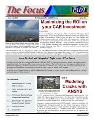
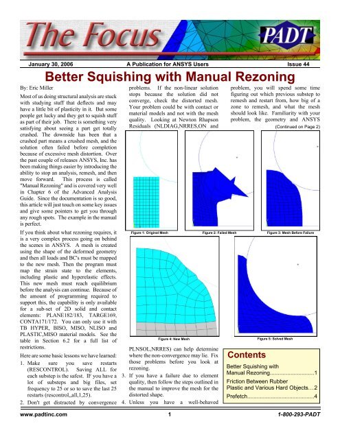
Figure 1: Original Mesh Figure 2: Failed Mesh Figure 3: Mesh Before Failure<br />
Figure 4: New Mesh<br />
Figure 5: Solved Mesh<br />
<strong>Better</strong> <strong>Squishing</strong> <strong>with</strong><br />
<strong>Manual</strong> <strong>Rezoning</strong>............................1<br />
Friction Between Rubber<br />
Plastic and Various Hard Objects...2<br />
Prefetch...........................................4<br />
www.padtinc.com 1 1-800-293-<strong>PADT</strong>
January 30,2006 The Focus Issue 44<br />
meshing options really pay off here.<br />
5. If you try out a given mesh at a given<br />
substep (using MAPSOLVE) and the<br />
mapping does not converge, keep<br />
backing up to earlier substesps. Try this<br />
on the example problem in the manual.<br />
If you start <strong>with</strong> iteration 10, you will<br />
find that it doesn't converge on the<br />
MAPSOLVE. Iteration 8 does. The<br />
example in the manual uses iteration 7.<br />
6. Once you have done a rezone on a given<br />
substep and tried it out, the RST file gets<br />
truncated. So if you fail on iteration<br />
1,125 don't try and rezone on 1,100 first.<br />
If that was too early you can't recover<br />
and go back (unless you saved a copy of<br />
your result and restart files).<br />
7. Use APDL scripts to simplify the task.<br />
Once established you just change one or<br />
two values in it (like the iteration and<br />
mesh parameters) and rerun it. One<br />
thing to note though, don't put a SOLVE<br />
after the MAPSOLVE in the same<br />
macro. If the MAPSOLVE fails<br />
ANSYS will just keep on running and<br />
will do a restart on your original mesh.<br />
8. Don't be afraid of changing MOPT<br />
options. The alternative meshers<br />
available through this command may<br />
give better meshes for nasty geometry,<br />
and MOPT,AORDER,ON greatly helps<br />
mesh areas of disparate size<br />
9. To get better control, look at meshing<br />
multiple zones rather than one zone.<br />
10. We have found that creating a plot that<br />
shows the new mesh surounded by the<br />
old is useful. Here are the APDL<br />
commands we stick on our scripts where<br />
you would normally just put the amesh<br />
command.<br />
esel,u,,,all !Unselect all the elements<br />
amesh,2 !Mesh the area made from the<br />
!old elements (aremesh,-1)<br />
eplot !Plot the new mesh<br />
/noerase !Turn off erase<br />
/user !Set zoom and focus based<br />
!upon new elements<br />
esel,invert !Select everything but the<br />
! new elements<br />
/num,-1 !Turn off colors and numbers<br />
Eplot !Plot old elements<br />
/erase !Turn erase back on<br />
/num, !Set numbering back<br />
11. When viewing the distorted geometry,<br />
make sure the distortion scale is set to<br />
one (/DSCALE,,1), which is the default.<br />
Also, look at the geometry <strong>with</strong> PLDISP<br />
which shows the mesh shape, or if you<br />
are plotting contours, issue a /EDGE,1,1<br />
to see the mesh. We also find that<br />
setting the colors to reverse video<br />
(PltCtls->Style->Colors->Reverse<br />
Video) is a better way to view the mesh.<br />
Beyond these recommendations, you need<br />
the same level of ANSYS user experience<br />
and common sense that is required for any<br />
complex non-linear analysis. With this<br />
capability and some perseverance you can<br />
solve problems that you would never have<br />
even contemplated before.<br />
Typical Rezone Macro<br />
finish<br />
/clear,nostart<br />
/file,RznExample<br />
/show,png<br />
/show,file<br />
/solution<br />
rezone,manual,1,8<br />
remesh,start ! start process<br />
esel,,,,65,128 ! select region to remesh<br />
aremesh,-1 ! create area for new mesh<br />
shpp,modify,11,45 ! control quad shape<br />
shpp,modify,12,45 ! tighter<br />
!------------------------<br />
! Area mesh replaced to mesh and plot<br />
esel,u,,,all !Unselect all the elements<br />
amesh,2 !Mesh the area made from<br />
!the old elements (aremesh,-1)<br />
/show,file !A /show,png was done earlier<br />
eplot !Plot the new mesh<br />
/noerase !Turn off erase<br />
/user !Set view to user<br />
esel,invert !Invert active elements<br />
/num,-1 !Turn off colors/numbers<br />
eplot !Plot old elements<br />
/erase !Turn erase back on<br />
/num, !Turn num/color back on<br />
/show,close !Close plot file<br />
/show,term<br />
!---------------------<br />
esel,all<br />
nsel,all<br />
remesh,fini ! finish remeshing process<br />
mapsolve,50 ! map solutions<br />
/eof ! we prefer to stop here,<br />
!check that the mapsolve<br />
finish ! worked then do the restart<br />
/solution ! restart<br />
antype,,restart<br />
Guest Article:<br />
Friction Between Rubber,<br />
By: Kurt Miller<br />
Axel Products<br />
We are pleased to have another fantastic article<br />
about material property characterization from<br />
Kurt Miller of Axel Products<br />
Friction is the resistance to sliding between<br />
two surfaces in contact when pressed together.<br />
Friction is often described <strong>with</strong> a<br />
single coefficient (COF) which is the sliding<br />
resistance force divided by the normal<br />
force pushing the two surfaces together.<br />
This value is thought to be applicable across<br />
a range of normal forces. It isn’t hard to<br />
find a table on the Internet or in an old<br />
textbook which provides static and dynamic<br />
friction values for various material pairs. It<br />
couldn’t be easier. As long as the analysis at<br />
hand is entirely insensitive to friction values,<br />
we’ll be OK.<br />
Even Despite Leonardo da Vinci’s observations<br />
that his wooden blocks demonstrated<br />
friction values that were insensitive to the<br />
area of contact and the normal force, this is<br />
not often the case <strong>with</strong> plastic, rubber and<br />
various hard surfaces. Changing the normal<br />
pressure from values typical of lightweight<br />
ASTM sled tests to normal pressures typical<br />
in sealing applications can double the COF<br />
and strangely enough in some cases actually<br />
reduce the COF!<br />
Consider a simple microscopic bumps<br />
model (Guillaume Amontons (1663-<br />
1705)). The microscopic bumps and holes<br />
on the two material surfaces touch each<br />
other and the interference between the two<br />
sets of bumps in the direction of movement<br />
causes a frictional force. Changes in the<br />
normal force between the surfaces changes<br />
the nature of the contact and therefore the<br />
Sketch of da Vinci’s Test Apparatus<br />
magnitude of the frictional force. There can<br />
also be complex yet very real molecular<br />
forces between two surfaces but for this<br />
discussion will stay <strong>with</strong>in the microscopic<br />
(Continued on Page 3<br />
Typical Microscopic Bump Profile<br />
www.padtinc.com 2 1-800-293-<strong>PADT</strong>
Plastics and rubbers will soften at elevated<br />
temperatures and stiffen at cold tempera-<br />
January 30,2006 The Focus Issue 44<br />
Test the Right Material<br />
tures. Special attention need to applied in<br />
cases where the material moves through a<br />
glass transition temperature. Naturally, the<br />
friction measurements will change as well.<br />
Low Normal Force Sled Test Apparatus<br />
Typical COF as a Function of Normal Pressure<br />
High Normal Force Test Apparatus<br />
bumps model. It is safe to say that anything<br />
that would alter the material properties of<br />
the microscopic bumps and the nature of the<br />
contact between the two materials will also<br />
alter the frictional forces. So based on this<br />
logic and experience in the lab, here are<br />
some things to get right when measuring<br />
friction values for use in engineering analysis:<br />
This may seem obvious but this needs to be<br />
said. A soft silicone (say, 50 durometer) is<br />
very different than a stiff silicone (say, 75<br />
durometer) and the resulting friction values<br />
will be very different. Stainless steel is<br />
different than bronze. Ideally, the 2 materials<br />
used in the experiment will be the same<br />
materials as in the parts, processed in the<br />
same way.<br />
Get the Surface Finish Right<br />
This can be tricky but the surface finish is<br />
very important. Hard surfaces like steel<br />
need to be machined to a similar roughness<br />
and if possible, in the same direction as the<br />
application. Plastics and rubbers need to<br />
have a similar mold surface as the actual<br />
parts. Glass needs to be cleaned to match<br />
the application.<br />
Achieve a Reasonable Surface Pressure<br />
Changing the normal pressure between the<br />
2 surfaces by 10% or 50% may not have<br />
much effect. However, changing the normal<br />
force by 2 orders of magnitude could<br />
have a dramatic effect. Common ASTM<br />
friction experiments use a lightweight sled<br />
that generates a relatively small normal<br />
pressure between subject materials. For<br />
many applications, this will generate meaningful<br />
values but for compressed elastomer<br />
seals, the normal pressure of interest will be<br />
orders of magnitude higher. In some cases,<br />
coatings intended to reduce friction will<br />
physically break down under high surface<br />
pressure and can generate friction forces<br />
higher than would have been present <strong>with</strong>out<br />
the coating.<br />
Plastic parts that remain in contact for a<br />
long time prior to relative movement may<br />
creep such that the microscopic bumps flow<br />
into each other. This can result in very high<br />
static friction values. This can be approximated<br />
in the laboratory by holding the subject<br />
materials in contact for a day or more at<br />
an elevated temperature prior to testing.<br />
Test Near to the Application Temperature<br />
Achieve a Similar Rate of Relative Movement<br />
Because the stiffness of some materials can<br />
increase <strong>with</strong> rate due to the rate sensitive<br />
properties of one or both, the relative rate of<br />
movement can be important. For most materials,<br />
changing the rate by 50% will have<br />
little effect. However, if the relative velocity<br />
in the application is orders of magnitude<br />
higher or lower than the experiment, there<br />
will likely be a significant error. This isn’t<br />
uncommon in application where high frequency<br />
vibrations cause high relative velocities.<br />
When the static friction is much greater<br />
than the dynamic friction, there is a greater<br />
likelihood of slick-slip behavior resulting in<br />
squeak and itch noises. This behavior is<br />
complex and beyond the scope of this note.<br />
Understand the sensitivity of the analysis<br />
to friction<br />
If getting the exactly right value for friction<br />
is critical to the analysis, then all of the<br />
above factors need to be carefully examined.<br />
If small changes in friction parameters<br />
cause a design to fail then the design may<br />
not be very robust. In real world applications,<br />
surfaces wear, materials deteriorate<br />
and unintended material can contaminate<br />
the surfaces. Small changes in the basics<br />
can cause big frictional force changes.<br />
Understand how friction data that is used<br />
was measured or define experiments to be<br />
done under your defined conditions. If you<br />
have a chance to define your experiment,<br />
specify the materials, the surface finish, the<br />
normal pressure, the temperature and the<br />
rate.<br />
For more information:<br />
At Axel Products we have several instruments<br />
and methods to measure friction.<br />
For more information, download<br />
www.axelproducts.com/downloads/Friction.pdf.<br />
Simpleware converts 3D Images to structural or fluidmeshes. Easy and robust, it may be the<br />
program you have been looking for.<br />
Resources<br />
Looking for a Reliable Rapid Prototyping Vendor? <strong>PADT</strong> has been the Southwest’s leading<br />
RP service provider for over 11 years. Let us quote on your next job.<br />
www.padtinc.com 3 1-800-293-<strong>PADT</strong>
January 30,2006 The Focus Issue 44<br />
We spent some time trying to come up <strong>with</strong><br />
a clever opening to link dogs, pizza, and<br />
fetching into a witty passage that showed<br />
not only how smart we are, but that we also<br />
are hip engineers who like dogs and pizza.<br />
Unfortunately everything sounded a bit contrived<br />
at worst, and silly at best. But who<br />
can back away from a bad joke once halfmade?<br />
Not us… So in the end we offer this<br />
apology for our weak potential as night-club<br />
comics, but still present this useful, if dull, bit<br />
of information that might improve your productivity.<br />
– the Editors of “The Focus”<br />
Ready Spot? ... “Prefetch!”<br />
You arrive home late. Your family has left<br />
you one piece of pizza in a box precariously<br />
close to the edge of the table. You are tired<br />
from trying to get one more non-linear run<br />
in and you accidentally hit the box as you<br />
reach for that last piece. The box catapults<br />
the slice away from the table and it falls in<br />
slow motion to the floor where Freckles,<br />
who is usually your best friend, waits <strong>with</strong><br />
an open mouth to literally wolf it down.<br />
You fall to the floor in a heap of disappointment,<br />
tears running down your face as your<br />
stomach growls in mockery of your lost, but<br />
truly deserved, meal. Filled <strong>with</strong> self-pity,<br />
you wish that you could have fetched, no<br />
wait, “prefetched”, that slice before that<br />
useless piece of fur <strong>with</strong> a mixed breed<br />
heritage named Freckles decided to betray<br />
you. Hmm… “Prefetch.” Well, at least you<br />
have coined a new phrase from this most<br />
disheartening of experiences. But wait,<br />
once again Bill Gates and his minions have<br />
stolen your glory.<br />
Our IT guy, Dave Mastel, recently enlightened<br />
us to a more formal definition relating<br />
to the WinXP Prefetch directory. This directory<br />
is the repository of data about<br />
launched applications and boot files. Windows<br />
OS preloads portions of these files<br />
and programs into memory so that they<br />
launch more quickly. Sounds like a good<br />
idea, unless you make your living running a<br />
[Start] [Run] [Regedit]<br />
Registry Key: HKEY_LOCAL_MACHINE\SYSTEM\CurrentControlSet\Control\Session Manager\Memory Management\PrefetchParameters<br />
Modify/Create the Value Data Type(s) and Value Name(s) as detailed below.<br />
Data Type: DWORD Value // Value Name: EnablePrefetcher<br />
Setting for Value Data: [0 = Disabled / 1 = Application Launch Prefetch / 2 = Boot Prefetch / 3 = Prefetch All]<br />
As a refresher, in many cases one benefits<br />
from specifying the scratch space<br />
size, via the –m argument on ANSYS<br />
startup. The maximum amount of –m<br />
one can specify depends on the<br />
amount of contiguous RAM available.<br />
This varies from computer to computer.<br />
On windows, it typically ranges from<br />
about 1000mb to 1400mb, for computers<br />
<strong>with</strong> up to 3GB ram. Those <strong>with</strong><br />
4GB and the /3GB switch typically get<br />
between 1700mb and 2400 mb. However,<br />
I and others have notices a degradation<br />
in the typical size… it seems to<br />
be solely due to the Prefetch “feature”.<br />
monolithic analysis code that requires large<br />
chunks of contiguous memory.<br />
So, go to C:\Windows\Prefetch and delete<br />
everything you find. (Don’t worry, those<br />
files come back soon enough, so no fears of<br />
“deleting something you need.”) For me, I<br />
boosted from 1200 to 1325 Mb available for<br />
contiguous scratch space. Others have gotten<br />
an even larger improvement.<br />
<strong>Better</strong> still, edit your registry to only<br />
prefetch boot data as shown.<br />
And as for mongrel pre-fetching…next time<br />
jump down and wrest it from its mouth <strong>with</strong><br />
your own maw. It’s the only way they’ll<br />
REALLY respect you.<br />
Upcoming Training Classes<br />
Month Start End # Title Location<br />
Feb '06 6-Feb 8-Feb 104 ANSYS Workbench Simulation<br />
- Intro<br />
9-Feb 9-Feb 105 ANSYS Workbench, Struct<br />
Nonlin<br />
Temp, AZ<br />
Tempe, AZ<br />
13-Feb 15-Feb 101 Intro to ANSYS, Part 1 Irvine, CA<br />
22-Feb 23-Feb 301 Heat Transfer Tempe, AZ<br />
28-Feb 1-Mar 801 ANSYS Customization <strong>with</strong><br />
APDL<br />
Tempe, AZ<br />
Mar '06 6-Mar 8-Mar 101 Introduction to ANSYS, Part I Albq, NM<br />
9-Mar 10-Mar 102 Introduction to ANSYS, Part II Albq., NM<br />
16-Mar 17-Mar 203 Dynamics Tempe, AZ<br />
23-Mar 24-Mar 501 ANSYS/LS-DYNA Irvine, CA<br />
27-Mar 29-Mar 902 Multiphysics Sim. for MEMS Tempe, AZ<br />
Links<br />
News<br />
Ever need to know an undocumented<br />
command. DRD, another ANSYS CP,<br />
has a great write up:<br />
www.drd.com/searchable/techsupport/undocument.html<br />
- ANSYS, Inc. and Matereality Announce<br />
Interoperability<br />
- Harvard Thermal Acquired by ANSYS, Inc.<br />
- <strong>PADT</strong> Offers Classes in Las Vegas<br />
The Focus is a periodic publication of Phoenix Analysis & Design Technologies (<strong>PADT</strong>).<br />
Its goal is to educate and entertain the worldwide ANSYS user community. More information<br />
on this publication can be found at: http://www.padtinc.com/epubs/focus/about<br />
www.padtinc.com 4 1-800-293-<strong>PADT</strong>
January 30,2006 The Focus Issue 44<br />
Be Cool and Know<br />
what Day it Is!<br />
Download the 2006 <strong>PADT</strong><br />
ANSYS Calendar<br />
ANSYS, Inc. has retooled their user group meeting to orient it<br />
towards a more technical event in a larger venue, to accommodate<br />
the expanded content and larger number of partners who<br />
are supporting it.<br />
Join <strong>PADT</strong> for Good Fun and<br />
Great Technology at the 2006<br />
International ANSYS Conference<br />
As an example, some of the seminar topics are:<br />
ANSYS and Trends in High-Performance Computing<br />
Introduction to AUTODYN<br />
Homeland Security Modeling<br />
ANSYS Delivers Unified Meshing<br />
Modeling <strong>with</strong> Scan Data<br />
Drive Innovation and Quality <strong>with</strong> ANSYS: Design for Six Sigma<br />
ANSYS Advanced Implicit FSI Technology<br />
Advanced Mechanical Capabilities in ANSYS Workbench<br />
Element Technology and Composites<br />
Turbo Systems - Integrated Turbomachinery Design and Analysis<br />
Predicting Fatigue Life <strong>with</strong> ANSYS Workbench<br />
ANSYS CFX Overview and Update<br />
www.padtinc.com 5 1-800-293-<strong>PADT</strong>