Installation guide - Paramount Pools
Installation guide - Paramount Pools
Installation guide - Paramount Pools

Create successful ePaper yourself
Turn your PDF publications into a flip-book with our unique Google optimized e-Paper software.
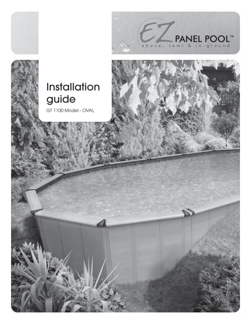
<strong>Installation</strong><br />
<strong>guide</strong><br />
GT 1100 Model - OVAL
WARNING<br />
WARNING<br />
THIS POOL IS NOT DESIGNED FOR DIVING OR JUMPING.<br />
DANGEROUS INJURY CAN RESULT - SHALLOW WATER!!!<br />
Follow All Safety and Maintenance Instructions<br />
Your pool is designed for years of pleasurable, safe family fun. But, when<br />
used incorrectly, a swimming pool can be dangerous. To insure your<br />
pool is used safely you must observe the following safety precautions:<br />
Do not dive! - Do not jump! - No rough play! - No running or pushing!<br />
Do not walk on the top ledge. It can be slippery and is not a walkway.<br />
Be sure to install all safety labels provided with your pool according<br />
to the instructions.<br />
Keep a safety rope 1/4” by 50’with a flotation buoy with an outside<br />
diameter of 15”. Have accessible in a prominent area by your pool.<br />
Post near all entrances to pool area a list of telephone numbers of the:<br />
• Nearest available police • Nearest ambulance service<br />
• Nearest available hospital • Nearest available fire department<br />
• Nearest available physician • Nearest available rescue unit<br />
• 911 emergency number if available<br />
Provide fencing or enclosure which is independent of the house as<br />
a closure around the entire pool area. The fencing must be made of<br />
durable material, a minimum of 4’ in height from ground level and with<br />
closures with self-latching locks, to make pool inaccessible to toddlers<br />
and uninvited guests. Make sure gate is always closed. Be sure to follow<br />
local building code requirements for load capacity and fencing if<br />
using an aftermarket or homebuilt deck. You must make sure all fencing<br />
and barriers are in working order so that pool is always protected.<br />
Check with your local municipality for any special laws in your area.<br />
Never drink alcoholic beverages or use any intoxicants which could<br />
hinder your judgment and reflexes.<br />
Never use pool alone. All children must be supervised continuously.<br />
Do not use pool if bottom is not clearly visible: At night, sufficient lighting<br />
must be available. It is solely the pool owner’s responsibility to<br />
provide adequate lighting for pool bottom, safety signs and walkways,<br />
which exceeds minimum standards of the IES of North America.<br />
Do not climb, stand or sit on any pool structure or the filter system.<br />
Components such as the filtration system, pumps and heater must be<br />
positioned so as to prevent their being used as a means of access to<br />
the pool by young children.<br />
Be sure that all toys, chairs and tables or similar objects that a young<br />
child could climb on be at least 4’ from pool.<br />
Do not use pool during electrical or rain storms.<br />
See available Association of Pool & Spa Professional (APSP)<br />
publications for more tips on pool safety.<br />
IMPORTANT NOTICE! READ BEFORE INSTALLATION.<br />
WARNING<br />
DO NOT AFFIX ANY OTHER<br />
PRODUCTS MADE BY<br />
OTHERS TO YOUR POOL<br />
SUCH AS, BUT NOT LIMITED<br />
TO, DECKS AND SLIDES!<br />
ENCLOSED IN THE FRAME CARTON<br />
IS AN ENVELOPE CONTAINING<br />
SAFETY STICKERS, WHICH MUST BE<br />
INSTALLED AS PER THE FOLLOWING<br />
INSTRUCTIONS. FAILURE TO PROP-<br />
ERLY INSTALL WARNING LABELS<br />
WILL VOID WARRANTY. FAILURE TO<br />
MOUNT THESE SAFETY LABELS MAY<br />
SUBJECT YOU TO SUBSTANTIAL LI-<br />
ABILITY IN CASE OF INJURY.<br />
NO DIVING - NO JUMPING<br />
SHALLOW WATER<br />
DIVING OR JUMPING MAY CAUSE DEATH<br />
OR PERMANENT INJURY<br />
SIGN MUST BE PLACED ON THE<br />
WALL, NEXT TO THE POOL ENTRY.<br />
THESE WARNINGS ARE NOT<br />
TO BE REMOVED UNDER ANY<br />
CIRCUMSTANCES! IF THEY<br />
BECOME DISCOLORED OR<br />
FALL OFF, PLEASE REQUEST<br />
REPLACEMENTS, WHICH WILL<br />
BE SENT AT NO CHARGE.<br />
NO DIVING - NO JUMPING<br />
SHALLOW WATER<br />
SIGN TO BE PLACED ON THE<br />
INSIDE LIP OF THE TOP LEDGE.<br />
1920596 Rev. 0<br />
2
INTRODUCTION<br />
CONGRATULATIONS ON BECOMING THE OWNER OF a NEW SWIMMING POOL.<br />
THESE are INSTRUCTIONS FOR INSTALLING YOUR SWIMMING POOL.<br />
THE FOLLOWING are SOME HELPFUL HINTS THAT YOU SHOULD TAKE INTO<br />
consideration BEFORE INSTALLING YOUR POOL.<br />
1.<br />
Read through the entire instruction booklet before you begin. This will enable you to find out exactly what<br />
is involved with installing your swimming pool before you begin.<br />
2.<br />
DO NOT ATTEMPT INSTALLATION IN WINDY OR GUSTY WEATHER. This will not only make installation more<br />
difficult, it may result in damage to your pool before it is completely installed.<br />
3.<br />
Although we have broken down the installation into many simple steps, you will probably find that steps 1<br />
to 4 will be the most labor-intensive and time-consuming. Once you have completed those four steps you<br />
should find that the rest of the installation moves along much more quickly.<br />
4.<br />
Please be sure to review all safety material and local codes before beginning your installation. There<br />
is a yellow safety envelope packed with your pool. This envelope contains safety material and warning<br />
stickers to be placed on your pool. If you are missing any of these items please contact your dealer or<br />
the factory to obtain it. The warranty is void if all safety precautions are not followed.<br />
5.<br />
In the event that you need to make a warranty claim, it is important to know the size and model of your<br />
swimming pool in order to expedite the handling of your claim. Please fill in the information below and<br />
keep for your records. All of this information can be found on the labels attached to the cartons your<br />
pool is packed in.<br />
POOL MODEL:<br />
SIZE OF POOL:<br />
DATE OF PURCHASE:<br />
LINER MODEL:<br />
6.<br />
Make sure you have the necessary tools and materials before beginning your installation. Below is a list of<br />
the tools and materials needed.<br />
— Shovel<br />
— Carpenter’s level and/or transit (Optional)<br />
— Tape measure<br />
— Patio Blocks (2” x 8” x 16”)<br />
— Phillips head screwdriver<br />
— Box cutter (Razor blade)<br />
— Duct tape<br />
— Tamp<br />
— Sand<br />
— Wrench<br />
— Filter<br />
— Skimmer/Return fitting<br />
3
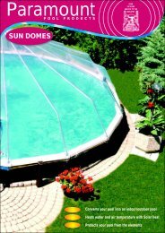
POOL<br />
Your oval EZpanel pool comes in various configurations and sizes.<br />
Make sure you follow the right installation steps.<br />
Your POOl CAn be:<br />
- above ground<br />
- semi-inground<br />
- in ground<br />
The oval structuRAl system CAn be with:<br />
- straps (with or without concrete collar)<br />
- brace (with concrete collar)<br />
The extERIOR finISh COuld be:<br />
- dressed - decorative panels / top ledges<br />
- raw - no decorative panels / top ledegs<br />
EZ Panel Pool Chart of <strong>Installation</strong> Options and Restrictions<br />
Above GROund<br />
The pool can be installed above the ground in round, oval, and rectangle.<br />
PARt way in the GROund with StRAPS<br />
33” or less in the ground: Round, Oval with straps, Rectangle with straps, No concrete collar.<br />
All the way in GROund with StRAPS<br />
33” or more in the ground: Round, Oval with straps, Rectangle with straps, must have concrete<br />
collar<br />
PARt way in the GROund with no StRAPS<br />
33” or less in the ground: Oval with no straps, Rectangle with no straps, not allowed.<br />
All the way in GROund with no StRAPS<br />
36” or more in the ground: Oval with no straps, Rectangle with no straps, must have concrete<br />
collar<br />
WARNING: Don’t use concrete containing calcium chloride.<br />
Panel TyPE<br />
The EZ Panel pool is offered with 2 panel options. The 1 sided aluminum panel option can<br />
be used up to a depth of 33”. Below 33” the pool must be built with the 2 sided aluminum<br />
panel option.<br />
Backfilling REStRICtIOns<br />
When adding water or backfilling a pool there cannot be more than a 3” difference between<br />
the height of the water and the height of the back-fill.<br />
SOIl ConditIOns<br />
All of the Pool <strong>Installation</strong> instructions referred to herein, and elsewhere, are based upon<br />
calculations with respect to the insitu soil mechanics, of the installed swimming pool, viz “all<br />
placed subsoils and backfill, must be clean, dry, drained, granular soils – free of any debris<br />
or deliterious matter – moderately compacted in place.”<br />
4
LEVELS<br />
52''<br />
52''<br />
33'' Max.<br />
in soil<br />
Single Sided Above Ground Panel<br />
Round or Curved end of Oval<br />
Single Sided Semi Inground Panel<br />
Round or Curved end of Oval<br />
Greater than<br />
33’’ in soil<br />
52''<br />
9''<br />
Concrete<br />
28''<br />
Double Sided Inground Panel<br />
Round or Curved end of Oval<br />
52''<br />
52''<br />
33'' Max.<br />
in soil<br />
Single Sided Above Ground Panel with Straps<br />
Rectangle or Straight side of the Oval<br />
Single Sided Semi Inground Panel with Straps<br />
Rectangle or Straight side of the Oval<br />
52''<br />
Greater than<br />
33'' in soil<br />
52''<br />
Greater than<br />
36'' in soil<br />
9''<br />
9''<br />
Concrete<br />
Concrete<br />
28" 28"<br />
Double Sided Inground Panel with Straps<br />
Rectangle or Straight side of the Oval<br />
Double Sided Inground Panel with Braces<br />
Rectangle or Straight side of the Oval<br />
5
PARTS LIST - OVAL<br />
REF. PART NAME<br />
POOL SIZES (IN FEET)<br />
12 x 17 12 x 22 12 x 26 12 x 30 15 x 20 15 x 24 15 x 28 15 x 32 17 x 31 17 x 35 17 x 39<br />
1<br />
Panel<br />
11<br />
13<br />
15<br />
17<br />
13<br />
15<br />
17<br />
19<br />
19<br />
21<br />
23<br />
2<br />
Skimmer<br />
Panel<br />
1<br />
1<br />
1<br />
1<br />
1<br />
1<br />
1<br />
1<br />
1<br />
1<br />
1<br />
3<br />
Rod<br />
12<br />
14<br />
16<br />
18<br />
14<br />
16<br />
18<br />
20<br />
20<br />
22<br />
24<br />
4<br />
Straight<br />
Diameter<br />
Lock<br />
-<br />
2<br />
4<br />
6<br />
-<br />
2<br />
4<br />
6<br />
4<br />
6<br />
8<br />
Width 5/8”<br />
Diameter<br />
Radius Lock 12’<br />
5<br />
(straight to round<br />
section)<br />
4<br />
4<br />
4<br />
4<br />
-<br />
-<br />
-<br />
-<br />
-<br />
-<br />
-<br />
Width 1”<br />
6<br />
Diameter<br />
Radius Lock 12’<br />
(round section)<br />
8<br />
8<br />
8<br />
8<br />
-<br />
-<br />
-<br />
-<br />
-<br />
-<br />
-<br />
Width 2-1/16”<br />
7<br />
Diameter<br />
Radius Lock 15’<br />
(straight to<br />
round section)<br />
-<br />
-<br />
-<br />
-<br />
4<br />
4<br />
4<br />
4<br />
-<br />
-<br />
-<br />
Width 1-1/4”<br />
8<br />
Diameter<br />
Radius Lock 15’<br />
(round section)<br />
-<br />
-<br />
-<br />
-<br />
10<br />
10<br />
10<br />
10<br />
-<br />
-<br />
-<br />
Width 1-3/4”<br />
9<br />
Diameter<br />
Radius Lock 17’<br />
(straight to<br />
round section)<br />
-<br />
-<br />
-<br />
-<br />
-<br />
-<br />
-<br />
-<br />
4<br />
4<br />
4<br />
Width 1”<br />
10<br />
Diameter<br />
Radius Lock 17’<br />
(round section)<br />
-<br />
-<br />
-<br />
-<br />
-<br />
-<br />
-<br />
-<br />
12<br />
12<br />
12<br />
Width 1-5/8”<br />
6
PARTS LIST - OVAL<br />
REF. PART NAME<br />
POOL SIZES (IN FEET)<br />
12 x 17 12 x 22 12 x 26 12 x 30 15 x 20 15 x 24 15 x 28 15 x 32 17 x 31 17 x 35 17 x 39<br />
11<br />
Cosmetic<br />
Panel<br />
Retainer<br />
46<br />
54<br />
62<br />
70<br />
54<br />
62<br />
70<br />
78<br />
78<br />
86<br />
94<br />
(4 per panel)<br />
12<br />
Small<br />
Cosmetic<br />
Panel<br />
Retainer<br />
2<br />
2<br />
2<br />
2<br />
2<br />
2<br />
2<br />
2<br />
2<br />
2<br />
2<br />
(skimmer panel)<br />
13<br />
Cosmetic<br />
Panel<br />
(3 per panel)<br />
33<br />
39<br />
45<br />
51<br />
39<br />
45<br />
51<br />
57<br />
57<br />
63<br />
69<br />
14<br />
Bottom<br />
Cosmetic<br />
Panel<br />
3<br />
3<br />
3<br />
3<br />
3<br />
3<br />
3<br />
3<br />
3<br />
3<br />
3<br />
(skimmer section)<br />
15<br />
Ledge<br />
Union<br />
(left)<br />
16<br />
20<br />
24<br />
28<br />
18<br />
22<br />
26<br />
30<br />
28<br />
32<br />
36<br />
16<br />
Ledge<br />
Union<br />
(right)<br />
16<br />
20<br />
24<br />
28<br />
18<br />
22<br />
26<br />
30<br />
28<br />
32<br />
36<br />
17<br />
Top<br />
Ledge<br />
12<br />
14<br />
16<br />
18<br />
14<br />
16<br />
18<br />
20<br />
20<br />
22<br />
24<br />
18<br />
Small<br />
Top<br />
Ledge<br />
4<br />
6 8 10 4 6 8 10 8 10 12<br />
19<br />
Ledge<br />
Cover<br />
(round section)<br />
8<br />
8<br />
8<br />
8<br />
10<br />
10<br />
10<br />
10<br />
12<br />
12<br />
12<br />
20<br />
Ledge<br />
Cover<br />
(straight section)<br />
4<br />
6<br />
8<br />
10<br />
4<br />
6<br />
8<br />
10<br />
8<br />
10<br />
12<br />
7
PARTS LIST - OVAL<br />
REF. PART NAME<br />
POOL SIZES (IN FEET)<br />
12 x 17 12 x 22 12 x 26 12 x 30 15 x 20 15 x 24 15 x 28 15 x 32 17 x 31 17 x 35 17 x 39<br />
21 Post<br />
Union<br />
4<br />
6 8 10 4 6 8 10 8 10 12<br />
22<br />
Plastic<br />
Sleeve<br />
4<br />
6 8 10 4 6 8 10 8 10 12<br />
23<br />
Straight Union<br />
Post Resin<br />
Decorative<br />
Panel<br />
-<br />
2<br />
4<br />
6<br />
-<br />
2<br />
4<br />
6<br />
4<br />
6<br />
8<br />
24<br />
Corner<br />
Oval Union<br />
Post Resin<br />
Decorative<br />
Panel<br />
4<br />
4<br />
4<br />
4<br />
4<br />
4<br />
4<br />
4<br />
4<br />
4<br />
4<br />
25<br />
Curved<br />
Resin<br />
Decorative<br />
Panel<br />
8<br />
8<br />
8<br />
8<br />
10<br />
10<br />
10<br />
10<br />
12<br />
12<br />
12<br />
26<br />
Hardware<br />
Bag<br />
1<br />
1 1 1 1 1 1 1 1 1 1<br />
8
PARTS LIST - OVAL<br />
SPECIFIC TO STRAPS SYSTEM “T”<br />
27<br />
Steel<br />
“T”<br />
Support<br />
4<br />
6<br />
8<br />
10<br />
4<br />
6<br />
8<br />
10<br />
8<br />
10<br />
12<br />
28<br />
Universal<br />
Steel<br />
Strap<br />
6<br />
9<br />
12<br />
15<br />
8<br />
12<br />
16<br />
20<br />
16<br />
20<br />
24<br />
29<br />
Pressure<br />
Plate<br />
2<br />
4<br />
6<br />
8<br />
2<br />
4<br />
6<br />
8<br />
6<br />
8<br />
10<br />
9
PARTS LIST - OVAL<br />
SPECIFIC TO BRACE SYSTEM “L”<br />
30<br />
Turnbuckle<br />
5/8-11<br />
4<br />
6<br />
8<br />
10<br />
4<br />
6<br />
8<br />
10<br />
8<br />
10<br />
12<br />
31<br />
Angle<br />
Turnbuckle<br />
4<br />
6<br />
8<br />
10<br />
4<br />
6<br />
8<br />
10<br />
8<br />
10<br />
12<br />
32<br />
“L’’ Vertical<br />
Post<br />
4<br />
6<br />
8<br />
10<br />
4<br />
6<br />
8<br />
10<br />
8<br />
10<br />
12<br />
33<br />
Rebar<br />
4<br />
6<br />
8<br />
10<br />
4<br />
6<br />
8<br />
10<br />
8<br />
10<br />
12<br />
*not included<br />
34<br />
Base<br />
Rectangular<br />
Tube<br />
4<br />
6<br />
8<br />
10<br />
4<br />
6<br />
8<br />
10<br />
8<br />
10<br />
12<br />
35<br />
End<br />
Fitting<br />
Turnbuckle<br />
8<br />
12<br />
16<br />
20<br />
8<br />
12<br />
16<br />
20<br />
16<br />
20<br />
24<br />
10
EXPLODED VIEW - OVAL<br />
15/16<br />
19<br />
18<br />
20<br />
17<br />
5 to 10<br />
4<br />
5 to 10<br />
14<br />
13<br />
12<br />
3<br />
23/24/25<br />
11<br />
11<br />
2<br />
1<br />
21<br />
11
EXPLODED VIEW - OVAL<br />
BRACE SYSTEM “L”<br />
21<br />
35<br />
30<br />
33<br />
22<br />
32<br />
31<br />
35 34<br />
STRAPS SYSTEM “T”<br />
22<br />
28<br />
27<br />
29<br />
12
POOL AREA DIMENSIONS<br />
IMPORTANT INFORMATION PRIOR TO INSTALLATION<br />
ALL DIAGONAL DIMENSIONS ARE TAKEN AT THE PIVOT POINT WHERE THE PANELS<br />
START GOING INTO THE ROUND SECTION - SEE VISUAL.<br />
13
POOL AREA DIMENSIONS<br />
12’ x 17’<br />
12’ x 22’<br />
14
POOL AREA DIMENSIONS<br />
12’ x 26’<br />
12’ x 30’<br />
15
POOL AREA DIMENSIONS<br />
15’ x 20’<br />
15’ x 24’<br />
16
POOL AREA DIMENSIONS<br />
15’ x 28’<br />
15’ x 32’<br />
17
POOL AREA DIMENSIONS<br />
17’ x 31’<br />
17’ x 35’<br />
18
POOL AREA DIMENSIONS<br />
17’ x 39’<br />
19
INSTALLATION<br />
STEP 1<br />
When you choose the appropriate site for your pool,<br />
make sure you allow for the distance between the pool<br />
and property line as required by law in your municipality.<br />
Do not locate pool over underground lines, septic<br />
tanks, under electrical lines, near hazardous structures,<br />
or out of local code restrictions. It is essential that the<br />
area selected for your pool has a level and firm base.<br />
Do not assemble your pool on asphalt, tar or oil base<br />
surfaces. Avoid areas with sharp objects, or ground<br />
treated with weed killer or other chemicals. Also avoid<br />
areas where nut grass, Bermuda grass or bamboo grass<br />
grows, as they can grow through your liner. Do not<br />
place components such as filters, pumps, and heaters<br />
in a way that they can be used as a means of access<br />
to pool by young children. Be sure to follow all local<br />
building codes and obtain all building permits required<br />
for your area.<br />
It is essential to plan the location of the skimmer and<br />
return plumbing, at this point. Also plan the location<br />
of pool views, pool entrance, decks, fences, privacy<br />
shields, sun path, breeze direction, shrubs, filters, pumps,<br />
and in-ground drainage.<br />
BE SURE TO AVOID<br />
- All electrical wires<br />
- All gas lines<br />
- Septic tanks<br />
- Cesspools<br />
- Dry wells<br />
- Tree roots/stumps<br />
- Buried debris (trees,<br />
building material, etc.)<br />
- Sudden slopes within 6’<br />
of pool area<br />
20
INSTALLATION<br />
STEP 2<br />
D<br />
E<br />
E<br />
B<br />
B<br />
E<br />
C<br />
A<br />
C<br />
ILLUSTRATION A<br />
Dimension A b C d E<br />
12’ x 17’ 14’10’’ 5’9-3/4’’ 6’3-1/2’’ 4’5-1/16’’ 6’’ / 18’’<br />
12’ x 22’ 14’10’’ 5’9-3/4’’ 10’6-5/8’’ 8’8-1/8’’ 6’’ / 18’’<br />
12’ x 26’ 14’10’’ 5’9-3/4’’ 14’9-3/8’’ 12’11-1/4’’ 6’’ / 18’’<br />
12’ x 30’ 14’10’’ 5’9-3/4’’ 19’0-1/2’’ 17’2-1/4’’ 6’’ / 18’’<br />
15’ x 20’ 18’8-1/8’’ 7’8’’ 4’3-1/16’’ 4’5-1/16’’ 6’’ / 18’’’<br />
15’ x 24’ 18’8-1/8’’ 7’8’’ 8’6-1/8’’ 8’8-1/8’’ 6’’ / 18’’’<br />
15’ x 28’ 18’8-1/8’’ 7’8’’ 12’9-1/4’’ 12’11-1/4’’ 6’’ / 18’’<br />
15’ x 32’ 18’8-1/8’’ 7’8’’ 17’0-1/4’’ 17’2-1/4’’ 6’’ / 18’’<br />
17’ x 22’ 20’7-3/16’’ 8’7-5/8’’ 5’2-1/8’’ 4’5-1/16’’ 6’’ / 18’’<br />
17’ x 26’ 20’7-3/16’’ 8’7-5/8’’ 9’5-3/16’’ 8’8-1/8’’ 6’’ / 18’’<br />
17’ x 31’ 20’7-3/16’’ 8’7-5/8’’ 13’8-1/4’’ 12’11-1/4’’ 6’’ / 18’’<br />
17’ x 35’ 20’7-3/16’’ 8’7-5/8’’ 17’11-3/8’’ 17’2-1/4’’ 6’’ / 18’’’<br />
12’ x 39’ 20’7-3/16’’ 8’7-5/8’’ 22’2’’ 21’5-3/16’’ 6’’ / 18’’<br />
Once you have selected your site, trace the outside<br />
perimeter of your pool on the ground using spray paint<br />
in accordance with the diagram at the top of this<br />
page.<br />
The junction between panels should be over the<br />
half circle.<br />
The length of the lines you trace will vary according the<br />
overall dimensions of your pool. Find your pool dimensions<br />
on the above chart and use the letters (A, B, C, D,<br />
E) from the diagrams to determine the correct lengths<br />
of the lines you will trace<br />
Draw the centerline first (C). Each end of the centerline<br />
becomes the center of your half circle line.<br />
Draw a half circle on the ground, on each end, as a<br />
<strong>guide</strong>line for the position of the panels (you should add<br />
6" to the pool radius for an abvoveground pool, 18" for<br />
a semi-inground or inground).<br />
21
INSTALLATION<br />
STEP 3<br />
RADIUS + 8" ABOVEGROUND<br />
+ 18" INGROUND / SEMI-INGROUND<br />
B<br />
6”<br />
ABOVEGROUND<br />
18”<br />
INGROUND OR<br />
SEMI-INGROUND<br />
Remove the sod from the area you have just outlined.<br />
You must add 6” to the B dimension listed at step 2 to<br />
leave space for the panels for an aboveground pool.<br />
When installing the pool inground or semi-inground,<br />
add 18” to the “B” dimension listed at step 2 to leave<br />
space for assembly. Dig to the desired depth - See<br />
page 5 for more detailed information on installation<br />
options.<br />
Remove all debris (rocks, roots etc.) using a rake.<br />
22
INSTALLATION<br />
STEP 4<br />
ABOVEGROUND INSTALLATION<br />
Dig the areas where the steel “T” or “L” supports are to<br />
be installed. Dig to a depth of 3 inches. Refer to the<br />
drawings on pages 14 to 19 to find out the exact “T” or<br />
“L” support position for your pool dimension.<br />
Take material such as stone dust or fine mortar that can<br />
form a solid, permanent base and deposit this material<br />
around the rim of the basin.<br />
The material used should be spread around the perimeter<br />
of the pool to a width of 24’’ and a thickness<br />
of 2’’. Level the material with a straight wooden plank<br />
and a level. Wet and pack down the stone dust into a<br />
smooth, level mass.<br />
23
The FOllOWING SECTION<br />
DESCRIBES HOW TO IN-<br />
STAll YOU EZPANEL POOL<br />
WIth A STRAP “T” STRUCtuRE.<br />
GO TO STEP 15 FOR A “L”<br />
BRACE OVAL SYSTEM<br />
24
“T” ASSEMBLY - OVAL<br />
STEP 5<br />
Start with the straight section of the pool by installing<br />
the universal steel strap onto the steel “T” support<br />
using 2 screw pins 1/4-20 1/2’’ long, with serrated<br />
nuts 1/4-20.<br />
Use the two holes side by side.<br />
Insert and level a concrete slab of approximately<br />
8” x 16” x 2” under each steel “T” support.<br />
25
“T” ASSEMBLY - OVAL<br />
STEP 6<br />
Attach all of the universal steel straps together at each<br />
joint using 3 screw pins 1/4-20 1/2’’ long, with serrated<br />
nuts 1/4-20.<br />
Use the 3 holes that are in line.<br />
Refer to the strap layout on next page based on your<br />
pool dimensions.<br />
26
“T” ASSEMBLY - OVAL<br />
STEP 6B<br />
Universal STEEL Strap Layouts<br />
12’<br />
by any length<br />
15’<br />
by any length<br />
17’<br />
by any length<br />
27
“T” ASSEMBLY - OVAL<br />
STEP 7<br />
Place a pressure plate on the “T” support, but do not<br />
screw in. This will enable you to align them correctly.<br />
Make sure the bases of the horizontal sleeves are level<br />
with the surrounding ground.<br />
IMPORTANT<br />
Wait until the panels are installed before fastening the<br />
pressure plates.<br />
Measure the two intersecting axes to ensure that the<br />
two straight sections are parallel.<br />
Screw the pressure plate to the T base using screw AB<br />
Pins # 12 x 0.75 (3 on each side).<br />
28
“T” ASSEMBLY - OVAL<br />
STEP 8<br />
Slide over the “T” the plastic sleeve.<br />
The cut-out (opening) should be toward the outside of<br />
the pool.<br />
29
“T” ASSEMBLY - OVAL<br />
STEP 9<br />
OUTSIDE<br />
POOL<br />
INSIDE<br />
POOL<br />
TOP VIEW<br />
Slide the post union over the “T” (now with the plastic<br />
sleeve).<br />
The hinge detail should be toward the inside of the<br />
pool.<br />
30
“T” ASSEMBLY - OVAL<br />
STEP 10<br />
ILLUSTRATION A<br />
Starting in the straight section of the oval pool, insert a<br />
panel between the union posts and lock them in place<br />
using a rod on each side.<br />
Insert the rod using a mallet. Be careful not to crush the<br />
top part of the panel (see illustration A).<br />
31
“T” ASSEMBLY - OVAL<br />
STEP 11<br />
Straight Diameter Lock<br />
Diameter Radius Lock<br />
(straight to round section)<br />
Diameter Radius Lock<br />
(refer to your pool size)<br />
TOP VIEW<br />
Radius Lock Diameter<br />
(straight to round section)<br />
Radius Lock Diameter<br />
(straight to round section)<br />
Radius Lock Diameter<br />
(straight to round section)<br />
Radius Lock Diameter<br />
(straight to round section)<br />
Make sure that the panels are installed according to<br />
your pool dimension – refer to pages 14 to 19.<br />
Slide in the diameter radius lock corresponding to the<br />
pool size.<br />
There are 3 types of diameter radius locks:<br />
• Diameter Radius Lock - round section<br />
• Diameter Radius Lock - straight to round section<br />
• Straight Diameter Lock - straight section<br />
Refer to illustration above to know where to put each<br />
of them.<br />
Repeat step 10 and 11 for all panels<br />
DIMENSIONS<br />
12x17<br />
12x22<br />
12x26<br />
12x30<br />
15x20<br />
15x24<br />
15x28<br />
15x32<br />
17x31<br />
17x35<br />
17x39<br />
RADIUS LOCK WIDTH<br />
Straight section Transition Round section<br />
5/8’’<br />
5/8’’<br />
5/8’’<br />
5/8’’<br />
5/8’’<br />
5/8’’<br />
5/8’’<br />
5/8’’<br />
5/8’’<br />
5/8’’<br />
5/8’’<br />
1’’<br />
1’’<br />
1’’<br />
1’’<br />
1’’ 1/4<br />
1’’ 1/4<br />
1’’ 1/4<br />
1’’ 1/4<br />
1’’<br />
1’’<br />
1’’<br />
2’’ 1/16<br />
2’’ 1/16<br />
2’’ 1/16<br />
2’’ 1/16<br />
1’’ 3/4<br />
1’’ 3/4<br />
1’’ 3/4<br />
1’’ 3/4<br />
1’’ 5/8<br />
1’’ 5/8<br />
1’’ 5/8<br />
32
“T” ASSEMBLY - OVAL<br />
STEP 12<br />
TOP VIEW<br />
Slide the straight diameter lock where the panels are<br />
lined-up with the union post.<br />
Using pliers, “crimp” the end of the<br />
radius lock to prevent the part to “drop<br />
through” when installed<br />
33
“T” ASSEMBLY - OVAL<br />
STEP 13<br />
Diameter radius lock once installed.<br />
34
“T” ASSEMBLY - OVAL<br />
STEP 14<br />
TOP VIEW<br />
At this point you can tight up the screws holding the<br />
pressure plate to “T” support.<br />
Move to step 27 to continue your installation.<br />
35
THE FOllOWING<br />
SECTION DESCRIBES<br />
HOW TO INSTAll YOUR<br />
EZPANEL POOL WIth A<br />
BRACE SYSTEM (“L”).<br />
36
“L” ASSEMBLY - OVAL<br />
STEP 15<br />
Assemble the “L” vertical post with the base rectangular<br />
tube using a screw hex 5/8-11 x 3,5" long and nut.<br />
The 2 parts should be perpendicular to each other.<br />
37
“L” ASSEMBLY - OVAL<br />
STEP 16<br />
Slide the plastic sleeve over the “L” assembly.<br />
The cut-out (opening) should be toward the outside of<br />
the pool.<br />
38
“L” ASSEMBLY - OVAL<br />
STEP 17<br />
Slide the post union over the “L” assembly (now with the<br />
plastic sleeve).<br />
The hinge detail should be toward the inside of the<br />
pool.<br />
39
“L” ASSEMBLY - OVAL<br />
STEP 18<br />
Install the end fitting turnbuckle using a screw hex 5/8-<br />
11 x 1.5" long and nut on the base rectangular tube.<br />
40
“L” ASSEMBLY - OVAL<br />
STEP 19<br />
Assemble the angle turnbuckle, the turnbuckle and<br />
angle bracket to the end fitting turnbuckle using 4<br />
screws hex 3/8-16 x 1" long and nuts.<br />
41
“L” ASSEMBLY - OVAL<br />
STEP 20<br />
Secure the angle turnbuckle, to the “L” assembly using 2<br />
screw hex drilling 1/4 x 1.5" long.<br />
42
“L” ASSEMBLY - OVAL<br />
STEP 21<br />
carpenter level<br />
turnbuckle<br />
Using a carpenter level, adjust the turnbuckle in order<br />
to have the union post vertical.<br />
43
“L” ASSEMBLY - OVAL<br />
STEP 22<br />
Secure the “L” assembly to the ground by inserting a<br />
rebar* 1/2 (#4) x 12" long through the base rectangular<br />
tube.<br />
* not included<br />
44
“L” ASSEMBLY - OVAL<br />
STEP 23<br />
ILLUSTRATION A<br />
Starting in the straight section of the oval pool, insert a<br />
panel between the union posts and lock them in place<br />
using a rod on each side.<br />
Insert the rod using a mallet. Be careful not to crush the<br />
top part of the panel (see illustration A).<br />
45
“L” ASSEMBLY - OVAL<br />
STEP 24<br />
Straight Diameter Lock<br />
Diameter Radius Lock<br />
(straight to round section)<br />
Diameter Radius Lock<br />
(refer to your pool size)<br />
TOP VIEW<br />
Radius Lock Diameter<br />
(straight to round section)<br />
Radius Lock Diameter<br />
(straight to round section)<br />
Radius Lock Diameter<br />
(straight to round section)<br />
Radius Lock Diameter<br />
(straight to round section)<br />
Make sure that the panels are installed according to<br />
your pool dimension – refer to pages 14 to 19.<br />
Slide in the diameter radius lock corresponding to the<br />
pool size.<br />
There are 3 types of diameter radius locks:<br />
• Diameter Radius Lock - round section<br />
• Diameter Radius Lock - straight to round section<br />
• Straight Diameter Lock - straight section<br />
Refer to illustration above to know where to put each<br />
of them.<br />
DIMENSIONS<br />
12x17<br />
12x22<br />
12x26<br />
12x30<br />
15x20<br />
15x24<br />
15x28<br />
15x32<br />
17x31<br />
17x35<br />
17x39<br />
RADIUS LOCK WIDTH<br />
Straight section Transition Round section<br />
5/8’’<br />
5/8’’<br />
5/8’’<br />
5/8’’<br />
5/8’’<br />
5/8’’<br />
5/8’’<br />
5/8’’<br />
5/8’’<br />
5/8’’<br />
5/8’’<br />
1’’<br />
1’’<br />
1’’<br />
1’’<br />
1’’ 1/4<br />
1’’ 1/4<br />
1’’ 1/4<br />
1’’ 1/4<br />
1’’<br />
1’’<br />
1’’<br />
2’’ 1/16<br />
2’’ 1/16<br />
2’’ 1/16<br />
2’’ 1/16<br />
1’’ 3/4<br />
1’’ 3/4<br />
1’’ 3/4<br />
1’’ 3/4<br />
1’’ 5/8<br />
1’’ 5/8<br />
1’’ 5/8<br />
Repeat step 23 and 24 for all panels.<br />
46
“L” ASSEMBLY - OVAL<br />
STEP 25<br />
TOP VIEW<br />
Slide the straight diameter lock where the panels are<br />
lined-up with the union post.<br />
Using pliers, “crimp” the end of the<br />
radius lock to prevent the part to “drop<br />
through” when installed<br />
47
“L” ASSEMBLY - OVAL<br />
STEP 26<br />
Diameter radius lock once installed.<br />
48
OnCE all PAnels<br />
ARE installed with<br />
“T” OR “L” ASSEmbly,<br />
COntinue installing<br />
your POOl with next<br />
stEPS.<br />
RemembER, the EZ-<br />
PAnel POOl COmES<br />
in vARIOus COnfIGuRAtIOns,<br />
make<br />
suRE you follow the<br />
RIGht installatIOn<br />
stEPS.<br />
49
INSTALLATION<br />
STEP 27<br />
OPtIOnAl<br />
Required for aboveground or semi-inground<br />
installation.<br />
From the top, slide the cosmetic panel retainers into the<br />
vertical grooves on the panel. There are 4 grooves per<br />
panel.<br />
Install the two small cosmetic panel retainers in the<br />
middle of the skimmer panel.<br />
50
INSTALLATION<br />
STEP 28<br />
Corner Resin<br />
Decorative Panel<br />
Straight Decorative<br />
Resin Panel<br />
Corner Oval Decorative<br />
Resin Panel<br />
Curved Decorative<br />
Resin Panel<br />
Cosmetic panels<br />
You have various cosmetic resin panels to cover the<br />
structure and enhance the look of your EZ Panel Pool.<br />
To cover the union post, there are 3 kinds of cosmetic<br />
resin decorative panels; the Straight resin decorative<br />
panels go where the junction is straight (the middle<br />
union posts) and the Corner resin decorative panels go<br />
where the round section meets the straight section (you<br />
have only 4 of these, regardless of the size of your pool).<br />
And finally, the curved decorative panels go where in<br />
the round section. Refer to illustration and chart on next<br />
page.<br />
51
INSTALLATION<br />
STEP 29<br />
Straight side<br />
Corner<br />
Curved<br />
DIMENSIONS<br />
RESIN DECORATIVE PANEL WIDTH<br />
Straight section<br />
CORNER<br />
CURVED section<br />
12x17<br />
12x22<br />
12x26<br />
12x30<br />
15x20<br />
15x24<br />
15x28<br />
15x32<br />
17x31<br />
17x35<br />
17x39<br />
5’’ 1/4<br />
5’’ 1/4<br />
5’’ 1/4<br />
5’’ 1/4<br />
5’’ 1/4<br />
5’’ 1/4<br />
5’’ 1/4<br />
5’’ 1/4<br />
5’’ 1/4<br />
5’’ 1/4<br />
5’’ 1/4<br />
1’’<br />
1’’<br />
1’’<br />
1’’<br />
1’’ 1/4<br />
1’’ 1/4<br />
1’’ 1/4<br />
1’’ 1/4<br />
1’’<br />
1’’<br />
1’’<br />
3’’ 3/8<br />
3’’ 3/8<br />
3’’ 3/8<br />
3’’ 3/8<br />
3’’ 3/8<br />
3’’ 3/8<br />
3’’ 3/8<br />
3’’ 3/8<br />
3’’ 3/8<br />
3’’ 3/8<br />
3’’ 3/8<br />
52
INSTALLATION<br />
STEP 30<br />
OPtIOnAl<br />
Required for aboveground or semi-inground<br />
installation.<br />
From the top, slide the cosmetic panel into the retainer.<br />
There are three cosmetic panels per panel section.<br />
Each cosmetic panel should sit on the base of the<br />
panel.<br />
The skimmer panels are different – see next page.<br />
In case of a semi-inground pool, cut the length of this<br />
part in order to have it in line with the top of the panel.<br />
53
INSTALLATION<br />
STEP 31<br />
Cosmetic retainer panel<br />
Small cosmetic retainer<br />
Bottom<br />
cosmetic<br />
skimmer panel<br />
The cosmetic panels on the skimmer panel are shorter<br />
than the other panels.<br />
From the top, slide the small bottom cosmetic panels<br />
into the small retainer.<br />
Install the skimmer and return accordng to the manufacturer<br />
installation. You don’t need to connect them<br />
yet.<br />
In case of a semi-inground pool, cut the length of the<br />
cosmetic panel and small cosmetic retainer in order to<br />
have them in line with the top panel.<br />
54
INSTALLATION<br />
STEP 32<br />
Final ground level<br />
Self-drilling screws<br />
According to your installation configuration (semiinground<br />
installation), you might have to custom cut<br />
the cosmetic panels.<br />
First backfill the trench left behind the panels.<br />
Slide the cosmetic panels into the retainer until they<br />
cover the aluminum panels. Cut the panels aligned<br />
with the top of the aluminum panels.<br />
Install a self-drilling screw below the panel to prevent<br />
the cosmetic panel to slide down over the years.<br />
55
“L” ASSEMBLY<br />
STEP 33<br />
9”<br />
28”<br />
concrete<br />
Pour a collar of concrete all around the pool at the<br />
base of the panel. Make sure the panel is level.<br />
WARNING: Do not use concrete with calcium chloride.<br />
56
“T” ASSEMBLY<br />
STEP 34<br />
9”<br />
28”<br />
Pour a collar of concrete all around the pool at the<br />
base of the panel. Make sure the panel is level.<br />
WARNING: Do not use concrete with calcium chloride.<br />
57
INSTALLATION<br />
STEP 35<br />
Put three layers of duct tape over all joints.<br />
If you are using foam coves, clip them at the base of<br />
the panel. There should be no gaps between them.<br />
If you don’t have foam coves, use sand instead.<br />
If you are using sand, bank the sand against the wall to<br />
form a cove 15.24 cm high (6”) and 15.24 cm wide (6”)<br />
at ground level. Water the sand to compact it and use<br />
a trowel to spread it evenly.<br />
58
INSTALLATION<br />
STEP 36<br />
EXTERIOR<br />
INTERIOR<br />
Remove your shoes to avoid damaging the base or<br />
tearing the liner. Open the liner box carefully so as not<br />
to damage the liner. Unfold the liner from the center<br />
outwards.<br />
Note: The liner is generally smaller than the support<br />
structure of the pool. It stretches more easily when<br />
warm. For this reason, it is important that the liner be<br />
installed on a warm sunny day.<br />
You can now start installing the liner onto the pool wall.<br />
Use the liner’s vertical seam as a <strong>guide</strong> and make sure<br />
the seam is vertical and perpendicular to the seam<br />
between wall and bottom.<br />
EXTERIOR<br />
We recommend the use of coping lock with the EZ-<br />
Panel pool.<br />
Make sure the seam between wall and bottom sits onto<br />
the cove.<br />
Hang the liner into the molded slot of the panel.<br />
59
INSTALLATION<br />
STEP 37<br />
OPTIONAL:<br />
Required for aboveground or semi-inground installation<br />
Insert the ledge union at the ends of the large and<br />
small top ledge. Use a mallet to push the ledge union<br />
up to the groove in the top ledge.<br />
There is a right and a left version of this part (refer to<br />
parts list).<br />
60
INSTALLATION<br />
STEP 38<br />
A<br />
B<br />
EXTERIOR<br />
EXTERIOR<br />
INTERIOR<br />
INTERIOR<br />
To install the top ledge, center the top ledge over the<br />
panel, with the bulging portion of the top ledge outside<br />
the pool (see illustration A).<br />
Position the top ledge on an angle in order for the hook<br />
inside the top ledge to catch the edge on the top of<br />
the panel.<br />
Once the hook is in position, rotate back the ledge<br />
on top of the panel. Again, make sure the top ledge is<br />
centered on top of the panel.<br />
Using a self-drilling screw Pan Phillips Drilling SST #<br />
10-16x5/8’’, lock the top ledge in place on the panel<br />
on each side.<br />
In the straight section, you will also have to install the<br />
small top ledge (refer to step 24).<br />
EXTERIOR<br />
INTERIOR<br />
61
INSTALLATION<br />
STEP 39<br />
INTERIOR<br />
EXTERIOR<br />
In the straight section and in the straight to round<br />
section of the pool you will have to install small top<br />
ledges. Follow the same procedure as for the large top<br />
ledge (see step 23 on previous page).<br />
62
INSTALLATION<br />
STEP 40<br />
INTERIOR<br />
EXTERIOR<br />
OPTIONAL:<br />
Required for aboveground or semi-inground installation<br />
Hook the ledge cover over the ledge union, starting<br />
from outside the pool and finish inside the pool.<br />
Do the same with the straight ledge cover in the<br />
straight sections.<br />
63
INSTALLATION<br />
STEP 41<br />
Small Top Ledge<br />
Small Top Ledge<br />
Round section<br />
Straight to round section<br />
Straight section<br />
Tuck the ledge cover sides into the groove in the ledge<br />
union.<br />
64
INSTALLATION<br />
STEP 42<br />
This is how your brand new EZ Panel pool should look<br />
like once completed.<br />
There are different installation options:<br />
• Aboveground<br />
• Semi-inground<br />
• Inground<br />
Depending on the installation type selected, some<br />
parts are optional (i.e. cosmetic panels).<br />
65
POOL SAFETY & MAINTENANCE<br />
Important Pool Safety & Maintenance<br />
Keep your pool wall and frame clean. Always wash away any deposits of pool chemicals that land on the frame of<br />
your pool. Wash periodically with a mild soap solution (no abrasives). At least once a year use a clear non-yellowing<br />
household wax on all metal components. Your pool and liner must be inspected regularly for leaks, corrosion, scratches,<br />
and punctures. If any problem is found IMMEDIATE CORRECTIVE ACTION MUST BE TAKEN. Small repairs and punctures<br />
in your liner may be easily repaired using repair kits available at your local dealer. Scratches on your pool wall<br />
and frame must be touched up with anti-rust enamel. Wire brush all rust and add a coat of enamel primer followed<br />
by a coat of color matching paint. Pool water is full of various caustic chemicals, which will corrode metal parts. If any<br />
corrosion is allowed to continue, failure of the pool structure may occur which could result in excessive property damage<br />
as well as bodily harm.<br />
The area around and below the skimmer must be carefully and regularly inspected. If these areas are wet, and<br />
remain wet for any length of time, it usually means there is a small leak. Skimmer/skimmer return gaskets must be<br />
replaced when they become defective. Water must not be permitted to continually run down the wall, if neglected,<br />
the pool will break. If proper skimmer/skimmer return gasket care is not maintained, your warranty will be void!<br />
Be sure to follow all local and state safety regulations when installing any accessory to your pool. Any decks and all<br />
entries must be carefully monitored for safety. Installing any other manufacturer’s deck or slide is strictly forbidden!<br />
Winterizing Your Pool<br />
During the winter your pool is subject to more stress than in the summer, and any breakage that is caused by incorrect<br />
winter procedures is not covered by any warranty with this company.<br />
All of our pools and liners are designed to be left up all winter, but nonetheless are subject to the warranty of the liner<br />
being purchased. Continue to chlorinate and filter until the pool is closed down.<br />
Before closing down your pool for the winter you must make a complete inspection of the pool:<br />
• Check all the connections to make sure everything is tight and in good condition<br />
• Check to see that the liner is snugly held in place over the wall.<br />
• Check for any indication of rust or deterioration in any part.<br />
IF ANY OF THE ABOVE IS FAULTY YOU MUST CORRECT THE SITUATION IMMEDIATELY<br />
Lower the level of water to about one foot below the skimmer intake and return holes. Throughout the winter you must<br />
continually check this level, as it must not reach the skimmer holes at any time during the winter.<br />
During the winter the pool requires the use of an equalizer to allow for the expansion and contraction that occurs<br />
when ice is formed and to hold the cover up. This can be a product manufactured for this express purpose and is<br />
available at your swimming pool dealer.<br />
The use of a winterizing agent will simplify the start-up of your pool next season.<br />
A cover designed for winter use is also recommended to keep pressure on the equalizer so it is forces into the water,<br />
keep dirt out and at the same time, serve as a safety cover.<br />
If your skimmer is supplied with a winter plate and cap you must still follow the same steps as above.<br />
It is essential that no water be allowed to run down the wall for any period of time. If your skimmer did not come with<br />
a winter plate, it is available at a nominal charge from your dealer and it is recommended.<br />
66
WINTER RULES<br />
Important Winter Rules<br />
After your pool has been winterized and all steps carefully followed, the following checks and procedures must be<br />
strictly adhered to during fall, winter and spring seasons.<br />
Your pool warranty will be invalid if the pool has been improperly winterized and the following procedures have not<br />
been strictly followed. <strong>Pools</strong> that have been incorrectly winterized have been known to collapse under the tremendous<br />
pressures exerted by ice and snow.<br />
A pool that is left up during the freezing temperatures must not be allowed to leak. It is not uncommon for a leak to<br />
develop during rigorous summer usage and go undetected. What is thought to be water loss due to evaporation or<br />
spillage may be caused by a small leak. Persistent wet areas around the pool should be inspected. To determine if<br />
your pool is leaking, mark the liner at the water level and closely observe the water level in the pool for a period of<br />
10 - 12 days after the pool is closed for the season. Any rain during this period may compensate for any undetected<br />
water leakage. Therefore, if rain occurs, the observation period must be extended to find any leaks.<br />
Maintain a strict leak inspection schedule throughout fall, winter, and spring months. Spring thawing, which frequently<br />
leads to ground heaving, can be especially dangerous if care is not taken.<br />
Maintain a strict inspection of the inner skimmer housing to see that water is not leaking at the gasket. If the skimmer<br />
was not removed, water should not be allowed to collect in the skimmer housing as the water will freeze and crack<br />
the housing, causing possible damage to the wall.<br />
Should ice, or anything else, cut your pool liner allowing the pool to empty, be sure to release the cover thereby removing<br />
the weight from the top of your pool. Failing to do so can cause your pool to collapse.<br />
Consult your pool dealer for the proper winter chemicals for quick spring start-up.<br />
As the ground freezes and thaws over the course of the winter, the ground sometimes sinks. The liner, with the weight<br />
of the ice and snow on it, may also sink. When this happens, the liner may be pulled out of its coping.<br />
Be sure to pull off all excess snow and ice from the winter cover.<br />
Do not permit ice skating or horseplay during the winter as this can cause pool and liner damage, as well as, serious<br />
injuries.<br />
67