GSM Series
GSM Series
GSM Series
Create successful ePaper yourself
Turn your PDF publications into a flip-book with our unique Google optimized e-Paper software.
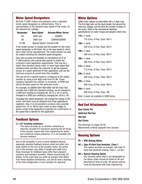
Motor Speed Designators<br />
All Exlar T-LAM motors and actuators carry a standard<br />
motor speed designator as defined below. This is<br />
representative of the standard base speed of the motor, for<br />
the selected bus voltage.<br />
Designator Base Speed Actuator/Motor <strong>Series</strong><br />
-50 5000 rpm <strong>GSM</strong>20<br />
-30 3000 rpm <strong>GSM</strong>30/<strong>GSM</strong>40<br />
01-99 Special Speed, Consult Exlar<br />
If the model number is created and the location for the motor<br />
speed designator is left blank, this is the base speed to which<br />
each motor will be manufactured. The model number can also<br />
be created including this standard speed designator.<br />
Exlar also provides the flexibility to manufacture all of its<br />
T-LAM products with special base speeds to match the<br />
customer’s exact application requirements. This may be a<br />
higher than standard speed motor, or lower base speed than<br />
standard which will allow the customer to get the required<br />
torque, at a speed optimized to their application, and use the<br />
minimum amount of current from their amplifier.<br />
The call out for a special speed is configured in the model<br />
number by using a two digit code from 01-99. These<br />
numbers represent the number, in hundreds, of RPM that<br />
will be the base speed for the particular motor.<br />
For example, an <strong>GSM</strong>30-0301-BSA-EM3-138-30 motor that<br />
normally has a 3000 rpm standard winding, can be changed to<br />
a 3300 rpm winding by changing the -30, to a -33. It can be<br />
changed to a 5000 rpm winding by changing the -30 to a -50.<br />
Changing this speed designator will change the ratings of the<br />
motor, and these must be obtained from Exlar applications<br />
engineers. Also, it is not possible to produce every possible<br />
speed from -01 to -99 for each motor at each voltage so<br />
please contact Exlar applications engineers for confirmation of<br />
the speed that is desired for the application.<br />
Feedback Options<br />
LT = ICT including conditioner<br />
This option provides for an actuator containing an<br />
internally mounted ICT transducer spanning the full stroke<br />
of the actuator. Inquire with Exlar engineering for details<br />
and conditioner output preference. LT is not available with<br />
absolute feedback.<br />
Due to the variability in size of some feedback devices,<br />
especially absolute feedback devices which are often very<br />
large relative to the size of the actuator motor, the actual<br />
size of the actuator may differ in length and width from<br />
these drawings for feedback types other than standard<br />
resolvers and standard encoders. Please consult Exlar for<br />
details. In the event that you order an actuator that differs<br />
from these standard dimensions, you will be sent a drawing<br />
of the final configuration of your actuator for approval.<br />
Motor Options<br />
<strong>GSM</strong> motor options are described with a 3 digit code.<br />
The first digit calls out the stack length, the second the<br />
rated bus voltage, and the third the number of poles of<br />
the motor. Refer to the mechanical/ electrical<br />
specifications for motor torque and actuator rated force.<br />
118 = 1 stack,<br />
115 Vrms, 8 Pole, Class 180 H<br />
138 = 1 stack,<br />
230 Vrms, 8 Pole, Class 180 H<br />
158 = 1 stack,<br />
400 Vrms, 8 Pole, Class 180 H<br />
168 = 1 stack,<br />
460 Vrms, 8 Pole, Class 180 H<br />
218 = 2 stack,<br />
115 Vrms, 8 Pole, Class 180 H<br />
238 = 2 stack,<br />
230 Vrms, 8 Pole, Class 180 H<br />
258 = 2 stack,<br />
400 Vrms, 8 Pole, Class 180 H<br />
268 = 2 stack,<br />
460 Vrms, 8 Pole, Class 180<br />
Note: 3 stack not available in <strong>GSM</strong> <strong>Series</strong><br />
Rod End Attachments<br />
Rear Clevis Pin<br />
Spherical Rod Eye<br />
Rod Eye<br />
Rod Clevis<br />
See drawings on pages 52-53.<br />
Attachments ordered separate from actuator.<br />
Housing Options<br />
P5 = IP65 Sealing Option<br />
HC = Type III Hard Coat Anodized, Class 1<br />
This option provides an actuator with type III<br />
hard coat anodized coating. Class 1, no dye.<br />
XH = Special Housing Option<br />
Any housing option that is not designated by<br />
the above codes should be listed as XH and<br />
described at time of order. All special options<br />
must be discussed with Exlar engineering.<br />
48 Exlar Corporation • 952.368.3434


