6250 Servo Controller User Guide
6250 Servo Controller User Guide
6250 Servo Controller User Guide

Create successful ePaper yourself
Turn your PDF publications into a flip-book with our unique Google optimized e-Paper software.
<strong>6250</strong> <strong>Servo</strong> <strong>Controller</strong><br />
<strong>User</strong> <strong>Guide</strong><br />
Compumotor Division<br />
Parker Hannifin Corporation<br />
p/n 88-013413-01B October 18, 1993
Important <strong>User</strong> Information<br />
To ensure that the equipment described in this user guide, as well as all the equipment connected to and used with it, operates<br />
satisfactorily and safely, all applicable local and national codes that apply to installing and operating the equipment must be<br />
followed. Since codes can vary geographically and can change with time, it is the user's responsibility to identify and comply with<br />
the applicable standards and codes. WARNING: Failure to comply with applicable codes and standards can result in<br />
damage to equipment and/or serious injury to personnel.<br />
Personnel who are to install and operate the equipment should study this user guide and all referenced documentation prior to<br />
installation and/or operation of the equipment.<br />
In no event will the provider of the equipment be liable for any incidental, consequential, or special damages of any kind or nature<br />
whatsoever, including but not limited to lost profits arising from or in any way connected with the use of this user guide or the<br />
equipment.<br />
© Compumotor Division of Parker Hannifin Corporation, 1993<br />
— All Rights Reserved —<br />
The information in this user guide, including any apparatus, methods, techniques, and concepts described herein, are the<br />
proprietary property of Parker Compumotor or its licensors, and may not be copied, disclosed, or used for any purpose not expressly<br />
authorized by the owner thereof.<br />
Since Parker Compumotor constantly strives to improve all of its products, we reserve the right to change this user guide and<br />
equipment mentioned therein at any time without notice.<br />
For assistance in the United States, contact:<br />
Compumotor Division of Parker Hannifin<br />
5500 Business Park Drive<br />
Rohnert Park, CA 94928<br />
Telephone: (800) 358-9070<br />
Fax: (707) 584-8015<br />
For assistance in Europe, contact:<br />
Parker Digiplan<br />
21 Balena Close<br />
Poole, Dorset<br />
England BH17 7DX<br />
Telephone: 0202-690911<br />
Fax: 0202-600820<br />
Compumotor
<strong>6250</strong> <strong>Servo</strong> <strong>Controller</strong> <strong>User</strong> <strong>Guide</strong><br />
Revision B Change Summary<br />
The following is a summary of the primary technical changes to this user guide since the last version was released.<br />
This user guide, p/n 88-013413-01B (released on October 18, 1993), supersedes 88-013413-01A.<br />
Topic Description See Also<br />
<strong>6250</strong>-ANI Analog Input Option<br />
is Released<br />
New Option/Feature: The <strong>6250</strong>-ANI option was released at the same<br />
time this user guide revision B was released. The -ANI option is a ±10V, 14-<br />
bit analog input (with anti-aliasing filter) that is sampled at the servo update<br />
rate (set with the SSFR command). One ANI input terminal is located on each<br />
DRIVE connector. The input value can be transferred to the terminal with the<br />
TANI command, or used in a assignment or comparison operation using the<br />
[ANI] command (e.g., VAR1=1ANI). The TANI and [ANI] commands are<br />
used only by the -ANI option, not the standard <strong>6250</strong>.<br />
Pg. 16, 54 &<br />
68<br />
Analog Voltage Override New Feature (see Program Debugging below) Pg. 67 & 95<br />
Continuous Mode<br />
Clarification: While in the continuous mode (MC1), one of the factors that Pg. 53<br />
can stop motion is if the load trips a switch for a general-purpose input that is<br />
configured as a Kill input (INFNCi-C) or a Stop input (INFNCi-D).<br />
Drive Fault Monitoring Clarification: You must enable the input functions with the INFEN1<br />
command before the drive fault input will be recognized. Also, be sure to set<br />
Pg. 19, 58 &<br />
102<br />
the drive fault level (DRFLVL) appropriately for the drive you are using.<br />
Encoders<br />
Clarification: The Compumotor E Series incremental encoders all have Pg. 12 & 103<br />
the same cable color codes.<br />
Error Handling<br />
Clarification: When an error occurs, the controller will GOTO or GOSUB, Pg. 98<br />
depending on the error condition (an error resolution table is provided).<br />
Homing<br />
Clarification: After the homing operation is successfully completed, the<br />
absolute position register is reset to zero.<br />
Pg. 49<br />
Inputs:<br />
Debounce Time<br />
Power Input (AC)<br />
Program & Command Buffer<br />
Execution Control<br />
Program Debugging<br />
Program Flow Control<br />
New Feature: The INDEB command has been included to allow you to set<br />
the debounce time for the 24 general-purpose programmable inputs and the 2<br />
trigger inputs. The range is 1 - 250 ms, in even increments. The default<br />
debounce time is 4 ms for the 24 inputs, and 25 ms for the trigger inputs.<br />
Correction: The power connection drawing was misleading by stating the<br />
AC input power range was 100 - 120VAC; it is actually 85 - 240VAC.<br />
Clarifications:<br />
Deceleration after a stop input or command—In all variations of the COMEXS<br />
mode, upon receiving a stop input or stop command, motion will decelerate at<br />
the preset AD/ADA value.<br />
Resuming after a stop or pause—In the COMEXR1 & COMEXS1 modes, you can<br />
resume program execution and/or motion with a !C command or the pause/<br />
resume input (INFNCi-E) only after the move in progress is completed.<br />
New Features & Clarifications:<br />
Simulating Analog Input Voltages: (new feature) A new feature called<br />
Analog Voltage Override (enabled with the ANVOEN command and<br />
programmed with the ANVO command) allows you to simulate a voltage on the<br />
analog input channels (input channels 1 - 3 on the JOYSTICK connector).<br />
Programming Error Messages: (clarification) The 6200 can display error<br />
messages and/or a error prompt (?), depending on which error level is<br />
selected with the ERRLVL command. The default error level (ERRLVL4)<br />
displays both the message and the error prompt).<br />
Identifying Bad Commands: (new feature) When the 6200 detects an error<br />
with a command, you can issue the TCMDER command to find out which<br />
command caused the error. This is especially useful when downloading a<br />
program.<br />
New Feature: The JUMP command was added to allow an unconditional<br />
branch to another program and not return. The reason program control does<br />
not return is because all nested IF, WHILE and REPEAT statements, loops,<br />
and subroutines are cleared.<br />
Pg. 58 & 61<br />
Pg. 5<br />
Pg. 86<br />
Pg. 60-61 &<br />
86-87<br />
Pg. 67 & 95<br />
Pg. 97<br />
Pg. 97<br />
Pg. 88
<strong>6250</strong> <strong>User</strong> <strong>Guide</strong> Change Summary (continued)<br />
Programming:<br />
Troubleshooting problems<br />
RMAs<br />
RP240<br />
Software Revision 1.1<br />
Released<br />
Variable Type Conversion<br />
Clarification: In Chapter 7, three resolutions were added to resolve the<br />
following problem situations:<br />
• Start-up program (STARTP) will not run on power up<br />
• Program execution stops at the INFEN1 command<br />
• First time a program is run, the move distances are incorrect, but after<br />
downloading the program a second time the move distances are correct.<br />
Clarification: If you need to return a Compumotor product to affect<br />
repairs or upgrades, be sure to ship it to Suite D at the Rohnert Park<br />
address.<br />
New Features and Clarifications:<br />
Data Read Immediate Mode: (new feature) The DREADI1 command allows<br />
continual input from the RP240 numeric keypad or the function keys (when<br />
used in conjunction with DREAD and/or DREADF). Standard RP240 menus<br />
should not be used in this mode. Data can be read into numeric variables<br />
only. Do not assign the same variable to read numeric and function key data.<br />
Power-up (default) Mode: (clarification) On power up, the 6200 defaults to a<br />
mode in which it controls the RP240 with the menu-driven functions listed on<br />
page 50. To disable this menu, the power-up program (STARTP) must contain<br />
the DCLEARØ command.<br />
This version of the user guide was released at the same time that revision<br />
1.1 of the <strong>6250</strong> software was released.<br />
New Feature: The VCVT( ) command has been added to allow you to<br />
convert between variables (numeric-to-binary and binary-to-numeric).<br />
Pg. 108-109<br />
Pg. 110<br />
Pg. 91<br />
Pg. 70<br />
n/a<br />
Pg. 73
T A B L E O F C O N T E N T S<br />
Overview........................................................................................................... iii<br />
Assumptions.................................................................................................................................iii<br />
Contents of This <strong>User</strong> <strong>Guide</strong>.............................................................................................................iii<br />
Installation Process Overview..........................................................................................................iv<br />
Conventions .................................................................................................................................iv<br />
Chapter 1: Introduction .......................................................................................1<br />
<strong>6250</strong> Description............................................................................................................................1<br />
<strong>6250</strong> Features...............................................................................................................................2<br />
Chapter 2: Getting Started ...................................................................................3<br />
Inspect The Shipment.....................................................................................................................3<br />
Bench Test...................................................................................................................................4<br />
➀ RS-232C Communications...............................................................................................4<br />
➁ Connect Power Cable .....................................................................................................5<br />
➂ Test Procedure .............................................................................................................5<br />
Chapter 3: Installation........................................................................................7<br />
Installation Precautions ..................................................................................................................7<br />
➀ Mount the <strong>6250</strong> .........................................................................................................................8<br />
➁ System Connections..................................................................................................................9<br />
Motor Driver Connections ....................................................................................................9<br />
End-of-Travel Limit Connections ...........................................................................................11<br />
Home Limit Connections......................................................................................................11<br />
Encoder Connections .........................................................................................................12<br />
Auxiliary +5V Output Connection...........................................................................................12<br />
Output and Input Pull-up Connections....................................................................................12<br />
Enable Input Connection .....................................................................................................13<br />
Programmable Inputs & Outputs Connections..........................................................................13<br />
Trigger Input Connections....................................................................................................14<br />
RP240 Front Panel Connections............................................................................................15<br />
Joystick and Analog Input Connections..................................................................................15<br />
ANI Analog Input Connections (<strong>6250</strong>-ANI Option Only)..............................................................16<br />
Extending <strong>6250</strong> System Cables ............................................................................................17<br />
➂ Installation Verification...............................................................................................................17<br />
➃ What's Next?............................................................................................................................19<br />
Chapter 4: <strong>Servo</strong> Tuning ......................................................................................21<br />
<strong>Servo</strong> System Terminology ..............................................................................................................21<br />
<strong>Servo</strong> Tuning Terminology....................................................................................................21<br />
Position Variable Terminology...............................................................................................22<br />
<strong>Servo</strong> Response Terminology...............................................................................................23<br />
6000 Series <strong>Servo</strong> Commands..........................................................................................................25<br />
<strong>Servo</strong> Control Techniques................................................................................................................26<br />
Proportional Feedback Control (SGP).....................................................................................26<br />
Integral Feedback Control (SGI)............................................................................................27<br />
Velocity Feedback Control (SGV)..........................................................................................28<br />
Velocity Feedforward Control (SGVF).....................................................................................28<br />
Acceleration Feedforward Control (SGAF)...............................................................................28<br />
Tuning Setup Procedure..................................................................................................................29<br />
Drive Tuning Procedure (Velocity Drives Only).....................................................................................31<br />
<strong>Controller</strong> Tuning Procedure.............................................................................................................32<br />
Tuning Scenario.............................................................................................................................38<br />
Target Zone (Move Completion Criteria) ..............................................................................................40
Chapter 5: Basic <strong>6250</strong> Features............................................................................. 43<br />
Before You Proceed With This Chapter...............................................................................................43<br />
6000 Series Software Reference <strong>Guide</strong> ..................................................................................43<br />
Compumotor Bulletin Board Service .......................................................................................44<br />
Basic Motion Control Concepts.............................................................................................44<br />
Support Software...........................................................................................................................44<br />
6000 DOS Support Disk.......................................................................................................44<br />
Motion Architect ® ..............................................................................................................44<br />
<strong>6250</strong> Safety Features .....................................................................................................................45<br />
Scaling ........................................................................................................................................46<br />
Acceleration & Deceleration Scaling (SCLA/PSCLA) .................................................................46<br />
Velocity Scaling (SCLV/PSCLV)............................................................................................46<br />
Distance Scaling (SCLD) .....................................................................................................47<br />
End-of-Travel Limits .......................................................................................................................48<br />
Homing ........................................................................................................................................48<br />
Positioning Modes..........................................................................................................................51<br />
Preset Mode .....................................................................................................................52<br />
Continuous Mode...............................................................................................................53<br />
<strong>User</strong> Interface Options....................................................................................................................54<br />
Programmable Inputs and Outputs ....................................................................................................55<br />
Output Functions...............................................................................................................55<br />
Input Functions .................................................................................................................58<br />
Thumbwheel Interface.........................................................................................................63<br />
PLC Interface....................................................................................................................65<br />
Joystick Interface..........................................................................................................................65<br />
-ANI 14-Bit Analog Input Option (<strong>6250</strong>-ANI Option Only) ........................................................................68<br />
RP240 Front Panel Interface ............................................................................................................68<br />
Operator Interface Features.................................................................................................69<br />
Using the Default Mode .......................................................................................................70<br />
Host Computer Operation ................................................................................................................72<br />
Variables (Binary, Numeric, and String) ..............................................................................................73<br />
RS-232C Daisy-Chaining .................................................................................................................76<br />
Chapter 6: Advanced <strong>6250</strong> Features........................................................................ 79<br />
S-Curve Profiling............................................................................................................................79<br />
X-Y Linear Interpolation...................................................................................................................81<br />
Chapter 7: <strong>6250</strong> Programming Tips.......................................................................... 83<br />
Creating Programs & Subroutines......................................................................................................83<br />
Subroutines......................................................................................................................84<br />
Stored Programs and Non-volatile Memory..............................................................................84<br />
Automatic Program Execution ..............................................................................................85<br />
Controlling Execution of Programs and the Command Buffer...................................................................85<br />
Program Flow Control......................................................................................................................87<br />
Unconditional Looping and Branching.....................................................................................87<br />
Conditional Looping and Branching........................................................................................89<br />
Program Interrupts.........................................................................................................................92<br />
Program Debug Tools......................................................................................................................93<br />
Trace Mode.......................................................................................................................93<br />
Single-Step Mode...............................................................................................................94<br />
Simulating Analog Input Channel Voltages ..............................................................................95<br />
Simulating I/O Activation.....................................................................................................95<br />
Programming Error Responses .............................................................................................97<br />
Error Handling ...............................................................................................................................98<br />
Chapter 8: Hardware Reference ............................................................................. 101<br />
General Specifications....................................................................................................................101<br />
I/O Pin Outs & Circuit Drawings.........................................................................................................102<br />
Optional DIP Switch Settings............................................................................................................105<br />
Chapter 9: Troubleshooting ..................................................................................107<br />
Troubleshooting.............................................................................................................................107<br />
Common Problems & Solutions .............................................................................................108<br />
RS-232C Troubleshooting................................................................................................................109<br />
Returning the System .....................................................................................................................110<br />
Appendix A: Reducing Electrical Noise ..................................................................... 111<br />
Appendix B: Alphabetical Command List.................................................................... 113<br />
Appendix C: Index .............................................................................................. 117<br />
ii<br />
<strong>6250</strong> <strong>Servo</strong> <strong>Controller</strong> <strong>User</strong> <strong>Guide</strong>
O V E R V I E W<br />
Assumptions<br />
Contents of This <strong>User</strong> <strong>Guide</strong><br />
This user guide is designed to help you install, develop, and maintain your system. This<br />
section is intended to help you find and use the information in this user guide.<br />
To effectively use this user guide to install, develop, and maintain your system, you should<br />
have a fundamental understanding of the following:<br />
❏ Basic electronics concepts (voltage, switches, current, etc.)<br />
❏ Basic motion control concepts (torque, velocity, distance, force, etc.)<br />
❏ Basic programming skills (any high-level language such as BASIC, Fortran, or Pascal)<br />
Chapter<br />
Purpose<br />
➀ Introduction Describes the <strong>6250</strong> and provides a brief account of its features.<br />
➁ Getting Started Lists and describes the items you should have received with your<br />
<strong>6250</strong> shipment. A bench test procedure is provided to verify the<br />
system's basic functionality.<br />
➂ Installation Provides instructions for mounting, wiring up, and testing the<br />
<strong>6250</strong> system. Complete all instructions in Chapter 3 before<br />
tuning the <strong>6250</strong> in Chapter 4. Refer to the 6000 Series<br />
Software Reference <strong>Guide</strong> for detailed descriptions of the<br />
6000 Series commands used in Chapters 4 through 7.<br />
➃ <strong>Servo</strong> Tuning Instructs you on how to tune the <strong>6250</strong> for your application.<br />
Sample applications are provided. Complete all tuning<br />
instructions before implementing motion features.<br />
➄ Basic <strong>6250</strong> Features Describes the <strong>6250</strong>'s basic user features and instructs you on<br />
how to implement them in your application. Sample applications<br />
are provided.<br />
➅ Advanced <strong>6250</strong> Features Describes the <strong>6250</strong>'s advanced user features (S-Curve Profiling,<br />
Linear Interpolation) and instructs you on how to implement them<br />
in your application. Sample applications are provided.<br />
➆ Programming Tips Instructs you on how to implement the <strong>6250</strong>'s programming<br />
language in your application.<br />
➇ Hardware Reference Use the Hardware Reference as a quick-reference tool for <strong>6250</strong><br />
electrical specifications, optional DIP switch settings (address &<br />
baud rate), and I/O signal descriptions and circuit drawings.<br />
➈ Troubleshooting Describes methods for isolating and resolving hardware and<br />
software problems.<br />
Appendices A: Reducing electrical noise in your application<br />
B: Alphabetical listing of the <strong>6250</strong>'s commands<br />
C: Index<br />
Overview<br />
iii
Installation Process Overview<br />
Conventions<br />
➀ Review this entire user guide. Become familiar with the user guide's contents so that you can<br />
quickly find the information you need. At times you may want to refer to the 6000 Series<br />
Software Reference <strong>Guide</strong> for detailed descriptions of the 6000 Series commands used in<br />
this user guide.<br />
➁ Read Chapter 1, Introduction, and the user documentation for all peripheral system components<br />
to develop a basic understanding of all system components, their functions, and<br />
interrelationships.<br />
➂ Read Chapter 2, Bench Test, and verify that you have received all the proper components for<br />
your system, and that all the items in your shipment have arrived without damage. Follow the<br />
step-by-step bench test procedures to verify the <strong>6250</strong>'s basic operability, as well as the<br />
functionality of the host computer (or terminal).<br />
➃ Complete the system configuration, mounting, and wiring instructions provided in Chapter 3,<br />
Installation. Do not deviate from the sequence or installation methods<br />
provided.<br />
➄ While in Chapter 3, be sure to use the Installation Verification procedures to check all the<br />
system functions and features to ensure that you have completed the installation process<br />
correctly.<br />
➅ After you successfully complete all procedures in Chapter 3, you will be ready to proceed to<br />
Chapter 4, <strong>Servo</strong> Tuning, to tune the drive and the <strong>6250</strong> for your application. The tuning<br />
procedures in Chapter 4 are based primarily on using the <strong>Servo</strong> Tuner option for Motion<br />
Architect.<br />
➆ After successfully completing all procedures in Chapter 4, you may proceed to Chapters 5<br />
through 7 to implement the <strong>6250</strong>'s user features in your application.<br />
Clockwise (CW, +) & Counter-clockwise (CCW, -) Directions<br />
Clockwise<br />
(CW, +)<br />
Counter-clockwise<br />
(CCW, -)<br />
Throughout this user guide and the 6000 Series Software Reference <strong>Guide</strong>, you will<br />
find references to the clockwise (CW) and counter-clockwise (CCW) direction of motion. The<br />
CW or CCW direction is determined either by the direction the motor shaft (see illustration at<br />
left), or by the sign (+ or -) of the commanded position (e.g., the D+8ØØØ distance command<br />
indicates a 8,000-unit move in the clockwise direction). This convention is accurate only if<br />
you connect the drive and encoder as described in Chapter 3.<br />
6000 Series Commands<br />
The command language conventions are provided in the 6000 Series Software<br />
Reference <strong>Guide</strong>. Because some 6000 Series products have four-axis capability, the syntax<br />
of the example commands in the Reference <strong>Guide</strong> shows data fields for all four axes; ignore<br />
the third and fourth data fields when entering commands or reading status commands for the<br />
<strong>6250</strong>.<br />
Related Publications<br />
❏<br />
❏<br />
❏<br />
❏<br />
6000 Series Software Reference <strong>Guide</strong>, Parker Hannifin Corporation, Compumotor<br />
Division; part number 88-012966-01<br />
Motion Architect <strong>User</strong> <strong>Guide</strong>, Parker Hannifin Corporation, Compumotor Division; part<br />
number 88-013056-01<br />
Current Parker Compumotor Motion Control Catalog<br />
Schram, Peter (editor). The National Electric Code Handbook (Third Edition). Quincy, MA:<br />
National Fire Protection Association<br />
iv<br />
<strong>6250</strong> <strong>Servo</strong> <strong>Controller</strong> <strong>User</strong> <strong>Guide</strong>
C H A P T E R ➀<br />
Introduction<br />
This chapter describes the <strong>6250</strong>'s basic functions & features.<br />
<strong>6250</strong> Description<br />
The Compumotor <strong>6250</strong> is a stand-alone, two-axis servo controller. The <strong>6250</strong> provides<br />
sophisticated two-axis control of any standard ±10V analog input servo drive system.<br />
The <strong>6250</strong> implements a dual processor approach, comprising a microprocessor for executing<br />
high-level motion programs and a digital signal processor (DSP) for high-speed, sophisticated<br />
servo control. This dual processor approach allows commands to be executed faster.<br />
Using the 6000 Series Programming Language, you can program the <strong>6250</strong> via a PC or a<br />
dumb terminal. <strong>User</strong> programs are stored in the <strong>6250</strong>'s battery-backed RAM.<br />
The <strong>6250</strong> also provides operator interface capabilities when used with the Compumotor<br />
RP240 Front Panel.<br />
The <strong>6250</strong> comes standard with support software for the Microsoft ® Windows and DOS<br />
operating environments:<br />
❏<br />
❏<br />
Motion Architect ® is an innovative, easy-to-use Microsoft ® Windows based programming<br />
aide to help you easily create and implement complex motion programs. The <strong>Servo</strong> Tuner<br />
option, a special add-on module sold separately, allows you to visually gather data and tune<br />
your controller/drive system. For more information, refer to the Motion Architect <strong>User</strong><br />
<strong>Guide</strong>.<br />
The 6000 DOS Support Disk contains a DOS-based program editor and terminal emulator package.<br />
Also included are sample 6000 Command Language programs.<br />
Additional <strong>6250</strong> features are listed below in the <strong>6250</strong> Features section.<br />
➀ Introduction 1
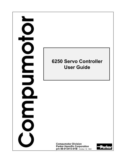
System Hardware Block Diagram<br />
Computer<br />
or<br />
Dumb Terminal<br />
RP240<br />
Front Panel<br />
Optional ±10V,<br />
14-bit Analog Input<br />
<strong>6250</strong><br />
RS-232C<br />
Interface<br />
Front Panel<br />
Interface<br />
<strong>6250</strong>-ANI<br />
Option<br />
<strong>6250</strong> Features<br />
Battery-backed<br />
RAM<br />
for<br />
user programs<br />
Motion<br />
Chip<br />
Axis #1<br />
Motion<br />
Chip<br />
Axis #2<br />
Operating System<br />
------------<br />
Microprocessor<br />
68000 - 12MHz<br />
Dual Port RAM<br />
DSP<br />
Drive Interface<br />
- ±10V Analog Output<br />
- Shutdown Output<br />
- Drive Fault Input<br />
- Inc. Encoder Interface<br />
- Position Latch<br />
- Output on Position<br />
Limits<br />
- CW & CCW End-of-travel<br />
- Home<br />
I/O<br />
- Enable Input<br />
- 2 Positon Latch Inputs<br />
- 24 Prog. Inputs<br />
- 24 Prog. Outputs<br />
- 2 Auxiliary Prog. Outputs<br />
Joystick Interface<br />
Limit<br />
Connections<br />
I/O<br />
Connections<br />
Joystick<br />
Up to 2 Axes of control<br />
Drive #1<br />
Drive #2<br />
Motor #1<br />
Motor #2<br />
Encoder<br />
#1<br />
Encoder<br />
#2<br />
❏ 1 to 2 axes of optically isolated —10V analog interface servo control<br />
❏ <strong>Servo</strong> feedback from incremental encoders. Analog feedback available with the<br />
<strong>6250</strong>-ANI option.<br />
❏ Controls servo drives in the velocity or torque mode<br />
❏ Fast digital signal processor (DSP) for sophisticated servo control (digital<br />
Proportional, Integral, and Velocity feedback, plus acceleration and velocity<br />
Feedforward—PIV&F)<br />
❏ S-curve motion profiling<br />
❏ Motion Architect ® is standard<br />
❏ Teach Mode<br />
❏ Windows-based visual data gathering and tuning aide available when using<br />
the Motion Architect ® <strong>Servo</strong> Tuner option<br />
❏ DOS Support Disk provided<br />
❏ 40,000 bytes of non-volatile memory for storing programs & paths<br />
❏ Capability to interrupt program execution on error conditions<br />
❏ 2-axis linear interpolation standard<br />
❏ Variable storage, conditional branching, and math capability<br />
❏ Program debug tools — single-step and trace modes, breakpoints, and<br />
simulation of I/O<br />
❏ Internal power supply<br />
❏ Direct interface to RP240 Front Panel<br />
❏ Operates stand-alone or interfaces to PCs & PLCs<br />
❏ 3-wire, RS-232C interface to PC or dumb terminal<br />
❏ 1.2 MHz pre-quadrature encoder feedback pulse frequency<br />
❏ I/O capabilities (all I/O are isolated):<br />
• ±10V analog control output (both axes )<br />
• Shutdown output (both axes)<br />
• Drive Fault input (both axes)<br />
• Incremental encoder input (both axes)<br />
• CW & CCW end-of-travel limit inputs (both axes)<br />
• Home limit input (both axes)<br />
DRIVE 1<br />
SHLD<br />
COM<br />
SHTNC<br />
SHTNO<br />
DFT<br />
AGND<br />
ANI<br />
CMD-<br />
CMD+<br />
DRIVE 2 ENCODER 2<br />
AUX<br />
SHLD<br />
COM<br />
SHTNC<br />
SHTNO<br />
DFT<br />
AGND<br />
ANI<br />
CMD-<br />
CMD+<br />
Rx<br />
Tx<br />
GND<br />
SHLD<br />
+5V<br />
OUT-P<br />
IN-P<br />
TRG-A<br />
TRG-B<br />
GND<br />
OUT-A<br />
OUT-B<br />
GND<br />
ENBL<br />
POWER<br />
EARTH N/A<br />
NEUT LINE<br />
<strong>6250</strong> Front Panel<br />
ENCODER 1<br />
• 3 8-bit analog inputs for joystick control and variable input<br />
• 2 (trigger) inputs — use for hardware position latch (±1 count accuracy)<br />
• 24 programmable inputs (Opto-22 compatible)<br />
• 24 programmable outputs (Opto-22 compatible)<br />
• 2 auxiliary programmable outputs that can be configured for accurate output on position within ±1 count<br />
❏ <strong>6250</strong>-ANI Option offers two ±10V, 14-bit analog inputs (one per axis) with anti-aliasing filter.<br />
RP240<br />
STATUS<br />
+5V<br />
A+<br />
A-<br />
B+<br />
B-<br />
Z+<br />
Z-<br />
GND<br />
SHLD<br />
+5V<br />
A+<br />
A-<br />
B+<br />
B-<br />
Z+<br />
Z-<br />
GND<br />
SHLD<br />
+5V<br />
GND<br />
Rx<br />
Tx<br />
SHLD<br />
J<br />
O<br />
Y<br />
S<br />
T<br />
I<br />
C<br />
K<br />
GRN : READY<br />
RED : RESET<br />
DRIVE1 OFF<br />
<strong>6250</strong><br />
DRIVE2 OFF<br />
2-AXIS SERVO<br />
CONTROLLER<br />
P<br />
R<br />
O<br />
G<br />
R<br />
A<br />
M<br />
M<br />
A<br />
B<br />
L<br />
E<br />
I<br />
N<br />
P<br />
U<br />
T<br />
S<br />
Compumotor<br />
LIM 1/2<br />
1CW<br />
1CCW<br />
1HOM<br />
GND<br />
2CW<br />
2CCW<br />
2HOM<br />
GND<br />
SHLD<br />
P<br />
R<br />
O<br />
G<br />
R<br />
A<br />
M<br />
M<br />
A<br />
B<br />
L<br />
E<br />
O<br />
U<br />
T<br />
P<br />
U<br />
T<br />
S<br />
2 <strong>6250</strong> <strong>Servo</strong> <strong>Controller</strong> <strong>User</strong> <strong>Guide</strong>
C H A P T E R ➁<br />
Getting Started<br />
Inspect The Shipment<br />
If you need to return<br />
any or all of the <strong>6250</strong><br />
system components,<br />
use the return<br />
procedures in Chapter<br />
9, Troubleshooting.<br />
The information in this chapter will enable you to:<br />
❏<br />
❏<br />
Verify that each component of your <strong>6250</strong> system has been delivered safely and configured<br />
properly<br />
Bench test the <strong>6250</strong>'s power and RS-232C interface to the host computer/terminal<br />
You should inspect your <strong>6250</strong> shipment upon receipt for obvious damage to its shipping<br />
container. Report any damage to the shipping company as soon as possible. Parker<br />
Compumotor cannot be held responsible for damage incurred in shipment. The items listed<br />
below should be present and in good condition.<br />
Part<br />
Part Number<br />
<strong>6250</strong> main unit (w/ship kit)<br />
<strong>6250</strong> (or <strong>6250</strong>-ANI, if so ordered *)<br />
Ship kit: <strong>6250</strong> <strong>Servo</strong> <strong>Controller</strong> <strong>User</strong> <strong>Guide</strong><br />
6000 Series Software Reference <strong>Guide</strong><br />
Motion Architect ® diskettes<br />
Motion Architect <strong>Servo</strong> Tuner diskette (optional)<br />
Motion Architect <strong>User</strong> <strong>Guide</strong><br />
DOS Support Disk<br />
DOS Support Disk Quick Reference<br />
8-foot AC power cord<br />
88-013413-01<br />
88-012966-01<br />
95-013070-01<br />
95-013070-02<br />
95-013714-01<br />
88-013056-01<br />
95-012266-01<br />
88-013258-01<br />
71-009039-01<br />
* The <strong>6250</strong>-ANI is an optional version of the <strong>6250</strong> which provides two ±10V, 14-bit analog inputs. If you ordered a<br />
-ANI option, check the serial tag on the side of the <strong>6250</strong>'s chassis; it should say <strong>6250</strong>-ANI.<br />
Pre-Wired Connections<br />
You should receive your <strong>6250</strong> with the following connections on the AUX connector prewired<br />
(from the factory):<br />
+5V supplies power to OUT-P and IN-P.<br />
This provides power to the output and input pull-ups.<br />
If this connection is broken, the <strong>6250</strong>'s<br />
analog command output signal is held<br />
to zero volts (independent of the DSP<br />
and microprocessor).<br />
AUX<br />
Rx<br />
Tx<br />
GND<br />
SHLD<br />
+5V<br />
OUT-P<br />
IN-P<br />
TRG-A<br />
TRG-B<br />
GND<br />
OUT-A<br />
OUT-B<br />
GND<br />
ENBL<br />
❏<br />
❏<br />
Output and input pull-ups<br />
(OUT-P and IN-P) connected<br />
to the +5V power supply (+5V)<br />
Enable input (ENBL)<br />
connected to ground (GND)<br />
➁ Getting Started 3
Bench Test<br />
This section leads you through step-by-step instructions to bench test your <strong>6250</strong> system.<br />
This is a temporary (bench top) configuration; the permanent installation will be performed in<br />
Chapter 3, Installation. In this section, you will complete the following tasks:<br />
➀<br />
➁<br />
➂<br />
➀ RS-232C Communications<br />
Computer-to-<br />
Terminal<br />
Conversion<br />
Set<br />
Communication<br />
Parameters<br />
Terminal<br />
Connections<br />
RS-232C Communications<br />
Connect Power Cable<br />
Test Procedure<br />
To communicate with the <strong>6250</strong>, your computer or terminal must have an RS-232C serial<br />
port.<br />
The <strong>6250</strong> uses a three-wire implementation of standard EIA RS-232C signals.<br />
If you are using an IBM/compatible computer, you must use a terminal emulator software<br />
package to communicate with the <strong>6250</strong>. The <strong>6250</strong> comes standard with Motion Architect ®<br />
for Windows and the 6000 DOS Support Disk; both provide a terminal emulator and<br />
program editor (refer to the Motion Architect <strong>User</strong> <strong>Guide</strong> or the 6000 DOS Support<br />
Disk Quick Reference for installation and other user information). You may also use<br />
communication programs such as Crosstalk, PC-Talk, and PROCOMM.<br />
Make sure your computer or terminal is set to the following communication parameters. You<br />
can configure these parameters by using one of the terminal emulation software packages listed<br />
above in Computer-to-Terminal Conversion. If you are using Motion Architect ® or the 6000<br />
DOS Support Disk, verify that the baud rate, data bit, parity, and stop bit parameters are set as<br />
follows:<br />
❏ Baud Rate: 9600*<br />
❏ Data Bits: 8<br />
❏ Parity: None<br />
❏ Stop Bits: 1<br />
❏ Full Duplex<br />
❏ XON/XOFF: Enabled<br />
* If your terminal is not capable of 9600 baud, use the <strong>6250</strong>'s auto-baud function to automatically<br />
set the <strong>6250</strong>'s baud rate equal to the terminal's baud rate. Refer to Optional DIP Switch Settings<br />
in Chapter 8 for instructions.<br />
The Receive Data (Rx), Transmit Data (Tx), and Ground (GND) signals are on the <strong>6250</strong>'s AUX<br />
connector (shown below). The ground (GND) connection on the connector is signal ground or<br />
common as opposed to earth ground (SHLD).<br />
NOTE<br />
If you intend to daisy chain multiple <strong>6250</strong> servo controllers, do not attempt the daisy-chain<br />
connections now. Daisy-chain instructions are provided in Chapter 5, Basic <strong>6250</strong> Features.<br />
Standard 9-Pin<br />
COM Port Pin Outs:<br />
Pin 3 = Transmit (Tx)<br />
Pin 2 = Receive (Rx)<br />
Pin 5 = Ground (GND)<br />
Standard 25-Pin<br />
COM Port Pin Outs:<br />
Pin 2 = Transmit (Tx)<br />
Pin 3 = Receive (Rx)<br />
Pin 7 = Ground (GND)<br />
Computer or<br />
Terminal<br />
(Serial Port)<br />
Tx<br />
Rx<br />
GND<br />
AUX<br />
Rx<br />
Tx<br />
GND<br />
SHLD<br />
+5V<br />
OUT-P<br />
IN-P<br />
TRG-A<br />
TRG-B<br />
GND<br />
OUT-A<br />
OUT-B<br />
GND<br />
ENBL<br />
4 <strong>6250</strong> <strong>Servo</strong> <strong>Controller</strong> <strong>User</strong> <strong>Guide</strong>
➁ Connect Power Cable<br />
The <strong>6250</strong> is shipped with an 8-foot power cable that is prewired and keyed. Attach the power<br />
cable to the <strong>6250</strong>'s POWER connector as illustrated below.<br />
WARNING<br />
DO NOT APPLY POWER<br />
TO THE <strong>6250</strong> UNTIL<br />
INSTRUCTED TO DO SO<br />
IN THE FOLLOWING<br />
TEST PROCEDURE.<br />
2-AXIS SERVO<br />
CONTROLLER<br />
85 - 240VAC<br />
If you have a power source other than<br />
85-240VAC, refer to Chapter 8 for<br />
specifications on alternative input power.<br />
Protective<br />
Rubber<br />
Boot<br />
POWER<br />
EARTH N/A<br />
NEUT LINE Compumotor<br />
➂ Test Procedure<br />
Use the following procedure to test the <strong>6250</strong>'s power and RS-232C connections. In Chapter 3,<br />
Installation, you will test the analog output, end-of-travel and home limits, encoders, RP240,<br />
joystick, and programmable I/O.<br />
➀<br />
Apply power to the <strong>6250</strong> by plugging the power cable into a grounded power source.<br />
CAUTION<br />
The earth ground connection must be made by plugging into a grounded receptacle<br />
or by physically connecting the green wire to earth ground.<br />
➁<br />
➂<br />
➃<br />
Watch the LEDs on the <strong>6250</strong>. The STATUS LED should be green, indicating the <strong>6250</strong> is ready<br />
for operation. The other two LEDs should be red because the drives are not yet enabled with the<br />
DRIVE11 command.<br />
If the STATUS LED is red, or if none of the LEDs illuminate, check your power source and cable<br />
connections. If these connections seem correct, disconnect power and consult Chapter 9,<br />
Troubleshooting.<br />
If you are using the 6000 DOS Support Disk, go to the Set-up menu and move the cursor down<br />
to CHECK OUT and press ENTER to automatically verify the communication interface to the<br />
<strong>6250</strong>.<br />
If the interface is not successful (Device not Ready message will flash on the screen), refer<br />
to the RS-232C troubleshooting procedures in Chapter 9, Troubleshooting.<br />
Initiate the terminal emulator in Motion Architect or in the 6000 DOS Support Disk (refer to<br />
the Motion Architect <strong>User</strong> <strong>Guide</strong> or the 6000 DOS Support Disk Quick<br />
Reference if necessary). You could also use your own terminal emulator package.<br />
Press the RETURN key. The cursor should move down one or two lines each time you press the<br />
RETURN key. If the cursor does not move as described, refer to the RS-232C troubleshooting<br />
procedures in Chapter 9, Troubleshooting.<br />
➁ Getting Started 5
C H A P T E R ➂<br />
Installation<br />
Installation Precautions<br />
Heat & Humidity<br />
Electrical Noise<br />
For more information<br />
on electrical noise,<br />
refer to Appendix A.<br />
The information in this chapter will enable you to:<br />
❏ Mount all system components properly<br />
❏ Connect all inputs and outputs properly<br />
❏ Verify that the complete system is installed properly<br />
To ensure proper installation, you should perform all the bench test procedures in Chapter 2,<br />
Getting Started, before proceeding with the permanent installation process in this chapter.<br />
To help ensure personal safety and long life of system components, pay special attention to<br />
the following installation precautions.<br />
WARNING<br />
Always remove power to the <strong>6250</strong> before performing wiring installation or changing DIP switch<br />
settings.<br />
Operate the <strong>6250</strong> system at an ambient temperature between 32° and 122°F (0° to 50°C). Keep<br />
the relative humidity below 95%.<br />
Minimize the potential for electrical noise before installing the <strong>6250</strong>, rather than attempting to<br />
solve such problems after installation. You can prevent electrical noise by observing the<br />
following installation precautions:<br />
❏<br />
❏<br />
❏<br />
Do not route high-voltage wires and low-level signals in the same conduit.<br />
Ensure that all components are properly grounded.<br />
Ensure that all wiring is properly shielded.<br />
➂ Installation 7
Airborne Contaminants<br />
Follow Installation Procedure<br />
➀ Mount the <strong>6250</strong><br />
Contaminants that may come in contact with the <strong>6250</strong> should be carefully controlled.<br />
Particulate contaminants, especially electrically conductive material such as metal shavings,<br />
can damage the <strong>6250</strong>.<br />
To ensure proper installation of the <strong>6250</strong> system, this chapter is organized in logical, linear<br />
steps. Deviating from this prescribed format may result in system problems.<br />
➀ Mount the <strong>6250</strong> <strong>Servo</strong> <strong>Controller</strong><br />
➁ Perform system connections<br />
➂ Perform the system test<br />
The <strong>6250</strong> should be installed in an enclosure that will protect it from atmospheric<br />
contaminants such as oil, metal, moisture, and dirt. Refer to the National Electrical<br />
Manufacturers Association (NEMA) specifications that pertain to your particular operating<br />
environment. The drawing below illustrates the <strong>6250</strong>'s dimensions.<br />
4.20 (106.68)<br />
9.61 (244.10)<br />
2.70 (68.58) 0.75 (19.05)<br />
10.00<br />
(254.00)<br />
10.80<br />
(274.32)<br />
11.60<br />
(294.64)<br />
inches (millimeters)<br />
0.80 (20.32)<br />
Provision for #10<br />
Mounting Screws<br />
(4 Plcs.)<br />
0.60 (15.25)<br />
Panel Layout<br />
➁<br />
System Connections<br />
If you mount the <strong>6250</strong> in an enclosure with other equipment, be sure to maintain at least 2<br />
inches of unrestricted air-flow space around the chassis. The maximum allowable ambient<br />
temperature directly below the <strong>6250</strong> is 122°F (50°C). Fan cooling may be necessary if<br />
adequate air flow is not provided.<br />
8 <strong>6250</strong> <strong>Servo</strong> <strong>Controller</strong> <strong>User</strong> <strong>Guide</strong>
Motor Driver Connections<br />
This section describes procedures for the following <strong>6250</strong> system connections:<br />
❏ Motor Drivers<br />
❏ End-of-travel and home limits<br />
❏ Encoders<br />
❏ Auxiliary +5VDC output<br />
❏ Output pull-up (OUT-P)<br />
❏ Programmable inputs and outputs (including auxiliary outputs OUT-A and OUT-B)<br />
❏ Trigger inputs (TRG-A and TRG-B)<br />
❏ RP240 Front Panel<br />
❏ Joystick and analog inputs<br />
❏ ANI analog inputs (<strong>6250</strong>-ANI option only)<br />
❏ Extending cables<br />
Refer to the bench test procedures in Chapter 2 for the following connections:<br />
❏ Power<br />
❏ RS-232C communications<br />
Refer to Chapter 5 for connection procedures on the following:<br />
❏ PLC<br />
❏ Thumbwheels<br />
❏ RS-232C daisy-chain<br />
NOTE<br />
Refer to Chapter 8, Hardware Reference, for system specifications and detailed I/O circuit<br />
drawings and signal descriptions.<br />
Before you connect the drives to the <strong>6250</strong>, configure your drives and connect the motors<br />
according to the user documentation for your drives.<br />
CAUTION<br />
Before connecting to your Motor/Drive system, be sure that power is not applied to the <strong>6250</strong>.<br />
The <strong>6250</strong> provides a standard ±10V analog control signal for use with any servo drive. The<br />
following table lists the <strong>6250</strong>'s motor driver connector pin outs; with this information you<br />
can connect the drives to the <strong>6250</strong>'s 9-pin screw terminal connectors as illustrated below. I/O<br />
circuit drawings are provided in Chapter 8, Hardware Reference.<br />
Pin # Name In/Out Description<br />
1 SHLD ----- Shield—internally connect to chassis (earth) ground.<br />
2 COM ----- Signal common for shutdown.<br />
3 SHTNC OUT Shutdown relay output to drives that require a closed contact to disable the drive.<br />
The shutdown relay is active (disabling the drive) when no power is applied to<br />
the <strong>6250</strong>. When the <strong>6250</strong> is powered up, the shutdown relay remains active until<br />
you issue the DRIVE11 command.<br />
Shutdown active (DRIVEØØ): this output is internally connected to COM.<br />
Shutdown inactive (DRIVE11): this output is disconnected from COM.<br />
4 SHTNO OUT Shutdown relay output to drives that require an open contact to disable the drive.<br />
The shutdown relay is active (disabling the drive) when no power is applied to<br />
the <strong>6250</strong>. When the <strong>6250</strong> is powered up, the shutdown relay remains active until<br />
you issue the DRIVE11 command.<br />
Shutdown active (DRIVEØØ): this output is disconnected from COM.<br />
Shutdown inactive (DRIVE11): this output is internally connected to COM.<br />
5 DFT IN Drive fault input. Set active level with the DRFLVL command.<br />
6 AGND ----- Analog ground.<br />
7 ANI IN ±10V, 14-Bit analog input (available only with the <strong>6250</strong>-ANI option).<br />
8 CMD- OUT Command signal return.<br />
9 CMD+ OUT Command output signal (±10V signal).<br />
➂ Installation 9
SAFETY FIRST <br />
If your drive does not have a shutdown input, install a manual emergency-stop switch for the drive's power supply.<br />
Connections to Compumotor and Digiplan <strong>Servo</strong> Drives<br />
APEX Series Drive<br />
A+ (pin 13)<br />
A– (pin 14)<br />
SRVON (pin 23)<br />
Voc (pin 24)<br />
B+ (pin 29)<br />
B– (pin 30)<br />
Z+ (pin 43)<br />
Z– (pin 44)<br />
VIN (pin 49)<br />
AGND (pin 50)<br />
↔<br />
↔<br />
↔<br />
↔<br />
↔<br />
↔<br />
↔<br />
↔<br />
↔<br />
↔<br />
<strong>6250</strong><br />
A–<br />
A+<br />
SHTNO<br />
+5V<br />
B+<br />
B–<br />
Z+<br />
Z–<br />
CMD+<br />
CMD–<br />
NOTE:<br />
Apex Series A+ connected to <strong>6250</strong>’s A–<br />
Apex Series A– connected to <strong>6250</strong>’s A+<br />
Reset<br />
Gnd<br />
Vel Int Enable<br />
Enable In<br />
Fault Out<br />
Gnd<br />
Command+<br />
Command–<br />
Tach Output<br />
Gnd<br />
+15V<br />
Gnd<br />
-15V<br />
APEX Series<br />
Drive<br />
CHA+<br />
CHA–<br />
CHB+<br />
CHB–<br />
CHZ+<br />
CHZ–<br />
Gnd<br />
DRIVE 1<br />
<strong>6250</strong><br />
SHLD<br />
COM<br />
SHTNC<br />
SHTNO<br />
DFT<br />
AGND<br />
ANI<br />
CMD-<br />
CMD+<br />
ENCODER 1<br />
+5V<br />
A+<br />
A–<br />
B+<br />
B–<br />
Z+<br />
Z–<br />
GND<br />
SHLD<br />
BL Drive<br />
V2 (pin 1)<br />
V1 (pin 2)<br />
GND (pin 4)<br />
RST (pin 5)<br />
+15V (pin 6)<br />
FT (pin 9)<br />
AOP (pin 10)<br />
AOP (pin 11)<br />
BOP (pin 12)<br />
BOP (pin 13)<br />
ZOP (pin 14)<br />
ZOP (pin 15)<br />
↔<br />
↔<br />
↔<br />
↔<br />
↔<br />
↔<br />
↔<br />
↔<br />
↔<br />
↔<br />
↔<br />
↔<br />
<strong>6250</strong><br />
CMD–<br />
CMD+<br />
GND<br />
COM<br />
SHTNO<br />
DFT<br />
A–<br />
A+<br />
B+<br />
B–<br />
Z+<br />
Z–<br />
BL Drive<br />
<strong>User</strong> I/O Connector<br />
15<br />
9<br />
NOTE: These connections will work only if<br />
BL jumper LK2 is set to position B<br />
(not the factory default position).<br />
8<br />
1<br />
DRIVE 1<br />
<strong>6250</strong><br />
SHLD<br />
COM<br />
SHTNC<br />
SHTNO<br />
DFT<br />
AGND<br />
ANI<br />
CMD–<br />
CMD+<br />
ENCODER 1<br />
+5V<br />
A+<br />
A–<br />
B+<br />
B–<br />
Z+<br />
Z–<br />
GND<br />
SHLD<br />
10 <strong>6250</strong> <strong>Servo</strong> <strong>Controller</strong> <strong>User</strong> <strong>Guide</strong>
Dynaserv Drive<br />
A+ (pin 13)<br />
A– (pin 14)<br />
SRVON (pin 23)<br />
Voc (pin 24)<br />
B+ (pin 29)<br />
B– (pin 30)<br />
Z+ (pin 43)<br />
Z– (pin 44)<br />
VIN (pin 49)<br />
AGND (pin 50)<br />
↔<br />
↔<br />
↔<br />
↔<br />
↔<br />
↔<br />
↔<br />
↔<br />
↔<br />
↔<br />
<strong>6250</strong><br />
A–<br />
A+<br />
SHTNO<br />
+5V<br />
B+<br />
B–<br />
Z+<br />
Z–<br />
CMD+<br />
CMD–<br />
Dynaserv Drive<br />
DN1<br />
(50-pin Honda Connector)<br />
1<br />
19<br />
33<br />
<strong>6250</strong><br />
DRIVE 1 ENCODER 1<br />
SHLD<br />
COM<br />
SHTNC<br />
SHTNO<br />
DFT<br />
AGND<br />
ANI<br />
CMD-<br />
CMD+<br />
+5V<br />
A+<br />
A-<br />
B+<br />
B-<br />
Z+<br />
Z-<br />
GND<br />
SHLD<br />
NOTE:<br />
Dynaserv A+ connected to <strong>6250</strong>’s A–<br />
Dynaserv A– connected to <strong>6250</strong>’s A+<br />
18<br />
50<br />
OEM670<br />
Drive<br />
<strong>6250</strong><br />
OEM670 Drive<br />
<strong>6250</strong><br />
1<br />
14<br />
CMD+ (pin 1)<br />
CMD– (pin 2)<br />
FAULT (pin 9)<br />
ENABLE (pin 10)<br />
GND (pin 11)<br />
GND (pin 16)<br />
↔<br />
↔<br />
↔<br />
↔<br />
↔<br />
↔<br />
CMD+<br />
CMD–<br />
DFT<br />
SHTNO<br />
COM<br />
AGND<br />
13<br />
25<br />
DRIVE 1<br />
SHLD<br />
COM<br />
SHTNC<br />
SHTNO<br />
DFT<br />
AGND<br />
ANI<br />
CMD–<br />
CMD+<br />
UD2 & UD5 Drives<br />
(UR3, UR4 or UR8 Rack)<br />
<strong>6250</strong><br />
UD2 & UD5 Drives<br />
+15V, LSW1 & LSW2<br />
VEL2<br />
VEL1<br />
0V<br />
FAULT<br />
EXT.DIS<br />
↔<br />
↔<br />
↔<br />
↔<br />
↔<br />
↔<br />
<strong>6250</strong><br />
SHTNO<br />
CMD–<br />
CMD+<br />
AGND<br />
DFT<br />
COM<br />
NOTE: These connections will<br />
work only if UD2/5 jumper LK1 is<br />
set to the 0V position (not the<br />
factory default position).<br />
18V AC<br />
0V<br />
18V AC<br />
+15V<br />
0V<br />
–15V<br />
0V<br />
RESET<br />
READY<br />
PSU FAULT<br />
PL9<br />
1<br />
G1<br />
G2<br />
VEL2<br />
VEL1<br />
SCREEN<br />
0V<br />
FAULT<br />
EXT.DIS<br />
LSW1<br />
LSW2<br />
PLB<br />
1<br />
DRIVE 1<br />
SHLD<br />
COM<br />
SHTNC<br />
SHTNO<br />
DFT<br />
AGND<br />
ANI<br />
CMD–<br />
CMD+<br />
If a drive fault occurs, you must cycle power to the drives, unless you control RESET<br />
(PL9 pin 8 on UR4 & UR8 racks, PL4 pin 8 on UR3 rack) with one of the <strong>6250</strong>’s<br />
general-purpose outputs. For additional instructions on detecting and reacting to UD<br />
rack faults, contact the Compumotor or Digiplan Applications Department.<br />
➂ Installation 11
UD12 Drive<br />
(UR4 Rack)<br />
<strong>6250</strong><br />
UD12 Drive<br />
+15V, LSW & LSW2<br />
VEL2<br />
VEL1<br />
0V<br />
FAULT<br />
EXT.DIS<br />
↔<br />
↔<br />
↔<br />
↔<br />
↔<br />
↔<br />
<strong>6250</strong><br />
SHTNO<br />
CMD–<br />
CMD+<br />
AGND<br />
DFT<br />
SHLD<br />
1<br />
18V AC<br />
0V<br />
18V AC<br />
+15V<br />
0V<br />
–15V<br />
0V<br />
RESET<br />
READY<br />
PSU FAULT<br />
1<br />
G1<br />
G2<br />
VEL2<br />
VEL1<br />
SCREEN<br />
0V<br />
FAULT<br />
EXT.DIS<br />
LSW1<br />
LSW2<br />
DRIVE 1<br />
SHLD<br />
COM<br />
SHTNC<br />
SHTNO<br />
DFT<br />
AGND<br />
ANI<br />
CMD–<br />
CMD+<br />
NOTE: These connections will<br />
work only if UD12 jumper LK3 is<br />
set to position A (not the factory<br />
default position).<br />
PL9A<br />
PLnC<br />
If a drive fault occurs, you must cycle power to the drives, unless you control RESET<br />
(pin 8 on the PL9 connector) with one of the <strong>6250</strong>'s general-purpose outputs.<br />
For additional instructions on detecting and reacting to UD rack faults, contact the<br />
Compumotor or Digiplan Applications Department.<br />
Z Drive<br />
ENABLE+<br />
ENABLE–<br />
GND<br />
GND<br />
CHA+<br />
CHA–<br />
CHB+<br />
CHB–<br />
CHZ+<br />
CHZ–<br />
ANALOG+<br />
ANALOG–<br />
Indexer Connector<br />
DRIVE FAULT (pin 9)<br />
↔<br />
↔<br />
↔<br />
↔<br />
↔<br />
↔<br />
↔<br />
↔<br />
↔<br />
↔<br />
↔<br />
↔<br />
↔<br />
<strong>6250</strong><br />
SHTNO<br />
COM<br />
AGND<br />
GND<br />
A–<br />
A+<br />
B+<br />
B–<br />
Z+<br />
Z–<br />
CMD+<br />
CMD–<br />
DFT<br />
NOTE:<br />
Z Drive CHA+ connected to <strong>6250</strong>’s A–<br />
Z Drive CHA– connected to <strong>6250</strong>’s A+<br />
ENABLE+<br />
ENABLE–<br />
RTI+<br />
RTI–<br />
RTO+<br />
RTO–<br />
GND<br />
Tx<br />
Rx<br />
GND<br />
CHA+<br />
CHA–<br />
CHB+<br />
CHB–<br />
CHZ+<br />
CHZ–<br />
ANALOG+<br />
ANALOG–<br />
INDEXER CONNECTOR<br />
Z Drive<br />
1<br />
I/O [1]<br />
14<br />
<strong>6250</strong><br />
DRIVE 1<br />
SHLD<br />
COM<br />
SHTNC<br />
SHTNO<br />
DFT<br />
AGND<br />
ANI<br />
CMD-<br />
CMD+<br />
ENCODER 1<br />
To <strong>6250</strong> Logic Gnd<br />
To <strong>6250</strong> Programmable Output<br />
+5V<br />
A+<br />
A–<br />
B+<br />
B–<br />
Z+<br />
Z–<br />
GND<br />
SHLD<br />
Pin #7 and #19 are FAULT RESET+ and FAULT<br />
RESET– respectively. These connections are required<br />
if you need to clear a drive fault via the <strong>6250</strong>. Activate<br />
the output for no longer than 140ms. If you choose not<br />
to make these connections, you will have to manually<br />
reset the Z Drive anytime a drive fault occurs.<br />
13<br />
25<br />
12 <strong>6250</strong> <strong>Servo</strong> <strong>Controller</strong> <strong>User</strong> <strong>Guide</strong>
End-of-Travel Limit Connections<br />
The <strong>6250</strong> provides CCW and CW end-of-travel limit inputs for both axes via the LIM 1/2<br />
connector. End-of-travel inputs serve as safety stops that prevent the load from crashing into<br />
mechanical stops and damaging equipment or injuring personnel. The drawing below<br />
illustrates typical end-of-travel limit switch connections.<br />
LIM 1/2<br />
1CW<br />
1CCW<br />
1HOM<br />
GND<br />
2CW<br />
2CCW<br />
2HOM<br />
GND<br />
SHLD<br />
End-of-Travel Limits<br />
Normally-closed switches*<br />
* LHLVL command changes<br />
active level of switches<br />
NOTE<br />
Motion will not occur until you do one of the following:<br />
❏ Install limit switches<br />
❏ Disable the limits with the LH command<br />
❏ Change the active level of the limits with the<br />
LHLVL command<br />
Use of hardware Mount normally-closed switches such that the load forces them to open before it reaches the<br />
(and software) endof-travel<br />
limits is physical travel limit (leave enough room for the load to stop). When the load opens<br />
discussed in detail in the limit switch, the motor comes to a halt. The actual stopping distance depends on motor<br />
the End-of-Travel<br />
Limits section in speed and the Hard Limit Deceleration (LHADA and/or LHAD) setting. The motor will not be<br />
Chapter 5. able to move in that same direction until you clear the limit (close the switch) and execute a<br />
move in the opposite direction (or you can disable the limits with the LH command, but this<br />
is recommended only if the motor is not coupled to the load). Use the TLIM or TAS<br />
commands to check the status of the limit switches.<br />
> RUNAWAY ><br />
If a runaway occurs (motor starts moving, usually at the fastest possible velocity, due to servo<br />
instability), the <strong>6250</strong> will shut down the drive if the maximum encoder position error (set with the<br />
SMPER command) is exceeded before an end-of-travel limit (either hardware of software) is<br />
encountered. However, if the maximum encoder position error is not exceeded by the time the<br />
limit is encountered, the <strong>6250</strong> may not be able to stop the motor.<br />
Home Limit Connections<br />
Use the Home input to establish a home position or zero position reference point. The home<br />
input (TTL compatible) is used for homing the motor. The encoder's Z channel pulse can be<br />
used in conjunction with the home switch to determine the home position. To use the<br />
encoder's Z channel, the HOMZ command must be enabled.<br />
Homing is discussed The <strong>6250</strong> is shipped configured for use with normally-open home switches. You can, if you<br />
in detail in the<br />
Homing section in wish, reverse the home input polarity (to use normally-closed switches) with the HOMLVL<br />
Chapter 5. command. The most common way to use the home switch is to mount it at a home reference<br />
position. The drawing below illustrates typical home limit switch connections to the <strong>6250</strong>.<br />
LIM 1/2<br />
1CW<br />
1CCW<br />
1HOM<br />
GND<br />
2CW<br />
2CCW<br />
2HOM<br />
GND<br />
SHLD<br />
Home Limit<br />
Normally-open switch*<br />
* HOMLVL command changes<br />
active level of switch<br />
CAUTION<br />
Compumotor cannot guarantee proper homing<br />
performance with the home and end-of-travel limit<br />
inputs tied together.<br />
➂ Installation 13
Encoder Connections<br />
The <strong>6250</strong> supports up to two incremental encoders. If you use encoders other than those<br />
supplied by Compumotor, pay special attention to the following requirements:<br />
❏<br />
❏<br />
Use incremental encoders with two-phase quadrature output. An index or Z channel output is<br />
optional. Differential outputs are recommended.<br />
It must be a 5V encoder to use the <strong>6250</strong>'s +5V output. Otherwise, it must be separately powered,<br />
with TTL-compatible or open-collector outputs.<br />
The illustration below shows the wiring techniques that you must use to connect encoders to<br />
the <strong>6250</strong>. Refer to Chapter 8 for the <strong>6250</strong>'s encoder input circuit drawing. If you are using the<br />
BL or Dynaserv drives, refer to the connection illustrations earlier in the Motor Driver<br />
Connections section.<br />
ENCODER 1 ENCODER 2<br />
+5V<br />
A+<br />
A-<br />
B+<br />
B-<br />
Z+<br />
Z-<br />
GND<br />
SHLD<br />
+5V<br />
A+<br />
A-<br />
B+<br />
B-<br />
Z+<br />
Z-<br />
GND<br />
SHLD<br />
+5VDC<br />
A Channel +<br />
A Channel -<br />
B Channel +<br />
B Channel -<br />
Z Channel +<br />
Z Channel -<br />
Ground<br />
Shield<br />
Incremental<br />
Encoder<br />
Note for Using Single-Ended Encoders<br />
If you are using a single-ended encoder leave the <strong>6250</strong>'s A-, B-, and Z- terminals not connected.<br />
Encoder<br />
Connector Pin<br />
Outs<br />
Each axis has a 9-pin Phoenix connector for incremental encoder connections. The pin-out<br />
description for the ENCODER connectors is provided below.<br />
Auxiliary +5V Output Connection<br />
Pin In/Out Name Compumotor E Series Description<br />
Encoder Cable Colors<br />
9 OUT +5V Red +5VDC output to power the encoder<br />
8 IN A Channel + Brown A+ channel quadrature signal from encoder<br />
7 IN A Channel - Brown/White A- channel quadrature signal from encoder<br />
6 IN B Channel + Green B+ channel quadrature signal from encoder<br />
5 IN B Channel - Green/White B- channel quadrature signal from encoder<br />
4 IN Z Channel + Orange Z+ channel quadrature signal from encoder<br />
3 IN Z Channel - Orange/White Z- channel quadrature signal from encoder<br />
2 ----- Ground Black Isolated logic ground<br />
1 ----- Shield Shield Internally connected to chassis ground (earth)<br />
The <strong>6250</strong> provides +5VDC output on the AUX, ENCODER, and RP240 connectors. As much as<br />
1.8A is available. 1.8A is sufficient power for the total load on all the I/O connectors. For<br />
example, using two encoders (each drawing 250mA) and one RP240 (drawing 100mA), 1.2A<br />
would be left for other purposes. The drawing below illustrates example connections for<br />
powering the output pull-up.<br />
Output and Input Pull-up Connections<br />
OUT-P (output pull-up) and IN-P (input<br />
pull-up), located on the AUX connector,<br />
provide power to the outputs and<br />
inputs. The <strong>6250</strong> is shipped from the<br />
factory with OUT-P and IN-P connected<br />
to +5V to power the outputs and inputs<br />
(see illustration at right).<br />
+5V supplies power to OUT-P and IN-P.<br />
This provides power to the output and input pull-ups.<br />
(As an alternative, you can connect OUT-P and IN-P<br />
to an external power source of up to 24V.)<br />
If this switch is opened, the <strong>6250</strong>'s analog<br />
command output signal is held to zero volts<br />
(independent of the DSP and microprocessor).<br />
Normally-closed<br />
switch<br />
AUX<br />
Rx<br />
Tx<br />
GND<br />
SHLD<br />
+5V<br />
OUT-P<br />
IN-P<br />
TRG-A<br />
TRG-B<br />
GND<br />
OUT-A<br />
OUT-B<br />
GND<br />
ENBL<br />
14 <strong>6250</strong> <strong>Servo</strong> <strong>Controller</strong> <strong>User</strong> <strong>Guide</strong>
Enable Input Connection<br />
The ENBL (enable) input is located on the AUX connector. The <strong>6250</strong> is shipped with ENBL<br />
wired to GND (see drawing) to allow motor motion.<br />
See the illustration above for an example connection using a normally-closed switch.<br />
Opening the switch sets the ±10V analog command output to zero volts and activates the<br />
shutdown outputs; this is done independent of microprocessor and DSP control. The encoder's<br />
position is retained when the ENBL input is activated. If the ENBL input is not grounded when<br />
motion is commanded, the error message WARNING: ENABLE INPUT INACTIVE will be<br />
displayed.<br />
If error bit #9 of the ERROR command is enabled, the error program (ERRORP) will be<br />
executed. You can check the status of the ENBL input with the TINO, INO, TER and ER<br />
commands.<br />
Programmable Inputs & Outputs Connections<br />
Change inputs from<br />
sourcing to sinking.<br />
Programmable<br />
I/O Pin Outs<br />
The PROGRAMMABLE INPUTS connector provides 24 programmable inputs and the<br />
PROGRAMMABLE OUTPUTS connector provides 24 programmable outputs. Two additional (and<br />
functionally identical) programmable outputs, OUT-A and OUT-B, are available on the AUX<br />
connector. Two additional trigger (position latch) inputs are also available on the AUX<br />
connector, but due to their functional differences they are discussed later in the Triggers<br />
section. All these inputs and outputs are optically isolated and TTL compatible.<br />
All 26 programmable outputs are pulled up using the OUT-P pin on the AUX connector (see<br />
illustration above). The <strong>6250</strong> is factory wired for +5VDC logic. If +5VDC is not to be used,<br />
disconnect OUT-P from the +5V terminal and connect OUT-P to an external supply of up to<br />
24V. Note: Even if you use an external 24V supply the switching thresholds remain TTL<br />
compatible ( ≤ 0.4V = Low,<br />
≥ 2.4 V = High).<br />
All 24 programmable inputs are pulled up to +5V by connecting the IN-P terminal to the +5V<br />
terminal on the AUX connector. If you wish to have the inputs sink current instead of source<br />
current, you can connect IN-P to GND. For compatibility with equipment operating at<br />
24VDC, the inputs may be pulled up to 24VDC by using an external power supply. The<br />
trigger inputs (TRG-A & TRG-B) are internally tied to 5V, but can have up to 24V connected to<br />
them.<br />
These I/O are typically used with normally-open or normally-closed switches; however, they<br />
can also be used with I/O module racks, PLCs, and thumbwheels (including the Compumotor<br />
TM8).<br />
If you are using PLCs or thumbwheels, refer to the connection instructions and application<br />
considerations provided in the Programmable Inputs and Outputs section of Chapter 5.<br />
Also provided in the Programmable Inputs and Outputs section are instructions for defining<br />
and controlling programmable inputs and outputs via programs written with the 6000 Series<br />
programming language.<br />
The following table lists the pin outs on the two 50-pin flat cable headers labeled<br />
PROGRAMMABLE INPUTS and PROGRAMMABLE OUTPUTS. Refer to Chapter 8, Hardware<br />
Reference, for internal I/O schematics.<br />
PROGRAMMABLE INPUTS Connector<br />
PROGRAMMABLE OUTPUTS Connector<br />
Pin # Function Pin # Function Pin # Function Pin # Function<br />
49 +5 VDC 23 Input #13 49 +5 VDC 23 Output #13<br />
47 Input #1 (LSB) 21 Input #14 47 Output #1 (LSB) 21 Output #14<br />
45 Input #2 19 Input #15 45 Output #2 19 Output #15<br />
43 Input #3 17 Input #16 43 Output #3 17 Output #16<br />
41 Input #4 15 Input #17 41 Output #4 15 Output #17<br />
39 Input #5 13 Input #18 39 Output #5 13 Output #18<br />
37 Input #6 11 Input #19 37 Output #6 11 Output #19<br />
35 Input #7 09 Input #20 35 Output #7 09 Output #20<br />
33 Input #8 07 Input #21 33 Output #8 07 Output #21<br />
31 Input #9 05 Input #22 31 Output #9 05 Output #22<br />
29 Input #10 03 Input #23 29 Output #10 03 Output #23<br />
➂ Installation 15
27 Input #11 01 Input #24 (MSB) 27 Output #11 01 Output #24 (MSB)<br />
25 Input #12 25 Output #12<br />
Optional VM50<br />
Adaptor<br />
NOTE: All even-numbered pins are connected to logic ground (DC ground).<br />
If you wish to use screw terminal connections for the 24 programmable I/O, Compumotor<br />
offers the VM50 adaptor (p/n VM50). If you wish to use screw terminal connections for both<br />
the 24 inputs and the 24 outputs, you will need two VM50 adaptors.<br />
The pin numbers on the VM50's screw terminals correspond to the same pin outs on the<br />
PROGRAMMABLE INPUTS and PROGRAMMABLE OUTPUTS connectors. The VM50 simply<br />
attaches to the <strong>6250</strong> via the 2-foot, 50-pin ribbon cable that comes with the VM50 (see<br />
drawing below).<br />
To order the VM50, contact your distributor or ATC, or call Compumotor at (800) 722-2282.<br />
<strong>6250</strong><br />
Programmable I/O<br />
Connectors<br />
2-Foot Cable<br />
(provided with VM50)<br />
VM50 snaps on to any<br />
standard DIN Rail<br />
2 4 6 8 10 12 14 16 18 20 22 24 26 28 30 32 34 36 38 40 42 44 46 48 50<br />
1 3 5 7 9 11 13 15 17 19 21 23 25 27 29 31 33 35 37 39 41 43 45 47 49<br />
VM50 Adaptor Board<br />
Trigger Input Connections<br />
The <strong>6250</strong> provides two trigger (position latch) inputs. Like the programmable inputs described<br />
earlier, trigger inputs can be connected to PLC outputs, discrete switches, or electronic sensors,<br />
and are monitored under program control. The status of triggers A and B is represented<br />
respectively by bits 25 and 26 in the [IN], INFNC, INLVL, ONIN, and TIN commands.<br />
Using the WAIT command, the <strong>6250</strong> can be programmed to wait until one or more inputs<br />
switch to a desired state before executing the next command.<br />
Normally-open switches *<br />
* The INLVL command changes the active level of inputs.<br />
AUX<br />
Rx<br />
Tx<br />
GND<br />
SHLD<br />
+5V<br />
OUT-P<br />
IN-P<br />
TRG-A<br />
TRG-B<br />
GND<br />
OUT-A<br />
OUT-B<br />
GND<br />
ENBL<br />
Position Latch<br />
Feature<br />
The trigger inputs function identically to the regular 24 programmable inputs, except when<br />
they are programmed with the Trigger Interrupt Function (INFNCi-H) command to function<br />
as position latch inputs.<br />
When configured as position latch inputs, the input enable/disable (INEN) command has no<br />
effect on the trigger inputs. Note: The position latch feature is discussed in the Programmable<br />
Inputs and Outputs section in Chapter 5)<br />
16 <strong>6250</strong> <strong>Servo</strong> <strong>Controller</strong> <strong>User</strong> <strong>Guide</strong>
RP240 Front Panel Connections (RP240 is optional)<br />
Using a four-wire shielded cable, connect the RP240 to the <strong>6250</strong>'s RP240 connector (see<br />
below). For cable lengths up to 50 feet, use 20 AWG wire (cable lengths longer than 50 feet<br />
are not recommended). Refer to the RP240 <strong>User</strong> <strong>Guide</strong> for mounting instructions.<br />
NOTE<br />
For the <strong>6250</strong> to recognize the RP240, the RP240 connection must be made prior to powering up<br />
(or resetting) the <strong>6250</strong>. If you connect the RP240 to the <strong>6250</strong> before powering up the <strong>6250</strong>, the<br />
<strong>6250</strong> will recognize the RP240 and send the *RP24Ø CONNECTED message to the RS-232C<br />
terminal. If the <strong>6250</strong> does not detect a RP240 upon power up or reset, then the following<br />
message will be sent to the RS-232C terminal: *NO REMOTE PANEL.<br />
Connector on back panel<br />
of RP240<br />
GND<br />
Rx<br />
Tx<br />
+5V<br />
Connector on<br />
RP240<br />
+5V<br />
GND<br />
Rx<br />
Tx<br />
SHLD<br />
Joystick and Analog Input Connections<br />
You can use the three analog inputs on the JOYSTICK connector for 2-axis joystick control of<br />
the axes, and/or as a low-resolution analog input (8-bit A/D, 1mV/bit) for process control.<br />
The Daedal JS6000 joystick is compatible with the Compumotor <strong>6250</strong>. To order the JS6000,<br />
contact Daedal at (800) 245-6903 or contact your local distributor.<br />
Refer to Chapter 5 The input range of the analog input is 0V to 2.5V. A joystick with a linear taper 5KΩ<br />
for a detailed<br />
discussion of joystick potentiometer (pot) with 60° of travel is recommended (the pot has 300° of travel, but<br />
control. typically only 60° is usable with a joystick). The pot should be adjusted so that its resistance<br />
is close to 0Ω when the joystick is all the way to one side, and about 1KΩ when the joystick<br />
is all the way to the other side. Also, connect a 1KΩ resistor between the analog input and<br />
+5V.<br />
Joystick<br />
Connector<br />
Pin Outs<br />
The JOYSTICK connector is a 25-pin D connector. The pin-out descriptions are provided in the<br />
table below. The <strong>6250</strong>'s internal analog input circuit diagram is provided in Chapter 8,<br />
Hardware Reference.<br />
Pin In/Out Name Description<br />
1 IN Analog Channel 1 8-bit analog input for joystick control of axis (can override with the ANVOEN and ANVO commands)<br />
2 IN Analog Channel 2 8-bit analog input for joystick control of axis (can override with the ANVOEN and ANVO commands)<br />
3 IN Analog Channel 3 8-bit analog input for joystick control of axis (can override with the ANVOEN and ANVO commands)<br />
4 — Unused ---------------<br />
8 — Shield Shield<br />
14 — Ground Ground<br />
15 IN Axes Select If only using one analog input, you can use this input to alternately control axes 1 or 2<br />
16 IN Velocity Select Input to select high or low velocity range (as defined with JOYVH or JOYVL command)<br />
17 IN Joystick Release Input to release the <strong>6250</strong> from joystick mode (JOY). Same as issuing the !JOYØØ command.<br />
Program execution will continue with the first statement after the joystick enable (JOY1) command.<br />
18 IN Joystick Trigger Status of this active-low input can be read by a program (using the INO or TINO commands) to<br />
control program flow, or to enter the <strong>6250</strong> into joystick mode.<br />
19 IN Joystick Auxiliary Status of this active-low input can be read by a program (using the INO or TINO commands) to<br />
control program flow, or to teach positions to a program.<br />
23 OUT +5VDC (out) +5VDC power output<br />
➂ Installation 17
Analog Inputs<br />
You can use the analog inputs for joystick control of the axes. An analog input can command<br />
an axis velocity from full CW to full CCW. The following drawing illustrates a typical<br />
joystick connection example.<br />
Joystick potentiometers are 5KΩ with<br />
60° of usable travel adjusted to span<br />
0Ω to 1KΩ.<br />
1KΩ Resistors *<br />
Joystick<br />
X Axis<br />
Y Axis<br />
* The 1KΩ resistors for velocity select,<br />
axes select, joystick trigger, & joystick<br />
auxiliary are for noise suppression only.<br />
5KΩ<br />
5KΩ<br />
23<br />
1<br />
J 2<br />
O<br />
YSTICK<br />
16<br />
15<br />
17<br />
18<br />
19<br />
14<br />
8<br />
SHLD<br />
+5VDC<br />
Analog Channel 1<br />
Analog Channel 2<br />
Velocity Select<br />
Axes Select<br />
Joystick Release<br />
Joystick Trigger<br />
Joystick Auxiliary<br />
GND<br />
N.C. Momentary<br />
Joystick Release<br />
Velocity Select<br />
Axes Select<br />
N.O. Momentary<br />
Joystick Trigger<br />
Joystick Aux.<br />
Axes Select Input<br />
Velocity Select<br />
Input<br />
Joystick Release<br />
Input<br />
Joystick Trigger<br />
Input<br />
Joystick Auxiliary<br />
Input<br />
You can define two configurations (JOYAXH and JOYAXL) that define which axes are<br />
controlled by which channels. The axes select input allows you to select the current<br />
configuration. An axes select input high references the JOYAXH command. An axes select<br />
input low references the JOYAXL command.<br />
One possible configuration is as follows: With axes select input high, analog channel #1<br />
controls axis one and analog channel #2 controls axis two (JOYAXH1,2). With axes select<br />
input low, analog channel #3 controls both axes (JOYAXL3,3).<br />
This input may be used to select either the high (high level-on input) or low (low level-on<br />
input) velocity range as defined with the JOYVH and JOYVL commands, respectively. The<br />
high range could be used to quickly move to a location while the low range could be used for<br />
accurate positioning. Refer to the illustration above. When this input is not connected, the<br />
low velocity range is selected.<br />
The joystick release input allows you to indicate to the <strong>6250</strong> that you have finished using the<br />
joystick and program execution may continue with the next statement. When a program<br />
enables joystick control of motion, program execution will stop and then resume when the<br />
user is finished with joystick mode (assuming the Continuous Command Execution Mode is<br />
disabled with the COMEXCØ command).<br />
The joystick release input has an internal pull-up resistor to +5V. When the joystick release<br />
input is not grounded, joystick enable statements (JOY1) will be disabled upon execution. To<br />
enable the joystick mode, the joystick release input must be inactive (connected to ground).<br />
Refer to the illustration above.<br />
The status of this input can be read by a program and may be used to control program flow<br />
(see INO and TINO command). Refer to the illustration above.<br />
The status of this input can be read by a program and may be used to control program flow<br />
(see INO and TINO command). Refer to the illustration above.<br />
ANI Analog Input Connections (<strong>6250</strong>-ANI Option Only)<br />
☞<br />
Application<br />
considerations are<br />
discussed in Chapter 5.<br />
The <strong>6250</strong>-ANI option offers two ±10V, 14-bit analog inputs<br />
(one ANI terminal found on each of the DRIVE connectors).<br />
These inputs are sampled at the servo sample rate (set with<br />
the SSFR command). The ANI input values are reported<br />
with the TANI and [ANI] commands.<br />
±10V Analog Input Source<br />
Ground<br />
Signal Source<br />
DRIVE 1<br />
SHLD<br />
COM<br />
SHTNC<br />
SHTNO<br />
DFT<br />
AGND<br />
ANI<br />
CMD-<br />
CMD+<br />
18 <strong>6250</strong> <strong>Servo</strong> <strong>Controller</strong> <strong>User</strong> <strong>Guide</strong>
Extending <strong>6250</strong> System Cables<br />
<strong>6250</strong>-to-Encoder<br />
Cables<br />
I/O Cables<br />
This section describes options for extending <strong>6250</strong> system drive, encoder, and I/O cables. If<br />
you wish to order longer cables, contact Compumotor's Customer Service Department at (800)<br />
722-2282 or contact your local Compumotor Distributor or ATC.<br />
Compumotor E Series encoders are supplied with a permanently attached 10-foot cable. The<br />
maximum cable length between Compumotor encoders and the <strong>6250</strong> is 100 feet. If you wish<br />
to lengthen the encoder cable yourself, use 24 AWG wire. Encoder cables should be shielded<br />
with the shield connected to SHLD (pin 1 on the ENCODER connector).<br />
You can also order encoders through Compumotor's Custom Products Group with the exact<br />
cable length you want.<br />
To avoid interference from external noise, you must shield all I/O cables, regardless of the<br />
length. The maximum length of cables is determined by the environment in which the<br />
equipment will be used. For cables longer than 50 feet or in electrically noisy environments,<br />
you should follow the guidelines below (refer also to illustration below).<br />
❏ 22 AWG wire is the minimum recommended wire size.<br />
❏ Use twisted pair shielded cables and connect the shield to the SHLD terminal on the <strong>6250</strong><br />
connector. Leave the other end of the shield disconnected.<br />
❏ Do not route these signals in the same conduit or wiring trays as high-voltage AC wiring.<br />
❏ Limit and trigger inputs are internally pulled up to +5VDC and are TTL compatible. In<br />
electrically noisy environments or when using long cable lengths, use an external pull-up<br />
resistor with a value of 330Ω to 2.2KΩ between the input and +5V. The external resistor will<br />
lower the input impedance and will make the input less susceptible to electrical noise.<br />
<strong>6250</strong><br />
5V<br />
Limit or Trigger<br />
GND<br />
Shield<br />
470Ω<br />
Input Switch<br />
Long Cable<br />
➂<br />
Installation Verification<br />
WARNING<br />
This installation verification section is intended to be executed with the drive not connected to<br />
the <strong>6250</strong>. Do not proceed until you are sure the drive is not connected.<br />
➀<br />
➁<br />
Return to the Test Procedure in Chapter 2 to test the drive/motor interface and the RS-232C<br />
interface.<br />
Use the information in the following table to test the features appropriate to your application.<br />
If you receive responses other than those expected, check your system wiring and refer to the<br />
command description in the 6000 Series Software Reference <strong>Guide</strong> for assistance.<br />
➂ Installation 19
NOTE<br />
The following table is based on the assumption that you have not changed the active levels of the<br />
<strong>6250</strong>'s inputs and outputs. Verify these settings with the following status commands:<br />
Command Entered<br />
INLVL<br />
HOMLVL<br />
LHLVL<br />
OUTLVL<br />
Response Should Be<br />
*INLVLØØØØ_ØØØØ_ØØØØ_ØØØØ_ØØØØ_ØØØØ_ØØ<br />
*HOMLVLØØ<br />
*LHLVLØØØØ<br />
*OUTLVLØØØØ_ØØØØ_ØØØØ_ØØØØ_ØØØØ_ØØØØ_ØØ<br />
Connections Test Procedure Response Format (left to right)<br />
End-of-travel<br />
and Home<br />
limits<br />
NOTE: If you are not using end-of-travel limits, issue the Disable Limits (LHØ,Ø) command<br />
and ignore the first two bits in each response field.<br />
Analog Output<br />
Signal<br />
Encoder<br />
Feedback<br />
Programmable<br />
Inputs<br />
(incl. triggers)<br />
Programmable<br />
Outputs<br />
➀ Close the end-of-travel switches and open the home switches.<br />
➁ Enter the TLIM command. The response should be *TLIM11Ø_11Ø.<br />
➂ Open the end-of-travel switches and close the home switches.<br />
➃ Enter the TLIM command. The response should be *TLIMØØ1_ØØ1.<br />
➄ Close the CW end-of-travel switch on axis 1 and open the home switch on axis 2.<br />
➅ Enter the TLIM command. The response should be *TLIM1Ø1_ØØØ.<br />
➀ If the drives are connected to the <strong>6250</strong>'s DRIVE connectors, disconnect them now.<br />
➁ Set all the gains to zero by entering the following: SGPØ,Ø, SGIØ,Ø, SGVØ,Ø,<br />
SGAFØ,Ø, SGVFØ,Ø<br />
➂ Enable the <strong>6250</strong> to send out the analog command by entering the DRIVE11 command.<br />
➃ Set the DAC output limit to 10 volts by entering the DACLIM1Ø,1Ø command.<br />
➄ Drive the analog output to the maximum positive range by entering the SOFFS1Ø,1Ø<br />
command.<br />
➅ Enter the TDAC command to check the analog output value. The response should be<br />
*TDAC+1Ø,1Ø.<br />
➆ Using a Digital Volt Meter (DVM), measure the actual analog output voltage between the<br />
CMD+ (analog command) and CMD- (analog command return) terminals. Compare the<br />
DVM reading to the entry for the SOFFS command (see step 5). With SOFFS1Ø, the DVM<br />
should read between +9.995V and +10.005V in a properly grounded and noise-free<br />
environment. If the reading deviates more than 0.1V from +10V, then there is either a<br />
problem with the system's grounding connection or the <strong>6250</strong>'s DAC is not functioning<br />
properly.<br />
➇ Repeat steps 5 through 7, using these servo output offset values:<br />
SOFFS-1Ø,-1Ø<br />
SOFFSØ,Ø<br />
SOFFS.ØØ5,.ØØ5<br />
SOFFS-.ØØ5-.ØØ5.<br />
➀ Enter the PSETØ,Ø command to set the commanded motor position on both axes to zero.<br />
➁ Enter the TPE command to determine the actual motor position. The response should be<br />
close to *TPE+Ø,+Ø (both motors at or about position zero).<br />
➂ Enter the TPC command to determine the commanded motor position. The response<br />
should be *TPC+Ø,+Ø (both motors at position zero).<br />
➃ Enter the TPER command to determine the position error between the commanded position<br />
(TPC) and the actual position (TPE). The response should be close to *TPER+Ø,+Ø.<br />
➄ Rotate encoders 1 rev: If the encoders are not coupled to the motors, manually rotate both<br />
encoders approximately one revolution in the clockwise direction. If the encoders are<br />
coupled to the motors, manually rotate both motors approximately one revolution.<br />
➅ Enter the TPE command to determine the actual motor position. The response should be<br />
close to *TPE+4ØØØ,+4ØØØ (That is the response if the encoder resolution is 4000<br />
counts/rev and you have not changed the default resolution settings—the <strong>6250</strong>'s default<br />
resolution is 4000, which is set with the ERES command. If your encoder's resolution is not<br />
4000 counts/rev, enter its resolution with the ERES command).<br />
➆ Enter the TPER command. The response should be close to *TPER-4ØØØ,-4ØØØ<br />
(4000-count position error), which is the difference between the commanded position (TPC)<br />
and the actual position (TPE).<br />
➀ Open the input switches or turn off the device driving the inputs.<br />
➁ Enter the TIN command.<br />
The response should be *TINØØØØ_ØØØØ_ØØØØ_ØØØØ_ØØØØ_ØØØØ_ØØ.<br />
➂ Close the input switches or turn on the device driving the inputs.<br />
➃ Enter the TIN command.<br />
The response should be *TIN1111_1111_1111_1111_1111_1111_11.<br />
➀ CAUTION: Disconnect all programmable outputs before proceeding to step ➁.<br />
➁ Enter the OUTALL1,26,1 command to turn on (sink current on) all outputs.<br />
➂ Enter the TOUT command.<br />
The response should be *TOUT1111_1111_1111_1111_1111_1111_11.<br />
➃ Enter the OUTALL1,26,Ø command to turn off all outputs.<br />
➄ Enter the TOUT command.<br />
The response should be *TOUTØØØØ_ØØØØ_ØØØØ_ØØØØ_ØØØØ_ØØØØ_ØØ.<br />
TLIM response:<br />
bit 1 = axis 1 CW limit<br />
bit 2 = axis 1 CCW limit<br />
bit 3 = axis 1 home limit<br />
bit 4 = axis 2 CW limit<br />
bit 5 = axis 2 CCW limit<br />
bit 6 = axis 2 home limit<br />
TDAC response (output voltage):<br />
±axis 1, ±axis 2<br />
TPER response (encoder counts):<br />
±encoder 1, ±encoder 2<br />
TPE response (motor counts):<br />
±encoder 1, ±encoder 2<br />
TPC response (commanded pos.):<br />
±axis 1, ±axis 2<br />
TIN response:<br />
bits 1-24 = prog. inputs 1 - 24<br />
bits 25 & 26 = TRG-A & TRG-B<br />
TOUT response:<br />
bits 1-24 = prog. outputs 1 - 24<br />
bits 25 & 26 = OUT-A & OUT-B<br />
20 <strong>6250</strong> <strong>Servo</strong> <strong>Controller</strong> <strong>User</strong> <strong>Guide</strong>
Installation Verification (cont.)<br />
RP240 ➀ Cycle power to the <strong>6250</strong>.<br />
➁ If the RP240 is connected properly, the RP240's status LED should be green and one of the<br />
messages on the computer or terminal display should read *RP24Ø CONNECTED.<br />
If the RP240's status LED is off, check to make sure the +5V connection is secure.<br />
If the RP240's status LED is green, but the message on the terminal reads *NO REMOTE<br />
PANEL, the RP240 Rx and Tx lines are probably switched. Remove power and correct.<br />
➂ Assuming you have not written a program to manipulate the RP240 display, the RP240<br />
screen should display the following:<br />
COMPUMOTOR <strong>6250</strong> SERVO CONTROLLER<br />
RUN JOG STATUS DRIVE DISPLAY ETC<br />
Joystick inputs<br />
➀ Open the joystick input switches or turn off the device driving the inputs.<br />
➁ Enter the TINO command.<br />
The response should be *TINOØØØØ_Ø1ØØ.<br />
➂ Close the input switches or turn on the device driving the inputs.<br />
➃ Enter the TINO command.<br />
The response should be *TINO1111_11ØØ.<br />
TINO response:<br />
bit 1 = joystick auxiliary<br />
bit 2 = joystick trigger<br />
bit 3 = joystick axes select<br />
bit 4 = joystick velocity select<br />
bit 5 = joystick release<br />
bit 6 = Enable input<br />
bits 7 & 8 are not used<br />
➃<br />
What's Next?<br />
At this point you should have successfully completed this chapter's mounting, connection, and<br />
test procedures for your <strong>6250</strong> system. If you intend to use thumbwheels or PLCs, or if you<br />
intend to daisy-chain multiple <strong>6250</strong>s, refer to the connection instructions and application<br />
considerations provided in Chapter 5.<br />
The following steps are recommended to prepare you for applying the <strong>6250</strong> in your<br />
application.<br />
Step ➀<br />
Step ➁<br />
Couple the Load<br />
Couple the motor to the load, and couple the encoder to the motor (or load, as appropriate).<br />
Perform the Basic System Configuration NOTE<br />
The set-up commands referred to in this step are not saved in the <strong>6250</strong>'s batterybacked<br />
RAM. Therefore, we suggest you add them to the startup (STARTP) program.<br />
For information in defining the startup program, refer to Automatic Program Execution on<br />
Power Up in Chapter 7, Programming Tips.<br />
Number of Axes:<br />
By configuring the number of axes in use, you limit the number of axes you can control.<br />
This may be desired if you are only using one of the two axes available. The INDAX<br />
command configures the number of axes. INDAX2 (the default setting) requires both<br />
command fields to be entered (e.g., A1,1). If you enter INDAX1, instead of entering<br />
A1,1 you should enter A1, and all responses from the <strong>6250</strong> will also only show the one<br />
field; if you enter the command A, the response will be *A1.<br />
Drive Fault Level:<br />
The drive fault level (DRFLVL) should be set to active high or active low for each axis<br />
(default is active low—DRFLVLØ). This output is active high (DRFLVL1) for the<br />
OEM670 and APEX series drives, and active low for the BL, UD2, UD5, and UD12<br />
drives. If you are using the Dynaserv or any other drive that does not have a drive fault<br />
output, set the drive fault level to active low (DRFLVLØ).<br />
NOTE<br />
Once the drive fault level has been configured, you must enable the drive fault input with<br />
the INFEN command before the input is usable.<br />
Encoder Resolution:<br />
The encoder resolution is determined by the resolution of the encoder used with the servo<br />
drive/motor system. The encoder resolution is essentially the number of steps, or counts<br />
(post quadrature), per unit of travel. For example, Compumotor E Series encoders are<br />
1,000-line encoders, and therefore have a 4,000 count/rev post-quadrature resolution.<br />
➂ Installation 21
If the encoder is mounted directly to the motor, then to ensure that the motor will move<br />
according to the programmed distance and velocity, the <strong>6250</strong>'s resolution must match the<br />
encoder's resolution. Use the ERES command to set the <strong>6250</strong>'s resolution (default setting<br />
is 4,000 counts/rev, selectable range is 200 to 1,024,000).<br />
NOTE<br />
The programming examples throughout this user guide assume an encoder resolution of<br />
4,000 counts post-quadrature (ERES4ØØØ,4ØØØ).<br />
Kill's Effect on the Drive:<br />
Normally, when you issue a Kill command (K, !K, or K) or activate a generalpurpose<br />
input configured as a kill input (see INFNCi-C command), motion is stopped at<br />
the hard limit (LHAD/LHADA) deceleration setting and the drive is left in the enabled state<br />
(DRIVE11).<br />
However, your application may require you to disable (shut down or de-energize) the drive in<br />
a Kill situation to, for example, prevent damage to the motor or other system mechanical<br />
components. If so, set the <strong>6250</strong> to the Disable Drive on Kill mode with the KDRIVE1<br />
command. In this mode, a kill command or kill input will shut down the drive<br />
immediately, letting the motor free wheel (without control from the drive) to a stop. When<br />
the drive is disabled (DRIVEØØ), the SHTNC relay output is connected to COM and the<br />
SHTNO relay output is disconnected from COM. To re-enable the drive, issue the DRIVE11<br />
command.<br />
Step ➂ Determine Your Application's Motion Control Requirements<br />
Applications can vary greatly from one to another. Consequently, the <strong>6250</strong> is equipped with<br />
many motion control features to satisfy a wide variety of application requirements—but not all<br />
features are appropriate for every application. Therefore, you must first determine the<br />
necessary motion features you need for your application. Once you have done that, you can<br />
proceed to Chapter 4 to tune the <strong>6250</strong>, and Chapters 5 through 7 to find out how to<br />
implement the <strong>6250</strong>'s motion control features in your application.<br />
Step ➃ Tune the <strong>Servo</strong> System (Chapter 4)<br />
Chapter 4 describes the <strong>6250</strong>'s tuning options and how to implement them.<br />
To effectively tune the <strong>6250</strong>, as well as the drives, we recommend using the interactive tuning<br />
features in the Motion Architect ® <strong>Servo</strong> Tuner option. It greatly improves your efficiency and<br />
gives you powerful graphical tools to measure the performance of the system. If you do not use<br />
Motion Architect, the only methods to monitor system performance are to use visual inspection<br />
(eyeballing it) or to use expensive lab equipment such as an oscilloscope.<br />
NOTE<br />
The <strong>Servo</strong> Tuner option is an add-on module and does not automatically come with the basic<br />
Motion Architect software package. To order your copy of the Motion Architect <strong>Servo</strong> Tuner,<br />
which is provided on a separate disk, contact your local Automation Technology Center.<br />
Step ➄ Implement the Necessary <strong>6250</strong> Features (Chapters 5 - 7)<br />
Chapters 5 through 7 describe how to implement the <strong>6250</strong>'s features in your application. You<br />
will develop your application by creating and refining motion programs using the 6000 Series<br />
Command Language. We recommend you use Motion Architect ® or the 6000 DOS Support<br />
Disk to aide in your programming efforts. Motion Architect and the 6000 DOS Support Disk<br />
are discussed briefly in Chapter 5, but for detailed user information refer to the Motion<br />
Architect <strong>User</strong> <strong>Guide</strong> or the 6000 DOS Support Disk Quick Reference.<br />
22 <strong>6250</strong> <strong>Servo</strong> <strong>Controller</strong> <strong>User</strong> <strong>Guide</strong>
C H A P T E R ➃<br />
<strong>Servo</strong> Tuning<br />
In a Hurry?<br />
<strong>Servo</strong> System Terminology<br />
<strong>Servo</strong> Tuning Terminology<br />
We strongly recommend tuning the <strong>6250</strong> before attempting to execute any motion functions.<br />
If you must execute motion quickly (e.g., for testing purposes), you should at least complete<br />
the Tuning Setup Procedure and Drive and <strong>Controller</strong> Tuning Procedures (see pages 29 - 38)<br />
until you have found a proportional feedback gain that can give a stable response for your<br />
system. Then you can proceed to execute your motion functions. Later on, you should read<br />
through this entire <strong>Servo</strong> Tuning chapter and follow its procedures to ensure your system is<br />
properly tuned.<br />
This section gives you with an overall understanding of the principles and the terminology<br />
used in tuning the Compumotor <strong>6250</strong> <strong>Servo</strong> <strong>Controller</strong>.<br />
The <strong>6250</strong> uses a digital control algorithm to control and maintain the position and velocity.<br />
The digital control algorithm consists of a set of numerical equations used to periodically<br />
(once every servo sampling period) calculate the value of the control signal output.<br />
The numerical terms of the equations consist of the current commanded and actual position<br />
values (plus a few from the past sampling period) and a set of control parameters. Each<br />
control parameter, commonly called a gain, has a specific function (see <strong>Servo</strong> Control<br />
Techniques later in this chapter). Tuning is the process of selecting and adjusting these gains<br />
to achieve optimal servo performance.<br />
When this control algorithm is used, the whole servo system is a closed loop system (see<br />
diagram below). It is called closed loop because the control algorithm accounts for both the<br />
command (position, velocity, tension, etc.) and the feedback data (from the encoder);<br />
therefore, it forms a closed loop of information flow.<br />
➃ <strong>Servo</strong> Tuning 21
When all gains are set to zero, the digital control algorithm is essentially disabled and the<br />
system becomes an open loop system (see diagram below). During system setup or<br />
troubleshooting, it is desirable to run the system in open loop so that you can independently<br />
test the drive and motor operation (refer to the Tuning Setup Procedure section of this chapter<br />
for instructions to run the <strong>6250</strong> in open loop).<br />
Closed Loop System<br />
Command<br />
Digital<br />
Control<br />
Algorithm<br />
Control<br />
Signal<br />
Offset<br />
Drive Command =<br />
Control Signal + Offset<br />
Motor<br />
Drive<br />
Motor<br />
Load<br />
Feedback Data<br />
Encoder<br />
Open Loop System<br />
Command<br />
Offset<br />
Drive Command = Offset<br />
Motor<br />
Drive<br />
Motor<br />
Load<br />
Encoder<br />
Position Variable Terminology<br />
The <strong>6250</strong> has the capability of providing a ±10V analog voltage output for commanding the<br />
motor's drive. After the digital control algorithm has calculated the digital control signal, this<br />
digital value is sent out from the DSP (digital signal processor) to the Digital-to-Analog<br />
converter (DAC). The DAC has an analog output range of -10V to +10V. It is often possible<br />
that the digital control signal calculated by the control algorithm can exceed this ±10V limit.<br />
When this happens, the analog output would just stay, or saturate, at the +10V or -10V limit<br />
until the motion variables (position, velocity, acceleration) change such that the control<br />
algorithm would calculate a control signal less than the limit. This phenomenon of reaching<br />
the output limit is called controller output saturation. When saturation occurs,<br />
increasing the gains does not help improve performance since the motor is already operating at<br />
its maximum level.<br />
Commanded<br />
Position<br />
In a servo system, there are two types of time-varying (value changes with time) position<br />
information used by the controller for control purposes: commanded position and actual<br />
position. You can use this information to determine if the system is positioning as you<br />
expect.<br />
The commanded position is calculated by the motion profile routine based on the<br />
acceleration (A, AA), deceleration (AD, ADA), velocity (V) and distance (D) command values and<br />
it is updated every servo sampling period. Therefore, the commanded position is the intended<br />
position at any given point of time. To view the commanded position, use the TPC (Transfer<br />
Commanded Position) command; the response represents the commanded position at the<br />
instant the command is received.<br />
When this user guide refers to the commanded position, it means this calculated time-varying<br />
commanded position, not the distance (D) command. Conversely, when this user guide refers to<br />
the position setpoint, it means the final intended distance specified with the distance (D)<br />
command. The following plot is a typical profile of the commanded position in preset (MCØ)<br />
mode.<br />
22 <strong>6250</strong> <strong>Servo</strong> <strong>Controller</strong> <strong>User</strong> <strong>Guide</strong>
Setpoint<br />
Position<br />
Commanded<br />
Position<br />
Profile<br />
Complete<br />
Distance<br />
( D )<br />
Acceleration<br />
Constant<br />
Velocity<br />
Deceleration<br />
Time<br />
Actual Position<br />
The other type of time-varying position information is the actual position; that is, the<br />
actual position of the motor/load measured with the encoder. Since this is the position<br />
achieved when the motor responds to the commanded position, we call the overall picture of<br />
the actual position over time the position response (see further discussion under <strong>Servo</strong><br />
Response Terminology).<br />
To view the actual position, use the TPE (Transfer Position of Encoder) command; the<br />
response represents the actual position at the instant the command is received. When the servo<br />
system is not properly tuned, the actual position is often not the same as the commanded<br />
position at any given point of time.<br />
The difference between the commanded position and actual position is the position error.<br />
To view the position error, use the TPER (Transfer Position Error) command; the response<br />
represents the position error at the instant the command is received. When the motor is not<br />
moving, the position error at that time is called the steady-state position error (see<br />
definition of steady-state under <strong>Servo</strong> Response Terminology). If a position error occurs when<br />
the motor is moving, it is called the position tracking error, or position following<br />
error.<br />
In some cases, even when the system is properly tuned, the position error can still be quite<br />
significant due to a combination of factors such as the desired profile, the motor limitation,<br />
the dynamic characteristics of the system, etc. For example, if the value of the velocity (V)<br />
command is higher than the maximum velocity the motor can physically achieve, then when<br />
the motor is commanded to travel at this velocity, the actual position will always lag behind<br />
the commanded position and a position error will accumulate, no matter how high the gains<br />
are.<br />
<strong>Servo</strong> Response Terminology<br />
Stability<br />
The first objective of tuning is to stabilize the system. The formal definition of system<br />
stability is that when a bounded input is introduced to the system, the output of the system<br />
is also bounded. What this means to a motion control system is that if the system is stable,<br />
then when the position setpoint is a finite value, the final actual position of the system is also<br />
a finite value.<br />
On the other hand, if the system is unstable, then no matter how small the position setpoint<br />
or how little a disturbance (motor torque variation, load change, encoder noise, etc.) the system<br />
receives, the position error will increase continuously, and exponentially in almost all cases.<br />
In practice, when the system experiences instability, the actual position will oscillate in an<br />
exponentially diverging fashion as shown in the drawing below. The definition here might<br />
contradict what some might perceive. One common perception shared by many is that<br />
whenever there is oscillation, the system is unstable. However, if the oscillation finally<br />
diminishes (damps out), even if it takes a long time, the system is still considered stable. The<br />
reason for this clarification is to avoid misinterpretation of what this user guide describes in<br />
the following sections.<br />
➃ <strong>Servo</strong> Tuning 23
Position<br />
Response Types<br />
The following table lists, describes, and illustrates the six basic types of position responses.<br />
The primary difference among these responses is due to damping, which is the suppression<br />
(or cancellation) of oscillation.<br />
Response Description Profile (position/time)<br />
Unstable<br />
Instability causes the position to<br />
oscillate in a exponentially diverging<br />
fashion.<br />
Position<br />
Time<br />
Over-damped<br />
Under-damped<br />
A highly damped, or over-damped,<br />
system gives a smooth but slower<br />
response.<br />
A slightly damped, or under-damped,<br />
system gives a slightly oscillatory<br />
response.<br />
Position Position<br />
Time<br />
Critically damped<br />
Oscillatory<br />
Chattering<br />
A critically-damped response is the<br />
most desirable because it optimizes<br />
the trade-off between damping and<br />
speed of response.<br />
An oscillatory response is<br />
characterized by a sustained position<br />
oscillation of equal amplitude.<br />
Chattering is a high-frequency, lowamplitude<br />
oscillation which is usually<br />
audible.<br />
Position Position Position<br />
Time<br />
Time<br />
Time<br />
Time<br />
Performance<br />
Measurements<br />
When we investigate the plot of the position response versus time, there are a few<br />
measurements that you can make to quantitatively assess the performance of the servo:<br />
❏ Overshoot—the measurement of the maximum magnitude that the actual position exceeds the<br />
position setpoint. It is usually measured in terms of the percentage of the setpoint value.<br />
❏ Rise Time—the time it takes the actual position to pass the setpoint.<br />
❏ Settling Time—the time between when the commanded position reaches the setpoint and the<br />
actual position settles within a certain percentage of the position setpoint. (Note the settling<br />
time definition here is different from that of a control engineering text book, but the goal of the<br />
performance measurement is still intact.)<br />
These three measurements are made before or shortly after the motor stops moving. When the<br />
motor is moving to reach and settle to the setpoint, we call such period of time the<br />
transient. When the motor is not moving, it is defined as in steady-state.<br />
A typical stable position response plot in preset mode (MCØ) is shown below.<br />
Target Zone Mode<br />
Settling Band<br />
Settling Time<br />
Setpoint<br />
Setpoint<br />
Position<br />
Commanded<br />
Position<br />
Actual<br />
Position<br />
Overshoot<br />
Steady State<br />
Position Error<br />
Rise Time<br />
Transient<br />
Time<br />
Steady State<br />
24 <strong>6250</strong> <strong>Servo</strong> <strong>Controller</strong> <strong>User</strong> <strong>Guide</strong>
6000 Series <strong>Servo</strong> Commands<br />
NOTE<br />
The following list contains a brief description of each servo-related 6000 Series command.<br />
More detailed information can be found in the rest of this chapter and within each<br />
command's description in the 6000 Series Software Reference <strong>Guide</strong>.<br />
Command Title Brief Description (detailed descriptions in 6000 Series Software Reference <strong>Guide</strong>)<br />
SGAF Acceleration Feedforward Gain Sets the acceleration feedforward gain in the PIV&F a servo algorithm.<br />
SGENB <strong>Servo</strong> Gain Set Enable Enables a previously-saved set of PIV&F gains. A set of gains is saved using the SGSET<br />
command.<br />
SGI Set Integral Feedback Gain Sets the integral gain in the PIV&F servo algorithm.<br />
SGILIM Set Integral Windup Limit Sets a limit on the correctional control signal that results from the integral gain action<br />
trying to compensate for a position error that persists too long.<br />
SGP Proportional Feedback Gain Sets the proportional gain in the PIV&F servo algorithm.<br />
SGSET Save a Set of <strong>Servo</strong> Gains Saves the presently-defined set of PIV&F gains as a particular gain set. Up to 5 gain sets<br />
can be saved and enabled at any point in a move profile, allowing different gains at different<br />
points in the profile.<br />
SGV Set Velocity Feedback Gain Sets the velocity gain in the PIV&F servo algorithm.<br />
SGVF Velocity Feedforward Gain Sets the velocity feedforward gain in the PIV&F v servo algorithm.<br />
SMPER Maximum Allowable Position Error Sets the maximum allowable error between the commanded position and the actual<br />
position as indicated by the encoder. If the error exceeds this limit, the <strong>6250</strong> shuts down<br />
the motor drive with the Shutdown output. You can enable the ERROR command to<br />
continually check for this error condition, and when it occurs to branch to a programmed<br />
response defined in the ERRORP program.<br />
SOFFS <strong>Servo</strong> Control Signal Offset Sets an offset to the commanded analog output voltage, which is sent to the drive system.<br />
SSFR <strong>Servo</strong> Frequency Ratio Sets the ratio between the update rate of the move trajectory and the update rate of the servo<br />
action. The intermediate position setpoints calculated by the trajectory generator is updated<br />
at a slower rate then the servo position correction. This command allows you to optimize<br />
this for your application. The default setting (SSF4) is sufficient for most applications.<br />
STRGTD<br />
STRGTE<br />
STRGTT<br />
STRGTV<br />
Target Zone Distance<br />
Target Zone Mode Enable<br />
Target Zone Timeout Period<br />
Target Zone Velocity<br />
When using the Target Zone Mode, enabled with the STRGTE command, the motor's<br />
actual position and actual velocity must be within the target zone (that is, within the<br />
distance zone defined by STRGTD and within the velocity zone defined by STRGTV). If the<br />
motor does not settle into the target zone before the timeout period set by STRGTT, the<br />
<strong>6250</strong> detects an error.<br />
To prevent subsequent commands/moves from being executed when this error condition<br />
occurs, you must enable the ERROR command to continually check for this error<br />
condition, and when it occurs to branch to a programmed response defined in the ERRORP<br />
program. Otherwise, subsequent commands/moves can be executed regardless of the<br />
motor's actual position and velocity.<br />
This feature is explained in greater detail later in the Target Zone section.<br />
TDAC Transfer DAC Voltage Transfers the voltage output from the <strong>6250</strong>'s digital-to-analog converter. This is the analog<br />
control signal output at the <strong>6250</strong>'s CMD terminal.<br />
TGAIN Transfer <strong>Servo</strong> Gains Transfers the currently active set of PIV&F gains. <strong>Servo</strong> gain sets are established with the<br />
SGSET command.<br />
TPC Transfer Position Commanded Transfers the commanded position (intermediate position setpoint) to the motor.<br />
TPE Transfer Position of Encoder Transfers the position of the encoder.<br />
TPER Transfer Position Error Transfers the error between the commanded position (TPC) and the actual position (TPE)<br />
as indicated by the encoder.<br />
TSGSET Transfer <strong>Servo</strong> Gain Set Transfers a previously-saved set of servo gain parameters. A gain set is saved with the<br />
SGSET command.<br />
TSTLT Transfer <strong>Servo</strong> Settling Time Transfers the time it took the last move to settle within the target zone (that is, within the<br />
distance zone defined by STRGTD and within the velocity zone defined by STRGTV). The<br />
Target Zone Mode does not need to be enabled to use this command.<br />
➃ <strong>Servo</strong> Tuning 25
<strong>Servo</strong> Control Techniques<br />
Velocity Feedforward<br />
(SGVF)<br />
Acceleration Feedforward<br />
(SGAF)<br />
To ensure that you are tuning your servo system properly, you should understand the tuning<br />
techniques described in this section.<br />
The <strong>6250</strong> employs a PIV&F servo control algorithm. The control techniques available in this<br />
system are as follows:<br />
P ..........Proportional Feedback (controlled with the SGP command)<br />
I ..........Integral Feedback (controlled with the SGI command)<br />
V .........Velocity Feedback (controlled with the SGV command)<br />
F ..........Velocity and Acceleration Feedforward (controlled by the SGVF and SGAF commands,<br />
respectively)<br />
The block diagram below shows these control techniques in relation to the servo control<br />
algorithm configuration. The following table presents a condensed summary of each control's<br />
effect on the servo system.<br />
<strong>Servo</strong> Control Algorithm<br />
<strong>Servo</strong> Drive System<br />
Current, Torque, or Velocity<br />
Control Signal<br />
Variable Integral Limit<br />
Drive<br />
(set with SGILIM)<br />
+ + Digital-to-Analog<br />
Integral Feedback<br />
Conversion (DAC)<br />
(SGI)<br />
+10V<br />
+ Analog<br />
Motor<br />
+ +<br />
- + -<br />
-10V<br />
Control Signal<br />
Load<br />
Proportional Feedback<br />
(SGP)<br />
Velocity Feedback<br />
(SGV)<br />
Encoder<br />
Gain Stability Damping Disturbance<br />
Rejection<br />
Steady<br />
State Error<br />
Tracking<br />
Error<br />
Proportional (SGP) Improve Improve Improve Improve Improve<br />
Integral (SGI) Degrade Degrade Improve Improve Improve<br />
Velocity Feedback (SGV) Improve Improve ------------- ------------- Degrade<br />
Velocity Feedforward (SGVF) ------------- ------------- ------------- ------------- Improve<br />
Acceleration Feedforward (SGAF) ------------- ------------- ------------- ------------- Improve<br />
Proportional Feedback Control (SGP)<br />
Proportional feedback is the most important feedback for stabilizing a servo system. When<br />
the <strong>6250</strong> uses proportional feedback, the control signal is linearly proportional to the encoder<br />
position error (the difference between the commanded position and the actual position—see<br />
TPER command). The proportional gain is set by the <strong>Servo</strong> Gain Proportional (SGP)<br />
command. Proportional feedback can be used to make the servo system more responsive, as<br />
well as reduce the steady state position error.<br />
Since the control is proportional to the position error, whenever there is any disturbance (such<br />
as torque ripple or a spring load) forcing the load away from its commanded position, the<br />
proportional control can immediately output a signal to move it back toward the commanded<br />
position. This function is called disturbance rejection.<br />
If you tune your system using only the proportional feedback, increasing the proportional<br />
feedback gain (SGP value) too much will cause the system response to be oscillatory,<br />
underdamped, or in some cases unstable.<br />
NOTE<br />
The proportional feedback gain (SGP) should never be set to zero, except when<br />
open-loop operation is required.<br />
26 <strong>6250</strong> <strong>Servo</strong> <strong>Controller</strong> <strong>User</strong> <strong>Guide</strong>
Integral Feedback Control (SGI)<br />
Controlling<br />
Integral Windup<br />
Using integral feedback control, the value of the control signal is integrated at a rate<br />
proportional to the encoder position error. The rate of integration is set by the <strong>Servo</strong> Gain<br />
Integral (SGI) command.<br />
The primary function of the integral control is to overcome friction and/or gravity and to reject<br />
disturbances so that steady state position error can be minimized or eliminated. This control<br />
action is important for achieving high system accuracy. However, if you can achieve<br />
acceptable position accuracy by using only the proportional feedback (SGP), then there is no<br />
need to use the integral feedback control.<br />
In the task of reducing position error, the integral gain (SGI) works differently than the<br />
proportional gain (SGP); this is because the magnitude of its control signal is not dependent<br />
on the magnitude of the position error as in the case of proportional feedback. If any position<br />
error persists, then the output of the integral term will ramp up over time until it is high<br />
enough to drive the error back to zero. Therefore, even a very small position error can be<br />
eliminated by the integral feedback control. By the same principle, integral feedback control<br />
can also reduce the tracking error when the system is commanded to cruise at constant<br />
velocity.<br />
If integral control (SGI) is used and an appreciable position error has persisted long enough<br />
during the transient period (time taken to reach the setpoint), the control signal generated by<br />
the integral action can end up too high and saturate to the maximum level of the controller's<br />
analog control signal output. This phenomenon is called integrator windup.<br />
After windup occurs, it will take a while before the integrator output returns to a level within<br />
the limit of the controller's output. Such a delay causes excessive position overshoot and<br />
oscillation. Therefore, the integral windup limit (SGILIM) command is provided for you to<br />
set the absolute limit of the integral and, in essence, turn off the integral action as soon as it<br />
reaches the limit; thus, position overshoot and oscillation can be reduced (see illustration<br />
below). The application of this feature is demonstrated in Step 4 of the Tuning Procedure<br />
below.<br />
Without SGILIM<br />
With SGILIM<br />
Position Overshoot<br />
Position Setpoint<br />
(D Command)<br />
Position Setpoint<br />
(D Command)<br />
Position<br />
Position Error at T 1<br />
Position<br />
Time<br />
Time<br />
Internal<br />
Integral<br />
Value<br />
Actual Output<br />
Generated<br />
by the Integral Term<br />
Integral at T 1<br />
T 1<br />
Max. Analog Output (+10V)<br />
Max. Analog Output (+10V)<br />
Windup<br />
Duration<br />
(wd)<br />
wd<br />
Integral<br />
Windup Limit<br />
(SGILIM)<br />
wd<br />
0V<br />
0V<br />
wd<br />
Min. Analog Output (-10V)<br />
Min. Analog Output (-10V)<br />
Velocity Feedback Control (SGV)<br />
➃ <strong>Servo</strong> Tuning 27
When velocity feedback control is used, the control signal is proportional to the encoder's<br />
velocity (rate of change of the actual position). The <strong>Servo</strong> Gain Velocity (SGV) command sets<br />
the gain, which is in turn multiplied by the encoder's velocity to produce the control signal.<br />
Since the velocity feedback acts upon the encoder's velocity, its control action essentially<br />
anticipates the position error and corrects it before it becomes too large. Such control tends to<br />
increase damping and improve the stability of the system.<br />
A high velocity feedback gain (SGV) can also increase the position tracking error when<br />
traveling at constant velocity. In addition, setting the velocity feedback gain too high tends to<br />
slow down (overdamp) the response to a commanded position change. If a high velocity<br />
feedback gain is needed for adequate damping, you can balance the tracking error by applying<br />
velocity feedforward control (increasing the SGVF value—discussed below).<br />
Since the encoder's velocity is derived by differentiating the encoder's position with a finite<br />
resolution, the finite word truncation effect and any fluctuation of the encoder's position would<br />
be highly magnified in the velocity value, and even more so when multiplied by a high<br />
velocity feedback gain. When the value of the velocity feedback gain has reached such a limit,<br />
the motor will chatter (high-frequency, low-amplitude oscillation) at steady state.<br />
Velocity Feedforward Control (SGVF)<br />
The purpose of velocity feedforward control is to improve tracking performance; that is, reduce<br />
the position error when the system is commanded to move at constant velocity. The tracking<br />
error is mainly attributed to three sources—friction, torque load, and velocity feedback control<br />
(SGV).<br />
Velocity feedforward control is directed by the <strong>Servo</strong> Gain Velocity Feedforward (SGVF)<br />
setting, which is in turn multiplied by the rate of change (velocity) of the commanded position<br />
to produce the control signal. Consequently, because the control signal is now proportional to<br />
the velocity of the commanded position, the <strong>6250</strong> essentially anticipates the commanded<br />
position and initiates a control signal ahead of time to more closely follow (track) the<br />
commanded position.<br />
Applications requiring linear interpolation can benefit from improved tracking performance;<br />
however, if your application only requires short, point-to-point moves, velocity feedforward<br />
control is not necessary.<br />
Because velocity feedforward control is not in the servo feedback loop (see <strong>Servo</strong> Control<br />
Algorithm drawing above), it does not affect the servo system's stability. Therefore, there is<br />
no limit on how high the velocity feedforward gain (SGVF) can be set, except when it<br />
saturates the control output (tries to exceed the <strong>6250</strong>'s ±10V analog control signal range).<br />
Acceleration Feedforward Control (SGAF)<br />
The purpose of acceleration feedforward control is to improve position tracking performance<br />
when the system is commanded to accelerate or decelerate.<br />
Acceleration feedforward control is directed by the <strong>Servo</strong> Gain Acceleration Feedforward<br />
(SGAF) setting, which is in turn multiplied by the acceleration of the commanded position to<br />
produce the control signal. Consequently, because the control signal is now proportional to<br />
the acceleration of the commanded position, the <strong>6250</strong> essentially anticipates the velocity of the<br />
commanded position and initiates a control signal ahead of time to more closely follow (track)<br />
the commanded position.<br />
28 <strong>6250</strong> <strong>Servo</strong> <strong>Controller</strong> <strong>User</strong> <strong>Guide</strong>
Tuning Setup Procedure<br />
Same as velocity feedforward control, this control action can improve the performance of linear<br />
interpolation applications. In addition, it also reduces the time required to reach the<br />
commanded velocity. However, if your application only requires short, point-to-point moves,<br />
acceleration feedforward control is not necessary.<br />
Acceleration feedforward control does not affect the servo system's stability, nor does it have<br />
any effect at constant velocity or at steady state.<br />
Use the following procedure to set up your servo system before completing the tuning<br />
procedures. You can perform this procedure for both axes simultaneously.<br />
Before you set up for tuning:<br />
Do not begin this procedure unless you are sure you have successfully completed the<br />
following system connection, test, and configuration procedures provided in Chapter 3:<br />
❏ Connect the motor drive (especially the shutdown output)<br />
❏ Connect and test the encoders<br />
❏ Connect and test the end-of-travel limits<br />
❏ Test the <strong>6250</strong>'s ±10V analog output<br />
❏ Couple the motor to the load, and couple the encoder to the motor (or load)<br />
❏ Configure the number of axes in use, drive fault level, and encoder resolution<br />
(these can also be configured in Motion Architect)<br />
EMERGENCY SHUTDOWN<br />
If you need to shutdown the motor drive during the tuning process (for instance, if the<br />
system becomes unstable or experiences a runaway), issue the DRIVEØØ command. If your<br />
motor drive does not have a shutdown input, use a manual emergency stop switch to<br />
shutdown the drive's power supply. You can also use the ENBL input to disable the <strong>6250</strong>'s<br />
analog output signal.<br />
Step 1<br />
Step 2<br />
Step 3<br />
Step 4<br />
Step 5<br />
Make sure the power to the motor drive is off.<br />
Apply power to the <strong>6250</strong> only and issue the DRIVE11 command. Measure the <strong>6250</strong>'s analog<br />
output between the CMD+ and CMD- terminals on the DRIVE connector with both an<br />
oscilloscope to check for noise and a digital volt-meter (DVM) to monitor the analog output.<br />
Both readings should be very close to zero volts. If an offset exists, ignore it for now; it will<br />
be taken care of later.<br />
NOTE<br />
Use an isolation (cheater) plug to isolate the<br />
oscilloscope from the power source ground; do<br />
the same to the DVM if it also uses the same<br />
power source. The isolation plug minimizes the<br />
system's noise level and eliminates ground loops.<br />
Isolation Plug<br />
Oscilloscope or DVM<br />
If your system has mechanical stops, manually move the load to a position mid-way between<br />
them.<br />
Enter these commands to zero all the gains and run the system in open loop:<br />
Command<br />
Desc r i p t i o n<br />
> SGPØ,Ø Set the proportional feedback gain to zero<br />
> SGVØ,Ø Set the velocity feedback gain to zero<br />
> SGIØ,Ø Set the integral feedback gain to zero<br />
> SGVFØ,Ø Set the velocity feedforward gain to zero<br />
> SGAFØ,Ø Set the acceleration feedforward gain to zero<br />
Apply power to the motor drive. The motor shaft should be stationary or perhaps turning very<br />
slowly (velocity drive). A small voltage to a torque drive, with little or no load attached, will<br />
cause it to accelerate to its maximum velocity. Since the torque demand at such a low voltage<br />
is very small, you can prevent the shaft from moving by holding it.<br />
➃ <strong>Servo</strong> Tuning 29
Step 6<br />
Step 7<br />
Observe the <strong>6250</strong>'s analog output noise level on the oscilloscope. The ideal noise level<br />
should be below 3.0mV (1/2-bit resolution of the <strong>6250</strong>'s digital-to-analog converter), but<br />
anything up to 10mV is acceptable in most cases.<br />
If the noise level is acceptable, proceed to Step 7. If the noise level is too high:<br />
a. Turn all the power off and tie the grounds of all the electrical components of your system<br />
to a single point, and connect this point to the ground of one of the drives.<br />
b. Shield the drive(s) properly and shield all the wiring that interconnect the components.<br />
c. After you have completed a and b above, turn on the controller only and start over from<br />
Step 2. If the noise level is still unacceptable, consult the noise suppression techniques<br />
described in Appendix A.<br />
The purpose of this step is to ensure that a positive voltage on the <strong>6250</strong>'s analog control<br />
signal output (from the CMD+ and CMD- terminals) results in the encoder counting in the<br />
positive direction.<br />
CAUTION<br />
This offset may cause a torque drive to accelerate the motor to a high speed, if little or no<br />
load (vs. rotor inertia) is attached.<br />
a. Using the SMPER command, set the maximum allowable position error to a step value<br />
equivalent to 1 rev. For instance, if the resolution value you entered for the ERES<br />
command was 4ØØØ (4,000 counts per rev), then you should enter the SMPER4ØØØ<br />
command.<br />
b. Enter the TPE command to check the current position of the encoder. Record this number<br />
for later use.<br />
c. Enter the SOFFSØ.2 command to introduce an offset servo analog output value of 0.2V<br />
to make the motor turn slowly in the positive (clockwise) direction. (The motor will<br />
stop when the maximum allowable position error is exceeded.) If the load has a large<br />
friction component, you may need to use a larger offset (SOFFS command) to affect<br />
motion.<br />
d. Use the TPE command again to observe the encoder position value. The value should<br />
have increased from the value observed in Step 7.b.<br />
If the encoder reading decreases when using a positive SOFFS setting, turn off the drive<br />
and the <strong>6250</strong> and swap the wires connected to the <strong>6250</strong>'s CMD+ and CMD- terminals,<br />
or the wires connected to the drive's analog control signal input and signal<br />
ground/common, whichever are more accessible. Then turn on the <strong>6250</strong> again, enter the<br />
DRIVE11 command, and repeat Steps 4 through 7.d. before proceeding to Step 8.<br />
e. Enter the SOFFSØ command to stop the motor, and enter the DRIVE11 command to reenable<br />
the drives.<br />
Step 8<br />
Step 9<br />
Step 10<br />
Having set the servo output offset to zero with the SOFFSØ command (see Step 7.e.), read the<br />
<strong>6250</strong>'s analog output with the DVM to determine if there is any offset caused by the electrical<br />
interconnections between the <strong>6250</strong> and the drive.<br />
If the DVM reads anything other than zero volts, enter the DVM's reading (but with the opposite<br />
polarity) as the offset adjustment with the SOFFS command. For example, if the DVM reading<br />
is 0.015V, then enter SOFFS-Ø.Ø15. If, after doing this, the reading is still not zero, then<br />
fine-tune it by trying SOFFS entries of slightly different values until the DVM reading is<br />
between ±3.0mV.<br />
If you have a velocity drive, the motor may still be turning due to the drive's balance/offset<br />
setting. If so, adjust the drive's balance/offset until the motor stops. Consult the drive's user<br />
documentation for instructions.<br />
Proceed to the Drive Tuning Procedure section to tune the velocity drive (if you are using a<br />
torque drive, skip to the <strong>Controller</strong> Tuning Procedure).<br />
30 <strong>6250</strong> <strong>Servo</strong> <strong>Controller</strong> <strong>User</strong> <strong>Guide</strong>
Drive Tuning Procedure (Velocity Drives Only)<br />
The Drive Tuning Procedure leads you through the following steps:<br />
➀ Launch and set up Motion Architect's Drive Tuner module.<br />
➁ Tune the drive to output the desired velocity at a given voltage from the <strong>6250</strong>.<br />
➂ Tune the drive (iteratively) to achieve the desired response.<br />
NOTE<br />
Be sure to complete the Tuning Setup Procedure before proceeding with the following drive<br />
tuning procedure. Unlike the Tuning Setup Procedure, you must tune one axis at a time.<br />
Step 1<br />
Launch and set up Motion Architect's Drive Tuner Module:<br />
To effectively tune the drive, you should use Motion Architect's interactive Drive Tuner<br />
module (this is available only if you have the <strong>Servo</strong> Tuner option for Motion<br />
Architect, part number 95-013714-01). It greatly improves your efficiency and gives<br />
you powerful graphical tools to measure the performance of the drive. The rest of this tuning<br />
procedure is based primarily on using the Drive Tuner module.<br />
a. Launch Motion Architect.<br />
b. Under the Product pull-down menu, choose Selection, select the <strong>6250</strong> and click<br />
Okay.<br />
c. Under the Utilities pull-down menu, choose Drive Tuner.<br />
d. Under the Communication pull-down menu, choose Connect to initiate the RS-232C<br />
link with the <strong>6250</strong> over the COM port. The drive shutdown and fault lights should be<br />
green; if not, press the Drive On button (if that does not work, check the shutdown<br />
output connection to the drive).<br />
e. Under the Setup pull-down menu, set the appropriate drive fault output level and the<br />
encoder resolution values.<br />
f. Click on the Step button in the Data Acquisition display. In the dialog box, select<br />
the voltage and duration for the step profile to be used in the iterative tuning process in<br />
Step 3 below.<br />
g. Click on the Sampling button in the Data Acquisition display. In the dialog box,<br />
select the data sampling period and frequency of samples for Motion Architect's data<br />
gathering function to be used in Step 3 below.<br />
Step 2 Tune the drive to output the desired velocity at a given voltage from the <strong>6250</strong>:<br />
a. If your system has mechanical stops, manually move the load to a position mid-way<br />
between them.<br />
b. Using your mouse or using the arrow keys, move the slide bar in the Drive Command<br />
Voltage display to select a voltage of 10.0 volts. Adjust the drive gain factor (sometimes<br />
called the tach gain) such that when the <strong>6250</strong>'s command output is 10V, the drive's velocity<br />
just reaches its maximum value. Refer to your drive's user documentation if necessary.<br />
EXAMPLE<br />
Suppose your drive can run at a max. velocity of 7000 rpm (or 116.67 rps). If the drive<br />
gain factor is 20 rps/V, then the drive will reach the maximum velocity (116.67 rps) when<br />
the <strong>6250</strong>'s command output is only 5.833V. This means the full range of ±10V is not fully<br />
usable. To use the full range of ±10V, the gain factor has to be adjusted to 11.667 rps/V.<br />
Drive manufactures usually provide a potentiometer for adjusting this gain factor. Some<br />
manufacturers provide a few preset values selectable with jumpers or DIP switches.<br />
c. Using your mouse or using the arrow keys, move the slide bar in the Drive Command<br />
Voltage display to select a voltage of 1.0 volts. The motor should start moving; note the<br />
value displayed in the Velocity data field. (If you are not using Motion Architect, enter<br />
the SOFFS1 command.)<br />
d. Click on the Step button. In the Drive Gain data field (1V = ___ units/sec), enter the<br />
value displayed in the Velocity data field from Step 2.b. above.<br />
e. After you have established the proper velocity-for-voltage setting, set the commanded<br />
voltage back to zero (see Step 2.b.).<br />
➃ <strong>Servo</strong> Tuning 31
Step 3<br />
Tune the drive (iteratively) to achieve the desired response:<br />
a. In the Data Acquisition display, select the Start button to trigger the short move and<br />
the data collection function.<br />
If you are not using Motion Architect:<br />
Enter the following commands to create and execute a step velocity command:<br />
Command<br />
Desc r i p t i o n<br />
> DEF STEPOUT Begin definition of the program called STEPOUT<br />
- SGPØ,Ø Set the SGP gain to zero<br />
- SGIØ,Ø Set the SGI gain to zero<br />
- SGVØ,Ø Set the SGV gain to zero<br />
- SGAFØ,Ø Set the SGAF gain to zero<br />
- SGVFØ,Ø Set the SGVF gain to zero<br />
- SMPERØ,Ø Disable checking the maximum allowable position error<br />
- SOFFSØ.5 Set the command output to 0.5 volts<br />
- T1 Wait for 1 second<br />
- SOFFSØ Set the command output to zero volts (stopping the motor)<br />
- SMPER4ØØØ,4ØØØ Re-enable checking the maximum allowable position error<br />
- END End definition of the program called STEPOUT<br />
> STEPOUT Execute the program called STEPOUT (the motor will move<br />
for 1 second and then stop)<br />
b. Observe the plot of the commanded velocity versus the actual velocity in the Captured<br />
Velocity graph (or on the oscilloscope).<br />
Using the tuning methods specified in the drive's user documentation, tune the drive to<br />
achieve a first-order response (no overshoot) as illustrated below—repeat Steps 3.a. and<br />
3.b. as necessary.<br />
Commanded Velocity<br />
Velocity<br />
Actual Velocity<br />
Time<br />
Step 4 Proceed to the <strong>Controller</strong> Tuning Procedure section to tune the <strong>6250</strong>.<br />
Motion Architect Automatic Gain Selection Feature<br />
The drive scale factor and step response information gathered in the latest Drive Tuner<br />
module session can be used in the <strong>Controller</strong> Tuner module to automatically select gains that<br />
should greatly shorten the iterative nature of the controller tuning process. Use of this<br />
feature is discussed in the <strong>Controller</strong> Tuning Procedure.<br />
<strong>Controller</strong> Tuning Procedure<br />
The <strong>Controller</strong> Tuning Procedure leads you through the following steps:<br />
➀ Launch Motion Architect's <strong>Controller</strong> Tuner module to tune the <strong>6250</strong>.<br />
➁ Select the <strong>6250</strong>'s servo Sampling Frequency Ratios (SSFR).<br />
➂ Set up Motion Architect's data gathering functions.<br />
➃ Optimize the Proportional (SGP) and Velocity (SGV) gains.<br />
An alternative would be to use Motion Architect's Automatic Gain Selection feature, which<br />
automatically calculates SGP and SGV gains (and SGI, if so desired) based on the last drive tuning<br />
session.<br />
➄ Use the Integral Feedback Gain (SGI) to reduce steady state error.<br />
➅ Use the Velocity Feedforward Gain (SGVF) to reduce position error at constant velocity.<br />
➆ Use the Acceleration Feedforward Gain (SGAF) to reduce position error during acceleration and<br />
deceleration.<br />
32 <strong>6250</strong> <strong>Servo</strong> <strong>Controller</strong> <strong>User</strong> <strong>Guide</strong>
Before you tune the <strong>6250</strong>:<br />
Be sure to complete the Tuning Setup Procedure (and the Drive Tuning Procedure, if you are<br />
using a velocity drive) before proceeding with the following tuning procedure. Unlike the<br />
Tuning Setup Procedure, you must tune one axis at a time; therefore, you will have to repeat<br />
Steps 3 through 7 below for the other axis.<br />
Step 1<br />
Launch Motion Architect's <strong>Controller</strong> Tuner Module:<br />
To effectively tune the <strong>6250</strong>, you should use Motion Architect's interactive tuning feature<br />
(this is available only if you have the <strong>Servo</strong> Tuner option for Motion<br />
Architect, part number 95-013714-01). It greatly improves your efficiency and gives<br />
you powerful graphical tools to measure the performance of the system. The rest of this<br />
tuning procedure is based primarily on using Motion Architect's <strong>Controller</strong> Tuner module.<br />
Use the following steps to engage the <strong>Controller</strong> Tuner module:<br />
a. Launch Motion Architect.<br />
b. Under the Product pull-down menu, choose Selection, select the <strong>6250</strong> and click<br />
Okay.<br />
c. Under the Utilities pull-down menu, choose <strong>Controller</strong> Tuner.<br />
d. Under the Communication pull-down menu, choose Connect to initiate the RS-232C<br />
link with the <strong>6250</strong> over the COM port.<br />
Tuning without Motion Architect ®<br />
If you do not use Motion Architect, use a computer (with a terminal emulator) or a dumb<br />
terminal to enter the commands noted in these procedures. Without Motion Architect, the<br />
only method of monitoring system performance is by visual inspection, or by using an analog<br />
type position transducer (potentiometer, LVDT, RVDT, etc.) to pick up the load's or motor's<br />
position displacement and monitoring the transducer output on a digital storage<br />
oscilloscope.<br />
Step 2<br />
Select the <strong>6250</strong>'s sampling frequency ratios (SSFR):<br />
The <strong>6250</strong>'s control signal is computed by the digital signal processor (DSP). The velocity of<br />
the commanded position, the velocity of the encoder position, and the integral of the position<br />
error are used for various control actions. These measurements are derived by the DSP from<br />
the position values sampled periodically at a fixed rate; this sampling rate is called the servo<br />
sampling frequency (samples/second).<br />
Higher sampling frequencies improve the accuracy of the velocity and integral values derived.<br />
A higher sampling frequency can also improve the tracking of a rapidly changing or oscillating<br />
position. Therefore, the servo sampling frequency is a key parameter that influences the servo<br />
system's stability and closed loop bandwidth.<br />
In addition to computing the <strong>6250</strong>'s control signal, the DSP also computes the commanded<br />
position trajectory. When the servo sampling frequency is increased, the motion trajectory<br />
update rate has to be decreased, and vice versa. The ratio between the servo sampling frequency<br />
and the trajectory update rate, called the sampling frequency ratio, depends on the requirements of<br />
your application and/or the dynamic characteristics of the system. The <strong>Servo</strong> Sampling<br />
Frequency Ratio (SSFR) command offers four selectable ratio settings. These four ratios and the<br />
actual sampling frequencies and sampling periods (reciprocal of sampling frequency) are shown<br />
below.<br />
NOTE<br />
Changing the active axes with the INDAX command will change the SSFR ratio.<br />
➃ <strong>Servo</strong> Tuning 33
# of Axes SSFR <strong>Servo</strong> Sampling Motion Trajectory Update<br />
Active<br />
(INDAX)<br />
Command<br />
Setting<br />
Frequency<br />
(samples/sec.)<br />
Period<br />
(µsec)<br />
Frequency<br />
(samples/sec.)<br />
Period<br />
(µsec)<br />
1 SSFR1 5555 180 5555 180<br />
1 SSFR2 6667 150 3333 300<br />
1 SSFR4 8000 125 2000 500<br />
1 SSFR8 10000 100 1250 800<br />
2 SSFR1 2667 375 2667 375<br />
2 SSFR2 3125 320 1563 640<br />
Default → 2 SSFR4 3636 275 909 1100<br />
2 SSFR8 4444 225 555 1800<br />
The general rule to determining the proper SSFR value is to first select the slowest servo<br />
sampling frequency that is able to give a satisfactory response. This can be done by experiment<br />
or based on the closed-loop bandwidth requirement for your application. (Keep in mind that<br />
increasing the SSFR value allows for higher bandwidths, but produces a rougher motion<br />
profile; conversely, decreasing the SSFR value provides a smoother profile, but makes the<br />
servo system less stable and slower to respond.)<br />
As an example, if your application requires a closed-loop bandwidth of 350 Hz, you can<br />
determine the minimum servo sampling frequency by using the rule of thumb—setting the<br />
servo sampling frequency at least 8 times higher than the bandwidth frequency—the required<br />
minimum servo sampling frequency would be 2800 Hz. If two axes are running, then you<br />
should try using the SSFR2 setting.<br />
The table below provides guidelines for various application requirements.<br />
Application Requirement SSFR1 SSFR2 SSFR4 SSFR8<br />
XY Linear Interpolation ✔ ✔<br />
Fast point-to-point motion ✔ ✔<br />
Regulation (speed, torque, etc.) ✔ ✔<br />
High natural frequency system<br />
✔<br />
Setting the Sampling Frequency Ratio<br />
Select a sampling ratio appropriate to your system now, before you proceed to tune each<br />
gain. In Motion Architect's <strong>Controller</strong> Tuner module select the System menu from the<br />
Setup pull-down menu and select the appropriate servo sampling (SSFR) value. (If you are<br />
not using Motion Architect, enter the appropriate SSFR command.)<br />
If you change the sampling frequency ratio (SSFR) after the tuning is complete and the new<br />
servo sampling frequency is lower than the previous one, the response may change and you<br />
may have to re-tune the system.<br />
Step 3<br />
Set up Motion Architect's data gathering functions:<br />
a. Click on the Motion button in the Data Acquisition display to show the Motion<br />
Profile Setup dialog box. Select the Step profile, set the Distance to 100 steps,<br />
select the Enable Motion box (✓ Enable Motion) for the axis you are tuning (make<br />
sure the other axis is deselected), and click ✓ OK.<br />
b. Click on the Capture button in the Data Acquisition display to show the Data<br />
Capture Setup dialog box. Select the axis you are currently tuning, select<br />
Commanded Position, Actual Position, and Analog <strong>Servo</strong> Output (deselect all<br />
other options), select Go Command as the trigger point that initiates data capture, and<br />
click ✓OK.<br />
c. Click on the Graph button in the Data Acquisition display to show the Graph Setup<br />
dialog box. In both graph axis dialog boxes, select the axis you are currently tuning.<br />
Select Graph 1 and use Commanded Position as the vertical axis and Time as the<br />
horizontal axis. Select Graph 2 and use Actual Position as the vertical axis and Time<br />
as the horizontal axis. (Make sure both Graph 1 and Graph 2 are enabled to be<br />
displayed.) Click ✓OK.<br />
34 <strong>6250</strong> <strong>Servo</strong> <strong>Controller</strong> <strong>User</strong> <strong>Guide</strong>
Step 4<br />
Optimize the Proportional (SGP) and Velocity (SGV) gains (see illustration for tuning process):<br />
➀<br />
➁<br />
If you are not using Motion Architect:<br />
Enter the following commands to create a step input profile (use a comma in the first data<br />
field when tuning axis 2—e.g., D,5Ø):<br />
Command Desc r i p t i o n<br />
> A999 Set acceleration to 999 revs/sec 2<br />
> AD999 Set deceleration to 999 revs/sec 2<br />
> V3Ø Set velocity to 30 revs/sec<br />
> D1ØØ Set distance to 100 steps<br />
Enter the SGPØ.5 command as a starting point for tuning (this is the Motion Architect's<br />
default SGP starting point).<br />
Motion Architect Automatic Gain Selection Option<br />
As an alternative to Steps 4.a. through 4.e. below, you may use Motion Architect's<br />
Automatic Gain Selection feature to automatically select SGP and SGV gains that should<br />
greatly shorten the iterative nature of the controller tuning process.<br />
To use this feature, select the Tune... menu item to display the Automatic Gain<br />
Selection dialog box. For each axis, provide the following information:<br />
➀ Under Control Law, select PV.<br />
➁ Under Drive Type, select either Velocity or Torque.<br />
➂ Enter the drive data:<br />
❏ For a velocity drive, fill in the Drive Scale Factor and Step Response data. If<br />
you select the Get Data button, these data fields will be filled in with the data<br />
captured from the last drive tuning session.<br />
❏ For a torque drive, fill in the Total Inertia and Motor/Drive Constants data.<br />
➃ Click the ✓OK button. Notice that the data fields in the Tuning Gains display show<br />
the new gain settings.<br />
☞<br />
Refer to the Tuning<br />
Scenario section<br />
later in this chapter<br />
for a case example.<br />
a. In the Data Acquisition display, select the Start button to trigger the step input<br />
move and gather data. (If you are not using Motion Architect, enter GO1 or GO,1<br />
depending on which axis is being tuned at the time.)<br />
b. Observe the plot of the commanded position versus the actual position in the Graph<br />
Display area (or on the oscilloscope). If the response is already very oscillatory, lower<br />
the gain (SGP); if it is sluggish (overdamped), increase the SGP gain. Repeat Steps 4.a.<br />
and 4.b. until the response is slightly under-damped.<br />
c. In the Tuning Gains panel, set the initial SGV value to 0.1 (or enter the SGVØ.1<br />
command if you are not using Motion Architect).<br />
d. As you did in Step 4.a., press the Start button (or enter GO1 or GO,1).<br />
e. Observe the plot in the Graph Display area (or on the oscilloscope). If the response is<br />
sluggish (overdamped), reduce the SGV gain. Repeat Steps 4.d. and 4.e. until the<br />
response is slightly under-damped.<br />
f. The flow diagram below shows you how to get the values of the proportional and velocity<br />
feedback gains for the fastest, well-damped response in a step-by-step fashion. The tuning<br />
principle here is based on these four characteristics:<br />
❏ Increasing the proportional gain (SGP) can speed up the response time and increase the<br />
damping.<br />
❏ Increasing the velocity feedback gain (SGV) can increase the damping more so than the<br />
proportional gain can, but also may slow down the response time.<br />
❏ When the SGP gain is too high, it can cause instability.<br />
❏ When the SGV gain is too high, it can cause the motor to chatter.<br />
➃ <strong>Servo</strong> Tuning 35
START<br />
Increase SGP<br />
UNTIL<br />
OR<br />
OR<br />
Decrease SGV<br />
UNTIL<br />
Increase SGV<br />
UNTIL<br />
OR<br />
Decrease SGV<br />
UNTIL<br />
OR<br />
STOP<br />
Decrease SGP<br />
UNTIL<br />
OR<br />
Increase SGV<br />
UNTIL<br />
OR<br />
Decrease SGV<br />
UNTIL<br />
36 <strong>6250</strong> <strong>Servo</strong> <strong>Controller</strong> <strong>User</strong> <strong>Guide</strong>
Step 5<br />
☞<br />
Steady state position<br />
error is described<br />
earlier in the<br />
Performance<br />
Measurements section.<br />
Use the Integral Feedback Gain (SGI) to reduce steady state error:<br />
a. Determine the steady state position error (the difference between the commanded position<br />
and the actual encoder position). You can determine this error value by using Motion<br />
Architect's Graph feature, or by issuing the TPER command when the motor is not<br />
moving, or by viewing the Motion Display (selected from the View pull-down menu).<br />
NOTE<br />
If the steady state position error is zero or so small that it is acceptable for your<br />
application, you do not need to use the integral gain.<br />
Step 6<br />
b. If you have to enter the integral feedback gain to reduce the steady error, start out with a<br />
small value (e.g., SGIØ.1). After the gain is entered, observe two things from the<br />
response:<br />
❏ Whether or not the magnitude of steady state error reduces<br />
❏ Whether or not the steady state error reduces to zero at a faster rate<br />
c. Keep increasing the gain to further improve these two measurements until the overshoot<br />
starts to increase and the response becomes oscillatory.<br />
d. There are three things you can do at this point (If these three things do not work, that<br />
means the integral gain is too high and you have to lower it.):<br />
1 st Lower the integral gain (SGI) value to reduce the overshoot.<br />
2 nd Check whether the <strong>6250</strong>'s analog output saturates the ±10V limit; you can do this by<br />
either using Motion Architect's data gathering feature (in the Graph Setup dialog<br />
box, select Analog <strong>Servo</strong> Output versus Time for Graph 1 and cancel the display<br />
for Graph 2), or by observing the signal from a digital oscilloscope. If it saturates,<br />
then lower the integral output limit by using the SGILIM command. This should<br />
help reduce the overshoot and shorten the settling time. Sometimes, even if the<br />
analog output is not saturated, you can still reduce the overshoot by lowering SGILIM<br />
to a value less than 10V. However, lowering it too much can impair the effectiveness<br />
of the integral feedback.<br />
3 rd You can still increase the velocity feedback gain (SGV value) further, provided that it<br />
is not already at the highest possible setting (causing the motor to chatter).<br />
Use the Velocity Feedforward Gain (SGVF) to reduce position error at constant speed:<br />
➀<br />
➁<br />
➂<br />
If you are not using Motion Architect:<br />
Execute a continuous (MC1 command) move, setting the acceleration, deceleration and<br />
velocity values appropriate to your application. Set the SGVF value to be the product of<br />
SGP ∗ SGV (if SGV = zero, set SGVF equal to SGP).<br />
Check the position error at constant velocity by issuing the TPER command.<br />
Increase SGVF to reduce the position error (repeat steps ➀ and ➁ as necessary).<br />
a. In the Graph Setup dialog box (via the Graph button), set Graph 1 to display<br />
commanded position versus time, and set Graph 2 to display actual encoder position<br />
versus time.<br />
Alternative setup if velocity error is critical to your application:<br />
Set up the Graph feature to compare commanded velocity versus time and actual<br />
velocity versus time, and set up the Capture feature to include commanded velocity.<br />
b. In the Motion Profile Setup dialog box (via the Motion button), select a trapezoidal<br />
or s-curve profile and set the acceleration, deceleration and velocity to the values<br />
appropriate to your application.<br />
c. In the Tuning Gains panel, set the initial value for SGVF as the product of SGP ∗<br />
SGV. For example, if SGP = 1.2 and SGV = 0.5, then<br />
SGVF = 1.2 ∗ 0.5 = 0.6. If SGV = zero, then just set SGVF = SGP.<br />
➃ <strong>Servo</strong> Tuning 37
d. In the Data Acquisition display, select the Start button to trigger the move and<br />
gather data.<br />
e. Note the plot in the Graph Display; the actual position (or velocity) probably lags the<br />
commanded position (or velocity).<br />
The objective is to increase SGVF until the lag is reduced to a level suitable for your<br />
application.<br />
Step 7<br />
Use the Acceleration Feedforward Gain (SGAF) to reduce position error during acceleration:<br />
➀<br />
➁<br />
➂<br />
If you are not using Motion Architect:<br />
Execute a continuous (MC1 command) move, setting the acceleration, deceleration and<br />
velocity values appropriate to your application. Set SGAF to 0.01 (SGAFØ.Ø1).<br />
Check the position error during acceleration by issuing the TPER command.<br />
Increase SGAF to reduce the position error (repeat steps ➀ and ➁ as necessary).<br />
a. In the Tuning Gains panel, set the initial value for SGAF to 0.01.<br />
b. In the Data Acquisition display, select the Start button.<br />
c. Note the plot in the Graph Display; the actual position (or velocity) probably lags the<br />
commanded position (or velocity).<br />
The objective is to increase SGAF until the lag is reduced to a level suitable for your<br />
application.<br />
Tuning Scenario<br />
The following tuning scenario presents an actual example of tuning Compumotor <strong>6250</strong> <strong>Servo</strong><br />
<strong>Controller</strong> with a Digiplan UD Drive system with a brushed motor and unknown load inertia.<br />
The UD Drive operates in velocity mode; therefore, the <strong>6250</strong>'s analog control signal output is a<br />
velocity command to the UD.<br />
This example shows how to obtain the highest possible proportional feedback (SGP) and<br />
velocity feedback (SGV) gains experimentally by using the flow diagram illustrated earlier in<br />
Step 5 of the Tuning Procedure.<br />
NOTE<br />
The steps shown below (steps 1 - 11) represent the major steps of the process; the actual<br />
progression between these steps usually requires several iterations.<br />
Step 1<br />
The motion command used for this example was a step command with a step size of 100. The<br />
plots shown are as they appeared in Motion Architect's <strong>Controller</strong> Tuner Module (X axis =<br />
time, Y axis = position).<br />
For a starting trial, we set the proportional<br />
feedback gain (SGP) to 2. As you can see by<br />
the plot, the response was slow.<br />
In the next step, we should increase SGP<br />
until the response is slightly underdamped.<br />
Commanded Position<br />
SGP = 2<br />
Actual Position<br />
38 <strong>6250</strong> <strong>Servo</strong> <strong>Controller</strong> <strong>User</strong> <strong>Guide</strong>
Step 2<br />
With SGP equal to 15, the response became<br />
slightly underdamped (see plot).<br />
Therefore, we should introduce the velocity<br />
feedback gain (SGV) to damp out the<br />
oscillation.<br />
SGP = 15<br />
Step 3<br />
With SGV equal to 2, the response turn out<br />
fairly well damped (see plot).<br />
At this point, the SGP should be raised again<br />
until oscillation or excessive overshoot<br />
appears.<br />
SGP = 15<br />
SGV = 2<br />
Step 4 As we iteratively increased SGP to 105,<br />
overshoot and chattering became significant<br />
(see plot). This meant either the SGV gain<br />
was too low and/or the SGP was too high.<br />
Next, we should try raising the SGV gain to<br />
see if it could damp out the overshoot and<br />
chattering.<br />
SGP = 105<br />
SGV = 2<br />
Step 5<br />
After the SGV gain was raised to 2.6, the<br />
overshoot was reduced but chattering was<br />
still quite pronounced. This meant either<br />
one or both of the gains was too high.<br />
The next step should be to lower the SGV<br />
gain first.<br />
SGP = 105<br />
SGV = 2.6<br />
Step 6<br />
Lowering the SGV gain to 2.3 did not help<br />
reduce the chattering by much.<br />
Therefore, we should lower the SGP gain<br />
until chattering stops.<br />
SGP = 105<br />
SGV = 2.3<br />
Step 7<br />
Chattering stopped after reducing the SGP<br />
gain to 85. However, the overshoot was<br />
still a little too high.<br />
The next step should be to try raising the<br />
SGV to damp out the overshoot.<br />
SGP = 85<br />
SGV = 2.3<br />
➃ <strong>Servo</strong> Tuning 39
Step 8<br />
After raising the SGV gain to 2.4, overshoot<br />
reduced a little, but chattering reappeared.<br />
This meant the gains were still too high.<br />
Next, we should lower the SGV gain until<br />
chattering stops.<br />
SGP = 85<br />
SGV = 2.4<br />
Step 9<br />
After lowering the SGV gain to 2.2 (even<br />
less than in Step 7—2.3), chattering<br />
stopped.<br />
Next we should lower the SGP gain.<br />
SGP = 85<br />
SGV = 2.2<br />
Step 10<br />
Overshoot was reduced very little after<br />
lowering the SGP gain to 70. (The SGV<br />
gain might have been lowered too much in<br />
Step 9.)<br />
Next, we should try raising the SGV gain<br />
again until the overshoot is gone.<br />
SGP = 70<br />
SGV = 2.2<br />
Step 11<br />
When we raised the SGV gain to 2.52, the<br />
step response became fast and very stable.<br />
SGP = 70<br />
SGV = 2.52<br />
Target Zone (Move Completion Criteria)<br />
Under default operation (Target Zone Mode not<br />
enabled), the <strong>6250</strong>'s move completion criteria is<br />
simply derived from the move trajectory. The<br />
<strong>6250</strong> considers the current preset move to be<br />
complete when the commanded trajectory has<br />
reached the desired target position; after that,<br />
subsequent commands/moves can be executed for<br />
that same axis. Consequently, the next move or<br />
external operation can begin before the actual<br />
position has settled to the commanded position<br />
(see diagram).<br />
Position<br />
Velocity<br />
Commanded<br />
Commanded<br />
Actual<br />
Actual<br />
Move is actually<br />
Completed<br />
Time<br />
When the Target Zone Mode<br />
is not enabled, the move is<br />
considered to be complete<br />
and subsequent moves can<br />
now be executed.<br />
Time<br />
40 <strong>6250</strong> <strong>Servo</strong> <strong>Controller</strong> <strong>User</strong> <strong>Guide</strong>
Target Zone Mode<br />
STRGTD<br />
(Distance Zone)<br />
Refer to Chapter 7<br />
for error program<br />
examples<br />
Damping is critical.<br />
To prevent premature command execution before the actual position settles into the<br />
commanded position, use the Target Zone Mode. In this mode, enabled with the STRGTE<br />
command, the move cannot be considered complete until the motor's actual position and actual<br />
velocity are within the target zone (that is, within the distance zone defined by STRGTD and<br />
less than or equal to the velocity defined by STRGTV). If the motor does not settle into the<br />
target zone before the timeout period set with the STRGTT command, the <strong>6250</strong> detects a<br />
timeout error (see illustration below).<br />
If the timeout error occurs, you can prevent subsequent command/move execution only if you<br />
enable the ERROR command to continually check for this error condition, and when it occurs<br />
to branch to a programmed response you can define in the ERRORP program.<br />
As an example, setting the distance zone to ±5 steps (STRGTD5), the velocity zone to ≤0.5 rps<br />
(STRGTVØ.5), and the timeout period to 1/2 second (STRGTT5ØØ), a move with a distance of<br />
8,000 steps (D8ØØØ) must end up between position 7,995 and 8,005 and settle down to ≤0.5<br />
rps within 500 ms (1/2 second) after the commanded profile is complete.<br />
To ensure that a move settles within the distance zone, it must be damped to the point that it<br />
will not move out of the zone in an oscillatory manner. This helps ensure the actual velocity<br />
falls within the target velocity zone set with the STRGTV command (see illustration below).<br />
Failed Move Completion<br />
STRGTD<br />
(Distance Zone)<br />
Successful Move Completion<br />
Position<br />
Commanded<br />
Move<br />
Completed<br />
Position<br />
Commanded<br />
Move<br />
Completed<br />
Actual<br />
Actual<br />
Time<br />
Time<br />
Velocity<br />
Actual<br />
STRGTT<br />
(Timeout Period)<br />
Timeout Occurs,<br />
Error Bit Set<br />
Velocity<br />
Commanded<br />
Actual<br />
STRGTT<br />
(Timeout Period)<br />
STRGTV<br />
(Velocity Zone)<br />
Commanded<br />
STRGTV<br />
(Velocity Zone)<br />
Time<br />
Time<br />
TSTLT<br />
(Actual Settling Time)<br />
Checking the<br />
Actual Settling<br />
Time<br />
Using the TSTLT command, you can display the actual time it took the last move to settle<br />
into the target zone (that is, within the distance zone defined by STRGTD and less than or<br />
equal to the velocity defined by STRGTV). The reported value represents milliseconds. This<br />
command is usable whether or not the Target Zone Settling Mode is enabled with the<br />
STRGTE command.<br />
➃ <strong>Servo</strong> Tuning 41
C H A P T E R ➄<br />
Basic <strong>6250</strong> Features<br />
The information in this chapter will enable you to understand and implement the <strong>6250</strong>'s basic<br />
features into your application:<br />
❏<br />
❏<br />
❏<br />
❏<br />
❏<br />
❏<br />
❏<br />
❏<br />
❏<br />
Support Software:<br />
• Motion Architect<br />
• 6000 DOS Support Disk<br />
Safety Features<br />
Scaling<br />
End-of-Travel Limits<br />
Homing<br />
Positioning Modes<br />
<strong>User</strong> Interface Options:<br />
• Programmable I/O<br />
• Thumbwheel Interface<br />
• PLC Interface<br />
• Joystick Interface<br />
• 14-Bit Analog Input Interface (<strong>6250</strong>-ANI Option only)<br />
• RP240 Front Panel Interface<br />
• Host Compumotor Control<br />
Variables<br />
RS-232C Daisy-chaining<br />
Before You Proceed With This Chapter<br />
CAUTION<br />
To ensure proper installation and operator safety, you should complete all the installation and<br />
test procedures provided in Chapter 2 and Chapter 3, and complete the tuning procedures in<br />
Chapter 4, before proceeding with any of the motion programming procedures in this chapter.<br />
6000 Series Software Reference <strong>Guide</strong><br />
Since this chapter often refers to the 6000 Series Command Language employed by the <strong>6250</strong>'s<br />
operating system, keep the 6000 Series Software Reference <strong>Guide</strong> nearby as a<br />
reference.<br />
➄ Basic <strong>6250</strong> Features 43
Compumotor Bulletin Board Service<br />
Basic Motion Control Concepts<br />
Support Software<br />
6000 DOS Support Disk<br />
Motion Architect®<br />
Compumotor offers an electronic bulletin board service (BBS)—free of charge. The BBS<br />
allows you to send or receive messages and download the latest revisions of Compumotor<br />
software (such as support software, sample programs, and programming tools).<br />
To dial in, you must have at least a 2400 baud modem with your computer. Set the baud rate<br />
to 2400, 8 data bits, 1 stop bit, and NO parity; any communications program such as<br />
Procomm, Crosstalk, or PC-Talk should allow you to set these. The BBS number is<br />
707-584-4059.<br />
Once connected, you will be asked some questions about yourself. Take your time in<br />
answering them, because you will only have to do this once. When you have completed the<br />
personal information, you are free to explore the services of the bulletin board.<br />
If you are unfamiliar with motion control concepts such as motion profiles, mechanical<br />
factors, positional accuracy, and repeatability refer to the Engineering Reference section of the<br />
Parker Compumotor/Digiplan Positioning Control Systems and Drives Catalog.<br />
The <strong>6250</strong> is shipped with two support software tools, Motion Architect ® and the 6000 DOS<br />
Support Disk.<br />
The 6000 DOS Support Disk (p/n 95-012266-01) contains a program that provides terminal<br />
emulation and program editing capabilities specifically designed for use with any 6000 Series<br />
stand-alone product. Also included on the disk are sample 6000 command language programs.<br />
For more detailed user information, refer to the 6000 DOS Support Disk Quick<br />
Reference.<br />
Motion Architect ® is an intuitive Microsoft ® Windows based programming tool. A brief<br />
description of Motion Architect's basic features is provided below. For more detailed user<br />
information, refer to the Motion Architect ® <strong>User</strong> <strong>Guide</strong>.<br />
❏<br />
❏<br />
❏<br />
❏<br />
❏<br />
❏<br />
System Configurator and Code Generator: Automatically generate controller code of<br />
basic system set-up parameters (I/O definitions, encoder operations, etc.).<br />
Tuning and Data Gathering Tool (<strong>Servo</strong> Tuner option for Motion Architect):<br />
Tune the attached drives and the <strong>6250</strong> and receive instant data feedback on customizable<br />
displays. The <strong>Servo</strong> Tuner option is an add-on module and does not automatically come with the<br />
basic Motion Architect software package. To order your copy of Motion Architect <strong>Servo</strong> Tuner,<br />
contact your local Automation Technology Center.<br />
Program Editor: Create blocks or lines of <strong>6250</strong> controller code, or copy portions of code<br />
from previous files. You can save program editor files for later use in BASIC, C, etc., or in the<br />
terminal emulator or test panel.<br />
Terminal Emulator: Communicating directly with the <strong>6250</strong>, the terminal emulator allows<br />
you to type in and execute controller code and transfer code files to and from the <strong>6250</strong>.<br />
Operator Panel and Program Tester: You can create your own test panel to run your<br />
programs and check the activity of I/O, motion, system status, etc. This can be invaluable during<br />
start-ups and when fine tuning machine performance.<br />
On-line Context-sensitive Help and Command Reference: These on-line<br />
resources provide help information about Motion Architect, as well as interactive access to the<br />
contents of the 6000 Series Software Reference <strong>Guide</strong>.<br />
44 <strong>6250</strong> <strong>Servo</strong> <strong>Controller</strong> <strong>User</strong> <strong>Guide</strong>
<strong>6250</strong> Safety Features<br />
To help ensure a safe operating environment, you should take advantage of the <strong>6250</strong>'s safety<br />
features (see table). See Also refers you to the section in this user guide where you can find<br />
more in-depth information about the feature (system connections and/or programming<br />
instructions).<br />
Feature Description See Also<br />
Enable Input<br />
Shutdown<br />
Outputs<br />
Drive Fault<br />
Inputs<br />
End-of-travel<br />
Limit Inputs<br />
<strong>User</strong> Fault<br />
Input<br />
Maximum<br />
Allowable<br />
Position Error<br />
The enable input (ENBL), found on pin #14 on the AUX<br />
connector, is provided as an emergency stop input to the<br />
<strong>6250</strong>.<br />
When you open the ENBL input, with respect to GND, the<br />
analog output voltage between CMD+ and CMD- is clamped<br />
to almost zero, and the shutdown outputs are activated on<br />
both axes. Clamping occurs independent of the<br />
microprocessor and the DSP. (The clamping circuit is also<br />
connected to the watchdog timer; if the <strong>6250</strong>'s<br />
microprocessor fails, the analog output voltage will be<br />
clamped.)<br />
The <strong>6250</strong> uses the shutdown outputs to disable the drive if it<br />
detects a problem. Two types of relay outputs are found on<br />
both DRIVE connectors—SHTNC for drives that require a<br />
closed contact to disable the drive, and SHTNO for drives<br />
that require an open contact to disable the drive.<br />
The shutdown relay outputs are essential for smooth powerup<br />
and power-down of the system. The shutdown relay is<br />
active (disabling the drive) when no power is applied to the<br />
<strong>6250</strong>. When the <strong>6250</strong> is powered up, the shutdown relay<br />
remains active until you issue the DRIVE11 command.<br />
The drive fault (DFT) inputs, found on pin #5 of both DRIVE<br />
connectors, allows the drives to tell the <strong>6250</strong> if they<br />
encounter a fault condition. When a drive fault occurs, the<br />
<strong>6250</strong> stops motion (at the rate set with the LHAD command)<br />
and terminates program execution. No drive shutdown will<br />
result unless it is initiated with an ERRORP error program.<br />
End-of-travel limits prevent the load from crashing through<br />
mechanical stops, an incident that can damage equipment<br />
and injure personnel.<br />
You can use hardware or software limits, as your application<br />
requires. Hardware limits use the CW and CCW terminals on<br />
the LIM1/2 connector. Software limits are set with the LSCCW<br />
and LSCW commands.<br />
Using the INFNCi-F command, you can assign any of the<br />
programmable inputs the user fault function. You can then<br />
wire the input to activate when an external event, considered<br />
a fault by the user, occurs.<br />
A position error (TPER) is defined as the difference between<br />
the commanded position (TPC) and the actual position as<br />
measured by the encoder (TPE). The maximum allowable<br />
position error is set with the SMPER command. When the<br />
maximum allowable position error is exceeded (usually due<br />
to instability or loss of position feedback from the encoder),<br />
the <strong>6250</strong> shuts down the drive and sets error status bit #12<br />
(reported by the TER command).<br />
If SMPER is set to zero (SMPERØ), the position error will not be<br />
monitored.<br />
Chapter 3:<br />
System<br />
Connections<br />
Chapter 3:<br />
Motor Driver<br />
Connections<br />
Chapter 3:<br />
Motor Driver<br />
Connections<br />
Chapter 5:<br />
End-of-Travel<br />
Limits<br />
Chapter 5:<br />
Input<br />
Functions<br />
Chapter 4:<br />
<strong>Servo</strong> Tuning<br />
☞ When any of the safety features listed above are exercised (e.g., ENBL input is opened, DFT input<br />
Programmed Error- is activated, etc.), the <strong>6250</strong> considers it an error condition. With the exception of the shutdown<br />
Handling Responses output activation, you can enable the ERROR command to check for the error condition, and<br />
when it occurs to branch to a preprogrammed response defined with the ERRORP command.<br />
Refer to the Error Handling section in Chapter 7 for further information.<br />
➄ Basic <strong>6250</strong> Features 45
Scaling<br />
Default: Scaling is<br />
Disabled<br />
The scaling commands allow you to scale acceleration, deceleration, velocity, and position to<br />
values that are appropriate for the application. The SCALE, SCLA, SCLV, SCLD, PSCLA,<br />
and PSCLV commands are used to implement the scaling features. Note that scaling only<br />
applies to encoder values. If using ANI feedback (<strong>6250</strong>-ANI only), scaling does not apply.<br />
NOTE<br />
To maximize the efficiency of the <strong>6250</strong>'s microprocessor, the scaling multiplications are<br />
performed when the program is defined or downloaded. Therefore, you must enable scaling<br />
(SCALE) and define the scaling factors (SCLD, SCLA, SCLV, PSCLA, PSCLV) prior to defining<br />
(DEF), uploading (TPROG), or running (RUN) the program. This can be accomplished by<br />
defining all scaling factors via a terminal emulator just before defining or downloading the<br />
program; you should also put the scaling factors into the startup (STARTP) program.<br />
The default condition of the <strong>6250</strong> is with scaling disabled (SCALEØ):<br />
❏<br />
❏<br />
❏<br />
All programmed acceleration and deceleration values are entered in encoder revs/sec 2 ; these<br />
values are internally multiplied by the encoder resolution (ERES) value to obtain acceleration<br />
and deceleration values in encoder steps/sec 2 for the motion trajectory calculations.<br />
All programmed velocity values are entered in encoder revs/sec; these values are internally<br />
multiplied by the encoder resolution (ERES) value to obtain velocity values in encoder<br />
steps/sec for the motion trajectory calculations.<br />
All distance (D and PSET) values are entered in encoder steps; these values are internally<br />
represented as encoder steps.<br />
Acceleration & Deceleration Scaling (SCLA/PSCLA)<br />
If scaling is enabled (SCALE1), all accel/decel values entered are internally multiplied by the<br />
acceleration scaling factor (SCLA) to convert user units/sec 2 to encoder steps/sec 2 . Acceleration<br />
scaling affects the following commands: A, AA, AD, ADA, HOMAD, HOMADA, JOGA, JOGAA,<br />
JOGAD, JOGADA, JOYA, JOYAA, JOYAD, JOYADA, LHAD, LHADA, LSAD, and LSADA.<br />
Path Scaling: If you are using the <strong>6250</strong>'s linear interpolation feature, the PA, PAA, PAD and<br />
PADA commands are affected by the path acceleration scaling factor (PSCLA).<br />
As the acceleration scaling factor (SCLA/PSCLA) changes, the accel/decel command's range<br />
and its decimal places also change (see table below). An acceleration value with greater<br />
resolution than allowed will be truncated. For example, if scaling is set to SCLA1Ø, the<br />
A9.9999 command would be truncated to A9.9.<br />
SCLA/PSCLA Value Decimal Places Max. Accel/Decel Min. Accel/Decel (resolution)<br />
1 - 9<br />
10 - 99<br />
100 - 999<br />
1000 - 9999<br />
10000 - 99999<br />
100000 - 999999<br />
Velocity Scaling (SCLV/PSCLV)<br />
0<br />
1<br />
2<br />
3<br />
4<br />
5<br />
999.9999 x ERES<br />
SCLA<br />
0.001 x ERES<br />
SCLA<br />
If scaling is enabled (SCALE1), all velocity values entered are internally multiplied by the<br />
velocity scaling factor (SCLV) to convert user units/sec to encoder steps/sec. Velocity scaling<br />
affects the following commands: V, HOMV, HOMVF, JOGVH, JOGVL, JOYVH, and JOYVL.<br />
Path Scaling: If you are using the <strong>6250</strong>'s linear interpolation feature, the PV command is<br />
affected by the path velocity scaling factor (PSCLV).<br />
46 <strong>6250</strong> <strong>Servo</strong> <strong>Controller</strong> <strong>User</strong> <strong>Guide</strong>
As the velocity scaling factor (SCLV/PSCLV) changes, the velocity command's range and its<br />
decimal places also change (see table below). A velocity value with greater resolution than<br />
allowed will be truncated. For example, if scaling is set to SCLV1Ø, the V9.9999 command<br />
would be truncated to V9.9.<br />
SCLV/PSCLV Value<br />
(steps/unit)<br />
1 - 9<br />
10 - 99<br />
100 - 999<br />
1000 - 9999<br />
10000 - 99999<br />
100000 - 999999<br />
Velocity Resolution<br />
(units/sec)<br />
1<br />
0.1<br />
0.01<br />
0.001<br />
0.0001<br />
0.00001<br />
Decimal Places<br />
0<br />
1<br />
2<br />
3<br />
4<br />
5<br />
Max. Velocity<br />
Calculation<br />
200 x ERES<br />
SCLV<br />
Distance Scaling (SCLD)<br />
If scaling is enabled (SCALE1), the D and PSET command values entered are internally<br />
multiplied by the distance scaling factor (SCLD). Since the SCLD units are in terms of<br />
steps/unit, all distances will thus be internally represented in encoder steps. For instance, if<br />
your distance scaling factor is 10000 (SCLD1ØØØØ) and you enter a distance of 75 (D75), the<br />
actual distance moved will be 750,000 (10000 x 75) encoder steps or counts.<br />
As the distance scaling factor (SCLD) changes, the distance command's range and its decimal<br />
places also change (see table below). A distance value with greater resolution than allowed<br />
will be truncated. For example, if scaling is set to SCLD4ØØØ, the D1Ø5.2776 command<br />
would be truncated to D1Ø5.277.<br />
SCLD (steps/unit) Distance Resolution (units) Distance Range (units) Decimal Places<br />
1 - 9 1 0 - ±999,999,999 0<br />
10 - 99 0.1 0.0 - ±99,999,999.9 1<br />
100 - 999 0.01 0.00 - ±9,999,999.99 2<br />
1000 - 9999 0.001 0.000 - ±999,999.999 3<br />
10000 - 99999 0.0001 0.0000 - ±99,999.9999 4<br />
100000 - 999999 0.00001 0.00000 - ±9999.99999 5<br />
NOTE FRACTIONAL STEP TRUNCATION NOTE<br />
If you are operating in the incremental mode (MAØ), when the distance scaling factor (SCLD)<br />
and the distance value are multiplied, a fraction of one step may possibly be left over. This<br />
fraction is truncated when the distance value is used in the move algorithm. This truncation<br />
error can accumulate over a period of time, when performing incremental moves<br />
continuously in the same direction. To eliminate this truncation problem, set the distance<br />
scale factor (SCLD) to 1, or a multiple of 10.<br />
Scaling Example<br />
A user has a 4,000 step/rev motor/drive servo system attached to a 5-pitch leadscrew that he<br />
wants his operator to position in inches (4,000 steps/rev x 5 revs/inch = 20,000 steps/inch).<br />
A scale factor of 20,000 could then be assigned to the distance scale factor (SCLD). If the<br />
operator entered a move value of 1.000, the <strong>6250</strong> would command 20,000 encoder steps,<br />
which would correspond to one inch.<br />
The commands below define the units that are used for both axes. The units for position are<br />
20000 and 4000 for axes #1 and #2, respectively. The units for axis #1 enable the user to<br />
program a 4000 step/rev drive with a 5-pitch lead screw in units of inches. Axis #2 uses a<br />
4,000 step/rev drive and allows the user to program in revolutions.<br />
Command<br />
Description<br />
> SCALE1 Enable scaling<br />
> SCLD2ØØØØ,4ØØØ Distance scale factor<br />
> SCLV4ØØØ,4ØØØ Velocity scale factor (rps)<br />
> SCLA4ØØØ,4ØØØ Acceleration and deceleration scale factor (rps 2 )<br />
➄ Basic <strong>6250</strong> Features 47
End-of-Travel Limits<br />
The <strong>6250</strong> can respond to both hardware and software end-of-travel limits. The <strong>6250</strong> is shipped<br />
from the factory with the hardware limits enabled. If you are not using end-of-travel limits in<br />
your application, you must disable these limits either through software or hardware before<br />
motion will occur.<br />
Refer to Chapter 3, End-of-travel limits prevent the motor's load from traveling past defined<br />
Installation, for instructions<br />
to wire hardware end-oftravel<br />
limit switches. rate specified with the LHAD or LSAD command. Typically, software and hardware limits are<br />
limits. Once a hardware or software limit is reached, the <strong>6250</strong> will decelerate that axis at a<br />
positioned in such a way that when the software limit is reached the motor will start to<br />
decelerate towards the hardware limit. This will allow for a much smoother stop at the<br />
hardware limit. Software limits can be used regardless of incremental or absolute positioning.<br />
Refer to the LH, LS, LHAD, LHADA, LSAD, and LSADA commands in the 6000 Series<br />
Software Reference <strong>Guide</strong> for more information.<br />
The example below uses the Distance Scaling (SCLD) command to define software limits in<br />
revolutions (assuming a 4000 step/rev resolution). Software limits are defined by the LSCW and<br />
LSCCW commands. They are enabled with the LS command. The software limits are referenced<br />
from a position of absolute zero. Both software limits may be defined with positive values<br />
(Axis #2 in example below) or negative values. Care must be taken when performing<br />
incremental moves because the software limits are always defined in absolute terms. They must<br />
be large enough to accommodate the moves, or a new zero point must be defined (using the<br />
PSET command) before each move.<br />
NOTE<br />
To ensure proper motion when using soft end-of-travel limits, be sure to set the LSCW value to<br />
a greater absolute value than the LSCCW value.<br />
Example<br />
In this example, the hardware limits are enabled on axes #1 and #2. Deceleration rates are<br />
specified for both software and hardware limits. If a limit is encountered, the motors will<br />
decelerate to a stop.<br />
Command<br />
Description<br />
> SCALE1 Enable scaling<br />
> @SCLD4ØØØ Distance scale factor<br />
> @SCLA4ØØØ Acceleration scale factor<br />
> @SCLV4ØØØ Velocity scale factor<br />
> LH3,3 Enable limits 1 and 2<br />
> LHAD1Ø,1Ø Hard limit deceleration<br />
> LSAD5,1Ø Soft limit deceleration<br />
> LSCCWØ,2 Establish CCW soft limit<br />
> LSCW1Ø,2Ø Establish CW soft limit<br />
> LS3,3 Enable soft limits 1 and 2<br />
Homing (Using the Home Inputs)<br />
Refer to Chapter 3,<br />
Installation, for instructions<br />
to wire hardware home limit<br />
switches.<br />
The HOM command initiates a sequence of moves that position an axis using the Home and/or<br />
the Z channel inputs. The result of any homing operation is a repeatable initial starting<br />
location. The home inputs to be used, the edge of those inputs, and the final approach<br />
direction may all be defined by the user. If the Z channel input is to be used, the HOMZ<br />
command must be enabled. The input polarity (normally-open or normally-closed) of the<br />
home input or switch is defined with the HOMLVL command.<br />
The velocity for a move to the home position is specified with the HOMV command. The<br />
acceleration and deceleration rates are specified with the HOMA and HOMAD commands,<br />
respectively. (HOMAA and HOMADA are also used if you are using S-curve Profiling—see<br />
Chapter 6 for more details.) If backup to home (HOMBAC) is enabled, the velocity of the final<br />
approach toward the home position is specified with the HOMVF command.<br />
48 <strong>6250</strong> <strong>Servo</strong> <strong>Controller</strong> <strong>User</strong> <strong>Guide</strong>
Enabling backup to home (HOMBAC) allows you to use two other homing features, HOMEDG<br />
and HOMDF. The HOMEDG command allows you to specify the side of the home switch on<br />
which to stop. The HOMDF command allows you to specify the final approach direction. If<br />
HOMBAC is not enabled, HOMEDG and HOMDF will have no effect on the homing algorithm<br />
(see Figures A and B).<br />
Figures A and B show the homing operation when HOMBAC is not enabled. If a limit is<br />
encountered during the homing operation, the motion will be reversed and the home switch will<br />
be sought in the opposite direction. If a second limit is encountered, the homing operation<br />
will be terminated, stopping motion at the second limit.<br />
As soon as the homing operation is successfully completed, the absolute position register is<br />
reset to zero.<br />
Home Active<br />
Region<br />
Home Active<br />
Region<br />
Velocity<br />
Velocity<br />
Initial<br />
Position<br />
CCW Edge<br />
of Home<br />
CW Edge<br />
of Home<br />
Position<br />
CCW Edge<br />
of Home<br />
CW Edge<br />
of Home<br />
Initial<br />
Position<br />
Position<br />
CCW<br />
Limit<br />
CW<br />
Limit<br />
Figure A. Homing in a CW Direction (HOMØ) with backup to home<br />
disabled (HOMBACØ)<br />
CCW<br />
Limit<br />
CW<br />
Limit<br />
Figure B. Homing in a CCW Direction (HOM1) with backup to home<br />
disabled (HOMBACØ)<br />
CW Homing<br />
with Backup<br />
to Home<br />
Enabled<br />
The seven steps below describe a sample homing operation when HOMBAC is enabled (see<br />
Figure C). The final approach direction (HOMDF) is CW and the home edge (HOMEDG) is the<br />
CW edge.<br />
NOTE<br />
To better illustrate the direction changes in the backup-to-home operation, the illustrations in<br />
the remainder of this section show the backup-to-home movements with varied velocities. In<br />
reality, the backup-to-home movements are performed at the same velocity (defined with the<br />
HOMVF command).<br />
➀<br />
➁<br />
➂<br />
➃<br />
➄<br />
➅<br />
➆<br />
A CW home move is started with the HOMØ command at the<br />
HOMA acceleration. Default HOMA is 2,500,000 steps/sec 2 .<br />
The HOMV velocity is reached (move continues at that<br />
velocity until home input goes active).<br />
The CCW edge of the home input is detected, this means the<br />
home input is active. At this time the move is decelerated at<br />
the HOMADA and/or HOMAD command values. It does not matter<br />
if the home input becomes inactive during this deceleration.<br />
After stopping, the direction is reversed and a second move<br />
with a peak velocity specified by the HOMVF value is started.<br />
This move continues until the CCW edge of the home input is<br />
reached.<br />
Upon reaching the CCW edge, the move is decelerated at the<br />
HOMAD command value, the direction is reversed, and<br />
another move is started in the CW direction at the HOMVF<br />
velocity.<br />
As soon as the home input CW edge is reached, this last<br />
move is killed. The load is at home and the absolute position<br />
register is reset to zero.<br />
Velocity<br />
CCW<br />
Limit<br />
Initial<br />
Position<br />
CCW Edge<br />
of Home<br />
Home Active<br />
Region<br />
CW Edge<br />
of Home<br />
CW<br />
Limit<br />
Position<br />
Figure C. Homing in a CW Direction (HOMØ) with HOMBAC1,<br />
HOMEDGØ, HOMDFØ<br />
➄ Basic <strong>6250</strong> Features 49
Figures D through F show the homing operation for different values of HOMDF and HOMEDG,<br />
when HOMBAC is enabled.<br />
Home Active<br />
Region<br />
Home Active<br />
Region<br />
Velocity<br />
Velocity<br />
Initial<br />
Position<br />
CCW Edge<br />
of Home<br />
CW Edge<br />
of Home<br />
Position<br />
Initial<br />
Position<br />
CCW Edge<br />
of Home<br />
CW Edge<br />
of Home<br />
Position<br />
CCW<br />
Limit<br />
CW<br />
Limit<br />
Figure D. Homing in a CW Direction (HOMØ) with HOMBAC1,<br />
HOMEDG1, HOMDFØ<br />
CCW<br />
Limit<br />
CW<br />
Limit<br />
Figure E. Homing in a CW Direction (HOMØ) with HOMBAC1,<br />
HOMEDGØ, HOMDF1<br />
Home Active<br />
Region<br />
Velocity<br />
Initial<br />
Position<br />
CCW Edge<br />
of Home<br />
CW Edge<br />
of Home<br />
Position<br />
CCW<br />
Limit<br />
CW<br />
Limit<br />
Figure F. Homing in a CW Direction (HOMØ) with HOMBAC1,<br />
HOMEDG1, HOMDF1<br />
CCW Homing<br />
with Backup<br />
to Home<br />
Enabled<br />
Figures G through J show the homing operation for different values of HOMDF and HOMEDG,<br />
when HOMBAC is enabled.<br />
Home Active<br />
Region<br />
Home Active<br />
Region<br />
Velocity<br />
Velocity<br />
CCW Edge<br />
of Home<br />
CW Edge<br />
of Home<br />
Initial<br />
Position<br />
Position<br />
CCW Edge<br />
of Home<br />
CW Edge<br />
of Home<br />
Initial<br />
Position<br />
Position<br />
CCW<br />
Limit<br />
CW<br />
Limit<br />
Figure G. Homing in a CCW Direction (HOM1) with HOMBAC1,<br />
HOMEDG1, HOMDF1<br />
CCW<br />
Limit<br />
CW<br />
Limit<br />
Figure H. Homing in a CCW Direction (HOM1) with HOMBAC1,<br />
HOMEDGØ, HOMDF1<br />
Home Active<br />
Region<br />
Home Active<br />
Region<br />
Velocity<br />
Velocity<br />
CCW Edge<br />
of Home<br />
CW Edge<br />
of Home<br />
Initial<br />
Position<br />
Position<br />
CCW Edge<br />
of Home<br />
CW Edge<br />
of Home<br />
Initial<br />
Position<br />
Position<br />
CCW<br />
Limit<br />
CW<br />
Limit<br />
Figure I. Homing in a CCW Direction (HOM1) with HOMBAC1,<br />
HOMEDG1, HOMDFØ<br />
CCW<br />
Limit<br />
CW<br />
Limit<br />
Figure J. Homing in a CCW Direction (HOM1) with HOMBAC1,<br />
HOMEDGØ, HOMDFØ<br />
Move HOME<br />
Using The Z-<br />
Channel<br />
Figures K through O show the homing operation when homing to an encoder index pulse, or Z<br />
channel, is enabled (HOMZ1). The Z-channel will only be recognized after the home input is<br />
activated. It is desirable to position the Z channel within the home active region; this reduces<br />
the time required to search for the Z channel.<br />
50 <strong>6250</strong> <strong>Servo</strong> <strong>Controller</strong> <strong>User</strong> <strong>Guide</strong>
Z Channel<br />
Active Region<br />
Home Active<br />
Region<br />
Z Channel<br />
Active Region<br />
Home Active<br />
Region<br />
Velocity<br />
Velocity<br />
CCW Edge<br />
of Home<br />
CW Edge<br />
of Home<br />
Initial<br />
Position<br />
Position<br />
CCW Edge<br />
of Home<br />
CW Edge<br />
of Home<br />
Initial<br />
Position<br />
Position<br />
CCW<br />
Limit<br />
CW<br />
Limit<br />
Figure K. Homing in a CCW Direction (HOM1) with HOMBAC1,<br />
HOMEDG1, HOMDF1<br />
CCW<br />
Limit<br />
CW<br />
Limit<br />
Figure L. Homing in a CCW Direction (HOM1) with HOMBAC1,<br />
HOMEDGØ, HOMDFØ<br />
Home Active<br />
Region<br />
Z Channel<br />
Active Region<br />
Home Active<br />
Region<br />
Z Channel<br />
Active Region<br />
Velocity<br />
Velocity<br />
CCW Edge<br />
of Home<br />
CW Edge<br />
of Home<br />
Initial<br />
Position<br />
Position<br />
Initial<br />
Position<br />
CCW Edge<br />
of Home<br />
CW Edge<br />
of Home<br />
Position<br />
CCW<br />
Limit<br />
CW<br />
Limit<br />
Figure M. Homing in a CCW Direction (HOM1) with HOMBAC1,<br />
HOMEDGØ, HOMDFØ<br />
CCW<br />
Limit<br />
CW<br />
Limit<br />
Figure N. Homing in a CW Direction (HOMØ) with HOMBACØ,<br />
HOMEDGØ, HOMDFØ<br />
Home Active<br />
Region<br />
Z Channel<br />
Active Region<br />
Velocity<br />
Initial<br />
Position<br />
CCW Edge<br />
of Home<br />
CW Edge<br />
of Home<br />
Position<br />
CCW<br />
Limit<br />
CW<br />
Limit<br />
Figure O. Homing in a CW Direction (HOMØ) with HOMBACØ,<br />
HOMEDGØ, HOMDF1<br />
Positioning Modes<br />
Refer also to the<br />
Scaling section above.<br />
The <strong>6250</strong> can be programmed to position in either the preset (incremental or absolute) mode or<br />
the continuous mode. You should select the mode that will be most convenient for your<br />
application. For example, a repetitive cut-to-length application requires incremental<br />
positioning. X-Y positioning, on the other hand, is better served in the absolute mode.<br />
Continuous mode is useful for applications that require constant movement of the load based<br />
on internal conditions or inputs, not distance.<br />
Positioning modes require acceleration, deceleration, velocity, and distance commands<br />
(continuous mode does not require distance). The following table identifies these commands<br />
and their units of measure, and which scaling command affects them.<br />
Preset Mode<br />
Parameter Command Command Value expressed in:<br />
Units or Scaling Ratio set with this command:<br />
Acceleration A revs per second 2 (rps 2 ) SCLA<br />
Deceleration AD revs per second 2 (rps 2 ) SCLA<br />
Velocity V revs per second (rps) SCLV<br />
Distance D steps SCLD<br />
A preset move is a point-to-point move of a specified distance. You can select preset moves<br />
by putting the <strong>6250</strong> into preset mode (cancelling continuous mode) using the MCØ command.<br />
Preset moves allow you to position the motor in relation to the motor's previous stopped<br />
position (incremental mode—enabled with the MAØ command) or in relation to a defined zero<br />
reference position (absolute mode—enabled with the MA1 command).<br />
➄ Basic <strong>6250</strong> Features 51
Incremental<br />
Mode Moves<br />
Absolute Preset<br />
Mode Moves<br />
The incremental mode is the <strong>6250</strong>'s default power-up mode. When using the incremental<br />
mode (MAØ), a preset move moves the shaft of the motor the specified distance from its<br />
starting position. For example, to move the motor shaft 1.5 revolutions, a preset move with<br />
a distance of +6,000 steps (1.5 revs @ 4,000 steps/rev) would be specified. Every time the<br />
<strong>6250</strong> executes this move, the motor moves 1.5 revs from its resting position. You can<br />
specify the direction of the move by using the optional sign (D+6ØØØ or D-6ØØØ).<br />
Whenever you do not specify the direction (e.g., D6ØØØ), the unit defaults to the positive<br />
(CW) direction.<br />
Example Command Description<br />
> SCALEØ Disable scaling<br />
> ERES4ØØØ Set axis 1 encoder resolution<br />
> MAØ Sets axis 1 to Incremental Position Mode<br />
> A2 Sets axis 1 acceleration to 2 rps 2<br />
> V5 Sets axis 1 velocity to 5 rps<br />
> D4ØØØ Sets axis 1 distance to 4,000 CW steps<br />
> GO1 Initiate motion on axis 1 (motor moves 1 rev in CW direction)<br />
> GO1 Repeats the move<br />
> D-8ØØØ Sets axis 1 distance to 8,000 CCW steps (return to original position)<br />
> GO1 Initiate motion on axis 1 (motor moves 2 revs in CCW direction and<br />
ends at its original starting position)<br />
A preset move in the Absolute Mode (MA1) moves the motor the distance that you specify<br />
from the absolute zero position. You can set the absolute position to any value with the Set<br />
Position (PSET) command. When the Go Home (HOM) command is issued, the absolute<br />
position is automatically set to zero after the motor reaches the home position.<br />
The direction of an absolute preset move depends upon the motor position at the beginning of<br />
the move and the position you command it to move to. For example, if the motor is at<br />
absolute position +12,500, and you instruct the motor to move to position +5,000, the motor<br />
will move in the negative (CCW) direction a distance of 7,500 steps to reach the absolute<br />
position of +5,000.<br />
The <strong>6250</strong> retains the absolute position, even while the unit is in the incremental mode. You<br />
can use the Absolute Position Report (TPE) command to read the absolute position.<br />
Example Command Description<br />
> SCALEØ Disable scaling<br />
> ERES4ØØØ Set axis 1 encoder resolution<br />
> MA1 Sets the <strong>6250</strong> to the absolute positioning mode<br />
> PSETØ Sets axis 1 current absolute position to zero<br />
> A5 Sets axis 1 acceleration to 5 rps 2<br />
> V3 Sets axis 1 velocity to 3 rps<br />
> D4ØØØ Sets axis 1 move to absolute position 4,000<br />
> GO1 Initiates axis 1 move (motor moves to absolute position 4,000)<br />
> D8ØØØ Sets axis 1 move to absolute position 8,000.<br />
> GO1 Initiates axis 1 move (Since the motor was already at position<br />
4,000, it moves 4,000 additional steps in the CW direction.)<br />
> DØ Sets axis 1 move to absolute position zero.<br />
> GO1 Initiates axis 1 move (Since the motor is at absolute position<br />
8,000, the motor moves 8,000 steps in the CCW direction.)<br />
52 <strong>6250</strong> <strong>Servo</strong> <strong>Controller</strong> <strong>User</strong> <strong>Guide</strong>
Continuous Mode<br />
Buffered vs.<br />
Immediate<br />
Commands<br />
On-The-Fly<br />
Changes<br />
The Continuous Mode (MC) is useful in the following situations:<br />
❏ Applications that require constant movement of the load<br />
❏ Synchronize the motor to external events such as trigger input signals<br />
❏ Changing the motion profile after a specified distance or after a specified time period (T<br />
command) has elapsed<br />
You can manipulate the motor movement with either buffered or immediate commands. After<br />
you issue the GO command, buffered commands are not executed unless the continuous command<br />
execution mode (COMEXC command) is enabled. Once COMEXC is enabled, buffered commands<br />
are executed in the order in which they were programmed. For more information on the<br />
COMEXC mode, refer to the Command Control section in Chapter 7, Programming Tips.<br />
The command can be specified as immediate by placing an exclamation mark (!) in front of the<br />
command. When a command is specified as immediate, it is placed at the front of the<br />
command queue and is executed immediately.<br />
Example Command Description<br />
> COMEXC1 Enable continuous command processing mode<br />
> MC1 Sets axis 1 mode to continuous<br />
> A1Ø Sets axis 1 acceleration to 10 rps 2<br />
> V1 Sets axis 1 velocity to 1 rps<br />
> GO1 Initiates axis 1 move (Go)<br />
> WAIT(1VEL=1) Wait for motor to reach continuous velocity<br />
> T5 Time delay of 5 seconds<br />
> S1 Initiate stop of axis 1 move<br />
> WAIT(MOV=bØ) Wait for motion to completely stop on axis 1<br />
> COMEXCØ Disable continuous command processing mode<br />
The motor accelerates to 1 rps and continues at 1 rps for 5 seconds, at which point it<br />
decelerates to a stop. While in continuous mode, motion can also be stopped if:<br />
❏ You issue an immediate Stop (!S) or Kill (!K) command<br />
❏ The load trips an end-of-travel limit switch<br />
❏ The load trips an input configured as a kill or stop input with the INFNCi-C or INFNCi-D<br />
commands, respectively.<br />
You can change velocity and acceleration on the fly (while motion is in progress) by issuing an<br />
immediate velocity (!V) and/or acceleration (!A) command followed by an immediate go (!GO). If<br />
the continuous command processing mode (COMEXC) is enabled, you can also make on-the-fly<br />
velocity and acceleration changes by using buffered commands (V and A), followed by a GO<br />
command.<br />
NOTE<br />
While the axis is moving, you cannot change the parameters of some commands (such as D<br />
and HOM). This rule applies during the COMEXC mode and even if you prefix the command with<br />
an immediate command identifier (!). For more information, refer to the Restricted Command<br />
Parameter During Motion section of the 6000 Series Software Reference <strong>Guide</strong>.<br />
Example Command Description<br />
> DEF vsteps Begin definition of program vsteps<br />
- COMEXC1 Enable continuous command processing mode<br />
- MC1 Set axis 1 mode to continuous<br />
- A1Ø Set axis 1 acceleration to 10 rps 2<br />
- V1 Set axis 1 velocity to 1 rps<br />
- GO1 Initiate axis 1 move (Go)<br />
- WAIT(1VEL=1) Wait for motor to reach continuous velocity<br />
- T3 Time delay of 3 seconds<br />
- A5Ø Set axis 1 acceleration to 50 rps 2<br />
- V1Ø Set axis 1 velocity to 10 rps<br />
- GO1 Initiate acceleration and velocity changes on axis 1<br />
- T5 Time delay of 5 seconds<br />
- S1 Initiate stop of axis 1 move<br />
- WAIT(MOV=bØ) Wait for motion to completely stop on axis 1<br />
- COMEXCØ Disable continuous command processing mode<br />
- END End definition of program vsteps<br />
➄ Basic <strong>6250</strong> Features 53
Dithering Hydraulic Valves<br />
Dither is a square-wave signal added to the control output and is used to keep the hydraulic<br />
valve moving slightly for the purpose of reducing stiction (see illustration below). Two<br />
commands are used to select the amplitude and frequency of the dither signal—SDTAMP and<br />
SDTFR.<br />
TBD -- Illustration of dither square wave and amplitude/frequency.<br />
☞<br />
Refer to Step 2 in the<br />
<strong>Controller</strong> Tuning<br />
Procedure in Chapter 4<br />
for a discussion on the<br />
servo update rate.<br />
<strong>User</strong> Interface Options<br />
The SDTAMP command selects the amplitude of the dither signal in peak-to-peak volts (see<br />
illustration). The SDTFR command selects the frequency ratio of the dither. The rate is a<br />
multiple of the servo update rate which is set with the SSFR command. If the SDTFR ratio is<br />
60, then a positive voltage (SDTAMP) is added during 30 servo updates and a negative voltage<br />
is added during the next 30 servo updates ((rewrite as in S/W reference description)).<br />
The following are the three basic user interface options for controlling the <strong>6250</strong>:<br />
Stand-alone operation: After defining and storing <strong>6250</strong> programs with a RS-232C terminal,<br />
you can operate the <strong>6250</strong> as a stand-alone controller. A program stored in the <strong>6250</strong> may<br />
interactively prompt the user for input as part of the program (via programmable I/O,<br />
thumbwheels, an RP240, or an RS-232C terminal).<br />
PLC interface: The <strong>6250</strong>'s programmable I/O may be connected to most PLCs. The PLC<br />
typically executes programs, loads data, and manipulates inputs to the <strong>6250</strong>. The PLC<br />
instructs the <strong>6250</strong> to perform the motion segment of a total machine process.<br />
Host computer operation: A computer may be used to control a motion or machine process.<br />
A PC can monitor processes and orchestrate motion by sending motion commands to the<br />
<strong>6250</strong> or by executing motion programs already stored in the <strong>6250</strong>. This control might<br />
come from a BASIC or C program.<br />
Of course, you can use any one, or combination, of these options in your application. Some<br />
application examples are provided below. The sections below discuss programmable I/O<br />
(including thumbwheel and PLC interfacing), the RP240 interface, host computer interfacing,<br />
stored programs, and other aspects of the <strong>6250</strong> that allow the user to apply the <strong>6250</strong> in the<br />
variety of interface options as noted.<br />
<strong>User</strong> Interface Option<br />
Application Example<br />
54 <strong>6250</strong> <strong>Servo</strong> <strong>Controller</strong> <strong>User</strong> <strong>Guide</strong>
Stand-alone:<br />
Programmable I/O and<br />
Thumbwheel/TM8 interface<br />
RP240 front panel<br />
interface<br />
Joystick interface<br />
14-bit analog interface<br />
(<strong>6250</strong>-ANI Option only)<br />
Cut-to-length: Load the stock into the machine, enter the length of the cut on the<br />
thumbwheels, and activate a programmable input switch to initiate the predefined<br />
cutting process (axis #1). When the stock is cut, a sensor activates a programmable<br />
input to stop the cutting process and the <strong>6250</strong> then initiates a predefined program that<br />
indexes the stock forward (axis #2) into position for the next cut.<br />
Grinding: Program the RP240 function keys to select certain part types, and program<br />
one function key as GO button. Select the part you want to grind, then put the part in<br />
the grinding machine and press the GO function key. The <strong>6250</strong> will then move the<br />
machine according to the predefined program assigned to the function key selected.<br />
X-Y scanning/calibration: Enter the joystick mode and use the 2-axis joystick to<br />
position an X-Y table under a microscope to arbitrarily scan different parts of the work<br />
piece (e.g., semi-conductor wafer). You can record certain locations to be used later in<br />
a motion process to drilling, cutting, photographing, etc. the work piece.<br />
Web processing: Use the ANI analog input to scale the commanded velocity of the<br />
<strong>6250</strong> while the <strong>6250</strong> is in a continuous mode (MC1) move. This provides a constant<br />
tension on the web by adjusting the velocity of the feed roll, or the take-up roll.<br />
PLC Interface<br />
X-Y point-to-point: A PLC controls other machine functions including a solenoidoperated<br />
liquid dispenser. The <strong>6250</strong> is programmed to move an X-Y table in a switchback<br />
matrix, stopping at two-inch intervals. At every interval, the PLC dispenses the<br />
liquid and controls several other machine functions. Then the PLC tells the <strong>6250</strong> to<br />
continue the matrix until all receptacles are filled.<br />
Host Computer (PC) Interface<br />
A BASIC program example is provided later in the section labeled Host Computer<br />
Operation.<br />
Programmable Inputs and Outputs<br />
Refer to Chapter 3<br />
for I/O connection<br />
instructions.<br />
I/O circuit drawings<br />
and specifications<br />
are provided in<br />
Chapter 5.<br />
There are 26 programmable inputs (includes 2 trigger inputs on the AUX connector) and 26<br />
programmable outputs (includes 2 auxiliary outputs on the AUX connector).<br />
All the <strong>6250</strong>'s inputs and outputs are optically isolated. The 24 inputs and 24 outputs are<br />
OPTO-22 compatible for those applications that require interfacing to 120VAC I/O or to I/O<br />
with higher current requirements than the <strong>6250</strong> can support.<br />
Programmable inputs and outputs are provided to allow the <strong>6250</strong> to detect and respond to the<br />
state of switches, thumbwheels, electronic sensors, and outputs of other equipment such as<br />
drives and PLCs. Based on the state of the inputs and outputs, read with the [IN] and<br />
[OUT] commands, the <strong>6250</strong> can make program flow decisions and assign values to binary<br />
variables for subsequent mathematical operations. These operations and the associated<br />
program flow, branching, and variable commands are listed below.<br />
Operation based on I/O State Associated Commands Discussed later in this manual*<br />
I/O state assigned to a binary variable [IN], [OUT], VARB Chapter 5, Variables section<br />
I/O state used as a basis for comparison<br />
in conditional branching & looping<br />
statements<br />
I/O state used as a basis for a program<br />
interrupt (GOSUB) conditional statement<br />
[IN], [OUT], IF, ELSE,<br />
REPEAT, UNTIL, WAIT,<br />
WHILE, NWHILE<br />
ONIN<br />
* Refer also to the command descriptions in the 6000 Series Software Reference <strong>Guide</strong><br />
Chapter 7, Program Flow Control<br />
section<br />
Chapter 7, Program Interrupts<br />
section<br />
As discussed below, you can program and check the status of each input and output with the<br />
INFNC and OUTFNC commands, respectively. To receive a binary report of the state (on or<br />
off) of the I/O, use the TIN command (inputs) or the TOUT command (outputs).<br />
Using the INLVL and OUTLVL commands, you can define the logic levels of the 24 generalpurpose<br />
inputs and outputs (including OUT-A and OUT-B) as positive or negative. The TRG-A<br />
and TRG-B inputs cannot be affected by the INLVL command.<br />
➄ Basic <strong>6250</strong> Features 55
Output Functions<br />
You can turn the <strong>6250</strong>'s 26 programmable outputs on and off with the Output (OUT or<br />
OUTALL) commands, or you can use the Output Function (OUTFNC) command to configure<br />
them to activate based on seven different situations.<br />
The output functions are assigned with the OUTFNCi-c command. The "i" represents the<br />
number of the output (the 24 general purpose outputs are outputs 1 through 24, and OUT-A and<br />
OUT-B are outputs 25 and 26). The "" represents the number of the axis and is optional for<br />
the B, D, and G functions (see list below); when no axis specifier is given, the output will be<br />
activated when the condition occurs on either axis. The "c" represents the letter designator of the<br />
function (A, B, C, D, F, G or H). For example, the OUTFNC5-2D command configures output<br />
#5 to activate when axis #2 encounters a hard or soft limit.<br />
NOTE<br />
To activate the function of an output with the OUTFNC command, you must enable the output<br />
functions with the OUTFEN1 command.<br />
Output Status<br />
Programmable<br />
Output<br />
(OUTFNCi-A)<br />
Moving/<br />
Not Moving<br />
(OUTFNCi-B)<br />
A: Programmable Output (default function) E: <br />
B: Moving/Not Moving F: Fault Output (indicates drive or user fault)<br />
C: Program in Progress G: Max. Allowable Position Error Exceeded<br />
D: Soft or Hard Limit Encountered H: Output on Position<br />
As shown below, you can use the OUTFNC command to determine the current function and<br />
state (on or off) of one or all the outputs. The TOUT command also reports the outputs' state,<br />
but in a binary format in which the left-most bit represents output #1 and the right-most bit<br />
represents output #26.<br />
Command<br />
Description<br />
> OUTFNC Query status of all outputs; response indicating default<br />
conditions is:<br />
*OUTFNC1-A NO FUNCTION OUTPUT - STATUS OFF<br />
*OUTFNC2-A NO FUNCTION OUTPUT - STATUS OFF<br />
(response continues until all 26 outputs are reported)<br />
> OUTFNC1 Query status of output #1; response indicating default<br />
conditions is:<br />
*OUTFNC1-A NO FUNCTION OUTPUT - STATUS OFF<br />
> OUTFNC1-C Change output #1 to function as a Program in Progress output<br />
> OUTFNC1 Query status of output #1; response should be now be:<br />
*OUTFNC1-C PROGRAM IN PROGRESS - STATUS OFF<br />
> TOUT Query binary status report of all outputs; response indicating<br />
default conditions is:<br />
*TOUTØØØØ_ØØØØ_ØØØØ_ØØØØ_ØØØØ_ØØØØ_ØØ<br />
The default function for the outputs is Programmable. As such, the output is used as a<br />
standard output, turning it on or off with the OUT or OUTALL commands to affect processes<br />
external to the <strong>6250</strong>. To view the state of the outputs, use the TOUT command. To use the<br />
state of the outputs as a basis for conditional branching or looping statements (IF, REPEAT,<br />
WHILE, etc.), use the [ OUT ] command (refer to the Conditional Looping and Branching<br />
section in Chapter 7 for details).<br />
When assigned the Moving/Not Moving function, the output will activate when the axis is<br />
moving. As soon as the move is completed, the output will change to the opposite state.<br />
If the target zone mode is enabled (STRGTE1), the output will not change state until the move<br />
completion criteria set with the STRGTD and STRGTV commands has been met. (Refer to the<br />
Target Zone section in Chapter 4 for more details on the target zone mode.)<br />
56 <strong>6250</strong> <strong>Servo</strong> <strong>Controller</strong> <strong>User</strong> <strong>Guide</strong>
Program in<br />
Progress<br />
(OUTFNCi-C)<br />
Limit<br />
Encountered<br />
(OUTFNCi-D)<br />
Fault Output<br />
(OUTFNCi-F)<br />
Maximum<br />
Position Error<br />
Exceeded<br />
(OUTFNCi-G)<br />
Example The following example defines output 1 and output 2 as Programmable outputs and output 3<br />
as a Moving/Not Moving output. Before the motor moves 4,000 steps, output 1 turns on and<br />
output 2 turns off. These outputs remain in this state until the move is completed, then<br />
output 1 turns off and output 2 turns on. While the motor is moving, output 3 remains on.<br />
Command<br />
Description<br />
> PS Pauses command execution until the <strong>6250</strong> receives a Continue<br />
(!C) command<br />
SCALEØ<br />
Disable scaling<br />
MCØ<br />
Sets axis 1 to Normal mode<br />
A1Ø Sets axis 1 acceleration to 10 rps 2<br />
V5<br />
Sets axis 1 velocity to 5 rps<br />
D4ØØØ<br />
Sets axis 1 distance to 4,000 steps<br />
OUTFEN1<br />
Enable output functions<br />
OUTFNC1-A<br />
Sets output 1 as a programmable output<br />
OUTFNC2-A<br />
Sets output 2 as a programmable output<br />
OUTFNC3-1B<br />
Sets output 3 as a axis 1 Moving/Not Moving output<br />
OUT1Ø<br />
Turns output 1 on and output 2 off<br />
GO1<br />
Initiates axis 1 move<br />
OUTØ1<br />
Turns output 1 off and output 2 on<br />
!C Initiates command execution to resume<br />
When assigned the Program in Progress function, the output will activate when a program is<br />
being executed. After the program is finished, the output's state is reversed.<br />
When assigned the Limit Encountered function, the output will activate when a hard or soft<br />
limit has been encountered.<br />
If a hard or soft limit is encountered, you will not be able to move the motor in that same<br />
direction until you clear the limit by changing direction (D) and issuing a GO command. (An<br />
alternative is to disable the limits with the LHØ command, but this is recommended only if the<br />
motor is not coupled to the load.)<br />
When assigned the Fault Output function, the output will activate when either the user fault<br />
input or the drive fault input becomes active. The user fault input is a general-purpose input<br />
defined as a user fault input with the INFNCi-F command. The drive fault input is found on<br />
the DRIVE connector, pin #5; make sure the drive fault active level (DRFLVL) is appropriate<br />
for the drive you are using.<br />
When assigned the Max. Position Error Exceeded function, the output will activate when the<br />
maximum allowable position error, as defined with the SMPER command, is exceeded.<br />
The position error (TPER) is defined as the difference between the commanded position (TPC)<br />
and the actual position as measured by the encoder (TPE). When the maximum position error<br />
is exceeded (usually due to instability or loss of position feedback from the encoder), the <strong>6250</strong><br />
shuts down the drive and sets error status bit #12 (reported by the TER command).<br />
NOTE<br />
If the SMPER command is set to zero (SMPERØ), the position error will not be monitored; thus,<br />
the Maximum Position Error Exceeded function will not be usable.<br />
➄ Basic <strong>6250</strong> Features 57
Output on<br />
Position<br />
(OUTFNCi-H)<br />
The Output on Position function for axis 1 (OUTFNC25-H) can be assigned only to output<br />
#25 (OUT-A), and the Output on Position function for axis 2 (OUTFNC26-H) can be assigned<br />
only to output #26 (OUT-B). The Output on Position parameters are configured with the<br />
OUTPA and OUTPB commands:<br />
1 st data field (b): 1 enables the output on position function; Ø disables the function.<br />
2 nd data field (b): 1 sets the position comparison in the 3 rd data field (r) to an incremental<br />
position;<br />
Ø sets the position comparison in the 3 rd data field (r) to an absolute position.<br />
3 rd data field (r): Represents the scalable distance with which the actual (encoder) position is to<br />
be compared (distance is either incremental or absolute, depending on the<br />
setting of the 2 nd data field).<br />
4 th data field (i): Represents the time (in milliseconds) the output is to stay active. If this data<br />
field is set to Ø, the output will stay active for as long as the actual distance<br />
equals or exceeds the distance specified in the 3 rd data field. (This is valid only<br />
for the absolute mode—2 nd data field set to Ø)<br />
When an incremental distance is used for comparison (2 nd data field set to 1),<br />
the output activates each time the specified distance is transversed, and stays<br />
active for the specified time.<br />
When an absolute distance is used for comparison (2 nd data field set to Ø), the<br />
output activates when the actual position is greater than the specified absolute<br />
distance, and stays active for the specified time.<br />
NOTE<br />
The output activates only during motion; thus, issuing a PSET command to set the absolute<br />
position counter to activate the output on position will not turn on the output until the next<br />
motion occurs.<br />
Example Command Description<br />
> OUTFEN1 Enable programmable output functions<br />
> OUTFNC25-H Set OUT-A (output #25) as output on position output for axis 1<br />
> OUTFNC26-H Set OUT-B (output #26) as output on position output for axis 2<br />
> OUTPA1,Ø,+5ØØØØ,5Ø Turn on OUT-A for 50 ms when the actual position is greater<br />
than or equal to absolute position +50,000<br />
> OUTPB1,Ø,+24ØØØ,2ØØ Turn on OUT-B for 200 ms when the actual position is greater<br />
than or equal to absolute position +24,000<br />
Input Functions<br />
The input functions are assigned with the INFNCi-c command. The "i" represents the<br />
number of the input (the 24 general purpose inputs are inputs 1 through 24, and TRG-A and<br />
TRG-B are inputs 25 and 26). The "" represents the number of the axis, if required. The<br />
"c" represents the letter designator of the function (A through P). For example, the INFNC5-<br />
2D command configures output #5 to function as a stop input, stopping motion on axis #2<br />
when activated.<br />
NOTE<br />
To activate the function of an input with the INFNC command, you must first enable the input<br />
functions with the INFEN1 command. Because the INFEN1 command enables the drive fault<br />
input, you should verify the fault active level (DRFLVL) is set properly.<br />
Input Status<br />
A: No Function (default) H: Position Latch (TRG-A & TRG-B Only)<br />
B: BCD Program Select J: Jog+ (CW)<br />
C: Kill K: Jog- (CCW)<br />
D: Stop L: Jog Speed Select<br />
E: Pause/Continue P: Program Select<br />
F: <strong>User</strong> Fault Q: Program Security<br />
As shown below, you can use the INFNC command to determine the current function and state<br />
(on or off) of one or all the inputs. The TIN command also reports the inputs' state, but in a<br />
binary format in which the left-most bit represents input #1 and the right-most bit represents<br />
input #26.<br />
58 <strong>6250</strong> <strong>Servo</strong> <strong>Controller</strong> <strong>User</strong> <strong>Guide</strong>
Input Debounce<br />
Time<br />
No Function<br />
(INFNCi-A)<br />
BCD Program<br />
Select<br />
(INFNCi-B)<br />
Example Command Description<br />
> INFNC Query status of all inputs; response indicating default conditions is:<br />
*INFNC1-A NO FUNCTION INPUT - STATUS OFF<br />
*INFNC2-A NO FUNCTION INPUT - STATUS OFF<br />
(response continues until all 26 inputs are reported)<br />
> INFNC1 Query status of input #1; response indicating default conditions is:<br />
*INFNC1-A NO FUNCTION INPUT - STATUS OFF<br />
> INFNC1-D Change input #1 to function as a Stop input<br />
> INFNC1 Query status of input #1; response should be now be:<br />
*INFNC1-D STOP INPUT - STATUS OFF<br />
> TIN Query binary status report of all inputs; response indicating default<br />
conditions is: *TINØØØØ_ØØØØ_ØØØØ_ØØØØ_ØØØØ_ØØØØ_ØØ<br />
Using the Input Debounce Time (INDEB) command, you can change the input debounce time<br />
for all 24 general-purpose inputs (one debounce time for all 24), or you can assign a unique<br />
debounce time to each of the 2 trigger inputs.<br />
General-Purpose Input Debounce: The input debounce time for the 24 general-purpose inputs is<br />
the period of time that the input must be held in a certain state before the <strong>6250</strong> recognizes<br />
it. This directly affects the rate at which the inputs can change state and be recognized.<br />
Trigger Input Debounce: For trigger inputs, the debounce time is the time required between a<br />
trigger's initial active transition and its secondary active transition. This allows rapid<br />
recognition of a trigger, but prevents subsequent bouncing of the input from causing a false<br />
position capture or registration move.<br />
The INDEB command syntax is INDEB,. The first is the input number and the<br />
second is the debounce time in even increments of milliseconds (ms). The debounce time<br />
range is 1 - 250 ms. The default debounce time is 4 ms for the 24 general-purpose inputs, and<br />
24 ms for the 2 trigger inputs (TRG-A & TRG-B). If the first is in the range 1 - 24, the<br />
specified debounce time is assigned to all 24 general-purpose inputs. If the first is 25 or<br />
26, the specified debounce is assigned only to the specified trigger input.<br />
For example, the INDEB5,6 command assigns a debounce time of 6 ms to all 24 generalpurpose<br />
inputs. The INDEB26,12 command assigns a debounce time of 12 ms only to<br />
input #26, which is trigger B (TRG-B).<br />
When an input is defined as a No Function input (default function), the input is used as a standard<br />
input. You can then use this input to synchronize or trigger program events. To view the current<br />
state of the inputs, use the TIN command. To use the state of the outputs as a basis for<br />
conditional branching or looping statements (IF, REPEAT, WHILE, etc.), use the [ IN ]<br />
command (refer to the Conditional Looping and Branching section in Chapter 7 for details).<br />
Example Command Description<br />
> DEF prog1 Begin definition of program prog1<br />
- INFEN1 Enable input functions<br />
- INFNC1-A No function for input 1<br />
- INFNC2-A No function for input 2<br />
- INFNC3-D Input 3 is a stop input<br />
- INFNC4-A No function for input 4<br />
- A1Ø Set acceleration<br />
- V1Ø Set velocity<br />
- D4ØØØ Set distance<br />
- WAIT(IN=b1XX1) Wait for input 1 and 4<br />
- GO1 Initiate motion<br />
- IF(IN=bX1) If input 2<br />
- TPE Transfer motor position<br />
- NIF End IF statement<br />
- END End prog1<br />
> RUN prog1 Initiate program prog1<br />
Inputs can be defined as BCD program select inputs. This allows you to execute defined<br />
programs (DEF command) by activating the program select inputs. Program select inputs are<br />
assigned BCD weights. The table below shows the BCD weights of the <strong>6250</strong>'s inputs when<br />
inputs 1- 8 are configured as program select inputs. The inputs are weighted with the least<br />
weight on the smallest numbered input.<br />
Input<br />
BCD Weight<br />
Input 1 1<br />
➄ Basic <strong>6250</strong> Features 59
Kill<br />
(INFNCi-C)<br />
Input 2 2<br />
Input 3 4<br />
Input 4 8<br />
Input 5 10<br />
Input 6 20<br />
Input 7 40<br />
Input 8 80<br />
If inputs 6, 9, 10 and 13 are selected instead of inputs 5, 6, 7 and 8, then the weights would be<br />
as follows:<br />
Input #6 = 10<br />
Input #9 = 20<br />
Input #10 = 40<br />
Input #13 = 80<br />
Since 100 programs can be defined, a maximum of 9 inputs are required to select all possible<br />
programs.<br />
The program number is determined by the order in which the program was downloaded to the<br />
<strong>6250</strong>. The program number can be obtained through the TDIR command..<br />
If the inputs are configured as in the above table, program #6 will be executed by activating<br />
inputs 2 and 3. Program #29 will be executed by activating inputs 1, 4, and 6.<br />
To execute programs using the program select lines, enable the INSELP command. Once<br />
enabled, the <strong>6250</strong> will continuously scan the input lines and execute the program selected by<br />
the active program select lines. To disable scanning for program select inputs, enter<br />
!INSELPØ or place INSELPØ in a program that can be selected.<br />
Once enabled (INSELP1), the <strong>6250</strong> will run the program number that the active program<br />
select inputs and their respective BCD weights represent. After executing and completing the<br />
selected program, the <strong>6250</strong> will scan the inputs again. If a program is selected that has not<br />
been defined, no program will be executed.<br />
The INSELP command also determines how long the program select input must be maintained<br />
before the <strong>6250</strong> executes the program. This delay is referred to as debounce time (but is not<br />
affected by the INDEB setting). The following examples demonstrate how to select programs<br />
via inputs.<br />
Example Command Definition<br />
> RESET Return <strong>6250</strong> to power-up conditions<br />
> ERASE Erase all programs<br />
> DEF prog1 Begin definition of program prog1<br />
- TPE Transfer position of encoder<br />
- END End program<br />
> DEF prog2 Begin definition of program prog2<br />
- TREV Transfer software revision<br />
- END End program<br />
> DEF prog3 Begin definition of program prog3<br />
- TSTAT Transfer statistics<br />
- END End program<br />
> INFNC1-B Input 1 is a BCD program select input<br />
> INFNC2-B Input 2 is a BCD program select input<br />
> INFEN1 Enable input functions<br />
> INSELP1,5Ø Enable scanning of inputs<br />
You can now execute programs by making a contact closure from an input to ground to<br />
activate the input.<br />
❏ Activate input 1 to execute program #1<br />
❏ Activate input 2 to execute program #2<br />
❏ Activate input 1 & 2 to execute program #3<br />
An input defined as a Kill input will stop motion at the rate set with the hard limit (LHAD &<br />
LHADA) commands. The program currently in progress will also be terminated, the<br />
commands currently in the command buffer will be eliminated, and the drive will be left in the<br />
enabled state (DRIVE1).<br />
60 <strong>6250</strong> <strong>Servo</strong> <strong>Controller</strong> <strong>User</strong> <strong>Guide</strong>
Disabling the Drive If your application requires you to disable (shut down or de-energize) the drive in a Kill situation,<br />
on a Kill<br />
set the <strong>6250</strong> to the Disable Drive on Kill mode with the KDRIVE1 command. In this mode, a<br />
kill command or kill input will shut down the drive immediately, letting the motor free wheel<br />
(without control from the drive) to a stop. When the drive is disabled, the SHTNC relay output is<br />
connected to COM and the SHTNO relay output is disconnect from COM. To re-enable the drive,<br />
issue the DRIVE1 command.<br />
Stop<br />
(INFNCi-D)<br />
Pause/Continue<br />
(INFNCi-E)<br />
<strong>User</strong> Fault<br />
(INFNCi-F)<br />
Position Latch<br />
(INFNCi-H)<br />
An input defined as a Stop input will stop motion on any one or all axes. Deceleration is<br />
controlled by the programmed (AD/ADA) deceleration ramp. After the Stop input is received,<br />
further program execution is dependent upon the COMEXS command setting:<br />
COMEXSØ:<br />
COMEXS1:<br />
COMEXS2:<br />
Upon receiving a stop input, program execution will be terminated and every command<br />
in the buffer will be discarded.<br />
Upon receiving a stop input, program execution will pause, and all commands following<br />
the command currently being executed will remain in the command buffer (but the move<br />
in progress will not be saved).<br />
You can resume program execution (but not the move in progress) by issuing an<br />
immediate Continue (!C) command or by activating a pause/resume input (i.e., a generalpurpose<br />
input configured as a pause/continue input with the INFNCi-E command—see<br />
below). You cannot resume program execution while the move in progress is<br />
decelerating.<br />
Upon receiving a stop input, program execution will be terminated, but the INSELP<br />
value is retained. This allows external program selection, via inputs defined with the<br />
INFNCi-B or INFNCi-aP commands, to continue.<br />
An input defined as a Pause/Continue input will affect motion and program execution<br />
depending on the COMEXR command setting, as described below. In both cases, when the<br />
input is activated, the current command being processed will be allowed to finish executing<br />
before the program is paused.<br />
COMEXRØ:<br />
COMEXR1:<br />
Upon receiving a pause input, only program execution will be paused; any motion in<br />
progress will continue to its predetermined destination. Releasing the pause input or<br />
issuing a !C command will resume program execution.<br />
Upon receiving a pause input, both motion and program execution will be paused; the<br />
motion stop function is used to halt motion. Releasing the pause input or issuing a !C<br />
command will resume motion and program execution. You cannot resume program<br />
execution while the move in progress is decelerating.<br />
An input defined as a <strong>User</strong> Fault input will set error status bit 7 (reported by TER and [ ER ]),<br />
and act as a Kill (K) command. Once this bit has been set, the error program (ERRORP) will be<br />
initiated if the specific error condition was enabled (ERRORxxxx xx1). Within the error<br />
program, a response to the fault condition can be initiated.<br />
Certain applications (such as coordinate measurement machines) require latching the current<br />
encoder position, commanded position or ANI analog input valve upon receiving an input.<br />
This function can only be assigned to the two trigger inputs (inputs 25 & 26).<br />
NOTE<br />
The position of axis 1 can be captured only by TRG-A (INFNC25-H), and the position of axis 2<br />
can be captured only by TRG-B (INFNC26-H).<br />
When configured as position latch inputs, the triggers cannot be affected by the input enable<br />
(INEN) command. Also, whether configured as position latch inputs or not, the input active<br />
level (INLVL) command has no effect on the triggers.<br />
Trigger input specs When a trigger input is defined as a Position Latch input, the encoder position is latched<br />
and circuit drawings<br />
are provided in within ±1 encoder count (at max. encoder frequency) in hardware after the input is activated.<br />
Chapter 8. The position information is stored in registers, and is available within the next 1-ms update<br />
period through the use of the TPCE or [ PCE ] commands.<br />
➄ Basic <strong>6250</strong> Features 61
☞ Each position latch input has a 25-ms debounce time. Therefore, the maximum rate that the<br />
You can change the input can capture positions is 40 times per second. However, if your application requires a<br />
input debounce time shorter debounce time, you can change it with the INDEB command (refer to the Input<br />
with the INDEB<br />
command. Debounce Time section provided earlier in this chapter). TRG-A and TRG-B must transition<br />
from high (+5V) to low to capture a position; the active level of the trigger inputs is not<br />
programmable with the INLVL command. After the high-to-low transition, position latch<br />
inputs must remain low for at least 100 µs. It is the falling edge that latches data in hardware.<br />
System status bits #25 and #26, reported with the TSS and [ SS ] commands, are set to 1<br />
when the position has been captured on the respective trigger input (TRG-A and TRG-B,<br />
respectively). As soon as the captured position is transferred (TPCE) or assigned/compared ([<br />
PCE ]), the respective system status bit is cleared, but the position information is still<br />
available from the register until it is overwritten by a new position latch from the trigger<br />
input.<br />
Jogging the<br />
Motor<br />
(INFNCi-aJ)<br />
(INFNCi-aK)<br />
(INFNCi-aL)<br />
In some applications, you may want to move the motor manually. You can configure the<br />
<strong>6250</strong> to allow you to move the motor manually with the INFNC command.<br />
You must define the jogging velocity with the Jog Velocity High (JOGVH) and Jog Velocity<br />
Low (JOGVL) commands. The acceleration and deceleration of the JOG move can be<br />
configured using JOGA, and JOGAD respectively. (If you are using S-curve profiles, you<br />
must also specify JOGAA and JOGADA.)<br />
You can define three different inputs for jogging: CW Jog input (INFNCi-aJ), CCW Jog<br />
Input (INFNCi-aK), and Jog Speed Select High/Low (INFNCi-aL). You must also enable<br />
the jogging feature with the JOG command.<br />
Once you set up these parameters, you can attach a switch to the jog inputs that you defined and<br />
perform jogging. The following example shows how you can define a program to set up<br />
jogging.<br />
Step ➀ Command Description<br />
> DEF prog1 Begin definition of program prog1<br />
- LHØ Disables the limits (not needed if you have limit switches<br />
installed)<br />
- SCALEØ Disable scaling<br />
- JOGA25 Set jog acceleration to 25 rps 2<br />
- JOGAD25 Set jog deceleration to 25 rps 2<br />
- JOGVL.5 Sets low-speed jog velocity to 0.5 rps<br />
- JOGVH5 Sets high-speed jog velocity to 5 rps<br />
- INFEN1 Enable input functions<br />
- INFNC1-1J Sets input 1 as a CW jog input<br />
- INFNC2-1K Sets input 2 as a CCW jog input<br />
- INFNC3-1L Sets input 3 as a speed-select input<br />
- JOG1 Enables Jog function for axis 1<br />
- END End program definition<br />
Step ➁<br />
Step ➂<br />
Step ➃<br />
Step ➄<br />
Activate input 1 to move the motor in the CW direction at 0.5 rps (until input 1 is released).<br />
Activate input 2 to move the motor in the CCW direction at 0.5 rps (until input 2 is released).<br />
Activate input 3 to switch to high-speed jogging.<br />
Repeat steps 2 and 3 to perform high-speed jogging.<br />
62 <strong>6250</strong> <strong>Servo</strong> <strong>Controller</strong> <strong>User</strong> <strong>Guide</strong>
One-to-One<br />
Program Select<br />
(INFNCi-aP)<br />
Program<br />
Security<br />
(INFNCi-Q)<br />
Thumbwheel Interface<br />
Inputs can be defined as One-to-One Program Select inputs (INFNCi-aP). This allows<br />
programs defined by the DEF command to be executed by activating an input. Different from<br />
BCD Program Select inputs, One-to-One Program Select inputs correspond directly to a<br />
specific program number. The program number is determined by the order in which the<br />
program was downloaded to the <strong>6250</strong>. The program number can be obtained through the<br />
TDIR command.<br />
To execute programs using the program select lines, enable the INSELP command for one-toone<br />
program selection. Once enabled, the <strong>6250</strong> will continuously scan the input lines and<br />
execute the program selected by the active program select line. To disable scanning of the<br />
program select lines, enter !INSELPØ, or place INSELPØ in a program that can be selected.<br />
Command<br />
Description<br />
> RESET Return <strong>6250</strong> to power-up conditions<br />
> ERASE Erase all programs<br />
> DEF proga Begin definition of program proga<br />
- TPE Transfer position of encoder<br />
- END End program<br />
> DEF progb Begin definition of program progb<br />
- TREV Transfer software revision<br />
- END End program<br />
> DEF progc Begin definition of program progc<br />
- TSTAT Transfer statistics<br />
- END End program<br />
> INFNC1-1P Input 1 will select proga<br />
> INFNC2-2P Input 2 will select progb<br />
> INFNC3-3P Input 3 will select progc<br />
> INFEN1 Enable input functions<br />
> INSELP2,5Ø Enable scanning of inputs<br />
You can now execute programs by making a contact closure from an input to ground to activate the<br />
input:<br />
❏ Activate input 1 to execute program #1 (proga)<br />
❏ Activate input 2 to execute program #2 (progb)<br />
❏ Activate input 3 to execute program #3 (progc)<br />
Issuing the INFNCi-Q command enables the Program Security feature and assigns the<br />
Program Access function to the specified programmable input.<br />
The program security feature denies you access to the DEF, DEL, ERASE, MEMORY, and<br />
INFNC commands until you activate the program access input. Being denied access to these<br />
commands effectively restricts altering the user memory allocation. If you try to use these<br />
commands when program security is active (program access input is not activated), you will<br />
receive the error message *ACCESS DENIED. The INFNCi-Q command is not saved in<br />
battery-backed RAM, so you may want to put it in the start-up program (STARTP).<br />
For example, once you issue the INFNC22-Q command, input #22 is assigned the program<br />
access function and access to the DEF, DEL, ERASE, MEMORY, and INFNC commands will be<br />
denied until you active input #22.<br />
➄ Basic <strong>6250</strong> Features 63
Using the TM8<br />
Module<br />
Step ➀<br />
You can connect the <strong>6250</strong>'s programmable I/O to a bank of thumbwheel switches to allow operator<br />
selection of motion or machine control parameters.<br />
The <strong>6250</strong> allows two methods for thumbwheel use. One method uses Compumotor's TM8 thumbwheel<br />
module. The other allows you to wire your own thumbwheels.<br />
The TM8 requires a multiplexed BCD input scheme to read thumbwheel data. Therefore, a decode<br />
circuit must be used for thumbwheels. Compumotor recommends that you purchase Compumotor's<br />
TM8 module if you desire to use a thumbwheel interface. The TM8 contains the decode logic;<br />
therefore, only wiring is needed.<br />
The <strong>6250</strong> commands that allow for thumbwheel data entry are:<br />
Command<br />
Description<br />
INSTW<br />
Establish thumbwheel data inputs (TM8)<br />
OUTTW<br />
Establish thumbwheel data outputs (TM8)<br />
TW<br />
Read thumbwheels or PLC inputs<br />
INPLC<br />
Establish PLC data inputs (Other thumbwheel module)<br />
OUTPLC<br />
Establish PLC data outputs (Other thumbwheel module)<br />
To use Compumotor's TM8 Module, follow the procedures below.<br />
Wire your TM8 module to the <strong>6250</strong> as shown below.<br />
<strong>6250</strong><br />
<strong>Servo</strong> <strong>Controller</strong><br />
TM8 Thumbwheel Module<br />
+ 1 2 3 4 5 6 7 8<br />
+5 GND I5 I4 I3 I2 I1 O5 O4 O3 O2 O1<br />
Programmable Input #1<br />
Programmable Input #2<br />
Programmable Input #3<br />
Programmable Input #4<br />
Programmable Input #5<br />
Pin #49 (+5VDC)<br />
Pin #48 (GND)<br />
Programmable Output #1<br />
Programmable Output #2<br />
Programmable Output #3<br />
Optional Sign Bit<br />
Step ➁<br />
Step ➂<br />
Configure your <strong>6250</strong> as follows:<br />
Command<br />
Description<br />
> OUTTW1,1-3,Ø,1Ø Configure thumbwheel output set 1 as follows: outputs 1-3 are<br />
strobe outputs, 10 ms strobe time per digit read. The minimum<br />
strobe time recommended for the TM8 module is 10 ms.<br />
> INSTW1,1-4,5 Configure thumbwheel input set 1 as follows: inputs 1-4 are data<br />
inputs, input 5 is a sign input.<br />
> INLVLØØØØØ Inputs 1-5 configured active low<br />
Set the thumbwheel digits on your TM8 module to +12345678. To verify that you have wired your<br />
TM8 module(s) correctly and configured your <strong>6250</strong> I/O properly, enter the following commands:<br />
Command<br />
Description<br />
> VAR1=TW1 Request distance data from all 8 thumbwheel digits<br />
> VAR1 Displays the variable—*VAR1=+Ø.12345678. If you do not<br />
receive the response shown, return to step 1 and retry.<br />
64 <strong>6250</strong> <strong>Servo</strong> <strong>Controller</strong> <strong>User</strong> <strong>Guide</strong>
Using your own<br />
Thumbwheel<br />
Module<br />
Step ➀<br />
As an alternative to Compumotor's TM8 Module, you can use your own thumbwheels. The <strong>6250</strong>'s<br />
programming language allows direct input of BCD thumbwheel data via the programmable inputs.<br />
Use the following steps to set up and read the thumbwheel interface. Refer to the 6000 Series<br />
Software Reference <strong>Guide</strong> for descriptions of the commands used below.<br />
Wire your thumbwheels according to the following schematic.<br />
IN8 MSB<br />
IN7<br />
IN6<br />
IN5 LSB<br />
IN4 MSB<br />
IN3<br />
IN2<br />
IN1 LSB<br />
IN9 (sign)<br />
MSD LSD<br />
<strong>6250</strong><br />
Thumbwheel<br />
#1<br />
Thumbwheel<br />
#2<br />
Thumbwheel<br />
#3<br />
Thumbwheel<br />
#4<br />
Thumbwheel<br />
#5<br />
Thumbwheel<br />
#6<br />
Thumbwheel<br />
#7<br />
Thumbwheel<br />
#8<br />
Sign<br />
Bit<br />
OUT4<br />
OUT3<br />
OUT2<br />
OUT1<br />
I/O GND<br />
Step ➁<br />
Step ➂<br />
Set up the inputs and outputs for operation with thumbwheels. The data valid input will be an input<br />
which the operator holds active to let the <strong>6250</strong> read the thumbwheels. This input is not necessary;<br />
however, it is often used when interfacing with PLCs.<br />
Command<br />
Description<br />
> OUTPLC1,1-4,Ø,12 Configure PLC output set 1 as follows: outputs 1-4 are strobe<br />
outputs, no output enable bit, 12 ms strobe time per digit read.<br />
> INPLC1,1-8,9 Configure PLC input set 1 as follows: inputs 1-8 are data<br />
inputs, input 9 is a sign input, no data valid input.<br />
> INLVLØØØØØØØØØ Inputs 1-9 configured active low<br />
The thumbwheels are read sequentially by outputs, which strobe in two digits at a time. The sign bit<br />
is optional. Set the thumbwheels to +12345678 and type in the following commands:<br />
Command<br />
Description<br />
> VAR1=TW5 Request distance data from all 8 thumbwheel digits<br />
> VAR1 Displays the variable—*VAR1=+Ø.12345678. If you do not<br />
receive the response shown, return to step 1 and retry.<br />
➄ Basic <strong>6250</strong> Features 65
PLC Interface<br />
Changing inputs from<br />
sourcing to sinking.<br />
The <strong>6250</strong>'s optically-isolated programmable I/O may be connected to most PLCs with discrete<br />
inputs and outputs.<br />
The PLC should be able to sink at least 1mA of current on its outputs. For +5VDC<br />
operation, the programmable outputs may be pulled up to +5VDC using the programmable<br />
output pull-up (OUT-P) on the AUX connector; the programmable inputs are pulled up to +5V<br />
by connecting the IN-P terminal to the +5V terminal on the AUX connector. If you wish to<br />
have the inputs sink current instead of source current, you can connect IN-P to GND.<br />
For voltages up to 24VDC, an external power supply may be used to bias the inputs and<br />
outputs (refer to Chapter 8 for specifications).<br />
For higher current or voltages above 24VDC, you must use external signal conditioning such<br />
as OPTO-22 compatible I/O signal conditioning racks. Contact your local Compumotor<br />
distributor for information on these products.<br />
Certain PLCs have open-emitter outputs. To wire this type of output to an input on the<br />
<strong>6250</strong>, an external resistor must be wired between the input connection and ground (see<br />
illustration below). This provides a path for current to flow from the PLC when the output is<br />
active.<br />
PLC<br />
Vplc<br />
Rplc<br />
Pulled up<br />
to +5VDC<br />
(sourcing)<br />
GND<br />
+5V<br />
IN-P<br />
+5VDC<br />
<strong>6250</strong><br />
GND<br />
On the A UX c onnec tor, y ou can<br />
sink current on the inputs by<br />
connect ing IN-P t o GND instead<br />
of to +5V.<br />
Output<br />
Input<br />
Connection<br />
6.8 KΩ<br />
Out 5-24 Volts<br />
R<br />
47 KΩ<br />
74HCTxx<br />
Ground<br />
Ground<br />
Connection<br />
GND<br />
Typical value for R = 450Ω (assuming Rplc = 0)<br />
Note: The value of R may vary depending on the value of Rplc and Vplc<br />
Joystick Interface<br />
The <strong>6250</strong> has three 8-bit analog input channels (CH1 - CH3). The analog inputs are<br />
configured as three discrete single-ended inputs, with an input range of 0.0V to 2.5V. These<br />
inputs can be used to control an axis with a joystick. The voltage value on the analog inputs<br />
can be read using the ANV or TANV commands. Refer to Chapter 3 for connection procedures.<br />
The Daedal JS6000 joystick is compatible with the Compumotor <strong>6250</strong>. To order the JS6000,<br />
contact Daedal at (800) 245-6903 or contact your local distributor.<br />
Joystick control can be achieved by simply connecting a joystick potentiometer to one of the<br />
analog inputs. Joystick operation is enabled with the JOY1 command.<br />
Travel limitations in potentiometers and voltage drops along the cables may make it<br />
impossible to achieve the full 0.0V to 2.5V range at the joystick input. Therefore, you must<br />
configure the <strong>6250</strong> to optimize the joystick's usable voltage range. This configuration will<br />
affect the velocity resolution. The velocity resolution is determined by the following<br />
equation:<br />
maximum velocity set with the JOYVH or the JOYVL command<br />
voltage range between the joystick's no-velocity region (center deadband) and its maximum-velocity region (end deadband)<br />
66 <strong>6250</strong> <strong>Servo</strong> <strong>Controller</strong> <strong>User</strong> <strong>Guide</strong>
Define Full-<br />
Scale<br />
Velocity<br />
Define<br />
Usable<br />
Voltage<br />
To establish the velocity resolution, you must define the full-scale velocity and the usable<br />
voltage.<br />
You must define the full-scale velocity for your application with the JOYVH and JOYVL<br />
commands. Both commands establish the maximum velocity that can be obtained by<br />
deflecting the potentiometer fully CW or fully CCW. The JOYVH command establishes the<br />
high velocity range (selected if the joystick select input is high—sinking current). The<br />
JOYVL command establishes the low velocity range (selected if the joystick select input is<br />
low—not sinking current).<br />
The JOYAXL and JOYAXH commands define which analog channels are to be used with which<br />
joystick axes when the joystick select input is low or high, respectively.<br />
Use the commands described in the following table to establish the joystick's usable velocity<br />
range.<br />
The analog-to-digital converter is an 8-bit converter with a voltage range of 0.0V to 2.5V.<br />
With 8 bits to represent this range, there are 256 distinct voltage levels from 0.0V to 2.5V. 1<br />
bit represents 2.5/256 or 0.00976 volts/bit.<br />
Command Name Purpose<br />
JOYEDB End Deadband This command defines voltage levels (shy of the 0.0V and 2.5V endpoints)<br />
at which maximum velocity occurs. Specifying an end deadband effectively<br />
decreases the voltage range of the analog input to compensate for joysticks<br />
that cannot reach the 0.0V and 2.5V endpoints.<br />
JOYCTR<br />
(or JOYZ)<br />
JOYCDB<br />
Center<br />
Voltage*<br />
Center<br />
Deadband<br />
This command defines the voltage level for the center of the analog input<br />
range (the point at which zero velocity will result). As an alternative, you<br />
can use the JOYZ command, which reads the current voltage on the<br />
joystick input and considers it the center voltage. You can check the center<br />
voltage by typing in JOYCTR[cr].**<br />
This command defines the voltage range on each side of the center voltage<br />
in which no motion will occur (allows for minor drift or variation in the<br />
joystick center position without causing motion).<br />
* Because the center voltage can be set to a value other than the exact center of the potentiometer's voltage<br />
range, and because there could be two different velocity resolutions, the CW velocity resolution may be<br />
different than CCW velocity resolution.<br />
** Because of finite voltage increments, the <strong>6250</strong> will not report back exactly what you specified with the JOYCTR<br />
command.<br />
Joystick Control The table below lists the <strong>6250</strong>'s four joystick control inputs and their active levels and what<br />
Inputs<br />
the active levels affect.<br />
Joystick Input Bit Active Level Effect of Active Level<br />
Axis select Ø Selects JOYAXL<br />
1 Selects JOYAXH<br />
Velocity select Ø Selects JOYVL<br />
1 Selects JOYVH<br />
Joystick release Ø Exit Joystick Mode (equiv. to JOYØØ command). To use the joystick<br />
again, issue the JOY11 command.<br />
1 Stay in Joystick Mode<br />
Joystick trigger<br />
(general purpose)<br />
Joystick auxiliary<br />
(general purpose)<br />
Ø or 1<br />
Ø or 1<br />
Interpreted by user program (status is reported with the TINO and<br />
INO commands)<br />
Interpreted by user program (status is reported with the TINO and<br />
INO commands)<br />
Typical<br />
Applications<br />
Joystick Set<br />
Up Example<br />
A typical joystick application is two-axis, in which a high velocity range is required to move to<br />
a region, then a low velocity range is required for a fine search. After the search is completed it<br />
is necessary to record the motor positions, then move to the next region. The joystick trigger<br />
input can be used to indicate that the position should be read. The joystick release is used to<br />
exit the joystick mode and continue with the motion program.<br />
The following table describes the requirements of the application described above, and how the<br />
<strong>6250</strong> is configured to satisfy those requirements. The resulting joystick voltage configuration is<br />
illustrated below. Given: one analog input channel is used for each axis.<br />
Requirement<br />
Set max. high-range velocity to 5 rps (on both axes)<br />
Set max. low-range velocity to 1 rps (on both axes)<br />
Configuration<br />
Type in the JOYVH5,5 command<br />
Type in the JOYVL1,1 command<br />
➄ Basic <strong>6250</strong> Features 67
No velocity when voltage is at 1.0V<br />
Joystick cannot reliably rest at 1.0V, but can rest<br />
within ±0.1V of 1.0V<br />
Joystick can only produce maximum of 2.3V and<br />
minimum of 0.2V<br />
Set center voltage with JOYCTR1,1, command, or<br />
set voltage level at both analog inputs to 1.0V and type<br />
in JOYZ11<br />
Set center deadband of 0.1V with JOYCDB.1,.1<br />
command (0.1V is the system default)<br />
Set end deadband to get max. velocity at 2.3V or 0.2V<br />
with the JOYEDB.2,.2 command.<br />
Voltage range: CW = 1.1V to 2.3V (1.2V total)<br />
CCW = 0.9V to 0.2V (0.7V total)<br />
Voltage resolution: see below<br />
The high-range velocity resolutions (at 5 rps max.) is calculated as follows:<br />
5 rps<br />
5 rps<br />
CW:<br />
voltage range of 1.2V (122 counts)<br />
= 0.041 rps/count; CCW:<br />
voltage range of 0.7V (72 counts)<br />
= 0.069 rps/count<br />
The low-range velocity resolutions (at 1 rps max.) is calculated as follows:<br />
1 rps<br />
1 rps<br />
CW:<br />
voltage range of 1.2V (122 counts)<br />
= 0.008 rps/count; CCW:<br />
voltage range of 0.7V (72 counts)<br />
= 0.014 rps/count<br />
Binary 11111111<br />
Binary 11101000<br />
21 counts<br />
2.5V<br />
2.3V<br />
End Deadband (JOYEDB.2,.2); Velocity = 5 rps (high range) or 1 rps (low range)<br />
122 counts<br />
Velocity<br />
Increases<br />
CW Velocity<br />
Binary 01110000<br />
Binary 01011100<br />
20 counts<br />
1.1V<br />
1.0V<br />
0.9V<br />
Center Deadband (JOYCDB.1,.1); Velocity = 0 rps<br />
72 counts<br />
Velocity<br />
Increases<br />
CCW Velocity<br />
Binary 00010100<br />
Binary 00000000<br />
21 counts<br />
0.2V<br />
0.0V<br />
End Deadband (JOYEDB.2,.2); Velocity = 5 rps (high range) or 1 rps (low range)<br />
Analog<br />
Voltage<br />
Override<br />
Before you actually wire the analog inputs, you can simulate their activation in software by<br />
using the ANVO command. For instance, ANVO1.2,1.6,1.8 overrides the hardware analog<br />
input channels—1.2V on channel 1, 1.6V on channel 2, and 1.8V on channel 3. The ANVO<br />
values are used in any command or function that references the analog input channels, but only<br />
those channels for which ANVOEN is set to 1 (e.g., Given ANVOENØ11, the ANVO values 1.6V<br />
and 1.8V are referenced for analog channels 2 and 3 only.).<br />
-ANI 14-Bit Analog Input Option (<strong>6250</strong>-ANI Option Only)<br />
The <strong>6250</strong>-ANI option offers two ±10V, 14-bit analog inputs (one ANI terminal found on each<br />
of the DRIVE connectors). Each input has an anti-aliasing filter and is sampled at the servo<br />
sample rate (set with the SSFR command). The value of the ANI inputs can be transferred to<br />
the terminal with the TANI command, or used in an assignment or comparison operation with<br />
the [ANI] command (e.g., IF(1ANI
Programming<br />
Example<br />
The following programming example will read the analog inputs into the <strong>6250</strong> and set the<br />
commanded analog output of each axis to that value. If you have a torque drive, this provides<br />
open-loop torque control.<br />
Command<br />
Description<br />
> SGPØ,Ø Turn off servo proportional feedback gain<br />
> SGIØ,Ø Turn off servo integral feedback gain<br />
> SGVØ,Ø Turn off servo velocity feedback gain<br />
> SGAFØ,Ø Turn off servo acceleration feedforward gain<br />
> SGVFØ,Ø Turn off servo velocity feedforward gain<br />
> SOFFSØ,Ø Set the offset to zero. The analog output will be 0 volts.<br />
> L Enter an infinite loop<br />
VAR1=1ANI Read value of ANI analog input #1 into variable #1<br />
VAR2=2ANI Read value of ANI analog input #2 into variable #2<br />
SOFFS(VAR1),(VAR2) Assign the voltages from ANI analog inputs #1 & #2 to the<br />
analog output for axes #1 & # 2, respectively<br />
T.Ø1<br />
Set time delay to 10 milliseconds<br />
LN<br />
End loop<br />
Customization In the standard <strong>6250</strong>-ANI option, the value of the ANI inputs can be transferred to the terminal<br />
with the TANI command, or used in an assignment or comparison operation with the [ANI]<br />
command (e.g., VAR1=1ANI).<br />
Some applications may require a way to use the ANI analog input value, but without the time<br />
required to process 6000 Series commands. Due to the wide variety of applications for an<br />
analog input, this must be accommodated on a customer-by-customer basis by customizing<br />
the <strong>6250</strong>'s firmware. Below are some examples of customizations to the ANI analog input.<br />
☞ With customization, the ANI analog input can provide:<br />
Customization ❏ Position feedback information to the control loop<br />
Examples<br />
❏ A position command to the control loop<br />
❏ A velocity command<br />
❏ Velocity feedback<br />
❏ A scaler to the velocity command<br />
❏ A force or torque feedback signal<br />
❏ A scaler to the force or torque output<br />
ANI as a<br />
Feedback<br />
Device<br />
RP240 Front Panel Interface<br />
Operator Interface Features<br />
To have your <strong>6250</strong> customized, contact Compumotor's Custom Products Group at (800) 722-<br />
2282. If feasible, the custom feature will be added to the standard <strong>6250</strong> firmware.<br />
The ANI analog inputs, when selected as a feedback source with the SFB command, is assumed<br />
to provide position information. With this feedback it is possible to solve applications that<br />
require positioning to a voltage, rather than positioning to a known position. Some example<br />
applications are as follows:<br />
❏ Using a potentiometer as feedback (mechanical motion is mimicked by the <strong>6250</strong>)<br />
❏ Maintaining a force while position changes due to fluid evacuating a chamber<br />
The <strong>6250</strong> is directly compatible with the Compumotor RP240 Front Panel. This section<br />
describes how to use the <strong>6250</strong> with the RP240. RP240 connections are demonstrated in<br />
Chapter 3, Installation.<br />
NOTE<br />
Refer to the Model RP240 <strong>User</strong> <strong>Guide</strong> (p/n 88-012156-01), shipped with every RP240, for<br />
user information on the following:<br />
• Hardware Specifications • Mounting <strong>Guide</strong>lines<br />
• Environmental Considerations • Troubleshooting<br />
➄ Basic <strong>6250</strong> Features 69
The RP240 is used as the <strong>6250</strong>'s operator interface, not a program entry terminal. As an<br />
operator interface, the RP240 offers the following features:<br />
❏<br />
❏<br />
❏<br />
Displays text and variables<br />
8 LEDs can be used as programmable status lights<br />
Operator data entry of variables: read data from RP240 into variables and command value<br />
substitutions (see table in Appendix B of software guide)<br />
Typically the user creates a program in the <strong>6250</strong> to control the RP240 display and RP240<br />
LEDs. The program can read data and make variable assignments via the RP240's keypad and<br />
function keys.<br />
The 6000 Series software commands for the RP240 are listed below. Detailed descriptions are<br />
provided in the 6000 Series Software Reference <strong>Guide</strong> and the Model RP240 <strong>User</strong><br />
<strong>Guide</strong>.<br />
DCLEAR ........ Clear The RP240 Display<br />
DJOG .......... Enter RP240 Jog Mode<br />
DLED .......... Turn RP240 LEDs On/Off<br />
DPASS ......... Change RP240 Password<br />
DPCUR ......... Position The Cursor On The RP240 Display<br />
[DREAD] ....... Read RP240 Data<br />
[DREADF] ...... Read RP240 Function Key<br />
DREADI ........ RP240 Data Read Immediate Mode<br />
DVAR .......... Display Variable On RP240<br />
DWRITE"" ...... Display Text On The RP240 Display<br />
The example below demonstrates the majority of the 6000 Series commands for the RP240.<br />
Example Command Description<br />
> DEF panel1 Define program panel1<br />
- REPEAT Start of repeat loop<br />
- DCLEARØ Clear display<br />
- DWRITE"SELECT A FUNCTION KEY" Display text "SELECT A FUNCTION KEY"<br />
- DPCUR2,2 Move cursor to line 2 column 2<br />
- DWRITE"DIST" Display text "DIST"<br />
- DPCUR2,9 Move cursor to line 2 column 9<br />
- DWRITE"GO" Display text "GO"<br />
- DPCUR2,35 Move cursor to line 2 column 35<br />
- DWRITE"EXIT" Display text "EXIT"<br />
- VAR1 = DREADF Input a function key<br />
- IF (VAR1=1) If function key #1 hit<br />
- GOSUB panel2 GOSUB program panel2<br />
- ELSE Else<br />
- IF (VAR1=2) If function key #2 hit<br />
- DLED1 Turn on LED #1<br />
- GO1 Start motion on axis #1<br />
- DLEDØ Turn off LED #1<br />
- NIF End of IF (VAR1=2)<br />
- NIF End of IF (VAR1=1)<br />
- UNTIL (VAR1=6) Repeat until VAR1=6 (function key 6)<br />
- DCLEARØ Clear display<br />
- DWRITE"LAST FUNCTION KEY = F" Display text "LAST FUNCTION KEY = F"<br />
- DVAR1,1,Ø,Ø Display variable 1<br />
- END End of panel1<br />
><br />
> DEF panel2 Define prog panel2<br />
- DCLEARØ Clear display<br />
- DWRITE"ENTER DISTANCE" Display text "ENTER DISTANCE"<br />
- D(DREAD) Enter distance number from RP240<br />
- END End of panel2<br />
70 <strong>6250</strong> <strong>Servo</strong> <strong>Controller</strong> <strong>User</strong> <strong>Guide</strong>
Using the Default Mode<br />
In addition to the <strong>6250</strong>/RP240 operator interface features, there are some other built-in features<br />
that are described below.<br />
On power-up, the <strong>6250</strong> will automatically default to a mode in which it controls the RP240<br />
with the menu-driven functions listed below. To disable this menu, a power-up user program<br />
(STARTP) must contain the CLEARØ command.<br />
❏ Run a stored program (RUN, STOP, PAUSE and CONTINUE functions)<br />
❏ Jogging<br />
❏ Display status of I/O and analog inputs and position (TIN, TOUT, TLIM, TANV, TINO, TPC, and<br />
TPE values can be displayed)<br />
❏ Display revision levels of the RP240 and the <strong>6250</strong> software<br />
❏ RESET the <strong>6250</strong><br />
The flow chart below illustrates the RP240's menu structure in the default operating mode<br />
(when no <strong>6250</strong> user program is controlling the RP240). Press the Menu Recall key to<br />
back up to the previous screen. Each menu item is described below.<br />
Default Power-up Menu<br />
This is the power-up menu unless the password (default is <strong>6250</strong>) is changed with the DPASS command over RS-232C.<br />
If you change the password, the power-up menu changes to the one below marked with [ALT].<br />
COMPUMOTOR <strong>6250</strong> SERVO CONTROLLER<br />
RUN JOG STATUS DRIVE DISPLAY ETC<br />
COMPUMOTOR <strong>6250</strong> SERVO CONTROLLER<br />
GO-BACK REV RESET<br />
ETC<br />
Program/Label to RUN is: MAIN<br />
FIND ALPHA TRACE STEP<br />
<strong>6250</strong> REV: 92-013471-01-1.0 <strong>6250</strong><br />
DSP REV: 92-013472-01-1.0 DSP<br />
RP240<br />
AXIS 1: L/R AXIS 2: U/D<br />
LO 0.5000 HI 10.0000 EDIT JOG*<br />
RP240 REVISION: 92-012951-01A<br />
SYSTEM AXIS 1 AXIS 2<br />
STATUS STATUS STATUS<br />
DRIVE 1: ON<br />
DRIVE 2: ON<br />
ON OFF ON OFF<br />
Confirm RESET<br />
YES NO<br />
DISPLAY:<br />
I/O LIMITS JOY<br />
POS<br />
IN: 0000_0000_0000_0000_0000_0000_00<br />
OUT: 0000_0000_0000_0000_0000_0000_00<br />
COMPUMOTOR <strong>6250</strong> SERVO CONTROLLER<br />
ACCESS RUN<br />
[ALT]<br />
AXIS 1: CW:1 CCW:1 HOME:0<br />
AXIS 2: CW:1 CCW:1 HOME:0<br />
ENABLE:1<br />
CH1,2,3: 1.250 1.250 1.250<br />
AUX,TRG,SEL,VEL,REL: 00000<br />
ACCESS xxxx<br />
Enter password then press ENTER<br />
Arrows indicate the menu path when you press<br />
the corresponding function key below the menu item.<br />
COMMAND1,2: +0 +0<br />
ENCODER1,2: +0 +0<br />
Menu Screen<br />
Description<br />
➄ Basic <strong>6250</strong> Features 71
COMPUMOTOR <strong>6250</strong> SERVO CONTROLLER<br />
RUN JOG STATUS DRIVE DISPLAY ETC<br />
COMPUMOTOR <strong>6250</strong> SERVO CONTROLLER<br />
GO-BACK REV RESET<br />
ETC<br />
Program/Label to RUN is: MAIN<br />
FIND ALPHA TRACE STEP<br />
AXIS 1: L/R AXIS 2: U/D<br />
LO 0.5000 HI 10.0000 EDIT JOG*<br />
SYSTEM AXIS 1 AXIS 2<br />
STATUS STATUS STATUS<br />
DRIVE 1: ON<br />
DRIVE 2: ON<br />
ON OFF ON OFF<br />
Default menu (first half): This is the default menu.<br />
Function Key Description<br />
RUN<br />
Go to the RUN menu<br />
JOG<br />
Go to the JOG menu (enter RP240 jog mode)<br />
DISPLAY Go to the DISPLAY menu<br />
ETC<br />
Go to the second half of the default menu<br />
Default menu (second half):<br />
Function Key Description<br />
GO-BACK Go back to the ACCESS menu<br />
REV<br />
Display revision levels<br />
RESET RESET the <strong>6250</strong><br />
ETC<br />
Go to the first half of the default menu<br />
Run menu: You can select or edit a program name to be RUN. Paths cannot be<br />
RUN, you must use PRUN (but PRUN can be placed in a program that can be<br />
RUN). You can enable RP240 trace mode and/or step mode. By pressing ENTER,<br />
the program name shown will be searched for and run.<br />
When a program is RUN and TRACE is selected, the RP240 display will trace all<br />
program commands as they are executed. This is different from the TRACE<br />
command in that the trace output goes to the RP240 display, not to a terminal via<br />
the RS-232C port.<br />
When a program is RUN and STEP is selected, step mode has been entered. This<br />
is similar to the STEP command, but when selected from the RUN menu, step<br />
mode also allows single stepping by pressing the ENTER key. Both RP240 trace<br />
mode and step mode are exited when program execution is terminated.<br />
Function Key Description<br />
FIND<br />
Find program names to run<br />
ALPHA Allows entry of alpha characters<br />
COMPUMOTOR <strong>6250</strong> SERVO CONTROLLER<br />
ACCESS RUN<br />
<strong>6250</strong> REV: 92-013471-01-1.0 <strong>6250</strong><br />
DSP REV: 92-013472-01-1.0 DSP<br />
Confirm RESET<br />
YES NO<br />
RP240<br />
Access menu: If you press the GO-BACK function key at the default menu (second<br />
half), the <strong>6250</strong>/RP240 will go back one additional level to the access menu. The<br />
access menu allows entry of the user definable RP240 password (DPASS). At this<br />
access menu level, only the run menu is allowed if the correct password has not<br />
been entered. The default password is <strong>6250</strong>. If the password is modified with the<br />
DPASS command, the access menu then becomes the new default menu (the<br />
password must then be entered to get to the original default menu).<br />
Function Key Description<br />
ACCESS Allows entry of the RP240 password<br />
RUN<br />
Go to the RUN menu<br />
Rev display: If you press the REV function key at the default menu (second half),<br />
the <strong>6250</strong>/RP240 will display the current <strong>6250</strong> and DSP software revision levels.<br />
Pressing the RP240 function key displays the RP240 software revision level.<br />
Reset menu: Allows you to reset the <strong>6250</strong> (same as entering the RESET<br />
command).<br />
Function Key Description<br />
YES Perform reset of <strong>6250</strong><br />
NO<br />
Return to default menu (second half)<br />
Host Computer Operation<br />
Another choice for a user interface is to use a host computer and execute a motion program<br />
using the RS-232C serial interface. A host computer may be used to run a motion program<br />
interactively from a BASIC or C program (high-level program controls the <strong>6250</strong> and acts as a<br />
user interface). A BASIC program example is provided below.<br />
10 ' 6000 Series Serial Communication BASIC Routine<br />
12 ' 6000.BAS<br />
14 '<br />
16 ' **************************************************************<br />
18 '<br />
20 ' This program will set the communications parameters for the<br />
22 ' serial port on a PC to communicate with a 6000 series<br />
24 ' stand-alone product.<br />
26 '<br />
28 ' **************************************************************<br />
30 '<br />
100 '*** open com port 1 at 9600 baud, no parity, 8 data bits, 1 stop bit<br />
110 '*** activate Request to Send (RS), suppress Clear to Send (CS), suppress<br />
120 '*** DATA set ready (DS), and suppress Carrier Detect (CD) ***<br />
130 OPEN "COM1:9600,N,8,1,RS,CS,DS,CD" FOR RANDOM AS #1<br />
140 '<br />
150 '*** initialize variables ***<br />
160 MOVE$ = "" ' *** commands to be sent to the product ***<br />
170 RESPONSE$ = "" ' *** response from the product ***<br />
180 POSITION$ = "" ' *** motor position reported ***<br />
190 SETUP$ = "" ' *** setup commands ***<br />
200 '<br />
210 '*** format the screen and wait for the user to start the program ***<br />
220 CLS : LOCATE 12, 20<br />
230 PRINT "Press any key to start the program"<br />
240 '<br />
250 '*** wait for the user to press a key ***<br />
260 PRESS$ = INKEY$<br />
270 IF PRESS$ = "" THEN 260<br />
280 CLS<br />
290 '<br />
300 '*** set a pre-defined move to make ***<br />
310 SETUP$ = "ECHO1:ERRLVL0:LH0,0:"<br />
320 MOVE$ = "A100,100:V2,2:D50000,50000:GO11:TPE:"<br />
330 '<br />
340 '<br />
400 '*** send the commands to the product ***<br />
410 PRINT #1, SETUP$<br />
420 PRINT #1, MOVE$<br />
430 '<br />
500 '*** read the response from the TPE command ***<br />
510 ' *** the controller will send a leading "+" or "-" in response to the TPE command to<br />
520 ' *** indicate which direction the motor traveled. ***<br />
530 WHILE (RESPONSE$ "+" AND RESPONSE$ "-") ' *** this loop waits for the "+"<br />
540 RESPONSE$ = INPUT$(1, #1) ' *** or "-" characters to be returned<br />
550 WEND ' *** before reading the position ***<br />
560 '<br />
570 WHILE (RESPONSE$ CHR$(13)) ' *** this loop reads one character at a time<br />
580 POSITION$ = POSITION$ + RESPONSE$ ' *** from the serial buffer until a carriage<br />
590 RESPONSE$ = INPUT$(1, #1) ' *** return is encountered ***<br />
600 WEND<br />
610 '<br />
620 '*** print the response to the screen ***<br />
630 LOCATE 12, 20: PRINT "Position is " + POSITION$<br />
640 '<br />
650 'END<br />
➄ Basic <strong>6250</strong> Features 73
Variables<br />
The <strong>6250</strong> has 3 types of variables (numeric, binary, and string). There are 150 numeric<br />
variables, numbered 1 - 150. There are 25 binary and string variables, numbered 1 - 25. Each<br />
type of variable is designated with a different command. The VAR command designates a<br />
numeric variable, the VARB command designates a binary variable, and the VARS command<br />
designates a string variable.<br />
Variables do not share the same memory (i.e., VAR1, VARB1, and VARS1 can all exist at the<br />
same time and operate separately).<br />
Numeric variables are used to store numeric values with a range of<br />
-999,999,999.ØØØØØØØØ to 999,999,999.99999999. Mathematical,<br />
trigonometric, and boolean operations are performed using numeric variables.<br />
Binary variables can be used to store 32-bit binary or hexadecimal values. Binary variables can<br />
also store I/O, system, axis, or error status (e.g., the VARB2=IN.12 command assigns input<br />
bit 12 to binary variable 2). Bitwise operations are performed using binary variables.<br />
String variables are used to store message strings of 20 characters or less. These message<br />
strings can be predefined error messages, user messages, etc.<br />
NOTE<br />
The programming examples in this section make use of the colon (:) command delimiter to<br />
allow entering more than one command per line.<br />
Converting Between Binary and Numeric Variables<br />
Using the Variable Type Conversion (VCVT) operator, you can convert numeric values to<br />
binary values, and vice versa. The operation is a signed operation as the binary value is<br />
interpreted as a two's complement number. Any don't cares (x) in a binary value is interpreted<br />
as a zero (Ø).<br />
If the mathematical statement's result is a numeric value, then VCVT converts binary values to<br />
numeric values. If the statement's result is a binary value, then VCVT converts numeric<br />
values to binary values.<br />
Numeric to Binary Example Description/Response<br />
> VAR1=-5 Set numeric variable value = -5<br />
> VARB1=VCVT(VAR1) Convert the numeric value to a binary value<br />
> VARB1 *VARB1=11Ø1_1111_1111_1111_1111_1111_1111_1111<br />
Binary to Numeric Example Description/Response<br />
> VARB1=bØØ1Ø_Ø11Ø_ØØØØ_ØØØØ_ØØØØ_ØØØØ_ØØØØ_ØØØØ Set binary variable = +100.0<br />
> VAR1=VCVT(VARB1) Convert the binary value to a<br />
numeric value<br />
> VAR1 *VAR1=+1ØØ.Ø<br />
Performing Operations with Numeric Variables<br />
Mathematical<br />
Operations<br />
This section describes how to perform operations with numeric variables.<br />
Some Math Operations Reduce Precision<br />
The following math operations reduce the precision of the return value: Division and<br />
Trigonometric functions yield 5 decimal places; Square Root yields 3 decimal places; and<br />
Inverse Trigonometric functions yield 2 decimal places.<br />
The following examples demonstrate how the <strong>6250</strong> can perform math operations with its<br />
numeric variables.<br />
Addition (+) Example Response<br />
> VAR1=5+5+5+5+5+5+5<br />
> VAR23=1ØØØ.565<br />
> VAR11=VAR1+VAR23 : VAR11 *VAR11=+1Ø35.565<br />
> VAR1=VAR1+5 : VAR1 *VAR1=+4Ø.Ø<br />
74 <strong>6250</strong> <strong>Servo</strong> <strong>Controller</strong> <strong>User</strong> <strong>Guide</strong>
Subtraction (-) Example Response<br />
> VAR3=2Ø-1Ø<br />
> VAR2Ø=15.5<br />
> VAR3=VAR3-VAR2Ø : VAR3 *VAR3=-5.5<br />
Multiplication (*) Example Response<br />
> VAR3=1Ø<br />
> VAR3=VAR3*2Ø : VAR3 *VAR3=+2ØØ.Ø<br />
Division (/) Example Response<br />
> VAR3=1Ø<br />
> VAR2Ø=15.5 : VAR2Ø *+15.5<br />
> VAR3=VAR3/VAR2Ø : VAR3 *+Ø.64516<br />
> VAR3Ø=75 : VAR3Ø *+75.Ø<br />
> VAR19=VAR3Ø/VAR3 : VAR19 *+116.25Ø23<br />
Square Root Example Response<br />
> VAR3=75<br />
> VAR2Ø=25<br />
> VAR3=SQRT(VAR3) : VAR3 *+8.66<br />
> VAR2Ø=SQRT(VAR2Ø)+SQRT(9)<br />
> VAR2Ø *+8.Ø<br />
Trigonometric<br />
Operations<br />
The following examples demonstrate how the <strong>6250</strong> can perform trigonometric operations with<br />
its numeric variables.<br />
Sine Example Response<br />
> RADIANØ<br />
> VAR1=SIN(Ø) : VAR1 *VAR1=+Ø.Ø<br />
> VAR1=SIN(3Ø) : VAR1 *VAR1=+Ø.5<br />
> VAR1=SIN(45) : VAR1 *VAR1=+Ø.7Ø711<br />
> VAR1=SIN(6Ø) : VAR1 *VAR1=+Ø.866Ø3<br />
> VAR1=SIN(9Ø) : VAR1 *VAR1=+1.Ø<br />
> RADIAN1<br />
> VAR1=SIN(Ø) : VAR1 *VAR1=+Ø.Ø<br />
> VAR1=SIN(PI/6) : VAR1 *VAR1=+Ø.5<br />
> VAR1=SIN(PI/4) : VAR1 *VAR1=+Ø.7Ø711<br />
> VAR1=SIN(PI/3) : VAR1 *VAR1=+Ø.866Ø3<br />
> VAR1=SIN(PI/2) : VAR1 *VAR1=+1.Ø<br />
Cosine Example Response<br />
> RADIANØ<br />
> VAR1=COS(Ø) : VAR1 *VAR1=+1.Ø<br />
> VAR1=COS(3Ø) : VAR1 *VAR1=+Ø.866Ø3<br />
> VAR1=COS(45) : VAR1 *VAR1=+Ø.7Ø711<br />
> VAR1=COS(6Ø) : VAR1 *VAR1=+Ø.5<br />
> VAR1=COS(9Ø) : VAR1 *VAR1=+Ø.Ø<br />
> RADIAN1<br />
> VAR1=COS(Ø) : VAR1 *VAR1=+1.Ø<br />
> VAR1=COS(PI/6) : VAR1 *VAR1=+Ø.866Ø3<br />
> VAR1=COS(PI/4) : VAR1 *VAR1=+Ø.7Ø711<br />
> VAR1=COS(PI/3) : VAR1 *VAR1=+Ø.5<br />
> VAR1=COS(PI/2) : VAR1 *VAR1=+Ø.Ø<br />
Tangent Example Response<br />
> RADIANØ<br />
> VAR1=TAN(Ø) : VAR1 *VAR1=+Ø.Ø<br />
> VAR1=TAN(3Ø) : VAR1 *VAR1=+Ø.57735<br />
> VAR1=TAN(45) : VAR1 *VAR1=+1.Ø<br />
> VAR1=TAN(6Ø) : VAR1 *VAR1=+1.732Ø5<br />
> RADIAN1<br />
> VAR1=TAN(Ø) : VAR1 *VAR1=+Ø.Ø<br />
> VAR1=TAN(PI/6) : VAR1 *VAR1=+Ø.57735<br />
> VAR1=TAN(PI/4) : VAR1 *VAR1=+1.Ø<br />
> VAR1=TAN(PI/3) : VAR1 *VAR1=+1.732Ø5<br />
➄ Basic <strong>6250</strong> Features 75
Inverse Tangent<br />
(Arc Tangent)<br />
Boolean<br />
Operations<br />
Example<br />
Response<br />
> RADIANØ<br />
> VAR1=SQRT(2)<br />
> VAR1=ATAN(VAR1/2) : VAR1 *VAR1=+35.26<br />
> VAR1=ATAN(.57735) : VAR1 *VAR1=+3Ø.Ø<br />
The <strong>6250</strong> has the ability to perform boolean operations with its numeric variables. The<br />
following examples illustrate this capability. Refer to the 6000 Series Software<br />
Reference <strong>Guide</strong> for more information.<br />
Boolean And (&) Example Response<br />
> VAR1=5 : VAR2=-1<br />
> VAR3=VAR1 & VAR2 : VAR3 *VAR3=+Ø.Ø<br />
Boolean Or (|) Example Response<br />
> VAR1=5 : VAR2=-1<br />
> VAR3=VAR1 | VAR2 : VAR3 *VAR3=+1.Ø<br />
Boolean<br />
Exclusive Or (^)<br />
Example<br />
Response<br />
> VAR1=5 : VAR2=-1<br />
> VAR3=VAR1 ^ VAR2 : VAR3 *VAR3=+1.Ø<br />
Boolean Not (~) Example Response<br />
> VAR1=5<br />
> VAR3=~(VAR1) : VAR3 *VAR3=+Ø.Ø<br />
> VAR1=-1<br />
> VAR3=~(VAR1) : VAR3 *VAR3=+1.Ø<br />
Performing Operations with Binary Variables<br />
The <strong>6250</strong> has the ability to perform bitwise functions with its binary variables. The<br />
following examples illustrate the bit manipulation capabilities of the <strong>6250</strong>.<br />
Bitwise And (&) Example > VARB1=b11Ø1 : VARB1<br />
Response *VARB1=11Ø1_XXXX_XXXX_XXXX_XXXX_XXXX_XXXX_XXXX<br />
Example > VARB1=VARB1 & bXXX1 11Ø1 : VARB1<br />
Response *VARB1=XXØ1_XXØX_XXXX_XXXX_XXXX_XXXX_XXXX_XXXX<br />
Example > VARB1=hØØ32 FDA1 & h1234 43E9 : VARB1<br />
Response *VARB1=ØØØØ_ØØØØ_11ØØ_ØØØØ_ØØ1Ø_1ØØØ_Ø1Ø1_1ØØØ<br />
Bitwise Or (|) Example > VARB1=h32FD : VARB1<br />
Response *VARB1=11ØØ_Ø1ØØ_1111_1Ø11_ØØØØ_ØØØØ_ØØØØ_ØØØØ<br />
Example > VARB1=VARB1 | bXXX1 11Ø1 : VARB1<br />
Response *VARB1=11X1_11Ø1_1111_1X11_XXXX_XXXX_XXXX_XXXX<br />
Example > VARB1=hØØ32 FDA1 | h1234 43E9 : VARB1<br />
Response *VARB1=1ØØØ_Ø1ØØ_11ØØ_Ø11Ø_1111_1111_Ø111_1ØØ1<br />
Bitwise Exclusive Example > VARB1=h32FD ^ bXXX1 11Ø1 : VARB1<br />
Or (^)<br />
Response *VARB1=XXX1_1ØØ1_XXXX_XXXX_XXXX_XXXX_XXXX_XXXX<br />
Example > VARB1=hØØ32 FDA1 ^ h1234 43E9 : VARB1<br />
Response *VARB1=1ØØØ_Ø1ØØ_ØØØØ_Ø11Ø_11Ø1_Ø111_ØØ1Ø_ØØØ1<br />
Bitwise Not (~) Example > VARB1=~(h32FD) : VARB1<br />
Response *VARB1=ØØ11_1Ø11_ØØØØ_Ø1ØØ_1111_1111_1111_1111<br />
Example > VARB1=~(b1Ø1Ø XX11 Ø1Ø1) : VARB1<br />
Response *VARB1=Ø1Ø1_XXØØ_1Ø1Ø_XXXX_XXXX_XXXX_XXXX_XXXX<br />
Shift Left to Right Example > VARB1=h32FD >> h4 : VARB1<br />
(>>)<br />
Response *VARB1=ØØØØ_11ØØ_Ø1ØØ_1111_1Ø11_ØØØØ_ØØØØ_ØØØØ<br />
Example > VARB1=b1Ø1Ø XX11 Ø1Ø1 >> b11 : VARB1<br />
Response *VARB1=ØØØ1_Ø1ØX_X11Ø_1Ø1Ø_XXXX_XXXX_XXXX_XXXX<br />
Shift Right to Left Example > VARB1=h32FD
Teach Mode Basics<br />
Initialize a<br />
Data Program<br />
The Teach Mode is simply a method of storing (teaching) variable data and later using the<br />
stored data as a source for motion program parameters. The variable data can be any value that<br />
can be stored in a numeric (VAR) variable (e.g., position, acceleration, velocity, etc). The<br />
variable data is stored into a data program, which is an array of data elements that have a<br />
specific address from which to write and read the variable data. Data programs do not contain<br />
6000 Series commands.<br />
The information below describes the principles of using the data program in a teach mode<br />
application. Following that is a teach mode application example in which the joystick is used<br />
to teach position data to be used in a motion program.<br />
The basic process of using a data program for teach mode applications is as follows:<br />
➀ Initialize a data program.<br />
➁ Teach (store/write) variable data into the data program.<br />
➂ Read the data elements from the data program into a motion program.<br />
This is accomplished with the DATSIZ command. The DATSIZ command syntax is<br />
DATSIZi. The first integer (i) represents the number of the data program (1 - 9). You<br />
can create up to 9 separate data programs. The data program is automatically given a specific<br />
program name (DATPi). The second integer represents the total number of data elements (up<br />
to 6,500) you want in the data program. Upon issuing the DATSIZ command, the data<br />
program is created with all the data elements initialized with a value of zero.<br />
The data program has a tabular structure, where the data elements are stored 4 to a line. Each<br />
line of data elements is called a data statement. Each element is numbered in sequential order<br />
from left to right (1 - 4) and top to bottom (1 - 4, 5 - 8, 9 - 12, etc.). You can use the TPROG<br />
DATPi command ("i" represents the number of the data program) to display all the data<br />
elements of the data program.<br />
For example, if you issue the DATSIZ1,13 command, data program #1 (called DATP1) is<br />
created with 13 data elements initialized to zero. The response to the TPROG DATP1 command<br />
is depicted below. Each line (data statement) begins with DATA=, and each data element is<br />
separated with a comma.<br />
*DATA=Ø.Ø,Ø.Ø,Ø.Ø,Ø.Ø<br />
*DATA=Ø.Ø,Ø.Ø,Ø.Ø,Ø.Ø<br />
*DATA=Ø.Ø,Ø.Ø,Ø.Ø,Ø.Ø<br />
*DATA=Ø.Ø<br />
Each data statement, comprising four data elements, uses 39 bytes of memory. The memory for<br />
each data statement is subtracted from the memory allocated for user programs (see MEMORY<br />
command).<br />
➄ Basic <strong>6250</strong> Features 77
Teach the Data<br />
to the Data<br />
Program<br />
Recall the Data<br />
from the Data<br />
Program<br />
The data that you wish to write to the data elements in the data program must first be placed<br />
into numeric variables (VAR). Once the data is stored into numeric variables, the data elements<br />
in the data program can be edited by using the Data Pointer (DATPTR) command to move the<br />
data pointer to that element, and then using the Data Teach (DATTCH) command to write the<br />
datum from the numeric variable into the element.<br />
When the DATSIZ command is issued, the internal data pointer is automatically positioned to<br />
data element #1. Using the default settings for the DATPTR command, the numeric variable<br />
data is written to the data elements in sequential order, incrementing one by one. When the last<br />
data element in the data program is written, the data pointer is automatically set to data<br />
element #1 and a warning message (*WARNING: POINTER HAS WRAPPED AROUND TO<br />
DATA POINT 1) is displayed. The warning message does not interrupt program execution.<br />
The DATPTR command syntax is DATPTRi,i,i. The first integer (i) represents the data<br />
program number (1 through 9). The second integer represents the number of the data element<br />
to point to (1 through 6500). The third integer represents the number of data elements by<br />
which the pointer will increment after writing each data element from the DATTCH command,<br />
or after recalling a data element with the DAT command.<br />
The DATTCH command syntax is DATTCHi. Each integer (i) represents the<br />
number of a numeric variable. The value of the numeric variable will be stored into the data<br />
element(s) of the currently active data program (i.e., the program last specified with the last<br />
DATSIZ or DATPTR command). As indicated by the number of integers in the syntax, the<br />
maximum number of variable values that can be stored in the data program per DATTCH<br />
command is 4. Each successive value from the DATTCH command is stored to the data<br />
program according to the pattern established by the third integer of the DATPTR command.<br />
As an example, suppose data program #1 is configured to hold 13 data elements<br />
(DATSIZ1,13), the data pointer is configured to start at data element #1 and increment 1 data<br />
element after every value stored from the DATTCH command (DATPTR1,1,1), and the<br />
values of numeric variables #1 through #3 are already assigned (VAR1=2, VAR2=4,<br />
VAR3=8). If you then enter the DATTCH1,2,3 command, the values of VAR1 through<br />
VAR3 will be assigned respectively to the first three data elements in the data program,<br />
leaving the pointer pointing to data element #4. The response to the TPROG DATP1<br />
command would be as follows (the text is highlighted to illustrate the final location of the<br />
data pointer after the DATTCH1,2,3 command is executed):<br />
*DATA=2.Ø,4.Ø,8.Ø,Ø.Ø<br />
*DATA=Ø.Ø,Ø.Ø,Ø.Ø,Ø.Ø<br />
*DATA=Ø.Ø,Ø.Ø,Ø.Ø,Ø.Ø<br />
*DATA=Ø.Ø<br />
If you had set the DATPTR command to increment 2 data elements after every value from the<br />
DATTCH command (DATPTR1,1,2), the data program would be filled differently and the data<br />
pointer would end up pointing to data element #7:<br />
*DATA=2.Ø,Ø.Ø,4.Ø,Ø.Ø<br />
*DATA=8.Ø,Ø.Ø,Ø.Ø,Ø.Ø<br />
*DATA=Ø.Ø,Ø.Ø,Ø.Ø,Ø.Ø<br />
*DATA=Ø.Ø<br />
After storing (teaching) your variables to the data program, you can use the DATPTR command to<br />
point to the data elements and the DATi ("i" = data program number) data assignment command<br />
to read the stored variables to your motion program. You cannot recall more than one data<br />
element at a time; therefore, if you want to recall the data in a one-by-one sequence, the third<br />
integer of the DATPTR command must be a 1 (this is the default setting).<br />
78 <strong>6250</strong> <strong>Servo</strong> <strong>Controller</strong> <strong>User</strong> <strong>Guide</strong>
Summary of Related 6000 Series Commands<br />
NOTE: A detailed description of each command is provided later.<br />
DATSIZ .....Establishes the number of data elements a specific data program is to contain. A<br />
new DATPi program name is automatically generated according to the number of<br />
the data program (i = 1 through 9). The memory required for the data program is<br />
subtracted from the memory allocated for user programs (see MEMORY<br />
command).<br />
DATPTR .....Moves the data pointer to a specific data element in any data program. This<br />
command also establishes the number of data elements by which the pointer<br />
increments after writing each data element from the DATTCH command and after<br />
recalling each data element with the DAT command.<br />
DATTCH .....Stores the variable data into the data program specified with the last DATSIZ or<br />
DATPTR command. After the data is stored, the data pointer is incremented the<br />
number of times entered in the third integer of the DATPTR command. The data<br />
must first be assigned to a numeric variable before it can be taught to the data<br />
program.<br />
TDPTR .......Responds with a 3-integer status report (i,i,i): First integer is the number of<br />
the active data program (the program # specified with the last DATSIZ or<br />
DATPTR command); Second integer is the location number of the data element<br />
to which the data pointer is currently pointing; Third integer is the increment set<br />
with the last DATPTR command.<br />
[ DPTR ]....From the currently active data program, uses the number of the data pointer's<br />
location in a numeric variable assignment operation or a conditional statement<br />
operation.<br />
[ DATPi ]..The name of the data program created after issuing the DATSIZ command. The<br />
integer (i) represents the number of the data program. Data programs can be<br />
deleted just like any other user program (e.g., DEL DATP1).<br />
[ DATi ]....From the data program specified with i, assigns the numeric value of the data<br />
element (currently pointed to by the data pointer) to a specified variable parameter<br />
in a 6000 series command (e.g., D(DAT3),(DAT3)).<br />
Teach Mode Application Example<br />
In this example, 2 axes of the 6201 are used to move a 2-axis stage. This example illustrates a<br />
common method of teaching a path by using the joystick to move the load into position,<br />
teach the position (triggered by the Joystick Release input), then move to the next position.<br />
Five positions will be taught from each axis (2 axes at one trigger), for a total of 10 data<br />
elements in the data program. After all 10 positions are taught to the data program, the 6201<br />
will automatically move both axes to a home position, move to each position that was<br />
taught, and then return to the home position.<br />
For the sake of brevity, this example is limited to teaching 10 position data points; however,<br />
in a typical application, many more points would be taught. Also, it is assumed that end-oftravel<br />
and home limits are wired and a homing move has been programmed.<br />
What follows is a suggested method of programming the 6201 for this application. To<br />
accomplish the teach mode application, a program called MAIN is created, comprising three<br />
subroutines: SETUP (to set up for teach mode), TEACH (to teach the positions), and DOPATH<br />
(to implement a motion program based on the positions taught).<br />
The joystick operation in this example is based on setting the Joystick Axes Select input (pin<br />
#15 on the Joystick connector) to high to select analog input channels #1 and #2 (pins #1 and<br />
#2) for joystick use, and using the Joystick Release input (pin #17) to trigger the position<br />
teach operation.<br />
➄ Basic <strong>6250</strong> Features 79
Step 1<br />
Step 2<br />
Step 3<br />
Initialize a Data Program.<br />
> DEL DATP1 Delete data program #1 (DATP1) in preparation for creating a new<br />
data program #1<br />
> DATSIZ1,1Ø Create data program #1 (named DATP1) with an allocation of 10<br />
data elements. Each element is initialized to zero.<br />
Define the SETUP Subroutine. Note that the SETUP subroutine need only run once.<br />
> DEF SETUP Begin definition of the subroutine called SETUP<br />
- JOYVH3,3 Set the high velocity speed to 3 rps<br />
- JOYVL.2,.2 Set the low velocity to 0.2 rps<br />
- JOYAXH1,2 When axes select input is set high, apply analog input 1 to axis 1<br />
and apply analog input 2 to axis 2<br />
- VAR1=Ø Set variable #1 equal to zero<br />
- VAR2=Ø Set variable #2 equal to zero<br />
- DRIVE11 Enable the drives for both axes<br />
- MA11 Enable the absolute positioning mode for both axes<br />
- END End definition of the subroutine called SETUP<br />
Define the TEACH Subroutine.<br />
> DEF TEACH Begin definition of the subroutine called TEACH<br />
- HOM11 Home both axes (absolute position counter is set to zero after<br />
homing move)<br />
- DATPTR1,1,1 Select data program #1 (DATP1) as the current active data program,<br />
and move the data pointer to the first data element. After each<br />
DATTCH value is stored to DATP1, increment the data pointer by 1<br />
data element.<br />
- REPEAT Set up a repeat/until loop<br />
- JOY11 Enable joystick mode on both axes. At this point, you can start<br />
moving the axes into position with the joystick. While using the<br />
joystick, command processing is stopped here until you activate the<br />
joystick release input. Activating the joystick release input disables<br />
the joystick mode and allows the following commands to be<br />
executed (assign the motor positions to the variables and then store<br />
the positions in the data program).<br />
- VAR1=1PM Set variable #1 equal to the position of motor 1<br />
- VAR2=2PM Set variable #2 equal to the position of motor 2<br />
- DATTCH1,2 Store variable #1 and variable #2 into consecutive data elements.<br />
(The first time through the repeat/until loop, variable #1 is stored<br />
into data element #1 and variable #2 is stored into data element #2.<br />
The data pointer is automatically incremented once after each data<br />
element and ends up pointing to the third data element in<br />
anticipation of the next DATTCH command.)<br />
- WAIT(INO.5=b1) Wait for the joystick release input to be de-activated<br />
- UNTIL(DPTR=1) Repeat the loop until the data pointer wraps around to data element<br />
#1<br />
(data program full)<br />
- END End definition of the subroutine called TEACH<br />
80 <strong>6250</strong> <strong>Servo</strong> <strong>Controller</strong> <strong>User</strong> <strong>Guide</strong>
Step 4<br />
Step 5<br />
Step 6<br />
Define the DOPATH Subroutine.<br />
> DEF DOPATH Begin definition of the subroutine called DOPATH<br />
- HOM11 Move both axes to the home position (absolute counters set to zero)<br />
- A5Ø,5Ø Set up the acceleration<br />
- V3,3 Set up the velocity<br />
- DATPTR1,1,1 Select data program #1 (DATP1) as the current active data program,<br />
and set the data pointer to the first data element. Increment the data<br />
pointer one element after every data assignment with the DAT<br />
command. If you wanted to move only axis 1 down the taught path,<br />
you would set the increment (third integer) to a 2, thus accessing<br />
only the axis 1 stored positions.<br />
- REPEAT Set up a repeat/until loop<br />
- D(DAT1),(DAT1) The position of axis 1 and axis 2 are recalled into the distance<br />
command<br />
- GO11 Move to the position<br />
- T.5 Wait for 0.5 seconds<br />
- UNTIL(DPTR=1) Repeat the loop until the data pointer wraps around to data element<br />
#1<br />
(all data elements have been read)<br />
- HOM11 Move both axes back to the home position<br />
- END End definition of the subroutine called DOPATH<br />
Define the MAIN Program (Include SETUP, TEACH, and DOPATH).<br />
> DEF MAIN Begin definition of the program called MAIN<br />
- SETUP Execute the subroutine called SETUP<br />
- TEACH Execute the subroutine called TEACH<br />
- DOPATH Execute the subroutine called DOPATH<br />
- END End definition of the program called MAIN<br />
Run the MAIN Program and Teach the Positions with the Joystick.<br />
1. Enter the MAIN command to execute the teach mode program and set the joystick's axis<br />
select input to high.<br />
2. Use the joystick to move to the position to be taught.<br />
3. Once in position, activate the joystick release input to teach the positions. Two positions<br />
(one for each axis) are taught each time you activate the joystick release input.<br />
4. Repeat steps 2 and 3 for the remaining four teach locations. After triggering the joystick<br />
release input the fifth time, the 6201 will home the axes, repeat the path that was taught,<br />
and then return both axes to the home position.<br />
➄ Basic <strong>6250</strong> Features 81
RS-232C Daisy-Chaining<br />
Up to eight <strong>6250</strong>s may be daisy-chained. There are two methods of daisy-chaining: one uses<br />
a computer or terminal as the controller in the chain; the other uses a <strong>6250</strong> as the master<br />
controller. The figure below illustrates examples of both daisy-chain types for three <strong>6250</strong>s.<br />
Be sure to use the Rx, Tx and GND on the AUX connector, not the RP240 connector.<br />
Unit Ø Unit 1 Unit 2<br />
Unit Ø Unit 1 Unit 2<br />
<strong>6250</strong><br />
Rx<br />
<strong>6250</strong><br />
Rx<br />
<strong>6250</strong><br />
Rx<br />
<strong>6250</strong><br />
Rx<br />
<strong>6250</strong><br />
Rx<br />
<strong>6250</strong><br />
Rx<br />
Tx<br />
Tx<br />
Tx<br />
Tx<br />
Tx<br />
Tx<br />
Tx<br />
Rx<br />
GND<br />
GND<br />
GND<br />
GND<br />
GND<br />
GND<br />
GND<br />
Daisy Chain to a Computer or Terminal<br />
Stand-alone Daisy Chain<br />
Standard 9-Pin<br />
COM Port Pin Outs:<br />
Pin 3 = Transmit (Tx)<br />
Pin 2 = Receive (Rx)<br />
Pin 5 = Ground (GND)<br />
Standard 25-Pin<br />
COM Port Pin Outs:<br />
Pin 2 = Transmit (Tx)<br />
Pin 3 = Receive (Rx)<br />
Pin 7 = Ground (GND)<br />
NOTE: Use Rx, Tx and GND on the <strong>6250</strong>'s<br />
AUX connector, not the RP240 connector.<br />
AUX<br />
Rx<br />
Tx<br />
GND<br />
Step ➀<br />
Follow these steps to implement daisy-chaining:<br />
To enable and disable communications on a particular <strong>6250</strong> unit in the chain, you must<br />
establish a unique device address using the unit's address DIP switches or the Daisy-chain<br />
Address (ADDR) command.<br />
DIP switches:<br />
ADDR command:<br />
Instructions for accessing and changing these DIP switch settings are provided in<br />
the Optional DIP Switch Settings section in Chapter 8. Device addresses set with<br />
the DIP switches range from 0 to 7.<br />
The ADDR command automatically configures unit addresses for daisy chaining by<br />
disregarding the DIP switch setting. This command allows up to 99 units on a<br />
daisy chain to be uniquely addressed.<br />
Sending ADDRi to the first unit in the daisy chain sets its address to be (i). The<br />
first unit in turn transmits ADDR(i + 1) to the next unit to set its address to (i<br />
+ 1). This continues down the daisy chain until the last unit of (n) daisy-chained<br />
units has its address set to (i + n).<br />
Setting ADDR to Ø re-enables the unit's daisy-chain address configured on its<br />
internal DIP switch.<br />
Note that a <strong>6250</strong> with the default device address of zero (0) will send the initial power-up start<br />
messages:<br />
*NO REMOTE PANEL<br />
*PARKER COMPUMOTOR 625Ø - 2 AXIS SERVO CONTROLLER<br />
82 <strong>6250</strong> <strong>Servo</strong> <strong>Controller</strong> <strong>User</strong> <strong>Guide</strong>
Step ➁<br />
Connect the daisy-chain with a terminal as the master (see diagram above).<br />
It is necessary to have the error level set to 1 for all units on the daisy-chain (ERRLVL1).<br />
When the error level is not set to 1, the <strong>6250</strong> sends ERROK or ERRBAD prompts after each<br />
command, which makes daisy-chaining impossible. Send the ERRLVL1 command from the<br />
master terminal as many times as there are units on the chain:<br />
Command<br />
Description<br />
ERRLVL1 Set error level to 1<br />
After this has been accomplished a carriage return sent from the terminal will not cause any<br />
<strong>6250</strong> to send a prompt. Verify this. Instructions below show how to set the error level to 1<br />
automatically on power-up by using the <strong>6250</strong>'s power-up start program (highly recommended).<br />
After the error level for all units has been set to ERRLVL1, send a 6000 series command to all<br />
units on the daisy-chain by entering that command from the master terminal.<br />
Command<br />
OUT1111<br />
A5Ø,5Ø<br />
Description<br />
Turn on outputs #1 - #4 on all units<br />
Set acceleration to 50 rps 2 for all axes (all units, both<br />
axes)<br />
To send a 6000 series command to one particular unit on the daisy-chain, prefix the command<br />
with the appropriate unit's device address and an underline:<br />
Command<br />
Description<br />
2_OUT1 Turn on output #1 on unit #2<br />
4_OUTØ Turn off output #1 on unit #4<br />
To receive data from a <strong>6250</strong>, you must prefix the command with the appropriate unit's device<br />
address and an underline:<br />
Command<br />
Description<br />
1_A Request acceleration information from unit #1<br />
*A5Ø,5Ø Response from unit #1<br />
Use the (E) command to enable/disable RS-232C communications for an individual unit. If<br />
all <strong>6250</strong> units on the daisy chain are enabled, commands without a device address identifier<br />
will be executed by all units. Because of the daisy-chain's serial nature, the commands will be<br />
executed approximately 1 ms per character later on each successive unit in the chain (assuming<br />
9600 baud).<br />
Command<br />
Description<br />
3_EØ Disable RS-232C on unit #3<br />
VAR1=1<br />
Set variable #1 to 1 on all other units<br />
3_E1 Enable RS-232C on unit #3<br />
3_VAR1=5 Set variable #1 to 5 on unit #3<br />
Step ➂<br />
Verify communication to all units by using the techniques described above.<br />
Now that communication is established programming of the units can begin (alternately, units<br />
can be programmed individually by connecting the master terminal to one unit at a time). To<br />
allow daisy-chaining between multiple <strong>6250</strong>s, the ERRLVL1 command must be used to<br />
prevent units from sending error messages and command prompts. In every daisy-chained unit<br />
the ERRLVL1 command should be placed in the program that is defined as the STARTP<br />
program:<br />
Command<br />
Description<br />
DEF chain<br />
Begin definition of program chain<br />
ERRLVL1 Set error level to 1<br />
GOTO main<br />
Go to program main<br />
END<br />
End definition of program chain<br />
STARTP chain<br />
Designates program chain as the power-up program<br />
To define program main for unit #0:<br />
Command<br />
Description<br />
Ø_DEF main Begin definition of program main on unit #0<br />
Ø_GO<br />
Start motion<br />
Ø_END End definition of program main on unit #0<br />
➄ Basic <strong>6250</strong> Features 83
Step ➃<br />
After all programming is completed program execution may be controlled by either a master<br />
terminal (diagram above), or by a master <strong>6250</strong> (diagram above).<br />
Daisy-Chaining from a Computer or Terminal<br />
Daisy-Chaining from a Master <strong>6250</strong><br />
Controlling the daisy-chain from a master computer or terminal follows the examples above:<br />
Command<br />
Description<br />
Ø_RUN main Run program main on unit #0<br />
1_RUN main Run program main on unit #1<br />
2_GO1 Start motion on unit #2 axis #1<br />
3_2A Get A command response from unit #3 axis #2<br />
Controlling the daisy-chain from a master <strong>6250</strong> (the first unit on the daisy-chain) requires<br />
stored programs in the master <strong>6250</strong> which can control program and command execution on the<br />
slave <strong>6250</strong>s. The example below demonstrates the use of the WRITE command to send<br />
commands to other units on the daisy-chain.<br />
NOTE<br />
The last unit on the daisy-chain must have RS-232C echo disabled (ECHOØ command).<br />
Master <strong>6250</strong>'s main program:<br />
Command<br />
DEF main<br />
L<br />
WHILE (IN.1 = bØ)<br />
NWHILE<br />
GOL<br />
WHILE (IN.1 = b1)<br />
NWHILE<br />
WRITE"2_D2ØØØ,4ØØØ"<br />
WRITE"2_ACK"<br />
LN<br />
END<br />
<strong>6250</strong> unit #2 ack program:<br />
Command<br />
DEF ack<br />
GO11<br />
END<br />
Description<br />
Program main<br />
Indefinite loop<br />
Wait for input #1 to go active<br />
Initiate linear interpolated move<br />
Wait for input #1 to go inactive<br />
Send message "2_D2ØØØ,4ØØØ" down the daisy chain<br />
Send message "2_ACK" down the daisy chain<br />
End of loop<br />
End of program main<br />
Description<br />
Program ack<br />
Start motion on both axes<br />
End of program ack<br />
84 <strong>6250</strong> <strong>Servo</strong> <strong>Controller</strong> <strong>User</strong> <strong>Guide</strong>
Daisy-Chaining and RP240s<br />
RP240s cannot be placed in the <strong>6250</strong> daisy chain; RP240s can only be connected to the<br />
designated RP240 port on a <strong>6250</strong>. It is possible to use only one RP240 with a <strong>6250</strong> daisychain<br />
to input data for multiple units on the chain. The example below (for the <strong>6250</strong> master<br />
with an RP240 connected) reads data from the RP240 into variables #1 (data1) & #2 (data2),<br />
then sends the messages 3_Ddata1,data2 and 3_GO.<br />
Command<br />
Description<br />
L<br />
Indefinite loop<br />
VAR1=DREAD Read RP240 data into variable #1<br />
VAR2=DREAD Read RP240 data into variable #2<br />
EOTØ,Ø,Ø,Ø<br />
Turn off <br />
WRITE"3_D"<br />
Send message "3_D" down the daisy chain<br />
WRVAR1<br />
Send variable #1 data down the daisy chain<br />
WRITE","<br />
Send message "," down the daisy chain<br />
EOT13,Ø,Ø,Ø<br />
Turn on <br />
WRVAR2<br />
Send variable #2 data down the daisy chain<br />
WRITE"3_GO"<br />
Send message "3_GO" down the daisy chain<br />
LN<br />
End of loop<br />
➄ Basic <strong>6250</strong> Features 85
C H A P T E R ➅<br />
Advanced <strong>6250</strong> Features<br />
S-Curve Profiling<br />
The information in this chapter will enable you to understand and<br />
implement the <strong>6250</strong>'s advanced features into your application:<br />
❏ S-Curve Profiling<br />
❏ X-Y Linear Interpolation<br />
The <strong>6250</strong> allows you to perform S-curve move profiles, in addition to<br />
the usual trapezoidal profiles. S-curve profiling provides smoother<br />
motion control by reducing the jerk (rate of change) in acceleration<br />
and deceleration portions of the move profile (see drawing below).<br />
Trapezoidal<br />
S-Curve<br />
Decel Accel Velocity<br />
Maximum Jerk<br />
Time<br />
Time<br />
Velocity<br />
Decel Accel<br />
Less Jerk<br />
Time<br />
Time<br />
S-curves improve<br />
position tracking.<br />
S-curve programming<br />
Because S-curve profiling reduces jerk, it improves position tracking<br />
performance in servo systems, especially in linear interpolation<br />
applications.<br />
requirements.<br />
To program an S-curve profile, you must use the average accel/decel<br />
commands provided in the 6000 Series programming language. For<br />
every maximum accel/decel command (e.g., A, AD, HOMA, HOMAD, JOGA,<br />
JOGAD, etc.) there is an average command for S-curve profiling (see<br />
table below).<br />
➅ Advanced <strong>6250</strong> Features 79
Maximum Accel/Decel Commands:<br />
Command Function<br />
Average (S-Curve) Accel/Decel Commands:<br />
Command Function<br />
A Acceleration AA Average Acceleration<br />
AD Deceleration ADA Average Deceleration<br />
HOMA Home Acceleration HOMAA Average Home Acceleration<br />
HOMAD Home Deceleration HOMADA Average Home Deceleration<br />
JOGA Jog Acceleration JOGAA Average Jog Acceleration<br />
JOGAD Jog Deceleration JOGADA Average Jog Deceleration<br />
JOYA Joystick Acceleration JOYAA Average Joystick Acceleration<br />
JOYAD Joystick Deceleration JOYADA Average Joystick Deceleration<br />
LHAD Hard Limit Deceleration LHADA Average Hard Limit Deceleration<br />
LSAD Soft Limit Deceleration LSADA Average Soft Limit Deceleration<br />
PA Path Acceleration PAA Average Path Acceleration<br />
PAD Path Deceleration PADA Average Path Deceleration<br />
The command values for average accel/decel (AA, ADA, etc.) and maximum accel/decel (A, AD,<br />
etc.) determine the characteristics of the S-curve. To smooth the accel/decel ramps, you must<br />
enter average accel/decel command values that satisfy the equation 1/2 A max ≤ A avg < A max ,<br />
where A max represents maximum accel/decel and A avg represents average accel/decel. Given<br />
this requirement, the following conditions are possible:<br />
❏ If A avg > 1/2 A max , but A avg < A max , you have achieved an S-curve profile with a variable<br />
period of constant accel/decel (see drawing below).<br />
❏ If A avg = 1/2 A max , you have achieved what is called a Pure S-curve profile in which there is no<br />
period of constant accel/decel and jerk is at an absolute minimum (see drawing below).<br />
S-Curve (A avg > 1/2 A max )<br />
Pure S-Curve (A avg = 1/2 A max )<br />
V<br />
V<br />
T<br />
T<br />
A max<br />
A<br />
A max<br />
A avg<br />
A<br />
A avg<br />
AD avg<br />
T<br />
T<br />
AD<br />
AD max<br />
AD<br />
AD avg<br />
AD max<br />
❏<br />
❏<br />
❏<br />
❏<br />
❏<br />
Once you enter an A avg value that is ≠ zero and satisfies 1/2 A max ≤ A avg < A max , S-curve<br />
profiling is enabled, but only in the operation that uses that particular A avg command. For<br />
example, entering a HOMAA command enables S-curve acceleration profiling only for homing<br />
moves, not for other functions such as jogging (which would require the JOGAA command). To<br />
return to the default trapezoidal profiling mode, enter an A avg value of zero, or set A avg = A max .<br />
If A avg = A max , a trapezoidal profile results, but can be changed to an S-curve by specifying a<br />
new A avg value less than A max , or set A max greater than A avg .<br />
If A avg < 1/2 A max , or A avg > A max , when you try to initiate motion, the move will not be<br />
executed and an error message, *INVALID CONDITIONS FOR S_CURVE ACCELERATION—<br />
FIELD n, will be displayed.<br />
If A avg = zero or if you never enter an A avg command, the <strong>6250</strong> defaults to trapezoidal profiling<br />
and the A avg command value will always match the A max command value. However, if you enter<br />
an A avg deceleration of zero, you will receive the error message *INVALID DATA—FIELD n,<br />
where n is the number of the data field.<br />
If you never enter the maximum (A max ) or average (A avg ) decel command values (AD or ADA,<br />
HOMAD or HOMADA, etc.), the average decel value will always match, or track, the average accel<br />
value (AA, HOMAA, etc.). However, once you change the maximum decel, the average decel will<br />
no longer track the average accel.<br />
80 <strong>6250</strong> <strong>Servo</strong> <strong>Controller</strong> <strong>User</strong> <strong>Guide</strong>
❏ If you increase the A avg value above the pure S-<br />
curve level (A avg > 1/2 A max ), the time required<br />
to reach the target velocity and the target<br />
distance decreases; however, increasing A avg<br />
also increases jerk. After increasing A avg , you<br />
can reduce the jerk by increasing A max (see<br />
illustration); however, increasing A max<br />
requires greater torque from the motor<br />
to achieve the commanded velocity at<br />
the mid-point of the acceleration<br />
profile.<br />
❏<br />
❏<br />
V<br />
➂ After increasing A max<br />
➀ Original Profile<br />
➁ After increasing A avg<br />
You can calculate the profile's accel/decel time with the following equations (calculation<br />
method is identical for S-curve and trapezoidal):<br />
Time of accel or decel = Velocity<br />
2 ∗ Distance<br />
A avg<br />
A avg<br />
or Time of accel or decel = √⎺⎺⎺⎺⎺<br />
Scaling (SCALE) affects A avg the same as it does for A max , regardless of if the profile is<br />
trapezoidal or S-curve (see Scaling section in Chapter 5).<br />
Example Example Description<br />
> ERES4ØØØ Set resolution to 4000 steps/rev<br />
> SCALEØ Disable scaling<br />
> MAØ Select incremental positioning mode<br />
> @D5ØØØØ Set distances to 50,000 CW steps<br />
> A1Ø,1Ø Set max. accel to 10 rps 2 (both axes)<br />
> AA5,1Ø Set avg. accel to 5 rps 2 on axis 1,<br />
and 10 rps 2 on axis 2<br />
> AD1Ø,1Ø Set max. decel to 10 rps 2 (both axes)<br />
> ADA5,1Ø Set avg. decel to 5 rps 2 on axis 1,<br />
and 10 rps 2 on axis 2<br />
> V5,5 Set velocity to 5 rps on both axes<br />
> GO Execute motion on both axes<br />
X-Y Linear Interpolation<br />
V<br />
V<br />
T<br />
Axis 1<br />
0 1 2 3<br />
Axis 2<br />
0 1 2 3<br />
Axis 1 executes a pure S-curve profile that takes 1 second to reach a velocity of 5 rps and 1<br />
second to return to zero velocity. Axis 2 executes a trapezoidal profile that takes 0.5 seconds<br />
to reach a velocity of 5 rps and 0.5 seconds to return to zero velocity.<br />
The <strong>6250</strong> allows you to perform X-Y linear interpolation, the process of moving two<br />
orthogonal (right angle) linear axes to achieve linear (straight line) motion. The task is to<br />
derive appropriate move parameters to move from a current location to a new location, where<br />
each position is specified by a set of Cartesian coordinates. Both axes must start, accelerate,<br />
decelerate, and stop in a synchronized manner.<br />
The Initiate Linear Interpolated Motion (GOL) command initiates linear interpolation moves<br />
based on the parameters set with the D, PA, PAD, and PV commands. You simply enter the<br />
desired path acceleration (PA), the path deceleration (PAD), and the path velocity (PV) to arrive<br />
at the point in space (end point) specified with the distance (D) command; the <strong>6250</strong> internally<br />
calculates each axis' actual move profiles to achieve a straight-line path with these parameters.<br />
You can scale the acceleration, velocity, and distance with the PSCLA, PSCLV, and SCLD<br />
commands, respectively (see example below).<br />
The GOL command starts motion on either or both axes. If the GOL command is issued<br />
without any arguments, motion will be started on both axes.<br />
T<br />
T<br />
➅ Advanced <strong>6250</strong> Features 81
Example Command Description<br />
> SCALE1 Enable scaling<br />
> PSCLA25ØØØ Set path acceleration scale factor to 25000 steps/unit<br />
> PSCLV25ØØØ Set path velocity scale factor to 25000 steps/unit<br />
> @SCLD1ØØØØ Set distance scale factor to 10000 step/unit on all axes<br />
> PA25 Set the path acceleration to 25 units/sec 2<br />
> PAD2Ø Set the path deceleration to 20 units/sec 2<br />
> PV2 Set the path velocity to 2 units/sec<br />
> D1Ø,5 Set the distance to 10 & 5 units on axes 1 & 2, respectively<br />
> GOL11 Initiate linear interpolated motion on both axes (see figure below)<br />
(a GOL command could have been issued instead of a GOL11 command)<br />
Y (Axis 2)<br />
6<br />
5<br />
4<br />
3<br />
2<br />
Linear Interpolated Path Contrasting Motion Profiles of Axes 1 & 2<br />
to Achieve the Linear Interpolated Path<br />
D1Ø,5<br />
PV, PA<br />
Velocity<br />
Axis 1<br />
Axis 2<br />
1<br />
DØ,Ø<br />
1 2 3 4 5 6 7 8 9 10 11 12 13<br />
X (Axis 1)<br />
Time<br />
82 <strong>6250</strong> <strong>Servo</strong> <strong>Controller</strong> <strong>User</strong> <strong>Guide</strong>
C H A P T E R ➆<br />
<strong>6250</strong> Programming Tips<br />
The information in this chapter will enable you to understand how to use the 6000 Series<br />
language to implement the <strong>6250</strong>'s features into your application:<br />
❏ Creating Programs and Subroutines<br />
❏ Controlling Execution of Programs and the Command Buffer<br />
❏ Program Flow Control<br />
❏ Program Debug Tools<br />
❏ Program Interrupts<br />
❏ Error Handling<br />
Creating Programs & Subroutines<br />
A program is a series of commands. These commands are executed in the order in which they<br />
are programmed when the program is run. Immediate commands (commands that begin with<br />
an exclamation point [!]) cannot be stored in a program. Only buffered commands may be<br />
used in a program.<br />
The <strong>6250</strong> has 40,000 bytes of non-volatile memory. Up to 39,000 bytes can be configured<br />
for program storage of up to 100 programs with the MEMORY command (default is 21,400<br />
bytes). You can use the TMEM command to determine how many bytes are available in the<br />
program buffer, and the TDIR command to determine what programs have been defined. The<br />
programs defined may have variable lengths, so you may have one long program or several<br />
short ones, as long as the total length does not exceed the allocated memory capacity.<br />
The commands that you enter to define a program are presented vertically in the examples<br />
below. This was done to help you read and understand the commands. When you are actually<br />
typing these commands into your program editor, they can be entered horizontally only if you<br />
use the colon (:) as a command delimiter.<br />
To begin the definition of a program, enter the Begin Program Definition (DEF) command<br />
immediately followed by a program name and a delimiter. The End Program Definition (END)<br />
command ends the program definition. All commands that you enter after DEF and before<br />
END will be executed when the program is run. An example is provided below.<br />
11/25/96 ➆ 6270 Programming Tips 83
Rule of thumb:<br />
DEL before DEF ☞<br />
Subroutines<br />
Command<br />
Description<br />
> MAØ Places axis 1 in the incremental mode<br />
> MCØ Places axis 1 in the preset mode<br />
> LHØ Disable axis 1 limits<br />
> DEF prog1 Begin definition of program prog1<br />
- A25 Sets acceleration to 25 rps 2<br />
- AD25 Sets deceleration to 25 rps 2<br />
- V1Ø Sets velocity to 10 rps<br />
- D4ØØØ Sets distance to 4,000 steps<br />
- GO1 Executes the move (Go)<br />
- D~ Reverse direction<br />
- GO1 Executes the move (Go)<br />
- END Ends definition of program<br />
> RUN prog1 Runs program prog1<br />
You can run a program by entering the RUN command immediately followed by a program<br />
name and a delimiter.<br />
Once you define (DEF) a program, it cannot be redefined until you delete it with the DEL<br />
command.<br />
A subroutine is exactly the same as a program. A subroutine is defined with the DEF<br />
command, and executed with the GOSUB command. Subroutines can be nested up to 16 levels<br />
deep.<br />
Stored Programs and Non-volatile Memory<br />
Memory<br />
Allocation<br />
All programs are automatically stored in non-volatile memory (battery-backed RAM). All<br />
paths compiled with the PCOMP command are also stored in non-volatile memory. Additional<br />
information that is stored in non-volatile memory includes:<br />
❏ All variables: numeric (VAR), binary (VARB), and string (VARS)<br />
❏ Compiled contouring paths (PCOMP)<br />
❏ Device Address (ADDR )<br />
❏ Memory allocation (MEMORY )<br />
❏ Power-up program (STARTP )<br />
❏ RP240 password (DPASS )<br />
❏ RS-232C baud rate<br />
❏ <strong>Servo</strong> gain sets (SGSET)<br />
A checksum is calculated over this user memory area each time on power-up or reset. A bad<br />
checksum indicates that the user memory has been corrupted (possibly due to electrical noise)<br />
or has been cleared (due to a dead battery). The <strong>6250</strong> will clear all user memory when a bad<br />
checksum is calculated on power up or reset, and bit 22 will be set in the TSS command<br />
response.<br />
The <strong>6250</strong> has 40,000 bytes of memory divided into two partitions—one for program storage<br />
and the other for a future product feature. The default allocation for the 6270 is 39,000 bytes<br />
for program storage. The remaining 1,000 bytes is reserved.<br />
Programs defined with the DEF command are stored in the memory allocated for program<br />
storage.<br />
CAUTION<br />
Using a memory allocation command (e.g., MEMORY39ØØØ,1ØØØ) will erase all existing<br />
programs. However, issuing the MEMORY command by itself (i.e., MEMORY—to request the<br />
status of how the memory is allocated) will not affect existing programs.<br />
84 <strong>6250</strong> <strong>Servo</strong> <strong>Controller</strong> <strong>User</strong> <strong>Guide</strong>
Translation<br />
Mode<br />
Program Security<br />
☞<br />
The INFNCi-Q<br />
command is not saved<br />
in battery-backed RAM,<br />
so you may want to put<br />
it in the start-up<br />
program (STARTP).<br />
If you need to determine the memory required for each command, you can use the Translation<br />
Mode.<br />
While in the translation mode (enabled with the TRANS1 command), you simply type in the<br />
command in question and the <strong>6250</strong> responds with a hexadecimal number. The first byte (first<br />
two characters) of the response is the command's memory requirement. The remaining<br />
characters are merely a binary version of the command and can be ignored. To disable the<br />
translation mode, type in the TRANSØ command.<br />
If an invalid 6000 Series command is entered in the translation mode, the <strong>6250</strong> will return the<br />
hexadecimal ASCII representation of each ASCII character entered.<br />
Example To determine the memory required for the command for entering a distance of 80,000 and 16,000<br />
to axes 1 and 2, respectively, use the following procedure:<br />
➀ Enable the translation mode with the TRANS1 command.<br />
➁<br />
➂<br />
Type in the D8ØØØØ,16ØØØ command.<br />
The terminal displays: ØB Ø4 ØØ ØØ Ø1 38 8Ø ØØ ØØ 3E 8Ø. ØB is the command's<br />
memory requirement of 11 bytes. The rest of the characters can be ignored.<br />
Issuing the INFNCi-Q command enables the Program Security feature and assigns the<br />
Program Access function to the specified programmable input.<br />
The program security feature denies you access to the DEF, DEL, ERASE, MEMORY, and<br />
INFNC commands until you activate the program access input. Being denied access to these<br />
commands effectively restricts altering the user memory allocation. If you try to use these<br />
commands when program security is active (program access input is not activated), you will<br />
receive the error message *ACCESS DENIED.<br />
For example, once you issue the INFNC22-Q command, input #22 is assigned the program<br />
access function and access to the DEF, DEL, ERASE, MEMORY, and INFNC commands will be<br />
denied until you activate input #22.<br />
Automatic Program Execution<br />
A program can be run automatically after the <strong>6250</strong> is powered-up or reset. Any program may<br />
be identified as the power-up start program with the STARTP command. This STARTP<br />
program is commonly the base program for operating the <strong>6250</strong> in a stand-alone fashion.<br />
Example Command Description<br />
> DEF pwrup Defines program pwrup<br />
- TREV Report software revision<br />
- END End of program pwrup<br />
> STARTP pwrup Defines program pwrup as the power-up program<br />
> RESET Reset the <strong>6250</strong><br />
*NO REMOTE PANEL<br />
*PARKER COMPUMOTOR <strong>6250</strong> - 2 AXIS SERVO CONTROLLER<br />
*TREV92-013471-01-1.0 <strong>6250</strong><br />
><br />
Result of the pwrup program being run<br />
automatically after reset<br />
If the program that is identified as the STARTP program is deleted by the DEL command, the<br />
STARTP is automatically cleared. To prevent the startup program from executing, without<br />
having to delete the program, enter the STARTP CLR command.<br />
Controlling Execution of Programs and the Command Buffer<br />
COMEXC<br />
The <strong>6250</strong> command buffer is capable of storing 2000 characters waiting to be processed. (This<br />
is separate from the memory allocated for program storage—see Stored Programs and Nonvolatile<br />
Memory described earlier.) COMEXC affects command execution. Three additional<br />
commands, COMEXL, COMEXR, and COMEXS, affect the execution of programs and the<br />
command buffer.<br />
The COMEXC command enables the continuous command execution mode. This mode allows<br />
the program to continue to the next command before motion has been completed. This is useful<br />
for monitoring other processes while motion is occurring, or for performing calculations in<br />
advance of motion completion.<br />
11/25/96 ➆ 6270 Programming Tips 85
☞ The COMEXC mode allows the <strong>6250</strong> to pre-process the next move while the current move is still in<br />
COMEXC Mode allows motion. Then, when the current move is considered complete (on both axes), the <strong>6250</strong> simply<br />
faster execution of<br />
subsequent moves begins the next move. This reduces the processing time for the subsequent move to only a few<br />
microseconds.<br />
Avoid Executing Moves Prematurely<br />
To avoid executing the next preset mode (MCØ) move before the load has settled to the<br />
commanded position, use the Target Zone Mode (STRGTE11) to define the move completion<br />
criteria (refer to the Target Zone section in Chapter 4 for more details).<br />
Example Command Description<br />
> COMEXC1 Enable continuous command mode<br />
> ERES4ØØØ Set encoder resolution for axis 1<br />
> D2ØØØØ Set distance<br />
> V2 Set velocity<br />
> A1Ø Set acceleration<br />
> GO1 Initiate motion on axis 1<br />
> WAIT(1PE>5ØØØ) Wait for the actual position to exceed 5000 steps<br />
> OUTXX1 Turn on programmable output #3<br />
> WAIT(MOV=bØ) Wait for motion to complete on axis 1<br />
> OUTXXØ Turn off programmable output #3<br />
By enabling the continuous command execution mode, the program example above was able<br />
to turn on output #3 after the motor had moved 5000 steps, but before the motor reached<br />
20,000 steps. Normally, with COMEXC disabled, command processing would have been<br />
temporarily stopped at the GO1 command until motion was complete.<br />
Changing Acceleration & Velocity On The Fly<br />
If the continuous command execution mode (COMEXC1) and the continuous mode (MC1) are<br />
enabled, you can change acceleration and velocity parameters and initiate the new<br />
parameters with subsequent GO commands while the axis is still in motion. Refer to the<br />
Continuous Mode section in Chapter 5 for examples.<br />
COMEXL<br />
COMEXR<br />
The COMEXL command enables saving the command buffer and maintaining program execution<br />
when a hardware or software limit is encountered.<br />
The COMEXR command affects whether a pause input (i.e., a general-purpose input configured<br />
as a pause/continue input with the INFNCi-E command) will pause only program execution<br />
or both program execution and motion.<br />
COMEXRØ:<br />
COMEXR1:<br />
Upon receiving a pause input, only program execution will be paused; any motion<br />
in progress will continue to its predetermined destination. Releasing the pause<br />
input or issuing a !C command will resume program execution.<br />
Upon receiving a pause input, both motion and program execution will be paused;<br />
the motion stop function is used to halt motion. After motion has come to a stop<br />
(not during deceleration), you can release the pause input or issue a !C command to<br />
resume motion and program execution.<br />
❏<br />
❏<br />
Other Ways to Pause<br />
Issue the PS command before entering a series of buffered commands (to cause motion,<br />
activate outputs, etc.), then issue the !C command to execute the commands.<br />
While program execution is in progress, issuing the !PS command stops program<br />
execution, but any move currently in progress will be completed. Resume program<br />
execution with the !C command.<br />
COMEXS<br />
The COMEXS command affects saving the command buffer and maintaining program execution<br />
upon receiving a stop input (a general-purpose input configured with the INFNCi-D<br />
command) or a stop (!S or !S111) command.<br />
COMEXSØ:<br />
Upon receiving a stop input or stop command, motion will decelerate at the preset<br />
AD/ADA value, program execution will be terminated, and every command in the<br />
buffer will be discarded.<br />
86 <strong>6250</strong> <strong>Servo</strong> <strong>Controller</strong> <strong>User</strong> <strong>Guide</strong>
COMEXS1:<br />
COMEXS2:<br />
Program Flow Control<br />
Upon receiving a stop input or stop command, motion will decelerate at the preset<br />
AD/ADA value, program execution will pause, and all commands following the<br />
command currently being executed will remain in the command buffer.<br />
Resuming program execution (only after motion has come to a stop):<br />
Whether stopping as a result of a stop input or Stop (!S or !S1111)<br />
command, you can resume program execution by issuing an immediate<br />
Continue (!C) command or by activating a pause/resume input (a generalpurpose<br />
input configured with the INFNCi-E command—see COMEXR<br />
discussion above).<br />
If you are resuming after a stop input or !S1111 command, the move in<br />
progress will not be saved.<br />
If you are resuming after a !S command, you will resume the move in<br />
progress at the point where the !S command was received by the processor.<br />
Upon receiving a stop input or stop command, motion will decelerate at the preset<br />
AD/ADA value, and program execution will be terminated, but the INSELP value<br />
is retained. This allows external program selection, via inputs defined with the<br />
INFNCi-B or INFNCi-iP commands, to continue.<br />
Program flow refers to the order in which commands will be executed, and whether they will<br />
be executed at all. In general, commands are executed in the order in which they are received.<br />
However, certain commands can redirect the order in which commands will be processed.<br />
The GOTO command is a branch without a return to a group of commands. The GOSUB<br />
command is a compact way to execute a group of commands starting with a DEF command and<br />
ending with a END command, then proceeding with the command following the GOSUB.<br />
GOTO and GOSUB require program names or labels as destinations and both can be used either<br />
unconditionally or as part of IF, REPEAT, or WHILE commands. The L and LN pair is a<br />
convenient way to execute a group of commands a pre-determined number of times without<br />
having to repeat those commands.<br />
The WAIT command suspends program flow until the specified condition is met. A variety of<br />
conditions can be waited on, including input patterns, time, move complete, and others.<br />
Unconditional Looping and Branching<br />
Unconditional<br />
Looping<br />
The Loop (L) command is an unconditional looping command. You may use this command<br />
to repeat a series of commands. You can nest Loop commands up to 16 levels deep.<br />
Command<br />
Description<br />
> PS Pauses command execution until the <strong>6250</strong> receives an<br />
Immediate Continue (!C) command<br />
MAØ<br />
Sets unit to Incremental mode<br />
A5Ø Sets acceleration to 50 rps 2<br />
V5<br />
Sets velocity to 5 rps<br />
L5<br />
Loops 5 times<br />
D2ØØØ<br />
Sets distance to 2,000 steps<br />
GO1<br />
Executes the move (Go)<br />
T2<br />
Delays 2 seconds after the move<br />
LN<br />
Ends loop<br />
!C Initiates command execution to resume<br />
(The motor moves a total of 10,000 steps.)<br />
11/25/96 ➆ 6270 Programming Tips 87
Unconditional<br />
Branching<br />
There are three ways to branch unconditionally:<br />
❏ GOSUB: The GOSUB command branches to the program name or label stated in the GOSUB<br />
command. After the subroutine is completed, control is returned to the calling program where<br />
the branch occurred, starting with the line after the GOSUB.<br />
❏ GOTO: The GOTO command transfers control from the current program being processed to the<br />
program name or label stated in the GOTO command. Unlike the GOSUB, the program or label<br />
that the GOTO initiates will not return control to the calling program—instead, the program<br />
will end. This holds true unless the subroutine in which the GOTO resides was called by another<br />
program; in which case, the END in the GOTO program will initiate a return to the calling<br />
program.<br />
❏ JUMP: The JUMP command branches to the program name or label stated in the JUMP command.<br />
All nested IFs, WHILEs, and REPEATs, loops, and subroutines are cleared; thus, the program or<br />
label that the JUMP initiates will not return control to the line after the JUMP, when the<br />
program completes operation. Instead, the program will end.<br />
If an invalid program or label name is entered, the branch command will be ignored and<br />
processing will continue with the next line in the program.<br />
NOTE<br />
Be careful about performing a GOTO within a loop or branch statement area (i.e., between L & LN,<br />
between IF & NIF, between REPEAT & UNTIL, or between WHILE & NWHILE). Branching to a<br />
different location within the same program will cause the next L, IF, REPEAT, or WHILE statement<br />
encountered to be nested within the previous L, IF, REPEAT, or WHILE statement area, unless an<br />
LN, NIF, UNTIL, or NWHILE command has already been encountered. If you wish to avoid this<br />
nesting situation, use the JUMP command instead of the GOTO command.<br />
Example Command Description<br />
> DEF cut1 Begin definition of program cut1<br />
- HOM11 Send axes 1 and 2 to the home position<br />
- WAIT(1AS=bØXXX1 AND 2AS=bØXXX1) Wait for axes 1 and 2 to come to a halt at home<br />
- GOSUB prompt Go to subroutine program called prompt<br />
- MAØØ Place axes 1 and 2 in the incremental mode<br />
- A1Ø,3Ø Set acceleration: axis 1 = 10 rps 2 , axis 2 = 30 rps 2<br />
- AD5,12 Set deceleration: axis 1 = 5 rps 2 , axis 2 = 12 rps 2<br />
- V5,8 Set velocity: axis 1 = 5 rps, axis 2 = 8 rps<br />
- D16ØØØ,1ØØØØØ Set distance: axis 1 = 16,000 steps,<br />
axis 2 = 100,000 steps<br />
- OUT.6-1 Turn on output number 6<br />
- T5 Wait for 5 seconds<br />
- L(VAR2) Begin loop ( the number of loops = value of VAR2)<br />
- GO11 Initiate moves on axes 1 and 2<br />
- T3 Wait for 3 seconds<br />
- LN End loop<br />
- OUT.6-Ø Turn off output number 6<br />
- END End definition of program cut1<br />
Conditional Looping and Branching<br />
> DEF prompt Begin definition of program prompt<br />
- VARS1="Enter part count >" Place message in string variable #1<br />
- VAR2=READ1 Prompt operator with string variable #1, and read<br />
data into numeric variable #2<br />
- END End definition of program prompt<br />
> RUN cut1 Run the program called cut1<br />
After issuing the RUN cut1 command, the program cut1 is executed until it gets to the<br />
command GOSUB prompt. From there it branches unconditionally to the subroutine (actually a<br />
program) called prompt. The subroutine prompt queries the operator for the number of parts to<br />
process. After the part number is entered (e.g., operator enters the !'12 command to process<br />
12 parts), the rest of the prompt subroutine is executed and control goes back to the cut1<br />
program and resumes program execution with the next command after the GOSUB, which is MAØØ.<br />
88 <strong>6250</strong> <strong>Servo</strong> <strong>Controller</strong> <strong>User</strong> <strong>Guide</strong>
Flow Control<br />
Expression<br />
Examples<br />
Numeric and<br />
Binary Variables<br />
Inputs and<br />
Outputs<br />
Current Motion<br />
Parameters and<br />
Status<br />
Conditional looping (REPEAT/UNTIL and WHILE/NWHILE) entails repeating a set of<br />
commands until or while a certain condition exists. In conditional branching<br />
(IF/ELSE/NIF), a specific set of commands is not executed until a certain condition exists.<br />
Both rely on the fulfillment of a conditional expression, a condition specified in the UNTIL,<br />
WHILE, or IF commands.<br />
This section provides examples of expressions that can be used in conditional branching and<br />
looping commands (UNTIL, WHILE, and IF). These expressions can be constructed, in<br />
conjunction with relational and logical operators, with the following operands:<br />
❏ Numeric Variables and Binary Variables<br />
❏ Inputs and Outputs<br />
❏ Current Motion Parameters and Status<br />
❏ Current Actual and Commanded Position<br />
❏ Error, Axis, and System Status<br />
❏ Timer Value<br />
❏ Data Read from the Serial Port<br />
❏ Data Read from the RP240<br />
A numeric variable (VAR) can be used within an expression, if the variable is compared against<br />
another numeric variable, a value, or one of the comparison commands (A, AD, ANV, D, DAC,<br />
FB, PC, PCA, PCC, PCE, PER, PE, TIM, V, VEL). When comparing a variable against<br />
another value, variable, or comparison command, the relational operators (=, >, >=, =, =, , >=,
Current<br />
Commanded &<br />
Actual Position<br />
Error, Axis, and<br />
System Status<br />
Timer Values<br />
Data Read from<br />
the Serial Port<br />
Data Read from<br />
the RP240<br />
The current commanded and actual positions (ANI, DAC, FB, PC, PCA, PCC, PCE, PER,<br />
PE) can be used within an expression, if the operand is compared against a numeric variable or<br />
value. When making the comparison, the relational operators (=, >, >=,
Example<br />
Description<br />
DCLEARØ<br />
Clear RP240 display<br />
DWRITE"HIT F4"<br />
Send message to RP240 display<br />
VAR3=DREADF<br />
Wait for data to be read from a RP240 function key (into<br />
numeric variable 3)<br />
IF (VAR34)<br />
Evaluate expression to see if function key F4 was hit<br />
DCLEAR2 Clear RP240 display line 2<br />
DWRITE"YOU DIDN'T LISTEN" Send message to RP240 display<br />
NIF<br />
End of IF<br />
☞ The DREADI1 command allows continual numeric or function key data entry from the RP240<br />
RP240 Data Read (when used in conjunction with the DREAD and/or DREADF commands). In this immediate<br />
Immediate Mode mode, program execution is not paused (waiting for data entry) when a DREAD or DREADF<br />
command is encountered. Refer to the 6000 Series Software Reference <strong>Guide</strong> for<br />
programming examples.<br />
❏<br />
❏<br />
❏<br />
NOTES<br />
While in the Data Read Immediate Mode, data is read into numeric (VAR) variables only.<br />
This feature is not designed to be used in conjunction with the RP240's standard menus<br />
(see RP240 section above); the RUN, JOG, and DJOG menus will disable the DREADI mode.<br />
Do not assign the same variable to read numeric data & function key data—pick only one.<br />
Conditional<br />
Looping<br />
REPEAT /<br />
UNTIL<br />
The <strong>6250</strong> supports two conditional looping structures—REPEAT/UNTIL and WHILE.<br />
All commands between REPEAT and UNTIL are repeated until the expression contained<br />
within the parenthesis of the UNTIL command is true. The example below illustrates how a<br />
typical REPEAT/UNTIL conditional loop works.<br />
Command<br />
Description<br />
> VAR5=Ø Initializes variable 5 to 0<br />
> DEF prog1Ø Defines program prog10<br />
- INFNC1-A Input 1 is not assigned a function, used with IN<br />
- INFNC2-A Input 2 is not assigned a function, used with IN<br />
- INFNC3-A Input 3 is not assigned a function, used with IN<br />
- INFNC4-A Input 4 is not assigned a function, used with IN<br />
- OUTFNC1-A Output 1 is programmable<br />
- A5Ø Acceleration is 50 rps 2<br />
- AD5Ø Deceleration is 50 rps 2<br />
- V5 Sets velocity to 5 rps<br />
- D4ØØØ Distance is 4,000 steps<br />
- REPEAT Begins the REPEAT loop<br />
- GO1 Executes the move (Go)<br />
- VAR5=VAR5+1 Variable 5 counts up from 0<br />
- UNTIL(IN=b111Ø OR VAR5>1Ø) When the inputs 1-4 are 111Ø, respectively or<br />
VAR5 is greater than 10, the loop will stop.<br />
- OUT1 Turn on output 1 when finished with REPEAT loop<br />
- END End program definition<br />
> RUN prog1Ø Initiate program prog10<br />
The REPEAT loop in the example above will execute 1 time, at which point the expression stated<br />
within the UNTIL command will be evaluated. If the expression is true, command processing<br />
will continue with the first command following the UNTIL command. If the expression is false,<br />
the REPEAT loop will be repeated.<br />
11/25/96 ➆ 6270 Programming Tips 91
WHILE<br />
Conditional<br />
Branching<br />
All commands between WHILE and NWHILE are repeated as long as the WHILE condition is<br />
true. The following example illustrates how a typical WHILE/NWHILE conditional loop<br />
works.<br />
Command<br />
Description<br />
> VAR5=Ø Initializes variable 5 to 0<br />
> DEF prog1Ø Defines program prog1Ø<br />
- INFNC1-A Input 1 is not assigned a function, used with IN<br />
- INFNC2-A Input 2 is not assigned a function, used with IN<br />
- INFNC3-A Input 3 is not assigned a function, used with IN<br />
- INFNC4-A Input 4 is not assigned a function, used with IN<br />
- OUTFNC1-A Output 1 is programmable<br />
- A5Ø Acceleration is 50 rps 2<br />
- AD5Ø Deceleration is 50 rps 2<br />
- V5 Sets velocity to 5 rps<br />
- D4ØØØ Distance is 4,000 steps<br />
- WHILE(IN=b111Ø OR VAR5>1Ø) While the inputs 1-4 are 111Ø, respectively or VAR5<br />
is greater than 10, the loop will continue.<br />
- GO1 Executes the move (Go)<br />
- VAR5=VAR5+1 Variable 5 counts up from 0<br />
- NWHILE End WHILE command<br />
- OUT1 Turn on output 1 when finished with WHILE loop<br />
- END End program definition<br />
> RUN prog1Ø Initiate program prog1Ø<br />
The WHILE loop in the example above will execute if the expression is true. If the expression is<br />
false, the WHILE loop will not execute.<br />
You can use the IF command for conditional branching. All commands between IF and ELSE<br />
are executed if the expression contained within the parentheses of the IF command is true. If the<br />
expression is false, the commands between ELSE and NIF are executed. If the ELSE is not<br />
needed, it may be omitted. The commands between IF and NIF are executed if the expression is<br />
true. Examples of these commands are provided below.<br />
Command<br />
Description<br />
> DEF prog1Ø Defines program prog1Ø<br />
- INFNC1-A Input 1 is not assigned a function, used with IN<br />
- INFNC2-A Input 2 is not assigned a function, used with IN<br />
- INFNC3-A Input 3 is not assigned a function, used with IN<br />
- INFNC4-A Input 4 is not assigned a function, used with IN<br />
- A5Ø Acceleration is 50 rps 2<br />
- AD5Ø Deceleration is 50 rps 2<br />
- V5 Sets velocity to 5 rps<br />
- IF(VAR1>Ø) IF variable 1 is greater than zero<br />
- D4ØØØ Distance is 4,000 steps<br />
- ELSE Else<br />
- D8ØØØ Distance is 8,000 steps<br />
- NIF End if command<br />
- IF(IN=b111Ø) If inputs 1-4 are 111Ø, initiate axis 1 move<br />
- GO1 Executes the move (Go)<br />
- NIF End IF command<br />
- END End program definition<br />
> RUN prog1Ø Initiate program prog1Ø<br />
Program Interrupts<br />
While executing a program, the <strong>6250</strong> can interrupt the program based on input conditions,<br />
user status, or variables. The interrupt to the program is generated by ON conditions. These<br />
ON conditions are enabled with the ONCOND command, and are defined with the ONIN,<br />
ONVARA, ONVARB, and the ONUS commands. An ON condition interrupt can occur at any<br />
point in program execution, and is serviced by the ONP program. When the ON conditions are<br />
enabled, the <strong>6250</strong> will monitor them.<br />
NOTE<br />
92 <strong>6250</strong> <strong>Servo</strong> <strong>Controller</strong> <strong>User</strong> <strong>Guide</strong>
The ON condition program must be defined (DEF) and specified (ONP) before enabling the ON<br />
conditions with the ONCOND command (see example below).<br />
Example Command Description<br />
> DEF onjump Begin definition of program onjump<br />
- VAR1=VAR1+1 Increment variable 1<br />
- END End program definition<br />
> VAR1=Ø Initialize variable 1<br />
> ONIN1 On input 1 branch to ON program<br />
> ONP onjump ON program is onjump<br />
> ONCOND1ØØØ Enable ONIN<br />
At this point, the <strong>6250</strong> is configured to increment variable 1 when input 1 goes active. If input 1<br />
does go active, control will be passed to the ONP program, the commands within the ONP<br />
program will be executed, and control will then be passed back to the original program.<br />
Program Debug Tools<br />
Trace Mode<br />
Step ➀<br />
Step ➁<br />
Step ➂<br />
After creating your programs, you may need to debug the programs to ensure that they are performing<br />
the functions properly. The <strong>6250</strong> provides several debugging tools.<br />
❏ In Trace mode, you can trace a program as it is executing.<br />
❏ In Single-Step mode, you can step through the program one command at a time.<br />
❏ Without an actual voltage present, you can simulate a specific voltage on the <strong>6250</strong>'s analog<br />
input channels using the ANVO command.<br />
❏ You can set the desired state of the <strong>6250</strong> 's inputs and outputs via software commands.<br />
❏ You can enable the <strong>6250</strong> to display error messages when it detects certain programming errors<br />
as you enter them or as the program is run. When the <strong>6250</strong> detects an error with a command,<br />
you can issue the TCMDER command to find out which command has the error.<br />
You can use the Trace mode to debug a program. The Trace mode allows you to track,<br />
command-by-command, the entire program as it runs. The <strong>6250</strong> will display (on your RS-<br />
232C terminal) all of the commands as the they are executed. Program tracing is also<br />
available on the RP240 display (see RP240 section above). The following example<br />
demonstrates the Trace mode.<br />
Create program prog1:<br />
Command<br />
Description<br />
> DEF prog1 Begin definition of program prog1<br />
- A1Ø Acceleration is 10 rps 2<br />
- AD1Ø Deceleration is 10 rps 2<br />
- V5 Velocity is 5 rps<br />
- L3 Loop 3 times<br />
- GOSUB prog3 Gosub to program #3<br />
- LN Ends the loop<br />
- END End definition of program prog1<br />
Create program prog3:<br />
Command<br />
Description<br />
> DEF prog3 Begin definition of program prog3<br />
- D8ØØØ Sets the distance to 8000 steps<br />
- GO1 Initiates motion<br />
- END End definition of program prog3<br />
Enter the following command to enable the Trace mode:<br />
Command<br />
Description<br />
> TRACE1 Enables the Trace mode<br />
11/25/96 ➆ 6270 Programming Tips 93
Step ➃<br />
Step ➄<br />
Single-Step Mode<br />
Step ➀<br />
Step ➁<br />
Step ➂<br />
You will now execute program prog1. The commands will be displayed as each command in<br />
the program is executed.<br />
Command<br />
Description<br />
> EOT13,1Ø,Ø Set End-of-Transmission characters to ,<br />
> RUN prog1 Run program prog1<br />
The response will be:<br />
*PROGRAM=PROG1<br />
*PROGRAM=PROG1<br />
*PROGRAM=PROG1<br />
*PROGRAM=PROG1<br />
*PROGRAM=PROG1<br />
*PROGRAM=PROG3<br />
*PROGRAM=PROG3<br />
*PROGRAM=PROG3<br />
*PROGRAM=PROG1<br />
*PROGRAM=PROG1<br />
*PROGRAM=PROG3<br />
*PROGRAM=PROG3<br />
*PROGRAM=PROG3<br />
*PROGRAM=PROG1<br />
*PROGRAM=PROG1<br />
*PROGRAM=PROG3<br />
*PROGRAM=PROG3<br />
*PROGRAM=PROG3<br />
*PROGRAM=PROG1<br />
*PROGRAM=PROG1<br />
COMMAND=A1Ø.ØØØØ<br />
COMMAND=AD1Ø.ØØØØ<br />
COMMAND=V5.ØØØØ<br />
COMMAND=L3<br />
COMMAND=GOSUB PROG3 LOOP COUNT=1<br />
COMMAND=D8ØØØ LOOP COUNT=1<br />
COMMAND=GO1 LOOP COUNT=1<br />
COMMAND=END LOOP COUNT=1<br />
COMMAND=LN LOOP COUNT=1<br />
COMMAND=GOSUB PROG3 LOOP COUNT=2<br />
COMMAND=D8ØØØ LOOP COUNT=2<br />
COMMAND=GO1 LOOP COUNT=2<br />
COMMAND=END LOOP COUNT=2<br />
COMMAND=LN LOOP COUNT=2<br />
COMMAND=GOSUB PROG3 LOOP COUNT=3<br />
COMMAND=D8ØØØ LOOP COUNT=3<br />
COMMAND=GO1 LOOP COUNT=3<br />
COMMAND=END LOOP COUNT=3<br />
COMMAND=LN LOOP COUNT=3<br />
COMMAND=END<br />
The format for the Trace mode display is:<br />
Program Name ... Command ... ..... or<br />
Program Name ... Command ... Loop Count or<br />
Program Name ... Command ... Repeat Count or<br />
Program Name ... Command ... While Count<br />
To exit the Trace mode, enter the following command:<br />
Command<br />
Description<br />
> TRACEØ Disables the Trace mode<br />
The Single-Step mode allows you to execute one command at a time. Use the STEP command<br />
to enable Single-Step mode. To execute a command, you must use the !# sign. By entering a<br />
!# followed by a delimiter, you will execute the next command in the sequence. If you follow<br />
the !# sign with a number (n) and a delimiter, you will execute the next n commands. The<br />
Single-Step mode is demonstrated below (using the programs from the Trace mode above).<br />
Enter Single-Step mode:<br />
Command<br />
Description<br />
> STEP1 Enables Single Step Mode<br />
Enable the Trace mode and begin execution of program prog1:<br />
Command<br />
Description<br />
> TRACE1 Enables the Trace mode<br />
> RUN prog1 Run program prog1<br />
To execute one command at a time, use the !# command:<br />
Command<br />
Description<br />
!# Executes one command<br />
The response will be:<br />
*PROGRAM=PROG1<br />
COMMAND=A1Ø.ØØØØ<br />
94 <strong>6250</strong> <strong>Servo</strong> <strong>Controller</strong> <strong>User</strong> <strong>Guide</strong>
Step ➃<br />
To execute more than one command at a time, follow the !# sign with the number of<br />
commands you want executed:<br />
Command<br />
Description<br />
!#3 Executes three commands<br />
The response will be:<br />
*PROGRAM=PROG1<br />
*PROGRAM=PROG1<br />
*PROGRAM=PROG1<br />
COMMAND=AD1Ø.ØØØØ<br />
COMMAND=V5.ØØØØ<br />
COMMAND=L3<br />
To complete the sequence, use the # sign until all the commands are completed (!#16 would<br />
complete the example). To exit Single-Step mode, type:<br />
Command<br />
Description<br />
> STEPØ Disables Single Step Mode<br />
Simulating Analog Input Channel Voltages<br />
Simulating I/O Activation<br />
Without actually applying any voltage, you can test any command or function that references the<br />
voltage on the analog channels (pins 1 through 3 on the JOYSTICK connector). For example,<br />
ANVO1.2,1.6,1.8 overrides the hardware analog input channels—1.2V on channel 1, 1.6V<br />
on channel 2, and 1.8V on channel 3. The ANVO values will be recognized only for those analog<br />
input channels for which ANVOEN is set to 1 (e.g., Given ANVOENØ11, the ANVO values 1.6V<br />
and 1.8V will be referenced for analog channels 2 and 3 only.).<br />
Another application for the ANVO command may be to use it in an ERRORP program to override<br />
the analog input voltage in response to a fault.<br />
If your application has inputs and outputs that integrate the <strong>6250</strong> with other components in<br />
your system, you can simulate the activation of these inputs and outputs so that you can run<br />
your programs without activating the rest of your system. Thus, you can debug your program<br />
independent of the rest of your system.<br />
The <strong>6250</strong> uses two commands that allow you to simulate the input and output states desired.<br />
The INEN command controls the inputs and the OUTEN command controls the outputs.<br />
NOTE<br />
The INEN command has no effect on the trigger inputs (TRG-A & TRG-B) when they are<br />
configured as trigger interrupt (position latch) inputs with the INFNCi-H command.<br />
The OUTEN command has no effect on the auxiliary outputs (OUT-A & OUT-B) when they are<br />
configured as output-on-position outputs with the OUTFNCi-aH command.<br />
Outputs<br />
You will generally use the INEN command to cause a specific input pattern to occur so that a<br />
program can be run or a input condition can become true. Use the OUTEN command to<br />
simulate the output patterns that are needed, and to prevent an external portion of your system<br />
from being initiated by an output transition. When you execute your program, the OUTEN<br />
command overrides the outputs and holds them in a defined state.<br />
The following steps describe the use and function of the OUTEN command.<br />
Step ➀<br />
Display the state of the outputs with the TOUT command:<br />
Command<br />
Description<br />
> TOUT Displays the state of the outputs<br />
The response will be:<br />
*TOUTØØØØ_ØØØØ_ØØØØ_ØØØØ_ØØØØ_ØØØØ_ØØ<br />
11/25/96 ➆ 6270 Programming Tips 95
Inputs<br />
Step ➁<br />
Step ➂<br />
Step ➃<br />
Step ➀<br />
Display the function of the outputs with the OUTFNC command:<br />
Command<br />
Description<br />
> OUTFNC Displays the state of the outputs<br />
The response will be:<br />
*OUTFNC1-A PROGRAMMABLE OUTPUT - STATUS OFF<br />
*OUTFNC2-A PROGRAMMABLE OUTPUT - STATUS OFF<br />
*OUTFNC3-A PROGRAMMABLE OUTPUT - STATUS OFF<br />
.<br />
.<br />
*OUTFNC26-A PROGRAMMABLE OUTPUT - STATUS OFF<br />
Disable outputs 1 - 4, leave them in the ON state:<br />
Command<br />
Description<br />
> OUTEN1111 Deactivates outputs 1-4, leave them in ON state<br />
> OUTFNC Displays the state of the outputs<br />
The response will be:<br />
*OUTFNC1-A PROGRAMMABLE OUTPUT - STATUS DISABLED ON<br />
*OUTFNC2-A PROGRAMMABLE OUTPUT - STATUS DISABLED ON<br />
*OUTFNC3-A PROGRAMMABLE OUTPUT - STATUS DISABLED ON<br />
.<br />
.<br />
*OUTFNC26-A PROGRAMMABLE OUTPUT - STATUS OFF<br />
Change the output state using the OUT command:<br />
Command<br />
Description<br />
> OUT1Ø1Ø Activates outputs 1 and 3, deactivates outputs 2 and 4<br />
Display the state of the outputs with the OUTFNC command:<br />
Command<br />
Description<br />
> OUTFNC Displays the state of the outputs<br />
The response will be:<br />
*OUTFNC1-A PROGRAMMABLE OUTPUT - STATUS DISABLED ON<br />
*OUTFNC2-A PROGRAMMABLE OUTPUT - STATUS DISABLED ON<br />
*OUTFNC3-A PROGRAMMABLE OUTPUT - STATUS DISABLED ON<br />
.<br />
.<br />
*OUTFNC26-A PROGRAMMABLE OUTPUT - STATUS OFF<br />
Notice, that output 2 and output 4 have not changed state. The output (OUT) command has no<br />
effect on disabled outputs.<br />
To re-enable the outputs, use the OUTEN command.<br />
Command<br />
Description<br />
> OUTENEEEE Re-enables outputs 1-4<br />
The following steps describe the use and function of the INEN command. You can use it to<br />
cause an input state to occur. The inputs will not actually be in this state but the <strong>6250</strong> treats<br />
them as if they are in the given state and will use this state to execute its program.<br />
This program will wait for an input state to occur and will then make a preset move:<br />
Command<br />
Description<br />
> INFNC1-A Input #1 is has no function<br />
> INFNC2-A Input #2 is has no function<br />
> INLVLØØ Set input #1 and #2 active level to low<br />
> DEF prog8 Begin definition of program prog8<br />
- A1ØØ Acceleration is set to 100 rps 2<br />
- AD1ØØ Deceleration is 100 rps 2<br />
- V5 Velocity is 5 rps<br />
- D4ØØØ Distance is 4000 steps<br />
- WAIT(IN=b11) Waits for the input state to be 11<br />
- GO1 Initiate motion<br />
- END End definition of program prog8<br />
96 <strong>6250</strong> <strong>Servo</strong> <strong>Controller</strong> <strong>User</strong> <strong>Guide</strong>
Step ➁<br />
Step ➂<br />
Step ➃<br />
Step ➄<br />
Enable the Trace mode so that you can view the program as it is executed:<br />
Command<br />
Description<br />
> TRACE1 Enables the trace mode<br />
Execute the program:<br />
Command<br />
Description<br />
> RUN prog8 Runs program prog8<br />
The program will execute until the WAIT(IN=b11) command is encountered. The program<br />
will then pause, waiting for the input condition to be satisfied. Simulate the input state using<br />
the INEN command. Inputs with an E value are not affected.<br />
Command<br />
Description<br />
> !INEN11 Disables inputs 1 and 2, leaving them in the ON state<br />
The motor will now move for 4000 steps.<br />
Deactivate the input simulation:<br />
Command<br />
Description<br />
> INENEE Re-enables inputs 1 and 2<br />
Programming Error Responses<br />
Depending on the error level setting (set with the ERRLVL command), when a programming<br />
error is created, the <strong>6250</strong> will respond with an error message and/or an error prompt.<br />
Identifying Bad<br />
Commands<br />
Error Handling<br />
A list of all possible error messages is provided in the 6000 Series Command Language<br />
Discussion section near the beginning of the 6000 Series Software Reference <strong>Guide</strong>.<br />
The default error prompt is a question mark (?), but you can change it with the ERRBAD<br />
command if you wish.<br />
At error level 4 (ERRLVL4—the factory default setting) the <strong>6250</strong> responds with both the error<br />
message and the error prompt. At error level 3 (ERRLVL3), the <strong>6250</strong> responds with only the<br />
error prompt.<br />
To facilitate program debugging, the Transfer Command Error (TCMDER) command allows<br />
you to transfer the command that the controller detects as an error. This is especially useful if<br />
you receive an error message when running or downloading a program, because it catches and<br />
remembers the command that caused the error.<br />
When the bad command is detected, the controller sends an error message to the screen,<br />
followed by the ERRBAD error prompt (?). To determine which command is in error, enter<br />
the TCMDER command and the controller will display the command, including all its<br />
command fields, if any.<br />
Once a command error has occurred, the command and its fields are stored and status bit #11,<br />
as reported in the SS and TSS commands, is set to 1. The status bit remains set until the<br />
TCMDER command is issued.<br />
Example Ex ample Desc r i p t i o n<br />
> DEF badprg Begin definition of program called badprg<br />
- MA11 Select the absolute preset positioning mode<br />
- A25,4Ø Set acceleration<br />
- AD11,26 Set deceleration<br />
- V5,8 Set velocity<br />
- VAR1=Ø Set variable #1 equal to zero<br />
- GO11 Initiate move on both axes<br />
- IF(VAR1
The 6270 has the ability to detect and recover the following error conditions:<br />
❏ Hardware end-of-travel limit encountered on any axis (error bit #2)<br />
❏ Software end-of-travel l limit encountered on any axis (error bit #3)<br />
❏ Drive fault input activated any axis (error bit #4)<br />
❏ Commanded kill or stop (error bit #5)<br />
❏ Kill input activated (error bit #6)<br />
❏ <strong>User</strong> fault input activated (error bit #7)<br />
❏ Enable (ENBL) input open (error bit #9)<br />
❏ Target zone settling timeout (error bit #11)<br />
❏ Allowable position error (SMPER) exceeded (error bit #12)<br />
Enabling Error Checking<br />
To detect and respond to the error conditions noted above, the corresponding error-checking<br />
bit(s) must be enabled with the ERROR command (refer to the ERROR Bit # column in the<br />
table below). If an error condition occurs and the associated error-checking bit has been\<br />
enabled with the ERROR command, the 6270 will branch to the error program.<br />
For example, if you wish the 6270 to branch to the error program when a hardware end-oftravel<br />
limit is encountered (error bit #2) or when the enable input is removed from ground<br />
(error bit #9), you would issue the ERRORØ1ØØØØØ1 command to enable error-checking bits<br />
#2 and #9.<br />
☞ Within your program structure, you can use the IF and ER commands to conditionally enable<br />
Helpful Hint the error-checking bits that will in turn call the ERRORP program (refer to the programming<br />
example below).<br />
Defining the Error Program<br />
☞<br />
Error program template<br />
provided on<br />
6000 DOS Support Disk.<br />
The purpose of the error program is to provide a programmed response to certain error<br />
conditions (see list above) that may occur during the operation of your system. Programmed<br />
responses typically include actions such as shutting down the drive(s), activating or deactivating<br />
outputs, etc. An error program template is provided on the DOS support software<br />
diskette that ships with the 6270—see file name ((____)) in the sub-directory<br />
SAMPLES. You can also refer to the error program set-up example below.<br />
Using the ERRORP command, you can assign any previously defined program as the error<br />
program. For example, to assign a previously defined program named CRASH as the error<br />
program, enter the ERRORP CRASH command. To un-assign the program from being the<br />
error program, issue the ERRORP CLR command.<br />
Cancelling the Branch to the Error Program<br />
If an error condition occurs and the associated error-checking bit has been enabled with the<br />
ERROR command, the 6270 will branch to the error program. The error program will be<br />
continuously called/repeated until you cancel the branch to the error program. (This is true for<br />
all cases except error condition #9, ENBL input activated, in which case the error program is<br />
called only once.)<br />
There are four options for canceling the branch to the error program:<br />
❏ Disable the error-checking bit with the ERROR.n-Ø command, where "n" is the number of the<br />
error-checking bit you wish to disable. For example, to disable error checking for the kill<br />
input activation (bit #6), issue the ERROR.6-Ø command. To re-enable the error-checking bit,<br />
issue the ERROR.n-1 command.<br />
❏ Issue the ERRORP CLR command to un-assign the program assigned as the error program. This<br />
cancels the branch without having to delete the assigned error program as described in the method<br />
below. To reassign a program as the error program, re-issue the ERRORP command followed by<br />
the desired program name.<br />
❏ Delete the program assigned as the ERRORP program (DEL ).<br />
❏ Satisfy the How to Remedy the Error requirement identified in the table below.<br />
NOTE<br />
98 <strong>6250</strong> <strong>Servo</strong> <strong>Controller</strong> <strong>User</strong> <strong>Guide</strong>
In addition to canceling the branch to the error program, you must also remedy the cause of<br />
the error; otherwise, the error program will be called again when you resume operation. Refer<br />
to the How to Remedy the Error column in the table below for details.<br />
ERROR Bit # Cause of the Error Branch Type to ERRORP How to Remedy the Error<br />
2 Hard Limit Hit (hard limits must be<br />
enabled first—see LH)<br />
3 Soft Limit Hit (soft limits must be<br />
enabled first—see LS)<br />
4 Drive Fault (Input Functions must be<br />
enabled—INFEN1; and Drive Fault<br />
Level must be correct—DRFLVL)<br />
5 Commanded Stop or Kill (whenever a<br />
!K, K, or !S command is<br />
sent)<br />
If COMEXLØ, then Goto;<br />
If COMEXL1, then Gosub<br />
If COMEXLØ, then Goto;<br />
If COMEXL1, then Gosub<br />
Goto<br />
If !K, then Goto;<br />
If !S & COMEXSØ, then Goto;<br />
If !S & COMEXS1, then Gosub,<br />
but need !C<br />
Change direction & issue GO command on the axis that hit<br />
the limit; or issue LHØ.<br />
Change direction & issue GO command on the axis that hit<br />
the limit; or issue LSØ.<br />
Clear the fault condition at the drive, & issue a DRIVE1<br />
command for the faulted axis.<br />
No fault condition is present—there is no error to clear.<br />
If you want the program to stop, you must issue<br />
the !HALT command.<br />
6 Kill Input Activated (see INFNCi-C) Goto Deactivate the kill input.<br />
7 <strong>User</strong> Fault Input Activated (see<br />
INFNCi-F)<br />
Goto<br />
Deactivate the user fault input, or disable it by assigning it<br />
a different function (INFNC).<br />
9 ENBL input not grounded Goto Re-ground the ENBL input, and issue a DRIVE11<br />
command.<br />
11 Target Zone Timeout (STRGTT value<br />
has been exceeded)<br />
12 Exceeded Max. Allowable Position<br />
Error (set with the SMPER command).<br />
Gosub<br />
Gosub<br />
Issue these commands in this order:<br />
STRGTEØ, DØ, GO, STRGTE1<br />
Issue a DRIVE1 command to the axis that exceeded the<br />
allowable position error. Verify that feedback device is<br />
working properly.<br />
Reserved Bits: Bits 1, 8, 10, 13 - 32 are reserved.<br />
Branching Types: If the error condition calls for a GOSUB, then after the ERRORP program is executed, program control returns to the point at<br />
which the error occurred. If you do not want to return to the point at which the error occurred, you can use the HALT command to end program<br />
execution or you can use the GOTO command to go to a different program. If the error condition calls for a GOTO, there is no way to return to the<br />
point at which the error occurred.<br />
Error Program Set-up Example<br />
Step 1<br />
The following is an example of how to set up an error program. This particular example is<br />
for handling the occurrence of a user fault.<br />
Assign the user fault input function to programmable input #1. The purpose of the user fault<br />
input is to detect the occurrence of a fault external to the 6270 and the motor/drive. This input<br />
will generate an error condition.<br />
Command<br />
Description<br />
> INFNC1-F Defines programmable input #1 as a user fault input<br />
> INFEN1 Enable input functions (For the purposes of this set-up<br />
example, make sure programmable input #1 is not activated.)<br />
Step 2<br />
Define a program to respond to the user fault situation (call the program fault), and then<br />
assign that program as the error program.<br />
Command<br />
Description<br />
> DEF fault Begin definition of program fault<br />
- IF(ER.7=b1) Check if error bit 7 equals 1 (which means the user fault input<br />
has been activated)<br />
- WRITE"FAULT INPUT\1Ø\13" Send the message FAULT INPUT<br />
- T3 Wait 3 seconds<br />
- NIF End IF command<br />
- END End definition of program fault<br />
> ERRORP fault Assigns the program called fault as the error program<br />
The purpose of the fault program is to display a message to inform the operator that the<br />
user fault input has been activated.<br />
11/25/96 ➆ 6270 Programming Tips 99
Step 3<br />
Step 4<br />
Enable the user fault error-checking bit by putting a 1 in the seventh bit of the ERROR<br />
command. After enabling this error-checking bit, the 6270 will branch to the error program<br />
whenever the user fault input is activated.<br />
Command<br />
Description<br />
> ERRORØØØØØØ1 Branch to error program upon user fault input<br />
(As an alternative to the ERRORØØØØØØ1 command, you could<br />
also enable bit #7 by issuing the ERROR.7-1 command.)<br />
Test the error handling.<br />
Command<br />
Description<br />
> L Loop command<br />
WRITE"IN LOOP\1Ø\13" Send Message IN LOOP<br />
T2<br />
Wait 2 seconds<br />
LN<br />
End the loop<br />
(Message IN LOOP will be displayed once every 2 seconds)<br />
> !INEN1 Disable input #1 and force it on for testing purposes. This<br />
simulates the physical activation of input #1.<br />
(Since the error program is called continuously until the<br />
branch to the error program is canceled, the message FAULT<br />
INPUT will be repeatedly displayed once every 3 seconds.)<br />
> !INENE Re-enable input #1<br />
(The message IN LOOP will not be displayed again, because<br />
the user fault input error is a GOTO branch type and not a<br />
GOSUB branch type.)<br />
100 <strong>6250</strong> <strong>Servo</strong> <strong>Controller</strong> <strong>User</strong> <strong>Guide</strong>
C H A P T E R ➇<br />
Hardware Reference<br />
General Specifications<br />
Use this chapter as a quick-reference tool for <strong>6250</strong> system specifications (general specifications,<br />
I/O circuit drawings and pin outs, and DIP switch settings).<br />
The following table contains general specifications for the <strong>6250</strong>. I/O pin outs and circuit<br />
drawings and optional DIP switch settings are provided later in this chapter.<br />
Parameter<br />
Power<br />
AC or DC Input<br />
Status LED<br />
Environmental<br />
Operating Temperature<br />
Storage Temperature<br />
Humidity<br />
Performance<br />
Position Range<br />
Velocity Range<br />
Acceleration Range<br />
Velocity Accuracy<br />
Velocity Repeatability<br />
Motion Trajectory Update Rate<br />
<strong>Servo</strong> Sampling Update Rate<br />
Calculation to determine contouring deviation from an arc<br />
(due to straight-line approximation to a curve)<br />
RS-232C Interface<br />
Connections<br />
Maximum number of daisy-chained <strong>6250</strong>s<br />
Address settings<br />
Communication Parameters<br />
Inputs (see also I/O Pin Outs & Circuit Drawings)<br />
Home, CW/CCW Limits, Joystick Trigger, Joystick Release,<br />
Axes Select, Joystick Velocity, Drive Fault (DFT), Enable (ENBL)<br />
Incremental Encoder<br />
24 Programmable<br />
Triggers (triggers [TRG-A and TRG-B] on AUX connector)<br />
Analog (Joystick)<br />
Analog (± 10V ioruib uboyra<br />
Specification<br />
85-240VAC (single-phase), 50/60Hz, 1.8A @ 120VAC; or 110 - 340VDC<br />
Refer to the Common Problems & Solutions table in Chapter 9<br />
32°F to 122°F (0°C to 50°C)<br />
-22°F to 185°F (-30°C to 85°C)<br />
0% to 95% non-condensing<br />
±2,147,483,648 steps<br />
0.001 to 200 revs/sec<br />
0.001 to 999.9999 revs/sec 2<br />
±0.02% of maximum rate<br />
±0.02% of set rate<br />
Default is 1.1 ms (programmable with the SSFR command)<br />
Default is 275 µs (programmable with the SSFR command)<br />
Error in steps = [ [V p(0.001 sec)2]<br />
]<br />
2r<br />
Where: Vp = steps/sec, r = radius in steps<br />
3-wire (Rx, Tx and GND) connection to the AUX connector<br />
Up to 8 units<br />
DIP switch Selectable (see Optional DIP Switch Settings), or use ADDR<br />
9600 baud (auto-baud option—see Optional DIP Switch Settings), 8 data<br />
bits, 1 stop bit, no parity bit, full duplex<br />
Optically isolated; TTL-compatible*; internal 6.8 KΩ pull-ups to 5V;<br />
voltage range is 0 - 24V.<br />
Optically isolated; Differential comparator accepts two-phase quadrature<br />
encoders with differential (recommended) or single-ended outputs<br />
(+5VDC TTL-compatible*). Maximum frequency = 1.2 MHz. Minimum<br />
time between transitions = 833 ns.<br />
Optically isolated; TTL-compatible* with internal 6.8 KΩ pull-up (connect<br />
IN-P to +5V to source current or connect IN-P to GND to sink current).<br />
Voltage range = 0V - 24V. 50-pin plug is compatible with OPTO-22<br />
signal conditioning equipment. Controllable with the 6000 Series<br />
programming language.<br />
Optically isolated; TTL-compatible* with internal 6.8 KΩ pull-up to<br />
+5VDC. Controllable with the 6000 Series programming language.<br />
Voltage range = 0 - 2.5VDC, 8-bit A/D converter. Input voltage must<br />
not exceed 5V.<br />
Voltage range = ± 10V, 14-bit A/D (<strong>6250</strong>-ANI only)<br />
* TTL-compatible voltage levels: Low ≤ 0.4V, High ≥ 2.4V<br />
Specifications Table (cont.)<br />
➇ Hardware Reference 101
Outputs (see also I/O Pin Outs & Circuit Drawings)<br />
26 Programmable<br />
(includes OUT-A and OUT-B on AUX connector)<br />
Command Out (CMD)<br />
Shutdown (SHTNO, SHTNC, and COM)<br />
Optically isolated, TTL-compatible*, open collector output. Can be pulled<br />
up by connecting OUT-P to +5V on the AUX connector, or to a usersupplied<br />
voltage of up to 24V. Max. voltage in OFF state (not sinking<br />
current) = 24V, max. current in ON state (sinking) = 30mA. 50-pin plug<br />
is compatible with OPTO-22 signal conditioning equipment.<br />
Controllable with the 6000 Series programming language.<br />
±10V analog output. 12-bit DAC. Load should be > 2KΩ impedance.<br />
Shutdown relay output. Max. rating: 175VDC, 0.25A, 3W.<br />
* TTL-compatible voltage levels: Low ≤ 0.4V, High ≥ 2.4V<br />
I/O Pin Outs & Circuit Drawings<br />
This section, organized by connector, provides pin outs and circuit drawings for all <strong>6250</strong><br />
inputs and outputs. All inputs and outputs are optically isolated.<br />
Drive Connectors<br />
The following table lists pin outs for the <strong>6250</strong>'s two 9-pin DRIVE connectors. Internal circuits<br />
are shown below.<br />
Pin # In/Out Name Description<br />
1 ----- SHLD Shield—internally connect to chassis (earth) ground.<br />
2 ----- COM Signal common to which the shutdown relay outputs are referenced.<br />
3 OUT SHTNC Shutdown relay output to drives that require a closed contact to disable the drive(see circuit drawing below). The<br />
shutdown relay is active (disabling the drive) when no power is applied to the <strong>6250</strong>. When the <strong>6250</strong> is powered<br />
up, the shutdown relay remains active until you issue the DRIVE11 command.<br />
Shutdown active (DRIVEØØ): This output is internally connected to COM.<br />
Shutdown inactive (DRIVE11): This output is disconnected from COM.<br />
4 OUT SHTNO Shutdown relay output to drives that require an open contact to disable the drive(see circuit drawing below).<br />
The shutdown relay is active (disabling the drive) when no power is applied to the <strong>6250</strong>. When the <strong>6250</strong> is<br />
powered up, the shutdown relay remains active until you issue the DRIVE11 command.<br />
Shutdown active (DRIVEØØ): This output is disconnected from COM.<br />
Shutdown inactive (DRIVE11): This output is internally connected to COM.<br />
5 IN DFT Drive fault input. Set active level with the DRFLVL command. The drive fault input will not be recognized until<br />
you enable the input functions with the INFEN1 command. — see circuit diagram below<br />
6 ----- AGND Analog ground.<br />
7 IN ANI ±10V, 14-bit analog input. Input value is reported with the [ANI] and TANI commands. (<strong>6250</strong>-ANI option only).<br />
8 OUT CMD- Command signal return. — see circuit diagram below<br />
9 OUT CMD+ Command output signal (±10V signal). — see circuit diagram below<br />
Internal Command Signal<br />
Output Circuit<br />
DRIVE Connector<br />
CMD+<br />
CMD-<br />
+ - Command +<br />
+ - AGND<br />
AGND<br />
Internal Shutdown Output Circuit<br />
Shutdown Active (DRIVEØØ ):<br />
DRIVE Connector<br />
Solid State Relay<br />
SHTNC<br />
Closed<br />
COM<br />
Open<br />
SHTNO<br />
Shutdown Inactive (DRIVE11 ):<br />
DRIVE Connector<br />
Solid State Relay<br />
SHTNC<br />
Open<br />
COM<br />
SHTNO<br />
Closed<br />
Internal Drive Fault Input Circuit<br />
DRIVE Connector<br />
Drive Fault<br />
(DFT)<br />
GND<br />
+5VDC<br />
6.8 KΩ<br />
51 KΩ<br />
74HCTxx<br />
GND<br />
102 <strong>6250</strong> <strong>Servo</strong> <strong>Controller</strong> <strong>User</strong> <strong>Guide</strong>
Encoder Connectors (For Use With Incremental Encoders Only)<br />
Pin In/Out Name Compumotor E Series<br />
Encoder Cable Colors<br />
9<br />
8<br />
7<br />
6<br />
5<br />
4<br />
3<br />
2<br />
1<br />
OUT<br />
IN<br />
IN<br />
IN<br />
IN<br />
IN<br />
IN<br />
-----<br />
-----<br />
+5V<br />
A Ch. +<br />
A Ch. -<br />
B Ch. +<br />
B Ch. -<br />
Z Ch. +<br />
Z Ch. -<br />
Ground<br />
Shield<br />
The following table lists the pin outs for the <strong>6250</strong>'s two 9-pin screw terminal ENCODER<br />
connectors. The internal encoder input circuit is shown below.<br />
Red<br />
Brown<br />
Brown/White<br />
Green<br />
Green/White<br />
Orange<br />
Orange/White<br />
Black<br />
Shield<br />
Programmable I/O Connectors<br />
Description<br />
+5VDC output to power the encoder<br />
A+ channel quadrature signal<br />
A- channel quadrature signal<br />
B+ channel quadrature signal<br />
B- channel quadrature signal<br />
Z+ channel quadrature signal<br />
Z- channel quadrature signal<br />
Isolated logic ground<br />
Internally connected to chassis ground (earth)<br />
Schematic<br />
Internal Encoder Input Circuit<br />
9-Pin Screw Terminal<br />
ENCODER Connector<br />
A+, B+, Z+<br />
A-, B-, Z-<br />
+5VDC<br />
+1.8VDC<br />
The following table lists the pin outs for the <strong>6250</strong>'s two 50-pin programmable I/O connectors.<br />
The internal input and output circuits are illustrated below.<br />
Pin Output Connector Input Connector<br />
49 +5VDC +5VDC<br />
47 Output #1 (LSB) Input #1 (LSB)<br />
45 Output #2 Input #2<br />
43 Output #3 Input #3<br />
41 Output #4 Input #4<br />
39 Output #5 Input #5<br />
37 Output #6 Input #6<br />
35 Output #7 Input #7<br />
33 Output #8 Input #8<br />
31 Output #9 Input #9<br />
29 Output #10 Input #10<br />
27 Output #11 Input #11<br />
25 Output #12 Input #12<br />
23 Output #13 Input #13<br />
21 Output #14 Input #14<br />
19 Output #15 Input #15<br />
17 Output #16 Input #16<br />
15 Output #17 Input #17<br />
13 Output #18 Input #18<br />
11 Output #19 Input #19<br />
09 Output #20 Input #20<br />
07 Output #21 Input #21<br />
05 Output #22 Input #22<br />
03 Output #23 Input #23<br />
01 Output #24 (MSB) Input #24 (MSB)<br />
All even-numbered pins are connected to logic ground.<br />
22 KΩ<br />
22 KΩ<br />
+<br />
-<br />
Factory<br />
Default<br />
Internal Programmable Input Circuit<br />
GND<br />
+5V<br />
IN-P<br />
GND<br />
+5VDC<br />
On the AUX connector,<br />
you can source current<br />
by connecting IN-P to<br />
+5V; or you can sink<br />
current by connecting<br />
IN-P to G ND.<br />
Internal Programmable Output Circuit<br />
OUT-P<br />
(Output Pull-up)<br />
10 KΩ<br />
V+<br />
Driving Inductive Loads<br />
OUT-P<br />
10 KΩ<br />
Input<br />
Connection<br />
Ground<br />
Connection<br />
6.8 KΩ<br />
47 KΩ<br />
ISO GND<br />
74HCTxx<br />
Output<br />
Connection<br />
7406<br />
7406<br />
ISO GND<br />
Output<br />
Connection<br />
7406<br />
Use an external diode when driving inductive loads.<br />
Connect the diode in parallel to the inductive load,<br />
attaching the anode to the <strong>6250</strong> output and the<br />
cathode to the supply voltage of the inductive load.<br />
➇ Hardware Reference 103
Auxiliary (AUX) Connector<br />
Pin In/Out Name Description<br />
Pin outs for the <strong>6250</strong>'s auxiliary (AUX) 14-pin screw terminal are listed below.<br />
1 IN Rx Receive input for RS-232C interface<br />
2 OUT Tx Transmit output for RS-232C interface<br />
3 ------ GND Isolated ground for RS-232C interface<br />
4 ------ SHLD Shield—Internally connected to chassis ground (earth)<br />
5 OUT +5V Connect to OUT-P to power the 26 programmable outputs. 1.8A limit (applies to total load on all of the I/O<br />
connectors) — e.g., if 2 encoders are drawing at total of 500mA, then 1.3A is left for other purposes.<br />
6 OUT OUT-P Internally connected to pull-up resistors for the 24 general-purpose programmable outputs. Connecting this<br />
input to the +5V pin (this is already done at the factory) makes the outputs TTL compatible. Connection to other<br />
voltages (max. = 24V) allows for compatibility with other signal levels.<br />
7 IN IN-P Internally connected to pull-up resistors for the 24 general-purpose programmable inputs. Connect this input to<br />
the +5V pin (already done at the factory) to source current; or connect to GND to sink current. Connection to<br />
other voltages (max. = 24V) allows for compatibility with other signal levels. Does not apply to triggers.<br />
8 IN TRG-A Trigger input A: Like programmable inputs, but can function as a position latch input that latches positions within<br />
1 encoder count of the trigger being activated (see INFNC command). Internal circuit is identical to the limit<br />
input (see limit input circuit drawing below). Not affected by the INLVL command.<br />
9 IN TRG-B Same function as trigger input A above<br />
10 ------ GND Isolated ground<br />
11 OUT OUT-A Auxiliary programmable output A: Function and circuit is identical to the other 24 programmable outputs (see<br />
programmable I/O circuit drawing above)<br />
12 OUT OUT-B Same function as auxiliary programmable output A above<br />
13 ------ GND Isolated ground<br />
14 IN ENBL Enable input. Normally grounded. When contact to ground is broken, the analog output signal to the drive is set to<br />
ØV and the shutdown outputs are activated; this occurs independent of the DSP and the microprocessor. Internal<br />
input circuit is identical to the limit circuit below.<br />
Limits (LIM1/2) Connector<br />
The following table contains the pin outs for the <strong>6250</strong>'s limit (LIM 1/2) 9-pin screw terminal.<br />
The internal limit input circuit is illustrated below.<br />
Pin In/Out Name Description Schematic<br />
9<br />
8<br />
7<br />
6<br />
5<br />
IN<br />
IN<br />
IN<br />
—<br />
IN<br />
1CW<br />
1CCW<br />
1HOM<br />
GND<br />
2CW<br />
Clockwise limit input for axis 1<br />
Counter-clockwise limit input for axis 1<br />
Home limit input for axis 1<br />
Isolated ground<br />
Clockwise limit input for axis 2<br />
Internal Limit Input Circuit<br />
+5VDC<br />
6.8 KΩ<br />
4 IN 2CCW Counter-clockwise limit input for axis 2<br />
3 IN 2HOM Home limit input for axis 2<br />
Limit Input<br />
2 — GND Isolated ground<br />
47 KΩ<br />
1 — SHLD Shield—Internally connected to chassis ground (earth)<br />
Ground<br />
Joystick Connector<br />
9-Pin Screw Terminal<br />
LIM 1/2 Connector<br />
ISO GND<br />
74HCTxx<br />
Pin outs for the <strong>6250</strong>'s Joystick 25-pin D connector are listed below. The following illustration<br />
shows the internal input circuits.<br />
Pin In/Out Name Description<br />
1 IN Analog Channel 1 8-bit, analog input for joystick control of axis. Input voltage must not exceed 5V.<br />
2 IN Analog Channel 2 8-bit, analog input for joystick control of axis. Input voltage must not exceed 5V.<br />
3 IN Analog Channel 3 8-bit, analog input for joystick control of axis. Input voltage must not exceed 5V.<br />
8 — Shield Shield<br />
14 — Ground Isolated Ground<br />
15 IN Axes Select If using only one analog channel, you can use this input to alternately control axes 1 or 2<br />
16 IN Velocity Select Input to select high or low velocity range (as defined with JOYVH or JOYVL command)<br />
17 IN Joystick Release When low (grounded), joystick mode can be enabled. When high (not grounded), program execution<br />
will continue with the first command after the joystick enable (JOY) statement.<br />
18 IN Joystick Trigger Status of this active-low input can be read by a program (using the INO or TINO commands) to<br />
control program flow, or to enter the <strong>6250</strong> into joystick mode.<br />
19 IN Joystick Auxiliary Status of this active-low input can be read by a program (using the INO or TINO commands) to<br />
control program flow.<br />
23 OUT +5VDC (out) +5VDC power output<br />
104 <strong>6250</strong> <strong>Servo</strong> <strong>Controller</strong> <strong>User</strong> <strong>Guide</strong>
Internal Input Circuit<br />
Internal Analog Input Circuit<br />
25-Pin<br />
JOYSTICK Connector<br />
Input<br />
Connection<br />
Ground<br />
Connection<br />
+5VDC<br />
6.8 KΩ<br />
47 KΩ<br />
ISO GND<br />
74HCTxx<br />
25-Pin<br />
JOYSTICK Connector<br />
Analog Input<br />
Connection<br />
Ground<br />
Connection<br />
+5VDC<br />
150 KΩ<br />
10.0 KΩ<br />
49.9 KΩ<br />
0.1 µF<br />
+5VDC<br />
35 V<br />
35 V<br />
8 Channel<br />
8-bit A/D<br />
Converter<br />
This input circuit applies to Axes Select, Velocity Select,<br />
Joystick Release, Joystick Trigger, & Joystick Auxiliary.<br />
ISO GND<br />
RP240 Connector<br />
Pin outs for the <strong>6250</strong>'s RP240 5-pin screw terminal connector:<br />
Optional DIP Switch Settings<br />
Pin In/Out Name Description<br />
5 — Shield Shield<br />
4 OUT Tx Transmit output to RP240's Rx input<br />
3 IN Rx Receive input to RP240's Tx output<br />
2 — Ground Ground<br />
1 OUT +5VDC (out) +5VDC power output<br />
The <strong>6250</strong> is equipped with a four-position DIP switch package you can use to select the<br />
<strong>6250</strong>'s device address (necessary only for daisy-chaining multiple <strong>6250</strong>s with one RS-232C<br />
circuit), and to use the <strong>6250</strong>'s auto baud rate feature.<br />
NOTE<br />
The default settings (address = 0; baud rate = 9600) are adequate for most applications.<br />
Accessing the DIP Switch Package<br />
Use the following procedure to access the DIP switch package inside the <strong>6250</strong>.<br />
CAUTION<br />
While handling the <strong>6250</strong> printed circuit assembly (PCA), be sure to observe proper grounding<br />
techniques to prevent electro-static discharge (ESD).<br />
➀<br />
➁<br />
➂<br />
➃<br />
Remove power before removing the <strong>6250</strong>'s enclosure.<br />
Lay the <strong>6250</strong> on its back (the side with the mounting brackets).<br />
Using a Phillips screwdriver, remove the four screws on the front panel and the two screws on<br />
the bottom panel.<br />
Gently lift the enclosure to remove it from the chassis.<br />
The illustration below shows the DIP switch package and lists the optional settings.<br />
NOTE<br />
As an alternative to setting the address with the DIP switch package, you can automatically<br />
establish an n + 1 unique address configuration with the ADDR command. Refer to the RS-<br />
232C Daisy-Chaining section in Chapter 5 for details.<br />
➇ Hardware Reference 105
Switch #3 Switch #2 Switch #1 Device Address<br />
<strong>6250</strong> PCA<br />
OFF OFF OFF Ø (default)<br />
OFF OFF ON 1<br />
OFF ON OFF 2<br />
OFF ON ON 3<br />
ON OFF OFF 4<br />
ON OFF ON 5<br />
ON ON OFF 6<br />
ON ON ON 7<br />
* Device address is checked upon power up or reset.<br />
DIP Switch<br />
Factory Default Setting Shown<br />
N<br />
O<br />
1 2 3 4<br />
Switch #4 ON = Auto Baud Enabled<br />
Switch #4 OFF = Auto Baud Disabled (default)<br />
Following these steps to implement the Auto Baud feature:<br />
1. Change Switch #4 to the ON position.<br />
2. Connect the terminal to the <strong>6250</strong>'s RS-232C serial port on<br />
the AUX connector.<br />
3. Power up the terminal.<br />
4. Cycle power to the <strong>6250</strong> and immediately press the space<br />
bar several times.<br />
5. The <strong>6250</strong> should send a message to the terminal confirming<br />
the baud rate (i.e., *9600). You should now be communicating<br />
to the <strong>6250</strong> via the terminal. If no baud rate messages is<br />
received, verify steps 1 through 3 and repeat step 4.<br />
6. Change Switch #4 to the OFF position.<br />
7. Cycle power to the <strong>6250</strong>. You should be communicating to<br />
the <strong>6250</strong> via the terminal at the previously determined rate.<br />
NOTE: If Auto Baud is enabled, the <strong>6250</strong> performs its auto<br />
baud routine every time it is powered up or reset. The <strong>6250</strong> is<br />
capable of matching 1200, 2400, 4800, and 9600 baud. Once<br />
the baud rate has been determined, the <strong>6250</strong> stores that baud<br />
rate in non-volatile memory; therefore, Switch #4 should be set<br />
to the OFF position after the baud rate has been determined.<br />
106 <strong>6250</strong> <strong>Servo</strong> <strong>Controller</strong> <strong>User</strong> <strong>Guide</strong>
C H A P T E R ➈<br />
Troubleshooting<br />
Troubleshooting<br />
The information in this chapter will enable you to isolate and resolve system hardware and<br />
software problems.<br />
When your system does not function properly (or as you expect it to operate), the first thing<br />
that you must do is identify and isolate the problem. When you have accomplished this, you<br />
can effectively begin to resolve the problem.<br />
The first step is to isolate each system component and ensure that each component functions<br />
properly when it is run independently. You may have to dismantle your system and put it<br />
back together piece by piece to detect the problem. If you have additional units available, you<br />
may want to exchange them with existing components in your system to help identify the<br />
source of the problem.<br />
Determine if the problem is mechanical, electrical, or software-related. Can you repeat or recreate<br />
the problem? Do not attempt to make quick rationalizations about problems. Random<br />
events may appear to be related, but they are not necessarily contributing factors to your<br />
problem. You must carefully investigate and decipher the events that occur before the<br />
subsequent system problem.<br />
You may be experiencing more than one problem. You must isolate and solve one problem at<br />
a time. Log (document) all testing and problem isolation procedures. You may need to<br />
review and consult these notes later. This will also prevent you from duplicating your testing<br />
efforts.<br />
If you are having difficulty isolating a problem be sure to document all occurrences of the<br />
problem along with as much specific information, such as time of occurrence, <strong>6250</strong> status,<br />
and anything else that was happening when the problem occurred.<br />
Once you have isolated a problem, take the necessary steps to resolve it. Refer to the problem<br />
solutions contained in this chapter. If your system's problem persist, contact Parker<br />
Compumotor's Applications Department at (800) 358-9070.<br />
➈ Troubleshooting 107
Reducing Electrical Noise<br />
Common Problems & Solutions<br />
For detailed information on reducing electrical noise, refer to Appendix A.<br />
The following table presents some guidelines to help you isolate problems with your motion<br />
control system. Some common symptoms are listed along with a list of possible causes and<br />
remedies.<br />
❏ Look for the symptom that most closely resembles what you are experiencing.<br />
❏ Look through the list of possible causes so that you better understand what may be preventing<br />
proper operation.<br />
❏ Start from the top of the list of remedies and use the suggested procedures to isolate the<br />
problem.<br />
❏ Refer to other sections of the manual for more information on <strong>6250</strong> set up, system<br />
connections, and feature implementation. You may also need to refer to the 6000 Series<br />
Software Reference <strong>Guide</strong>.<br />
Problem Cause Solution<br />
Erratic operation<br />
1. Electrical Noise<br />
2. Improper shielding<br />
3. Improper wiring<br />
1. Reduce electrical noise or move the <strong>6250</strong> away from noise source<br />
(refer also to Appendix A)<br />
2. Ground Joystick Release input<br />
LEDs:<br />
DRIVE LED(s) is red<br />
LEDs:<br />
STATUS LED is off<br />
LEDs:<br />
STATUS LED is red<br />
Missing Encoder Counts<br />
Motor does not move in<br />
joystick mode<br />
Motor Runaway<br />
(if encoder counts positive<br />
when turned clockwise)<br />
No Motion<br />
No RS-232C<br />
Communication<br />
No Torque<br />
Power-up Program does<br />
not execute<br />
Program execution: stops<br />
at the INFEN1 command<br />
1. Shutdown input active<br />
2. No AC power to drive<br />
3. Drive not connected<br />
1. No AC power 1. Check AC power<br />
3. Check wiring for opens, shorts, and mis-wired connections<br />
1. Issue DRIVE11 command<br />
2. Check AC power to drive<br />
3. Connect drive<br />
1. Internal Board Monitor Alarm (BMA)<br />
has detected a non-recoverable fault<br />
1.a. Recycle power to the <strong>6250</strong><br />
1.b. Ensure +5V is not shorted to GND on the I/O connections<br />
1. Improper wiring<br />
1. Check wiring<br />
2. Encoder slipping<br />
2. Check and tighten encoder coupling<br />
3. Encoder too hot<br />
3. Reduce encoder temperature with heatsink, thermal insulator, etc.<br />
4. Electrical noise<br />
4.a. Shield wiring (refer also to Appendix A)<br />
5. Encoder frequency too high<br />
4.b. Use encoder with differential outputs<br />
5. Peak encoder frequency must be below 1.2 MHz post-quadrature;<br />
peak frequency must account for velocity ripple<br />
1. Joystick Release input not grounded 1. Ground Joystick Release input<br />
2. Improper wiring<br />
2. Check wiring for opens, shorts, and mis-wired connections<br />
1. Direction connections reversed 1. Switch CMD- with the CMD+ connection to drive<br />
1. Status LED off or red<br />
2. Limits engaged<br />
3. Drive fault level incorrect<br />
4. Improper wiring<br />
5. Load is jammed<br />
6. No torque from motor<br />
7. Maximum position error exceeded<br />
8. Drive has activated the Drive fault<br />
input<br />
9. ENBL input is not grounded to GND<br />
1. Improper RS-232C Interface or<br />
communication parameters<br />
2. RS-232C disabled<br />
3. In daisy chain, unit may not be set to<br />
proper address<br />
1. Improper wiring<br />
2. No power to drive<br />
3. Drive failed<br />
4. Drive faulted<br />
5. Drive shutdown<br />
1. ENBL input is not grounded to GND<br />
2. STARTP program is not defined<br />
1. INFEN1 enables drive fault<br />
monitoring, but the drive fault level<br />
(DRFLVL) command is set incorrectly<br />
for the drive being used.<br />
1. See status LED problems above<br />
2. Move load off of limits or disable limits with LHØ,Ø<br />
2.b. If using soft limits, make sure LSCW > LSCCW<br />
3. Set drive fault level using DRFLVLxx (for S, Z, and K drives, use<br />
DRFLVL11)<br />
4. Check command, shutdown, drive fault, & limit connections<br />
5. Remove power and clear jam<br />
6. See problem: No Torque<br />
7. Issue the DRIVE1 command to the axis that exceeded the position<br />
error limit<br />
8.a. Check to see if TAS bit #14 is set, and check the DRFLVL command<br />
to ensure the drive fault level is correct<br />
8.b. Inspect the drive to determine the cause<br />
9. Ground the ENBL input to GND and reset<br />
1. See RS-232C Troubleshooting section<br />
2. Enable RS-232C with the E command (all units if daisy-chained)<br />
3. Verify DIP switch settings (see Optional DIP Switch Settings in<br />
Chapter 8), verify proper application of the ADDR command<br />
1. Check wiring to drive enable input on drive as well as other system<br />
wiring<br />
2. Check power to drive<br />
3. Check drive status<br />
4. Check drive status<br />
5. Enable drive with DRIVE11<br />
1. Ground the ENBL input to GND and reset<br />
2. Check the response to the STARTP command. If no program is<br />
reported, define the STARTP program and reset<br />
1. Issue the correct DRFLVL command for your drive (refer to the<br />
DRFLVL command)<br />
108 <strong>6250</strong> <strong>Servo</strong> <strong>Controller</strong> <strong>User</strong> <strong>Guide</strong>
Problems, Causes & Solutions (cont.)<br />
Program execution: the<br />
first time a program is run,<br />
the move distances are<br />
incorrect. Upon<br />
downloading the program<br />
the second time, move<br />
distances are correct.<br />
Programmable inputs not<br />
working<br />
Programmable outputs not<br />
working<br />
1. Scaling parameters were not issued<br />
when the program was downloaded; or<br />
scaling parameters have been changed<br />
since the program was defined<br />
1. IN-P (input pullup) not connected<br />
2. If external power supply is used, the<br />
grounds must be connected together<br />
3. Improper wiring<br />
1. Output connected such that it must<br />
source current (pull to positive voltage)<br />
2. OUT-P not connected to +5V or other<br />
positive voltage source<br />
3. If external power supply is used, the<br />
grounds must be connected together<br />
4. Improper wiring<br />
1. Issue and the scaling parameters (SCALE1, SCLA, SCLD, SCLV,<br />
PSCLA, PSCLD, PSCLV) before saving any programs<br />
1.a. When inputs will be pulled down to 0V by an external device, connect<br />
IN-P to +5V or to another positive supply<br />
1.b.When inputs will be pulled up to 5V or higher by an external device,<br />
connect IN-P to 0V<br />
2. Connect external power supply's ground to ground (GND)<br />
3. Check wiring for opens, shorts, and mis-wired connections<br />
1. Outputs are open-collector and can only sink current -- change wiring.<br />
2. Connect OUT-P to +5V supplied or other voltage in system<br />
3. Connect the external power supply's ground to ground (GND)<br />
4. Check wiring for opens, shorts, and mis-wired connections<br />
Trigger inputs not working 1. Improper wiring 1. Check wiring for opens, shorts, and mis-wired connections<br />
Wrong Direction—<br />
Stable<br />
1. Direction connections reversed<br />
2. Phase of encoder reversed<br />
1. Switch CMD- with the CMD+ connection to drive<br />
2. Switch PHA+ with PHA- connection from <strong>6250</strong> to encoder<br />
Wrong Direction— 1. Not tuned properly 1. Refer to Chapter 4 for tuning instructions<br />
Unstable<br />
Wrong Speed or Distance 1. Wrong resolution setting 1. Check and set resolution on <strong>6250</strong> with ERESx,x<br />
RS-232C Troubleshooting<br />
If you are having problems communicating with the <strong>6250</strong>, try the following procedure to<br />
troubleshoot the communications interface.<br />
➀ Power-up your computer or terminal and then power-up the <strong>6250</strong>.<br />
➁<br />
➂<br />
➃<br />
➄<br />
➅<br />
➆<br />
➇<br />
The serial port of your computer/terminal may require hardware handshaking. If so, you<br />
must disable handshaking with your terminal emulator software package. You can also<br />
disable hardware handshaking by connecting the computer's/terminal's RTS & CTS lines<br />
together (usually pins 4 and 5) and DSR & DTR lines together (usually pins 6 to 20).<br />
Verify that the computer/terminal and <strong>6250</strong> are configured to the same baud rate, number<br />
of data bits, number of stop bits, and parity. If your terminal is not capable of 9600<br />
baud, you can use the <strong>6250</strong>'s auto-baud function to automatically set the <strong>6250</strong>'s baud rate<br />
equal to the terminal's baud rate. Refer to the Optional DIP Switch Settings section in<br />
Chapter 8 for instructions.<br />
Check to make sure you are using DC common or signal ground as your reference, not<br />
earth ground.<br />
Cable lengths for RS-232C should not exceed 50 feet. As with any control signal, be<br />
sure to shield the cable to earth ground at one end only.<br />
Press the return key several times. The cursor should move down one or two lines each<br />
time you press the return key. If your terminal displays garbled characters, check the<br />
terminal's protocol set-up; the baud rate setting probably does not match the <strong>6250</strong>'s<br />
setting (see step ➂ above). The problem could also be caused by a poor ground<br />
connection.<br />
If the cursor does not move after pressing the space bar:<br />
a. Disconnect the RS-232C cable from the <strong>6250</strong>.<br />
b. Connect the RS-232C cable's Rx and Tx lines together at the end that connects to the<br />
<strong>6250</strong>.<br />
c. Press the space bar. If the cursor does not move, either the computer (or terminal) or<br />
the cable is defective.<br />
Once you are able to make the cursor move, enter some characters. These characters should<br />
appear on the computer or terminal display. If each character appears twice, your host is set<br />
to half-duplex; set it to full-duplex.<br />
➈ Troubleshooting 109
Returning the System<br />
If you must return your <strong>6250</strong> system to affect repairs or upgrades, use the following steps:<br />
➀ Get the serial number and the model number of the defective unit, and a purchase order<br />
number to cover repair costs in the event the unit is determined by the manufacturers to be<br />
out of warranty.<br />
➁ Before you return the unit, have someone from your organization with a technical<br />
understanding of the <strong>6250</strong> system and its application include answers to the following<br />
questions:<br />
❏ What is the extent of the failure/reason for return?<br />
❏ How long did it operate?<br />
❏ Did any other items fail at the same time?<br />
❏ What was happening when the unit failed (e.g., installing the unit, cycling power,<br />
starting other equipment, etc.)?<br />
❏ How was the product configured (in detail)?<br />
❏ What, if any, cables were modified and how?<br />
❏ With what equipment is the unit interfaced?<br />
❏ What was the application?<br />
❏ What was the system environment (temperature, enclosure, spacing, unit orientation,<br />
contaminants, etc.)?<br />
❏ What upgrades, if any, are required (hardware, software, user guide)?<br />
➂ In the USA, call Parker Compumotor for a Return Material Authorization (RMA)<br />
number. Returned products cannot be accepted without an RMA number. The phone<br />
number for Parker Compumotor Applications Department is (800) 358-9070.<br />
Ship the unit to: Parker Hannifin Corporation<br />
Compumotor Division<br />
5500 Business Park Drive, Suite D<br />
Rohnert Park, CA 94928<br />
Attn: RMA # xxxxxxx<br />
➃ In the UK, call Parker Digiplan for a GRA (Goods Returned Authorization) number.<br />
Returned products cannot be accepted without a GRA number. The phone number for<br />
Parker Digiplan Repair Department is 0202-690911. The phone number for Parker<br />
Digiplan Service/Applications Department is 0202-699000.<br />
Ship the unit to: Parker Digiplan Ltd.,<br />
21, Balena Close,<br />
Poole,<br />
Dorset,<br />
England.<br />
BH17 7DX<br />
➄ Elsewhere: Contact the distributor who supplied the equipment.<br />
110 <strong>6250</strong> <strong>Servo</strong> <strong>Controller</strong> <strong>User</strong> <strong>Guide</strong>
Appendix A: Reducing Electrical Noise<br />
Noise-related difficulties can range in severity from minor<br />
positioning errors to damaged equipment from runaway<br />
motors crashing blindly through limit switches. In<br />
microprocessor-controlled equipment such as the <strong>6250</strong>,<br />
the processor constantly retrieves instructions from<br />
memory in a controlled sequence. If an electrical<br />
disturbance occurs, it may cause the processor to<br />
misinterpret an instruction or access the wrong data.<br />
This can be catastrophic to the program and force you to<br />
reset the processor.<br />
Sources of Noise<br />
Being invisible, electrical noise can be very mysterious,<br />
but it invariably comes from the following sources:<br />
❏ Power line noise<br />
❏ Externally conducted noise<br />
❏ Transmitted noise<br />
❏ Ground loops<br />
The following electrical devices are notorious for<br />
generating unwanted electrical noise conditions:<br />
❏ Coil-driven devices: conducted and power line noise<br />
❏ SCR-fired heaters: transmitted and power line noise<br />
❏ Motors & motor drives: transmitted and power line noise<br />
❏ Welders (electric): transmitted and power line noise<br />
Power Line Noise<br />
Power line noise is usually easy to resolve due to the<br />
wide availability of line filtering equipment for the<br />
industry. Only the most severe situations call for an<br />
isolation transformer. Line filtering equipment is required<br />
when other devices connected to the local power line are<br />
switching large amounts of current, especially if the<br />
switching occurs at a high frequency.<br />
Any device having coils is likely to disrupt the power line<br />
when it is switched off. Surge suppressers, such as<br />
metal oxide varistors (MOVs) are capable of limiting this<br />
type of electrical noise. A series resistor/capacitor (RC)<br />
network across the coil is also effective (resistance: 500<br />
to 1,000 Ω; capacitance: 0.1 to 0.2 µF). Coil-driven<br />
devices (inductive loads) include relays, solenoids,<br />
contractors, clutches, brakes, and motor starters.<br />
Typical RC Network<br />
MOV<br />
AC or DC<br />
R<br />
C<br />
Inductive<br />
Load<br />
AC or DC<br />
Externally Conducted Noise<br />
Externally-conducted noise is similar to power line noise,<br />
but the disturbances are created on signal and ground<br />
wires that are connected to the <strong>6250</strong>. This kind of noise<br />
can get into logic circuit ground or into the processor<br />
power supply and scramble the program. The problem<br />
here is that control equipment often shares a common DC<br />
ground wire that may be connected to several devices,<br />
such as a DC power supply, programmable controller,<br />
remote switches, etc. When a noisy device such as a<br />
relay or solenoid is attached to the DC ground, it may<br />
cause disturbances within the <strong>6250</strong>.<br />
To solve a noise problem caused by DC mechanical relays<br />
and solenoids, you can connect a diode backwards<br />
across the coil to clamp the induced voltage kick that the<br />
coil will produce. The diode should be rated at 4 times the<br />
coil voltage and 10 times the coil current. Using solid<br />
state relays is another way to eliminate this problem.<br />
DC<br />
Diode<br />
Multiple devices on the same circuit should be grounded<br />
together at a single point.<br />
Furthermore, power supplies and programmable<br />
controllers often have DC common tied to Earth (AC<br />
power ground). As a rule, it is preferable to have the <strong>6250</strong><br />
signal ground or DC common floating with respect to<br />
Earth. This prevents noisy equipment which is grounded<br />
to Earth from sending noise into the <strong>6250</strong>. When floating<br />
the signal ground is not possible, you should make the<br />
Earth ground connection at only one point.<br />
In many cases, optical isolation may be required to<br />
completely eliminate electrical contact between the <strong>6250</strong><br />
and a noisy environment. Solid state relays provide this<br />
type of isolation.<br />
Transmitted Noise<br />
Transmitted noise is picked up by external connections<br />
to the <strong>6250</strong>, and in severe cases can attack the <strong>6250</strong><br />
when there are no external connections. The <strong>6250</strong>'s<br />
sheet metal enclosure will typically shield the electronics<br />
from this, but openings in the enclosure for connections<br />
and front panel controls may leak.<br />
When high current contacts open, they draw an arc,<br />
producing a burst of broad spectrum radio frequency<br />
noise that can be picked up on a limit switch or other<br />
wiring. High-current and high-voltage wires have an<br />
electrical field around them and may induce noise on<br />
signal wiring, especially when they are tied in the same<br />
wiring bundle or conduit.<br />
When this kind of problem occurs, you should consider<br />
shielding signal cables or isolating the signals. A proper<br />
shield surrounds the signal wires to intercept electrical<br />
fields, but this shield must be tied to Earth to drain the<br />
induced voltages. At the very least, wires should be run<br />
in twisted pairs to limit straight line antenna effects.<br />
Installing the <strong>6250</strong> in a NEMA enclosure ensures<br />
protection from this kind of noise, unless noise-producing<br />
equipment is also mounted inside the enclosure.<br />
Connections external to the enclosure must be shielded.<br />
Even the worst noise problems in environments near 600<br />
amp welders and 25kW transmitters have been solved<br />
using enclosures, conduit, optical isolation, and singlepoint<br />
ground techniques.<br />
Ground Loops<br />
Ground Loops are the most mysterious noise problems.<br />
They seem to occur most often in systems where a<br />
Appendix A: Reducing Electrical Noise 111
control computer is using RS-232C communication.<br />
Symptoms like garbled transmissions and intermittent<br />
operation are typical.<br />
The problem occurs in systems where multiple Earth<br />
ground connections exist, particularly when these<br />
connections are far apart.<br />
Ground Loops—Noise Scenario<br />
Suppose a <strong>6250</strong> is controlling an axis, and the limit<br />
switches use an external power supply. The <strong>6250</strong> is<br />
controlled by a computer in another room. If the power<br />
supply Common is connected to Earth, the potential<br />
exists for ground loop problems. This is because most<br />
computers have their RS-232C signal common tied to<br />
Earth. The loop starts at the <strong>6250</strong> system limit switch<br />
ground, goes to Earth through the drive, and on to Earth<br />
at the computer. From there, the loop returns to the <strong>6250</strong><br />
system through RS-232C signal ground. If a voltage<br />
potential exists between drive Earth and remote<br />
computer Earth, ground current will flow through the<br />
RS-232C ground, creating unpredictable results.<br />
The way to test for and ultimately eliminate a ground loop<br />
is to lift or cheat Earth ground connections in the system<br />
until the symptoms disappear.<br />
Defeating Noise<br />
The best time to handle electrical noise problems is<br />
before they occur. When a motion system is in the<br />
design process, the designer should consider the<br />
following set of guidelines for system wiring (in order of<br />
importance):<br />
➀ Put surge suppression components on all electrical<br />
coils: Resistor/capacitor filters, MOVs, Zener and<br />
clamping diodes.<br />
➁ Shield all remote connections, use twisted pairs.<br />
Shields should be tied to Earth at one end.<br />
➂ Put all microelectronic components in an enclosure.<br />
Keep noisy devices outside. Watch internal<br />
temperature.<br />
➃ Ground signal common wiring at one point. Float this<br />
ground from Earth if possible.<br />
➄ Tie all mechanical grounds to Earth at one point. Run<br />
chassis and motor grounds to the frame, and the<br />
frame to Earth.<br />
➅ Isolate remote signals. Solid state relays or opto<br />
isolators are recommended.<br />
➆ Filter the power line. Use common RF filters, and use<br />
an isolation transformer for worst case.<br />
A noise problem must be identified before it can be<br />
solved. The obvious way to approach a problem situation<br />
is to eliminate potential noise sources until the symptoms<br />
disappear, as in the case of ground loops. When this is<br />
not practical, use the above guidelines to shotgun the<br />
installation.<br />
References<br />
Information about the equipment referred to may be<br />
obtained by calling the numbers listed below.<br />
❏ Corcom line filters, (214) 386-5515<br />
❏ Opto-22 optically isolated relays, (408) 496-6611<br />
❏ Crydom optically isolated relays, (415) 463-2250<br />
❏ Potter Brumfield optically isolated relays, (812) 386-1000<br />
❏ Teal power line isolation filters, (800) 888-8325<br />
112 <strong>6250</strong> <strong>Servo</strong> <strong>Controller</strong> <strong>User</strong> <strong>Guide</strong>
Appendix B: Alphabetical Command List<br />
Command Command Command Command<br />
Name Description Name Description<br />
[ ] Carriage Return<br />
[ DAC ] Value of DAC (Digital-to-Analog<br />
[ ] Line Feed<br />
Converter) Output<br />
[ : ] Colon<br />
DACLIM DAC Limit<br />
! Immediate Command Identifier<br />
[ DAT ] Data Assignment<br />
@<br />
Global Command Identifier<br />
DATA<br />
Data Statement<br />
; Begin Comment<br />
[ DATPRG ] Define Data Set<br />
$ Label Deceleration<br />
DATRST Reset Data Pointer<br />
# Step Through a Program<br />
DCLEAR Clear RP240 Display<br />
'<br />
Enter Data (Single quote)<br />
DEF<br />
Define a Program/Subroutine<br />
[ . ] Bit Select<br />
DEL<br />
Delete a Program/Subroutine<br />
[ " ] Begin and End String<br />
DJOG<br />
Enable RP240 Jog Mode<br />
[ \ ] ASCII Character Designator<br />
DLED<br />
Turn RP240 LEDs On/Off<br />
[ = ] Assignment or Equivalence<br />
DPASS<br />
Set RP240 Password<br />
[ > ] Greater Than<br />
DPCUR<br />
Position Cursor on RP240 Display<br />
[ >= ] Greater Than or Equal<br />
[ DREAD ] Read Numeric Keypad on RP240<br />
[ < ] Less Than<br />
[ DREADF ] Read Function Key on RP240<br />
[ > ] Shift from Right to Left<br />
EOT<br />
End of Transmission Characters<br />
[
Command<br />
Name<br />
Command<br />
Description<br />
Command<br />
Name<br />
Command<br />
Description<br />
IF( )<br />
If Statement<br />
[ IN ] Input Status<br />
INDAX<br />
Participating Axes<br />
INDEB<br />
Input Debounce Time<br />
INDUSE Enable/Disable <strong>User</strong> Status<br />
INDUST <strong>User</strong> Status<br />
INEN<br />
Input Enable<br />
INFEN<br />
Input Function Enable/Disable<br />
INFNC<br />
Input Function<br />
INLVL<br />
Input Active Level<br />
[ INO ] Other Input Status<br />
INPLC<br />
Establish PLC Data Inputs<br />
INSELP Select Program Enable<br />
INSTW<br />
Establish Thumbwheel Data Inputs<br />
JOG<br />
JOGA<br />
JOGAA<br />
JOGAD<br />
JOGADA<br />
JOGVH<br />
JOGVL<br />
JOY<br />
JOYA<br />
JOYAA<br />
JOYAD<br />
JOYADA<br />
JOYAXH<br />
JOYAXL<br />
JOYCDB<br />
JOYCTR<br />
JOYEDB<br />
JOYVH<br />
JOYVL<br />
JOYZ<br />
JUMP<br />
K<br />
K<br />
KDRIVE<br />
Jog Mode Enable<br />
Jog Acceleration<br />
Average Jogging Acceleration<br />
Jog Deceleration<br />
Average Jogging Deceleration<br />
Jog Velocity High<br />
Jog Velocity Low<br />
Joystick Mode Enable<br />
Joystick Acceleration<br />
Average Joystick Acceleration<br />
Joystick Deceleration<br />
Average Joystick Deceleration<br />
Joystick Analog Input High<br />
Joystick Analog Input Low<br />
Joystick Center Deadband<br />
Joystick Center<br />
Joystick End Deadband<br />
Joystick Velocity High<br />
Joystick Velocity Low<br />
Joystick Zero<br />
Jump to a Subroutine without Return<br />
Kill Motion<br />
Immediate Kill<br />
Disable Drive on Kill<br />
L<br />
Loop<br />
LH<br />
Hard Limit Enable<br />
LHAD<br />
Hard Limit Deceleration<br />
LHADA<br />
Average Hard Limit Deceleration<br />
LHLVL<br />
Hard Limit Active Level<br />
[ LIM ] Limit Status<br />
LN<br />
End Loop<br />
LS<br />
Soft Limit Enable<br />
LSAD<br />
Soft Limit Deceleration<br />
LSADA<br />
Average Soft Limit Deceleration<br />
LSCCW<br />
Soft Limit CCW Range<br />
LSCW<br />
Soft Limit CW Range<br />
LX<br />
Terminate Loop<br />
MA<br />
Absolute / Incremental Mode Enable<br />
MC<br />
Preset / Continuous Mode Enable<br />
MEMORY Configure Memory<br />
[ MOV ] Axis Moving Status<br />
NIF<br />
End IF Statement<br />
[ NOT ] Not<br />
NWHILE End WHILE Statement<br />
ONCOND On Condition Enable<br />
ONIN<br />
On an Input Condition Gosub<br />
ONP<br />
On Program<br />
ONUS<br />
On a <strong>User</strong> Status Condition Gosub<br />
ONVARA On Variable 1 Condition Gosub<br />
ONVARB On Variable 2 Condition Gosub<br />
[ OR ] Or<br />
OUT<br />
Output State<br />
[ OUT ] Output Status<br />
OUTALL Multiple Output State<br />
OUTEN<br />
Output Enable<br />
OUTFEN Output Function Enable<br />
OUTFNC Output Function<br />
OUTLVL Output Active Level<br />
OUTPA Output on Position — Axis 1<br />
OUTPB Output on Position — Axis 2<br />
OUTPLC Establish PLC Strobe Data Outputs<br />
OUTTW<br />
Establish Thumbwheel Strobe Data<br />
Outputs<br />
PA<br />
Path Acceleration<br />
PAA<br />
Average Path Acceleration for S-curve<br />
PAD<br />
Path Deceleration<br />
PADA<br />
Average Path Deceleration for S-curve<br />
[ PC ] Commanded Position<br />
[ PCA ] Position of Captured ANI Imput<br />
[ PCE ] Position of Captured Encoder<br />
[ PCC ] Captured Commanded Position<br />
[ PE ] Position of Encoder<br />
[ PER ] Position Error<br />
[ PI ] Pi (π)<br />
PS<br />
Pause Program Execution<br />
PSCLA<br />
Path Acceleration Scale Factor<br />
PSCLV<br />
Path Velocity Scale Factor<br />
PSET<br />
Establish Absolute Position<br />
PV<br />
Path Velocity<br />
RADIAN Radian Enable<br />
[ READ ] Read a Value from PC<br />
REPEAT Repeat Statement<br />
RESET Reset <strong>6250</strong><br />
RUN<br />
Execute a Program/Subroutine<br />
S<br />
Stop Motion<br />
SCALE<br />
Enable/Disable Scale Factors<br />
SCLA<br />
Accel / Decel Scale Factor<br />
SCLD<br />
Distance Scale Factor<br />
SCLV<br />
Velocity Scale Factor<br />
SDTAMP Dither Amplitude<br />
SDTFR<br />
Dither Frequency<br />
SFB<br />
Select <strong>Servo</strong> Feedback Device<br />
SGAF<br />
<strong>Servo</strong> Acceleration Feedforward Gain<br />
SGENB<br />
<strong>Servo</strong> Gain Set Enable<br />
SGI<br />
<strong>Servo</strong> Integral Feedback Gain<br />
SGILIM <strong>Servo</strong> Integral Windup Limit<br />
SGP<br />
<strong>Servo</strong> Proportional Feedback Gain<br />
SGSET<br />
<strong>Servo</strong> Gain Set Save<br />
SGV<br />
<strong>Servo</strong> Velocity Feedback Gain<br />
SGVF<br />
<strong>Servo</strong> Velocity Feedforward Gain<br />
[ SIN( ) ] Sine<br />
SMPER<br />
<strong>Servo</strong> Max. Allowable Position Error<br />
SOFFS<br />
<strong>Servo</strong> Control Signal Offset<br />
[ SQRT( ) ] Square Root<br />
[ SS ] System Status<br />
SSFR<br />
<strong>Servo</strong> Sampling Frequency Ratio<br />
114 <strong>6250</strong> <strong>Servo</strong> <strong>Controller</strong> <strong>User</strong> <strong>Guide</strong>
Command<br />
Name<br />
Command<br />
Description<br />
Command<br />
Name<br />
Command<br />
Description<br />
STARTP<br />
STEP<br />
STRGTD<br />
STRGTE<br />
STRGTT<br />
STRGTV<br />
Set Power-up Program<br />
Program Step Mode Enable<br />
<strong>Servo</strong> Target Zone Distance<br />
<strong>Servo</strong> Target Zone Mode Enable<br />
<strong>Servo</strong> Target Zone Timeout Period<br />
<strong>Servo</strong> Target Zone Velocity<br />
WAIT( )<br />
WHILE( )<br />
WRITE" "<br />
WRVAR<br />
WRVARB<br />
WRVARS<br />
Wait for a Specific Condition<br />
While a Condition is True<br />
Transmit a String to the PC<br />
Transmit a Variable<br />
Transmit a Binary Variable<br />
Transmit a String Variable<br />
T<br />
Time Delay<br />
[ TAN( ) ] Tangent<br />
TANI<br />
Transfer Analog Input Value — ANI<br />
Option<br />
TANV<br />
Transfer Analog Input Value<br />
TAS<br />
Transfer Axis Status<br />
TCMDER Transfer Command Error<br />
TDAC<br />
Transfer Digital-to-Analog Converter<br />
Voltage<br />
TDIR<br />
Transfer Directory<br />
TER<br />
Transfer Error Status<br />
TEX<br />
Transfer Program Execution Status<br />
TFB<br />
Transfer Position of Selected<br />
Feedback Devices<br />
TGAIN<br />
Transfer All <strong>Servo</strong> Gains<br />
[ TIM ] Current Timer Value<br />
TIMST<br />
Start Timer<br />
TIMSTP Stop Timer<br />
TIN<br />
Transfer Input Status<br />
TINO<br />
Transfer Other Input Status<br />
TLABEL Transfer Labels<br />
TLIM<br />
Transfer Limit Status<br />
TMEM<br />
Transfer Memory Usage<br />
TOUT<br />
Transfer Output State<br />
TPC<br />
Transfer Position Commanded<br />
TPCA<br />
Transfer Position of Captured ANI<br />
Inputs<br />
TPCC<br />
Transfer Captured Commanded<br />
Position<br />
TPCE<br />
Transfer Position of Captured Encoder<br />
TPE<br />
Transfer Position of Encoder<br />
TPER<br />
Transfer Position Error<br />
TPROG<br />
Transfer Program<br />
TRACE<br />
Program Trace Mode Enable<br />
TRANS<br />
Translation Mode Enable<br />
TREV<br />
Transfer Revision Level<br />
TSGSET Transfer <strong>Servo</strong> Gain Set<br />
TSS<br />
Transfer System Status<br />
TSTAT<br />
Transfer <strong>Servo</strong> <strong>Controller</strong> Status<br />
TSTLT<br />
Transfer <strong>Servo</strong> Settling Time<br />
TTIM<br />
Transfer Time<br />
TUS<br />
Transfer <strong>User</strong> Status<br />
TVEL<br />
Transfer Present Commanded Velocity<br />
TVELA<br />
Transfer Present Actual Velocity<br />
[ TW ] Thumbwheel Data Read<br />
UNTIL( ) Until Part of REPEAT Statement<br />
[ US ] <strong>User</strong> Status<br />
V<br />
Velocity<br />
[ V ] Velocity Assignment<br />
VAR<br />
Variable<br />
VARB<br />
Binary Variable<br />
VARS<br />
String Variable<br />
VCVT( ) Variable Type Conversion<br />
[ VEL ] Current Velocity<br />
Appendix B: Alphabetical Command List 115
Appendix C: Index<br />
6000 DOS Support Disk 20, 44<br />
6000 Series Command Language 43<br />
6000 Series Software Reference <strong>Guide</strong> iv, 43<br />
<strong>6250</strong> description 1<br />
<strong>6250</strong> features 2<br />
<strong>6250</strong> general system specifications 101<br />
<strong>6250</strong> operating system 43<br />
<strong>6250</strong> ship kit 3<br />
A<br />
absolute mode 52<br />
absolute position<br />
absolute positioning mode 51<br />
absolute zero position 52<br />
reset to zero after homing 49<br />
status 52<br />
acceleration<br />
change on the fly 53<br />
s-curve profiling 79<br />
scaling 46<br />
acceleration feedforward control (SGAF) 28<br />
accuracy 44<br />
actual position 23<br />
address 77<br />
DIP switch settings 105<br />
on daisy chain 77<br />
airborne contaminants 8<br />
allocating memory 85<br />
alphabetical command list 113<br />
analog input<br />
analog input channels (on joystick<br />
connector) 15, 16<br />
overriding (ANVO) 67, 95<br />
analog input option (<strong>6250</strong>-ANI) 16, 68<br />
application examples 54<br />
assumptions<br />
skills required to use the <strong>6250</strong> iii<br />
auto baud feature 4, 105, 109<br />
automatic program execution 85<br />
auxiliary (AUX) connector 104<br />
auxiliary programmable outputs 2, 13<br />
axes select input 16<br />
axis status 90<br />
B<br />
baud rate 4, 105<br />
auto baud feature 105<br />
BCD program select input 59<br />
begin program definition (DEF) 83<br />
bench test 4<br />
binary variables (VARB) 73, 75, 89<br />
bitwise operations 73, 75<br />
and (&) 75<br />
exclusive or (^) 75<br />
not (~) 75<br />
or (|) 75<br />
block diagram<br />
system hardware 2<br />
boolean operations 75<br />
branching 2, 88<br />
buffered commands 53, 83<br />
bulletin board service (BBS) 44<br />
C<br />
cables<br />
custom<br />
E Series encoder 17<br />
I/O 17<br />
RS-232C 109<br />
shielding 17<br />
capture encoder position 61<br />
ccw end-of-travel limits 48, 104<br />
ccw jog input (INFNCi-aK) 62<br />
ccw limits 11<br />
center joystick position 66<br />
chattering servo response 24<br />
checksum 84<br />
circuit drawings 102<br />
analog output 102<br />
command 102<br />
drive enable 102<br />
drive fault 102<br />
encoder input 103<br />
joystick/analog input 104<br />
limit inputs 104<br />
programmable I/O 104<br />
shutdown 102<br />
trigger input 104<br />
closed-loop operation 11, 21<br />
command signal (definition of) 21<br />
commands<br />
command buffer 60, 87<br />
after stop 60, 87<br />
storage 85<br />
errors in programming 97<br />
execution of 85, 87<br />
immediate 53, 83<br />
list, alphabetical 113<br />
queue 53<br />
commanded position 22<br />
communications<br />
communication parameters 4<br />
computer-to-terminal conversion 4<br />
daisy-chaining 76<br />
conditional branching 2, 89, 92<br />
conditional looping 89, 91, 92<br />
conduit 7, 17<br />
configuration<br />
controller 19<br />
DIP switch settings (auto-baud & address)<br />
77, 105<br />
drive fault level 19<br />
inputs 58<br />
jogging 62<br />
outputs 55<br />
system iv<br />
thumbwheel 64<br />
connections<br />
AC power cable 5<br />
analog input 15<br />
ANI inputs 16<br />
drive 9<br />
encoder 12<br />
factory default 3<br />
installation process overview iv<br />
joystick 15<br />
limits<br />
end-of-travel 11<br />
home 11<br />
PLC 65<br />
RP240 15<br />
RS-232C 4<br />
daisy-chain 76<br />
thumbwheels 63<br />
TM8 Thumbwheel Module 63<br />
VM50 adaptor 14<br />
contaminants 8<br />
continue 61, 86<br />
continue command (!C) 60, 87<br />
continue execution of commands/programs<br />
continuous command execution mode<br />
(COMEXC) 16, 53, 86<br />
on pause/resume (COMEXR) 61, 86<br />
on soft or hard limit (COMEXL) 86<br />
on stop (COMEXS) 60, 87<br />
continuous mode (MC1) 51, 53<br />
control signal 21<br />
output saturation 22<br />
controlling execution of programs and the<br />
command buffer 60, 83-85<br />
coordinate measurement machines 61<br />
critically damped servo response 24<br />
Crosstalk 4<br />
cw end-of-travel limits 48, 104<br />
cw jog input (INFNCi-aJ) 62<br />
cw limits 11<br />
D<br />
daisy-chaining 76, 105<br />
including RP240 78<br />
damping 24<br />
data bits 4<br />
data read from the RP240 90<br />
data read from the serial port 90<br />
DC common 111<br />
deadband<br />
joystick 66<br />
debounce time for inputs<br />
general-purpose & trigger inputs 58, 61<br />
program select input (INSELP) 60<br />
debugging tools 93<br />
simulating analog channel voltages 95<br />
single-step mode 94<br />
trace mode 93<br />
deceleration<br />
s-curve profiling 79<br />
scaling 46<br />
defeating noise 112<br />
delimiter 84<br />
device address 77, 105<br />
dimensions 8<br />
DIP switch settings<br />
address 105<br />
baud rate 105<br />
distance<br />
scaling (SCLD) 48<br />
fractional step truncation 47<br />
disturbance 23<br />
rejection of 26<br />
DOS Support Disk 44<br />
drive 45<br />
configuration 19<br />
connections 10, 102<br />
fault input 58<br />
active level (DRFLVL) 19<br />
on/off status LEDs 5<br />
shutdown on kill 20, 60<br />
tuning procedure 31<br />
E<br />
earth (AC power ground) 5, 111, 112<br />
electric codes iv<br />
electrical noise 7, 17, 30, 108, 111<br />
electro-static discharge (ESD) 105<br />
electronic sensors 14<br />
electronics concepts iii<br />
ELSE 92<br />
enable (ENBL) input 3, 13, 45<br />
encoder<br />
compatibility 12<br />
Compumotor E Series cable colors 12<br />
connections 12, 103<br />
custom cabling 17<br />
differential outputs 12<br />
feedback for servo control 21<br />
position 23, 90<br />
after ENBL stop 13<br />
capture 13<br />
resolution 19, 46<br />
single-ended outputs 12<br />
test 18<br />
Z channel 11<br />
end point for linear interpolation 81<br />
end program definition (END) 83<br />
end-of-travel limit inputs 11, 45, 48, 53, 104<br />
error handling 45, 98<br />
error level 1 on power up 76<br />
error program 13, 98<br />
error responses 97<br />
error status 90<br />
externally conducted noise 111<br />
Appendix C: Index 117
F<br />
factory defaults<br />
connections 3<br />
DIP switches 105<br />
fault output 57<br />
feedback data 21<br />
full duplex 4<br />
G<br />
gains (see also tuning)<br />
definition 21<br />
general specifications 101<br />
gosub 87, 88<br />
goto 87, 88<br />
GRA (goods returned authorization) 110<br />
grounding 7, 111, 112<br />
H<br />
hard limits (see limit inputs)<br />
heat & humidity 7<br />
homing 48<br />
home limit input 11, 104<br />
home reference position 11<br />
zeroing the absolute position 49<br />
host computer (PC) interface 54, 72<br />
I<br />
I/O activation (simulation) 95<br />
I/O cabling 17<br />
IF 87, 92<br />
immediate commands 53, 83<br />
immediate data read from RP240 91<br />
IN-P (input pull-up) 12, 104<br />
incremental encoders (see encoder)<br />
incremental positioning mode (MAØ) 51, 52<br />
initiate linear interpolated motion (GOL) 81<br />
initiate motion (GO) 81<br />
input operand 89<br />
inputs<br />
analog 15, 65, 104<br />
option 16, 54, 68<br />
overriding 67<br />
overriding (ANVO) 95<br />
configuration 58<br />
drive 102<br />
drive fault 45<br />
enable (ENBL) 45<br />
encoder 17, 103<br />
capture (position latch) 61<br />
end-of-travel limits 11, 45, 104<br />
home limit 11, 48, 104<br />
programmable 13, 55, 95, 96, 103<br />
change from sourcing to sinking 13, 65<br />
debounce time 58<br />
function assignments 58<br />
jogging 62<br />
joystick 15, 65, 104<br />
kill 53, 60<br />
no function 59<br />
one-to-one program select 62<br />
pause/continue 61, 86<br />
program select 60<br />
stop 53, 60, 87<br />
user fault 45, 61<br />
problems 109<br />
pull-up 3, 12, 104<br />
simulating activation 95<br />
status 58<br />
thumbwheel 63<br />
triggers 14, 104<br />
debounce time 58, 61<br />
instability 23<br />
installation<br />
drive connections 9<br />
enable input 3<br />
encoder connections 12<br />
joystick connections 15<br />
limit connections 11<br />
mounting 8<br />
PLC connections 65<br />
precautions 7<br />
procedure iv, 8<br />
programmable I/O connections 13<br />
RP240 connections 15<br />
test/verification 17<br />
thumbwheels 63<br />
trigger connections 14<br />
integral feedback control (SGI) 27<br />
Integral Windup 27<br />
Interpolation<br />
linear (X-Y) 81<br />
J<br />
jogging 62<br />
jogging input 62<br />
speed select high/low (INFNCi-aL) 62<br />
velocity high (JOGVH) 62<br />
velocity low (JOGVL) 62<br />
joystick<br />
application example 54<br />
center deadband 66<br />
center voltage 66<br />
inputs 15, 65-66, 104<br />
test 18<br />
velocity resolution 66<br />
jump (unconditional branch) 88<br />
K<br />
kill<br />
assigned input function 53, 60<br />
effect on drive 20, 60<br />
L<br />
LEDs 5<br />
limits 86<br />
connections 11, 104<br />
end-of-travel 11, 45, 48<br />
home 11, 48, 104<br />
test 18<br />
used as basis to activate output 56<br />
linear interpolation 81<br />
acceleration scaling (PSCLA) 46<br />
end point 81<br />
initiate motion (GOL) 81<br />
velocity scaling (PSCLV) 46<br />
logical operators 89<br />
looping 87<br />
M<br />
master/slave daisy chain 76, 78<br />
mathematical operations 73<br />
maximum position error exceeded 57<br />
mechanical factors 44<br />
memory allocation 84<br />
per command 85<br />
microelectronic components 112<br />
motion<br />
control concepts iii, 44<br />
parameters 90<br />
profiles 44<br />
test 18<br />
trajectory update 34<br />
Motion Architect ® 20, 38, 44<br />
servo tuner option 20<br />
motor position 90<br />
mounting 8<br />
panel layout 8<br />
move completion criteria 40<br />
moving/not moving 56<br />
N<br />
national electric code handbook iv<br />
NIF 92<br />
no function input 59<br />
noise (electrical) 7, 17, 30, 108<br />
reducing 111<br />
suppression<br />
limits & triggers 17<br />
on analog inputs 15<br />
non-volatile memory (battery-backed RAM) 84<br />
normal (preset) mode 52<br />
numeric variables (VAR) 73, 89<br />
NWHILE 92<br />
O<br />
On conditions 92<br />
on-the-fly changes 53<br />
one-to-one program select input 62<br />
open-loop operation 22, 29<br />
operating system 43<br />
operator interface 69<br />
options<br />
analog input 16, 68<br />
oscillation 27<br />
oscillatory servo response 24<br />
output (analog) to drive 102<br />
saturation 22<br />
output operand (OUT) 89<br />
outputs<br />
programmable 13, 55, 65, 95, 103<br />
auxiliary (OUT-A and OUT-B 57<br />
function assignments 55<br />
activate on position 55, 57<br />
fault output 57<br />
limit encountered 56<br />
max. position error exceeded 57<br />
moving/not moving 56<br />
program in progress 56<br />
problems 109<br />
pull up (OUT-P) 3, 12, 65, 104<br />
simulating activation 95<br />
shutdown 45<br />
Status 56<br />
over-damped servo response 24<br />
overshoot 24, 27<br />
P<br />
parity 4<br />
partitioning memory 85<br />
pause and continue 61, 86<br />
PC-Talk 4<br />
peripheral system components iv<br />
pin outs 102<br />
auxiliary connector 104<br />
drive connector 9, 102<br />
encoder connetor 12, 103<br />
joystick connector 15, 104<br />
limits connector 104<br />
programmable I/O 13, 103<br />
RP240 105<br />
triggers connector 104<br />
PIV&F 26<br />
PLC interface 13, 14, 54, 65<br />
point-to-point move 52<br />
polarity<br />
home input 11<br />
programmable inputs and outputs 55<br />
trigger inputs 14<br />
position<br />
absolute 52<br />
actual (based on encoder) 23<br />
after ENBL stop 13<br />
commanded 22<br />
encoder 90<br />
capture 61<br />
error 23<br />
max. allowable 45<br />
following error 23<br />
home 11<br />
incremental 52<br />
latch 13, 61, 95<br />
motor 90<br />
overshoot 27<br />
response 23, 24<br />
setpoint 22<br />
tracking error 23<br />
used to activate output 57<br />
zeroed after homing 49<br />
positioning modes 51<br />
potentiometer 15<br />
joystick 66<br />
power line noise 111<br />
power-up user program (STARTP) 5, 70, 85<br />
problems 108<br />
118 <strong>6250</strong> <strong>Servo</strong> <strong>Controller</strong> <strong>User</strong> <strong>Guide</strong>
pre-wired connections 3<br />
precautions<br />
installation 7<br />
mounting 8<br />
preset (normal) mode 52<br />
PROCOMM 4<br />
programmable inputs and outputs 54-65 95, 96,<br />
103<br />
input function assignments 58<br />
output function assignments 55<br />
screw terminal connections 14<br />
test 18<br />
used in binary variable 55<br />
used in conditional branching & looping 55<br />
used in program interrupt 55<br />
programming 83<br />
debug tools 93<br />
editing programs 44<br />
in 6000 DOS support software 44<br />
in Motion Architect 44<br />
error programs 45<br />
error responses 97<br />
executing programs 86, 87<br />
flow control 87<br />
interrupting programs 92<br />
memory allocation 84<br />
power-up program (STARTP) 5, 70, 85<br />
problems 108<br />
problems 109<br />
program buffer 83<br />
program in progress 56<br />
selecting programs one-to-one 59, 62<br />
debounce time 60<br />
skills iii<br />
storing programs 84<br />
proportional feedback control (SGP) 26<br />
pure s-curve 80<br />
R<br />
reading inputs and outputs 55<br />
reading RP240 data 90<br />
reading thumbwheel data 63<br />
related publications iv<br />
relational operators 89<br />
REPEAT 87<br />
repeatability 44<br />
reset<br />
check for address & auto baud 105<br />
response 23<br />
return material authorization (RMA) 110<br />
return procedure 110<br />
rise time 24<br />
RP240 90<br />
application example 54<br />
connections 15<br />
data reads 90<br />
in daisy chain 78<br />
menu structure 70<br />
operation 68<br />
password 70<br />
pin outs 105<br />
test 18<br />
RS-232C communication 112<br />
connections 4<br />
daisy-chaining 76<br />
disable handshaking 109<br />
troubleshooting 109<br />
runaway motor 11<br />
S<br />
safety 7<br />
safety features 45<br />
safety stops 11<br />
saturation of the control output 22<br />
scaling 46, 51<br />
servo<br />
control methods/types 26<br />
open-loop operation 29<br />
sampling frequency 16, 21, 33<br />
tuning (see tuning) 21<br />
setpoint 22<br />
settling time 24<br />
actual 41<br />
shielding 7, 17<br />
shift left to right (>>) 75<br />
shift right to left (
Appendix C: Calculating Your Own Gain Values<br />
This appendix explains how to calculate the <strong>6250</strong>'s servo system transfer functions in generic<br />
polynomial terms (as an alternative to letting Motion Architect ® calculate them for you).<br />
Step-by-step procedures are provided to calculate the gains for two basic types of control systems:<br />
❏ PV (proportional and velocity feedback) control system<br />
❏ PIV (proportional, integral and velocity feedback) control system<br />
In both cases, gains are calculated for torque drive and motor drive applications.<br />
The <strong>6250</strong> has a unique servo algorithm that allows you to<br />
calculate the gains for a specific desired response using<br />
classical control techniques. Furthermore, these<br />
calculations can be performed in the continuous time<br />
domain. The <strong>6250</strong> performs the necessary conversions to<br />
the discrete time domain so that the desired resulting<br />
response will be what was predicted in the continuous time<br />
domain calculations. What follows is an exercise in<br />
calculating these gains. The <strong>6250</strong>'s block diagram is shown<br />
below.<br />
θ c<br />
θ a<br />
-<br />
Control<br />
Algorithm<br />
Motor/<br />
Driver<br />
θ c = Commanded position or trajectory<br />
θ a<br />
PV System Gain Calculations<br />
For the majority of applications, the only gains required will<br />
be the proportional (P) gain and the velocity feedback (V)<br />
gain.<br />
The following calculations show how to determine gains for<br />
the PV system only. After that, the integral (I) gain will be<br />
added and its affects will be explained. For a PV controller,<br />
the polynomials are as follows:<br />
Therefore:<br />
P<br />
L<br />
θ a<br />
θ c<br />
=<br />
= K P<br />
I<br />
N = K P K V S<br />
K P ∗ A<br />
B + K P A + K P K V SA<br />
= Actual position<br />
We will now show this basic control system in terms of the<br />
polynomials of the system (see illustration below).<br />
θ c<br />
F<br />
P<br />
L<br />
N<br />
A<br />
B<br />
F<br />
P<br />
A<br />
L<br />
B<br />
θ a N<br />
polynomial represents the Feedforward gains<br />
θ a<br />
polynomials comprise the Proportional & Itegral gains<br />
polynomial represents the Velocity Feedback gain<br />
polynomials define the motor/drive system<br />
The next step is to derive the position loop transfer function<br />
in terms of the polynomials:<br />
θ a<br />
θ c<br />
=<br />
PA - FLA<br />
BL + PA + NLA<br />
Notice that the feedforward terms are in the numerator only;<br />
consequently, they do not affect the system dynamic<br />
response, which is determined by the poles of the<br />
characteristic equation. We can therefore simplify the<br />
placement of our poles by setting the feedforward gains to<br />
zero for the PIV calculations:<br />
θ a<br />
θ c<br />
=<br />
PA<br />
BL + PA + NLA<br />
PV System — Torque Drive Gain Calculations<br />
At this point we must take into account whether we are<br />
controlling a velocity drive or a torque drive. We then<br />
provide the appropriate drive transfer function to the<br />
equation above.<br />
For a torque drive:<br />
A<br />
B<br />
= K DK T<br />
JS 2<br />
Where, K D = drive gain in amps/volt<br />
K T = torque constant<br />
J = load inertial + rotor inertia of the motor<br />
For a velocity drive:<br />
A<br />
B =<br />
2πK A a<br />
S (S + a)<br />
Where, K A = drive gain in revs/sec/volt<br />
a = pole in radians of the drive/motor system<br />
(We have assumed a first-order response to a step input<br />
for the drive/motor system.)<br />
The torque drive control system has this overall transfer<br />
function:<br />
θ a<br />
K<br />
=<br />
P ∗ K D K T<br />
θ JS 2 + K c P K D K T + K P K V SAK D K T<br />
θ a<br />
θ c<br />
=<br />
K P K DK T<br />
J<br />
S 2 + K P K V K DK T<br />
J<br />
S + K P<br />
K D K T<br />
J<br />
This is in the form of a well-known second-order system for<br />
which classical control techniques have been applied in<br />
Appendix C: Calculating Your Own Gains 121
most controls textbooks. The second-order system is of<br />
the form:<br />
ω n<br />
H(S) =<br />
2<br />
S 2 + 2ξωnS + ωn 2<br />
Where, ξ = damping ratio<br />
ωn<br />
= natural frequency<br />
The time constant of this system is<br />
1<br />
ωn .<br />
The damped frequency is ωd = ωn√⎺⎺⎺⎺⎺⎺ 1 - ξ 2 .<br />
For the output to settle to within 2% of its stead state value<br />
when a step input is applied, it will take four time constants,<br />
4<br />
or TS = , to settle to within 2%.<br />
ξωη<br />
Equating our transfer function to the second-order<br />
equation, we find:<br />
K P K DK T<br />
J<br />
K P K V K DK T<br />
J<br />
= ωn 2<br />
= 2ξωn<br />
If we select a settling time of 30 ms and a damping ratio of<br />
0.9, we can then determine K P and K V .<br />
4<br />
TS = 0.03 sec =<br />
= > ωn = 148.15 rad<br />
0.9 (ωn)<br />
sec<br />
The values of K D , K T , and T can be found from the<br />
motor/drive's user documentation.<br />
It then follows that:<br />
K P = ωn2 ∗ J<br />
K D K T<br />
K V = 2ξωn ∗ J<br />
K P K D K T<br />
After you have calculated K P and K V , then you must use<br />
the following scale factor to put it in the units of SGP<br />
(proportional feedback gain) and SGV (velocity feedback<br />
gain) for the <strong>6250</strong>:<br />
1000 ∗ 2π<br />
SGP = K P *<br />
ERES<br />
10<br />
SGV = K V *<br />
6 ∗ 2π<br />
ERES<br />
(ERES is the encoder resolution)<br />
PV System — Velocity Drive Gain Calculations<br />
For a velocity drive system, the transfer function is:<br />
θ a<br />
θ c<br />
=<br />
θ a<br />
θ c<br />
=<br />
K P ∗ 2πK A a<br />
S(S+a) + K P 2πK A a + K P K V S2πK A a<br />
K P ∗ 2πK A a<br />
S 2 + (a + K P K V 2πK A a)S + K P 2πK A a<br />
Equating this with our system,<br />
K P 2πK A a = ωn 2<br />
(a + K P K V 2πK A a) = 2ξωn<br />
K P = ωn2<br />
2πK A a<br />
K V =<br />
[2ξωn - a]<br />
K P 2πK A a<br />
SGP = K P *<br />
1000 ∗ 2π<br />
ERES<br />
SGV = K V *<br />
10 6 ∗ 2π<br />
ERES<br />
(ERES is the encoder resolution)<br />
"K A " and "a" can be measured using Motion Architect's<br />
drive tuning module. In this module, you will issue a step<br />
command to the drive system and then obtain a value for<br />
"K A " and "a" for the calculations above.<br />
PIV System Gain Calculations<br />
If we now add an integral term to our control system, you will<br />
find that the order is increased to 3.<br />
The polynomials will now be added for the control algorithm:<br />
P<br />
L = K PS +K P K I<br />
S<br />
N = K P K V S<br />
F = K AFFS S 2 + K VFF S<br />
Note that we have set K AFFS (acceleration feedforward<br />
gain) and K VFF (velocity feedforward gain) to zero.<br />
The block diagram for the control algorithm is as follows:<br />
θ c<br />
θ a<br />
K AFF S 2 + K VFF S<br />
K P<br />
I<br />
K I<br />
S<br />
K P K V S<br />
Substituting this into our transfer function yields the<br />
following:<br />
θ a<br />
θ c<br />
=<br />
A<br />
B<br />
θ a<br />
A [K P S + K P K I ]<br />
BS + [K P S + K P K I ]A + K V K P S ∗ S ∗ A<br />
PIV System — Torque Drive Gain Calculations<br />
For the torque drive system under PIV control, the position<br />
loop transfer function is as follows:<br />
θ a<br />
K D K T [K P S + K P K I ]<br />
=<br />
θ c S 2 K D K T K V K P + JS 2 ∗ S + K D K T K P S + K D K T K P K I<br />
θ a<br />
θ c<br />
=<br />
S 3 + K DK T<br />
J<br />
K D K T K P S + K D K T K P K I<br />
K V K P S 2 + K DK T<br />
J<br />
K P S + K DK T<br />
J<br />
K P K I<br />
122 <strong>6250</strong> <strong>Servo</strong> <strong>Controller</strong> <strong>User</strong> <strong>Guide</strong>
The PIV tuning transfer function is a third-order system with<br />
a single zero. We want to fit the classical second-order<br />
system equation used for PV tuning to this transfer<br />
function. The typical second-order system is of the form:<br />
ω n<br />
H(S) =<br />
2<br />
S 2 + 2ξωnS + ωn 2<br />
Where, ξ = damping ratio<br />
ωn<br />
= natural frequency<br />
We can rewrite our transfer function in this form:<br />
θ a<br />
θ c<br />
=<br />
(2ξωnσ + ωn 2 )S + ωn2σ<br />
(S + σ) (S 2 + 2ξωnS + ωn 2 )<br />
NOTE: We have added a pole at s and a zero which<br />
result from adding the integral term. This will<br />
affect our second-order system response.<br />
We want the characteristic equation in the form<br />
S 3 + b 1 S 2 + b 2 S + b 3 . Therefore, we must multiply through<br />
to get a characteristic equation of :<br />
S 3 + (σ + 2ξωn)S 2 + (2ξωnσ + ωn 2 )S + ωn 2 σ.<br />
We can now equate the constants of our position loop<br />
transfer function characteristic equation to the desired<br />
characteristic equation:<br />
b 1 = σ + 2ξωn = K DK T<br />
J<br />
K V K P<br />
b 2 = 2ξωnσ + ωn 2 = K DK T<br />
J<br />
K P<br />
b 3 = ωn 2 σ = K DK T<br />
J<br />
K P K I<br />
We will choose the same response criteria as for the PV<br />
case:<br />
ξ = 0.9 TS = 30 ms ωn = 148.15 rad/sec<br />
We must also choose a value for σ. This is the pole that<br />
was introduced by the integral gain term. This obviously will<br />
affect the response of our system such that it will not be<br />
identical to a second-order system. Depending on the<br />
choice of σ, the response will be affected differently. By<br />
setting σ to zero, we will introduce the transfer function to<br />
the second-order system seen earlier. This equivalent to<br />
setting K I equal to zero by having a σ which is much larger<br />
than ωn (σ >> ωn). We will cause all of the PIV gains to be<br />
very large; in fact, they will be so large as to saturate the<br />
DAC output, making the system non-linear. The root Locus<br />
plot of the PV versus the PIV system is shown below.<br />
((Bob—the next page from your original handywork appears to<br />
be missing. Please check your desk.))<br />
...... term has been provided to address this tradeoff. The<br />
integral limit allows you to have a larger integral gain and will<br />
reduce the overshoot caused by this gain. The larger gain<br />
makes the system more responsive, settling to a zero<br />
position error at a faster rate. To summarize the effects of<br />
the selection of σ, the following table is provided.<br />
Overshoot Settling Time<br />
σ > ωn large overshoot fast<br />
Appendix C: Calculating Your Own Gains 123