30681 Spitfire MK IX Multi Manual.indb - Horizon Hobby
30681 Spitfire MK IX Multi Manual.indb - Horizon Hobby
30681 Spitfire MK IX Multi Manual.indb - Horizon Hobby

You also want an ePaper? Increase the reach of your titles
YUMPU automatically turns print PDFs into web optimized ePapers that Google loves.
EN<br />
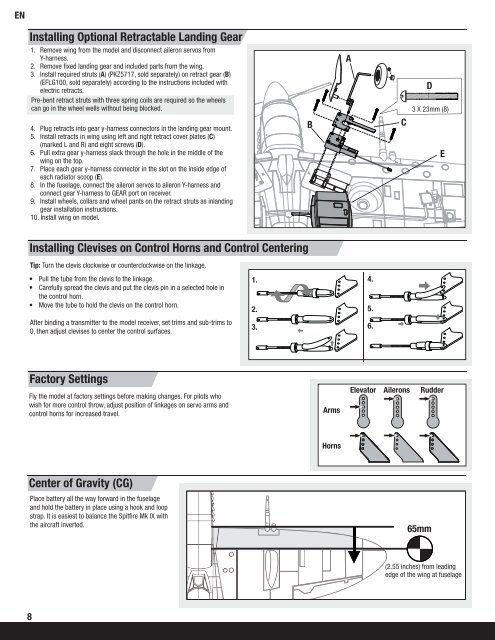
Installing Optional Retractable Landing Gear<br />
1. Remove wing from the model and disconnect aileron servos from<br />
Y-harness.<br />
2. Remove fi xed landing gear and included parts from the wing.<br />
3. Install required struts (A) (PKZ5717, sold separately) on retract gear (B)<br />
(EFLG100, sold separately) according to the instructions included with<br />
electric retracts.<br />
Pre-bent retract struts with three spring coils are required so the wheels<br />
can go in the wheel wells without being blocked.<br />
A<br />
D<br />
3 X 23mm (8)<br />
4. Plug retracts into gear y-harness connectors in the landing gear mount.<br />
5. Install retracts in wing using left and right retract cover plates (C)<br />
(marked L and R) and eight screws (D).<br />
6. Pull extra gear y-harness slack through the hole in the middle of the<br />
wing on the top.<br />
7. Place each gear y-harness connector in the slot on the inside edge of<br />
each radiator scoop (E).<br />
8. In the fuselage, connect the aileron servos to aileron Y-harness and<br />
connect gear Y-harness to GEAR port on receiver.<br />
9. Install wheels, collars and wheel pants on the retract struts as inlanding<br />
gear installation instructions.<br />
10. Install wing on model.<br />
B<br />
C<br />
E<br />
Installing Clevises on Control Horns and Control Centering<br />
Tip: Turn the clevis clockwise or counterclockwise on the linkage.<br />
• Pull the tube from the clevis to the linkage.<br />
• Carefully spread the clevis and put the clevis pin in a selected hole in<br />
the control horn.<br />
• Move the tube to hold the clevis on the control horn.<br />
1. 4.<br />
2.<br />
5.<br />
After binding a transmitter to the model receiver, set trims and sub-trims to<br />
0, then adjust clevises to center the control surfaces.<br />
3.<br />
6.<br />
Factory Settings<br />
Fly the model at factory settings before making changes. For pilots who<br />
wish for more control throw, adjust position of linkages on servo arms and<br />
control horns for increased travel.<br />
Arms<br />
Elevator<br />
Ailerons<br />
Rudder<br />
Horns<br />
Center of Gravity (CG)<br />
Place battery all the way forward in the fuselage<br />
and hold the battery in place using a hook and loop<br />
strap. It is easiest to balance the Spitfi re Mk <strong>IX</strong> with<br />
the aircraft inverted.<br />
65mm<br />
(2.55 inches) from leading<br />
edge of the wing at fuselage<br />
8