DuraMAR 5915 - Parvus Corporation
DuraMAR 5915 - Parvus Corporation
DuraMAR 5915 - Parvus Corporation

You also want an ePaper? Increase the reach of your titles
YUMPU automatically turns print PDFs into web optimized ePapers that Google loves.
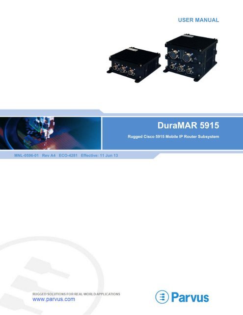
USER MANUAL<br />
<strong>DuraMAR</strong> <strong>5915</strong><br />
Rugged Cisco <strong>5915</strong> Mobile IP Router Subsystem<br />
MNL-0596-01 Rev A4 ECO-4281 Effective: 11 Jun 13
<strong>DuraMAR</strong> <strong>5915</strong> User Manual<br />
Disclaimer<br />
Although the information contained herein has been carefully verified, <strong>Parvus</strong> <strong>Corporation</strong> assumes no responsibility for errors that<br />
might appear in this document or for damage to property or persons resulting from improper use of this manual or related software.<br />
<strong>Parvus</strong> reserves the right to change the contents and form of this document, as well as the features and specifications of its<br />
products, at any time without notice. The information in this publication does not represent a commitment on the part of <strong>Parvus</strong>. This<br />
document contains proprietary information that is protected by copyright. All rights are reserved. No part of this document may be<br />
photocopied, reproduced, or translated into another language without the prior written consent of <strong>Parvus</strong>.<br />
Contact Information<br />
<strong>Parvus</strong> <strong>Corporation</strong><br />
3222 S. Washington St.<br />
Salt Lake City, Utah, USA 84115<br />
Phone: +1 (801) 483-1533<br />
Toll-Free: +1 (800) 483-3152<br />
Fax: +1 (801) 483-1523<br />
Email:<br />
Sales: sales@parvus.com<br />
Support: tsupport@parvus.com<br />
Web-site: http://www.parvus.com<br />
Send us your comments and feedback: feedback@parvus.com<br />
<strong>Parvus</strong> is a U.S. subsidiary of the Eurotech Group (www.eurotech.com), a global family of technology companies focused on<br />
innovative embedded and high performance computing solutions.<br />
Trademarks<br />
All trademarks, both marked and not marked, appearing in this document are the property of their respective owners.<br />
Copyright<br />
© 2011 <strong>Parvus</strong> <strong>Corporation</strong><br />
Page 2 of 56 MNL-0596-01 Rev A4 ECO-4281 11 Jun 13
<strong>DuraMAR</strong> <strong>5915</strong> User Manual<br />
Table of Contents<br />
Chapter 1 Introduction ............................................................................................................. 7<br />
About This Document .................................................................................................................................... 7<br />
Manual Organization .............................................................................................................................. 7<br />
Description of Safety Symbols ................................................................................................................ 8<br />
Overview ....................................................................................................................................................... 9<br />
Features ................................................................................................................................................ 10<br />
Cisco Technology ........................................................................................................................... 10<br />
Scalability ....................................................................................................................................... 10<br />
Ruggedization ................................................................................................................................ 10<br />
Functional Description ................................................................................................................................. 11<br />
Configurations ....................................................................................................................................... 11<br />
Base Module ......................................................................................................................................... 11<br />
Expansion Modules .............................................................................................................................. 12<br />
Cisco <strong>5915</strong> Router ................................................................................................................................ 12<br />
<strong>Parvus</strong> Power Supply ........................................................................................................................... 13<br />
Chapter 2 Operating Description ........................................................................................... 14<br />
Cable and Connector Identification ............................................................................................................. 14<br />
Starter Cableset for Base Module ........................................................................................................ 14<br />
Base Module Connectors and LEDs .................................................................................................... 15<br />
Mounting the System ............................................................................................................................ 16<br />
Basic Operating Procedures ....................................................................................................................... 16<br />
Starting the Cisco Console ................................................................................................................... 16<br />
Zeroization ............................................................................................................................................ 17<br />
Initiating Zeroization ....................................................................................................................... 17<br />
Zeroization Recovery ..................................................................................................................... 17<br />
Loading Cisco Files ..................................................................................................................................... 18<br />
Command Conventions ........................................................................................................................ 18<br />
Loading the IOS Image After Zeroization ............................................................................................. 18<br />
Host PC Setup ............................................................................................................................... 18<br />
Load Procedure .............................................................................................................................. 18<br />
Loading the IOS Configuration After Zeroization .................................................................................. 19<br />
Upgrading to a New IOS Image ............................................................................................................ 20<br />
Host PC Setup ............................................................................................................................... 20<br />
Upgrade Procedure ........................................................................................................................ 20<br />
Chapter 3 Connector Descriptions ........................................................................................ 21<br />
Connector Identification ........................................................................................................................ 21<br />
J1 Power Connector Pinouts ................................................................................................................ 21<br />
J2 Ethernet 0 Connector Pinouts .......................................................................................................... 22<br />
<strong>5915</strong>-0x Ethernet Connector Pinout ............................................................................................... 22<br />
<strong>5915</strong>-1x Connector Pinout ............................................................................................................. 23<br />
J3 Console Connector Pinouts ............................................................................................................. 24<br />
Chapter 4 Specifications ........................................................................................................ 25<br />
Chassis ........................................................................................................................................................ 25<br />
Physical Specifications ......................................................................................................................... 25<br />
Dimensions ........................................................................................................................................... 25<br />
Standalone Router Dimensions ..................................................................................................... 26<br />
MNL-0596-01 Rev A4 ECO-4281 Effective: 11 Jun 13 Page 3 of 56
<strong>DuraMAR</strong> <strong>5915</strong> User Manual<br />
Router with Expansion Module Dimensions .................................................................................. 29<br />
Mounting Instructions ........................................................................................................................... 33<br />
<strong>5915</strong> Router Specifications ......................................................................................................................... 34<br />
Cisco Technology ................................................................................................................................. 34<br />
Ports ..................................................................................................................................................... 34<br />
Management and Monitoring ................................................................................................................ 34<br />
Voice Support ....................................................................................................................................... 34<br />
Routing/Bridging ................................................................................................................................... 34<br />
Security ................................................................................................................................................. 35<br />
Information Assurance .......................................................................................................................... 35<br />
QoS ....................................................................................................................................................... 35<br />
Status Indication ................................................................................................................................... 35<br />
Power .................................................................................................................................................... 35<br />
Environmental ....................................................................................................................................... 36<br />
EMI/EMC .............................................................................................................................................. 36<br />
Reliability .............................................................................................................................................. 36<br />
Chapter 5 Troubleshooting .................................................................................................... 37<br />
Product Identification ................................................................................................................................... 37<br />
Technical Assistance .................................................................................................................................. 37<br />
Returning for Service .................................................................................................................................. 37<br />
Chapter 6 Contact Info ........................................................................................................... 38<br />
Expansion Module ....................................................................................................... 39<br />
Addendum A: Gigabit Ethernet Switches ................................................................ 39<br />
A1 Introduction ....................................................................................................................... 40<br />
About This Document .................................................................................................................................. 40<br />
COM-1268 Manuals ............................................................................................................................. 40<br />
Addendum Organization ....................................................................................................................... 40<br />
Overview ..................................................................................................................................................... 41<br />
Features ................................................................................................................................................ 41<br />
Scalability ....................................................................................................................................... 41<br />
Ruggedization ................................................................................................................................ 41<br />
Functional Description ................................................................................................................................. 42<br />
Configurations ....................................................................................................................................... 42<br />
Block Diagram ...................................................................................................................................... 42<br />
Internal Ethernet Connections .............................................................................................................. 43<br />
A2 Operational Description .................................................................................................... 44<br />
Cables and Connectors ............................................................................................................................... 44<br />
1268 EM Starter Cableset .................................................................................................................... 44<br />
COM-1268 EM Connectors and LEDs ................................................................................................. 45<br />
Basic Operating Procedures ....................................................................................................................... 46<br />
Console Session Setup ........................................................................................................................ 46<br />
Zeroization ............................................................................................................................................ 46<br />
Initiating Zeroization ....................................................................................................................... 46<br />
Zeroization Recovery ..................................................................................................................... 46<br />
A3 Connector Descriptions .................................................................................................... 47<br />
Connector Identification ........................................................................................................................ 47<br />
Page 4 of 56 MNL-0596-01 Rev A4 ECO-4281 11 Jun 13
<strong>DuraMAR</strong> <strong>5915</strong> User Manual<br />
COM-1268 Port Numbers ..................................................................................................................... 47<br />
J4 Ethernet 1 Connector Pinouts .......................................................................................................... 48<br />
J5 Ethernet 2 Connector Pinouts .......................................................................................................... 50<br />
A4 Specifications .................................................................................................................... 52<br />
Physical Specifications ................................................................................................................................ 52<br />
Size ....................................................................................................................................................... 52<br />
Power .................................................................................................................................................... 52<br />
Status Indication ................................................................................................................................... 52<br />
Ports ..................................................................................................................................................... 52<br />
Technical Specifications .............................................................................................................................. 52<br />
Switching Architecture .......................................................................................................................... 52<br />
Port Features ........................................................................................................................................ 53<br />
Management and Monitoring ................................................................................................................ 53<br />
Declassification ..................................................................................................................................... 53<br />
Protocol Standards ...................................................................................................................................... 54<br />
MNL-0596-01 Rev A4 ECO-4281 Effective: 11 Jun 13 Page 5 of 56
<strong>DuraMAR</strong> <strong>5915</strong> User Manual<br />
List of Figures<br />
Figure 1. Standalone Router (MAR-<strong>5915</strong>-0x) .............................................................................................. 9<br />
Figure 2. Router with Expansion Module (MAR-<strong>5915</strong>-1x) ........................................................................... 9<br />
Figure 3. Standalone Router Block Diagram ............................................................................................. 11<br />
Figure 4. Router with Expansion Module Block Diagram (example) ......................................................... 12<br />
Figure 5. Base Module Starter Cableset (CBL-<strong>5915</strong>-00) ........................................................................... 14<br />
Figure 6. Base Module Connectors and LEDs .......................................................................................... 15<br />
Figure 7. J2 LED Mapping to J2 Signal Name and Cisco Port Name ....................................................... 15<br />
Figure 8. Connector J1 Power ................................................................................................................... 21<br />
Figure 9. Connector J2 Ethernet 0 ............................................................................................................. 22<br />
Figure 10. Connector J3 Console .............................................................................................................. 24<br />
Figure 11. Standalone Router Angle View ................................................................................................. 26<br />
Figure 12. Standalone Router Front View .................................................................................................. 26<br />
Figure 13. Standalone Router Top View .................................................................................................... 27<br />
Figure 14. Standalone Router Side View ................................................................................................... 28<br />
Figure 15. Router with EM Angle View ...................................................................................................... 29<br />
Figure 16. Router with EM Front View ....................................................................................................... 30<br />
Figure 17. Router with EM Top View ......................................................................................................... 31<br />
Figure 18. Router with EM Side View ........................................................................................................ 32<br />
Figure 19. Standalone Router Side Boss Mounting ................................................................................... 33<br />
Figure 20. Router with Expansion Module Side Boss Mounting ................................................................ 33<br />
Figure 21. Router Back View Showing Optional Grounding Boss Location .............................................. 33<br />
Figure 22. MAR-<strong>5915</strong>-1x with Integrated COM-1268 EM .......................................................................... 41<br />
Figure 23. Router with COM-1268 EM Block Diagram .............................................................................. 42<br />
Figure 24. 1268 EM Internal Connections ................................................................................................. 43<br />
Figure 25. 1268 EM Starter Cableset (CBL-<strong>5915</strong>-01) ............................................................................... 44<br />
Figure 26. COM-1268 EM Connectors and LEDs ..................................................................................... 45<br />
Figure 27. Connector J4 Ethernet 1 ........................................................................................................... 48<br />
Figure 28. Connector J5 Ethernet 2 ........................................................................................................... 50<br />
Page 6 of 56 MNL-0596-01 Rev A4 ECO-4281 11 Jun 13
<strong>DuraMAR</strong> <strong>5915</strong> User Manual Chapter 1 Introduction<br />
Chapter 1 Introduction<br />
The <strong>DuraMAR</strong>® <strong>5915</strong> is a rugged Commercial-Off the Shelf (COTS) Cisco IOS-managed mobile router<br />
integrated with Cisco’s <strong>5915</strong> Embedded Services Router (ESR) card in an ultra-rugged chassis optimized<br />
for harsh military and civil vehicle/aircraft installations. The <strong>DuraMAR</strong> <strong>5915</strong> is currently available as either<br />
a standalone 5-port network router or with the <strong>Parvus</strong> Dual Gigabit Ethernet Switches (COM-1268s)<br />
expansion module integrated into a common chassis. Additional expansion modules that offer differing<br />
functionality are currently under development. For details, contact the <strong>Parvus</strong> Sales department.<br />
About This Document<br />
This manual provides a functional description of the <strong>DuraMAR</strong> <strong>5915</strong>, both as a standalone Cisco <strong>5915</strong><br />
router and with expansion modules.<br />
Note: This manual is not a comprehensive guide to the Cisco <strong>5915</strong> or IOS. That information is<br />
available directly from Cisco Systems at www.cisco.com.<br />
Manual Organization<br />
Chapters 1 through 6, the base manual, cover the MAR-<strong>5915</strong>-0x base router, which includes the Cisco<br />
<strong>5915</strong>, chassis, and <strong>Parvus</strong> power supply.<br />
<br />
<br />
<br />
<br />
Chapter 1 provides a functional description of the <strong>DuraMAR</strong> <strong>5915</strong>, and explains how expansion<br />
modules are integrated with the Cisco <strong>5915</strong> in a common chassis.<br />
Chapter 2 explains how to operate the base router. It describes the cables, connectors, and<br />
LEDs, and includes procedures for starting the Cisco console, performing zeroization, and<br />
loading Cisco files.<br />
Chapter 3 contains connector pinouts for the base module.<br />
Chapter 4 provides chassis specifications, dimensions, and mounting instructions for all<br />
<strong>DuraMAR</strong> <strong>5915</strong> modules. In addition, it provides the specifications for the Cisco <strong>5915</strong> router.<br />
Chapters 5 and 6 provide troubleshooting and <strong>Parvus</strong> contact information, and apply to all<br />
<strong>DuraMAR</strong> <strong>5915</strong> modules.<br />
Each expansion module (EM) is described in a separate addendum that follows the same general<br />
organization as the base manual. Chapters in the addendum are identified by the addendum letter; for<br />
example, "A3 Connector Descriptions."<br />
<br />
Addendum A describes MAR-<strong>5915</strong>-1x, the <strong>Parvus</strong> Dual Gigabit Ethernet Switches (COM-1268s)<br />
expansion module, referred to as the COM-1268 EM.<br />
MNL-0596-01 Rev A4 ECO-4281 Effective: 11 Jun 13 Page 7 of 56
Chapter 1 Introduction<br />
<strong>DuraMAR</strong> <strong>5915</strong> User Manual<br />
Description of Safety Symbols<br />
The following safety symbols are used in this manual and indicate potentially dangerous situations.<br />
Warning! Danger, electrical shock hazard!<br />
Personal injury or death could occur. Also damage to the system, connected peripheral devices, or<br />
software could occur if the warnings are not followed carefully.<br />
Caution! Hazard to individuals, environment, devices, or data!<br />
If you do not adhere to the safety advice next to this symbol, there is obvious hazard to individuals, to<br />
environment, to materials, or to data.<br />
Note: This symbol highlights important information or instructions that should be observed.<br />
Page 8 of 56 MNL-0596-01 Rev A4 ECO-4281 11 Jun 13
<strong>DuraMAR</strong> <strong>5915</strong> User Manual Chapter 1 Introduction<br />
Overview<br />
The <strong>DuraMAR</strong>® <strong>5915</strong> is a rugged Commercial-Off-the-Shelf (COTS) Cisco IOS-managed mobile router<br />
integrated with Cisco’s <strong>5915</strong> Embedded Services Router (ESR) card in an ultra-rugged chassis optimized<br />
for harsh military and civil vehicle/aircraft installations. The <strong>DuraMAR</strong> <strong>5915</strong> is an ideal solution for IP<br />
networking technology refresh and situational awareness applications, including those seeking a<br />
migration path for legacy Cisco 3200 (3230/3250/3270)-based router subsystems.<br />
Optimized for Size, Weight and Power (SWaP) sensitivity as well as mechanical robustness under<br />
extreme environmental conditions per MIL-STD-810G (thermal, shock, vibration, humidity, exposure to<br />
dust, water), the <strong>DuraMAR</strong> <strong>5915</strong> enables prime contractors and civilian agencies to deploy Cisco Mobile<br />
Ready Net capabilities, including data, video, and voice services virtually anywhere LAN or WAN<br />
connectivity may be required, especially in mobile, airborne, ground, manned or unmanned vehicle<br />
applications.<br />
Leveraging stackable PC/104 subassemblies and a modular enclosure design, the unit is completely<br />
sealed, requires no active cooling, provides interfaces over MIL-C-38999 style connectors, and features a<br />
military-grade power supply supporting aircraft (MIL-STD-704F) and ground/marine (MIL-STD-1275D)<br />
vehicle voltage inputs, spikes, and transient levels, as well as MIL-STD-461F EMI/EMC filtering.<br />
The <strong>DuraMAR</strong> <strong>5915</strong> features dual WAN uplinks and is available as either:<br />
A standalone 5-port network router (Figure 1)<br />
<br />
The base router with one or more expansion modules (EM) factory-installed, such as the<br />
integrated <strong>Parvus</strong> Dual Gigabit Ethernet Switches (COM-1268s EM) (Figure 2)<br />
Figure 1. Standalone Router<br />
(MAR-<strong>5915</strong>-0x)<br />
Figure 2. Router with Expansion Module<br />
(MAR-<strong>5915</strong>-1x)<br />
With software built upon the Cisco 3270 IOS architecture, the <strong>DuraMAR</strong> <strong>5915</strong> delivers the performance,<br />
security, advanced Quality of Service (QoS), high availability, and manageability that customers expect<br />
from Enterprise IOS-based routing technology. The unit supports extensive IPv4 and IPv6 routing<br />
protocols, IP multicasting, Radio Aware Routing (RAR), Dynamic Link Exchange Protocol (DLEP) and<br />
Mobile IP routing for transparent connectivity to a roaming vehicle network in Comms-on-the-Move<br />
(COTM) applications. An onboard AES hardware encryption engine offloads encryption processing from<br />
the router to provide highly secure yet scalable data, video, and voice services.<br />
MNL-0596-01 Rev A4 ECO-4281 Effective: 11 Jun 13 Page 9 of 56
Chapter 1 Introduction<br />
<strong>DuraMAR</strong> <strong>5915</strong> User Manual<br />
Features<br />
Cisco Technology<br />
Ruggedized Cisco <strong>5915</strong> Router with Enterprise IOS Software for robust security, management,<br />
QoS, VLAN, IPv4/IPv6 routing, IP mobility, interoperability<br />
<br />
Integrated Services Router (ISR) features support concurrent data, video, and voice services, as<br />
well as firewall and hardware AES encryption acceleration<br />
Scalability<br />
Modular, open-architecture rugged COTS PC/104 hardware design<br />
<br />
<br />
<br />
Standalone Router provides 5 Ethernet ports (3x 10/100 switched, 2x 10/100 routed)<br />
Router plus COM-1268 EM provides integrated <strong>Parvus</strong> Dual Gigabit Ethernet Switches (two<br />
COM-1268s).<br />
Scales port density to 19 Ethernet ports for higher-port-density application requirements<br />
<br />
Provides 19 Ethernet ports total (15 GigE switched, 2x 10/100 switched, 2x 10/100 routed)<br />
Additional expansion modules upon request<br />
Ruggedization<br />
<br />
<br />
<br />
<br />
<br />
<br />
<br />
<br />
<br />
Qualified to MIL-STD-810G Shock, Vibration, Thermal, Altitude, Humidity<br />
-40 to +71C fanless extended temperature operation with no moving parts<br />
Corrosion-resistant, aluminum chassis sealed against water, dust, EMI<br />
Circular MIL-DTL-38999 connectors for reliable network connections<br />
Filtered, transient-protected power supply for aircraft and vehicle use<br />
Qualified to MIL-STD-461F Conducted/Radiated Emissions and Conducted/Radiated<br />
Susceptibility<br />
Data Zeroization support to erase sensitive information<br />
Conformal coating for humidity/tin-whisker mitigation<br />
Flexible, robust mounting – base flange mount or side boss mount<br />
Page 10 of 56 MNL-0596-01 Rev A4 ECO-4281 11 Jun 13
<strong>DuraMAR</strong> <strong>5915</strong> User Manual Chapter 1 Introduction<br />
Functional Description<br />
Configurations<br />
Product<br />
Product<br />
Number<br />
Base<br />
Enterprise<br />
IOS<br />
Advanced<br />
Enterprise IOS<br />
Standalone Router MAR-<strong>5915</strong>-0x -00 -01, -02*, -03**,-<br />
04***<br />
Base Router with<br />
Dual Gigabit<br />
Ethernet Switches<br />
(COM-1268s)<br />
MAR-<strong>5915</strong>-1x -10 -11, -12*, -13**,-<br />
14***<br />
Breakout<br />
Cableset<br />
CBL-<strong>5915</strong>-00<br />
CBL-<strong>5915</strong>-01<br />
Description<br />
<strong>DuraMAR</strong> <strong>5915</strong> Mobile Router<br />
2x FE routed ports<br />
3x FE switched ports<br />
<strong>DuraMAR</strong> <strong>5915</strong> Mobile Router<br />
with COM-1268 EM<br />
2x FE routed ports<br />
2x FE switched ports<br />
15x GigE switched ports<br />
* CME-5 Users<br />
** CME-25 Users<br />
** CME-50 Users<br />
Base Module<br />
The base module of the <strong>DuraMAR</strong> <strong>5915</strong> contains the Cisco <strong>5915</strong> Router and the <strong>Parvus</strong> Power Supply<br />
(Figure 3). It is available as a standalone router (MAR-<strong>5915</strong>-0x) or as the bottom module with expansion<br />
modules, such as the MAR-<strong>5915</strong>-1x (Figure 4).<br />
Figure 3. Standalone Router Block Diagram<br />
<br />
<br />
<br />
The <strong>Parvus</strong> Power Supply provides power for the Cisco <strong>5915</strong> and for boards in the expansion<br />
modules (if any).<br />
The internal Ethernet connection connects the Cisco <strong>5915</strong> to Ethernet boards in the expansion<br />
module. When expansion modules are connected to the Cisco <strong>5915</strong>, Cisco port 0/4 is used for<br />
communication between modules.<br />
The Zeroization signal is externally generated at the J3 Console connector and transmitted to<br />
the Cisco <strong>5915</strong> and to boards in the expansion modules. See "Zeroization" on page 17 for more<br />
details.<br />
MNL-0596-01 Rev A4 ECO-4281 Effective: 11 Jun 13 Page 11 of 56
Chapter 1 Introduction<br />
<strong>DuraMAR</strong> <strong>5915</strong> User Manual<br />
Expansion Modules<br />
In expansion module configurations, additional boards are added to the stack, the chassis height is<br />
increased, and the EM front panel is customized with unique connectors and LEDs appropriate for the<br />
functionality of the boards in that module. Figure 4 shows a typical expansion module configuration<br />
(MAR-<strong>5915</strong>-1x): the Base Router Module with the Dual Gigabit Ethernet Switch (COM-1268) Expansion<br />
Module, which contains two <strong>Parvus</strong> COM-1268 boards. Refer to the EM addenda at the end of this<br />
manual for detailed expansion module information.<br />
Figure 4. Router with Expansion Module Block Diagram (example)<br />
Cisco <strong>5915</strong> Router<br />
Refer to Cisco documentation at www.cisco.com for a functional description of the router.<br />
Page 12 of 56 MNL-0596-01 Rev A4 ECO-4281 11 Jun 13
<strong>DuraMAR</strong> <strong>5915</strong> User Manual Chapter 1 Introduction<br />
<strong>Parvus</strong> Power Supply<br />
The bottom board in the base module is a <strong>Parvus</strong> power supply. The rugged, isolated power supply is<br />
capable of supplying power output over extended temperature ranges (-40 to +85C per MIL-STD-810G).<br />
Featuring a rugged mechanical design, this small form-factor power supply is designed to operate without<br />
any active cooling and provide resistance to high levels of shock and vibration.<br />
Features<br />
Uses 28V nominal power input voltage (18-33VDC range continuous).<br />
<strong>DuraMAR</strong> <strong>5915</strong>-0x power consumption: designed for
Chapter 2 Operating Description<br />
<strong>DuraMAR</strong> <strong>5915</strong> User Manual<br />
Chapter 2 Operating Description<br />
This chapter describes the operation of the <strong>DuraMAR</strong> <strong>5915</strong> base module. This information applies both<br />
to the standalone router and to the base module with expansion modules.<br />
Cable and Connector Identification<br />
Starter Cableset for Base Module<br />
You should test the <strong>DuraMAR</strong> <strong>5915</strong> and cabling or interfaces prior to installation in the target system to<br />
ensure full operational capability. Full bench-top testing can be performed by using the <strong>Parvus</strong> starter<br />
cableset available for this unit or by using a custom set of cables made specifically for the intended target<br />
system, vehicle, or craft. Refer to Chapter 3 for pinouts and descriptions.<br />
The <strong>Parvus</strong> starter cableset (CBL-<strong>5915</strong>-00) for the base module is available for purchase through the<br />
<strong>Parvus</strong> Sales department and is meant for lab or bench testing purposes only. The cables provide<br />
access to connectors J1-J3.<br />
Figure 5. Base Module Starter Cableset (CBL-<strong>5915</strong>-00)<br />
The starter cableset for the base module has the following MIL-C-38999 connectors.<br />
Part # Type Quantity Description<br />
CBL-2417-01 Banana Plugs 3 each J1 Power<br />
CBL-2418-01 RJ-45 Connectors 5 each J2 Ports 0-4<br />
CBL-2419-01<br />
J3 Console. Cable with two tails (flying leads and DB9) for<br />
attachment to the host PC.<br />
DB9 1 each Serial connection to J3 Management Port<br />
Yellow Wire 1 each J3 Pin 2, Zeroize<br />
Green Wire 1 each J3 Pin 1, ground reference for the +12VDC signal<br />
Page 14 of 56 MNL-0596-01 Rev A4 ECO-4281 11 Jun 13
<strong>DuraMAR</strong> <strong>5915</strong> User Manual Chapter 2 Operating Description<br />
Base Module Connectors and LEDs<br />
Figure 6 shows the connectors and LEDs on the base module front panel.<br />
Figure 6. Base Module Connectors and LEDs<br />
The table describes the LEDs on the front panel of the base module.<br />
LED Component Description<br />
PWR System power supply Blue light indicates power is on.<br />
SYS Cisco <strong>5915</strong> Router Blinking green light indicates the boot-up phase or ROMMON monitor<br />
mode of the Cisco router.<br />
R0, R1 Routed Ethernet ports 0/0 and<br />
0/1 on connector J2<br />
S0, S1, S2 Switched Ethernet ports 0/2,<br />
0/3, and 0/4 on connector J2<br />
<br />
Steady green light indicates steady state, IOS load completed and<br />
running.<br />
Steady green light indicates link status.<br />
Steady green light indicates link status.<br />
Figure 7 shows the mapping of Cisco port names to J2 signal names and to the LED labels on the front<br />
panel.<br />
Figure 7. J2 LED Mapping to J2 Signal Name and Cisco Port Name<br />
Note: In expansion module configurations (e.g., MAR-<strong>5915</strong>-1x), port 0/4 is used internally for<br />
Ethernet connection to boards in the EM(s), and LED S2 is green when there is a valid Ethernet<br />
connection to the EM(s).<br />
MNL-0596-01 Rev A4 ECO-4281 Effective: 11 Jun 13 Page 15 of 56
Chapter 2 Operating Description<br />
<strong>DuraMAR</strong> <strong>5915</strong> User Manual<br />
Mounting the System<br />
After testing is complete, you can mount the <strong>DuraMAR</strong> <strong>5915</strong> on the system. Refer to the instructions and<br />
dimensions in Chapter 4.<br />
Basic Operating Procedures<br />
This section describes basic operating procedures, including starting the system console, zeroizing the<br />
system, and reloading files after zeroization.<br />
Starting the Cisco Console<br />
1. Connect the console cable (CBL-2419-01) or a customer-designed cable to a host PC serial port and<br />
to connector J3 on the <strong>DuraMAR</strong> <strong>5915</strong>.<br />
2. Connect the power cable (CBL-2417-01) or a customer-designed power cable to connector J1 on the<br />
<strong>DuraMAR</strong> <strong>5915</strong> and to a 18-33VDC power source.<br />
3. Open a terminal emulator on the host PC. For example, if you are running Windows XP, click:<br />
Start > All Programs > Accessories > Communications > HyperTerminal<br />
4. Select the host COM port that is connected to the <strong>DuraMAR</strong> <strong>5915</strong>.<br />
5. Create a new terminal connection that has the following settings:<br />
Bits per second 9600<br />
Data bits 8<br />
Parity<br />
None<br />
Stop bits 1<br />
Flow control<br />
None<br />
6. Apply power (18-33 VDC) to the <strong>DuraMAR</strong> <strong>5915</strong>.<br />
7. The Cisco Router bootup information is displayed on the console screen.<br />
8. After bootup, press Enter to get to the Router> prompt.<br />
<br />
To configure the Cisco <strong>5915</strong> Router, refer to Cisco documentation.<br />
Page 16 of 56 MNL-0596-01 Rev A4 ECO-4281 11 Jun 13
<strong>DuraMAR</strong> <strong>5915</strong> User Manual Chapter 2 Operating Description<br />
Zeroization<br />
For data security, the <strong>DuraMAR</strong> <strong>5915</strong> provides zeroization capability to erase the application code and<br />
configuration data stored in the system. Refer to the Cisco documentation on how to configure the <strong>5915</strong><br />
for zeroization. Once the code is erased, the only method of recovery is to reload code to the system.<br />
Enabling Zeroization in Cisco <strong>5915</strong> IOS<br />
Prior to applying the zeroization signal, the Cisco IOS must be configured to enable the zeroization.<br />
<br />
From an IOS prompt, enter the following commands:<br />
Router> enable<br />
Router# conf t<br />
Router(config)# service declassify erase-all<br />
Router(config)# exit<br />
<br />
<br />
The “erase-all” argument will erase all files on the router (flash and NVRAM) when<br />
declassification (zeroization) is invoked<br />
“erase-flash” or “erase-nvram” may be substituted for “erase-all” if only the files in flash memory<br />
or NVRAM, respectively, are to be deleted.<br />
Initiating Zeroization<br />
The hardware setup must generate the off-board Zeroization trigger.<br />
If you have CBL-2419-01, use the yellow wire and apply a +12VDC signal pulse to J3 pin 2. The<br />
green wire is the ground reference for the +12VDC signal.<br />
If you do not have the starter cable, apply a +12VDC signal pulse to J3 pin 2.<br />
Caution!<br />
Do not apply +12VDC to any other pin. +12VDC must be relative to signal ground (J3 pin 1), not input<br />
power ground.<br />
Zeroization Recovery<br />
After zeroization has been completed (about 5 minutes), perform the following steps to reload the system.<br />
1. Start the Cisco console. Reload the Cisco <strong>5915</strong> IOS (refer to the instructions in the next section).<br />
2. Reload the Cisco <strong>5915</strong> configuration. Refer to the instructions in the next section.<br />
3. If your system contains an expansion module that supports zeroization (such as the COM-1268 EM),<br />
you'll need to perform recovery for those boards. Refer to the addendum for your expansion module<br />
for instructions on zeroization recovery.<br />
MNL-0596-01 Rev A4 ECO-4281 Effective: 11 Jun 13 Page 17 of 56
Chapter 2 Operating Description<br />
<strong>DuraMAR</strong> <strong>5915</strong> User Manual<br />
Loading Cisco Files<br />
This section explains how to load Cisco application and configuration files to the Cisco <strong>5915</strong>. It covers<br />
two cases: reloading after zeroization and upgrading to a new version.<br />
This manual is not intended as a comprehensive guide to the Cisco <strong>5915</strong> or IOS. That information is<br />
available directly from Cisco Systems at www.cisco.com. The Cisco website is also your source for Cisco<br />
files.<br />
Command Conventions<br />
<br />
<br />
<br />
Commands and arguments you must type are shown in bold.<br />
After you type the command, press the Enter key.<br />
If several command lines are presented in one step, press Enter after each line.<br />
Loading the IOS Image After Zeroization<br />
Host PC Setup<br />
1. Start the Cisco console.<br />
2. Identify the target folder used by the tftp server and place the Cisco IOS software image there. The<br />
<strong>DuraMAR</strong> <strong>5915</strong> ships with a factory default Cisco IOS version of:<br />
c<strong>5915</strong>-entbase-mz.SPA.152-1.GC1.bin<br />
3. Place the configuration file to be reloaded (c<strong>5915</strong>-entbase-mz.SPA.152-1.GC1.bin or other) in the tftp<br />
target folder.<br />
4. Attach the host PC to port 0/0 on J2. (This can be the same PC as that running the terminal<br />
emulator.)<br />
5. Set the IP address of the host PC to use the fixed address 192.168.100.11.<br />
6. Open the tftp server on the host PC.<br />
A note on this: The Solarwinds TFTP server has a file transfer size limit of 32 MB. This is<br />
not a problem for the base IOS identified here. But if the c<strong>5915</strong>-adventerprisek9-<br />
mz.SPA.152-1.GC1.bin or another file in excess of 32 MB is transferred, the file is too large<br />
for Solarwinds. The TFTPD32 TFTP server handles the larger file size without a problem.<br />
Load Procedure<br />
There should be a rommon prompt in the terminal emulator window. If the rommon prompt is not<br />
displayed, reboot the <strong>DuraMAR</strong> <strong>5915</strong> and wait for the rommon prompt.<br />
1. At the rommon command prompt, type the following CASE-SENSITIVE commands (press Enter after<br />
each command, the filename itself is NOT case-sensitive):<br />
IP_ADDRESS=192.168.100.10<br />
IP_SUBNET_MASK=255.255.255.0<br />
DEFAULT_GATEWAY=192.168.100.11<br />
TFTP_SERVER=192.168.100.11<br />
TFTP_FILE=c<strong>5915</strong>-entbase-mz.SPA.152-1.GC1.bin<br />
2. At the rommon command prompt, type “set” and Enter. Verify the variables in step 1 have been set<br />
correctly.<br />
3. At the rommon command prompt, type the following CASE-SENSITIVE command and Enter:<br />
Page 18 of 56 MNL-0596-01 Rev A4 ECO-4281 11 Jun 13
<strong>DuraMAR</strong> <strong>5915</strong> User Manual Chapter 2 Operating Description<br />
tftpdnld<br />
4. At the prompt: “Do you wish to continue y/n: [n],” type y.<br />
5. The IOS will begin transferring to the Cisco <strong>5915</strong>. If the transfer does not begin, a message will be<br />
displayed explaining the problem. Fix the problem and repeat the tftpdnld command.<br />
6. When the file transfer is completed, issue a reset command at the rommon prompt.<br />
7. The Cisco <strong>5915</strong> will then reboot and load. After the Cisco <strong>5915</strong> has finished the startup sequence,<br />
press Enter to display the Router> prompt. The Cisco IOS has been successfully reloaded.<br />
8. Now follow the instructions in the next section to reload the IOS configuration.<br />
Loading the IOS Configuration After Zeroization<br />
After zeroization, you have to reload the IOS configuration file that enables communication between the<br />
Cisco boards and the COM-1268s. In these instructions, filename is the name of the IOS configuration<br />
file saved on the host PC, such as <strong>5915</strong>config.bin. If you are using a different file, use that filename in the<br />
steps below.<br />
1. Set the router port IP address:<br />
Router> enable<br />
Router# conf t<br />
Router(config)# Interf fast 0/0<br />
Router(config-if)# ip address 192.168.100.10 255.255.255.0<br />
Router(config-if)# no shut<br />
Router(config-if)# exit<br />
Router(config)# exit<br />
Router# copy tftp://192.168.100.11/filename startup-config<br />
Destination filename [startup-config] ?<br />
2. Make sure that the [ok- xxxx bytes] message is displayed. If not, fix the error and repeat the copy tftp<br />
command.<br />
3. Power off the system.<br />
4. Power on the system.<br />
5. After the reload completes, press Enter to display a Router> prompt. The Cisco <strong>5915</strong> IOS<br />
configuration has been successfully reloaded.<br />
6. If your <strong>DuraMAR</strong> <strong>5915</strong> includes expansion modules, you may need to perform additional recovery<br />
steps. Refer to "Zeroization Recovery" instructions in each addendum.<br />
MNL-0596-01 Rev A4 ECO-4281 Effective: 11 Jun 13 Page 19 of 56
Chapter 2 Operating Description<br />
<strong>DuraMAR</strong> <strong>5915</strong> User Manual<br />
Upgrading to a New IOS Image<br />
Use these instructions if you are upgrading the IOS to a new version. Go to the Cisco website<br />
www.cisco.com to download the new IOS file.<br />
Host PC Setup<br />
1. Identify the target folder used by the tftp server and place the new Cisco IOS software image there.<br />
2. Attach the host PC to port 0/0 on J2. (This can be the same PC as that running the terminal<br />
emulator.)<br />
3. Set the IP address of the host PC to use the fixed address 192.168.100.11.<br />
4. Open the tftp server on the host PC.<br />
Upgrade Procedure<br />
1. In the terminal emulator window, press Enter to get a Router> prompt.<br />
2. Enter these commands:<br />
Router> enable<br />
Router# show flash:<br />
(Note the old IOS version, such as c<strong>5915</strong>-entbase-mz.SPA.152-1.GC1.bin)<br />
Router# conf t<br />
Router(config)# Interf fast 0/0<br />
Router(config-if)# ip address 192.168.100.10 255.255.255.0<br />
Router(config-if)# no shut<br />
Router(config-if)# exit<br />
Router(config)# exit<br />
(Note: you should verify that there is a valid link from your PC to 0/0 prior to the following command)<br />
Router# delete flash:.bin<br />
where oldIOSversion is the version noted earlier<br />
Delete filename[oldIOSversion.bin ]?<br />
Delete flash:oldIOSversion.bin ? [confirm]<br />
Router# copy tftp://192.168.100.11/ .bin flash:<br />
Destination filename [.bin] ?<br />
X bytes copied in Y secs (Z bytes/sec)<br />
Page 20 of 56 MNL-0596-01 Rev A4 ECO-4281 11 Jun 13
<strong>DuraMAR</strong> <strong>5915</strong> User Manual Chapter 3 Connector Descriptions<br />
Chapter 3 Connector Descriptions<br />
This section identifies the pinouts and signal descriptions for the base module. It also provides connector<br />
part numbers along with suggested mating connector details.<br />
Connector Identification<br />
Connector Label Description Part Number Mating Connector<br />
J1 PWR 18-33 VDC Power Input D38999/20FA98PN D38999/26FA98SN<br />
J2 ETH 0 3X 10/100 Switched, 2X 10/100 Routed for -0x<br />
2X 10/100 Switched, 2X 10/100 Routed for -1x<br />
D38999/20FC35SN<br />
D38999/26FC35PN<br />
J3 CONSOLE RS-232 Console & Zeroize D38999/20FB35SN D38999/26FB35PN<br />
J1 Power Connector Pinouts<br />
J1 provides power input signals for +28V power to the <strong>Parvus</strong> Power Supply.<br />
P/N: D38999/20FA98PN<br />
(Shell Size 9)<br />
Figure 8. Connector J1 Power<br />
J1 Signal Name Description 38999 Pin #<br />
V+ 28 VDC A<br />
V- 28 RTN C<br />
Chassis Chassis B<br />
MNL-0596-01 Rev A4 ECO-4281 Effective: 11 Jun 13 Page 21 of 56
Chapter 3 Connector Descriptions<br />
<strong>DuraMAR</strong> <strong>5915</strong> User Manual<br />
J2 Ethernet 0 Connector Pinouts<br />
J2 provides the signals for the Ethernet ports in the base module. The standalone router has five<br />
Ethernet ports on J2. If the configuration includes any expansion modules, only four ports are available.<br />
Pinouts are provided for each configuration.<br />
Connector Alignment: facing the insert side of the<br />
connector (pin side). The connector on the <strong>DuraMAR</strong><br />
<strong>5915</strong> front panel (socket side) is an exact mirror of the<br />
picture on the left.<br />
P/N: D38999/20FC35SN<br />
(Shell Size 13)<br />
Figure 9. Connector J2 Ethernet 0<br />
<strong>5915</strong>-0x Ethernet Connector Pinout<br />
The standalone router (<strong>5915</strong>-0x) provides three switched and two routed ports. Ports 0 and 1 are the<br />
routed ports; ports 2, 3, and 4 are the switched ports.<br />
J2 Signal Name Description 38999 Pin #<br />
ETH 0_PORT0_TX+ 10/100 TX 0 + 1<br />
ETH 0_PORT0_TX- 10/100 TX 0 - 2<br />
ETH 0_PORT0_RX+ 10/100 RX 0 + 3<br />
ETH 0_PORT0_RX- 10/100 RX 0 - 4<br />
ETH 0_PORT1_TX- 10/100 TX 1 - 5<br />
ETH 0_PORT1_TX+ 10/100 TX 1 + 17<br />
ETH 0_PORT1_RX+ 10/100 RX 1 + 6<br />
ETH 0_PORT1_RX- 10/100 RX 1 - 7<br />
ETH 0_PORT2_TX- 10/100 TX 2 - 8<br />
ETH 0_PORT2_TX+ 10/100 TX 2 + 9<br />
ETH 0_PORT2_RX+ 10/100 RX 2 + 10<br />
ETH 0_PORT2_RX- 10/100 RX 2 - 19<br />
ETH 0_PORT3_TX- 10/100 TX 3 - 11<br />
ETH 0_PORT3_TX+ 10/100 TX 3 + 12<br />
ETH 0_PORT3_RX+ 10/100 RX 3 + 13<br />
ETH 0_PORT3_RX- 10/100 RX 3 - 14<br />
ETH 0_PORT4_TX- 10/100 TX 4 - 15<br />
ETH 0_PORT4_TX+ 10/100 TX 4 + 16<br />
Page 22 of 56 MNL-0596-01 Rev A4 ECO-4281 11 Jun 13
<strong>DuraMAR</strong> <strong>5915</strong> User Manual Chapter 3 Connector Descriptions<br />
J2 Signal Name Description 38999 Pin #<br />
ETH 0_PORT4_RX+ 10/100 RX 4 + 20<br />
ETH 0_PORT4_RX- 10/100 RX 4 - 21<br />
SPARE_11 Populated spare 18<br />
SPARE_12 Populated spare 22<br />
Note: Port 0 TX polarity is opposite of ports 1-4.<br />
<strong>5915</strong>-1x Connector Pinout<br />
With one or more expansion modules, port 4 is used internally for Ethernet connection to the expansion<br />
module boards, and four Ethernet ports are available on J2. Ports 0 and 1 are the routed ports; ports 2<br />
and 3 are the switched ports.<br />
J2 Signal Name Description 38999 Pin #<br />
ETH 0_PORT0_TX+ 10/100 TX 0 + 1<br />
ETH 0_PORT0_TX- 10/100 TX 0 - 2<br />
ETH 0_PORT0_RX+ 10/100 RX 0 + 3<br />
ETH 0_PORT0_RX- 10/100 RX 0 - 4<br />
ETH 0_PORT1_TX- 10/100 TX 1 - 5<br />
ETH 0_PORT1_TX+ 10/100 TX 1 + 17<br />
ETH 0_PORT1_RX+ 10/100 RX 1 + 6<br />
ETH 0_PORT1_RX- 10/100 RX 1 - 7<br />
ETH 0_PORT2_TX- 10/100 TX 2 - 8<br />
ETH 0_PORT2_TX+ 10/100 TX 2 + 9<br />
ETH 0_PORT2_RX+ 10/100 RX 2 + 10<br />
ETH 0_PORT2_RX- 10/100 RX 2 - 19<br />
ETH 0_PORT3_TX- 10/100 TX 3 - 11<br />
ETH 0_PORT3_TX+ 10/100 TX 3 + 12<br />
ETH 0_PORT3_RX+ 10/100 RX 3 + 13<br />
ETH 0_PORT3_RX- 10/100 RX 3 - 14<br />
SPARE_1 Populated spare 15<br />
SPARE_2 Populated spare 16<br />
SPARE_3 Populated spare 20<br />
SPARE_4 Populated spare 21<br />
SPARE_5 Populated spare 18<br />
SPARE_6 Populated spare 22<br />
MNL-0596-01 Rev A4 ECO-4281 Effective: 11 Jun 13 Page 23 of 56
Chapter 3 Connector Descriptions<br />
<strong>DuraMAR</strong> <strong>5915</strong> User Manual<br />
J3 Console Connector Pinouts<br />
J3 is the console connector for the Cisco <strong>5915</strong>.<br />
Connector Alignment: facing the insert side of the<br />
connector (pin side). The connector on the<br />
<strong>DuraMAR</strong> <strong>5915</strong> front panel (socket side) is an exact<br />
mirror of the picture on the left.<br />
P/N: D38999/20FB35SN<br />
(Shell Size 11)<br />
Figure 10. Connector J3 Console<br />
J3 Signal Name Description 38999 Pin #<br />
Zeroize Zeroization of System 2<br />
B-1 GND Signal Ground. Used for zeroization. 1<br />
CONS_TXD_RS232 Console Transmit Data 10<br />
CONS_DTR_RS232 Console Data Terminal Ready 8<br />
CONS_RTS_RS232 Console Ready to Send 9<br />
CONS_RXD_RS232 Console Receive Data 12<br />
CONS_DSR_RS232 Console Data Set Ready 7<br />
CONS_CTS_RS232 Console Clear to Send 13<br />
CON_GND_RS232 Console Ground 11<br />
SPARE_1 Populated spare 3<br />
SPARE_2 Populated spare 4<br />
SPARE_3 Populated spare 5<br />
SPARE_4 Populated spare 6<br />
Page 24 of 56 MNL-0596-01 Rev A4 ECO-4281 11 Jun 13
<strong>DuraMAR</strong> <strong>5915</strong> User Manual Chapter 4 Specifications<br />
Chapter 4 Specifications<br />
This chapter provides specifications for the <strong>DuraMAR</strong> <strong>5915</strong> chassis and Cisco <strong>5915</strong> Router.<br />
Chassis<br />
Physical Specifications<br />
<br />
<br />
<br />
<br />
<br />
Weight: 4.0 lbs. (1.81 kg) Standalone Router. (For the weight of expansion modules, refer to the<br />
expansion module addendums.)<br />
Installation: Base Flange Mount or Side Boss Mount (90° Rotated Orientation)<br />
Connectors: MIL-DTL-38999 Series III<br />
Cooling: Passive Conductive. No Moving Parts<br />
Enclosure/Finish: Corrosion Resistant, Aluminum Alloy with Black Anodize Finish per MIL-A-<br />
8625, Type II, Class 2<br />
Dimensions<br />
The table summarizes the physical dimensions of the <strong>DuraMAR</strong> <strong>5915</strong>, excluding connectors and mounts.<br />
The drawings following the table illustrate the dimensions in different views.<br />
Unit Height Depth Width<br />
Standalone Router 2.66” (~6.76 cm) 6.75" (~17.15 cm) 6.25” (~15.88 cm)<br />
Base Router with 1 expansion module 4.66” (~11.84 cm) Same Same<br />
Base Router with 2 expansion modules 2" higher:<br />
6.66" (~16.92 cm)<br />
Same<br />
Same<br />
MNL-0596-01 Rev A4 ECO-4281 Effective: 11 Jun 13 Page 25 of 56
Chapter 4 Specifications<br />
<strong>DuraMAR</strong> <strong>5915</strong> User Manual<br />
Standalone Router Dimensions<br />
Figure 11. Standalone Router Angle View<br />
Figure 12. Standalone Router Front View<br />
Page 26 of 56 MNL-0596-01 Rev A4 ECO-4281 11 Jun 13
<strong>DuraMAR</strong> <strong>5915</strong> User Manual Chapter 4 Specifications<br />
Figure 13. Standalone Router Top View<br />
MNL-0596-01 Rev A4 ECO-4281 Effective: 11 Jun 13 Page 27 of 56
Chapter 4 Specifications<br />
<strong>DuraMAR</strong> <strong>5915</strong> User Manual<br />
Figure 14. Standalone Router Side View<br />
Page 28 of 56 MNL-0596-01 Rev A4 ECO-4281 11 Jun 13
<strong>DuraMAR</strong> <strong>5915</strong> User Manual Chapter 4 Specifications<br />
Router with Expansion Module Dimensions<br />
Figure 15. Router with EM Angle View<br />
MNL-0596-01 Rev A4 ECO-4281 Effective: 11 Jun 13 Page 29 of 56
Chapter 4 Specifications<br />
<strong>DuraMAR</strong> <strong>5915</strong> User Manual<br />
Figure 16. Router with EM Front View<br />
Page 30 of 56 MNL-0596-01 Rev A4 ECO-4281 11 Jun 13
<strong>DuraMAR</strong> <strong>5915</strong> User Manual Chapter 4 Specifications<br />
Figure 17. Router with EM Top View<br />
MNL-0596-01 Rev A4 ECO-4281 Effective: 11 Jun 13 Page 31 of 56
Chapter 4 Specifications<br />
<strong>DuraMAR</strong> <strong>5915</strong> User Manual<br />
Figure 18. Router with EM Side View<br />
Page 32 of 56 MNL-0596-01 Rev A4 ECO-4281 11 Jun 13
<strong>DuraMAR</strong> <strong>5915</strong> User Manual Chapter 4 Specifications<br />
Mounting Instructions<br />
You can attach the <strong>DuraMAR</strong> <strong>5915</strong> to a mounting surface by using the mounting holes on the baseplate<br />
or the side. Figure 19 and Figure 20 show the side view of the <strong>DuraMAR</strong> <strong>5915</strong>.<br />
Figure 19. Standalone Router Side Boss<br />
Mounting<br />
Figure 20. Router with Expansion Module<br />
Side Boss Mounting<br />
<br />
<br />
<br />
<br />
To attach the <strong>DuraMAR</strong> <strong>5915</strong> on its base (any configuration), use the four mounting holes in the<br />
baseplate flanges (Figure 13 or Figure 17). These mounting holes are clearance holes for 1/4"<br />
hardware.<br />
To attach the standalone <strong>DuraMAR</strong> <strong>5915</strong> on its side, use the two side mounting holes shown in<br />
Figure 14. The side mounting holes are blind and tapped for 5/16-18 x .375 0.15” deep.<br />
To attach the router with one expansion module on its side, use the four side mounting holes<br />
shown in Figure 18. The side mounting holes are blind and tapped for 5/16-18 x .375 0.15”<br />
deep.<br />
For grounding, you can attach grounding straps to either the baseplate flanges (Figure 13 or<br />
Figure 17) or the optional grounding boss on the back of the module (Figure 21).<br />
Figure 21. Router Back View Showing Optional Grounding Boss Location<br />
MNL-0596-01 Rev A4 ECO-4281 Effective: 11 Jun 13 Page 33 of 56
Chapter 4 Specifications<br />
<strong>DuraMAR</strong> <strong>5915</strong> User Manual<br />
<strong>5915</strong> Router Specifications<br />
For a complete IOS feature set comparison, refer to the Cisco Feature Navigator at www.cisco.com.<br />
Cisco Technology<br />
<br />
<br />
<br />
Ports<br />
<br />
Integrated Cisco <strong>5915</strong> Embedded Services Router (ESR) PCI-104 Card<br />
Cisco Enterprise IOS - Base Image or Advanced Services Image<br />
Support for IPv6 Routing, VoIP/CME, VPN/Firewall/IPS, Mobile IP, IPSec (Advanced IOS only)<br />
Standalone Router:<br />
2x 10/100Mbps Fast Ethernet WAN Router Ports, IEEE 802.3 Compliant<br />
<br />
<br />
3x 10/100Mbps Fast Ethernet Switched LAN Ports, IEEE 802.3U Compliant<br />
1x Console Port, RS-232<br />
Management and Monitoring<br />
<br />
<br />
<br />
<br />
Base/Advanced Enterprise Cisco IOS Software with Command Line Interface (CLI)<br />
Configuration Management via Serial Console or Ethernet Port Through Terminal Emulation<br />
Application<br />
SNMPv2/v3, Telnet, RADIUS, TACACS+, Cisco Service Assurance Agent, Syslog, Response<br />
Time Reporter, NTP Client, TFTP Client and Server, DHCP Client and Server, DHCP Relay,<br />
HSRP<br />
Network Address Translation; Address Conservation; DHCP Client Address Negotiation, Easy IP<br />
Phase I<br />
Voice Support<br />
<br />
Cisco Unified Comms Manager Express for Remote IP Telephony/Command & Control Comms,<br />
5/25-User License Support (Advanced IOS add-on option)<br />
Routing/Bridging<br />
<br />
<br />
<br />
<br />
<br />
IPv4 and IPv6 Routing (IPv6 features available in Advanced Enterprise IOS Image only)<br />
Routing Protocol Support: RIPv1v2; OSPF; EIGRP-IP; Cisco Discovery Protocol, Cisco GMP; IP<br />
Multicast PIM v1, PIMv2; Protocol Independent Multicast -Sparse Mode (PIM-SM); IGMPv1v2; IP<br />
Policy Routing, IP Multicast Load Splitting; Point-To-Point Protocol (PPP), Frame Relay, X.25,<br />
XOT, High-Level Data Link Control (HDLC), Telnet, Dial-On-Demand Routing (DDR), PPP Over<br />
Frame Relay, UDP Telnet<br />
VLAN: Virtual Local Area Network Logical Segmentation of Network for Optimal Use of<br />
Bandwidth<br />
Radio Aware Routing (RAR) RFC 5578 – OSPFv3/EIGRP w/ Mobile Ad-Hoc Networks (MANET)<br />
Extensions (PPPoE)<br />
Mobile IP Routing and Cisco Mobile Network Support (Advanced Enterprise IOS Only)<br />
Page 34 of 56 MNL-0596-01 Rev A4 ECO-4281 11 Jun 13
<strong>DuraMAR</strong> <strong>5915</strong> User Manual Chapter 4 Specifications<br />
Security<br />
<br />
<br />
<br />
Authentication: Route, PAP, CHAP, MS-CHAP Local Password, IP Access Lists, Time-Based<br />
Access Control Lists<br />
Generic Routing Encapsulation (GRE); Fast Switching, Cisco Express Forwarding, Process<br />
Switching, STAC Compression, RTP Header Compression<br />
Advanced Enterprise IOS Only: Stateful Inspection Firewall; Intrusion Detection System; Easy<br />
VPN for Client/Server/Remote; MPLS VPN; Hardware Accelerated Crypto: IPSec, 3DES, AES,<br />
IKE Protocols; Port-To-Application Mapping; Tunnel Endpoint Discovery; Secure Shell (SSH)<br />
Protocol Client and Server<br />
Information Assurance<br />
Data Zeroization Support to Erase Sensitive Information (Initiated by Offboard Signal Trigger) –<br />
Advanced IOS only<br />
<br />
Common Criteria Evaluation and Validation Scheme (CCEVS) EAL and Federal Information<br />
Processing Standard (FIPS) 140-2 Certification Pending on Cisco <strong>5915</strong> Router Card (building on<br />
Legacy Cisco 3200 EAL3 Certification)<br />
QoS<br />
Quality of Service (QoS) Classification/Prioritization of Data, guaranteeing determinism for mission-critical<br />
data:<br />
<br />
<br />
Generic Traffic Shaping, Class-Based Ethernet Matching, Mobile Access Routing (802.1p Class<br />
of Service), Committed Access Rate, Flow-Based WRED, Low-Latency/Priority/Weighted Fair<br />
Queuing, Dial Backup, Dialer Profiles, Dialer Idle Timeout, Dial on Demand, Class-Based<br />
Weighted Fair Queuing, Traffic Policing RSVP<br />
802.1Q Virtual Local-Area Network (VLAN) Trunking and Encapsulation support<br />
Status Indication<br />
<br />
Power<br />
<br />
<br />
<br />
<br />
LED Indicators for power (PWR) and link status (LNK)<br />
24/28 VDC nominal voltage input; range: 18-33 VDC<br />
Power Consumption: 12W Max (Standalone Router)<br />
Qualified to MIL-STD-704F and MIL-STD-1275D Steady State Voltage, Ripple, Surges, and<br />
Spikes<br />
Galvanic Isolation: 1500 VDC<br />
MNL-0596-01 Rev A4 ECO-4281 Effective: 11 Jun 13 Page 35 of 56
Chapter 4 Specifications<br />
<strong>DuraMAR</strong> <strong>5915</strong> User Manual<br />
Environmental<br />
Qualified to MIL-STD-810G:<br />
Operating Temperature: -40° to +71°C (-40° to +160°F) (MIL-STD-810G, Methods 501,502)<br />
Storage Temperature: -40° to +85°C (-40° to 185°F) (MIL-STD-810G, Methods 501,502)<br />
<br />
<br />
<br />
<br />
Operating Shock: 40g, 11ms, 3 pos/neg per axis, 18 terminal peak sawtooth pulses (MIL-STD-<br />
810G, Method 516)<br />
Crash Hazard Shock: 75g, 11ms, 2 pos/neg per axis, 12 terminal peak sawtooth pulses (MIL-<br />
STD-810G, Method 516)<br />
Random Vibration: 10Hz to 2000Hz, 3 Axes, 1 Hour/Axis <strong>Parvus</strong> combined Jet-Helo (MIL-STD-<br />
810G, Method 514)<br />
Humidity: Up to 95% RH @ 40C, Non-Condensing<br />
Water Immersion: 1 Meter, 30 Minutes (MIL-STD-810G, Method 512)<br />
<br />
Blowing Sand and Dust per MIL-STD-810G, Method 501.5 (qual by analysis)<br />
Operational Altitude: Up to 15,000 feet (4,572 meters) - MIL-STD-810G, Method 500<br />
Storage Altitude: Up to 40,000 feet (12,192 meters) - MIL-STD-810G, Method 500<br />
EMI/EMC<br />
<br />
<br />
<br />
<br />
<br />
Reliability<br />
<br />
<br />
Qualified to MIL-STD-461F<br />
Conducted Emissions, CE102, Power Leads, 10 KHz to 10MHz, basic curve<br />
Conducted Susceptibility, CS101, Power Leads, 30 Hz to 150 KHz, Curve 2 (28V and below)<br />
Radiated Emissions, RE102, Electric Field, 10 KHz to 18 GHz, Figure RE102-3<br />
Radiated Susceptibility, RS103, Electric Field, 2MHz to 18 GHz, Aircraft External, 200 Volts per<br />
Meter<br />
MTBF per MIL-HDBK-217F<br />
Ground Benign, +25°C 966,053 hours (110 years)<br />
Ground Mobile, +25°C 109,379 hours (12.5 years)<br />
Airborne Inhabit, +25°C 28,907 hours (3.3 years)<br />
Airborne Rotary, +25°C 23,278 hours (2.7 years)<br />
Industrial-Grade Components; No Moving Parts; Passive Cooling; Conformal Coated Boards<br />
Page 36 of 56 MNL-0596-01 Rev A4 ECO-4281 11 Jun 13
<strong>DuraMAR</strong> <strong>5915</strong> User Manual Chapter 5 Troubleshooting<br />
Chapter 5 Troubleshooting<br />
Product Identification<br />
The product is labeled with the <strong>Parvus</strong> P/N and serial number. Please refer to this information when<br />
communicating with <strong>Parvus</strong>.<br />
Technical Assistance<br />
If you have a technical question or if you cannot isolate a problem with your product, please call or e-mail<br />
the <strong>Parvus</strong> Technical Support team:<br />
Email tsupport@parvus.com<br />
Phone 1 (801) 433-6322<br />
Fax 1 (801) 483-1523<br />
Returning for Service<br />
Before returning any <strong>Parvus</strong> product, please fill out a Return Material Authorization (RMA) request form<br />
available for download from the following website under the support section:<br />
www.parvus.com<br />
Email this form to the Technical Support email address (tsupport@parvus.com) to receive authorization<br />
for shipment. An RMA number will be emailed back to you as soon as possible.<br />
Note: You must have the RMA number in order to return any product for any reason.<br />
Warning!<br />
Any product returned to <strong>Parvus</strong> improperly packed will immediately void the warranty for that particular<br />
product.<br />
MNL-0596-01 Rev A4 ECO-4281 Effective: 11 Jun 13 Page 37 of 56
Chapter 6 Contact Info<br />
<strong>DuraMAR</strong> <strong>5915</strong> User Manual<br />
Chapter 6 Contact Info<br />
Company contact info:<br />
<strong>Parvus</strong>® <strong>Corporation</strong><br />
3222 S. Washington St.<br />
Salt Lake City, Utah, USA 84115<br />
(801) 483-1533<br />
FAX (801) 483-1523<br />
Website: http://www.parvus.com<br />
Sales:<br />
+1(800) 483-3152 or (801) 483-1533<br />
sales@parvus.com<br />
Product Technical Support:<br />
+1 (801) 433-6322<br />
tsupport@parvus.com<br />
Customer Feedback:<br />
feedback@parvus.com<br />
Page 38 of 56 MNL-0596-01 Rev A4 ECO-4281 11 Jun 13
Addendum A: Gigabit Ethernet Switches<br />
<strong>DuraMAR</strong> <strong>5915</strong> User Manual<br />
Expansion Module<br />
Addendum A: Gigabit Ethernet<br />
Switches<br />
MAR-<strong>5915</strong>-1x<br />
MNL-0596-01 Rev A4 ECO-4281 Effective: 11 Jun 13 Page 39 of 56
A1 Introduction<br />
Addendum A: Gigabit Ethernet Switches<br />
<strong>DuraMAR</strong> <strong>5915</strong> User Manual<br />
A1 Introduction<br />
The Dual Gigabit Ethernet expansion module for the <strong>DuraMAR</strong> <strong>5915</strong> contains two <strong>Parvus</strong> COM-1268<br />
PC/104+ Gigabit Ethernet Switch boards, and is referred to as the COM-1268 EM in this addendum. The<br />
COM-1268 EM consolidates switch and router functions into a single hardened subsystem qualified to<br />
MIL-STD-810G and MIL-STD-461F environmental conditions, and expands the LAN port count for the<br />
<strong>DuraMAR</strong> <strong>5915</strong> to 19 ports.<br />
About This Document<br />
This addendum describes the <strong>Parvus</strong> Dual Gigabit Ethernet Expansion Module (MAR-<strong>5915</strong>-1x).<br />
COM-1268 Manuals<br />
The documentation for the MAR-<strong>5915</strong>-1x consists of two <strong>Parvus</strong> user manuals: this hardware manual<br />
and a COM-1268 firmware manual (MNL-0599) that describes port configuration and switch management<br />
for the COM-1268 boards.<br />
<br />
<br />
<br />
This addendum is specific to the COM-1268 EM, while the firmware manual is generic and used<br />
with other <strong>Parvus</strong> 1268 products. That means this addendum is the authority on what features<br />
your product has.<br />
<strong>Parvus</strong> offers different firmware versions to support different COM-1268 configurations. If you do<br />
not have a firmware manual, you can download it from the <strong>Parvus</strong> website www.parvus.com.<br />
<br />
<br />
Navigate to the Products > Rugged Routers and Switches page, select your product, and<br />
click the Documents and Downloads tab. All <strong>Parvus</strong> user manuals for the <strong>DuraMAR</strong> <strong>5915</strong><br />
are listed on this page.<br />
Select the manual for the firmware version you are running, i.e., 5.0.x.<br />
A third <strong>Parvus</strong> document, 1268 Firmware Revision History and Compatibility Matrix, is helpful in<br />
determining the correct versions of firmware and manuals for this product.<br />
Addendum Organization<br />
This addendum follows the same general organization as the base manual Chapters 1 through 4.<br />
<br />
<br />
<br />
Chapter A1 provides a functional description of the switches.<br />
Chapter A2 contains basic operating information.<br />
Chapter A3 contains connector pinouts for the COM-1268 switches.<br />
Chapter A4 contains the specifications that are unique to MAR-<strong>5915</strong>-1x. For chassis dimensions<br />
and mounting instructions, refer to Chapter 4 in the base manual.<br />
For troubleshooting and <strong>Parvus</strong> contact information, refer to Chapters 5 and 6 in the base manual.<br />
Page 40 of 56 MNL-0596-01 Rev A4 ECO-4281 11 Jun 13
Addendum A: Gigabit Ethernet Switches<br />
<strong>DuraMAR</strong> <strong>5915</strong> User Manual<br />
A1 Introduction<br />
Overview<br />
The <strong>DuraMAR</strong>® <strong>5915</strong> is a rugged Commercial-Off the Shelf (COTS) Cisco IOS-managed mobile router<br />
integrated with Cisco’s <strong>5915</strong> Embedded Services Router (ESR) card in an ultra-rugged chassis optimized<br />
for harsh military and civil vehicle/aircraft installations. The MAR-<strong>5915</strong>-1x expansion module features two<br />
integrated Gigabit Ethernet switches (COM-1268s) for a total of 19 Ethernet ports, supporting higher portdensity<br />
application requirements.<br />
Figure 22. MAR-<strong>5915</strong>-1x with Integrated COM-1268 EM<br />
Features<br />
Scalability<br />
Router plus two COM-1268s: 19 Ethernet Ports (15 GigE Switched, 2x 10/100 Switched, 2x<br />
10/100 Routed)<br />
Ruggedization<br />
Qualified to MIL-STD-810G Shock, Vibration, Thermal, Altitude, Humidity<br />
<br />
<br />
<br />
<br />
<br />
<br />
<br />
-40 to +71C Fanless Extended Temp Operation with No Moving Parts<br />
Corrosion-Resistant, Aluminum Chassis Sealed Against Water, Dust, EMI<br />
Circular MIL-DTL-38999 Connectors for Reliable Network Connections<br />
Qualified to MIL-STD-461F Conducted/Radiated Emissions & Susceptibility<br />
Data Zeroization Support to Erase Sensitive Information<br />
Conformal Coating for Humidity/Tin-Whisker Mitigation<br />
Flexible/Robust Mounting – Base Flange Mount or Side Boss Mount<br />
MNL-0596-01 Rev A4 ECO-4281 Effective: 11 Jun 13 Page 41 of 56
A1 Introduction<br />
Addendum A: Gigabit Ethernet Switches<br />
<strong>DuraMAR</strong> <strong>5915</strong> User Manual<br />
Functional Description<br />
The two <strong>Parvus</strong> COM-1268 PC/104+ Gigabit Ethernet switch cards expand the LAN port count for the<br />
base <strong>DuraMAR</strong> <strong>5915</strong> and consolidate switch and router functions into a single hardened subsystem<br />
qualified to MIL-STD-810G and MIL-STD-461F environmental conditions.<br />
Configurations<br />
This addendum applies to the following <strong>DuraMAR</strong> <strong>5915</strong> configurations.<br />
Product<br />
<strong>Parvus</strong><br />
Product<br />
Number<br />
Base<br />
Enterprise<br />
IOS<br />
Advanced<br />
Enterprise IOS<br />
Breakout<br />
Cableset<br />
Description<br />
Router with<br />
Dual<br />
Gigabit<br />
Ethernet<br />
Switches<br />
MAR-<strong>5915</strong>-1x -10 -11, -12*, -13**,-<br />
14***<br />
CBL-<strong>5915</strong>-01<br />
<strong>DuraMAR</strong> <strong>5915</strong> Mobile Router with two<br />
COM-1268s (Gigabit Ethernet switches)<br />
2x FE routed ports<br />
2x FE switched ports<br />
15x GigE switched ports<br />
* CME-5 Users<br />
** CME-25 Users<br />
*** CME-50 Users<br />
Block Diagram<br />
Figure 2 shows the base module with the COM-1268 EM.<br />
Figure 23. Router with COM-1268 EM Block Diagram<br />
Page 42 of 56 MNL-0596-01 Rev A4 ECO-4281 11 Jun 13
Addendum A: Gigabit Ethernet Switches<br />
<strong>DuraMAR</strong> <strong>5915</strong> User Manual<br />
A1 Introduction<br />
<br />
<br />
<br />
<br />
The <strong>Parvus</strong> Power Supply provides power for the Cisco <strong>5915</strong> and the expansion module boards.<br />
The internal Ethernet connection connects the Cisco <strong>5915</strong> to the COM-1268 boards in the<br />
expansion module.<br />
The Zeroization signal is externally generated at the J3 Console connector and transmitted to the<br />
Cisco <strong>5915</strong> and expansion module boards. Zeroization erases the COM-1268 application code<br />
and configuration data on both COM-1268s. For additional information, refer to "Zeroization" on<br />
page 46.<br />
From the <strong>DuraMAR</strong> <strong>5915</strong> perspective (front panel, pinouts, cables), the two COM-1268 boards<br />
are J4 ETH 1 and J5 ETH2. To the COM-1268 management interface, the two boards are<br />
boards 0 and 1 with ports 0/0-1/9.<br />
Internal Ethernet Connections<br />
Each COM-1268 has ten ports but some ports are internally connected to provide connection between<br />
COM-1268 board 0 and board 1 and between COM-1268 board 0 and the Cisco <strong>5915</strong> (Figure 24).<br />
COM-1268 management is performed via the serial management port on board 0.<br />
Commands for board 1 are sent from board 0 via IrDA (infrared). The IrDA link supports board 1<br />
port configuration, transfer of board 1 configuration files to and from a host PC, and initiating<br />
upgrading of board 1 application code.<br />
Figure 24. 1268 EM Internal Connections<br />
MNL-0596-01 Rev A4 ECO-4281 Effective: 11 Jun 13 Page 43 of 56
A2 Operational Description<br />
Addendum A: Gigabit Ethernet Switches<br />
<strong>DuraMAR</strong> <strong>5915</strong> User Manual<br />
A2 Operational Description<br />
Cables and Connectors<br />
You should test the COM-1268s prior to installation in the target system to ensure full operational<br />
capability. Full bench-top testing can be performed by using the <strong>Parvus</strong> starter cableset available for this<br />
unit or by using a custom set of cables made specifically for the intended target system, vehicle, or craft.<br />
Refer to Chapter A3 for pinouts and descriptions.<br />
1268 EM Starter Cableset<br />
The <strong>Parvus</strong> starter cableset for the 1268 EM (CBL-<strong>5915</strong>-01) is available for purchase through the <strong>Parvus</strong><br />
Sales department and is meant for lab or bench testing purposes only. The cableset includes cables for<br />
both the expansion module and the base module, and provides access to connectors J1 through J5.<br />
Figure 25. 1268 EM Starter Cableset (CBL-<strong>5915</strong>-01)<br />
The starter cableset for the 1268 EM has the following MIL-C-38999 connectors.<br />
Part # Type Quantity Description<br />
CBL-2417-01 Banana Plugs 3 each J1 Power<br />
CBL-2418-01 RJ-45 Connectors 5 each J2 Ports 0-4<br />
CBL-2419-01<br />
CBL-2420-01<br />
J3 Console. Cable with two tails (flying leads and DB9) for<br />
attachment to the host PC.<br />
DB9 1 each Serial connection to J3 Management Port<br />
Yellow Wire 1 each J3 Pin 2, Zeroize<br />
Green Wire 1 each J3 Pin 1, ground reference for the +12VDC signal<br />
J4 Management Port. Cable with two tails (RJ45 and DB9) for<br />
attachment to the host PC.<br />
RJ45 Connectors 7 each J4 (Board 0) Ethernet Ports 3-9<br />
DB9 1 each Serial connection to J4 (Board 0) Management Port<br />
CBL-2421-01 RJ-45 Connectors 8 each J5 (Board 1) Ethernet Ports 1 and 3-9<br />
Page 44 of 56 MNL-0596-01 Rev A4 ECO-4281 11 Jun 13
Addendum A: Gigabit Ethernet Switches<br />
<strong>DuraMAR</strong> <strong>5915</strong> User Manual<br />
A2 Operational Description<br />
COM-1268 EM Connectors and LEDs<br />
Figure 26. COM-1268 EM Connectors and LEDs<br />
LED<br />
Description<br />
SYS1 COM-1268 board 0 Blue light indicates power is on.<br />
SYS2 COM-1268 board 1 Blue light indicates power is on.<br />
G0-G9 Ethernet ports on board 0 (connector J4) Green light indicates a link is established to that port.<br />
G10-G19 Ethernet ports on board 1 (connector J5) Green light indicates a link is established to that port.<br />
MNL-0596-01 Rev A4 ECO-4281 Effective: 11 Jun 13 Page 45 of 56
A2 Operational Description<br />
Addendum A: Gigabit Ethernet Switches<br />
<strong>DuraMAR</strong> <strong>5915</strong> User Manual<br />
Basic Operating Procedures<br />
Console Session Setup<br />
The two COM-1268 boards are managed through a single serial management console on Board 0. The<br />
management interface requires hardware setup to connect the Management Port (J4) to a host PC which<br />
acts as the console. Refer to Chapter A3 for pin assignments, or order the <strong>Parvus</strong> starter cableset (CBL-<br />
<strong>5915</strong>-01).<br />
1. Connect the console cable (CBL-2420-01 or a customer-designed cable) to J4.<br />
2. Connect the serial DB9 tail to the host PC, and set up a terminal emulator with settings 115200-8-N-1<br />
and no flow control.<br />
3. If the <strong>DuraMAR</strong> <strong>5915</strong> is not powered on, connect the power cable (CBL-2417-01) or a customerdesigned<br />
power cable to connector J1 and to a 18-33VDC power source.<br />
4. Apply power.<br />
MNL-0599-03, COM-1268 Firmware v3.9x User Manual, describes how to use the management interface<br />
to configure and manage the COM-1268s.<br />
Zeroization<br />
For data security, the COM-1268s support zeroization to erase the application code and configuration<br />
data stored in the system. Once the code is erased, the only method of recovery is to reload code to the<br />
boards.<br />
In normal operation, zeroization is used only if the user loses or forgets the COM-1268 password. The<br />
COM-1268 has no way to recover the password. The only way to resolve the issue and regain access to<br />
the COM-1268 management interface is to zeroize the system firmware and reload.<br />
Initiating Zeroization<br />
To initiate zeroization, refer to the "Zeroization" section in Chapter 2 of the base manual.<br />
Zeroization Recovery<br />
Zeroization erases COM-1268 configuration data and application code on both boards, and the COM-<br />
1268 switches revert to a basic Layer 2-only switch. To recover after zeroization, use the serial<br />
management interface to reload the application code to the COM-1268s. See the Zeroization Recovery<br />
procedure in the COM-1268 Firmware User Manual.<br />
Page 46 of 56 MNL-0596-01 Rev A4 ECO-4281 11 Jun 13
Addendum A: Gigabit Ethernet Switches<br />
<strong>DuraMAR</strong> <strong>5915</strong> User Manual<br />
A3 Connector Descriptions<br />
A3 Connector Descriptions<br />
This chapter provides the pinouts necessary for creating cables to connect to the COM-1268 EM.<br />
All EMI and EMC considerations must be handled by the customer.<br />
Connector Identification<br />
The table shows the connector part numbers along with suggested mating connector details.<br />
Connector Label Description Part Number Mating Connector<br />
J4 ETH 1 7X Gigabit Switched Ports & Console D38999/20FF35SN D38999/26FF35PN<br />
J5 ETH 2 8X 10/100/100 Switched Ports D38999/20FF35SN D38999/26FF35PN<br />
COM-1268 Port Numbers<br />
The <strong>DuraMAR</strong> <strong>5915</strong> and the COM-1268 management interface use different port numbers for the COM-<br />
1268 ports. The table below maps the <strong>DuraMAR</strong> <strong>5915</strong> signal name to the corresponding COM-1268<br />
board port number, <strong>DuraMAR</strong> <strong>5915</strong> LED identifier, and COM-1268 configuration port number. For<br />
additional information, refer to Figure 24 on page 43.<br />
<strong>DuraMAR</strong> <strong>5915</strong><br />
Signal Name<br />
COM-1268 Port <strong>DuraMAR</strong> <strong>5915</strong><br />
LED<br />
COM-1268<br />
Configuration Port<br />
J4 Ethernet 1 COM-1268 Board 0 (Master)<br />
CONS_RXD_RS232 Board 0 Serial Management Port<br />
ETH 1_P3 Board 0 Port 3 G3 0/3<br />
ETH 1_P4 Board 0 Port 4 G4 0/4<br />
ETH 1_P5 Board 0 Port 5 G5 0/5<br />
ETH 1_P6 Board 0 Port 6 G6 0/6<br />
ETH 1_P7 Board 0 Port 7 G7 0/7<br />
ETH 1_P8 Board 0 Port 8 G8 0/8<br />
ETH 1_P9 Board 0 Port 9 G9 0/9<br />
J5 Ethernet 2<br />
COM-1268 Board 1 (Slave)<br />
Board 1 Serial Management Port<br />
ETH 2_P1 Board 1 Port 1 G11 1/1<br />
ETH 2_P3 Board 1 Port 3 G13 1/3<br />
ETH 2_P4 Board 1 Port 4 G14 1/4<br />
ETH 2_P5 Board 1 Port 5 G15 1/5<br />
ETH 2_P6 Board 1 Port 6 G16 1/6<br />
ETH 2_P7 Board 1 Port 7 G17 1/7<br />
ETH 2_P8 Board 1 Port 8 G18 1/8<br />
ETH 2_P9 Board 1 Port 9 G19 1/9<br />
MNL-0596-01 Rev A4 ECO-4281 Effective: 11 Jun 13 Page 47 of 56
A3 Connector Descriptions<br />
Addendum A: Gigabit Ethernet Switches<br />
<strong>DuraMAR</strong> <strong>5915</strong> User Manual<br />
J4 Ethernet 1 Connector Pinouts<br />
J4 provides signals to <strong>Parvus</strong> COM-1268 Board 0 (Ethernet 1) Serial Management Port<br />
(CONS_RXD_RS232) and Ethernet ports ETH-1 0/3-0/9.<br />
Connector Alignment: facing the insert side of the<br />
connector (pin side). The connector on the front panel<br />
(socket side) is an exact mirror of the picture on the left.<br />
P/N: D38999/20FF35SN<br />
(Shell Size 19)<br />
Figure 27. Connector J4 Ethernet 1<br />
J4 Signal Name Description 38999 Pin #<br />
ETH 1_P3_A+ 10/100/1000 Port 3 A+ 4<br />
ETH 1_P3_A- 10/100/1000 Port 3 A- 10<br />
ETH 1_P3_B+ 10/100/1000 Port 3 B+ 1<br />
ETH 1_P3_B- 10/100/1000 Port 3 B- 5<br />
ETH 1_P3_C+ 10/100/1000 Port 3 C+ 2<br />
ETH 1_P3_C- 10/100/1000 Port 3 C- 6<br />
ETH 1_P3_D+ 10/100/1000 Port 3 D+ 3<br />
ETH 1_P3_D- 10/100/1000 Port 3 D- 7<br />
ETH 1_P4_A+ 10/100/1000 Port 4 A+ 17<br />
ETH 1_P4_A- 10/100/1000 Port 4 A- 18<br />
ETH 1_P4_B+ 10/100/1000 Port 4 B+ 26<br />
ETH 1_P4_B- 10/100/1000 Port 4 B- 27<br />
ETH 1_P4_C+ 10/100/1000 Port 4 C+ 35<br />
ETH 1_P4_C- 10/100/1000 Port 4 C- 36<br />
ETH 1_P4_D+ 10/100/1000 Port 4 D+ 43<br />
ETH 1_P4_D- 10/100/1000 Port 4 D- 44<br />
ETH 1_P5_A+ 10/100/1000 Port 5 A+ 11<br />
ETH 1_P5_A- 10/100/1000 Port 5 A- 12<br />
ETH 1_P5_B+ 10/100/1000 Port 5 B+ 19<br />
ETH 1_P5_B- 10/100/1000 Port 5 B- 20<br />
ETH 1_P5_C+ 10/100/1000 Port 5 C+ 13<br />
ETH 1_P5_C- 10/100/1000 Port 5 C- 14<br />
ETH 1_P5_D+ 10/100/1000 Port 5 D+ 21<br />
ETH 1_P5_D- 10/100/1000 Port 5 D- 22<br />
Page 48 of 56 MNL-0596-01 Rev A4 ECO-4281 11 Jun 13
Addendum A: Gigabit Ethernet Switches<br />
<strong>DuraMAR</strong> <strong>5915</strong> User Manual<br />
A3 Connector Descriptions<br />
J4 Signal Name Description 38999 Pin #<br />
ETH 1_P6_A+ 10/100/1000 Port 6 A+ 28<br />
ETH 1_P6_A- 10/100/1000 Port 6 A- 29<br />
ETH 1_P6_B+ 10/100/1000 Port 6 B+ 37<br />
ETH 1_P6_B- 10/100/1000 Port 6 B- 38<br />
ETH 1_P6_C+ 10/100/1000 Port 6 C+ 30<br />
ETH 1_P6_C- 10/100/1000 Port 6 C- 31<br />
ETH 1_P6_D+ 10/100/1000 Port 6 D+ 39<br />
ETH 1_P6_D- 10/100/1000 Port 6 D- 40<br />
ETH 1_P7_A+ 10/100/1000 Port 7 A+ 52<br />
ETH 1_P7_A- 10/100/1000 Port 7 A- 53<br />
ETH 1_P7_B+ 10/100/1000 Port 7 B+ 45<br />
ETH 1_P7_B- 10/100/1000 Port 7 B- 46<br />
ETH 1_P7_C+ 10/100/1000 Port 7 C+ 54<br />
ETH 1_P7_C- 10/100/1000 Port 7 C- 55<br />
ETH 1_P7_D+ 10/100/1000 Port 7 D+ 47<br />
ETH 1_P7_D- 10/100/1000 Port 7 D- 48<br />
ETH 1_P8_A+ 10/100/1000 Port 8 A+ 8<br />
ETH 1_P8_A- 10/100/1000 Port 8 A- 9<br />
ETH 1_P8_B+ 10/100/1000 Port 8 B+ 15<br />
ETH 1_P8_B- 10/100/1000 Port 8 B- 16<br />
ETH 1_P8_C+ 10/100/1000 Port 8 C+ 23<br />
ETH 1_P8_C- 10/100/1000 Port 8 C- 24<br />
ETH 1_P8_D+ 10/100/1000 Port 8 D+ 32<br />
ETH 1_P8_D- 10/100/1000 Port 8 D- 33<br />
ETH 1_P9_A+ 10/100/1000 Port 9 A+ 62<br />
ETH 1_P9_A- 10/100/1000 Port 9 A- 63<br />
ETH 1_P9_B+ 10/100/1000 Port 9 B+ 56<br />
ETH 1_P9_B- 10/100/1000 Port 9 B- 57<br />
ETH 1_P9_C+ 10/100/1000 Port 9 C+ 49<br />
ETH 1_P9_C- 10/100/1000 Port 9 C- 50<br />
ETH 1_P9_D+ 10/100/1000 Port 9 D+ 41<br />
ETH 1_P9_D- 10/100/1000 Port 9 D- 42<br />
SPARE_1 Populated SPARE 58<br />
SPARE_2 Populated SPARE 51<br />
CONS_RXD_RS232 CONS_RXD_RS232 64<br />
SPARE_3 Populated SPARE 59<br />
CONS_TXD_RS232 CONS_TXD_RS232 65<br />
SPARE_4 Populated SPARE 60<br />
CONS_GND_RS232 CONS_GND_RS232 66<br />
SPARE_5 Populated SPARE 61<br />
SPARE 6 Populated SPARE 25<br />
SPARE 7 Populated SPARE 34<br />
MNL-0596-01 Rev A4 ECO-4281 Effective: 11 Jun 13 Page 49 of 56
A3 Connector Descriptions<br />
Addendum A: Gigabit Ethernet Switches<br />
<strong>DuraMAR</strong> <strong>5915</strong> User Manual<br />
J5 Ethernet 2 Connector Pinouts<br />
J5 provides the signals for COM-1268 Board 1 ports ETH2 1/1, 1/3-1/9.<br />
Connector Alignment: facing the insert side of the<br />
connector (pin side). The connector on the front panel<br />
(socket side) is an exact mirror of the picture on the left.<br />
P/N: D38999/20FF35SN<br />
(Shell Size 19)<br />
Figure 28. Connector J5 Ethernet 2<br />
J5 Signal Name Description 38999 Pin #<br />
ETH 2_P1_A+ 10/100/1000 Port 1 A+ 4<br />
ETH 2_P1_A- 10/100/1000 Port 1 A- 10<br />
ETH 2_P1_B+ 10/100/1000 Port 1 B+ 1<br />
ETH 2_P1_B- 10/100/1000 Port 1 B- 5<br />
ETH 2_P1_C+ 10/100/1000 Port 1 C+ 2<br />
ETH 2_P1_C- 10/100/1000 Port 1 C- 6<br />
ETH 2_P1_D+ 10/100/1000 Port 1 D+ 3<br />
ETH 2_P1_D- 10/100/1000 Port 1 D- 7<br />
ETH 2_P3_A+ 10/100/1000 Port 3 A+ 17<br />
ETH 2_P3_A- 10/100/1000 Port 3 A- 18<br />
ETH 2_P3_B+ 10/100/1000 Port 3 B+ 26<br />
ETH 2_P3_B- 10/100/1000 Port 3 B- 27<br />
ETH 2_P3_C+ 10/100/1000 Port 3 C+ 35<br />
ETH 2_P3_C- 10/100/1000 Port 3 C- 36<br />
ETH 2_P3_D+ 10/100/1000 Port 3 D+ 43<br />
ETH 2_P3_D- 10/100/1000 Port 3 D- 44<br />
ETH 2_P4_A+ 10/100/1000 Port 4 A+ 11<br />
ETH 2_P4_A- 10/100/1000 Port 4 A- 12<br />
ETH 2_P4_B+ 10/100/1000 Port 4 B+ 19<br />
ETH 2_P4_B- 10/100/1000 Port 4 B- 20<br />
ETH 2_P4_C+ 10/100/1000 Port 4 C+ 13<br />
ETH 2_P4_C- 10/100/1000 Port 4 C- 14<br />
ETH 2_P4_D+ 10/100/1000 Port 4 D+ 21<br />
ETH 2_P4_D- 10/100/1000 Port 4 D- 22<br />
ETH 2_P5_A+ 10/100/1000 Port 5 A+ 28<br />
Page 50 of 56 MNL-0596-01 Rev A4 ECO-4281 11 Jun 13
Addendum A: Gigabit Ethernet Switches<br />
<strong>DuraMAR</strong> <strong>5915</strong> User Manual<br />
A3 Connector Descriptions<br />
J5 Signal Name Description 38999 Pin #<br />
ETH 2_P5_A- 10/100/1000 Port 5 A- 29<br />
ETH 2_P5_B+ 10/100/1000 Port 5 B+ 37<br />
ETH 2_P5_B- 10/100/1000 Port 5 B- 38<br />
ETH 2_P5_C+ 10/100/1000 Port 5 C+ 30<br />
ETH 2_P5_C- 10/100/1000 Port 5 C- 31<br />
ETH 2_P5_D+ 10/100/1000 Port 5 D+ 39<br />
ETH 2_P5_D- 10/100/1000 Port 5 D- 40<br />
ETH 2_P6_A+ 10/100/1000 Port 6 A+ 52<br />
ETH 2_P6_A- 10/100/1000 Port 6 A- 53<br />
ETH 2_P6_B+ 10/100/1000 Port 6 B+ 45<br />
ETH 2_P6_B- 10/100/1000 Port 6 B- 46<br />
ETH 2_P6_C+ 10/100/1000 Port 6 C+ 54<br />
ETH 2_P6_C- 10/100/1000 Port 6 C- 55<br />
ETH 2_P6_D+ 10/100/1000 Port 6 D+ 47<br />
ETH 2_P6_D- 10/100/1000 Port 6 D- 48<br />
ETH 2_P7_A+ 10/100/1000 Port 7 A+ 8<br />
ETH 2_P7_A- 10/100/1000 Port 7 A- 9<br />
ETH 2_P7_B+ 10/100/1000 Port 7 B+ 15<br />
ETH 2_P7_B- 10/100/1000 Port 7 B- 16<br />
ETH 2_P7_C+ 10/100/1000 Port 7 C+ 23<br />
ETH 2_P7_C- 10/100/1000 Port 7 C- 24<br />
ETH 2_P7_D+ 10/100/1000 Port 7 D+ 32<br />
ETH 2_P7_D- 10/100/1000 Port 7 D- 33<br />
ETH 2_P8_A+ 10/100/1000 Port 8 A+ 62<br />
ETH 2_P8_A- 10/100/1000 Port 8 A- 63<br />
ETH 2_P8_B+ 10/100/1000 Port 8 B+ 56<br />
ETH 2_P8_B- 10/100/1000 Port 8 B- 57<br />
ETH 2_P8_C+ 10/100/1000 Port 8 C+ 49<br />
ETH 2_P8_C- 10/100/1000 Port 8 C- 50<br />
ETH 2_P8_D+ 10/100/1000 Port 8 D+ 41<br />
ETH 2_P8_D- 10/100/1000 Port 8 D- 42<br />
ETH 2_P9_A+ 10/100/1000 Port 9 A+ 58<br />
ETH 2_P9_A- 10/100/1000 Port 9 A- 51<br />
ETH 2_P9_B+ 10/100/1000 Port 9 B+ 64<br />
ETH 2_P9_B- 10/100/1000 Port 9 B- 59<br />
ETH 2_P9_C+ 10/100/1000 Port 9 C+ 65<br />
ETH 2_P9_C- 10/100/1000 Port 9 C- 60<br />
ETH 2_P9_D+ 10/100/1000 Port 9 D+ 66<br />
ETH 2_P9_D- 10/100/1000 Port 9 D- 61<br />
SPARE 1 Populated SPARE 25<br />
SPARE 2 Populated SPARE 34<br />
Note 1: <strong>DuraMAR</strong> module expansion may require J5 ETH 2_P1/1 to be connected internally to the next expansion<br />
module for inter-module connectivity.<br />
Note 2: All spares are populated.<br />
MNL-0596-01 Rev A4 ECO-4281 Effective: 11 Jun 13 Page 51 of 56
A4 Specifications<br />
Addendum A: Gigabit Ethernet Switches<br />
<strong>DuraMAR</strong> <strong>5915</strong> User Manual<br />
A4 Specifications<br />
This chapter defines the specifications for the COM-1268 boards used in the MAR-<strong>5915</strong>-1x.<br />
Physical Specifications<br />
This section summarizes the physical specifications that are unique to the MAR-<strong>5915</strong>-1x. For additional<br />
information on the MAR-<strong>5915</strong>-1x chassis, including dimension drawings and mounting instructions, refer<br />
to Chapter 4 in the base manual.<br />
Size<br />
<br />
<br />
<br />
Weight: 7.25 lbs (3.29 kg) Router with two integrated COM-1268s<br />
Dimensions: The COM-1268 EM adds 2" to the height of the base module. Dimensions of MAR-<br />
<strong>5915</strong>-1x, excluding connectors and mounts:<br />
4.66” H x 6.75" D x 6.25” W (~11.84 cm H x ~17.15 cm D x ~15.88 cm W)<br />
Form factor: PC/104-Plus<br />
Power<br />
<br />
Power Consumption: 36 W max (two COM-1268s)<br />
Status Indication<br />
<br />
Ports<br />
<br />
<br />
LED Indicators for PWR and LNK<br />
Two MIL-DTL-38999 Connectors, providing access to 15x 10/100/1000Mbps Gigabit Ethernet<br />
Switched LAN Ports, IEEE 802.3AB Compliant (2x PC104+ COM-1268 cards)<br />
1x Console Port, RS-232, for the two Gigabit Ethernet Switches<br />
Technical Specifications<br />
Switching Architecture<br />
<br />
<br />
<br />
<br />
<br />
<br />
Chipset: Marvel 88E6185<br />
Non-Blocking OSI Data Layer 2, Low-Latency<br />
Ten (10) Fully Independent 802.3 Media Access Controllers (MACs)<br />
High-Speed Four Traffic Class QoS Switch Fabric<br />
8K MAC Address Look-Up Engine with Integrated 1MB Frame Buffer Memory<br />
Back-Pressure and Pause Frame-Based Flow Control<br />
Page 52 of 56 MNL-0596-01 Rev A4 ECO-4281 11 Jun 13
Addendum A: Gigabit Ethernet Switches<br />
<strong>DuraMAR</strong> <strong>5915</strong> User Manual<br />
A4 Specifications<br />
Port Features<br />
<br />
<br />
<br />
<br />
Expansion:<br />
<br />
<br />
Any port can serve as a link port for cascading multiple switches, resulting in a blocking<br />
architecture.<br />
The onboard IrDA (Infrared Data Association) interface supports recognition and<br />
management of two stacked COM-1268 boards for management under a common console<br />
interface. (Not supported by COM-1268 firmware version 4.1x.)<br />
Data Transfer: 10Mbps, 100Mbps, or 1000Mbps<br />
Duplex: Each port works at 10Mbps or 100Mbps, full or half-duplex mode; or 1000Mbps fullduplex<br />
mode<br />
Auto-MDI/MDIX, Auto-Negotiation, Auto-Detect; Speed Auto-Sensing, Auto-Crossover; Port<br />
Mirroring, Port Monitoring<br />
Management and Monitoring<br />
<br />
Configuration Management via Serial Console Port Through Terminal Emulation Application<br />
Declassification<br />
<br />
<br />
Data Zeroization Support for Secure Data. Initiated by off-board signal trigger; returns board to<br />
basic layer 2 unmanaged state.<br />
Recoverable Declassification<br />
MNL-0596-01 Rev A4 ECO-4281 Effective: 11 Jun 13 Page 53 of 56
A4 Specifications<br />
Addendum A: Gigabit Ethernet Switches<br />
<strong>DuraMAR</strong> <strong>5915</strong> User Manual<br />
Protocol Standards<br />
IEEE 802.3 10Mbps 10BASE-T (Ethernet)<br />
IEEE 802.3U 100BASE-TX 100Mbps (Fast Ethernet)<br />
IEEE 802.3AB 1000BASE-T 1000Mbps (Gigabit Ethernet)<br />
IEEE 802.1D Spanning Tree Protocol (Bridging)<br />
IEEE 802.1P LAN Layer 2 QoS/CoS Protocol for Traffic Prioritization<br />
IEEE 802.1Q Virtual LANs (VLAN) and Trunking<br />
RFC 2460 IP Protocol Support for IPv4 and IPv6 Addressing<br />
Page 54 of 56 MNL-0596-01 Rev A4 ECO-4281 11 Jun 13
Addendum A: Gigabit Ethernet Switches<br />
<strong>DuraMAR</strong> <strong>5915</strong> User Manual<br />
A4 Specifications<br />
{2 Eurotech Presence Page 200dpi, 8.5 x 11 picture inserted in front of text. DO NOT DELETE THE<br />
COMMENTS OR THIS PAGE. These comments are only visible in Normal view. The picture hides these<br />
comments when you print the manual or view it in Print Layout or Print Preview.}<br />
MNL-0596-01 Rev A4 ECO-4281 Effective: 11 Jun 13 Page 55 of 56
A4 Specifications<br />
Addendum A: Gigabit Ethernet Switches<br />
<strong>DuraMAR</strong> <strong>5915</strong> User Manual<br />
{<strong>Parvus</strong> back cover, 8.5 x 11 picture inserted in front of text. DO NOT DELETE THE COMMENTS OR<br />
THIS PAGE. These comments are only visible in Normal view. The picture hides these comments when<br />
you print the manual or view it in Print Layout or Print Preview.}<br />
Page 56 of 56 MNL-0596-01 Rev A4 ECO-4281 11 Jun 13