Vacuum - Pavilion Construction
Vacuum - Pavilion Construction
Vacuum - Pavilion Construction

Create successful ePaper yourself
Turn your PDF publications into a flip-book with our unique Google optimized e-Paper software.
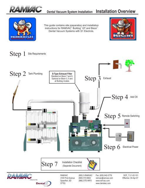
Dental <strong>Vacuum</strong> System Installation<br />
Installation Overview<br />
This guide contains site preparation and installation<br />
instructions for RAMVAC ® Bulldog ® QT and Bison ®<br />
Dental <strong>Vacuum</strong> Systems with S1 Electrols.<br />
Step 1<br />
Site Requirements<br />
Step 2<br />
Tank Plumbing<br />
Step<br />
S-Type Exhaust Filter<br />
Standard on Bison 7 and 9.<br />
Optional on Bison 3, 5 and<br />
all Bulldog models.<br />
3 Exhaust Step 4<br />
Add OIl<br />
Step 5<br />
Remote Switching<br />
Step 6<br />
Electrical Power<br />
Step 7<br />
Installation Checklist<br />
(Separate Document)<br />
A Brand of the<br />
RAMVAC<br />
3100 First Avenue<br />
Spearfish, SD<br />
57783<br />
(800) 5-RAMVAC<br />
(800) 572-6822<br />
(866) DTE-INFO<br />
Fax: (605) 642-3776<br />
ramvac@ramvac.com<br />
www.ramvac.com<br />
www.dentalez.com<br />
SOF_7.5.1-02-101<br />
Effective: 30-Apr-07
Dental <strong>Vacuum</strong> System Installation<br />
Page 2<br />
SOF_7.5.1-02-101<br />
Effective date: 30-Apr-07
Dental <strong>Vacuum</strong> System Installation<br />
Table of Contents<br />
Step 1 Bulldog Site Requirements 4<br />
Step 1 Bison Site Requirements 5<br />
Step 2 Tank Plumbing 6<br />
Step 3 Exhaust Plumbing 7<br />
Step 4 Remote Switching Options 8<br />
Step 5 Electrical Power 9<br />
Step 6 Three Phase Startup 10<br />
Step 7 Installation Checklist 11<br />
SOF_7.5.1-02-101<br />
Effective date: 30-Apr-07<br />
Page 3
Bulldog ®<br />
QT<br />
Site Requirements<br />
Comply with Local and National<br />
Electrical and Plumbing Codes.<br />
Follow NFPA 99c Edition, Level 3<br />
<strong>Vacuum</strong> System Recommendations.<br />
Ambient Temperature<br />
32° to 104° F<br />
(0° to 40° C)<br />
Protect from Water.<br />
Controls are NOT waterproof.<br />
Motors are NOT Waterproof.<br />
Humidity 0% to 95%<br />
No Condensing Moisture<br />
Common Installations Shown<br />
Contact RAMVAC for more options<br />
Bulldog - 15 Gallon Otter Tank <br />
stacked<br />
Bulldog - 15 Gallon Otter Tank<br />
suspended<br />
Bulldog -15-Gallon Otter Tank<br />
side by side<br />
Product Dimensions 15-Gallon Otter Tank Bulldog QT 1 & 2 Bulldog-15 Gallon Otter Tank Stacked<br />
Nominal Width 25” (640 mm) 21” (520 mm) 25” (640 mm)<br />
Nominal Depth 19” (490 mm) 17” (430 mm) 19” (490 mm)<br />
Nominal Height 24” (610 mm) 25” (640 mm) 44” (1120 mm)<br />
Nominal Height<br />
with S-Type Exhaust Filter<br />
N/A<br />
48” (1220 mm)<br />
67” (1700mm)<br />
Drain valve centerline to floor 8” (203 mm) N/A 8” (203 mm)<br />
Add 6” (155 mm) to each dimension for working space<br />
Page 4<br />
SOF_7.5.1-02-101<br />
Effective date: 30-Apr-07
Bison ®<br />
Site Requirements<br />
Comply with Local and National<br />
Electrical and Plumbing Codes.<br />
Follow NFPA 99c Edition, Level 3<br />
<strong>Vacuum</strong> System Recommendations.<br />
Ambient Temperature<br />
32° to 104° F<br />
(0° to 40° C)<br />
Protect from Water.<br />
Controls are NOT Waterproof.<br />
Motors are NOT Waterproof.<br />
Humidity 0% to 95%<br />
No Condensing Moisture<br />
Common Installations Shown<br />
Contact RAMVAC for more options<br />
S-Type Exhaust Filter *<br />
Standard on Bison 7 and 9.<br />
Optional on Bison 3, 5, and<br />
all Bulldog models.<br />
Bison - 50 Gallon Tank<br />
side by side<br />
Bison - 30 gallon Otter Tank<br />
side by side<br />
Bison - 30-Gallon Otter Tank<br />
stacked using Bison Platform<br />
Product Dimensions 30-Gallon Otter Tank Bison 3 & 5 Bison - 30 gallon Otter Tank Stacked Bison 7 & 9 50-Gallon Cylindrical Tank<br />
Nominal Width 29” (740 mm) 26” (660 mm) 32” (820 mm) 26” (660 mm) 22” (560mm)<br />
Nominal Depth 21” (540 mm) 19” (490 mm) 21” (540 mm) 22” (560 mm) 22” (560mm)<br />
Nominal Height 36” (920 mm) 30” (760 mm) 70” (1780 mm) 30” (765 mm) 62” (1580mm)<br />
Drain valve centerline to floor 8” (203 mm) N/A 8” (203 mm) N/A 5” (130mm)<br />
* For S-type Exhaust Filters add 26 inches to height of Power Unit.<br />
Add 6” (155 mm) to each dimension for working space.<br />
SOF_7.5.1-02-101<br />
Effective date: 30-Apr-07<br />
Page 5
Tank Plumbing<br />
Facility <strong>Vacuum</strong> Lines<br />
• Build Like a Drain Line:<br />
- Use DWV Fittings<br />
- Minimum slope !” per 10 ft (2 mm per 1m)<br />
• Up to 5 rooms: 1-1/2” (or larger) PVC Schedule 40 or equivalent<br />
• 5 to 15 rooms: 2” PVC (or larger) Schedule 40 or equivalent<br />
• If an inline low spot is unavoidable, place it in a known<br />
location and incorporate a clean-out.<br />
• For overhead piping, contact RAMVAC<br />
• For nitrous oxide scavenging, contact RAMVAC<br />
• Follow NFPA 99c Edition, RAMVAC Instructions, and local codes.<br />
Tank to <strong>Vacuum</strong> Power Unit<br />
Bulldog® - 1 1/2” PVC Schedule 40 with<br />
DWV fittings or equivalent.<br />
Bison® - 2” PVC Schedule 40 with<br />
DWV fittings or equivalent.<br />
Use new, clean pipe to connect tank<br />
to <strong>Vacuum</strong> Power Unit.<br />
Do NOT reuse old or exsisting pipe.<br />
Vent<br />
Trap<br />
Vent<br />
Drain Branch<br />
To Sewer<br />
Trap<br />
Drain Line Options<br />
NFPA 99c Edition<br />
Slide Valve<br />
Drain Check Valve<br />
Waste Pipe<br />
Bulldog or Bison<br />
(Bison Shown)<br />
To Sewer<br />
Vent<br />
Drain Branch<br />
Trap<br />
Trap<br />
Vent<br />
Multiple Tank Setup Guide is packed with Tanks<br />
Tank Drain Line<br />
• Waste Pipe, Slide Valve, and Drain Check Valve<br />
- 1-1/2” PVC Schedule 40 with DWV fittings.<br />
- Min. slope !” per 10 ft (2 mm per 1m).<br />
- Use only RAMVAC supplied 1 1/2” drain check valve.<br />
• Trap and Drain Branch<br />
- Trap and branch line 2 sizes larger than waste pipe.<br />
- Trap seal minimum 4” deep.<br />
• Vents<br />
- Trap vent size no less than half the trap and drain branch<br />
size.<br />
- Vents no smaller than drain check valve.<br />
- Vents must extend minimum of 6” above tank top before<br />
turning horizontal.<br />
• Follow NFPA 99c Edition, RAMVAC Instructions, and local<br />
codes.<br />
Page 6<br />
SOF_7.5.1-02-101<br />
Effective date: 30-Apr-07
Exhaust Plumbing<br />
BIOHAZARD<br />
Breathing Dental <strong>Vacuum</strong> System Exhaust May Be Harmful.<br />
Exhaust to Outside of Building.<br />
Follow NFPA 99c, RAMVAC Instructions, and local requirements.<br />
Minimum Exhaust Length = 15 feet<br />
from RAMVAC pump to outside end.<br />
Contact RAMVAC for shorter distances.<br />
Outside End<br />
(Installer supplied)<br />
Turn outside end down toward ground and screen to prevent entry of water, debris, and creatures.<br />
Locate inconspicuously for sight and sound. Locate to prevent exhaust from entering building.<br />
Outside Wall<br />
Roof Line<br />
Run Dedicated Exhaust Lines for each RAMVAC unit installed:<br />
DO NOT connect to plumbing vents.<br />
Size: 2”<br />
Type:<br />
Bulldog QT - PVC Sch 40, Sch 80, CPVC, or metal (NOT tar coated).<br />
Bulldog QT with vacuum set stronger than 9” Hg, use Bison type.<br />
Bison® - Sch 80, CPVC, or metal (NOT tar coated).<br />
(Option: PVC Sch 40 or equivalent after first 10 feet of run).<br />
Support Loosely:<br />
DO NOT allow piping to touch ductwork.<br />
DO NOT make solid attachment to building structure.<br />
Seal:<br />
Slope:<br />
All joints must be oil tight.<br />
All horizontal lines toward the vacuum unit, a standard plumbing slope.<br />
Rubber Roofs: Terminating an exhaust run over a rubber roof is not a recommended practice.<br />
If exhaust termination above a rubber roof is necessary, protect the roof from contact with the<br />
exhaust oil vapor or droplets.<br />
1. Terminate exhaust pipe a sufficient distance from rubber roof, or<br />
2. Cover the rubber roof surface with material not sensitive to oil, and<br />
3. Install a RAMVAC S-Type Exhaust filter.<br />
SOF_7.5.1-02-101<br />
Effective date: 30-Apr-07<br />
Page 7
Remote Switching Options<br />
OPTION 1 (RECOMMENDED): Switch (low voltage) Remote Control Circuit F, G, H as shown below.<br />
RAMVAC<br />
Remote Control<br />
Panel or<br />
equivelent with<br />
illuminated<br />
12V Switch<br />
1.<br />
2.<br />
3.<br />
F.<br />
G.<br />
H.<br />
S1 Electrols<br />
Terminals<br />
Toggle Switch<br />
or other<br />
non-illuminated<br />
switch<br />
(option)<br />
F.<br />
H.<br />
S1 Electrols<br />
Terminals<br />
Switch<br />
Light<br />
Common<br />
F.<br />
G.<br />
H.<br />
Vac Switch<br />
Vac Light<br />
Common<br />
Illuminated Remote Switch<br />
F - +5v DC<br />
G - +12v DC<br />
H - 5v & 12v DC Ground<br />
S1 Electrols Terminals<br />
Maximum wire lengths<br />
18 gauge - 500 feet<br />
OPTION 2: Use Run / Stop button on S1 Electrols if remote switch is not used.<br />
Caution: This option may put Electrols into bypass mode.<br />
OPTION 3 (USE WITH CAUTION): When switching the ( high voltage) power circuit, observe the following precautions:<br />
• Major Safety Hazard and Code Violation, if neutral of 115v power or just one leg of 220v power is switched.<br />
• Some S1 functions are lost.<br />
• System will not always respond as described in User Guide.<br />
• Contact RAMVAC for instructions if you elect to remotely switch a (high voltage) power circuit.<br />
Page 8<br />
SOF_7.5.1-02-101<br />
Effective date: 30-Apr-07
Electrical Power<br />
MODEL<br />
Hp (kw) Phase "<br />
Bulldog® QT 1, 2 1.0 (0.7) 1<br />
Bison® 3, 5, 7 3.0 (2.2)<br />
Bison 9 5.0 (3.7) 3<br />
1<br />
3<br />
MOTOR " THHN WIRE SIZE # PROTECTION # , $ , %<br />
Voltage "<br />
(min - max)<br />
115<br />
(104-127)<br />
230<br />
(208-253)<br />
230<br />
(208 -253)<br />
230<br />
(208 -253)<br />
460<br />
(414 - 506)<br />
230<br />
(208 -253)<br />
460<br />
(414 - 506)<br />
Max Amps 50 ft. 100 ft. Breaker # Fusetron # , $<br />
13.4 @ 115V 12 ga. 10 ga. 20 amp FRN 25<br />
6.7 @ 230V 12 ga. 12 ga. 15 amp FRN 8<br />
16.0 @ 230V 10 ga. 10 ga. 20 amp FRN 25<br />
8.3 @ 230V 12 ga. 12 ga. 15 amp FRN 12<br />
4.2 @ 460V 12 ga. 12 ga. 15 amp FRN 5<br />
14.0 @ 230V 12 ga. 12 ga. 20 amp FRN 25<br />
7.0 @ 460V 12 ga. 12 ga. 15 amp FRN 10<br />
FOOTNOTES:<br />
1. Motors are standard 230v, 1 phase, 60 Hz, except Bison 9 motors are 230v, 3 phase 60 Hz.<br />
Other models are available for other voltages, phase, and 50 Hz power.<br />
2. Recommendation only. Ensure compliance with National and Local codes.<br />
3. Fuses must have time delays or be otherwise suitable for motor circuit.<br />
4. Disconnect must be fusible and sized per UL 98, UL 489, or UL 508.<br />
Must be supplied and installed by a licensed electrician.<br />
Single Phase Installation<br />
For three phase power, see “Three Phase Startup”.<br />
RAMVAC Supplied Equipment<br />
Owner / Contractor Supplied Equipment<br />
Disconnect %<br />
Power Panel<br />
(dedicated breakers)<br />
6 ft. conduit and wires<br />
(connects to Disconnect)<br />
Bulldog or Bison<br />
(Bulldog shown)<br />
SOF_7.5.1-02-101<br />
Effective date: 30-Apr-07<br />
Page 9
Three Phase Startup<br />
Three Phase <strong>Vacuum</strong> Power Unit Startup<br />
To verify proper pump rotation, use this procedure when starting a three phase vacuum unit for the first time.<br />
CAUTION: Continuous improper rotation can permanently damage pump.<br />
1. Lift <strong>Vacuum</strong> Controller up and out of Filtrols. (See Illustration)<br />
2. Remove Main Air Filter from inside Filtrols. (See Illustration)<br />
3. Check for correct rotation:<br />
a. Place hand in Filtrols close to pump inlet pipe.<br />
b. Run Power Unit just long enough to feel if inlet pipe<br />
is blowing or sucking air; then turn the Power Unit off.<br />
4. If air blows out of inlet pipe:<br />
a. Reverse any two motor leads on starter. (See bottom right illustration).<br />
b. Repeat step 3.<br />
5. If air sucks into inlet pipe:<br />
a. Clean any oil or debris out of Filtrols.<br />
b. Reinstall Main Air Filter.<br />
c. Reinstall <strong>Vacuum</strong> Controller.<br />
<strong>Vacuum</strong> Controller<br />
Main Air Filter<br />
Filtrols<br />
Notes:<br />
Contents inside motor starters will vary.<br />
For simplicity, not all starter box wiring is shown.<br />
Starter Box<br />
3 phase and<br />
50Hz models<br />
ONLY<br />
Power Panel<br />
(dedicated breakers)<br />
Disconnect<br />
Switch any two of these wires<br />
to reverse rotation.<br />
Page 10<br />
SOF_7.5.1-02-101<br />
Effective date: 30-Apr-07
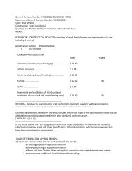
INSTALLATION CHECKLIST<br />
Dentist or<br />
Institution<br />
Name:<br />
Dental<br />
Facility<br />
Name:<br />
Print or Type<br />
Mailing Address:<br />
(City) (State) (Zip)<br />
Phone: ( ) _____ - _________ Facility person responsible<br />
Installation Date: ________________ for RAMVAC maintenance:<br />
Email:<br />
<strong>Vacuum</strong> Unit Model No.<br />
8 E. . .<br />
Tank Model No.<br />
5<br />
Complete by Installer<br />
<strong>Vacuum</strong> Unit Serial No. Tank Serial No.<br />
<strong>Vacuum</strong> Plumbing<br />
Electrical<br />
____ Number of Treatment Rooms / Chairs<br />
________ Breaker/Disconnect Amp Rating<br />
____ Number of <strong>Vacuum</strong> Sinks<br />
________ Line Voltage<br />
____ Number of <strong>Vacuum</strong> Cuspidors<br />
________ Running Voltage<br />
Piping Layout<br />
________ Amps Lead 1 (all motors)<br />
[ ] Overhead Lift Height ________ (Floor to Trunk Line) ________ Amps Lead 2 (all motors)<br />
Copy<br />
[ ] Below Grade<br />
________ Amps Lead 3 (3ph motors)<br />
[ ] Pipe Size (Trunk Line) ________<br />
Pump Lubrication<br />
[ ] Other________________________________________ [ ] Machine is installed level<br />
___<br />
[ ] Oil Level OK<br />
Tank Drain<br />
Drip Rate<br />
[ ] Air Gap<br />
________ Drips/min - Right Dripper (All systems)<br />
[ ] No Air Gap, Vented per NFPA 99c<br />
________ Drips/min - Left Dripper (All systems)<br />
Exhaust Plumbing<br />
________ Drips/min - Center Dripper (Bison 7 & 9)<br />
Y N Dedicated exhaust plumbing per unit to outside of building<br />
Y N Exhaust pipes joints sealed<br />
Switching<br />
Y N Exhaust piping loosely supported to isolate vibration<br />
What on-off switching method will be used?<br />
Y N Outside end capped or turned down to prevent entry of rain or snow [ ] Switch on S1 Electrol<br />
Y N Outside end screened to prevent entry of animals<br />
Exhaust Pipe Material<br />
[ ] PVC Sch 40<br />
[ ] PVC Sch 80<br />
[ ] Copper<br />
__<br />
[ ] Other________________________________________<br />
[ ] Remote Switch<br />
Seperate Document<br />
(Shipped with Power Unit)<br />
[ ] RAMVAC Remote Control Panel<br />
[ ] Non-Illuminated Switch<br />
[ ] Non-RAMVAC Illuminated Switch<br />
I have demonstrated and explained Operation and Maintenance procedures, using the User Guide and hardware, to the facility person<br />
responsible for RAMVAC maintenance:<br />
_______________________________________________________<br />
(Printed Name of Installer)<br />
____________________________________________________<br />
(Dealer)<br />
Free Gift Certificate for Installers! Just complete information on back of white copy.<br />
Complete by Owner<br />
Warranty Initialization<br />
• I have a User Guide and I will comply with the operation and maintenance instructions or contact RAMVAC if I cannot.<br />
• I have a completed copy of the RAMVAC Installation Checklist.<br />
• I understand that RAMVAC warranty coverage depends on RAMVAC Corporation’s receipt of this document.<br />
____________________________________________________ ____________________________________________________<br />
(Printed Name of Owner or Authorized Agent)<br />
(Signature of Owner or Authorized Agent)<br />
SOF_7.5.1-02-101<br />
Effective date: 30-Apr-07<br />
Page 11
3100 First Avenue<br />
(800) 5-RAMVAC<br />
Spearfish,SD 57783<br />
FAX (605) 642-3776<br />
www.ramvac.com<br />
© 2007 RAMVAC Dental Products All rights reserved.<br />
No part of this publication may be copied or distributed,<br />
transmitted or transcribed in any form or by any means<br />
without the expressed written permission of<br />
RAMVAC Dental Products, Spearfish, SD 57783<br />
EXCLUSIVELY FROM<br />
ISO 9001:2000 certified facility<br />
ISO 13485:2003 certified facility<br />
3100 FIRST AVENUE, SPEARFISH, SD 57783<br />
TOLL FREE: 800-5-RAMVAC (800-572-6822)<br />
PHONE: (605) 642-4614 • FAX: (605) 642-3776<br />
e-mail: ramvac@ramvac.com<br />
website: www.ramvac.com<br />
A Brand of the<br />
The Integrated Supplier<br />
PHONE: (866-DTE-INFO)<br />
www.dentalez.com<br />
SOF_7.5.1-02-101<br />
Effective date: 30-Apr-07