

Lenovo G470/G475/G570/G575 Hardware Maintenance Manual
Lenovo G470/G475/G570/G575 Hardware Maintenance Manual
Lenovo G470/G475/G570/G575 Hardware Maintenance Manual

You also want an ePaper? Increase the reach of your titles
YUMPU automatically turns print PDFs into web optimized ePapers that Google loves.
52<br />
<strong>Lenovo</strong> <strong>G470</strong>/<strong>G475</strong>/<strong>G570</strong>/<strong>G575</strong> <strong>Hardware</strong> <strong>Maintenance</strong> <strong>Manual</strong><br />
1120 Power board and touch inductive panel<br />
For access, remove these FRUs in order:<br />
• “1010 Battery pack” on page 34<br />
• “1030 Optical drive” on page 36<br />
• “1040 Hard disk drive (HDD)/Memory/CPU (Central processing unit)/Mini<br />
PCI ExpressCard slot compartment cover ” on page 37<br />
• “1050 Hard disk drive ” on page 38<br />
• “1100 Keyboard” on page 47<br />
• “1110 Keyboard bezel” on page 49<br />
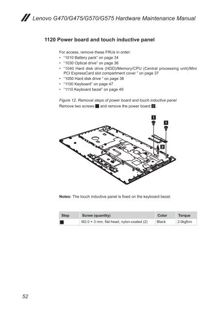
Figure 12. Removal steps of power board and touch inductive panel<br />
Remove two screws 1 and remove the power board 2.<br />
Notes: The touch inductive panel is fixed on the keyboard bezel.<br />
Step Screw (quantity) Color Torque<br />
1 M2.0 × 3 mm, flat-head, nylon-coated (2) Black 2.0kgfcm<br />
1<br />
2<br />
1