

Lenovo G470/G475/G570/G575 Hardware Maintenance Manual
Lenovo G470/G475/G570/G575 Hardware Maintenance Manual
Lenovo G470/G475/G570/G575 Hardware Maintenance Manual

Create successful ePaper yourself
Turn your PDF publications into a flip-book with our unique Google optimized e-Paper software.
66<br />
<strong>Lenovo</strong> <strong>G470</strong>/<strong>G475</strong>/<strong>G570</strong>/<strong>G575</strong> <strong>Hardware</strong> <strong>Maintenance</strong> <strong>Manual</strong><br />
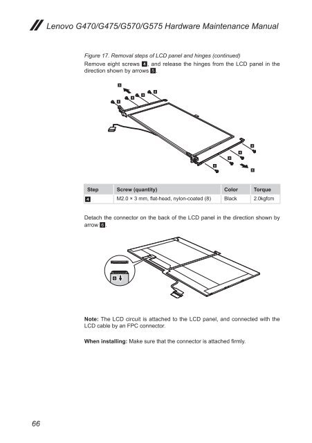
Figure 17. Removal steps of LCD panel and hinges (continued)<br />
Remove eight screws 4, and release the hinges from the LCD panel in the<br />
direction shown by arrows 5.<br />
4<br />
5<br />
4<br />
4<br />
4<br />
Step Screw (quantity) Color Torque<br />
4 M2.0 × 3 mm, flat-head, nylon-coated (8) Black 2.0kgfcm<br />
Detach the connector on the back of the LCD panel in the direction shown by<br />
arrow 6.<br />
6<br />
Note: The LCD circuit is attached to the LCD panel, and connected with the<br />
LCD cable by an FPC connector.<br />
When installing: Make sure that the connector is attached firmly.<br />
4<br />
4<br />
4<br />
4<br />
5