Create successful ePaper yourself
Turn your PDF publications into a flip-book with our unique Google optimized e-Paper software.
V E R S I O N 3 . 0<br />
<strong>Software</strong><br />
<strong>Manual</strong><br />
V E R S I O N 3 . 0
*C4400008*<br />
<strong>Crest</strong> <strong>Audio</strong> Inc.<br />
100 Eisenhower Drive<br />
Paramus NJ 07652 USA<br />
TEL 201.909.8700 FAX 201.909.8744<br />
http://www.crestaudio.com<br />
NexSys <strong>Software</strong> v. 3.0 <strong>Manual</strong><br />
v 1.0 13 August 1997<br />
© 1997
<strong>Crest</strong> <strong>Audio</strong> Inc. NexSys v. 3.0<br />
Table Of Contents<br />
1. INTRODUCTION<br />
Page<br />
1.1<br />
1.1 What is included in this manual 1.1<br />
1.2 What is not included 1.2<br />
1.3 System Requirements 1.2<br />
1.4 <strong>Manual</strong> Conventions 1.2<br />
1.5 <strong>Software</strong> Conventions 1.2<br />
Use of the Mouse Buttons 1.3<br />
1.6 <strong>Software</strong> Installation 1.3<br />
1.7 Technical Support 1.3<br />
2. OVERVIEW 2.1<br />
Devices 2.1<br />
Plans 2.1<br />
Groups 2.2<br />
Snapshots - Plan & Group 2.2<br />
Scenes 2.2<br />
Event Monitor 2.2<br />
<strong>Software</strong> Security 2.2<br />
Event Scheduler 2.2<br />
Load Monitoring 2.3<br />
<strong>Audio</strong> Return 2.3<br />
MIDI Interfaces 2.3<br />
3. NETWORK TOPOLOGY 3.1<br />
3.1 Amplifier Classes 3.1<br />
3.2 Networks, Nodes and Buses 3.1<br />
Hubs 3.3<br />
Supervisors (Pro class) 3.3<br />
Load Monitor Mainframe (Pro class) 3.4<br />
3.3 Network Terminations & Wire Type 3.5<br />
3.4 Network Addressing 3.5<br />
4. BUS SERVER INSTALLATION AND CONNECTION 4.1<br />
4.1 Installing the Bus Server Card 4.1<br />
Connecting the Bus Server to the NexSys Bus 4.1<br />
4.2 Communicating with the Bus Server 4.2<br />
Changing the Bus Server’s I/O Address 4.2<br />
5. THE TOOLBAR & MENUS 5.1<br />
5.1 Toolbar 5.1<br />
5.2 Menus 5.2<br />
5.3 Right Mouse Menus 5.2<br />
TOC 1
NexSys v. 3.0 <strong>Crest</strong> <strong>Audio</strong> Inc.<br />
6. BUILDING A PLAN 6.1<br />
6.1 Making a New Plan 6.1<br />
6.2 AutoPlan 6.1<br />
6.3 <strong>Manual</strong>ly Adding devices 6.2<br />
6.4 Saving Your Plan 6.3<br />
6.5 Plan Inventory 6.3<br />
6.6 Device Setup 6.4<br />
Changing the Device’s Name 6.4<br />
Changing the Device’s Address 6.5<br />
6.7 Venue Bitmap Background 6.6<br />
7. GROUPS 7.1<br />
7.1 Creating a group 7.1<br />
7.2 Renaming a group 7.1<br />
7.3 Deleting a group 7.1<br />
7.4 Adding devices to the group 7.1<br />
Moving a device 7.2<br />
Copying a device 7.2<br />
Selecting Multiple devices 7.2<br />
7.5 Quickly Opening a group 7.3<br />
7.6 Group Views 7.3<br />
Group List View & the Plan Inventory 7.3<br />
Group Console Views 7.4<br />
8. NEXSYS FAULTS, ALERTS & EVENTS 8.1<br />
8.1 Alert Panels 8.1<br />
8.2 Amplifier Warning Thresholds 8.2<br />
8.3 Event Monitor and the Event Log 8.2<br />
Opening the Event Monitor 8.2<br />
Event Log Setup 8.2<br />
9. CONTROLLING YOUR AMPLIFIERS 9.1<br />
9.1 Amplifier Controls 9.1<br />
Amplifier Level Control 9.1<br />
Amplifier Mute Control 9.1<br />
Amplifier Solo Control 9.2<br />
Amplifier Polarity 9.2<br />
<strong>Audio</strong> Return 9.2<br />
VU Meters 9.2<br />
9.2 Related devices 9.3<br />
9.3 Group & Plan Amplifier Control Panel 9.3<br />
Group/Plan Level 9.3<br />
Group/Plan Mute 9.3<br />
9.4 Control Hierarchy 9.4<br />
9.5 Solo Safety 9.5<br />
TOC 2
<strong>Crest</strong> <strong>Audio</strong> Inc. NexSys v. 3.0<br />
10. SNAPSHOTS 10.1<br />
10.1 Inserting a New Snapshot 10.1<br />
10.2 Recalling a Snapshot 10.1<br />
10.3 Updating a Snapshot 10.2<br />
10.4 Editing a Snapshot 10.2<br />
10.5 Executing a Snapshot on Startup 10.3<br />
10.6 Recalling Snapshots from Outside of NexSys 10.3<br />
11. SCENES 11.1<br />
11.1 Scene Maintenance 11.1<br />
11.2 Recalling a Scene 11.1<br />
12. SECURITY 12.1<br />
12.1 Access Levels 12.1<br />
12.2 Security Setup 12.1<br />
12.3 Login / Logout 12.2<br />
13. EVENT SCHEDULER 13.1<br />
13.1 Event Setup and Operations 13.1<br />
13.2 Report Modes 13.2<br />
13.3 Example Application 13.2<br />
13.4 MIDI HEX Programming 13.3<br />
14. MIDI INTERFACE 14.1<br />
14.1 Creating a MIDI Device within NexSys 14.1<br />
14.2 Recalling MIDI Patches 14.1<br />
15. LOAD MONITORING 15.1<br />
15.1 Load Monitor Setup for CK family Amplifiers 15.1<br />
15.2 Load Monitor Setup for Pro Class Amplifiers 15.1<br />
15.3 The Reference Curve 15.1<br />
16. CK FAMILY SEQUENTIAL TURN-ON/TURN-OFF (STO) 16.1<br />
17. CK FAMILY INPUT MODULES & CONTROL PANELS 17.1<br />
Appendix A - DECIMAL TO HEXADECIMAL CONVERSION TABLE<br />
Appendix B - MENU REFERENCE<br />
Appendix C - BUS SERVER DIP SWITCH SETTINGS<br />
TOC 3
NexSys v. 3.0 <strong>Crest</strong> <strong>Audio</strong> Inc.<br />
Screen Captures and Drawings<br />
Item Page<br />
Plan Inventory Window 2.1, 6.3<br />
NexSys Network with CK family amplifiers and hubs 3.2<br />
Pro class network setup diagram 3.4<br />
Amplifier Channel Setup Windows 3.5<br />
Bus Server Card rotary switch locations 4.1<br />
Bus Server Dialog Window 4.2<br />
Toolbar 5.1<br />
NexSys Menu Hierarchy 5.2, 5.3<br />
Plan Name Window 6.1<br />
NexSys Autoplan Window 6.2<br />
Plan Inventory Toolbar Buttons 6.2<br />
Device Setup Menu 6.4<br />
CK family Amplifier Setup Window 6.5<br />
Pro Class Amplifier Setup Window 6.5<br />
MIDI Device Setup Window 6.6<br />
Venue Bitmap Background Example 6.6<br />
New Group Dialog Box 7.1<br />
Group Selection Tool 7.3<br />
Group List View 7.3<br />
Group Console Views 7.4<br />
Balloon Help example 7.5<br />
Alert Panels and icons 8.1<br />
Amplifier Warning Control Window 8.2<br />
Single amplifier control panels 9.1<br />
Amplifier Mute Control Button 9.1<br />
Amplifier Solo Control Button 9.2<br />
Amplifier Polarity Control Button 9.2<br />
<strong>Audio</strong> Return Control Button 9.2<br />
VU Meters 9.2<br />
Related Devices Menu 9.3<br />
Group and Plan Amplifier Control Panel 9.3<br />
Group and Plan Level Control Panel 9.3<br />
Control Hierarchy Examples 9.4<br />
Control Hierarchy Diagram 9.5<br />
Solo Safety Toggle 9.5<br />
Insert Snapshot Dialog Box 10.1<br />
Snapshot Window 10.2<br />
Edit Snapshot Window 10.2, 10.3<br />
Scene Maintenance Window 11.1<br />
Security Administrator Dialog Window 12.2<br />
NexSys Login Window 12.2<br />
Define Event Window 13.1<br />
MIDI Device Setup Window 14.1<br />
MIDI Patch Control Window 14.1<br />
Load Monitor Window 15.3<br />
Plan Inventory (Sequential Turn-On) window 16.1<br />
CK family Input Module Control Panels 17.1<br />
Bus Server End View Appendix C<br />
TOC 4
<strong>Crest</strong> <strong>Audio</strong> Inc. NexSys v. 3.0<br />
1. Introduction<br />
Thank you for purchasing NexSys - the powerful computer controlled audio system for your<br />
<strong>Crest</strong> <strong>Audio</strong> power amplifiers. With its practical and intuitive graphical interface, NexSys<br />
has won praise from audio engineers in every discipline. After familiarizing yourself with<br />
NexSys, you will realize the value and flexibility that this software package offers.<br />
1.1 What is included in this manual<br />
The NexSys <strong>Software</strong> <strong>Manual</strong> is organized into several sections that will provide users with<br />
the information necessary to set up and run a NexSys system.<br />
Chapter 2 Overview. Presents an introduction to NexSys concepts and a guide<br />
to each software section.<br />
Chapters 3 & 4 Network Topology and Bus Server Installation & Connection.<br />
Presents essential data on your NexSys system components and<br />
their interface to the computer and the NexSys RS485 bus.<br />
Chapter 5 Toolbar & Menus. Offers quick access to more frequently used<br />
NexSys functions.<br />
Chapter 6 Building a Plan. Details how to build a plan from user-defined<br />
devices, groups, Snapshots, Scenes, and settings.<br />
Chapter 7 Groups. Details how to facilitate the control of amplifiers and other<br />
devices with NexSys groups.<br />
Chapter 8 NexSys Faults, Alerts & Events. Covers the various faults, or alerts,<br />
that are reported on screen and to the Event Monitor/Log.<br />
Chapter 9 Controlling Your Amplifiers. Details the many ways in which amplifiers<br />
may be controlled using NexSys.<br />
Chapter 10 Snapshots. Records Plan & Group Snapshots.<br />
Chapter 11 Scenes. How to create these graphical “desk top” arrangements,<br />
which are collections of NexSys windows that can be opened for<br />
viewing or control.<br />
Chapter 12 Security. Details how to determine which controls are included in<br />
scenes and limit access to those scenes via password protection<br />
Chapter 13 Event Scheduler. Profiles one of the most powerful and useful tools<br />
in the NexSys system. Event Scheduler allows the system operator<br />
to automate all functions that can be executed by a user.<br />
Chapter 14 MIDI Interface. Details how NexSys and the Event Scheduler can<br />
interact with MIDI equipment via the NexSys MIDI Interface.<br />
Chapter 15 Load Monitoring. Profiles this powerful diagnostic tool that provides<br />
a consistent means to verify performance of the drive lines<br />
and speakers in the system.<br />
Chapter 16 CK family Sequential Turn-On/Turn-Off (STO). Details how to<br />
sequentially turn on and turn off these amplifiers with a delay<br />
between each one.<br />
<strong>Software</strong> <strong>Manual</strong> Page 1.1
NexSys v. 3.0 <strong>Crest</strong> <strong>Audio</strong> Inc.<br />
Chapter 17 CK family Input Modules & Control Panels. Covers signal processing<br />
controls for NC modules.<br />
Appendix A Menu Reference. A complete NexSys menu reference list.<br />
Appendix B Decimal to Hexadecimal Conversion Table.<br />
Appendix C Bus Server Dip Switch Setting Reference Table.<br />
1.2 What is not included in this manual<br />
A detailed explanation of the system hardware and wiring requirements is not included in<br />
this manual, but can be found in the accompanying NexSys System Hardware <strong>Manual</strong>. A<br />
brief resume of hardware addressing and configuration is included in this document in<br />
Section 3, Network Topology. Additionally, specific information regarding amplifiers,<br />
processor modules, and related peripheral devices can all be found in the various technical<br />
data sheets or accompanying operator's manuals.<br />
1.3 System Requirements<br />
We recommend the following minimum computer configuration for NexSys 3.0 systems<br />
• Intel Pentium or compatible computer<br />
• Microsoft Windows 95<br />
• 16 megabytes of RAM<br />
• 10 megabytes of available hard disk space<br />
• Video monitor and driver card capable of displaying a resolution of 1024x768<br />
• Mouse<br />
• High density 3 1/2" (1.44 MB) floppy drive<br />
• Suggested Option- Add a modem with a third party remote control software<br />
program such as PCAnywhere or Carbon Copy if you want to control the<br />
system from a remote location.<br />
1.4 <strong>Manual</strong> Conventions<br />
Menu choices appear in the following manner throughout this manual: Plan | Save As...<br />
Holding the ALT key down and pressing the underlined key will invoke that menu choice.<br />
For example, ALT + P will drop down the Plan menu. This example also shows that there<br />
is a sub-menu or sub-selection for the Plan menu. In this case it is the Save As menu.<br />
Whenever this “information” icon is used,<br />
you will find useful operating hints in italics.<br />
1.5 <strong>Software</strong> Conventions<br />
NexSys software version 3.0 runs under Microsoft Windows 95 . This manual is written for<br />
those who have a working knowledge of Microsoft Windows. For further operating system<br />
information, please refer to your Microsoft Windows documentation. (Please note that all<br />
graphics used in this manual show NexSys operating under Windows 95.)<br />
When running the NexSys program for the first time, the main window will appear with several<br />
pull down menus, a tool bar with controls and display icons. Clicking on a pull down<br />
menu item with the left mouse button will bring out the sub-menu items under that partic-<br />
Page 1.2 <strong>Software</strong> <strong>Manual</strong>
<strong>Crest</strong> <strong>Audio</strong> Inc. NexSys v. 3.0<br />
ular function. Valid menu selections are displayed in black while those that are not are<br />
grayed out.<br />
When the cursor is placed over an icon on the tool bar, a description of its function is displayed<br />
in the border at the very bottom of the NexSys window.<br />
The term active window is used throughout this User’s Guide. An active window is the window<br />
in which you are currently working. It is the one with the highlighted title bar. Some<br />
menu items and toolbar buttons will only be enabled when the correct type of window is the<br />
active window.<br />
Use of the Mouse Buttons<br />
Menu selections are made by clicking the menu item with the left mouse button.<br />
Several additional NexSys features are accessed by use of the right mouse button,<br />
termed a ‘right click’. Whenever this icon is used it indicates the presence of<br />
a right-click feature. Right clicking will often show a pop-up menu that is related<br />
to the selected object.<br />
1.6 <strong>Software</strong> Installation<br />
The NexSys software is supplied on standard high density 3.5" floppy disks. To install<br />
NexSys, insert the #1application floppy into the drive and select SETUP.EXE. The setup<br />
program will prompt you for the location on your hard disk where the files will reside. The<br />
default directory offered by the setup program is C:\NEXSYS. If you want to install to a<br />
drive or directory other than the default you must type in the target location when prompted.<br />
Once the setup program starts it will expand the compressed files on the floppy disk and<br />
copy them to the target directory.<br />
It is recommended that you back up the directory after you have loaded the software and<br />
configured the system.<br />
A complete listing of NexSys files and their locations on the hard disk may be found in the<br />
appendix XXX.<br />
1.7 Technical Support<br />
The following contact information will be helpful in obtaining technical service support<br />
from <strong>Crest</strong> <strong>Audio</strong> for NexSys systems:<br />
<strong>Crest</strong> <strong>Audio</strong> Inc.<br />
100 Eisenhower Drive,<br />
Paramus, New Jersey 07652 USA<br />
TEL: (201) 909-8700<br />
FAX: (201) 909-8744<br />
http://www.crestaudio.com<br />
<strong>Software</strong> <strong>Manual</strong> Page 1.3
<strong>Crest</strong> <strong>Audio</strong> Inc. NexSys v. 3.0<br />
2. Overview<br />
Devices<br />
A ‘device’, as referred to in this manual, is a remote NexSys-compatible piece of electronic<br />
hardware that is capable of being controlled and/or of reporting its state. The most common<br />
devices connected to the NexSys interface are amplifiers. Other devices that may have<br />
an interface with NexSys may include Power Processor NC- input signal processors, NC-<br />
Load Monitor and NC- Sequential Power controllers.<br />
A NexSys device has two elements, its name and its network address. The name is an alphanumeric<br />
string that you give a device that has some meaning for you. By default, NexSys<br />
names devices using simple names and model numbers. You will probably want to rename<br />
devices to give cues as to their functions and locations in your system (e.g. Tower 3<br />
Subwoofer.) There is a 40 character limit on device names, although some views will not<br />
display all 40 characters.<br />
The second device element is its address. The address is a combination of the device’s network<br />
address and channel number (if applicable.) For instance, if a CKS400 amplifier is at<br />
network address 8 it would appear as two NexSys devices; one for each channel.<br />
Devices are created by choosing Device | New or by using AutoPlan. Once created they<br />
will appear within the Plan Inventory window where they are categorized by device type.<br />
Plans<br />
A Plan is to NexSys what a document file is to your word processor. The Plan contains all<br />
the information that is unique to the system. It is made up of user-defined devices, groups,<br />
snapshots, scenes, and program-defined elements such as the Plan Inventory and Event<br />
Monitor. A Plan is saved as a subdirectory of your main NexSys directory (default<br />
C:\NEXSYS) and is made up of multiple files. Only one Plan can be loaded and used by<br />
NexSys at a time.<br />
The Plan Inventory is the total collection of all devices that have been added to this plan.<br />
The plan inventory serves as a good repository from which to copy devices when creating<br />
logically-organized groups.<br />
Double-click on any device<br />
to open its control panel.<br />
Right-click on any device to<br />
pop-up a menu for device<br />
setup or to open control<br />
panels related to the<br />
selected device.<br />
Plan Inventory Window<br />
Double-click here to display<br />
the planwide amplifier<br />
control panel.<br />
Double-click here to display<br />
the planwide sequential<br />
turn-on control panel.<br />
<strong>Software</strong> <strong>Manual</strong> Page 2.1
NexSys v. 3.0 <strong>Crest</strong> <strong>Audio</strong> Inc.<br />
Groups<br />
A group is a collection of devices placed together for the purpose of common control or<br />
monitoring. You can create a group by selecting Group | New from the menu. Any device<br />
that can be controlled by NexSys can be added to a group. A single device may be added to<br />
more than one group.<br />
Groups exist to customize a Plan according to your specific needs. They serve as a tool to<br />
logically organize your Plan. For example, you may create a group that contains all amplifier<br />
channels for the low frequency drivers. You may also have a group for the stage left.<br />
There is no practical limit to the number of groups you can create.<br />
All of the amplifiers within a group may be controlled by the group control panel. Different<br />
group views provide console-like control arrangements for the channels in a group.<br />
Snapshots - Plan & Group<br />
Snapshots are a way to save NexSys control settings for later recall. A device’s current setting,<br />
such as gain, is “snapshotted” and saved under a user-defined name for instant recall<br />
at a later time. Snapshots cover two levels, Plan and group. You can open the snapshot windows<br />
by selecting Plan | Snapshot | Open or Group | Snapshot | Open.<br />
Scenes<br />
A scene is a way of saving/recalling different desktops (arrangements of windows) within<br />
NexSys. One scene may contain the amplifier control windows for the lower level of a stadium<br />
while the controls for the upper level could be saved in a different scene. Another may<br />
just contain the snapshot window as a means for simply controlling a complex sound system.<br />
Scenes can be saved via the scene maintenance window. This window is accessed by<br />
the Scene button on the tool bar or from the DeskTop | Scene menu.<br />
Event Monitor<br />
The Event Monitor tracks system wide faults and activity and generates the Event Log. An<br />
Event Log shows the “what and when” of events which occur while NexSys is running. The<br />
Event Monitor can be viewed by selecting Options | Event Monitor. The Event Log can<br />
also be saved to a file on the host computers hard disk. Once the Event Log is activated, all<br />
critical system operation information, including date and time of the event is recorded to a<br />
text file. You may give the Event Log a unique name to keep its data separate from other<br />
logs.<br />
<strong>Software</strong> Security<br />
The security features of the NexSys program allow three levels of security access with varying<br />
privileges for each level. This feature allows the system administrator to tailor who will<br />
have access to various control functions within the software. The Security Administrator<br />
window can be opened by selecting Options | Security from the menu.<br />
Event Scheduler<br />
The Event Scheduler is a second software application supplied as a companion program to<br />
NexSys. Event Scheduler allows almost limitless automated control of all NexSys functions.<br />
You can open or switch to the Event Scheduler by selecting Plan | Event Scheduler<br />
from the menu. When NexSys and the Event Scheduler appear as the top two items in the<br />
task list, you can switch between these two programs by pressing ALT + TAB.<br />
Page 2.2 <strong>Software</strong> <strong>Manual</strong>
<strong>Crest</strong> <strong>Audio</strong> Inc. NexSys v. 3.0<br />
You can program the Event Scheduler to initiate tasks at a given time (computer clock) or<br />
when some other event (such as a switch closure or a fault) takes place. A scheduled event<br />
consists of four parameters:<br />
• the event trigger<br />
• the task or action to take place, i.e. what to do<br />
• the target of the action, i.e. which device or devices to perform the action to<br />
• number of times to repeat action & at what frequency (just once, hourly, daily...)<br />
Load Monitoring<br />
Systems configured with optional Load Monitoring hardware allows NexSys to perform<br />
diagnostic impedance versus frequency testing of the load on each amplifier channel.<br />
<strong>Audio</strong> Return<br />
In systems where Load Monitoring hardware is installed, NexSys provides a line level<br />
<strong>Audio</strong> Return port so that program material may be bussed to the remote control position<br />
for audible monitoring.<br />
MIDI Interfaces<br />
MIDI-compliant third party devices (such as EQ’s, delays, etc.) may be controlled from<br />
within NexSys via the optional MIDI Interface unit. NexSys can send (and receive) MIDI<br />
patch changes from its control panel or as part of a snapshot.<br />
<strong>Software</strong> <strong>Manual</strong> Page 2.3
<strong>Crest</strong> <strong>Audio</strong> Inc. NexSys v. 3.0<br />
3. Network Topology<br />
3.1 Amplifier Classes<br />
NexSys hardware is broken into two general groups: components for the CKS, CKV and<br />
CKX Series amplifiers or the “CK family amplifiers” and Professional, FCV, CC & CV<br />
Series amplifiers or the “Pro class amplifiers”.<br />
CK family amplifiers utilize a unique modular approach whereby both NexSys network and<br />
Load Monitoring modules are installed in the amplifier itself. In addition, a variety of input<br />
signal (analog and digital) processing modules are available to expand NexSys as a signal<br />
processing system.<br />
Pro class amplifiers are connected to the bus via a Supervisor main frame and daughter<br />
cards; Load Monitoring also takes place via an outboard main frame and daughter card unit.<br />
NexSys controllable signal processing modules are not available with this class.<br />
3.2 Networks, Nodes and Buses<br />
The NexSys network is EIA485 compliant. Each Device on the network is termed a node.<br />
Nodes on a NexSys network include: NC-NXS modules installed in CKS, CKV and CKX<br />
amplifiers, Hubs (NDP-JTH), MIDI Interfaces, Supervisor and Load Monitor Mainframes<br />
(for Professional, CC/CV & FCV Series amplifiers), and the Bus Server itself.<br />
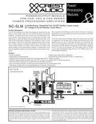
As with any network, each node must have a unique address. Valid addresses range from 1<br />
to 111, inclusive. In the figure on the next page, an address for each node is shown outside<br />
and next to the Device. For instance, the CKS 800 amplifier is at address 0,3.<br />
<strong>Software</strong> <strong>Manual</strong> Page 3.1
NexSys v. 3.0 <strong>Crest</strong> <strong>Audio</strong> Inc.<br />
Termination All bus wiring is twisted pair<br />
Primary Bus<br />
1<br />
2<br />
3<br />
10<br />
20<br />
Up to 32 devices<br />
Termination<br />
On<br />
On<br />
Off<br />
Remote<br />
On<br />
Off<br />
Off<br />
Remote<br />
On<br />
Off<br />
Remote<br />
On<br />
Off<br />
Remote<br />
On Active<br />
Off<br />
On Active<br />
Off<br />
Remote<br />
Bus Server (in PC)<br />
Protect AC<br />
ACL<br />
Ch A Ch B<br />
Active Signal Signal<br />
Protect ACL<br />
ACL<br />
Ch A Ch B<br />
Active Signal Signal<br />
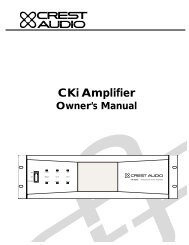
A NexSys Network with CK family amplifiers and hubs<br />
ACL<br />
Signal<br />
ACL<br />
Signal<br />
Protect AC<br />
ACL<br />
Ch A Ch B<br />
Active Signal Signal<br />
Protect ACL<br />
ACL<br />
Ch A Ch B<br />
Active Signal Signal<br />
NDP-JTH<br />
CKS 200<br />
Professional Power Amplifier<br />
CKS 400<br />
Professional Power Amplifier<br />
CKS 800<br />
Professional Power Amplifier<br />
NexSys HUB<br />
Secondary Bus<br />
4 5<br />
CKV 200<br />
Professional Power Amplifier<br />
1 2<br />
CKS 1600-2<br />
Professional Power Amplifier<br />
Amplifier<br />
Amplifier<br />
Amplifier<br />
NexSys Hub<br />
Termination<br />
Up to 32<br />
devices<br />
Termination<br />
Termination<br />
While a node itself can only be set with a single address, NexSys may report its address with<br />
multiple levels or tiers. This is because multiple NexSys networks may be interconnected<br />
using NexSys hubs or because data-concentrating devices (such as Supervisors) may reside<br />
on the network.<br />
Loosely defined, a bus represents a group of nodes connected together via twisted pair<br />
cable, with a terminating resistor at each end. that are not separated by a hub. The group of<br />
all busses that are interconnected via hubs is referred to as the network.<br />
On<br />
Off<br />
Remote<br />
On<br />
Off<br />
Remote<br />
Protect AC<br />
ACL<br />
Ch A Ch B<br />
Active Signal Signal<br />
Amplifier Amplifier<br />
NDP-JTH<br />
NexSys HUB<br />
NexSys Hub<br />
Secondary Bus<br />
Protect ACL<br />
ACL<br />
Ch A Ch B<br />
Active Signal Signal<br />
Amplifier Amplifier<br />
CKV 200<br />
Professional Power Amplifier<br />
Up to 32<br />
devices<br />
CKS 1600-2<br />
Professional Power Amplifier<br />
Termination<br />
Page 3.2 <strong>Software</strong> <strong>Manual</strong>
<strong>Crest</strong> <strong>Audio</strong> Inc. NexSys v. 3.0<br />
A network may be made up of one or more busses. The bus connected to the Bus Server is<br />
defined as the primary bus. All other busses in the network are referred to as secondary<br />
busses and must be attached to the primary bus through a hub or data concentrator.<br />
All nodes on the primary bus will have single-tiered addresses as follows:<br />
Device Address<br />
CKS 200 1<br />
CKS 400 2<br />
CKS 800 3<br />
Hub (1st) 10<br />
Hub (2nd) 20<br />
Hubs<br />
A network cannot support more than 32 nodes. Hubs must be used for networks larger than<br />
32 nodes or where odd physical network runs are required. A hub has two bus connections,<br />
one for the primary side and one for the secondary side. The bus on the secondary side of<br />
the Hub (its secondary network) is electrically isolated from the primary bus but is still a<br />
part of NexSys’ overall network.<br />
Hubs expand the maximum number of nodes in a system from 32 to 1024. The number of<br />
unique addresses is also expanded.<br />
Nodes on a hub’s secondary side will have a “two part” address. The first address is the<br />
hub’s primary address (i.e. the address of the hub on the primary bus.) The second address<br />
is the address of the node on the secondary bus. In the figure, the first hub (at primary<br />
address 10) has two CKV amplifiers attached to its secondary bus. Their addresses are:<br />
Device Address<br />
CKV 200 10,4<br />
CKV 400 10,5<br />
Similarly, the second hub (at primary address 20) has two CKS amplifiers attached to it:<br />
Device Address<br />
CKS 1600 20,1<br />
CKS 1200 20,2<br />
Notice that amplifiers “CKS 1600” and “CKS 1200” on the second hub’s bus have the same<br />
addresses (1 and 2) as the CKS 200 and CKS 400 on the primary bus. This is acceptable<br />
because the inclusion of a unique primary address differentiates them in the network .<br />
Supervisors (Pro class only)<br />
A Pro class network must have at least one Supervisor. Although the two classes of amplifiers<br />
may be combined on a single network, it is helpful to separate them for illustration purposes.<br />
Each amplifier has a two part address. The first being the node address of its<br />
Supervisor main frame and the second being the amplifier number or Supervisor port number.<br />
There are two Supervisor ports per Supervisor daughter card. There is a one to one connection<br />
between each Supervisor port and amplifier.<br />
<strong>Software</strong> <strong>Manual</strong> Page 3.3
NexSys v. 3.0 <strong>Crest</strong> <strong>Audio</strong> Inc.<br />
Termination All bus wiring is twisted pair<br />
Primary Bus<br />
1<br />
2<br />
3<br />
Up to 32 devices<br />
Termination<br />
1<br />
2<br />
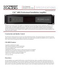
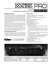
Pro class network setup diagram<br />
Load Monitor (with channel numbers)<br />
On<br />
Off<br />
Remote<br />
Bus Server (in PC)<br />
Load Monitor<br />
ACL<br />
ACL<br />
Signal Signal<br />
ACTIVE<br />
12<br />
POWER<br />
Amplifier Outputs<br />
CKS 200<br />
Professional Power Amplifier<br />
Supervisor (with port numbers)<br />
1 2<br />
Clip/Limit<br />
Signal<br />
Temp/DC<br />
Active<br />
-6<br />
-6<br />
-10 -3<br />
-10 -3<br />
-15<br />
-15<br />
-1<br />
-1<br />
-30<br />
-30<br />
-80 0dB<br />
-80 0dB<br />
Ch A<br />
Ch B<br />
Clip/Limit<br />
Signal<br />
Temp/DC<br />
Active<br />
-6<br />
-6<br />
-10 -3<br />
-10 -3<br />
-15<br />
-15<br />
-1<br />
-1<br />
-30<br />
-30<br />
-80 0dB<br />
-80 0dB<br />
Ch A<br />
Ch B<br />
The diagram above shows one Supervisor mainframe with three Professional Series amplifiers<br />
connected, one Load Monitor mainframe, and one CKS amplifier.<br />
Each Supervisor main frame can accept up to 24 dual channel amplifiers. An amplifier<br />
attached to a Supervisor uses the Supervisor’s address (primary) and its Supervisor port<br />
number to specify its secondary address. NexSys would report addresses for the Devices in<br />
this figure as follows:<br />
Device Address<br />
8001 1,1<br />
7001 1,2<br />
6001 1,24<br />
The only time a Supervisor will appear in the software is when the system is being polled<br />
during AutoPlan. NexSys does not need to identify the Supervisor as such; its presence is<br />
indicated inherently by the amplifiers attached to it -- you can't "control" or monitor a<br />
Supervisor, you can control and monitor the amplifiers.<br />
Load Monitor Mainframe (Pro Class only)<br />
The Load Monitor is similar to a Supervisor in its transparent nature to the software. You<br />
specify that an amplifier's outputs are connected to the channels of a Load Monitor in the<br />
amplifier setup dialog. The setup dialogue for the amp labeled "Pro Series 8001" would look<br />
like this for channel A:<br />
-6<br />
-10 -3<br />
Supervisor<br />
Clip/Limit<br />
Signal<br />
Temp/DC<br />
Active<br />
-6<br />
-10 -3<br />
-15<br />
-15<br />
-1<br />
-1<br />
-30<br />
-30<br />
-80 0dB -80 0dB<br />
Ch A<br />
Ch B<br />
POWER<br />
24<br />
8001 Professional Power Amplifier<br />
7001 Professional Power Amplifier<br />
6001 Professional Power Amplifier<br />
Page 3.4 <strong>Software</strong> <strong>Manual</strong>
<strong>Crest</strong> <strong>Audio</strong> Inc. NexSys v. 3.0<br />
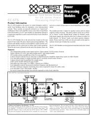
... and this set up information for channel B:<br />
Amplifier Channel Setup Windows<br />
Note that the Load Monitor must reside on the same network as the Supervisor. That is, it<br />
cannot be separated by a hub.<br />
3.3 Network Terminations & Bus Wire Type<br />
In order to minimize data reflections, the network domain must be properly terminated at<br />
extreme ends. Terminating a network is accomplished by placing a resistor (chosen to match<br />
the characteristic impedance of the cable) across the twisted pair.<br />
<strong>Crest</strong> <strong>Audio</strong> recommends using Belden 8442 unshielded twisted pair cable with 110Ω terminating<br />
resistors. Other cable may be used; however, the maximum transmission distance<br />
may decrease due to increased distributed capacitance of the cable. Use of other cable may<br />
also require different terminating resistors. Mixing different cable types on the same network<br />
or the use of star topologies within the same network must be avoided due to the<br />
impedance mismatch between cables. All cables must have a characteristic impedance of<br />
100Ω at 100kHz.<br />
All bus connections are opto-isolated, thus eliminating any ground loops and to minimize<br />
RF interference.<br />
<strong>Software</strong> <strong>Manual</strong> Page 3.5
NexSys v. 3.0 <strong>Crest</strong> <strong>Audio</strong> Inc.<br />
3.4 Network Addressing<br />
Hardware address settings are determined in two ways (depending on the amplifier class.)<br />
In Pro class amplifiers, the network address is given by its Supervisor’s address. A<br />
Supervisor is a unique network node whose address is set via DIP switches on the rear<br />
panel. This is the primary address. The rear of the Supervisor holds up to 12 daughter cards<br />
– each with 2 ports for a total of 24 ports. An amplifier’s secondary address is given by the<br />
port number to which it is connected. The maximum number of amplifiers that can be connected<br />
to a network is 744 (31 Supervisors, each with 24 amplifiers.)<br />
Pro class Load Monitor Mainframe’s network addresses are set in the same manner as<br />
Supervisors. Load Monitors can hold up to 12 daughter cards which can accommodate 2<br />
amplifier channels for a total of 24 amplifier channels.<br />
CK family Power Processing amplifiers are connected directly to the network – there is no<br />
need for Supervisors and Load Monitors. Each address is set via a hexadecimal* rotary<br />
selector on the back of the NexSys network module (NC-NXS.) A network can accommodate<br />
31 CK family amplifiers before a hub is needed. For systems with more than 31 nodes,<br />
a NexSys Hub is needed. The secondary network of the hub can accommodate 31 more<br />
nodes. So the largest CK class system would contain 961 amplifiers. Load Monitoring and<br />
other processing functions in the CK family amplifiers use the same address as the amplifier.<br />
* NexSys displays most addresses in decimal (Base 10). You must address<br />
the CK family amplifiers using the hexadecimal spinwheels. A hex-to-decimal<br />
table is provided in Appendix A.<br />
When NexSys displays or requires a number to be entered in hexadecimal<br />
(Base 16), an ‘H’ will appear next to the number. The bus server address<br />
in the options bus server window is a prime example.<br />
Page 3.6 <strong>Software</strong> <strong>Manual</strong>
<strong>Crest</strong> <strong>Audio</strong> Inc. NexSys v. 3.0<br />
4. Bus Server Installation and Connection<br />
4.1 Installing the Bus Server Card<br />
The Bus Server Card (NS-BUS-1) is an 8-bit ISA expansion card which requires installation<br />
in a vacant slot inside the NexSys host computer. If you are unsure how to insert an ISA card<br />
Device inside your computer, please consult a qualified computer technician for assistance.<br />
Otherwise, follow these instructions to ensure a safe and speedy installation.<br />
1. Make sure your computer is switched off and disconnected from the electrical<br />
mains. Be sure to use an anti-static mat or other device to reduce the risk of<br />
component failure due to static discharge.<br />
2. Open the computer case & locate a vacant ISA card slot.<br />
3. Remove the mating Phoenix connector from the Bus Server card. The card was<br />
configured and tested prior to leaving the factory. However, shipping and handling<br />
may have caused the rotary address switches to shift so verify that they<br />
are set to F (HI) and 0 (LOW).<br />
Bus Server Card rotary switch locations<br />
Carefully insert the Bus Server card into the slot ensuring that the edge connector<br />
is properly seated and that the Phoenix connector clears the computers rear<br />
panel.<br />
4. Reinstall the outer casing.<br />
5. Affix the NexSys network wire into the mating Phoenix connector and insert it<br />
into the Bus Server card. (See the section Connecting the Bus Server to the<br />
NexSys Bus, below.)<br />
6. Reconnect the AC mains<br />
Connecting the Bus Server to the NexSys Bus<br />
A 3-pin, 5mm removable terminal block (Phoenix Contact 17.5.4.46.5 or equivalent) connector<br />
is located on the back of the Bus Server card for connection to the data network. Only<br />
the positive (pin1) and negative (pin2) pins of the connector are used. The third, ground pin<br />
is normally left open. (See Appendix C for a detailed view of Bus Server connections)<br />
Network polarity must be observed when connecting the Bus Server or any other network<br />
device to a NexSys network. If reversed, the network will not operate and NexSys will not<br />
be able to communicate with any network devices.<br />
<strong>Software</strong> <strong>Manual</strong> Page 4.1
NexSys v. 3.0 <strong>Crest</strong> <strong>Audio</strong> Inc.<br />
4.2 Communicating with the Bus Server<br />
The Bus Server resides at an I/O address range in your PC. Its base address (the beginning<br />
address of the range) is referred to as the Bus Server’s I/O address, or I/O address for short.<br />
This address is set using the DIP switches positioned on the Bus Server’s mounting bracket<br />
(at the back of the PC). The default address used for Bus Server testing at the factory is<br />
380 Hex. In some instances this address may be in partial or total conflict with other cards<br />
that are installed in the host computer. For example, Ethernet network and sound cards all<br />
have I/O addresses that may use the same address (in entirety) or may partially over lap. In<br />
these instances the base I/O address must be moved to a vacant address. Some common free<br />
I/O locations and the corresponding DIP switch settings for the Bus Server card are listed<br />
in the Dip Switch Settings (Appendix C) at the end of this manual.<br />
Changing the Bus Server’s I/O Address<br />
The Bus Server’s I/O address as given by its DIP switches and its setting within the NexSys<br />
software must agree. Changing the I/O address involves the following steps.<br />
Bus Server Dialog Window<br />
1. Set the Bus Server DIP switches to the desired<br />
address.<br />
(See Appendix C for dip switch settings)<br />
2. Press the Reset button on the Bus Server mounting<br />
bracket in order for the new address to take effect.<br />
3. NexSys must be informed of the address change -open<br />
the Bus Server dialog (see the figure at left) by<br />
selecting Options | Bus Server from the menu.<br />
4. Select or type in the new address in the I/O Address<br />
field.<br />
5. Press the Test button (see note below)<br />
6. If the tests pass, NexSys can successfully communicate<br />
with the Bus Server card. Select “Attach” so that<br />
devices within NexSys can communicate.<br />
7. If the test fails, you need to select a new I/O address at<br />
the Bus Server’s DIP switches and repeat the entire<br />
process. (Rebooting the computer may also be<br />
required in some instances.)<br />
A note on the Bus Server diagnostics...<br />
Pressing the Test button starts one of two tests. The first, the signature test, simply “looks”<br />
to see if the Bus Server card is present. If it is, NexSys prompts you with a second, more<br />
extensive test. The second is a test of the full I/O range the Bus Server will use. Warning:<br />
of necessity ”Test Full I/O” is extensive and, if conflicts are found, it could crash your computer.<br />
Save your work prior to conducting the full range test.<br />
Once you’ve established a connection with the Bus Server, save the plan so that the new setting<br />
will be in effect next time.<br />
Page 4.2 <strong>Software</strong> <strong>Manual</strong>
<strong>Crest</strong> <strong>Audio</strong> Inc. NexSys v. 3.0<br />
5. The Toolbar & Menus<br />
5.1 Toolbar<br />
The toolbar offers quick access to more frequently used NexSys functions. The diagram<br />
above identifies each functional grouping within the toolbar.<br />
• Scene Selector - a drop down selection box to quickly load a new scene (i.e.<br />
desktop).<br />
• Scene Maintenance - brings up the Scene Maintenance dialog. You can create<br />
and delete scenes in this dialog.<br />
• Plan Snapshot Control - snapshot control for plan-wide snapshots.<br />
• Plan-wide Amplifier Control Panel<br />
• Group Selector - allows you to quickly open a group that is in the plan but not<br />
on the screen.<br />
• Group Views - a group must be the active window (a window with a highlighted<br />
title bar) in order for these buttons to be enabled. Once they are enabled,<br />
these buttons will display the group as a list of devices (list view) or one of the<br />
various console views.<br />
• Plan Inventory Selections - buttons that will open one of the plan inventory<br />
windows.<br />
<strong>Software</strong> <strong>Manual</strong> Page 5.1
NexSys v. 3.0 <strong>Crest</strong> <strong>Audio</strong> Inc.<br />
5.2 Menus<br />
NexSys 3.0 menu hierarchy.<br />
Complete listing (with a brief description) of all menu commands is located in Appendix B.<br />
5.3 Right Mouse Menus<br />
In many places throughout NexSys, right clicking on an object displays a pop-up<br />
menu relating to that object. Look for this icon (shown at left) throughout this<br />
manual to indicate that a right mouse selection is available.<br />
Page 5.2 <strong>Software</strong> <strong>Manual</strong>
<strong>Crest</strong> <strong>Audio</strong> Inc. NexSys v. 3.0<br />
<strong>Software</strong> <strong>Manual</strong> Page 5.3
<strong>Crest</strong> <strong>Audio</strong> Inc. NexSys v. 3.0<br />
6. Building a Plan<br />
A NexSys Plan is made up of user-defined devices, groups, snapshots, scenes, and settings.<br />
The Plan is stored on disk as a collection of data files organized in a subdirectory of the<br />
NexSys program directory. Plan files have a default extension of “*.nx”. Plan files themselves<br />
are normally stored in the root NexSys directory which defaults to C:\NEXSYS.<br />
Before proceeding, ensure you have a valid network connection. Refer to Section 4.2 on<br />
Communicating with the Bus Server. Of course, if you’re not connected to a system you<br />
may still build a plan, you just won’t have any communication with the devices you create.<br />
6.1 Making a New Plan<br />
Create a new Plan by selecting Plan | New from the menu. The Plan Name dialog will<br />
appear (see figure below) prompting you to name the Plan and select its location. Enter the<br />
new name for the Plan file (CONVCTR2.NX is used for examples in this manual) and press<br />
OK.<br />
A note about directories and plans:<br />
Most times you will simply save the Plan files (*.nx) to the NexSys root directory<br />
(C:\NEXSYS). Or- you could elect to save it to a different drive or directory. In either case,<br />
the Plan file will be saved to the specified directory and a subdirectory will automatically be<br />
created with the same name as the Plan. The subdirectory is where NexSys will store the<br />
various data files that are specific for that Plan.<br />
Plan Name Window<br />
6.2 AutoPlan<br />
If you’re starting with a new system (all hardware connected), using AutoPlan is the easiest<br />
method to build a Plan. AutoPlan polls the network and creates a list of every device it finds.<br />
If you are adding devices to an existing Plan the AutoPlan Append feature will add the<br />
‘newly found’ devices to the existing device Inventory. From here it is a simple task to drag<br />
and drop the new devices into any logical groups you create (see Chapter 7, groups.) Start<br />
AutoPlan by selecting Option | AutoPlan from the menu.<br />
<strong>Software</strong> <strong>Manual</strong> Page 6.1
NexSys v. 3.0 <strong>Crest</strong> <strong>Audio</strong> Inc.<br />
NexSys Autoplan Window<br />
There are two principal components<br />
to the AutoPlan window:<br />
a list of the network nodes and<br />
devices AutoPlan finds is on the<br />
left and a progress report showing<br />
the current state of the<br />
search phase is on the right.<br />
Each network address that is<br />
found to have an active device<br />
present is listed. Most times the<br />
device will be an amplifier. Any<br />
other devices, such as signal<br />
processors sharing the same<br />
address are shown as well.<br />
When AutoPlan finishes searching for devices you will have three choices:<br />
• Append - AutoPlan will add the devices it found to the Plan Inventory if they<br />
aren’t in the inventory. Devices added by AutoPlan are named by their model<br />
type.<br />
• New Plan - Create a new plan based upon AutoPlan’s findings.<br />
• Cancel - No changes to the plan will take place.<br />
AutoPlan can also be a useful system troubleshooting tool. This is because AutoPlan searches<br />
for devices in phases, namely:<br />
Bus device Search Phase - Searches for devices directly connected to the network,<br />
including: the Bus Server, NC-NXS modules, Hubs,<br />
Supervisors, Load Monitors and MIDI Interfaces.<br />
Amplifier Search Phase - Searches for amplifiers containing the NC-NXS module<br />
in the case of CK family amplifiers and those connected<br />
to Supervisors for NexSys Pro.<br />
Amplifier Type Search Phase - Identifies the amplifier model.<br />
CK Module Type Search Phase - Shows the type of input/output modules contained in a<br />
CK family amplifier.<br />
Troubleshooting an inoperative network follows these phases. If NexSys can’t find the Bus<br />
Server, it surely won’t be able to find any amplifiers attached to the network. Similarly, if a<br />
Supervisor does not report during AutoPlan, any amplifiers connected to it will not be<br />
found.<br />
6.3 <strong>Manual</strong>ly Adding devices<br />
Devices can be manually added to a plan at any time by selecting device | New from the<br />
menu and then selecting the type of device you would like to create. A setup dialog will<br />
appear in which you can enter the name, address and any other device-specific data.<br />
To manually add an amplifier channel to the plan:<br />
1. Open the Plan Inventory window or the group to which you want to add the<br />
Page 6.2 <strong>Software</strong> <strong>Manual</strong>
<strong>Crest</strong> <strong>Audio</strong> Inc. NexSys v. 3.0<br />
amplifier.<br />
2. Make sure the Plan Inventory window (or the group window) is the active window.<br />
An active window is the one with the highlighted title bar.<br />
3. Select Device | New | Amplifier from the menu.<br />
4. Fill in the Setup dialog (see section on device Setup) and select OK.<br />
5. The amplifier channel you created should now appear in the Plan Inventory<br />
(and the group window, if that was the active window)<br />
Although a somewhat more labor intensive process than AutoPlan, adding devices manually<br />
can prove useful in some situations. One situation is where the equipment has yet to be<br />
installed. Under these circumstances, you are still able to manually build a plan with no<br />
hardware connected. The plan can be as detailed as desired, complete with logically named<br />
devices, organized groups, control settings, and even snapshots. When complete save the<br />
plan to disk and copy it to the system’s PC.<br />
6.4 Saving The Plan<br />
As with any computer program, save your work often especially when making extensive<br />
changes. To save your plan, just choose Plan | Save from the menu.<br />
To save a plan under a different name (or to create a copy of the current one,) choose Plan<br />
| Save As.<br />
6.5 Plan Inventory<br />
The Plan Inventory shows all of the devices that are part of the plan, including any device<br />
added manually or by AutoPlan. The Plan Inventory categorizes devices by type. Within a<br />
category, devices are sorted by their bus address.<br />
You can open the Plan Inventory window by selecting Plan | Device Inventory or by pressing<br />
one of the Plan Inventory toolbar buttons. The basic plan inventory window shows all<br />
devices in the plan. Limited views of specific types are also available.<br />
All devices - Shows the entire plan inventory.<br />
Amplifier Inventory<br />
MIDI device Inventory<br />
Sequential Turn-On Module Inventory<br />
DSP Module Inventory<br />
Crossover Module Inventory<br />
Equalizer Module Inventory<br />
List of all devices that are experiencing a fault.<br />
<strong>Software</strong> <strong>Manual</strong> Page 6.3
NexSys v. 3.0 <strong>Crest</strong> <strong>Audio</strong> Inc.<br />
Double-click on any device<br />
to open its control panel.<br />
Right-click on any device to<br />
pop-up a menu for device<br />
setup or to open control<br />
panels related to the<br />
selected device.<br />
Plan Inventory Window<br />
The plan inventory serves as a good repository from which to drag and drop devices to logically-organized<br />
groups. It is also a convenient place from which to set up each device in<br />
the system.<br />
6.6 Device Setup<br />
A device may be configured by opening its setup dialog. This task can be accomplished in<br />
one of three ways:<br />
• In the process of creating a new device, Device Setup is automatically called.<br />
• After having selected a device in the Plan Inventory or a group, select Device<br />
| Setup from the menu.<br />
• Right click on a selected device and select Device Setup from the<br />
pop-up menu (below).<br />
Device Setup Menu<br />
Double-click here to display<br />
the planwide amplifier<br />
control panel.<br />
Double-click here to display<br />
the planwide sequential<br />
turn-on control panel.<br />
A Cancel button appears on all Device Setup dialogs. Pressing it discards all setup changes<br />
made to the device. Two parameters are common to all devices: the name of the device and<br />
its address. These items are covered first. More specialized setups are then covered on a<br />
device by device basis.<br />
Changing the Device’s Name<br />
You can enter a device’s name by typing in the Name combo-box. By pressing the down<br />
arrow in the combo-box, you can choose a name from among the last few entered. This is<br />
especially useful for repetitive names where perhaps only a single character is different.<br />
Page 6.4 <strong>Software</strong> <strong>Manual</strong>
<strong>Crest</strong> <strong>Audio</strong> Inc. NexSys v. 3.0<br />
Changing the Device’s Address<br />
A device address is based upon the device’s network node address. An address may be single-<br />
or two-tiered depending on its connection. Devices connected to a Hub or Supervisor<br />
will always be two-tiered. Devices connected directly to the primary bus will be singletiered.<br />
A discussion of Networks, Nodes and Buses (Section 3.2) has been presented and is<br />
worth reviewing if you’re not familiar with these concepts.<br />
The highest acceptable node address is 111 decimal (see Appendix A for a decimal-hexadecimal<br />
conversion table). This applies to all network devices; including Hubs, Supervisors,<br />
Load Monitors, MIDI Interfaces, and CK family amplifiers.<br />
The lowest valid node address is 1 for all network devices. Note that a Hub address of 0<br />
should be used as a placeholder for devices where no Hub is present.<br />
CK family Amplifier Setup Window<br />
Pro Class Amplifier Setup Window<br />
Specify which channel of<br />
the amplifier at this<br />
address is "Balcony<br />
Left." If the amp is<br />
bridged, select it and<br />
only make one channel<br />
for that amplifier.<br />
After setting up a device and selecting OK,<br />
you will see the communications alert icon… .<br />
A Supervisor has 24<br />
communication ports<br />
available. Valid entries<br />
are from 1 to 24.<br />
If an optional Load<br />
Monitor is connected to<br />
the output of this<br />
channel, enter the Load<br />
Monitor’s address here.<br />
... and enter the channel<br />
number to which the amp’s<br />
output is connected, here.<br />
Valid entries are from 1 to<br />
12.<br />
<strong>Software</strong> <strong>Manual</strong> Page 6.5
NexSys v. 3.0 <strong>Crest</strong> <strong>Audio</strong> Inc.<br />
If that device is found by NexSys at the address you selected, the alert will disappear shortly.<br />
If the alert remains for several seconds, there is something wrong with the address selected,<br />
the device or the network itself.<br />
MIDI Device Setup Window<br />
Duplicate address or out of range address are the most common reasons<br />
for communication errors.<br />
6.7 Venue Bitmap Background<br />
If you have a bitmap file (Windows Paintbrush format .BMP) of the system or venue, you<br />
can place this as the background of the Plan to serve as a graphical reference. Group icons<br />
can be located on top of the bitmap graphic as desired and saved as part of a Scene. Once<br />
saved, all icons will always be located in the same position when they are minimized. If you<br />
would like your venue to be displayed with a “transparent background,” use cyan as the<br />
background color in your bitmap. NexSys will replace cyan with the background color of<br />
the window (i.e. the application workspace color.) The red, green and blue (RGB) components<br />
of cyan are 0, 255 and 255, respectively.<br />
A venue bitmap can use a lot of memory. For example, a 256 color, 1024x768 pixel bitmap<br />
uses almost 1 megabyte of memory. If your system has a limited amount of RAM (such as<br />
8MB or less) and a large number of devices, you may not want to use a venue bitmap. The<br />
same holds true for other Windows programs such as screen savers, elaborate desktop<br />
themes, etc.<br />
Venue Bitmap Background Example<br />
Enter the MIDI Interface's<br />
network address here.<br />
The MIDI Interface has<br />
two MIDI Outs, select<br />
which one the MIDI device<br />
is connected to here.<br />
MIDI devices at this<br />
channel will receive<br />
patch changes from this<br />
NexSys MIDI device.<br />
Page 6.6 <strong>Software</strong> <strong>Manual</strong>
<strong>Crest</strong> <strong>Audio</strong> Inc. NexSys v. 3.0<br />
7. Groups<br />
NexSys groups are designed to facilitate the control of amplifiers and other devices. Devices<br />
that make sense to control and monitor together can be organized by moving them to the<br />
same group.<br />
For example, if we have a two-way stereo system with two amplifiers (left HF, left LF, right<br />
HF, right LF), we might want to make groups of Left & Right High Frequency plus Left &<br />
Right Low Frequency. That way we can control the amplifier channels together in these logical<br />
groups. Other examples of what might be a logical group are Concourse Level, Zone 1,<br />
Delay Speakers, etc.<br />
7.1 Creating a group<br />
A group is created by selecting Group | New from the menu. You are then prompted to<br />
name the group as shown here. Valid characters for group names include all alphanumerics,<br />
spaces, and keyboard symbols.<br />
There is no limit to the number of groups you<br />
can create. However, there is a practical limit<br />
beyond which adding groups adds complexity<br />
without increasing functionality. It may confuse<br />
an operator to control a single device<br />
from many different points within the soft-<br />
New Group Dialog Box<br />
ware. [Try starting with a lean plan and gain<br />
some operating experience before creating<br />
numerous groups.]<br />
It is also possible for a device to be in more than one group. Remember, groups are for<br />
access and control convenience and not only physical location.<br />
7.2 Renaming a Group<br />
You can rename a group as simply as you created it. First make sure that the group window<br />
is active (i.e. its border is highlighted.) Then, select Group | Setup from the menu. You will<br />
be prompted to change the name of the group. Press OK to make the change or Cancel to<br />
discard it.<br />
7.3 Deleting a Group<br />
Make sure the group window you want to delete is the active window (by selecting it).<br />
Select Group | Delete Group from the menu. A warning will appear to verify that you really<br />
want to delete the group.<br />
7.4 Adding Devices to the Group<br />
Most often, you will add devices to your group that already appear in the Plan Inventory.<br />
Adding devices in this case is simply a matter of dragging them from the inventory and<br />
dropping them into the group. Devices can be moved or copied from one group to another.<br />
Note that devices can only be copied from the Plan Inventory, they cannot be moved from<br />
it.<br />
<strong>Software</strong> <strong>Manual</strong> Page 7.1
NexSys v. 3.0 <strong>Crest</strong> <strong>Audio</strong> Inc.<br />
Moving a Device<br />
Ensure that the destination group window is open. Select the device from the source group<br />
window (or the plan inventory). Press and hold the left mouse button. While moving the<br />
cursor over a group window you will see it change to an amplifier icon:<br />
This indicates that the device may be dropped into the group beneath the cursor.<br />
In areas where the device cannot be dropped, the cursor will look like this:<br />
Once the cursor is over the desired destination, release the mouse button. The<br />
device will appear in the destination group and will be removed from the source<br />
group. Remember, if the source group was the Plan Inventory, it will be copied,<br />
not moved.<br />
Copying a Device<br />
The technique for copying a device from one group to another is virtually the same as moving<br />
a device. The only difference is that before the left mouse button is released, press and<br />
hold the CTRL key. This will copy the devices (instead of moving them) to the destination<br />
group. Be sure to wait to release the CTRL key until after the left mouse button is released.<br />
Once again, with regard to the Plan Inventory, all you can do is copy from it. Holding the<br />
CTRL key down to copy devices from the Plan Inventory is unnecessary.<br />
Selecting Multiple Devices<br />
Multiple devices may be moved or copied at one time. Select more than one device in the<br />
source group or Plan Inventory by holding down the shift and/or control keys.<br />
To move or copy consecutive devices, click on the first device with the left mouse button.<br />
Then, while holding the Shift key down, select the last device in the block. Once the block<br />
is selected, drag it to the destination (as explained above.)<br />
To move or copy non-consecutive devices, click on each device while holding the CTRL<br />
key down. When complete, drag the devices to the destination (as explained above.)<br />
You may combine the two techniques above to move or copy both consecutive blocks of<br />
devices and non-consecutive ones. Just be sure to hold the CTRL key down during the<br />
entire selection process. Hold and release the SHIFT key to establish as many consecutive<br />
blocks as needed.<br />
Remember, you can drag and drop (copy) from the plan inventory to a group, but<br />
the same drag and drop (without holding the CTRL key) from one group to<br />
another will move the item, not copy.<br />
Page 7.2 <strong>Software</strong> <strong>Manual</strong>
<strong>Crest</strong> <strong>Audio</strong> Inc. NexSys v. 3.0<br />
7.5 Quickly Opening a Group<br />
Group Selection Tool<br />
You can quickly open a pre-established group with the group<br />
selection tool on the toolbar. Pressing the down arrow presents<br />
an alphabetical listing of all of the groups in the plan.<br />
Select the group you want to open from the list.<br />
7.6 Group Views<br />
Groups may be viewed in two principal formats: list and console. The list view is the most<br />
comprehensive of the views. It shows the channel name, amplifier address, current gain<br />
(including mute/solo indicators) and amplifier faults. The other four views are console-like<br />
control views where each channel is represented by a vertically oriented module. They range<br />
from having all controls and readouts to just the VU and temperature readouts.<br />
Group List View & the Plan Inventory<br />
The most comprehensive view a group window can display is the list view. This is also the<br />
only view the Plan Inventory offers. Each device appears as a separate line with an icon representing<br />
the type of device, its name, any relevant parameters, any faults, and the address.<br />
The following example has a group entitled “Stage Right.” Stage Right is a group containing<br />
the B channels of three CKS series amplifiers and their corresponding sequential turnon<br />
devices. The figure below breaks down the components of the list view.<br />
Amp channel's current gain Mute/Solo<br />
indication<br />
Device Name<br />
("M" or "S")<br />
Press this button to open the<br />
group's snapshot window.<br />
Press this button to open the<br />
group's amplifier control panel.<br />
Group List View<br />
Alerts for each device. Here,<br />
"Right Lows" is clipping.<br />
Double-click on any device<br />
to open its control panel.<br />
Right-click on any devce to<br />
open its pop-up menu.<br />
Device address<br />
Double-click here to open<br />
the sequential turn-on<br />
control panel for this<br />
group.<br />
Power state of sequential<br />
turn-on device.<br />
Group-wide alert panel.<br />
Alerts are summed for the<br />
entire group and displayed<br />
here.<br />
<strong>Software</strong> <strong>Manual</strong> Page 7.3
NexSys v. 3.0 <strong>Crest</strong> <strong>Audio</strong> Inc.<br />
As you can see from the figure, the amplifier channels are grouped together and the sequential<br />
turn-on devices are grouped together. In general, list view separates devices by type.<br />
All device types display basic information such as their name, alerts, and address. Some<br />
devices, especially amplifiers, present additional information. Here is device-specific information<br />
you can expect to see:<br />
• Amplifier channels show their current gain, whether they are muted or soloed,<br />
and any of seven different faults.<br />
• Sequential turn-on devices show their switch position.<br />
• MIDI devices show the last patch change sent.<br />
• NC-DSP modules show the current DSP program or algorithm that is running<br />
in the module.<br />
Group Console Views<br />
There are four other views in which a group of amplifier channels can be displayed. In the<br />
console views, each channel is represented as a vertical module showing input and output<br />
VU, temperature meters, faders, mute & solo buttons, phase and audio return (monitor) buttons.<br />
Each of these alternative views for the Stage Right example group follow.<br />
Full View<br />
No VU meters<br />
VU meters only<br />
Mute/Solo only<br />
Page 7.4 <strong>Software</strong> <strong>Manual</strong>
<strong>Crest</strong> <strong>Audio</strong> Inc. NexSys v. 3.0<br />
Because of its compact format, it is sometimes difficult to know which amplifier channel a<br />
module refers to. Balloon help alleviates this problem. Place and hold the mouse cursor in<br />
the title bar of the module and a balloon will appear providing the amplifier’s full name,<br />
address and channel. When the mouse is moved, the address information is no longer displayed.<br />
Balloon Help example<br />
<strong>Software</strong> <strong>Manual</strong> Page 7.5
<strong>Crest</strong> <strong>Audio</strong> Inc. NexSys v. 3.0<br />
8. NexSys Faults, Alerts & Events<br />
NexSys is always monitoring the system for faults. Faults or alerts are reported on screen<br />
and are sent to the Event Monitor/Log.<br />
8.1 Alert Panels<br />
The bottom of the NexSys window and the bottom of every group window (in list view)<br />
contain panels which illuminate alert icons when a fault is present. Next to each alert icon<br />
is a count representing the number of devices (or amplifier channels) that are experiencing<br />
the fault. For the alert panel at the bottom of the NexSys window, this count is representative<br />
of all devices in the plan. For the alert panels at the bottom of group windows, the count<br />
represents only those devices contained in the group.<br />
Alert Panels (above) and icons (below)<br />
Communications Alert - NexSys is unsuccessful<br />
in its attempts to communicate with<br />
devices showing this fault.<br />
Thermal Protect Alert - amplifier channels with<br />
this alert are in thermal protect.<br />
DC Protect Alert - amplifier channels with this<br />
alert are in a DC protect state.<br />
IGM Alert - Instantaneous Gain Modulation circuit<br />
has activated for amplifier channel with this<br />
fault.<br />
Clip Alert - amplifier channels with this alert<br />
have exceeded their clipping threshold.<br />
User Thermal Protect - amplifier channels with<br />
this alert have heatsink temperatures above<br />
their user-specified threshold.<br />
While alerts are “summed” on these alert panels, they are individually represented by the<br />
following icons in list view.<br />
Communications Thermal Protect DC Protect<br />
User Thermal Warning Clip Event IGM Event<br />
Power Alert - While not a true fault, this alert shows that the CK family amplifier is<br />
off. When this alert appears simultaneously with the Communications alert, it is likely that<br />
the amplifier has no mains power supplied. Power alert is exclusive to CK family of amplifiers.<br />
It does not appear on Pro class amplifiers. Power loss in that class is typically indicated<br />
by a Communications alert.<br />
<strong>Software</strong> <strong>Manual</strong> Page 8.1
NexSys v. 3.0 <strong>Crest</strong> <strong>Audio</strong> Inc.<br />
8.2 Amplifier Warning Thresholds<br />
The warning thresholds window may be accessed by pressing the Warning Thresholds button<br />
in the Amplifier Setup (Device | Setup) dialog. User thermal temperature, IGM and<br />
clipping are user-definable thresholds.<br />
Amplifier Warning Control Window<br />
User Thermal-- When the heatsink temperature<br />
exceeds this threshold the user thermal fault, is<br />
illuminated. The default is 60°C.<br />
IGM (Instantaneous Gain Modulation) -- When the<br />
amplifier has to attenuate the input signal to prevent hard<br />
clipping. If the number of IGM events occurring in the<br />
time allotted exceeds the threshold then the IGM alert is<br />
illuminated. The default is 10 IGM events in 10<br />
seconds.<br />
Clip-- If the amplifier clips more times than the<br />
threshold within the time allotted, the clip alert is<br />
illuminated. The default is 10 clips in 10 seconds.<br />
8.3 Event Monitor and the Event Log<br />
The Event Monitor and Event Log keep a record of all NexSys system events with a date<br />
and time stamp. These events may include hardware faults, actions initiated by the Event<br />
Scheduler, user log on/off and load monitor results. The Event Monitor is a window within<br />
NexSys while the Event Log is a text file that may be saved to disk. Windows word processing<br />
programs such as Wordpad, Write or Notepad may be used to edit or print the Event<br />
Log.<br />
Opening the Event Monitor<br />
Select Options | Event Monitor | Open from the menu to open the event monitor window.<br />
The Event Monitor is always recording events to its internal buffer which can hold approximately<br />
600 events in memory. Since it is a memory based buffer, when the program ends<br />
or when it overflows the recorded events will be cleared. If you want a permanent record<br />
(i.e. saved to disk) of events, then enable the Event Log.<br />
Event Log Setup<br />
The Event Log, once activated, will create a text file which is an exact record of all events<br />
that have taken place since the time the log was activated. You must specify a file name for<br />
the Event Log. Do so by selecting Options | Event Monitor | File... from the menu. Once<br />
a file is selected, turn on the Event Log by selecting Options | Event Monitor | File On<br />
from the menu. Similarly, select Options | Event Monitor | File Off to turn it off.<br />
Page 8.2 <strong>Software</strong> <strong>Manual</strong>
<strong>Crest</strong> <strong>Audio</strong> Inc. NexSys v. 3.0<br />
You can print or review the Event Log by opening the event log file from a word processor<br />
such as Word, Wordpad or Notepad. You may also use these programs to create additional<br />
notes within the body of the file. This is helpful in adding system notes to the event file to<br />
document such things as routine system maintenance, addition of devices, transducer<br />
replacement, etc.<br />
<strong>Software</strong> <strong>Manual</strong> Page 8.3
<strong>Crest</strong> <strong>Audio</strong> Inc. NexSys v. 3.0<br />
9. Controlling Amplifiers<br />
9.1 Amplifier Controls<br />
Double clicking on an amplifier channel in list view (in a group or in the Plan Inventory)<br />
will open its control panel. Selecting Device | Control from the menu is another way to<br />
open a control panel. The figures below show the single amplifier control panel. Variations<br />
of this control panel appear in the group console view, the most comprehensive of which is<br />
depicted in the figure on the right. Note that the descriptive callouts in the figures below<br />
apply to both variants of the control panel.<br />
VU’s<br />
Input Level (on left) &<br />
Output Level (on right.)<br />
Current gain.<br />
Hand cursor constrains<br />
the mouse from moving<br />
off of the fader until the<br />
mouse button is<br />
released.<br />
Mutes this channel.<br />
Solo’s this channel by<br />
muting ALL other<br />
channels in the plan.<br />
Single amplifier control panels<br />
Amplifier Level Control<br />
Each amplifier channel’s attenuator operates within a range from no attenuation (0dB) to full<br />
attenuation (-83dB). For convenience, the fader functions in three ways. The fader’s “knob”<br />
or “thumb” itself may be grabbed and continuously raised up and down. For quick and large<br />
steps, clicking in the area above or below the thumb will change the level in 10dB increments.<br />
For finer 1dB steps, click the arrows at the top and bottom of the fader.<br />
Pressing the left mouse button on the fader changes the cursor to a hand. This indicates that<br />
the cursor cannot be moved off of the fader until the left mouse button is released -- preventing<br />
undesirable gain changes from occurring accidentally.<br />
Amplifier Mute Control<br />
Pressing the mute button will fully attenuate the channel. Releasing the mute button will<br />
restore the level to that shown by the fader. A channel may have been muted by some other<br />
object in NexSys (see Section 9.4 on Control Hierarchy.) If so, pressing the mute button will<br />
unmute it. This is because NexSys gives control changes at the amplifier control level the<br />
highest priority. Therefore, a channel that has been muted at the amplifier cannot be unmuted<br />
by a group or the plan.<br />
+1 dB<br />
+10 dB<br />
Continuous<br />
-10 dB<br />
-1 dB<br />
Polarity<br />
<strong>Audio</strong> Return Monitor (for systems<br />
with optional load monitoring)<br />
Heatsink Temperature<br />
Double-click the Heatsink<br />
Temperature to change it<br />
between Celsius and Fahrenheit.<br />
<strong>Software</strong> <strong>Manual</strong> Page 9.1
NexSys v. 3.0 <strong>Crest</strong> <strong>Audio</strong> Inc.<br />
Amplifier Solo Control<br />
Soloing a single channel is a useful troubleshooting tool. By pressing the solo button, all<br />
other channels in the plan will mute, leaving this channel as the only audible one. As its<br />
name implies, only one channel may be soloed at a time. Pressing another’s solo will mute<br />
the first channel soloed and solo the second.<br />
Although useful for troubleshooting, an inadvertent solo while the system is in use can put<br />
the operator in an embarrassing situation. To prevent this situation Solo buttons may be<br />
defeated by enabling the Solo Safety (see Section 9.5.) Solo Safety can be enabled or disabled<br />
from the menu by selecting Options | Solo Safety. A word of advice; keep your job<br />
- engage solo safety during regular operation.<br />
Amplifier Polarity<br />
The polarity control, labeled “Ø ” will invert the polarity of the channel.<br />
<strong>Audio</strong> Return<br />
<strong>Audio</strong> Return allows system operators at the control position to “listen in” to program material<br />
delivered to remote locations. A line level signal of the output of each amplifier channel<br />
is made available on Load Monitor-equipped systems. The audio return lines from several<br />
amplifiers can be bussed together and routed to a central control position. (Since the<br />
signal is line level, a monitor amplifier and speaker will also be required.)<br />
To enable a channel’s audio return press its monitor button, labeled “monit.” This button<br />
can be found in the group console view.<br />
Only one channel within a system may be monitored with audio return at a time. To monitor<br />
a different amplifier, simply select the monitor button on that amplifier. The original<br />
amplifier monitored will automatically be deselected.<br />
CK family amplifiers have a Phoenix style connector on the NC-SLM Load Monitor module<br />
which brings a line level signal out of the amplifier. With Pro class amplifiers, <strong>Audio</strong><br />
Return is available at a barrier strip on the rear panel of the Load Monitor main frame.<br />
VU Meters<br />
Each amplifier channel’s VU display contains two meters: input and output level. Both<br />
meter’s scales can be changed and both meters show peak hold. The output meter’s peak<br />
hold indicator turns red when the amplifier clips.<br />
Input Peak Hold<br />
Input Scale. Double-click in this<br />
area to cycle it through 4 scales:<br />
· 0 to .5V<br />
· 0 to 1V (shown)<br />
· 0 to 100V<br />
· 0 to 200V<br />
Input Meter Output Meter<br />
Output Peak Hold (green) &<br />
Clip Indicator (red)<br />
Output Scale. Double-click in this<br />
area to cycle it through 3 scales:<br />
· -50 to 10dB from rated full scale<br />
voltage (shown)<br />
· 0 to 100V<br />
· 0 to 200V<br />
Page 9.2 <strong>Software</strong> <strong>Manual</strong>
<strong>Crest</strong> <strong>Audio</strong> Inc. NexSys v. 3.0<br />
9.2 Related devices<br />
When pointing to a device, right clicking will show a menu of related devices -<br />
those devices sharing the same address. In a CKS amplifier, there may be a<br />
crossover, a load monitor, and a sequential turn-on control as well as the two<br />
amplifier channels. Each is a separate device as far as NexSys is concerned but all<br />
appear on the right-button menu. For instance, right-clicking on CH A shows this related<br />
device menu:<br />
Related Device menu<br />
9.3 Group & Plan Amplifier Control Panel<br />
When in list view, a group level control may be accessed by clicking the group control<br />
panel button at the bottom left of the group window. When in console view, the<br />
left most module is the group control panel. The Plan amplifier control panel is accessed<br />
by the fader button on the left of the toolbar (at the top of the NexSys window.) To open<br />
these controls from the menu select Group | Control and/or Plan | Control.<br />
The Plan & group amplifier controls are very similar. In fact, if you think of the Plan itself<br />
as the largest group available in NexSys, they are identical. So in the following discussion<br />
about how they operate what is said about one applies to the other -- only their scope is different.<br />
Group/Plan Level<br />
The group plan control is pictured here. Notice that the fader ranges from<br />
+83dB to -83dB. It is a relative level to the amplifiers in its group. Positive<br />
changes here will have the same magnitude increase for every amplifier channel<br />
in the group. A negative change here will decrease each amplifier channel<br />
level in the group by the same amount. For instance, if the amp is set to -10,<br />
and the group level is raised +5, the amp level will increase by 5dB to a level<br />
of -5.<br />
Group and plan level settings are not saved. They are simply relative controls.<br />
However, the changes they have upon the amplifiers they control are saved in<br />
snapshots and in the plan itself.<br />
Group/Plan Level Control Panel<br />
Group/Plan Mute<br />
Pressing the group mute button will mute all of the amplifier channels in the group. Pressing<br />
it again, will unmute all of the channels that the first action muted. Remember, NexSys treats<br />
the amplifier channel with the highest priority. So if you have purposefully muted a single<br />
amplifier channel within a group, unmuting the group will not override that channel’s mute.<br />
These different conditions are conveyed by the “LED” indicator next to the group mute button.<br />
<strong>Software</strong> <strong>Manual</strong> Page 9.3
NexSys v. 3.0 <strong>Crest</strong> <strong>Audio</strong> Inc.<br />
A red group mute LED indicates that all channels within that group are muted. A yellow<br />
LED indicates that some channels within the group are muted. A gray or dimmed LED indicates<br />
that no channel in the group is muted.<br />
9.4 Control Hierarchy<br />
A single amplifier channel may be controlled<br />
from different points within<br />
NexSys. Double clicking on the channel's<br />
name within the inventory window will<br />
open its control panel. This control panel is<br />
the most direct way to control a channel<br />
but there are other ways as well.<br />
In the least complicated scenario, channel<br />
"alpha" is part of the Plan inventory and no<br />
groups have yet been defined. There are<br />
two methods to change alpha's gain<br />
(excluding snapshots): 1) directly via its<br />
control panel, and 2) relatively, by moving<br />
the Plan fader. The relative gain changes,<br />
positive or negative, made at the Plan fader<br />
will be added to or subtracted from the<br />
alpha channel's current gain.<br />
Control Hierarchy Examples<br />
Now assume that alpha is also in a group named “Group 1.” The group fader is another way<br />
of changing alpha's gain. It operates in the same manner as the Plan fader. What is important<br />
to note is that the Plan fader has no effect on the group fader. They are at the same level<br />
of control hierarchy.<br />
The following two diagrams depict even more complicated scenarios (though ones quite<br />
likely to occur in a real system). The first diagram shows that there are three channels in the<br />
Plan, "alpha," "beta" and "gamma" and two groups, "group 1" and "group 2." Group 1 contains<br />
channels alpha and gamma. Group 2 contains beta and gamma. The second diagram<br />
shows the controls for each channel as well as the group and Plan faders. The group controls<br />
and the Plan control do not affect each other but do affect the channels.<br />
Page 9.4 <strong>Software</strong> <strong>Manual</strong>
<strong>Crest</strong> <strong>Audio</strong> Inc. NexSys v. 3.0<br />
Control Hierarchy Diagram<br />
9.5 Solo Safety<br />
During system testing it is often useful to solo a particular amplifier<br />
channel. However, during a performance, soloing one amp channel<br />
and muting all others is generally not a good thing to do. Enabling<br />
the solo safety prevents amplifiers from accidentally being soloed.<br />
Solo safety can be toggled on and off by selecting Options | Solo<br />
Safety from the menu.<br />
Solo Safety Toggle<br />
<strong>Software</strong> <strong>Manual</strong> Page 9.5
<strong>Crest</strong> <strong>Audio</strong> Inc. NexSys v. 3.0<br />
10. Snapshots<br />
A snapshot is a record of device settings. Settings include levels, mutes, polarity, solo’s,<br />
MIDI patches, NC-module parameters, etc. Once saved, the settings in a snapshot can be<br />
instantly recalled at a later time.<br />
There are two levels of snapshots: one for the entire plan and one for a group .<br />
The snapshot records the control settings of the devices in its domain (either plan or group.)<br />
Snapshots are created, deleted, edited, and updated through the snapshot window.<br />
10.1 Inserting a New Snapshot<br />
The first step in creating a snapshot is to make the system changes you want to snapshot.<br />
Once (plan and/or group) settings have been made, access the snapshot window by selecting<br />
Plan | Snapshot | Open or Group | Snapshot | Open from the menu. Note that to<br />
access a group snapshot, you must have the group window open and active before selecting<br />
the pull down menu. Alternatively, just press the Plan Snapshot button on the NexSys<br />
toolbar or the Group Snapshot button at the bottom left corner of the group window.<br />
Right clicking on the snapshot window will open a pop-up<br />
menu like the one to the left. Pressing the Edit button at the<br />
bottom of the snapshot window will do the same thing.<br />
Select Insert from the menu and an Insert<br />
Snapshot dialog will appear as shown in<br />
the figure. Label the snapshot in the<br />
Name box and assign it a sequence number.<br />
Click OK. To insert another snapshot,<br />
make the changes you want to the<br />
devices and then repeat the steps outlined<br />
above.<br />
Insert Snapshot Dialog Box<br />
10.2 Recalling a Snapshot<br />
Once saved, snapshots can be recalled in several ways. Double clicking on a snapshot recalls<br />
it. This snapshot is considered active and is denoted by a black arrow to the left. The active<br />
snapshot is defined as the last one that has been recalled. The Up/Down buttons sequentially<br />
recall snapshots. The Down button recalls the next snapshot in the sequence. The Up button<br />
recalls the snapshot above the active one. The snapshot list circular, pressing Down at<br />
the last snapshot will recall the first. Similarly, pressing Up on the first will recall the last.<br />
<strong>Software</strong> <strong>Manual</strong> Page 10.1
NexSys v. 3.0 <strong>Crest</strong> <strong>Audio</strong> Inc.<br />
The presence of an active snapshot does not guarantee the system is still configured<br />
as that snapshot was saved. The operator may have made changes since<br />
the snapshot was recalled. In which case, the system would no longer be in the<br />
state indicated by that snapshot.<br />
Double-click on a<br />
snapshots name to recall<br />
a snapshot directly.<br />
Arrow Indicator marks the<br />
active snapshot (the last<br />
snapshot that was<br />
recalled.)<br />
Press the Up or Down<br />
button to recall<br />
snapshots in sequence.<br />
Snapshot Window<br />
10.3 Updating a Snapshot<br />
A snapshot can be changed, or updated, from its original settings. Most times you will make<br />
a minor adjustment to a snapshot. These times its best to recall the original first and then<br />
make any adjustments necessary. Now, select (single click) the same snapshot and select<br />
Update from the pop-up snapshot menu (either right click to open the menu or push the Edit<br />
button.) The new settings have now been updated in the snapshot.<br />
10.4 Editing a Snapshot<br />
You can change the name or the sequence number of a snapshot by selecting Edit from the<br />
pop-up snapshot menu.<br />
Edit Snapshot Window<br />
Selected (highlighted)<br />
snapshot can be modified,<br />
updated, deleted.<br />
Right-click on a snapshot<br />
to open its pop-up menu:<br />
Page 10.2 <strong>Software</strong> <strong>Manual</strong>
<strong>Crest</strong> <strong>Audio</strong> Inc. NexSys v. 3.0<br />
10.5 Executing a Snapshot on Startup<br />
You may select one Plan snapshot to be recalled when NexSys starts. This snapshot can be<br />
considered your “default” configuration. This is an optional feature and you are not required<br />
to enable this feature. If you do not, NexSys will load the settings that were in effect when<br />
the plan was last saved.<br />
The "Execute on Startup"<br />
snapshot is denoted by a<br />
red sequence number.<br />
Edit Snapshot Window<br />
10.6 Recalling Snapshots from Outside of NexSys<br />
The Event Scheduler can be used in conjunction with snapshots to automate their recall or<br />
to tie them to external control surfaces such as touch panels. Refer to Chapter 13 on the<br />
Event Scheduler for more information.<br />
<strong>Software</strong> <strong>Manual</strong> Page 10.3
<strong>Crest</strong> <strong>Audio</strong> Inc. NexSys v. 3.0<br />
11. Scenes<br />
A scene is a graphical “desk top” arrangement. It is a collection of NexSys windows that you<br />
have opened for viewing or control. Once saved, a scene can be quickly recalled by using<br />
the Scene Selector on the tool bar. Recalling a scene returns the desktop to the state in which<br />
it was saved. Windows will be opened, sized and positioned the way you left them. Scenes,<br />
unlike snapshots, have no effect on device settings.<br />
Scenes serve two functions. First, they allow you to tailor the desktop. You may always want<br />
certain windows to be open at the same time. For example, you may want to create a scene<br />
that includes the control panels for all the zones in a section of the building. By having them<br />
available at the click of a mouse, you can quickly access (monitor and adjust) different areas<br />
of a large system. If you hadn’t defined a scene, you would have to open and arrange each<br />
zone control individually -- a time consuming task.<br />
Second, scenes serve as the basis for security. An administrator can limit access to controls<br />
and groups by not placing them in a scene. That is, only the windows that the administrator<br />
adds to a scene can be accessed by a restricted user. See Chapter 12 on Security for more<br />
information.<br />
11.1 Scene Maintenance<br />
The Scene Maintenance dialog is the focal point for scene creation, deletion, and<br />
modification. Open the Scene Maintenance dialog by pressing the Scene<br />
Maintenance button on the toolbar or by selecting DeskTop | Scene from the menu.<br />
Open and arrange any windows you would like to save in a scene. Close any windows you<br />
don’t want. Then press Insert to create a new scene or Update to update an existing one to<br />
the current desktop.<br />
11.2 Recalling a Scene<br />
To recall a scene, just select it from the Scene Selector on the NexSys toolbar. Scenes are<br />
always listed alphabetically.<br />
Scene Maintenance Window<br />
Updates the selected<br />
(highlighted) scene to<br />
the current desktop.<br />
Inserts a new scene<br />
based upon the current<br />
Double click on a scene to<br />
desktop.<br />
recall it. Single click to cue<br />
it for updating, renaming,<br />
deleting. Rename or Delete the<br />
selected (highlighted)<br />
scene<br />
<strong>Software</strong> <strong>Manual</strong> Page 11.1
<strong>Crest</strong> <strong>Audio</strong> Inc. NexSys v. 3.0<br />
12. Security<br />
Scenes are the basis for setting up Security. NexSys Security functions by establishing two<br />
selection criteria; determining which controls are included in scenes and then limiting access<br />
to those scenes via password protection. In addition, security is plan-based so different plans<br />
can have different users who, in turn, could have different access levels.<br />
12.1 Access Levels<br />
There are three access levels in NexSys:<br />
• Administrator - The administrator has access to all scenes, functions and controls.<br />
The administrator is the only level with access to the Security<br />
Administrator dialog which is used to add users and set up their access level.<br />
The administrator alone can enable or disable security.<br />
• Full access privileges enable the user to all areas of the program with the<br />
exception of system security. A full user may open any control panel, create<br />
snapshots and scenes.<br />
• Restricted users are limited to marked or assigned scenes. Restricted users can<br />
control only those elements that have been placed in the scene by an administrator.<br />
Restricted users cannot open windows.<br />
12.2 Security Setup<br />
Security for a plan is configured in the Security Administrator dialog; opened by selecting<br />
Options | Security from the menu. Add users as needed, being sure to make yourself an<br />
administrator. Press New to add a user. In the User Setup dialog enter the user’s name and<br />
have the user enter their password. Once added, you can assign the user an access level.<br />
Before implementing security, be sure that you have created the scenes you need. Design<br />
your scenes based upon your Restricted Users. Add controls for a more sophisticated user,<br />
and less controls (maybe just a snapshot window containing system presets) for a less<br />
sophisticated user.<br />
Once you have a set of scenes, go through each Restricted User and select the scenes you<br />
want him/her to access.<br />
You may want to create two or more administrators as a failsafe in case one is unavailable<br />
or forgets their password. If the administrator(s) lose or forget their passwords, their is no<br />
way to recover them. Contact <strong>Crest</strong> <strong>Audio</strong> for a temporary password if this scenario occurs.<br />
<strong>Software</strong> <strong>Manual</strong> Page 12.1
NexSys v. 3.0 <strong>Crest</strong> <strong>Audio</strong> Inc.<br />
Security Administrator Dialog Window - The highlighted scenes have been selected for ‘Dan’ to access as a<br />
restricted user.<br />
Finally, activate security by selecting the "Enable Security" checkbox. Once enabled, you<br />
can only access NexSys by logging in with a valid user name and password. Be sure to save<br />
your plan for security to take effect the next time NexSys is started.<br />
12.3 Login / Logout<br />
To login to NexSys or to logout from your current session select Options | Login/Logout<br />
from the menu.<br />
NexSys Login Window<br />
Page 12.2 <strong>Software</strong> <strong>Manual</strong>
<strong>Crest</strong> <strong>Audio</strong> Inc. NexSys v. 3.0<br />
13. Event Scheduler<br />
The event scheduler is one of the most powerful and useful tools in the NexSys system. It<br />
allows the system operator to automate all functions that can be executed by a user.<br />
A desire to automate some NexSys function is the first step in utilizing the event scheduler.<br />
For example, to perform a weekly Load Monitor impedance sweep of all speaker lines in<br />
the system is a common system use criteria. Once you have an idea of what automated function<br />
you want the system to do, you can setup the scheduler to perform that function.<br />
13.1 Event Setup and Operations<br />
Select the program manager and execute the Event Scheduler program (EVENT.EXE) by<br />
double clicking on the event scheduler icon.<br />
When the Event Scheduler window is open it will display the current date and time at the<br />
top, pull down menu items, the current Plan loaded (if any), the scheduler window, and several<br />
command buttons at the bottom.<br />
To begin working on the scheduler, you must first ensure that the scheduler Plan loaded is<br />
the Plan you wish to work on. Load the Plan desired by selecting File | Read Plan... from<br />
the menu, then select the Plan desired. This is the same Plan you have saved in NexSys. It<br />
will be an *.nx file.<br />
Define Event Window<br />
Now let’s schedule an event. We need to identify an<br />
new event by selecting the New button at the bottom<br />
of the scheduler window, or by using the pull down<br />
menu commands:<br />
Event | New<br />
This will display a Define Event window.<br />
There are several fields that need to be selected in order to define a scheduled event<br />
including:<br />
Define Event Window<br />
Event Name Name of the event to take place<br />
On/At Time, date, or other trigger for<br />
this event<br />
Do What action the Event Scheduler<br />
is to take<br />
To The target group or individual<br />
Device<br />
Frequency How often the event is to take<br />
place<br />
You can click on the down arrow for each<br />
window to see a listing of possible event<br />
configuration options.<br />
<strong>Software</strong> <strong>Manual</strong> Page 13.1
NexSys v. 3.0 <strong>Crest</strong> <strong>Audio</strong> Inc.<br />
Other setup parameters include saving the Event Schedule by selecting:<br />
File | Save As...<br />
from the pull down menus, and then defining the desired file name.<br />
You can also define the event scheduler to always be the top window on the desktop by<br />
selecting:<br />
Options | Always On Top<br />
This will place the event monitor window on top no matter which window is active at the<br />
time.<br />
In order to ensure that scheduled events take place as desired, the correct date and time must<br />
be properly set on the computer, the desired NexSys Plan must be available on the hard disk<br />
and the scheduler software must be open and operating. The scheduler will not perform<br />
automated functions if the software program is not operating.<br />
13.2 Report Modes<br />
One of the nice features of the Event Scheduler is the ability to report when there is a problem.<br />
For example, you could have the system setup so that if a fault message is generated,<br />
the event scheduler may execute another program that will automatically dial a modem and<br />
send out a message to the pager number of the system operator. Another option would be to<br />
send out a MIDI command to a MIDI capable piece of equipment that will issue an audible<br />
alert for the system operator. There are almost an infinite number of possibilities that can be<br />
setup and executed.<br />
13.3 Example Application<br />
We will take the example of running a Load Monitor impedance test once a week to ensure<br />
proper operation of all speaker lines. First load the target Plan with *.nx file extension. Then<br />
open a Define Event window by selecting New in the event scheduler window. This will display<br />
a new event window.<br />
We must Name the event... in this case we will choose "Weekly Load Monitor." Activate<br />
the name window and type in the corresponding name.<br />
Next we need to define when the event will take place. In this case, we will choose Time in<br />
the On/At window by clicking on the down arrow and click on Time. This will display<br />
another window requiring you to select the day and time for the event to take place. Note<br />
the units of entry for each window. Type in the day and time you first wish the event to take<br />
place. In our example we will choose the next Sunday morning date and the time of<br />
00:01:00 to begin the Load Monitor sweeps at one minute after midnight.<br />
Next we will define what the event is to Do by selecting the down arrow key and selecting<br />
Load Monitor.<br />
Next we need to define what Devices we want to test. From the To window down arrow,<br />
select group. This will give us the option of selecting a logical group or the entire Plan. For<br />
this example we will choose Plan Inventory to sweep all amplifiers. Note that all groups<br />
defined can be accessed by clicking on the down arrow key in the Choose Group window.<br />
Now we must define the Frequency with which we wish our event to take place. In this case,<br />
we will select the down arrow that will display all alternatives for this command item and<br />
Page 13.2 <strong>Software</strong> <strong>Manual</strong>
<strong>Crest</strong> <strong>Audio</strong> Inc. NexSys v. 3.0<br />
select Periodically. A Repeat Response Period window will display allowing you to define<br />
how often the event will be repeated. In our case, we will use the up arrow key in the days<br />
display to define that we want the event to take place every 7 days. Note that after clicking<br />
on the OK button, details of each event parameter are displayed to the right of the window.<br />
We can choose to log the event to NexSys event monitor at each execution, or not. Click on<br />
the log button at the bottom of the window if you want to log the event. Click the OK button<br />
and now our event is defined.<br />
In the Event Scheduler window, we can perform any number of operations on this or any<br />
other event by highlighting the event (single click), then choose to Do Now, Edit the event,<br />
or Delete the event if it is no longer needed.<br />
Most of the triggers and actions are intuitive and don't require anything more than selection<br />
from the options listings. The MIDI message option is an exception. If you want to trigger<br />
an event or report a message out of the system via the MIDI interface additional definitions<br />
are required.<br />
If you want to receive a MIDI message to trigger an event you must select the following:<br />
Event | New<br />
Give the event a name.<br />
On/At<br />
Enter the address of the MIDI interface as it appears on the NexSys data bus. This is the<br />
same address as selected via the DIP switches on the rear of the chassis. Add the HUB<br />
address if one is used. At the very bottom of this set up window is a box labeled Bus<br />
Message (Hex) It is here that you will enter the hex message to which you want the Event<br />
Scheduler to respond. You must enter C0 prior to all inbound Hex messages to indicate to<br />
NexSys that this will be treated as a program patch change. After you enter the Hex string<br />
and close this window make the appropriate snapshot selection from D0. Complete the<br />
remaining selections and select OK.<br />
For outbound messages select Send Midi Message from D0. Enter the bus address of the<br />
MIDI interface as required. Note that there is an additional selection for Port. The MIDI<br />
interface has two output ports for sending messages; each port supporting 16 MIDI channels.<br />
Select the port to which you have made the physical connection to the receiving MIDI<br />
Device- (NexSys Midi Interface to receiving MIDI unit). Finally enter your Hex message as<br />
you want it sent.<br />
13.4 MIDI HEX Programming<br />
The NexSys MIDI interface is designed for two way communications to the data bus.<br />
Outbound program patch changes are issued directly from the NexSys software as referenced<br />
above. Provided you have properly configured the NexSys software all you need do<br />
is select a target Device, a patch number and execute.<br />
Inbound MIDI patch changes are handled differently from outbound patch changes. All<br />
inbound patch changes are received in HEX notation by the MIDI Interface and are passed<br />
on to the Event Scheduler. The Event Scheduler associates the received HEX message<br />
(Event Scheduler trigger) with a pre-defined action and then executes it. If an inbound message<br />
is received and it can not be associated with any action the Event Scheduler will disregard<br />
it.<br />
<strong>Software</strong> <strong>Manual</strong> Page 13.3
NexSys v. 3.0 <strong>Crest</strong> <strong>Audio</strong> Inc.<br />
Patch changes are of the format Cn NN. Where Cn is the byte containing the channel number<br />
(C0 - CF Hex) and NN is the byte containing the patch number (00 - FF Hex corresponding<br />
to patches 1-256.) Any incoming MIDI message that is not a patch change will be<br />
disregarded by the MIDI Interface.<br />
Page 13.4 <strong>Software</strong> <strong>Manual</strong>
<strong>Crest</strong> <strong>Audio</strong> Inc. NexSys v. 3.0<br />
14. MIDI Interface<br />
NexSys and the Event Scheduler can interact with MIDI equipment via the optional NexSys<br />
MIDI Interface. MIDI (Musical Instrument Digital Interface) equipment can range from signal<br />
processing devices and show controllers to mixing consoles.<br />
The NexSys MIDI Interface is bi-directional and can send or receive MIDI data. Patches, a<br />
common MIDI construct, may be sent directly by creating a MIDI device within NexSys.<br />
Patches and more complex MIDI data strings may be received by the Event Scheduler.<br />
The patch changes may be made part of a Snapshot or they may be manually cued and fired.<br />
In addition MIDI functions may be automated when programmed in conjunction with the<br />
Event Scheduler<br />
Refer to section 13 for advanced use of MIDI commands with the Event Scheduler.<br />
14.1 Creating a MIDI Device within NexSys<br />
MIDI devices must be manually added to NexSys because AutoPlan recognizes a MIDI<br />
Interface but cannot recognize third party MIDI equipment attached to it. To add a MIDI<br />
device, open the destination group window or the Plan Inventory then select Device | New<br />
| MIDI from the menu. Setup the MIDI device with the Setup Dialog that appears below.<br />
MIDI Device Setup Window<br />
14.2 Recalling MIDI Patches<br />
In order to send a MIDI patch you must first open its control<br />
window. Double click on the Device in either the Plan Inventory<br />
window or the group window containing the MIDI device (represented<br />
by a DIN connector.) Select or type the desired patch<br />
number and press Execute. Remember, NexSys MIDI devices are<br />
limited to sending patches; they cannot receive them.<br />
MIDI Patch control window<br />
Each MIDI Interface has 2<br />
MIDI Out Ports. Each MIDI<br />
Out can address 16 MIDI<br />
channels.<br />
MIDI equipment at this<br />
channel will receive patch<br />
changes from this NexSys<br />
MIDI device<br />
This same procedure will ready the MIDI device to be saved as part of a snapshot. To do so,<br />
execute the patch and then save or update the snapshot. In this way, patches can be sent<br />
along with gain changes in a NexSys snapshot.<br />
Third party devices must be configured to act upon a patch change manually - refer to the<br />
respective devices owner’s manual.<br />
<strong>Software</strong> <strong>Manual</strong> Page 14.1
<strong>Crest</strong> <strong>Audio</strong> Inc. NexSys v. 3.0<br />
15. Load Monitoring<br />
Optional NexSys Load Monitoring is a powerful diagnostic tool that provides a consistent<br />
means to verify performance of the drive lines and speakers in the system. Load Monitoring<br />
inserts a test signal into the amplifier and then measures load impedance & current to derive<br />
an impedance versus frequency response curve.<br />
Pro class systems have an oscillator within the Supervisors to generate the test signal. The<br />
Load Monitor main frame that is positioned post amplifier will measure and report the load<br />
impedance at various test frequencies. This data is represented in NexSys as a graphic<br />
impedance versus frequency response chart.<br />
CK family amplifiers perform the same tests entirely on-board the amplifier (with the<br />
optional NC-SLM module).<br />
Load Monitor tests can run automatically at periodic time intervals using the Event<br />
Scheduler. For example, if your system is in a busy transportation station, an impedance<br />
sweep of each speaker line can be set to take place every night at 2AM. If the Load Monitor<br />
detects an impedance variance beyond the user defined tolerance, an alert will be sent to the<br />
Event Log. Each test sweep is saved forming an impedance history for each amplifier channel<br />
- driver pairing.<br />
Amplifier output and line impedance changes are most often caused by weakened or failed<br />
speaker components or wiring. Whenever there is a major change in the impedance, thorough<br />
testing may be necessary to determine where the fault resides within the speaker circuit.<br />
15.1 Load Monitor Setup for CK family Amplifiers<br />
CK family amplifiers incorporate the Load Monitor as an integral part of the amplifier so no<br />
additional wiring or software configuration is necessary.<br />
15.2 Load Monitor Setup for Pro Class Amplifiers<br />
The Load Monitoring process is tied to an amplifier channel. For the Pro class additional<br />
wiring and software configuration is required. You must connect Supervisor and Load<br />
Monitor mainframes to the test amplifier and then enter their configuration into NexSys’<br />
amplifier setup window. The data specifies the address of the Load Monitor mainframe and<br />
the channel (daughter card) to which the amplifiers output is fed.<br />
First, highlight the test amplifier in either the Plan Inventory or group window. Then click<br />
the right mouse button to access its Setup window. The data you are required to enter will<br />
include is the HUB address (if one is used) the Load Monitor address and the specific channel<br />
to be measured.<br />
15.3 The Reference Curve<br />
Once you have entered the configuration data for addressing you must establish the actual<br />
test parameters. Make sure the test amplifier is highlighted and click the right mouse button<br />
to access it’s Load Monitor window<br />
Device | Load Monitor<br />
A graph will appear which is the template that all Load Monitor test use. Prior to conducting<br />
an actual test you must first specify the tests parameters. These include frequency pass<br />
<strong>Software</strong> <strong>Manual</strong> Page 15.1
NexSys v. 3.0 <strong>Crest</strong> <strong>Audio</strong> Inc.<br />
band, number of sample points, number of cycles per sample point, and test signal attenuation.<br />
Once this data is entered a test sweep may be conducted by clicking on the sweep button<br />
located below the graph. When the reference curve is completed you may elect to save<br />
the reference which means that that exact curve will be used as the baseline for all subsequent<br />
tests.<br />
Entering Test Parameters<br />
Remember that the test signal is generated at the amplifier, so any limiters, crossovers, etc.,<br />
at the head end will be out of the signal chain. First, enter the pass band of the test- if you<br />
are testing compression drivers with a response range of 800Hz - 10kHz then this same<br />
range should be entered. Next, enter the number of sample points. The maximum number<br />
of points is 200 and this will produce the most detailed results- but it also takes the longest<br />
time to perform and the detail it provides may not be required. Try using 50 sample points<br />
first. If the detail of the curve is acceptable then leave that as a default value. If the 50 point<br />
curve takes longer than desired then try a smaller number bearing in mind that the resolution<br />
of the curve will decrease.<br />
Next set the samples per point parameter. This defines how may samples per discrete frequency<br />
will be acquired, averaged and then reported to the host computer. Typically a value<br />
of 3 yields consistent results without taking excessive time that additional samples would<br />
require. Using larger numbers to acquire more samples will definitely slow the process.<br />
Always enter an attenuation value that is high (30 dB for example) until you determine how<br />
the system will respond. The reason is very simple- the test inserts pure tone into the amplifier<br />
which may result in some very high SPL as compared to dynamic program material.<br />
Always start with a large number for this selection. After running your first curve you must<br />
determine if the amount of attenuation is correct for the test. Excessive attenuation may not<br />
exercise the drivers (especially LF drivers in reinforcement systems) sufficiently to have the<br />
test yield results that would indicate a failure. If the initial attenuation levels are high try<br />
additional tests entering a lower attenuation value so that the drivers are fully exercised but<br />
are at levels that are not painful to humans and other living things.<br />
Distributed high impedance systems typically do not require the detail of testing or the<br />
sound pressure levels that reinforcement systems do. With careful attention and some experimentation<br />
on how to best set these parameters, impedance sweeps can take place largely<br />
unnoticed. This testing procedure will however, be more effective if conducted at realistic<br />
sound levels and duration.<br />
Care must be taken when initiating an impedance sweep. Excessive duration or<br />
sound levels could cause speaker damage or personal injury.<br />
If any of the sweep parameters require changing you may either abort the sweep (click on<br />
the abort button) or finished the test and select a new reference. You may need to run the<br />
reference sweep several times in order to determine the optimum setup parameters. Once<br />
you have determined the proper test settings save the reference. This will automatically use<br />
the same parameters on all subsequent sweeps.<br />
Be sure the reference sweep is done on the system when all speakers and speaker wiring is<br />
working properly. This will ensure a proper reference sweep.<br />
Page 15.2 <strong>Software</strong> <strong>Manual</strong>
<strong>Crest</strong> <strong>Audio</strong> Inc. NexSys v. 3.0<br />
Other parameters that can be set include the Grid Scale and Limit Offset. These are adjusted<br />
by clicking on the up and down arrows as appropriate.<br />
Once Load Monitoring parameters are setup, these parameters can be copied to<br />
other amplifiers by selecting an amplifier from a group or Plan window and<br />
dragging it onto the open Load Monitor window which has the desired test values.<br />
Pass/Fail Limits<br />
Load monitor pass/fail limits automatically set to ± 10%. These limits are adjustable by<br />
selecting Limit/Offset. Click on the up arrow to loosen tolerances or on the down arrow to<br />
tighten. Always leave room for deviation in your reference for normal changes to the load.<br />
For example, drivers that are well exercised may have a slightly different response from a<br />
new driver out of the box. Both may be within the manufactures acceptable tolerances yet<br />
they may not test exactly the same. Test tolerances that are set too tight may indicate failure<br />
when in reality there is none. Passive crossover networks, long drive lines, wind loading on<br />
a transducer and distributed line transformers (to name a few items) will also effect the test.<br />
Bear in mind that a NexSys Load Monitor test measures the entire load that is connected to<br />
the amplifier- so any changes that occur which cause the test sweep to indicate failed may<br />
be attributable to influences other than transducer breakdown or failure. Load monitoring<br />
indicates change- not the cause of change.<br />
Once a good sweep is<br />
made, the reference<br />
sweep is stored by pressing<br />
the Save button.<br />
Curve Limits - Further<br />
Manipulation<br />
Further manipulation of<br />
the limits of a reference<br />
curve is available by using<br />
the right mouse button.<br />
For example, wider tolerances<br />
may be required<br />
around the resonant frequency<br />
of a passive cabi-<br />
Load Monitor Window<br />
net while tighter tolerances may be required in the upper frequency<br />
range. To custom draw reference limits run a reference curve and<br />
when the curve is complete double click the right mouse button on the response graph. The<br />
arrow cursor will change to a cross hair cursor and the title bar in the Load Monitor window<br />
will indicate "edit upper limit." While in this mode you can "draw" the limit by holding the<br />
left mouse button down and dragging a new upper reference. Release the left mouse button<br />
when you are finished editing the upper limit. Double click on the right mouse button to edit<br />
the lower limit using the same procedure. Double click on the right mouse button a third<br />
time and the cross hair cursor will return to the arrow indicating that you are out of the edit<br />
mode. Once properly edited save the curve as the reference and it will be your base line for<br />
all subsequent tests.<br />
<strong>Software</strong> <strong>Manual</strong> Page 15.3
NexSys v. 3.0 <strong>Crest</strong> <strong>Audio</strong> Inc.<br />
Curve Names<br />
When initiating a new test curve you will be prompted to enter a name for that curve. If you<br />
do not enter a name the date and time of the curve will be automatically entered. All saved<br />
curves will be listed chronologically in the history box just below the grid.<br />
Double clicking the left mouse button on any of these stored curves will open that test and<br />
will display the curve on the grid. Multiple curves may be opened at one time. Opening<br />
curves in the order in which they were recorded allows you to determine if they are migrating<br />
in a particular direction which may be an indicator of a weakening driver and potential<br />
failure.<br />
Page 15.4 <strong>Software</strong> <strong>Manual</strong>
<strong>Crest</strong> <strong>Audio</strong> Inc. NexSys v. 3.0<br />
16. CK family Sequential Turn-On/Turn-Off (STO)<br />
Sequential Turn-On/Turn-Off is a standard feature on CK family amplifiers. The STO feature<br />
allows the user turn on their amplifiers sequentially with a delay between each one. This<br />
protects the electrical system from excessive current draws due to in-rush current demands<br />
of the amplifiers.<br />
NexSys Sequential Turn-On/Turn-Off control is accessed in several ways. One method is to<br />
open individual controls (per amplifier) from the Plan Inventory window. Another is to<br />
select the Sequential Power button on the toolbar which displays all units in the Plan. When<br />
in either window a double click on the sequential power Device line will open the window<br />
for an individual amplifier. A double click on the sequential power title bar just above the<br />
individual listings will open the window controls the entire Plan. The Plan wide sequencing<br />
window also allows you to select the turn on/off delay times between all units. CK family<br />
amplifiers equipped with the optional AC mains monitor (NC-SAC or NC-SLM module)<br />
will see the line voltage, current and wattage consumption in addition to the sequential turnon/turn-off<br />
button. Sequential power control may be added to any of the groups you create.<br />
Sequential power units may be renamed by selecting it with the right mouse button and then<br />
choosing the set up menu.<br />
The sequential power control is only available with CK family amplifiers.<br />
Plan Inventory (Sequential Turn-On) window<br />
<strong>Software</strong> <strong>Manual</strong> Page 16.1
<strong>Crest</strong> <strong>Audio</strong> Inc. NexSys v. 3.0<br />
17. CK family Input Modules & Control Panels<br />
Signal processing controls for NC modules are setup and displayed in much the same way<br />
as other controls described in this section. Controls are accessed by double clicking on the<br />
Device to be controlled in the Plan inventory window or the group window. This will expose<br />
the control panel for that particular Device. Controls are set using the mouse with a clickhold<br />
and drag technique.<br />
Input module signal processing control functions are covered in detail in the CK family<br />
Amplifier manuals.<br />
Above: STO control panel window<br />
Left: EQ control panel window<br />
Above: Crossover control panel window<br />
Left: DSP control panel window<br />
<strong>Software</strong> <strong>Manual</strong> Page 17.1
<strong>Crest</strong> <strong>Audio</strong> Inc. NexSys v. 3.0<br />
Appendix A - Decimal to Hexadecimal Conversion Table<br />
Dec. Hex. Dec. Hex. Dec. Hex. Dec. Hex.<br />
0 0 32 20 64 40 96 60<br />
1 1 33 21 65 41 97 61<br />
2 2 34 22 66 42 98 62<br />
3 3 35 23 67 43 99 63<br />
4 4 36 24 68 44 100 64<br />
5 5 37 25 69 45 101 65<br />
6 6 38 26 70 46 102 66<br />
7 7 39 27 71 47 103 67<br />
8 8 40 28 72 48 104 68<br />
9 9 41 29 73 49 105 69<br />
10 A 42 2A 74 4A 106 6A<br />
11 B 43 2B 75 4B 107 6B<br />
12 C 44 2C 76 4C 108 6C<br />
13 D 45 2D 77 4D 109 6D<br />
14 E 46 2E 78 4E 110 6E<br />
15 F 47 2F 79 4F 111 6F<br />
16 10 48 30 80 50 112 70<br />
17 11 49 31 81 51 113 71<br />
18 12 50 32 82 52 114 72<br />
19 13 51 33 83 53 115 73<br />
20 14 52 34 84 54 116 74<br />
21 15 53 35 85 55 117 75<br />
22 16 54 36 86 56 118 76<br />
23 17 55 37 87 57 119 77<br />
24 18 56 38 88 58 120 78<br />
25 19 57 39 89 59 121 79<br />
26 1A 58 3A 90 5A 122 7A<br />
27 1B 59 3B 91 5B 123 7B<br />
28 1C 60 3C 92 5C 124 7C<br />
29 1D 61 3D 93 5D 125 7D<br />
30 1E 62 3E 94 5E 126 7E<br />
31 1F 63 3F 95 5F 127 7F<br />
Appendix A
<strong>Crest</strong> <strong>Audio</strong> Inc. NexSys v. 3.0<br />
Appendix B - Menu Reference<br />
(A reference description of all the pull down menu commands<br />
Plan<br />
New Starts a new Plan<br />
Open... Opens an existing Plan<br />
Save Saves the current Plan<br />
Save As...<br />
Inventory<br />
Saves the current Plan to a specified name<br />
All Devices Opens the device inventory window and displays all devices<br />
Alerts Opens the device inventory window and displays all devices<br />
showing alerts<br />
Amplifiers Opens the device inventory window and displays only<br />
amplifiers<br />
MIDI Opens the device inventory window and displays only MIDI<br />
devices<br />
DSP Opens the device inventory window and displays only DSP<br />
devices<br />
Crossover Opens the device inventory window and displays only<br />
crossover devices<br />
Parametric Equalizer Opens the device inventory window and displays only<br />
equalizer devices<br />
Sequential Turn On Opens the device inventory window and displays only<br />
sequential turn on<br />
Control Opens the control window for the Plan<br />
Snapshot Opens the snapshot window for the Plan<br />
Load Monitor Initiates multi-device Load Monitoring session for the Plan<br />
Plan Information Creates and displays a file containing detailed information<br />
about the Plan<br />
Event Scheduler Switches to the Event Scheduler<br />
Exit<br />
Group<br />
Exits the program<br />
New Creates a new group<br />
Setup Allows changing the name of the selected group<br />
Delete group Deletes the selected group<br />
Control Opens the amplifier control window for the selected group<br />
Snapshot Opens the snapshot window for the group<br />
Open Opens the snapshot window for the Plan<br />
Update Updates the selected snapshot<br />
Insert Inserts a new snapshot<br />
Edit Allows editing of the snapshot<br />
Delete Deletes the current snapshot<br />
Load Monitor Initiates multi-device Load Monitoring session<br />
Appendix B
NexSys v. 3.0 <strong>Crest</strong> <strong>Audio</strong> Inc.<br />
Device<br />
New<br />
Amp Adds a new amplifier to the Plan<br />
MIDI Adds a new MIDI device to the Plan<br />
DSP Adds a new DSP device to the Plan<br />
Crossover Adds a new Crossover device to the Plan<br />
Parametric Equalizer Adds a new Parametric EQ device to the Plan<br />
Sequential Turn On Adds a new Sequential Power device to the Plan<br />
Mixer Adds a new Mixer device to the Plan<br />
Setup Allows setup editing of a selected device<br />
Delete Deletes a selected device<br />
Control Controls a selected device<br />
Load Monitor<br />
Desktop<br />
Initiates a Load Monitoring session on a selected amplifier<br />
Scene<br />
Views<br />
Displays the scene control window<br />
Device List Displays all devices in the group window<br />
All Controls Displays all device controls in the group window<br />
No Meters Displays all controls without meters in the group window<br />
Mute and Solo Displays only mute and solo controls in the group window<br />
VU's Only<br />
Options<br />
Event Monitor<br />
Displays only VU meters in the group window<br />
Log to file Initiates writing the event monitor information to a file<br />
Setup … Selects the file name for the event monitor<br />
View Event Monitor Displays the event monitor window<br />
Solo Safety Toggles the solo safety function on and off<br />
Venue Enables use of a bitmap file for the display background<br />
Load Venue Selects the bitmap file to use for a background<br />
None Selects a blank background<br />
AutoPlan Initiates AutoPlan function to search for all devices in<br />
system<br />
Bus Server Displays bus server control & setup parameter window<br />
Security Displays the security window<br />
Login / Logout<br />
Window<br />
Displays the login window for gaining access to system<br />
control<br />
Tile Tiles all open windows<br />
Cascade Cascades all open windows<br />
Arrange Icons Arranges all icons at the bottom of the screen<br />
Close All<br />
Help<br />
Closes all open windows in the Plan<br />
Contents Displays the help table of contents<br />
Search for help on … Searches for help on a keyword<br />
About.. Displays current software release information<br />
Appendix B
<strong>Crest</strong> <strong>Audio</strong> Inc. Addendum for Nexsys software manual—Appendix C NexSys v. 3.0<br />
Appendix C - Bus Server Dip Switch Settings<br />
DIP Switch<br />
Typical Use I/O Address 1 2 3 4 5<br />
game port 200 on on on on off<br />
bus mouse 220 off on on on off<br />
free 240 on off on on off<br />
LPT2 260 off off on on off<br />
free 280 on on off on off<br />
EGA 2A0 off on off on off<br />
EGA 2C0 on off off on off<br />
Serial Ports 2 & 4 2E0 off off off on off<br />
prototype card 300 on on on off off<br />
hard disk XT 320 off on on off off<br />
free 340 on off on off off<br />
LPT1 360 off off on off off<br />
SDLC 380 on on off off off<br />
VGA & SDLC 3A0 off on off off off<br />
VGA & EGA 3C0 on off off off off<br />
Disks & Serial Ports 1 & 3 3E0 off off off off off<br />
Notes:<br />
• I/O addresses are given in hexadecimal notation.<br />
• I/O addresses in bold are default selections within NexSys.<br />
• I/O addresses whose “typical use” are italicized should be tried first.<br />
• Ethernet cards are often found at addresses 240, 280, and 300.<br />
• DIP switches 6, 7 and 8 are not used.<br />
Bus Server<br />
End View<br />
110Ω<br />
Terminating<br />
Resistor<br />
Open<br />
–<br />
+<br />
I/O Address DIP switch<br />
‘on’ position is DOWN<br />
Reset Button<br />
I/O Address DIP switches<br />
In this example, DIP switches<br />
switches 1 & 2 are set 1 and down 2in are the on<br />
‘on’ position (380h) .<br />
DATA LED<br />
Twisted Pair<br />
Appendix C
100 Eisenhower Drive Paramus NJ 07652 USA<br />
tel: 201.909.8700 fax: 201.909.8744<br />
http://www.crestaudio.com<br />
V E R S I O N 3 . 0<br />
<strong>Software</strong> <strong>Manual</strong><br />
*C4400008*