Installation of PF Screws for Plastics - Pencom
Installation of PF Screws for Plastics - Pencom
Installation of PF Screws for Plastics - Pencom

Create successful ePaper yourself
Turn your PDF publications into a flip-book with our unique Google optimized e-Paper software.
TECHNICAL BULLETIN<br />
<strong>Installation</strong> <strong>of</strong> <strong>PF</strong> <strong>Screws</strong> <strong>for</strong> <strong>Plastics</strong><br />
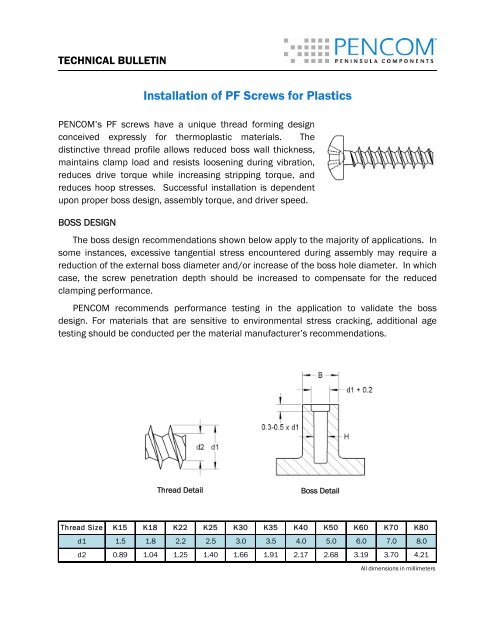
PENCOM’s <strong>PF</strong> screws have a unique thread <strong>for</strong>ming design<br />
conceived expressly <strong>for</strong> thermoplastic materials. The<br />
distinctive thread pr<strong>of</strong>ile allows reduced boss wall thickness,<br />
maintains clamp load and resists loosening during vibration,<br />
reduces drive torque while increasing stripping torque, and<br />
reduces hoop stresses. Successful installation is dependent<br />
upon proper boss design, assembly torque, and driver speed.<br />
BOSS DESIGN<br />
The boss design recommendations shown below apply to the majority <strong>of</strong> applications. In<br />
some instances, excessive tangential stress encountered during assembly may require a<br />
reduction <strong>of</strong> the external boss diameter and/or increase <strong>of</strong> the boss hole diameter. In which<br />
case, the screw penetration depth should be increased to compensate <strong>for</strong> the reduced<br />
clamping per<strong>for</strong>mance.<br />
PENCOM recommends per<strong>for</strong>mance testing in the application to validate the boss<br />
design. For materials that are sensitive to environmental stress cracking, additional age<br />
testing should be conducted per the material manufacturer’s recommendations.<br />
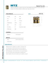
Thread Detail<br />
Boss Detail<br />
Thread Size K15 K18 K22 K25 K30 K35 K40 K50 K60 K70 K80<br />
d1 1.5 1.8 2.2 2.5 3.0 3.5 4.0 5.0 6.0 7.0 8.0<br />
d2 0.89 1.04 1.25 1.40 1.66 1.91 2.17 2.68 3.19 3.70 4.21<br />
All dimensions in millimeters
(Continued)<br />
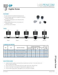
Material<br />
Hole<br />
Diameter<br />
H<br />
Boss<br />
Diameter<br />
B<br />
Minimum<br />
Thread<br />
Engagement<br />
Acrylonitrile butadiene styrene (ABS) .80 x d1 2.00 x d1 2.00 x d1<br />
Acrylonitrile butadiene styrene (ABS) / Polycarbonate (PC) Blend .80 x d1 2.00 x d1 2.00 x d1<br />
Acryonitrile Styrene Acrylate (ASA) .78 x d1 2.00 x d1 2.00 x d1<br />
Nylon 4/6 .73 x d1 1.85 x d1 1.80 x d1<br />
Nylon 4/6 30% Glass Filled .78 x d1 1.85 x d1 1.80 x d1<br />
Nylon 6 .75 x d1 1.85 x d1 1.70 x d1<br />
Nylon 6 30% Glass Filled .80 x d 1 2.00 x d1 1.90 x d1<br />
Nylon 6/6 .75 x d1 1.85 x d1 1.70 x d1<br />
Nylon 6/6 30% Glass Filled .82 x d1 2.00 x d1 1.80 x d1<br />
Polyamide (PPA) 15% Glass Filled .82 x d1 2.00 x d1 2.00 x d1<br />
Polybutylene terephthalate (PBT) .75 x d1 1.85 x d1 1.70 x d1<br />
Polybutylene terephthalate (PBT) 30% Glass Filled .80 x d1 1.80 x d1 1.70 x d1<br />
Polycarbonate (PC) .85 x d1 2.50 x d1 2.20 x d1<br />
Polycarbonate (PC) 30% Glass Filled .85 x d1 2.20 x d1 2.00 x d1<br />
Polyethylene (PE) .70 x d1 2.00 x d1 2.00 x d1<br />
Rigid Polyethylene (PE) .75 x d1 1.80 x d1 1.80 x d1<br />
Polyethylene terephthalate (PET) .75 x d1 1.85 x d1 1.70 x d1<br />
Polyethylene terephthalate (PET) 30% Glass Filled .80 x d1 1.80 x d1 1.70 x d1<br />
Polyoxymethylene (POM/Acetal) .75 x d1 1.95 x d1 2.00 x d1<br />
Polymethyl methacrylate (PMMA) * .85 x d1 2.00 x d1 2.00 x d1<br />
Polypropylene (PP) .70 x d1 2.00 x d1 2.00 x d1<br />
Polypropylene (PP) 20% Talc Filled .72 x d1 2.00 x d1 2.00 x d1<br />
Polyphenylene Oxide (PPO/Noryl) .85 x d1 2.50 x d1 2.20 x d1<br />
Polystyrene (PS) .80 x d1 2.00 x d1 2.00 x d1<br />
Rigid Polyvinyl Chloride (PVC) .80 x d1 2.00 x d1 2.00 x d1<br />
Styrene Acrylonitrile (SAN) .77 x d1 2.00 x d1 1.90 x d1<br />
* Boss dimensions strongly influenced by installation rpm<br />
ASSEMBLY TORQUE<br />
As clamping load increases so too does material relaxation and potential <strong>for</strong> stress<br />
cracking. There<strong>for</strong>e, PENCOM strongly encourages using the minimum necessary tightening<br />
torque rather than the maximum that can be achieved.<br />
DRIVER SPEED<br />
Friction between the screw threads and boss wall generates heat during installation.<br />
High driver rpm causes excessive heat that can melt the plastic and increase the likelihood<br />
<strong>of</strong> stripping failure during installation. As a guideline, 400-600 rpm generally results in a<br />
proper installation while maintaining high productivity. However, the driver rpm should be<br />
tested in the application and adjusted as necessary.<br />
This in<strong>for</strong>mation may be update periodically. Contact <strong>Pencom</strong> <strong>for</strong> current in<strong>for</strong>mation or see www.pencomsf.com<br />
TB-<strong>PF</strong> INSTALLATION 06/28/12 © <strong>Pencom</strong> 2012