Ball Studs and Clips - Pencom
Ball Studs and Clips - Pencom
Ball Studs and Clips - Pencom

Create successful ePaper yourself
Turn your PDF publications into a flip-book with our unique Google optimized e-Paper software.
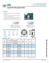
BS / BSC<br />
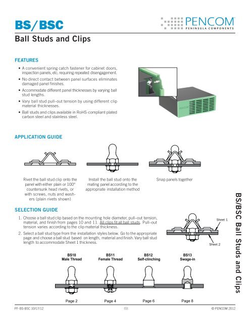
<strong>Ball</strong> <strong>Studs</strong> <strong>and</strong> <strong>Clips</strong><br />
Features<br />
• A convenient spring catch fastener for cabinet doors,<br />
inspection panels, etc. requiring repeated disengagement.<br />
• No direct contact between panel surfaces eliminates<br />
damaged panel finishes.<br />
• Accommodate different panel thicknesses by varying ball<br />
stud lengths.<br />
• Vary ball stud pull–out tension by using different clip<br />
material thicknesses.<br />
• <strong>Ball</strong> studs <strong>and</strong> clips available in RoHS-compliant plated<br />
carbon steel <strong>and</strong> stainless steel.<br />
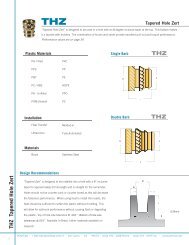
APPLICATION GUIDE<br />
Rivet the ball stud clip onto the<br />
panel with either plain or 100°<br />
countersunk head rivets, or<br />
with screws, nuts <strong>and</strong> washers<br />
(plain rivets shown)<br />
SELECTION GUIDE<br />
Install the ball stud onto the<br />
mating panel according to the<br />
appropriate installation method<br />
1. Choose a ball stud clip based on the mounting hole diameter, pull–out tension,<br />
material, <strong>and</strong> finish from pages 10 <strong>and</strong> 11. All clips fit all ball studs. Pull–out<br />
tension varies according to the clip material thickness.<br />
2. Select a ball stud type from the installation styles below. Go to the appropriate<br />
page <strong>and</strong> choose a ball stud based on length, material <strong>and</strong> finish. Vary ball stud<br />
length to accommodate Sheet 1 thickness.<br />
BS10<br />
Male Thread<br />
BS11<br />
Female Thread<br />
BS12<br />
Self-clinching<br />
Snap panels together<br />
BS13<br />
Swage-in<br />
Sheet 2<br />
Sheet 1<br />
BS/BSC <strong>Ball</strong> <strong>Studs</strong> <strong>and</strong> <strong>Clips</strong><br />
Page 2 Page 4 Page 6 Page 8<br />
PF-BS-BSC 10/17/12 (1)<br />
© PENCOM 2012
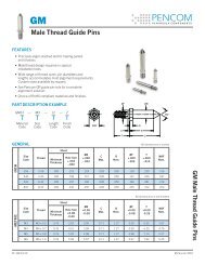
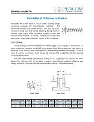
BS10<br />
Male Thread <strong>Ball</strong> <strong>Studs</strong><br />
Part Description Example<br />
BS10 — 473 — 8 — STL — Z<br />
.156<br />
(3.96)<br />
.231<br />
(5.87)<br />
Series<br />
Length<br />
Code<br />
Thread<br />
Length<br />
Code<br />
Material<br />
Code<br />
Finish<br />
Code<br />
.187<br />
(4.75)<br />
.102 (2.59)<br />
S<br />
.250<br />
(6.35)<br />
L<br />
T<br />
GENERAL<br />
All dimensions in inches<br />
Thread<br />
Series<br />
Sheet 1<br />
Thickness<br />
Length<br />
Code<br />
L<br />
±.010<br />
S<br />
±.005<br />
.025-.051 421 .421 .328<br />
INCH<br />
METRIC<br />
6-32<br />
UNC-2A<br />
Thread<br />
M3.5 x 0.5<br />
6g<br />
BS10<br />
Series<br />
BS10M<br />
(1) Refer to page 1 for sheet description<br />
.052-.078 447 .447 .354<br />
.079-.105 473 .473 .380<br />
.106-.132 499 .499 .406<br />
.133-.159 525 .525 .432<br />
.160-.187 551 .551 .458<br />
.177-.203 570 .570 .477<br />
.230-.256 625 .625 .532<br />
Sheet 1<br />
Thickness<br />
Length<br />
Code<br />
All dimensions in millimeters<br />
L<br />
±0.25<br />
S<br />
±0.13<br />
0.64-1.30 1069 10.69 8.33<br />
1.31-1.98 1135 11.35 8.99<br />
1.99-2.67 1201 12.01 9.65<br />
2.68-3.35 1267 12.67 10.31<br />
3.36-4.04 1334 13.34 10.97<br />
4.05-4.75 1400 14.00 11.63<br />
4.50-5.16 1448 14.48 12.12<br />
5.84-6.50 1588 15.88 13.51<br />
PENCOM carries a wide assortment<br />
of st<strong>and</strong>ard <strong>and</strong> selfclinching<br />
nut <strong>and</strong> washer<br />
assemblies <strong>and</strong> components.<br />
Contact a PENCOM Account<br />
Manager for recommendations<br />
<strong>and</strong> more information.<br />
BS10 Male Thread <strong>Ball</strong> <strong>Studs</strong><br />
PF-BS-BSC 10/17/12 (2)<br />
© PENCOM 2012
www.pencomsf.com<br />
THREAD LENGTH<br />
Thread<br />
Length<br />
Code<br />
T<br />
+.010<br />
-.000<br />
5 .156<br />
Thread<br />
Length<br />
Code<br />
T<br />
+0.25<br />
-0.00<br />
400 4.00<br />
OPTION<br />
6 .187<br />
500 5.00<br />
INCH<br />
7 .218<br />
8 .250<br />
10 .312<br />
12 .375<br />
14 .437<br />
16 .500<br />
18 .562<br />
20 .625<br />
22 .687<br />
All dimensions in inches<br />
METRIC<br />
600 6.00<br />
750 7.50<br />
900 9.00<br />
1050 10.50<br />
1200 12.00<br />
1350 13.50<br />
1500 15.00<br />
1650 16.50<br />
1800 18.00<br />
All dimensions in millimeters<br />
A variety of thread locking <strong>and</strong> lubricating materials<br />
can be applied to the threads. Nylon<br />
(shown), micro—encapsulated epoxy <strong>and</strong> other<br />
locking elements prevent loosening due to vibration.<br />
Lubricating coatings reduce friction, heat<br />
buildup <strong>and</strong> galling during installation of mating<br />
fasteners.To specify a nylon locking element, insert<br />
PATCH at the end of the part description. Other locking<br />
<strong>and</strong> lubricating materials available by request.<br />
Ex: BS10-473-8-STL-Z-PATCH<br />
MATERIAL & FINISH<br />
Material<br />
Code<br />
Material Description<br />
Finish<br />
Code<br />
Finish Description<br />
STL Carbon Steel Z Zinc SC1 with Type III Clear Chromate per ASTM B 633<br />
SS 300-Series Stainless Steel P Passivated <strong>and</strong>/or Tested per ASTM A 967<br />
INSTALLATION<br />
1. Punch or drill hole in sheet. Insert the ball stud male thread through hole in<br />
sheet <strong>and</strong> secure with female threaded fastener. In some applications it<br />
may be desirable to install a washer between the female threaded fastener<br />
<strong>and</strong> sheet.<br />
2. Tighten the assembly by torquing the female threaded fastener 5.8 to<br />
7.9 in-lbs (6-32) or 0.53 to 0.72 N-m (M3.5). PENCOM recommends<br />
a minimum thread engagement of .138 in (6-32) or 3.5 mm (M3.5) between<br />
the male <strong>and</strong> female threads. Installation torques are for zinc–plated<br />
carbon steel ball studs <strong>and</strong> nuts, <strong>and</strong> for reference only. <strong>Pencom</strong><br />
recommends testing in the application.<br />
3. Due to the inelastic nature <strong>and</strong> unpredictable friction coefficients of<br />
stainless steel, torque calculations for this material can be unreliable.<br />
One method of determining the installation torque uses 50% of the<br />
failure torque as developed through testing in the application <strong>and</strong><br />
applying a ±20% tolerance.<br />
BS10 Male Thread <strong>Ball</strong> <strong>Studs</strong><br />
PF-BS-BSC 10/17/12 (3)<br />
© PENCOM 2012
BS11<br />
Female Thread <strong>Ball</strong> <strong>Studs</strong><br />
Part Description Example<br />
BS11 — 473 — STL — Z<br />
.156<br />
(3.96)<br />
.231<br />
(5.87)<br />
Series<br />
Length<br />
Code<br />
Material<br />
Code<br />
Finish<br />
Code<br />
.187<br />
(4.75)<br />
.102 (2.59)<br />
D<br />
Min.<br />
S<br />
.250<br />
(6.35)<br />
L<br />
GENERAL<br />
All dimensions in inches<br />
Thread<br />
Series<br />
Sheet 1<br />
Thickness<br />
Length<br />
Code<br />
L<br />
±.010<br />
S<br />
±.005<br />
D<br />
Min.<br />
.025-.051 421 .421 .328 .185<br />
INCH<br />
METRIC<br />
6-32<br />
UNC-2B<br />
Thread<br />
M3.5 x 0.5<br />
6H<br />
BS11<br />
Series<br />
BS11M<br />
(1) Refer to page 1 for sheet description.<br />
.052-.078 447 .447 .354 .211<br />
.079-.105 473 .473 .380 .237<br />
.106-.132 499 .499 .406 .263<br />
.133-.159 525 .525 .432 .289<br />
.160-.187 551 .551 .458 .315<br />
.177-.203 570 .570 .477 .334<br />
.230-.256 625 .625 .532 .389<br />
Sheet 1<br />
Thickness<br />
Length<br />
Code<br />
L<br />
±0.25<br />
All dimensions in millimeters<br />
S<br />
±0.13<br />
D<br />
Min.<br />
0.64-1.30 1069 10.69 8.33 4.70<br />
1.31-1.98 1135 11.35 8.99 5.36<br />
1.99-2.67 1201 12.01 9.65 6.02<br />
2.68-3.35 1267 12.67 10.31 6.68<br />
3.36-4.04 1334 13.34 10.97 7.34<br />
4.05-4.75 1400 14.00 11.63 8.00<br />
4.50-5.16 1448 14.48 12.12 8.48<br />
5.84-6.50 1588 15.88 13.51 9.88<br />
PENCOM carries a wide assortment<br />
of screw <strong>and</strong> washer<br />
assemblies <strong>and</strong> components.<br />
Contact a PENCOM Account<br />
Manager for recommendations<br />
<strong>and</strong> more information.<br />
BS11 Female Thread <strong>Ball</strong> <strong>Studs</strong><br />
PF-BS-BSC 10/17/12 (4)<br />
© PENCOM 2012
www.pencomsf.com<br />
MATERIAL & FINISH<br />
Material<br />
Code<br />
Material Description<br />
Finish<br />
Code<br />
Finish Description<br />
STL Carbon Steel Z Zinc SC1 with Type III Clear Chromate per ASTM B 633<br />
SS 300-Series Stainless Steel P Passivated <strong>and</strong>/or Tested per ASTM A 967<br />
INSTALLATION<br />
1. Punch or drill hole in sheet. Insert a male thread fastener through<br />
hole in the sheet <strong>and</strong> secure the ball stud. In some applications it<br />
may be desirable to install a washer between the head of the male<br />
threaded fastener <strong>and</strong> sheet.<br />
2. Tighten the assembly by torquing the male threaded fastener 7 to<br />
10 in-lbs (6-32) or 0.8 to 1.1 N-m (M3.5). PENCOM recommends<br />
a minimum thread engagement of .138 in (6-32) or 3.5 mm (M3.5)<br />
between the male <strong>and</strong> female threads. Installation torques are for<br />
zinc–plated Grade 2 (inch) or Class 4.8 (metric) carbon steel screws<br />
<strong>and</strong> for reference only. PENCOM recommends testing in the application.<br />
3. Due to the inelastic nature <strong>and</strong> unpredictable friction coefficients<br />
of stainless steel, torque calculations for this material can be unreliable.<br />
One method of determining the installation torque uses 50% of the<br />
failure torque as developed through testing in the application <strong>and</strong><br />
applying a ±20% tolerance.<br />
BS11 Female Thread <strong>Ball</strong> <strong>Studs</strong><br />
PF-BS-BSC 10/17/12 (5)<br />
© PENCOM 2012
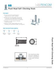
BS12<br />
Self–clinching <strong>Ball</strong> <strong>Studs</strong><br />
Part Description Example<br />
BS12 — 466 — STL — Z<br />
Ø.156<br />
(Ø3.96)<br />
.231<br />
(5.87)<br />
Length<br />
Code<br />
Material<br />
Code<br />
Finish<br />
Code<br />
.187<br />
(4.75)<br />
.280/.275<br />
(7.12/6.99)<br />
.102 (2.59)<br />
S<br />
.326 (8.28)<br />
L<br />
GENERAL<br />
All dimensions in inches (millimeters)<br />
Sheet 1<br />
Thickness<br />
Sheet 2<br />
Thickness<br />
Length<br />
Code<br />
L<br />
±.010<br />
(±0.25)<br />
S<br />
±.005<br />
(±0.13)<br />
.040-.049 (1.02-1.25) 466 .466 (11.84) .373 (9.47)<br />
.025-.051 (0.64-1.30)<br />
.050-.059 (1.27-1.50) 476 .476 (12.09) .383 (9.73)<br />
.040-.049 (1.02-1.25) 492 .492 (12.50) .399 (10.13)<br />
.052-.078 (1.31-1.98)<br />
.050-.059 (1.27-1.50) 502 .502 (12.75) .409 (10.39)<br />
.040-.049 (1.02-1.25) 518 .518 (13.16) .425 (10.80)<br />
.079-.105 (1.99-2.67)<br />
.050-.059 (1.27-1.50) 528 .528 (13.41) .435 (11.05)<br />
.040-.049 (1.02-1.25) 544 .544 (13.82) .451 (11.46)<br />
.106-.132 (2.68-3.35)<br />
.050-.059 (1.27-1.50) 554 .554 (14.07) .461 (11.71)<br />
.040-.049 (1.02-1.25) 570 .570 (14.48) .477 (12.12)<br />
.133-.159 (3.36-4.04)<br />
.050-.059 (1.27-1.50) 580 .580 (14.73) .487 (12.37)<br />
.040-.049 (1.02-1.25) 596 .596 (15.14) .503 (12.78)<br />
.160-.187 (4.05-4.75)<br />
.050-.059 (1.27-1.50) 606 .606 (15.39) .513 (13.03)<br />
.040-.049 (1.02-1.25) 615 .615 (15.62) .522 (13.26)<br />
.177-.203 (4.50-5.16)<br />
.050-.059 (1.27-1.50) 625 .625 (15.88) .532 (13.51)<br />
.040-.049 (1.02-1.25) 670 .670 (17.02) .577 (14.66)<br />
.230-.256 (5.84-6.50)<br />
.050-.059 (1.27-1.50) 680 .680 (17.27) .587 (14.91)<br />
(1) Refer to page 1 for sheet descriptions. <strong>Ball</strong> studs mount in sheet 2.<br />
BS12 Self–clinching <strong>Ball</strong> <strong>Studs</strong><br />
provide a permanent <strong>and</strong> reliable<br />
installation that creates a flush<br />
appearance on the back side<br />
of aluminum, carbon steel <strong>and</strong><br />
stainless steel sheets.<br />
BS12 Self–clinching <strong>Ball</strong> <strong>Studs</strong><br />
PF-BS-BSC 10/17/12 (6)<br />
© PENCOM 2012
www.pencomsf.com<br />
MATERIAL & FINISH<br />
Material<br />
Code<br />
Material Description<br />
Finish<br />
Code<br />
Finish Description<br />
For Use in Sheet Hardness<br />
HRB 70<br />
Max.<br />
HRB 80<br />
Max.<br />
HRB 88<br />
Max.<br />
STL Heat Treated Carbon Steel Z Zinc SC1 with Type III Clear Chromate per ASTM B 633 •<br />
SS 300-Series Stainless Steel P Passivated <strong>and</strong>/or Tested per ASTM A 967 •<br />
S4 Heat Treated Stainless Steel P Passivated <strong>and</strong>/or Tested per ASTM A 967 •<br />
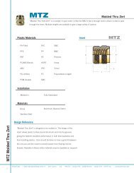
INSTALLATION<br />
1. Punch or drill hole in sheet a minimum<br />
distance of .37in (9.4mm) from the hole<br />
center to edge of sheet. Do not deburr<br />
edges.<br />
Punch<br />
Sheet<br />
.284/.281<br />
(7.21/7.13)<br />
Sheet 2 Hole Detail<br />
2. Insert the ball stud through hole in sheet<br />
<strong>and</strong> into the anvil as shown.<br />
3. Squeeze the sheet <strong>and</strong> ball stud head<br />
between parallel punch <strong>and</strong> anvil<br />
surfaces. Use only enough pressure to<br />
seat the ball stud head flush with the<br />
sheet. Punch <strong>and</strong> anvil should be made<br />
from hardened steel.<br />
L Min.<br />
.287/.284<br />
(7.29/7.21)<br />
Anvil<br />
Installed<br />
PERFORMANCE<br />
<strong>Ball</strong><br />
Stud<br />
Material<br />
Code<br />
STL<br />
SS<br />
Installation<br />
lbs<br />
(kN)<br />
1700-2000<br />
(7.6-8.9)<br />
1700-2000<br />
(7.6-8.9)<br />
.50 (12.7) Min.<br />
Test Sheet Material<br />
5052-H32 Aluminum 1008 Carbon Steel HRB 60 304 Stainless Steel HRB 70<br />
Push–out<br />
lbs<br />
(N)<br />
230<br />
(1023)<br />
230<br />
(1023)<br />
Installation<br />
lbs<br />
(kN)<br />
3600-4400<br />
(16.0-19.6)<br />
3600-4400<br />
(16.0-19.6)<br />
Push–out<br />
lbs<br />
(N)<br />
360<br />
(1601)<br />
360<br />
(1601)<br />
S4 — — — —<br />
Installation<br />
lbs<br />
(kN)<br />
Push–out<br />
lbs<br />
(N)<br />
(2) (2)<br />
(2) (2)<br />
5900-7200<br />
(26.2-32.0)<br />
470<br />
(2090)<br />
(1) Performance data represents the average destructive result when all installation specifications are strictly followed. Variations in sheet hole<br />
size, thickness, material <strong>and</strong> installation methods will affect the loads. PENCOM strongly encourages testing in the application.<br />
(2) Not recommended.<br />
BS12 Self–clinching <strong>Ball</strong> <strong>Studs</strong><br />
PF-BS-BSC 10/17/12 (7)<br />
© PENCOM 2012
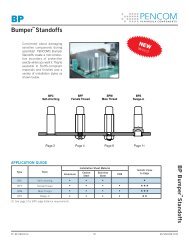
BS13<br />
Swage–in <strong>Ball</strong> <strong>Studs</strong><br />
Part Description Example<br />
BS13 — 473 — B — SS — P<br />
.156<br />
(3.96)<br />
.231<br />
(5.87)<br />
.153/.150<br />
(3.89/3.81)<br />
.188/.185<br />
(4.78/4.70)<br />
Length<br />
Code<br />
Shank<br />
Length<br />
Code<br />
Material<br />
Code<br />
Finish<br />
Code<br />
.187<br />
(4.75)<br />
.102 (2.59)<br />
S<br />
.282/.272<br />
(7.16/6.91)<br />
L<br />
T<br />
GENERAL<br />
All dimensions in inches (millimeters)<br />
Sheet 1<br />
Thickness<br />
Length<br />
Code<br />
L<br />
±.010<br />
(±0.25)<br />
S<br />
±.005<br />
(±0.13)<br />
Anvil<br />
A<br />
.025-.051 (0.64-1.30) 421 .421 (10.69) .328 (8.33) .313 (7.95)<br />
.052-.078 (1.31-1.98) 447 .447 (11.35) .354 (8.99) .339 (8.61)<br />
.079-.105 (1.99-2.67) 473 .473 (12.01) .380 (9.65) .365 (9.27)<br />
.106-.132 (2.68-3.35) 499 .499 (12.67) .406 (10.31) .391 (9.93)<br />
.133-.159 (3.36-4.04) 525 .525 (13.34) .432 (10.97) .417 (10.59)<br />
.160-.187 (4.05-4.75) 551 .551 (14.00) .458 (11.63) .443 (11.25)<br />
.177-.203 (4.50-5.16) 570 .570 (14.48) .477 (12.12) .462 (11.73)<br />
.230-.256 (5.84-6.50) 625 .625 (15.88) .532 (13.51) .517 (13.13)<br />
(1) Refer to page 1 for sheet description.<br />
SHANK LENGTH<br />
Sheet 2 Thickness<br />
Swage–In<br />
Flare–In<br />
Min.<br />
Shank<br />
Length<br />
Code<br />
T<br />
±.003<br />
(±0.08)<br />
Sheet<br />
B<br />
.031 (0.79) .095 (2.41) A .075 (1.91) .015 (0.38)<br />
.062 (1.59) .125 (3.18) B .105 (2.67) .035 (0.89)<br />
.094 (2.38) .155 (3.94) C .135 (3.43) .065 (1.65)<br />
.125 (3.18) .185 (4.70) D .165 (4.19) .095 (2.41)<br />
.187 (4.76) .250 (6.35) E .230 (5.84) .160 (4.06)<br />
.250 (6.35) .310 (7.87) F .290 (7.37) .220 (5.59)<br />
(1) Refer to page 1 for sheet description.<br />
All dimensions in inches (millimeters)<br />
BS13 Swage–in <strong>Ball</strong> <strong>Studs</strong><br />
can be flared in as well <strong>and</strong><br />
are popular choices for painted<br />
sheets <strong>and</strong> close–to–edge<br />
applications (swaged installation<br />
shown).<br />
BS13 Swage–in <strong>Ball</strong> <strong>Studs</strong><br />
PF-BS-BSC 10/17/12 (8)<br />
© PENCOM 2012
www.pencomsf.com<br />
MATERIAL & FINISH<br />
Material<br />
Code<br />
Material Description<br />
Finish<br />
Code<br />
Finish Description<br />
SS 300–Series Stainless Steel P Passivated <strong>and</strong>/or Tested per ASTM A 967<br />
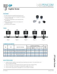
SWAGE–IN INSTALLATION<br />
1. Prepare the sheet as shown for swage–in installation.<br />
2. Insert the ball stud into recessed anvil <strong>and</strong> place<br />
sheet hole over ball stud shank.<br />
3. Squeeze the ball stud between parallel <strong>and</strong> concentric<br />
anvil <strong>and</strong> punch. Swage the ball stud shank using<br />
light pressure. Anvil should be made from hardened<br />
steel. Punch may be ordered using PENCOM part<br />
number TL1197.<br />
FLARE–IN INSTALLATION<br />
1. Prepare the sheet as shown for flare–in installation.<br />
2. Insert the ball stud into recessed anvil <strong>and</strong> place sheet<br />
hole over ball stud shank.<br />
3. Squeeze the ball stud between parallel <strong>and</strong> concentric<br />
anvil <strong>and</strong> punch. Flare the ball stud shank into the<br />
sheet countersink using light pressure. Punch flare<br />
angle should match the sheet hole countersink angle.<br />
Anvil <strong>and</strong> punch should be made from hardened steel.<br />
.50<br />
(12.7)<br />
<strong>Pencom</strong><br />
Punch<br />
TL1197<br />
Punch<br />
92°/88°<br />
A<br />
118°<br />
.50 (12.7) Min.<br />
Sheet<br />
Anvil<br />
.287/.284<br />
(7.29/7.21)<br />
Swage-In Installation<br />
.193/.190<br />
(4.90/4.82)<br />
Sheet Hole Detail<br />
Installed<br />
A<br />
118°<br />
.50 (12.7) Min.<br />
Sheet<br />
Anvil<br />
.287/.284<br />
(7.29/7.21)<br />
Flare-In Installation<br />
.193/.190<br />
(4.90/4.82)<br />
Sheet Hole Detail<br />
Installed<br />
B<br />
BS13 Swage–in <strong>Ball</strong> <strong>Studs</strong><br />
PF-BS-BSC 10/17/12 (9)<br />
© PENCOM 2012
BSC<br />
<strong>Ball</strong> Stud <strong>Clips</strong><br />
Part Description Example<br />
H Dia. (2x)<br />
BSC — 135 — 017 — STL — Z<br />
B<br />
Hole<br />
Diameter<br />
Code<br />
Material<br />
Code<br />
Finish<br />
Code<br />
C<br />
A<br />
T<br />
E<br />
GENERAL<br />
All dimensions in inches (millimeters)<br />
Hole<br />
Diameter<br />
Code<br />
H<br />
Hole<br />
Diameter<br />
<strong>Ball</strong> Stud<br />
Pull-out<br />
Tension<br />
lbs (N)<br />
±30%<br />
Material<br />
Thickness<br />
Code<br />
T<br />
Material<br />
Thickness<br />
A B C E<br />
3.5 (15) 012 .012 (0.30)<br />
105<br />
.105<br />
(2.67)<br />
8.0 (35) 017 .017 (0.43)<br />
12.0 (53) 022 .022 (0.56)<br />
18.0 (80) 028 .028 (0.71)<br />
.970<br />
(24.64)<br />
.440<br />
(11.18)<br />
.685<br />
(17.40)<br />
.220<br />
(5.59)<br />
30.0 (133) 031 .031 (0.79)<br />
3.5 (15) 012 .012 (0.30)<br />
135<br />
145<br />
.135<br />
(3.43)<br />
.145<br />
(3.68)<br />
8.0 (35) 017 .017 (0.43)<br />
12.0 (53) 022 .022 (0.56)<br />
18.0 (80) 028 .028 (0.71)<br />
30.0 (133) 031 .031 (0.79)<br />
3.5 (15) 012 .012 (0.30)<br />
8.0 (35) 017 .017 (0.43)<br />
12.0 (53) 022 .022 (0.56)<br />
18.0 (80) 028 .028 (0.71)<br />
30.0 (133) 031 .031 (0.79)<br />
(1) All dimensions are reference unless toleranced.<br />
.970<br />
(24.64)<br />
.970<br />
(24.64)<br />
.440<br />
(11.18)<br />
.440<br />
(11.18)<br />
.685<br />
(17.40)<br />
.685<br />
(17.40)<br />
.220<br />
(5.59)<br />
.220<br />
(5.59)<br />
BSC <strong>Ball</strong> Stud <strong>Clips</strong><br />
PF-BS-BSC 10/17/12 (10)<br />
© PENCOM 2012
www.pencomsf.com<br />
MATERIAL & FINISH<br />
Material<br />
Code<br />
Material Description<br />
Finish<br />
Code<br />
Finish Description<br />
STL Carbon Steel Z Zinc SC1 with Type III Clear Chromate per ASTM B 633<br />
STL Carbon Steel OIL Soluble Oil<br />
STL Carbon Steel PHOS-OIL Phosphate with Oil<br />
SS 300-Series Stainless Steel P Passivated <strong>and</strong>/or Tested per ASTM A 967<br />
(1) Other finishes available by request.<br />
INSTALLATION<br />
1. Drill or punch clip mounting <strong>and</strong> ball stud clearance holes in sheet.<br />
2. Rivet the ball stud clip onto the sheet with either plain or 100° countersunk head rivets (plain rivet installatoin<br />
shown on left) or with screws, nuts <strong>and</strong> washers (shown on right).<br />
BSC <strong>Ball</strong> Stud <strong>Clips</strong><br />
PF-BS-BSC 10/17/12 (11)<br />
© PENCOM 2012