Pentair Clean & Clear Plus Cartridge Filter Owners ... - Pool Center
Pentair Clean & Clear Plus Cartridge Filter Owners ... - Pool Center
Pentair Clean & Clear Plus Cartridge Filter Owners ... - Pool Center

You also want an ePaper? Increase the reach of your titles
YUMPU automatically turns print PDFs into web optimized ePapers that Google loves.
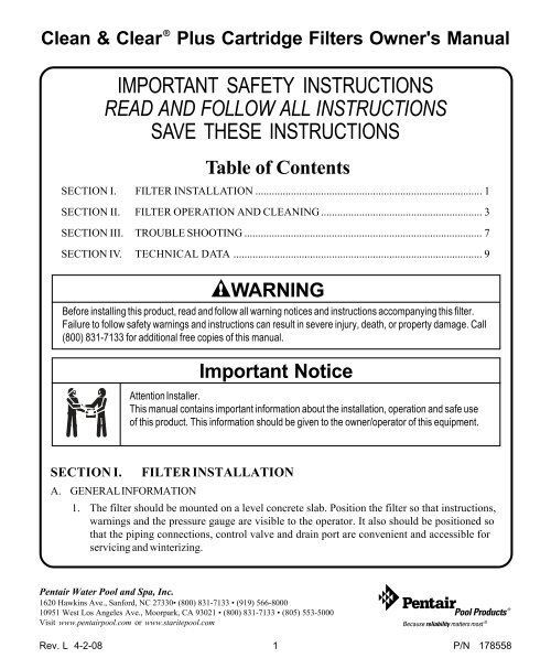
<strong>Clean</strong> & <strong>Clear</strong> ®<br />
<strong>Plus</strong> <strong>Cartridge</strong> <strong>Filter</strong>s Owner's Manual<br />
IMPORTANT SAFETY INSTRUCTIONS<br />
READ AND FOLLOW ALL INSTRUCTIONS<br />
SAVE THESE INSTRUCTIONS<br />
Table of Contents<br />
SECTION I. FILTER INSTALLATION ................................................................................... 1<br />
SECTION II. FILTER OPERATION AND CLEANING ........................................................... 3<br />
SECTION III. TROUBLE SHOOTING ....................................................................................... 7<br />
SECTION IV. TECHNICAL DATA ........................................................................................... 9<br />
WARNING<br />
Before installing this product, read and follow all warning notices and instructions accompanying this filter.<br />
Failure to follow safety warnings and instructions can result in severe injury, death, or property damage. Call<br />
(800) 831-7133 for additional free copies of this manual.<br />
Important Notice<br />
Attention Installer.<br />
This manual contains important information about the installation, operation and safe use<br />
of this product. This information should be given to the owner/operator of this equipment.<br />
SECTION I.<br />
FILTER INSTALLATION<br />
A. GENERAL INFORMATION<br />
1. The filter should be mounted on a level concrete slab. Position the filter so that instructions,<br />
warnings and the pressure gauge are visible to the operator. It also should be positioned so<br />
that the piping connections, control valve and drain port are convenient and accessible for<br />
servicing and winterizing.<br />
<strong>Pentair</strong> Water <strong>Pool</strong> and Spa, Inc.<br />
1620 Hawkins Ave., Sanford, NC 27330• (800) 831-7133 • (919) 566-8000<br />
10951 West Los Angeles Ave., Moorpark, CA 93021 • (800) 831-7133 • (805) 553-5000<br />
Visit www.pentairpool.com or www.staritepool.com<br />
Rev. L 4-2-08 1 P/N 178558
2. Be certain to install electrical controls (e.g., on/off<br />
switches, timers, control systems, etc.) at least five (5)<br />
feet from the filter. This permits one to stand clear of the<br />
filter during system start up.<br />
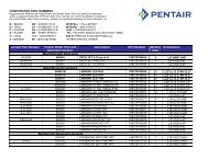
3. Allow sufficient clearance around the filter to permit<br />
visual verification that the clamp is properly installed<br />
around the tank flanges, see Figure A.<br />
a. Tap the clamp with a mallet or similar tool to ensure<br />
uniform loading during clamp tightening.<br />
4. Allow sufficient space above the filter to remove the filter<br />
lid for cleaning and servicing. This distance<br />
will vary with the model of filter you are using.<br />
See Table 1 for the required vertical clearance.<br />
5. Position the filter to safely direct water<br />
drainage. Rotate the High Flow manual air<br />
relief valve to safely direct purged air or water.<br />
Water discharged from an improperly<br />
positioned filter or valve can create an<br />
electrical hazard as well as damage property.<br />
WARNING<br />
6. Make all plumbing connections in accordance with local plumbing and building codes. <strong>Filter</strong> plumbing<br />
connections are provided with an O-ring seal. If needed, use only a silicone base lubricant on the<br />
O-rings. Do not use pipe joint compound, glue or solvent on the bulkhead connections.<br />
NOTE<br />
On threaded valve connections use only Teflon ® tape, 100% Teflon ® tape, 100% Teflon ® paste, or Permatex ® #2<br />
to seal the threads.<br />
7. Remove the plug from the top of the filter lid and install the pressure gauge before use.<br />
Figure A.<br />
Table 1.<br />
Model No. P/N Size Vert. <strong>Clear</strong>ance<br />
Req.<br />
CCP240 160310 240 sq. ft. 56 in.<br />
CCP320 160340 320 sq. ft. 62 in.<br />
CCP420 160301 420 sq. ft. 68 in.<br />
CCP520 160332 520 sq. ft. 74 in.<br />
Risk of electrical shock or electrocution. Position the filter and High Flow manual air relief valve to safely<br />
direct water drainage and purged air or water. Water discharged from an improperly positioned filter or<br />
valve can create an electrical hazard that can cause severe personal injury as well as damage property.<br />
8. The maximum working pressure of this filter is 50 p.s.i. Never subject this filter to pressure in<br />
excess of this amount, even when conducting hydrostatic pressure tests. Pressures above 50 p.s.i.<br />
can cause the lid to be blown off, which can result in severe injury, death or property damage.<br />
When performing hydrostatic pressure tests or when testing for external leaks of the<br />
completed filtration and plumbing system, insure that the MAXIMUM PRESSURE that the<br />
filtration system will be subjected to DOES NOT EXCEED THE MAXIMUM WORKING<br />
PRESSURE OF ANY OF THE COMPONENTS CONTAINED WITHIN THE SYSTEM. In<br />
most cases, the maximum pressure will be stated on each component of the system.<br />
P/N 178558 2 Rev. L 4-2-08
If doubt exists as to the pressure to which the system will be subjected, install an ASME<br />
approved automatic Pressure Relief or Pressure Regulator in the circulation system for the<br />
lowest working pressure of any of the components in the system.<br />
SECTION II. FILTER OPERATION AND CLEANING<br />
WARNING<br />
THIS FILTER OPERATES UNDER HIGH PRESSURE. WHEN ANY PART OF THE<br />
CIRCULATING SYSTEM (e.g., FILTER LID, PUMP, FILTER, VALVES, ETC.) IS SERVICED,<br />
AIR CAN ENTER THE SYSTEM AND BECOME PRESSURIZED. PRESSURIZED AIR CAN<br />
CAUSE THE LID TO BLOW OFF WHICH CAN RESULT IN SEVERE INJURY, DEATH, OR<br />
PROPERTY DAMAGE. TO AVOID THIS POTENTIAL HAZARD, FOLLOW THESE<br />
INSTRUCTIONS.<br />
1. BEFORE REPOSITIONING VALVES AND BEFORE BEGINNING THE ASSEMBLY,<br />
DISASSEMBLY, OR ADJUSTMENT OF THE LID OR ANY OTHER SERVICE OF THE<br />
CIRCULATING SYSTEM: (A) TURN THE PUMP OFF AND SHUT OFF ANY AUTOMATIC<br />
CONTROLS TO ASSURE THE SYSTEM IS NOT INADVERTENTLY STARTED DURING<br />
THE SERVICING. (B) OPEN AIR RELIEF VALVE, AND (C) WAIT UNTIL ALL PRESSURE IS<br />
RELIEVED - PRESSURE GAUGE MUST READ ZERO (0 psi).<br />
2. WHENEVER INSTALLING THE FILTER LID, FOLLOW THE FILTER LID INSTALLATION<br />
INSTRUCTIONS EXACTLY.<br />
3. ONCE SERVICE ON THE CIRCULATING SYSTEM IS COMPLETE, FOLLOW SYSTEM<br />
RESTART INSTRUCTIONS EXACTLY.<br />
4. MAINTAIN CIRCULATION SYSTEM PROPERLY. REPLACE WORN OR DAMAGED PARTS<br />
IMMEDIATELY (e.g., lid, knob, pressure gauge, relief valve, O-rings, etc.)<br />
5. BE SURE THAT THE FILTER IS PROPERLY MOUNTED AND POSITIONED ACCORDING<br />
TO INSTRUCTIONS PROVIDED.<br />
A. GENERAL INFORMATION<br />
1. This filter operates under pressure. When clamped properly and operated without air in the<br />
circulating system, this filter will operate in a safe manner.<br />
2. The maximum working pressure of this filter is 50 p.s.i. Never subject this filter to pressure in<br />
excess of this amount - even when conducting hydrostatic pressure tests. Pressures above 50 p.s.i.<br />
can cause the lid to be blown off, which can result in severe injury, death or property damage.<br />
When performing hydrostatic pressure tests or when testing for external leaks of the<br />
completed filtration and plumbing system, insure that the MAXIMUM PRESSURE that the<br />
filtration system will be subjected to DOES NOT EXCEED THE MAXIMUM WORKING<br />
PRESSURE OF ANY OF THE COMPONENTS CONTAINED WITHIN THE SYSTEM. In<br />
most cases, the maximum pressure will be stated on each component of the system.<br />
If doubt exists as to the pressure to which the system will be subjected, install an ASME<br />
approved automatic Pressure Relief or Pressure Regulator in the circulation system for the<br />
lowest working pressure of any of the components in the system.<br />
Rev. L 4-2-08 3 P/N 178558
3. The pressure gauge is the primary indicator of how the filter is operating. Maintain your pressure<br />
gauge in good working order.<br />
WARNING<br />
Your filter is a piece of machinery, do not tamper with it, attempt to disassemble it or otherwise<br />
adjust it unless you fully understand it's operation. Serious injury or death can occur if the equipment<br />
is improperly handled. Consult a pool service professional for maintenance and service assistance.<br />
4. <strong>Clean</strong> your filter when pressure reads between 8-10 p.s.i. higher than the original starting pressure.<br />
Your filter pressure reading will increase as it removes dirt from your pool. However, this buildup of<br />
pressure will vary due to different bathing loads, temperature, weather conditions, etc.<br />
a. MY ORIGINAL STARTING PRESSURE IS ___________ psi (pounds per square inch).<br />
I SHOULD CLEAN THE FILTER CARTRIDGE ELEMENT AT __________ psi.<br />
NOTE<br />
For first time operation on new pools introduce into the system .75 pounds of diatomaceous earth per every<br />
100 square feet of filter area (a one-pound coffee can equals .5 pounds of diatomaceous earth). Mix the diatomite<br />
with water and pour it into the skimmer after the pump is primed and the system is operating. This will enhance<br />
the filtration of your water.<br />
B. CLAMP INSTALLATION INSTRUCTIONS<br />
These instructions MUST BE FOLLOWED EXACTLY to prevent the lid from<br />
blowing off during system restart or later operation:<br />
1. Perform the following procedures before working on any part of the circulating system (e.g., clamp,<br />
pump, filter, valves, etc.).<br />
a. Turn the pump off and shut off any automatic controls to ensure that the system is not<br />
inadvertently started during servicing.<br />
b. Open the High Flow manual air relief valve.<br />
c. Wait until all pressure is relieved. Never attempt to assemble, disassemble or adjust the<br />
filter clamp while there is any pressure in the filter.<br />
2. Be certain the O-ring is in position in the lower tank half. Place the filter lid over the lower tank half<br />
sandwiching the O-ring in between.<br />
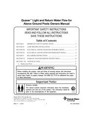
3. Holding the ends of the filter clamp apart, position the center segment of the filter clamp over both<br />
upper and lower tank flanges. Bring the<br />
ends of the filter clamp together and insert<br />
the T-Bolt into the trunnion; see Figure B.<br />
4. Using Figure B as a guide, place washer<br />
(large I.D.) and tension-indicating spring<br />
on the barrel nut. Place the second washer<br />
(small I.D.) on T-Bolt. Hand-tighten nut.<br />
Recheck filter clamp for proper seating on<br />
tank flanges.<br />
Figure B.<br />
P/N 178558 4 Rev. L 4-2-08
5. Begin to tighten nut using a 7/8" wrench. Then tap around the outside of the filter clamp with a<br />
mallet (or similar tool) to insure uniform loading and proper seating of the clamp. Continue tapping<br />
and tightening until the spring coils touch each other. Do not tighten beyond this point.<br />
6. Follow the procedures in Section C, System Restart Instructions.<br />
7. The spring coils should be checked at least once per month to ensure that they continue to touch<br />
each other, indicating that the clamp is under sufficient tension. If coils fail to touch repeat Step<br />
B.5 in this section, above.<br />
C. SYSTEM RESTART INSTRUCTIONS<br />
WARNING<br />
THIS FILTER OPERATES UNDER HIGH PRESSURE. WHEN ANY PART OF THE<br />
CIRCULATING SYSTEM (e.g., CLAMP, PUMP, FILTER, VALVES, ETC.) IS SERVICED, AIR CAN<br />
ENTER THE SYSTEM AND BECOME PRESSURIZED. PRESSURIZED AIR CAN CAUSE THE<br />
LID TO BE BLOWN OFF WHICH CAN RESULT IN SEVERE INJURY, DEATH, OR PROPERTY<br />
DAMAGE. TO AVOID THIS POTENTIAL HAZARD, FOLLOW THESE INSTRUCTIONS.<br />
1. Open the High Flow manual air relief valve until it snaps into the full open position (this<br />
only requires a quarter turn counter-clockwise). Opening this valve rapidly releases air<br />
trapped in the filter.<br />
2. Stand clear of the filter tank, then start the pump.<br />
3. Close the High Flow manual air relief valve after a steady stream of water appears.<br />
4. The system is not working properly if either of the following conditions occur.<br />
a. A solid stream of water does not appear within 30 seconds after the pump's inlet basket fills<br />
with water.<br />
b. The pressure gauge indicates pressure before water outflow appears.<br />
If either condition exists, shut off the pump immediately, open valves in the water return line<br />
to relieve pressure, and clean the air relief valve, see Section F, <strong>Clean</strong>ing the High Flow<br />
manual air relief valve. If the problem persists, call (800) 831-7133 for assistance.<br />
D. CLEANING FILTER MANUALLY<br />
WARNING<br />
Operating the filter system without filter internal components installed can allow air to<br />
accumulate within the filter. Pressurized air can cause the lid to blow off which can result in<br />
severe injury, death or property damage. Always operate filter system with filter internal<br />
components installed.<br />
CAUTION<br />
The following information should be read carefully since it outlines the proper manner of care and operation for<br />
your filter system. As a result of following these instructions and taking the necessary preventative care, you can<br />
expect maximum efficiency and life from your filtration system.<br />
Rev. L 4-2-08 5 P/N 178558
1. Turn the pump off, shut off any automatic controls to ensure that the system is not inadvertently<br />
started during servicing.<br />
2. Open the filter High Flow manual air relief valve (and the waste drain valve or plug, if your<br />
system has one).<br />
3. Remove hair and lint strainer pot lid and clean basket. Replace basket and secure lid.<br />
4. Disconnect air relief valve drain hose if installed.<br />
5. Release tank clamp assembly and remove tank lid.<br />
6. Remove top manifold and cartridge element separately.<br />
7. Using a garden hose without a nozzle, direct water spray at cartridge element to dislodge and<br />
wash away accumulated foreign matter. Flush each cartridge inside and out.<br />
WARNING<br />
Please heed all manufacturers' posted instructions, warnings and cautions when using<br />
Baquacil ® or Baqua ® <strong>Clean</strong>.<br />
NOTE<br />
Special care must be taken when cleaning filter cartridges used in a swimming pool or spa using Baquacil ® as<br />
a sanitizer. Because of the way Baquacil ® works, the filter element must be cleaned more thoroughly and<br />
more frequently than in a chlorine system. If extreme care is not taken to completely remove all residue from<br />
the filter media a buildup will occur. This buildup will significantly shorten the life of the filter element.<br />
Baquacil ® is a mild coagulant which combines bacterial cells as well as other small particles contributed by the<br />
environment, bathers, etc. into particles large enough to be trapped by the filter. In comparison with all other trapped<br />
contaminants in a typical pool or spa the amount of bacterial cells that are deposited on the filter is minimal. The<br />
resulting deposit is a gray sticky film which can only be removed with Baqua ® <strong>Clean</strong>. If TSP or any TSP-type cleaner<br />
is used prior to stripping the film, the cleaner and the gray film will combine to form a gum-like substance. Once<br />
this occurs, the substance cannot be removed from the media and the filter cartridge must be replaced.<br />
8. Lift bottom manifold out of the tank and flush off any debris.<br />
9. Direct water spray to wash out the inside of the tank body. Water and debris will drain out<br />
through the open drain port.<br />
10. Check gasket around outer lip of bottom plate. Gasket must be firmly and evenly set in place. Do<br />
not use petroleum base lubricants to avoid damage to the gasket.<br />
11. Place bottom manifold, 4 cartridges, top manifold and air relief tube in place. Make sure the spring<br />
and standpipe assembly are retained on the top manifold. Ensure the air relief tube stays in an<br />
upright position. This is essential for the maximum air removal from inside the tank.<br />
12. Be certain the O-ring is in position in the lower tank half. Press the filter lid over the lower tank<br />
half and sandwich the O-ring in between.<br />
13. Replace tank top and carefully follow instructions in Section B, Clamp Installation Instructions.<br />
14. Replace drain plug and reinstall air relief valve drain hose if used.<br />
P/N 178558 6 Rev. L 4-2-08
E. REPLACING FILTER CARTRIDGES<br />
<strong>Filter</strong> cartridge element life will vary with pool conditions such as bather load, wind, dust,<br />
etc. You can expect an average cartridge life of 3 years under normal conditions.<br />
1. To replace cartridge element follow steps in Section D, <strong>Clean</strong>ing <strong>Filter</strong>, eliminating step D.7.<br />
F. CLEANING THE HIGH FLOW MANUAL AIR RELIEF VALVE<br />
1. Turn the pump off and shut off any automatic controls to ensure that the system is not<br />
inadvertently started during servicing.<br />
2. OPEN THE HIGH FLOW MANUAL AIR RELIEF VALVE UNTIL IT SNAPS INTO<br />
THE FULL OPEN POSITION, THEN WAIT UNTIL ALL PRESSURE IS RELIEVED.<br />
3. With the relief valve attached to the filter tank, pull out the locking tabs and remove the valve<br />
stem and cover assembly with a counter-clockwise and lifting motion, see Figure C.<br />
4. <strong>Clean</strong> debris from the valve stem and body. Verify that the filter tank's air passage is open by<br />
inserting a 5/16" drill bit through the valve body. Verify that the O-rings are in good condition,<br />
properly positioned, and lubricated with a silicone base lubricant.<br />
5. Reinstall the valve stem and cover assembly with a downward and clockwise motion until it snaps<br />
into position.<br />
SECTION III. TROUBLE SHOOTING<br />
A. Air entering your filter is dangerous and can cause the lid to<br />
blow off. Correct any conditions in your filtration system that<br />
allow air to enter the system.<br />
1. Some common ways to identify air entering the system:<br />
a. Low water level in pool or spa - skimmer is starving for<br />
water with pump running. Add water to pool or spa.<br />
b. Air bubbles or low water level in pump hair and lint pot<br />
are caused by: low water level, clogged skimmer<br />
basket, split suction cleaner hose, leak in pump hair<br />
and lint pot lid, or leak in pump suction line.<br />
c. Air bubbles coming out of water return lines into pool<br />
or spa with pump running, see items 1.a and 1.b of this<br />
section.<br />
d. Air is discharged from the air relief valve on top of the<br />
filter when the valve is opened with the pump running,<br />
Figure C.<br />
see items 1.a and 1.b of this section, above.<br />
B. Until the water initially put into the pool has been completely filtered, short filter cycles in between<br />
cleanings are normal. In most cases pool owners are dismayed by the undesirable color and<br />
appearance of water in a newly filled pool. Plaster dust can be responsible for short filter cycles,<br />
requiring frequent cleaning.<br />
Rev. L 4-2-08 7 P/N 178558
C. If pressure drops on gauge, check skimmer basket and pump basket first for debris. If the baskets are clean,<br />
shut off power to pump and turn off any automatic controls. Then turn motor shaft with your fingers. If it<br />
turns freely then the pump must be disassembled and the impeller checked to see if it is clogged. If it is not<br />
frozen or clogged then there is an obstruction in the line between the pool and the pump.<br />
D. The pressure gauge is an important part of the filter system. It is your primary indicator of how the<br />
system is operating. Maintain your pressure gauge in good working order. Check the operation of<br />
your pressure gauge in the following manner:<br />
1. The pressure gauge should go to zero (0) when the system is turned off and pressure is relieved.<br />
2. The pressure gauge should indicate pressure when the system is operating.<br />
3. The pressure gauge should be readable and not damaged in any way.<br />
4. Replace the pressure gauge if it is not meeting the requirements of items D.1 through D.2 of this<br />
section.<br />
P/N 178558 8 Rev. L 4-2-08
SECTION IV.<br />
A. FLOW RATES<br />
TECHNICAL DATA<br />
Pressure loss vs. Flow<br />
Pressure loss (psi)<br />
8<br />
7<br />
6<br />
5<br />
4<br />
3<br />
2<br />
1<br />
0<br />
0 10 20 30 40 50 60 70 80 90 100 110 120 130 150<br />
Flow (gpm)<br />
<strong>Clean</strong> and <strong>Clear</strong> <strong>Plus</strong> <strong>Cartridge</strong> <strong>Filter</strong> Series - All models<br />
®<br />
C lean & <strong>Clear</strong> <strong>Plus</strong> <strong>Cartridge</strong> <strong>Filter</strong>s<br />
Recommended Flow Rate<br />
P roduct # Model #<br />
<strong>Filter</strong> Area<br />
sq. ft.<br />
Vertical*<br />
<strong>Clear</strong>ance<br />
Flow Rate GPM<br />
R es. Comm.<br />
Turnover Capacity in Gallons<br />
6 hours<br />
8 hours<br />
12 hours<br />
160310<br />
CCP240<br />
240<br />
56<br />
in.<br />
90<br />
90<br />
32,400<br />
43,200<br />
64,800<br />
160340<br />
CCP320<br />
320<br />
62<br />
in.<br />
120<br />
120<br />
43,200<br />
57,600<br />
86,400<br />
160301<br />
CCP420<br />
420<br />
68<br />
in.<br />
150<br />
150<br />
54,000<br />
72,000<br />
108,000<br />
160332<br />
CCP520<br />
520<br />
74<br />
in.<br />
150<br />
150<br />
54,000<br />
72,000<br />
108,000<br />
NOTE: Actual system flow will depend on plumbing size and other system components.<br />
* Required <strong>Clear</strong>ance to remove filter elements.<br />
Rev. L 4-2-08 9 P/N 178558
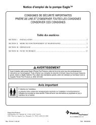
B. CLEAN & CLEAR ® PLUS TANK ASSY.<br />
1<br />
2<br />
3<br />
20<br />
4<br />
5<br />
7<br />
6<br />
8<br />
23<br />
9<br />
10<br />
13<br />
8, 17<br />
11<br />
12<br />
14<br />
22<br />
21<br />
16<br />
17<br />
18 19<br />
15<br />
P/N 178558 10 Rev. L 4-2-08
B. CLEAN & CLEAR ® PLUS TANK ASSY., cont'd.<br />
Replacement Parts<br />
Item No. Part No. Description<br />
1 190058 Gauge, pressure, ¼ in.<br />
2 98209800 High Flow manual air relief valve<br />
(HFMARV)<br />
3 98201200 Hose and retainer clips for<br />
HFMARV (Optional accy.)<br />
4 56636900 Spring, compression Ê<br />
4 178616 Spring, compression 1 1 1<br />
5 59071000 Manifold, top assy.<br />
5 170026 Manifold, top assy., 240 sq. ft.<br />
5 170027 Manifold, top assy., 320 & 520 sq. ft.<br />
6 R173572 <strong>Cartridge</strong> Element, 240 sq. ft., 4 req.<br />
6 R173573 <strong>Cartridge</strong> Element, 320 sq. ft., 4 req.<br />
6 R173574 <strong>Cartridge</strong> Element, 360 sq. ft., 4 req.<br />
6 R173575 <strong>Cartridge</strong> Element, 420 sq. ft., 4 req.<br />
aqua end caps <br />
6 R173576 <strong>Cartridge</strong> Element, 420 sq. ft., 4 req.<br />
6 R173577 <strong>Cartridge</strong> element, 520 sq. ft., 4 req.<br />
6 R173578 <strong>Cartridge</strong> element, 520 sq. ft., 4 req.<br />
7 170030 Air bleed tube assy., 240 sq. ft.<br />
7 55028500 Air bleed tube assy., 360, 420 sq. ft.<br />
7 170029 Air bleed tube assy., 320 sq. ft.<br />
7 170028 Air bleed tube assy., 420 sq. ft.<br />
7 55028400 Air bleed tube assy., 500 sq. ft.<br />
7 178583 Air bleed tube assy., 520 sq. ft.<br />
8 56626800 Manifold, bottom <br />
8 170035 Manifold, bottom/pipe assy., outlet <br />
8 170040 Manifold, bottom <br />
9 57000300 Gasket, bottom manifold <br />
10 39010200 O-ring, tank clamp (.470 O.D.)<br />
11 190003 Clamp kit, tension control<br />
Item No.Part No.<br />
Description<br />
12 195610 Washer, small I.D.<br />
12a 195611 Washer, large I.D.<br />
13 194997 Nut, machined <br />
13a 195612 Spring <br />
14 55035000 Baffle, bulkhead assy.<br />
14 190039 Baffle, bulkhead assy.<br />
15 86006900 O-ring, bulkhead, lower<br />
16 98960311 Bulkhead union, (set)<br />
16 271096 Bulkhead union, 1 ½ in. x 2 in.<br />
(set), white <br />
16 270004 Bulkhead union, 1 ½ in. x 2 in.<br />
(set), black <br />
17 59019200 Pipe assy., outlet <br />
17 170035 Pipe assy., outlet/manifold, bottom <br />
17 170036 Pipe assy., outlet <br />
18 51005000 O-ring for drain plug<br />
19 86202000 Plug, 1-1/2 in. drain with O-ring<br />
20 170023 Tank, lid assy., 240 sq. ft.<br />
20 170024 Tank, lid assy., 320 sq. ft.<br />
20 178552 Tank, lid assy., 360 sq. ft.<br />
20 178551 Tank, lid assy., 420 sq. ft.<br />
20 178581 Tank, lid assy., 420 sq. ft.<br />
20 178550 Tank, lid assy., 500 sq. ft.<br />
20 178582 Tank, lid assy., 520 sq. ft.<br />
21 178559 Tank, bottom assy.<br />
21 178578 Tank, bottom assy.<br />
22 86006900 O-ring, bulkhead, upper <br />
22 192320 O-ring, bulkhead, upper <br />
23 195339 Ring, back-up <br />
192019 Drain plug wrench<br />
010126 <strong>Filter</strong> lid opener tool<br />
Before 11/98<br />
After 11/98<br />
Between 11/98 thru 12/00<br />
After 12/00<br />
After 3/03<br />
After 10/04<br />
Between 11/98 thru 10/04<br />
Rev. L 4-2-08 11 P/N 178558
SAVE THESE INSTRUCTIONS<br />
© 2008 <strong>Pentair</strong> Water <strong>Pool</strong> and Spa, Inc. All rights reserved.<br />
1620 Hawkins Ave., Sanford, NC 27330 • (800) 831-7133 • (919) 566-8000<br />
10951 West Los Angeles Ave., Moorpark, CA 93021 • (800) 831-7133 • (805) 553-5000<br />
This document is subject to change without notice.<br />
Trademarks and Disclaimers: <strong>Pentair</strong> <strong>Pool</strong> Products ® , Because reliability matters most ® , <strong>Clean</strong> & <strong>Clear</strong> ® , and High Flow , are trademarks and/<br />
or registered trademarks of <strong>Pentair</strong> Water <strong>Pool</strong> and Spa, Inc. and/or its affiliated companies in the United States and/or other counties. Teflon ®<br />
is a registered trademark of E.I. Du Pont De Nemours and Company Corporation; Permatex ® is a registered trademark of Illinois Tool Works, Inc.;<br />
Baquacil ® and Baqua ® are registered trademarks of Arch UK Biocides Limited. Unless noted, names and brands of others that may be used in<br />
this document are not used to indicate an affiliation or endorsement between the proprietors of these names and brands and <strong>Pentair</strong> Water <strong>Pool</strong><br />
and Spa, Inc. Those names and brands may be the trademarks or registered trademarks of those parties or others.<br />
P/N 178558 12 Rev. L 4-2-08