Clarus 400/480 Harware and Software Manual - PerkinElmer
Clarus 400/480 Harware and Software Manual - PerkinElmer
Clarus 400/480 Harware and Software Manual - PerkinElmer

Create successful ePaper yourself
Turn your PDF publications into a flip-book with our unique Google optimized e-Paper software.
GAS CHROMATOGRAPHY<br />
CLARUS <strong>400</strong>/<strong>480</strong> GC<br />
Customer Hardware <strong>and</strong><br />
Service Guide
<strong>Clarus</strong> <strong>400</strong>/<strong>480</strong> GC Customer<br />
Hardware <strong>and</strong> Service Guide
Release History<br />
Part Number Release Publication Date<br />
09936811 C January 2010<br />
Any comments about the documentation for this product should be addressed to:<br />
User Assistance<br />
<strong>PerkinElmer</strong>, Inc.<br />
710 Bridgeport Avenue<br />
Shelton<br />
Connecticut 06484-4794<br />
U.S.A.<br />
Or emailed to: info@perkinelmer.com<br />
Notices<br />
The information contained in this document is subject to change without notice.<br />
Except as specifically set forth in its terms <strong>and</strong> conditions of sale, <strong>PerkinElmer</strong> makes no<br />
warranty of any kind with regard to this document, including, but not limited to, the implied<br />
warranties of merchantability <strong>and</strong> fitness for a particular purpose.<br />
<strong>PerkinElmer</strong> shall not be liable for errors contained herein for incidental consequential damages in<br />
connection with furnishing, performance or use of this material.<br />
Copyright Information<br />
This document contains proprietary information that is protected by copyright.<br />
All rights are reserved. No part of this publication may be reproduced in any form whatsoever or<br />
translated into any language without the prior, written permission of <strong>PerkinElmer</strong>, Inc.<br />
Copyright © 2010 <strong>PerkinElmer</strong>, Inc.<br />
Produced in the USA.<br />
Trademarks<br />
Registered names, trademarks, etc., used in this document, even when not specifically marked as such,<br />
are protected by law.<br />
<strong>PerkinElmer</strong> is a registered trademark of <strong>PerkinElmer</strong>, Inc.<br />
<strong>Clarus</strong> <strong>400</strong>/<strong>480</strong> GC is a trademark of <strong>PerkinElmer</strong>, Inc.<br />
e-ssentials is a trademark of <strong>PerkinElmer</strong>, Inc.
Table of Contents<br />
Introduction ................................................................................................... 5<br />
About This <strong>Manual</strong> ......................................................................................... 7<br />
<strong>Manual</strong> Conventions <strong>and</strong> Screen Abbreviations ............................................. 9<br />
Glossary of <strong>Clarus</strong> <strong>400</strong>/<strong>480</strong> GC Terms ......................................................... 11<br />
Glossary of Chromatographic Terms ............................................................ 13<br />
Symbols Located on the <strong>Clarus</strong> <strong>400</strong>/<strong>480</strong> GC ................................................ 16<br />
System Description ...................................................................................... 17<br />
Introduction ................................................................................................... 19<br />
Overview of the <strong>Clarus</strong> <strong>400</strong>/<strong>480</strong> GC ............................................................. 20<br />
About the Keyboard ...................................................................................... 22<br />
About the Screen ........................................................................................... 23<br />
Function Key Descriptions ........................................................................... 24<br />
Control Key Descriptions ............................................................................. 27<br />
Entry Keys .................................................................................................... 29<br />
Parameter Keys ............................................................................................. 31<br />
Before You Install a Column..................................................................... 33<br />
Column Installation Information ................................................................... 36<br />
Protecting Your Column ............................................................................... 38<br />
Turning the Oven Off <strong>and</strong> On ....................................................................... 39<br />
Turning Injector Heaters Off <strong>and</strong> On ............................................................ 40<br />
Turning Detector Heaters Off <strong>and</strong> On........................................................... 42<br />
Using the Built-in Stopwatch ........................................................................ 44<br />
Installing a Packed Column ....................................................................... 47<br />
Packed Column Injector Overview ............................................................... 49<br />
Installing A Capillary Column................................................................... 61<br />
Summary ....................................................................................................... 64<br />
Materials <strong>and</strong> Tools Required ....................................................................... 65<br />
Step A: Turn the Heaters Off: ....................................................................... 67<br />
Step B: Connect the Column to the Injector: ................................................ 68<br />
Step C: Set the Carrier Gas Using <strong>Manual</strong> Pneumatics ........................... 82<br />
Step D Leak Test All New Connections: ................................................ 85<br />
Step E: Condition the Column <strong>and</strong> the Mechanical Joint Between
the Pre-column <strong>and</strong> Column: 86<br />
Step G: Leak Test All New Connections: ................................................ 92<br />
Step H: Set up the Split Mode for a CAP Injector: .................................. 93<br />
Calculating a Capillary Column Split Ratio ................................................. 94<br />
Troubleshooting .......................................................................................... 95<br />
Messages Requiring <strong>PerkinElmer</strong> Service Assistance .................................. 98<br />
Background Calibration Error Messages ...................................................... 99<br />
Miscellaneous Error Messages.................................................................... 100<br />
Illegal Value Error Messages ...................................................................... 103<br />
GC Troubleshooting .................................................................................... 104<br />
Maintenance .............................................................................................. 107<br />
Autosampler Maintenance .......................................................................... 110<br />
Cleaning the Autosampler Tray .................................................................. 115<br />
Syringe Maintenance .................................................................................. 116<br />
Injector Maintenance .................................................................................. 118<br />
ECD Maintenance ....................................................................................... 134<br />
FID Maintenance ........................................................................................ 143<br />
NPD Maintenance ....................................................................................... 150<br />
TCD Maintenance ....................................................................................... 166<br />
Practical Hints ........................................................................................... 167<br />
Reversing TCD Polarity .............................................................................. 169<br />
Optimizing FID Performance...................................................................... 170<br />
Filtering Detector Output ............................................................................ 171<br />
Autozero Display Sensitivity ...................................................................... 172<br />
Attenuation vs. Detector Output ................................................................. 173<br />
Appendix U.S. Nuclear Regulations ...................................................... 175<br />
Nuclear Regulatory Commission Regulations ............................................ 184<br />
Index ........................................................................................................... 209
Introduction 1
<strong>Clarus</strong> <strong>400</strong>/<strong>480</strong> GC Customer Hardware <strong>and</strong> Service Guide<br />
About This <strong>Manual</strong><br />
The <strong>Clarus</strong> <strong>400</strong>/<strong>480</strong> GC Hardware <strong>and</strong> <strong>Software</strong> <strong>Manual</strong> is your complete detailed guide to<br />
setting up the <strong>Clarus</strong> <strong>400</strong>/<strong>480</strong> GC <strong>and</strong> integrated autosampler in preparation for running<br />
samples.<br />
This manual contains information <strong>and</strong> procedures for all of the available injectors <strong>and</strong><br />
detectors. To benefit the most from this manual, we recommend that you read all of the<br />
chapters in sequence <strong>and</strong> follow the procedures provided that apply to your specific injectors<br />
<strong>and</strong> detectors as closely as possible. In most cases, reading one chapter is a prerequisite for<br />
going on to the next.<br />
For detailed safety information please refer to the <strong>Clarus</strong> <strong>400</strong>/<strong>480</strong> GC Safety <strong>and</strong> Preparing<br />
Your Laboratory Guide (09936813).<br />
7
0BIntroduction<br />
The manual consists following chapters:<br />
Chapter 1<br />
Chapter 2<br />
Chapter 3<br />
Chapter 4<br />
Chapter 5<br />
Chapter 6<br />
Chapter 7<br />
Chapter 8<br />
Appendix<br />
Index<br />
Introducing the <strong>Clarus</strong> <strong>400</strong>/<strong>480</strong> GC provides an introduction to the<br />
manual, manual conventions, screen abbreviations, a glossary of <strong>Clarus</strong><br />
<strong>400</strong>/<strong>480</strong> GC terms <strong>and</strong> a glossary of chromatographic terms.<br />
System Description describes the <strong>Clarus</strong> <strong>400</strong>/<strong>480</strong> GC <strong>and</strong> its major<br />
features, including keyboard <strong>and</strong> display descriptions.<br />
Before You Install a Column contains general information regarding<br />
column installation <strong>and</strong> the basic procedures you ought to know in order<br />
to install a column.<br />
Installing a Packed Column contains procedures for connecting a<br />
packed column to the packed column injector <strong>and</strong> setting the carrier gas<br />
flow using manual pneumatics.<br />
Installing a Capillary Column contains procedures for connecting a<br />
capillary column to a Capillary Injector (CAP). It also describes how to<br />
set the gas flows using manual pneumatics.<br />
Troubleshooting lists the messages that may appear on the screen<br />
display, their causes <strong>and</strong> cures.<br />
Maintenance includes a variety of routine <strong>and</strong> preventive maintenance<br />
procedures for all injectors <strong>and</strong> detectors.<br />
Practical Hints contains useful information on attenuation, filtering<br />
detector output, <strong>and</strong> optimizing FID.<br />
A copy of Regulation 10 C.F.R. Section 31.5 of the U.S. Nuclear<br />
Regulatory Commission.<br />
8
<strong>Clarus</strong> <strong>400</strong>/<strong>480</strong> GC Customer Hardware <strong>and</strong> Service Guide<br />
<strong>Manual</strong> Conventions <strong>and</strong> Screen Abbreviations<br />
<strong>Manual</strong> Conventions<br />
Individual keys are displayed in the text by enclosing the name of the key in square brackets.<br />
For example, [Oven Prog], [Enter], [->Set], [Method], [System], [1], [8], etc.<br />
All temperatures are in degrees Celsius (C).<br />
Screen displays are presented throughout the text as a double-lined box:<br />
Method 1<br />
READY<br />
75°<br />
Screen Abbreviations<br />
Autosamp – autosampler<br />
AUX – Auxiliary zone<br />
Cap – capillary split/splitless injector<br />
Cmptr – computer<br />
Ctrl – syringe control parameters<br />
ECD – Electron Capture Detector<br />
Equil – equilibration<br />
Extrn – external<br />
FID – Flame Ionization Detector<br />
Gen – generate<br />
GSV – gas sampling valve<br />
Inj – injector<br />
Inj/Vial – injections per vial<br />
9
0BIntroduction<br />
Int – integrator<br />
kPa – kilopascals<br />
NPD – Nitrogen Phosphorus Detector<br />
OnCol – on column<br />
Ovn – oven<br />
Paus – pause<br />
Pkd – packed injector<br />
Pre – # of preinjection syringe washes<br />
Pres – pressure<br />
Prg – autosampler program<br />
Pri – priority sample vial<br />
Psi or psig – pounds per square inch (gauge)<br />
Rec – recorder<br />
Resm – resume<br />
Stpwtch – stopwatch<br />
TCD – Thermal Conductivity Detector<br />
10
<strong>Clarus</strong> <strong>400</strong>/<strong>480</strong> GC Customer Hardware <strong>and</strong> Service Guide<br />
Glossary of <strong>Clarus</strong> <strong>400</strong>/<strong>480</strong> GC Terms<br />
The glossary of <strong>Clarus</strong> <strong>400</strong>/<strong>480</strong> GC terms are divided into two types:<br />
• Autosampler Terms<br />
• Instrument-Specific Terms<br />
Autosampler Terms<br />
Term<br />
Washes<br />
Pre<br />
Post<br />
Pumps<br />
Mode<br />
Fast<br />
Normal<br />
Slow<br />
Solv<br />
Visc<br />
Description<br />
Washing the syringe.<br />
The number of prewashes of sample to prime the syringe (no<br />
pumping).<br />
The number of post injection syringe washes with a solvent.<br />
The number of times the syringe draws up sample <strong>and</strong><br />
evacuates it before acquiring the volume. This is done to<br />
eliminate bubbles.<br />
The style of injection.<br />
Fast speed of the syringe during sample injection. This is used<br />
to eliminate discrimination in the needle.<br />
Normal speed of the syringe during sample injection.<br />
Slow speed of the syringe during sample injection in order to<br />
inject directly into a wide-bore capillary column, in hot<br />
injection port.<br />
The number of solvent washes performed before the<br />
preinjection sample washes.<br />
The number of seconds the plunger pauses when drawing up a<br />
viscous sample into the syringe.<br />
11
0BIntroduction<br />
Instrument-Specific Terms<br />
Term<br />
Background<br />
compensation<br />
Ballistically<br />
Detector<br />
background<br />
Equilibration<br />
Isothermal method<br />
Method<br />
Negative-time<br />
event<br />
Parameter<br />
Pre-run<br />
Range<br />
Ready<br />
Run<br />
Sleep mode<br />
Timed Events<br />
Zone<br />
Description<br />
A routine that automatically subtracts a stored calibrated<br />
baseline profile from the signal generated during a GC run.<br />
Changing the oven temperature as quickly as possible to reach<br />
a set point.<br />
The detector output signal when no components are being<br />
eluted.<br />
The delay time after the method set points have been reached<br />
before the system becomes READY.<br />
A method in which the oven temperature remains constant<br />
throughout a GC run.<br />
A collection of parameters that control the GC.<br />
A timed event that you set to occur before the instrument<br />
becomes READY.<br />
An independent variable used to specify a condition to be met.<br />
The time after equilibration during which negative-time events<br />
are executed.<br />
For a Flame Ionization Detector, range means amplification of<br />
the detector output signal. For a Thermal Conductivity<br />
Detector, range means the bridge current.<br />
Indicates that all method parameters have reached their set<br />
points <strong>and</strong> that you can start your analysis.<br />
The time from sample injection to the end of the oven<br />
temperature program.<br />
The GC can be set to a predefined method for gas savings.<br />
Events that take place before or during a GC run as<br />
specified in a timed events table.<br />
A heated area in the GC oven, injector, or detector.<br />
12
<strong>Clarus</strong> <strong>400</strong>/<strong>480</strong> GC Customer Hardware <strong>and</strong> Service Guide<br />
Glossary of Chromatographic Terms *<br />
Adsorption – A process that occurs at the surface of a liquid or solid as a result of the<br />
attractive forces between the adsorbent <strong>and</strong> the solute. These forces may be physical or<br />
weakly chemical.<br />
Analysis – The complete investigation of a sample by gas chromatographic separation<br />
including identification of the sample components <strong>and</strong> quantitative measurements.<br />
Anode – The negatively charged electrode in any electrical circuit to which charged particles<br />
<strong>and</strong> ions are attracted.<br />
B<strong>and</strong> Broadening – A process that occurs in the GC whereby the peak width for a<br />
component increases the longer the component travels through the column.<br />
Baseline – The detector signal to a recorder or integrator when only the carrier gas is passing<br />
through the detector.<br />
Baseline drift – Any regular change occurring in the baseline signal from the detector,<br />
usually resulting from column temperature <strong>and</strong>/or gas flow changes.<br />
Blank run – A run without the sample being injected.<br />
Bleed – The evaporation of the stationary phase from a column.<br />
Capillary column (wall coated open tubular column) – A small-internal-diameter column<br />
whose inside wall is coated with a liquid phase.<br />
Carrier gas – The mobile phase of the separation system. An inert gas which transports the<br />
sample from the injector through the column to the detector. This gas is usually helium,<br />
hydrogen, or nitrogen.<br />
Column conditioning – A process for producing a stable column by heating the column with<br />
carrier gas flowing to remove volatile impurities from the stationary phase.<br />
Detectors – Hardware that responds to sample components producing an electrical signal that<br />
can be measured to quantitate the amount of each component present.<br />
* Reference: Denney, R.C. A Dictionary of Chromatography.<br />
13
0BIntroduction<br />
Flow rate – The mass flow of carrier gas or detector gas in milliliters per minute.<br />
Ghost peaks – Peaks that are not due to sample components, for example, peaks produced by<br />
carrier gas impurities, septum, or components from previous analyses.<br />
Injection port – The hardware through which the sample is introduced to the column by<br />
injection.<br />
Linearity – Quantitatively all detectors will produce a linear response with respect to solute<br />
concentration over a defined range, for example, the Linear Range.<br />
Liquid phase – The material in the column that causes the components to separate because of<br />
partitioning of the components between the mobile phase (carrier gas) <strong>and</strong> the stationary<br />
phase (liquid phase).<br />
Lowest limit of detection – The smallest amount of sample that can be detected by the<br />
detector being used. Usually defined as any signal that is as great as two times the noise<br />
level. Also referred to as Minimal Detectable Quantity (MDQ).<br />
Mobile phase – The gas which carries the solute (sample) along <strong>and</strong> over the column<br />
material. This carrier gas is inert <strong>and</strong> usually helium, nitrogen, or hydrogen.<br />
Noise – Background signal fluctuations arising from a detector response. This response is the<br />
result of the column installed, carrier gas purity, electronic components, etc. The<br />
response of any detector is defined by the signal-to-noise ratio.<br />
Partition Coefficient – The differential solubility of a substance in two different phases. In<br />
the case of gas–liquid chromatography, the sample components reach an equilibrium<br />
between the gas phase (mobile) <strong>and</strong> the liquid phase (stationary). Each component has a<br />
different partition coefficient thus causing separation in the column.<br />
Pressure programming – Pressure control through an independent four-step, three-ramp<br />
program for each carrier gas channel.<br />
Resolution – The degree of separation between two peaks.<br />
Retention time – The time interval from the point of injection to the appearance of the peak<br />
maximum, of a component’s signal.<br />
14
<strong>Clarus</strong> <strong>400</strong>/<strong>480</strong> GC Customer Hardware <strong>and</strong> Service Guide<br />
Septum – Silicone rubber material placed in the injection port through which the injection is<br />
made. When the needle is withdrawn, the silicone rubber reseals, thus not allowing any<br />
sample or carrier gas to escape.<br />
Stationary phase – The liquid or solid adsorbent portion of the column that retains<br />
components passing through the GC column.<br />
Syringes – Precision dispensing devices used to deliver sample to the GC. Liquid <strong>and</strong> gas<br />
syringes are available.<br />
Tailing – When a peak is not symmetrical or Gaussian shaped but the back end is broadened,<br />
it is said to be tailing.<br />
Temperature programming – A technique commonly used to increase the rate of elution of<br />
the components. After the sample is injected into the oven at a specific temperature, the<br />
temperature program increases the oven temperature to the prescribed temperature at a<br />
defined rate (in ºC/min).<br />
Unretained peak – A component that is not retained by the column. The time taken for an<br />
unretained sample to pass through the column is the same time as the time taken for the<br />
carrier gas to pass through.<br />
15
0BIntroduction<br />
Symbols Located on the <strong>Clarus</strong> <strong>400</strong>/<strong>480</strong> GC<br />
PNEUMATIC SYMBOL<br />
LEGEND<br />
CARRIER<br />
FLOW / PRESSURE<br />
SPLIT FLOW<br />
AIR<br />
HYDROGEN<br />
DETECTOR MAKE-UP/<br />
REFERENCE FLOW<br />
NPD FID TCD ECD<br />
NO CONNECTION<br />
16
System Description 2
Introduction<br />
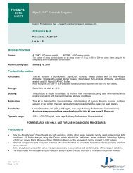
The <strong>Clarus</strong> <strong>400</strong>/<strong>480</strong> Gas Chromatograph is a dual-channel, temperature-programmable st<strong>and</strong>alone<br />
gas chromatograph (GC). It is available in many configurations, such as with or without,<br />
an autosampler <strong>and</strong> a variety of injector/detector combinations to provide you with total GC<br />
flexibility. The <strong>Clarus</strong> <strong>400</strong>/<strong>480</strong> GC is microprocessor controlled, where you enter the operating<br />
parameters from the color-coded keyboard <strong>and</strong> view the prompting text <strong>and</strong> monitor instrument<br />
functions on a large two-line vacuum fluorescence display.<br />
Figure 1. The <strong>Clarus</strong> <strong>400</strong>/<strong>480</strong> GC.
1BSystem Description<br />
Overview of the <strong>Clarus</strong> <strong>400</strong>/<strong>480</strong> GC<br />
Your <strong>Clarus</strong> <strong>400</strong>/<strong>480</strong> GC may have none, one, or two of the following detectors installed:<br />
‣ Flame Ionization (FID)<br />
‣<br />
Nitrogen Phosphorus (NPD)<br />
‣ Electron Capture (ECD)<br />
‣<br />
Thermal Conductivity (TCD)<br />
The FID, ECD, TCD, or the NPD, may be installed in either the front or the rear detector<br />
position.<br />
Each installed detector has one analog output which may be attached to either an integrator or<br />
recorder. Signals may be routed under instrument control.<br />
Either none, one, or two packed column injectors; none, one, or two capillary column<br />
injectors; or one of each injector type may be installed. Capillary column injectors consist of<br />
the conventional split/splitless injector (CAP).<br />
Up to two gas sampling valves may be installed.<br />
The <strong>Clarus</strong> <strong>400</strong>/<strong>480</strong> is a manual pneumatics instrument.<br />
The carrier gas <strong>and</strong> detector gas controls are built into the pneumatics control panel on the<br />
<strong>Clarus</strong> <strong>400</strong>/<strong>480</strong>. The carrier gas controls are used to set the flow for packed injectors <strong>and</strong> the<br />
pressure for CAP injectors. The detector gas controls are used to set the hydrogen <strong>and</strong> air for<br />
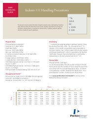
FID <strong>and</strong> NPD reference for TCD; <strong>and</strong> make-up gas for the ECD. Figure 2 is an example of a<br />
dual-channel pneumatics control panel with Channel 1 containing a capillary injector <strong>and</strong> a<br />
FID <strong>and</strong> Channel 2 containing a packed injector <strong>and</strong> an ECD.<br />
For each channel, the injector-pneumatic controls are on the left <strong>and</strong> the detector-pneumatic<br />
controls are on the right.<br />
20
<strong>Clarus</strong> <strong>400</strong>/<strong>480</strong> GC Customer Hardware <strong>and</strong> Service Guide<br />
Channel 1 Channel 2<br />
Figure 2. Example of a dual-channel pneumatics control panel in the <strong>Clarus</strong><br />
<strong>400</strong>/<strong>480</strong> GC.<br />
Channel 1 designates an injector/detector combination installed in the front position of the<br />
instrument, whereas Channel 2 designates a injector/detector combination installed in the rear<br />
position.<br />
21
1BSystem Description<br />
About the Keyboard<br />
The keyboard is your link to the software. The keyboard has 35 keys divided into the<br />
following groups:<br />
• Function keys<br />
• Parameter keys<br />
• Entry keys<br />
• Control keys<br />
NOTE: As you run this instrument you will see software functions on the display that are<br />
not supported by the <strong>Clarus</strong> <strong>400</strong>/<strong>480</strong> GC. Please ignore these functions <strong>and</strong> continue with<br />
your analysis.<br />
An audible short beep sounds every time a key is pressed. A long beep sounds when an error<br />
has been made. The key groups <strong>and</strong> their locations are illustrated in Figure 3.<br />
Function Keys<br />
Method<br />
System<br />
Auto<br />
Run<br />
Parameter Keys<br />
Oven<br />
Temp<br />
Time<br />
Rate<br />
7<br />
8<br />
9<br />
Entry Keys<br />
Inject<br />
Temp<br />
Carrier<br />
Gas<br />
Valve<br />
4<br />
5<br />
6<br />
Detect<br />
Temp<br />
Range<br />
Output<br />
on1 yes<br />
2 3<br />
Atten<br />
Auto<br />
Zero<br />
Events<br />
off 0 no<br />
Reset<br />
Oven<br />
Status<br />
Escape<br />
Delete Enter Set CE<br />
Control Keys<br />
Figure 3. The <strong>Clarus</strong> <strong>400</strong>/<strong>480</strong> GC keyboard.<br />
22
<strong>Clarus</strong> <strong>400</strong>/<strong>480</strong> GC Customer Hardware <strong>and</strong> Service Guide<br />
About the Screen<br />
The <strong>Clarus</strong> <strong>400</strong>/<strong>480</strong> GC screen is a 2-line by 20-character vacuum fluorescent display.<br />
Figure 4. Vacuum fluorescent screen.<br />
The screen displays status information, error messages, <strong>and</strong> interactive menus (method,<br />
system, configuration, autosampler, <strong>and</strong> background).<br />
23
1BSystem Description<br />
Function Key Descriptions<br />
The four function keys, [Method], [System], [Auto], <strong>and</strong> [Background], give access to the toplevel<br />
software menus. The [System] menu, in addition to presenting a number of system<br />
utility options, provides access to the Configuration Mode.<br />
Pressing a function key displays either a one-page menu or the first page of a two-page menu<br />
associated with that key.<br />
Method<br />
System<br />
Auto<br />
Run<br />
Oven<br />
Temp<br />
Time<br />
Rate<br />
7<br />
8<br />
9<br />
Inject<br />
Temp<br />
Carrier<br />
Gas<br />
Valve<br />
4<br />
5<br />
6<br />
Detect<br />
Temp<br />
Range<br />
Output<br />
on1 yes<br />
2 3<br />
Atten<br />
Auto<br />
Zero<br />
Events<br />
off 0 no<br />
Reset<br />
Oven<br />
Status<br />
Escape<br />
Delete Enter Set CE<br />
Figure 5. The Function keys.<br />
24
<strong>Clarus</strong> <strong>400</strong>/<strong>480</strong> GC Customer Hardware <strong>and</strong> Service Guide<br />
The Method Function Key<br />
Pressing [Method] displays the first page of the two-page Method Menu.<br />
Method 1<br />
Active<br />
¦ Setup Edit Copy ><br />
Method 1<br />
Active<br />
¦ Gen Delete Print ><br />
Method Menu, Page 1 Method Menu, Page 2<br />
The comm<strong>and</strong>s in the Method Menu provide utilities for managing <strong>and</strong> editing methods.<br />
Procedures for using these utilities are given in the <strong>Clarus</strong> <strong>400</strong>/<strong>480</strong> <strong>Software</strong> Guide (0993-<br />
6812), Controlling the <strong>Clarus</strong> <strong>400</strong>/<strong>480</strong> GC chapter. A brief description of these utilities<br />
follows.<br />
Comm<strong>and</strong><br />
Setup<br />
Edit<br />
Copy<br />
Gen<br />
Delete<br />
Prnt<br />
Description<br />
Sets up a Stored Method as the Active Method. This option is<br />
not available during a GC run or with active automation.<br />
Allows you to display <strong>and</strong> edit a Stored Method.<br />
Copies an existing method to another method number.<br />
Allows you to generate a new method from the default method.<br />
Allows you to delete one of the Stored Methods.<br />
Prints a method if a printer is attached.<br />
The System Function Key<br />
Pressing [System] displays the Page 1 of the two-page System Control menu.<br />
System Control<br />
¦ Config Lock ><br />
System Control<br />
¦ Stpwtch Extrn Prnt ><br />
System Control Menu, Page 1 System Control Menu, Page 2<br />
The comm<strong>and</strong>s in the System Control menu provide a number of system utilities.<br />
Procedures for using these utilities are given in <strong>Clarus</strong> <strong>400</strong>/<strong>480</strong> <strong>Software</strong> Guide (0993-6812),<br />
“System Utilities.” A brief description of these utilities follows.<br />
25
1BSystem Description<br />
Comm<strong>and</strong><br />
Config<br />
Lock<br />
Stpwtch<br />
Extrn<br />
Description<br />
Selecting this option puts the system into the Configuration Mode.<br />
The configuration menus allow you to specify configuration details<br />
for a variety of hardware options.<br />
Locks or unlocks the keyboard. For procedural details see Locking<br />
<strong>and</strong> Unlocking the Keyboard in Chapter 13, “System Utilities.”<br />
Accesses the stopwatch function. For procedural details see Chapter<br />
13, “System Utilities.”<br />
Used to set up an external computer or printer.<br />
The Auto(sampler) Function Key<br />
Pressing [Auto] displays the first page of the two-page Autosampler (A/S) menu.<br />
A/S Stopped<br />
¦ Prg Ctrl START ><br />
A/S Stopped<br />
¦ Park Clean Print ><br />
Autosampler Menu, Page 1 Autosampler Menu, Page 2<br />
The top line displays the autosampler’s status (for example, Stopped). The bottom line<br />
displays menu options.<br />
Autosampler details are too specialized <strong>and</strong> extensive to be described in this chapter. All<br />
details are provided in Chapter 11, “Controlling the Autosampler.”<br />
The Background Function Key<br />
Pressing [Background] displays the Background menu on the bottom line <strong>and</strong> the background<br />
status on the top line.<br />
Background 1 Off<br />
¦ Calibrate<br />
Detailed procedures for using this function are given in <strong>Clarus</strong> <strong>400</strong>/<strong>480</strong> <strong>Software</strong> Guide<br />
(0993-6812), “Background Compensation.”<br />
26
<strong>Clarus</strong> <strong>400</strong>/<strong>480</strong> GC Customer Hardware <strong>and</strong> Service Guide<br />
Control Key Descriptions<br />
Method<br />
System<br />
Auto<br />
Run<br />
Oven<br />
Temp<br />
Time<br />
Rate<br />
7<br />
8<br />
9<br />
Inject<br />
Temp<br />
Carrier<br />
Gas<br />
Valve<br />
4<br />
5<br />
6<br />
Detect<br />
Temp<br />
Range<br />
Output<br />
on1 yes<br />
2 3<br />
Atten<br />
Auto<br />
Zero<br />
Events<br />
off 0 no<br />
Reset<br />
Oven<br />
Status<br />
Escape<br />
Delete Enter Set CE<br />
Figure 6. The Control keys.<br />
The Run Key<br />
Press the [Run] key to start a GC run after manually injecting a sample, continue to run after<br />
an oven hold, or to initiate calibrating a background. Details for using [RUN] for the latter<br />
purpose are given in <strong>Clarus</strong> <strong>400</strong>/<strong>480</strong> <strong>Software</strong> Guide (09936812), “Background<br />
Compensation.”<br />
27
1BSystem Description<br />
The Reset Oven Key<br />
This key is used to reset the oven temperature during a run.<br />
Reset to oven Temp<br />
¦ 1 2 3<br />
During the execution of a temperature program, you can elect to heat the oven ballistically to<br />
a higher step by selecting the appropriate number from the menu.<br />
Select 1 to stop a run <strong>and</strong> reset the instrument to the initial method conditions. Additional<br />
details are given in <strong>Clarus</strong> <strong>400</strong>/<strong>480</strong> <strong>Software</strong> Guide (09936812), “Controlling the <strong>Clarus</strong><br />
<strong>400</strong>/<strong>480</strong> GC.”<br />
The Status Escape Key<br />
The [Status Escape] key is used to escape from various environments. The top level to which<br />
you can escape is the System Status screen.<br />
Method 1<br />
READY<br />
75º<br />
A screen similar to that above appears if you escape from the Method, System, Autosampler,<br />
or Background menus.<br />
If you press [Status Escape] a second time, the screen displays the Run End Time, as shown<br />
below.<br />
Method 1 READY<br />
END 13.0m<br />
In the case of a submenu, escape brings you up to a previous menu level.<br />
The Delete Key<br />
Use this key to delete a timed event or oven temperature program step.<br />
28
<strong>Clarus</strong> <strong>400</strong>/<strong>480</strong> GC Customer Hardware <strong>and</strong> Service Guide<br />
Entry Keys<br />
Method<br />
System<br />
Auto<br />
Run<br />
Oven<br />
Temp<br />
Time<br />
Rate<br />
7<br />
8<br />
9<br />
Inject<br />
Temp<br />
Carrier<br />
Gas<br />
Valve<br />
4<br />
5<br />
6<br />
Detect<br />
Temp<br />
Range<br />
Output<br />
on1 yes<br />
2 3<br />
Atten<br />
Auto<br />
Zero<br />
Events<br />
off 0 no<br />
Reset<br />
Oven<br />
Status<br />
Escape<br />
Delete Enter Set CE<br />
Figure 7. The Entry keys.<br />
All Entry keys, except for the [->Set] key, are similar to those on a h<strong>and</strong> calculator <strong>and</strong> are<br />
used to enter numeric data, clear an entry, etc.<br />
The [CE] key (Clear Entry) is used to clear a value before it is entered or to clear certain error<br />
messages from the screen.<br />
29
1BSystem Description<br />
The [On/Yes 1] <strong>and</strong> [Off/No 0] keys are multipurpose keys. In addition to using these keys<br />
for entering a numeric 1 or 0, they are used to enter "On" or "Off,” "Yes" or "No" in response<br />
to questions requiring these answers.<br />
The [->Set] key is used to move the screen cursor to a desired screen parameter or menu<br />
option for selection. How to use this key for this purpose is described in the next chapter.<br />
The[->Set] key is also used to activate the Autozero, ignite the FID flame, <strong>and</strong> actuate<br />
connected valves.<br />
30
<strong>Clarus</strong> <strong>400</strong>/<strong>480</strong> GC Customer Hardware <strong>and</strong> Service Guide<br />
Parameter Keys<br />
Method<br />
System<br />
Auto<br />
Run<br />
Oven<br />
Temp<br />
Time<br />
Rate<br />
7<br />
8<br />
9<br />
Inject<br />
Temp<br />
Carrier<br />
Gas<br />
Valve<br />
4<br />
5<br />
6<br />
Detect<br />
Temp<br />
Range<br />
Output<br />
on1 yes<br />
2 3<br />
Atten<br />
Auto<br />
Zero<br />
Events<br />
off 0 no<br />
Reset<br />
Oven<br />
Status<br />
Escape<br />
Delete Enter Set CE<br />
Figure 8. The Parameter keys.<br />
The Parameter keys are used to display operation or configuration parameters. Pressing a<br />
Parameter key when you not in the Configuration Mode displays the operating parameter<br />
associated with that key. Operating parameters are described in <strong>Clarus</strong> <strong>400</strong>/<strong>480</strong> <strong>Software</strong><br />
Guide (09936812), “Controlling the <strong>Clarus</strong> <strong>400</strong>/<strong>480</strong> GC chapter.” In the Configuration<br />
Mode, pressing a Parameter key displays the configuration of the hardware associated with<br />
that key.<br />
31
1BSystem Description<br />
32
<strong>Clarus</strong> <strong>400</strong>/<strong>480</strong> GC Customer Hardware <strong>and</strong> Service Guide<br />
Before You Install<br />
a Column<br />
3<br />
33
WARNING<br />
The moment the <strong>Clarus</strong> <strong>400</strong>/<strong>480</strong> GC is turned on, the oven, injector(s),<br />
<strong>and</strong> detector(s) begin to heat up rapidly. To avoid burns <strong>and</strong> injury<br />
while installing a column, all heaters should be turned off <strong>and</strong> their<br />
respective zones allowed to cool before touching the injector septum<br />
caps or any of the fittings inside the oven.<br />
This chapter contains general column installation information, <strong>and</strong> the following<br />
procedures:<br />
• Protecting your column.<br />
• Turning the oven off <strong>and</strong> on.<br />
• Turning injector heater(s) off <strong>and</strong> on.<br />
• Turning detector heater(s) off <strong>and</strong> on.<br />
• Using the built-in stopwatch.
2BBefore You Install<br />
a Column<br />
Column Installation Information<br />
Injector <strong>and</strong> Detector Fittings<br />
Columns are installed inside the oven. The injector fittings are on the left side <strong>and</strong> the<br />
detector fittings are on the right side of the oven ceiling. Figure 9 shows a capillary injector<br />
fitting in the front position <strong>and</strong> a packed injector fitting in the rear position.<br />
Before installing a column, make certain the oven is OFF (by opening<br />
the oven door), the oven fan has stopped, <strong>and</strong> the oven is cool.<br />
WARNING<br />
Figure 9. Injector <strong>and</strong> detector fittings.<br />
Column Hangers<br />
Capillary columns are supported on column hangers. The left <strong>and</strong> right sides of the oven<br />
walls each have two rectangular slots into which column hangers are inserted. The two rear<br />
slots are used to install a column hanger in the rear position. The two front slots are used to<br />
install a column in the front position.<br />
36
<strong>Clarus</strong> <strong>400</strong>/<strong>480</strong> GC Customer Hardware <strong>and</strong> Service Guide<br />
To install a column hanger, simply insert one end into the left slot <strong>and</strong> the other end into the<br />
right slot. If you are installing two capillary columns, install the rear hanger <strong>and</strong> the rear<br />
column before installing the front hanger <strong>and</strong> the front column.<br />
Figure 10. A column hanger installed in the oven rear position.<br />
37
2BBefore You Install<br />
a Column<br />
Protecting Your Column<br />
The <strong>Clarus</strong> <strong>400</strong>/<strong>480</strong> GC provides a means for protecting your column(s) from overheating. It<br />
does this by not allowing the oven to heat up beyond what we call the Oven Maximum<br />
Temperature Limit (OMTL), a value that you set in the Configuration Mode.<br />
You should set the OMTL equal to or less than the maximum permissible operating<br />
temperature recommended in the specifications for your column. If you are installing two<br />
columns, use the lower of the two permissible maximum operating temperatures.<br />
To protect the column, the OMTL value (that you enter) works in conjunction with the Oven<br />
Temperature specified in the Active Method. Should you (or someone else) attempt to set an<br />
Oven Temperature in the Active Method to a value greater than the OMTL, the system<br />
displays an error message <strong>and</strong> will not allow you to continue until an appropriate new oven<br />
temperature is set.<br />
The following screen shows an example of an error message:<br />
Illegal Oven Temp<br />
Range: xxx ---> yyy<br />
Where xxx <strong>and</strong> yyy are the permissible minimum <strong>and</strong> maximum oven temperatures<br />
respectively. You enter the OMTL in the Oven Maximum screen which is displayed from the<br />
Configuration Mode.<br />
To display the Oven Maximum screen:<br />
1. Press [System].<br />
The first page of the System Control Menu appears:<br />
System Control<br />
¦ Config Lock ><br />
2. Press [Enter] [Oven Prog].<br />
Oven Maximum Config<br />
Temp Limit ¦ 450°<br />
3. Type in the new OMTL (Oven Maximum Temperature Limit), then press [Enter].<br />
4. Press [Status Escape].<br />
38
<strong>Clarus</strong> <strong>400</strong>/<strong>480</strong> GC Customer Hardware <strong>and</strong> Service Guide<br />
Turning the Oven Off <strong>and</strong> On<br />
To turn the oven off:<br />
1. Open the oven door.<br />
The following message appears:<br />
OVEN DOOR OPEN<br />
Press CE to Continue<br />
The oven heater turns off.<br />
2. Press [CE].<br />
A status screen similar to the following appears:<br />
Method 1 OVN OFF<br />
Ovn 55°<br />
Notice that as the oven cools down, the actual temperature is continuously updated on the<br />
bottom line. When the oven temperature reaches 40 ºC, the oven fan turns off.<br />
3. Press [Status Escape].<br />
To turn the oven on:<br />
Simply close the oven door.<br />
39
2BBefore You Install<br />
a Column<br />
Turning Injector Heaters Off <strong>and</strong> On<br />
NOTE: The examples shown below assume that the <strong>Clarus</strong> <strong>400</strong>/<strong>480</strong> GC is in the READY state,<br />
position 1 (front) contains a capillary injector, <strong>and</strong> position 2 (rear) contains a packed<br />
injector.<br />
To turn the injector heaters Off:<br />
1. Press [Inject Prog].<br />
A screen similar to the following appears:<br />
Cap 1 150°<br />
Temperature ¦ 150°<br />
2. Press [Off/No 0].<br />
3. Press [Enter].<br />
The screen changes to:<br />
Cap 1 NOT RDY 149°<br />
Temperature ¦ Off<br />
Notice that the injector starts to cool.<br />
4. To turn off the second injector heater, display its screen <strong>and</strong> press<br />
[Inject Prog] again.<br />
Pkd 2 150°<br />
Temperature ¦ 150°<br />
5. Follow steps 2 <strong>and</strong> 3 above.<br />
6. Press [Status Escape].<br />
40
<strong>Clarus</strong> <strong>400</strong>/<strong>480</strong> GC Customer Hardware <strong>and</strong> Service Guide<br />
To turn the injector heaters on:<br />
1. Display the appropriate Injector Temperature Screen by pressing<br />
[Inject Prog] once or twice.<br />
Cap 1 30°<br />
Temperature ¦ Off<br />
2. Enter a temperature set point. For example type: [1] [5] [0], then press [Enter]. The<br />
screen changes to:<br />
Cap 1 NOT RDY 40°<br />
Temperature ¦ 150°<br />
3. Press [Status Escape].<br />
41
2BBefore You Install<br />
a Column<br />
Turning Detector Heaters Off <strong>and</strong> On<br />
NOTE: The examples shown below assume that the <strong>Clarus</strong> <strong>400</strong>/<strong>480</strong> GC is READY, an<br />
FID has been installed in position 1 (front), <strong>and</strong> an ECD is in position 2 (rear).<br />
To turn the detector heaters Off:<br />
1. Press [Detect Control].<br />
A screen similar to the following appears:<br />
FID 1 150°<br />
Temperature ¦ 150°<br />
2. Press [Off/No 0].<br />
The screen changes to:<br />
FID 1 NOT RDY 150°<br />
Temperature ¦ 0°<br />
Notice that the cursor is blinking, indicating a new value.<br />
42
<strong>Clarus</strong> <strong>400</strong>/<strong>480</strong> GC Customer Hardware <strong>and</strong> Service Guide<br />
3. Press [Enter]. The screen changes to:<br />
FID 1 NOT RDY 149°<br />
Temperature ¦ Off<br />
Notice that the detector starts to cool.<br />
4. To turn off the second detector heater, display its screen <strong>and</strong> press [Detect<br />
Control] again.<br />
ECD 2 150°<br />
Temperature ¦ 150°<br />
5. Follow steps 2 <strong>and</strong> 3 above.<br />
6. Press [Status Escape].<br />
To turn the detector heaters On:<br />
1. Display the appropriate Detector Temperature screen by pressing [Detect<br />
Control] once or twice.<br />
FID 1 NOT RDY 30°<br />
Temperature ¦ Off<br />
2. Enter a temperature set point.<br />
For example, type: [1] [5] [0], then press [Enter]. The screen changes to:<br />
FID 1 NOT RDY 40°<br />
Temperature ¦ 150°<br />
3. Press [Status Escape].<br />
43
2BBefore You Install<br />
a Column<br />
Using the Built-in Stopwatch<br />
To measure flows, use the stopwatch function with a soap bubble flowmeter. The following<br />
example shows how to measure flows using the built-in stopwatch.<br />
1. Press [System].<br />
The first page of the System Control menu appears:<br />
System Control<br />
¦ Config Lock ><br />
2. Press [System] again.<br />
The second page of the System Control menu appears:<br />
System Control<br />
¦ Stpwtch Extrn Print ><br />
3. Press [Enter].<br />
The Stopwatch screen appears:<br />
Stopwatch<br />
Flow<br />
0.00 m Vol ¦ 1<br />
4. Enter the volume of the flowmeter you are using.<br />
For example, change the default to 10 mL by typing [1] [0], then pressing [Enter].<br />
The screen changes to:<br />
Stopwatch<br />
Flow<br />
0.00 m Vol ¦ 10<br />
Start the Stopwatch<br />
5. When the bubble reaches the first graduation mark, Press [Enter]. This starts the<br />
timer.<br />
44
<strong>Clarus</strong> <strong>400</strong>/<strong>480</strong> GC Customer Hardware <strong>and</strong> Service Guide<br />
The elapsed time <strong>and</strong> calculated flow appear on the screen <strong>and</strong> are continuously<br />
updated.<br />
Stopwatch Flow 20<br />
0.50 m Vol ¦ 10<br />
Stop the Stopwatch<br />
6. When the bubble reaches the second graduation mark, press [Enter].<br />
The system freezes, calculates, <strong>and</strong> displays the flow in mL/min as of that point in<br />
time.<br />
Stopwatch Flow 4.0<br />
2.50 m Vol ¦ 10<br />
Reset the Stopwatch<br />
7. Press [CE].<br />
8. Press [Status Escape].<br />
45
2BBefore You Install<br />
a Column<br />
46
<strong>Clarus</strong> <strong>400</strong>/<strong>480</strong> GC Customer Hardware <strong>and</strong> Service Guide<br />
Installing a Packed<br />
Column<br />
4<br />
47
<strong>Clarus</strong> <strong>400</strong>/<strong>480</strong> GC Customer Hardware <strong>and</strong> Service Guide<br />
Packed Column Injector Overview<br />
The packed column injector consists of a septum cap, needle guide, quartz injector liner, <strong>and</strong><br />
the injector body. This injector is used with 1/8-inch or 1/4-inch glass or metal packed<br />
columns. In addition, by installing the 530 Micron Wide-Bore Adapter Kit (Part No<br />
N6120001) you can convert the injector to accept wide-bore capillary columns.<br />
Septum (P/N N6621028)<br />
Needle Guide<br />
Quartz Liner<br />
(P/N N6121003)<br />
Gas In<br />
Figure 11. Packed Column Injector.<br />
49
3BInstalling a Packed Column<br />
About the Wide-Bore Adapter<br />
If you are operating in the off-column mode at above optimum flow rates (>10 mL/min), you<br />
may not need to install the wide-bore quartz injector liner. Depending on your sample or<br />
solvent, the solvent profile (tail) may be acceptable for your application with the st<strong>and</strong>ard<br />
liner (the illustration at the left in Figure 11) <strong>and</strong> the addition of the adapter fitting (Part No<br />
N6100083). However, if the solvent profile is not acceptable, install the wide-bore quartz<br />
injector liner.<br />
The off-column or on-column flash vaporization mode of operation is determined by the<br />
position of the hourglass portion of the wide-bore quartz injector liner in the packed column<br />
injector. When installed correctly, this liner produces improved solvent profiles, especially at<br />
optimum flow rates. For complete installation instructions, refer to the Installation<br />
Instructions: 530 Micron Wide-Bore Adapter Kit for the AutoSystem GC <strong>and</strong> <strong>Clarus</strong> GC (Part<br />
No 09938661).<br />
Insert the wide-bore quartz injector liner (Part No N6121003) into the packed column injector<br />
with the hourglass portion in the correct position for your desired mode of operation. Figure<br />
11 shows a cross section of a packed column injector containing a st<strong>and</strong>ard liner <strong>and</strong> a cross<br />
section of a packed column injector containing a wide-bore quartz injector liner installed in<br />
the off-column position <strong>and</strong> the on-column position.<br />
For off-column flash vaporization (hourglass end first):<br />
To avoid contaminating the quartz wool, wear vinyl, powder-free disposable gloves (the same<br />
type used to perform maintenance on TurboMass). Take a small piece of quartz wool <strong>and</strong><br />
twist it into an elongated shape so that you can insert it into the liner. Then using a 1/16-inch<br />
rod (Part No N610T100), push the quartz wool into the liner. Loosely pack some quartz wool<br />
in the top portion of the liner to wipe the syringe needle upon injection. Insert the wide-bore<br />
quartz injector liner into the packed column injector with the hourglass end first.<br />
Or<br />
For on-column flash vaporization (hourglass end last):<br />
Insert the wide-bore quartz injector liner into the packed column injector with the hourglass<br />
end of the liner last. Do not pack the wide-bore quartz injector liner with silanized quartz<br />
wool. You must use a 0.47-mm O.D. syringe in this mode.<br />
If you are using the autosampler, install a 0.47-mm O.D. syringe (P/N N6101380) <strong>and</strong> use the<br />
“SLOW" injection mode.<br />
50
<strong>Clarus</strong> <strong>400</strong>/<strong>480</strong> GC Customer Hardware <strong>and</strong> Service Guide<br />
St<strong>and</strong>ard Packed<br />
Column<br />
Off-Column<br />
Position<br />
On-Column<br />
Position<br />
Hourglass<br />
St<strong>and</strong>ard<br />
Liner<br />
Wide-Bore<br />
Glass<br />
Injector<br />
Liner<br />
Wide-Bore<br />
Glass<br />
Injector<br />
Liner<br />
Silanized<br />
Glass Wool<br />
Silanized<br />
Glass Wool<br />
Hourglass<br />
1 5/8-inches Adapter<br />
Fitting<br />
Adapter<br />
Fitting<br />
Adapter<br />
Fitting<br />
Mark<br />
530 Micron<br />
Wide-Bore<br />
Column<br />
530 Micron<br />
Wide-Bore<br />
Column<br />
Figure 12. Cross sections of three packed injector configurations with a wide-bore<br />
column.<br />
530 Micron<br />
Wide-Bore<br />
Column<br />
51
3BInstalling a Packed Column<br />
Step 1: Turn off the Heaters<br />
WARNING<br />
The moment the <strong>Clarus</strong> <strong>400</strong>/<strong>480</strong> GC is turned on, the oven, injector(s),<br />
<strong>and</strong> detector(s) begin to heat up rapidly. To avoid burns <strong>and</strong> injury<br />
while installing a column, all heaters should be turned off <strong>and</strong> their<br />
respective zones allowed to cool before touching the injector septum<br />
caps or any of the fittings inside the oven.<br />
NOTE: See the <strong>Clarus</strong> <strong>400</strong>/<strong>480</strong> GC <strong>Software</strong> Guide for detailed procedures for turning heaters off<br />
<strong>and</strong> on.<br />
NOTE: It is recommended that you remove the injector liner shipped with the packed injector <strong>and</strong><br />
pack it with a small amount of silanized glass wool before performing analyses. Please refer<br />
to the Maintenance chapter later in this manual.<br />
Step 2: Set the Carrier Gas Flow<br />
The following two procedures describe how to set the carrier gas flow for manual pneumatics<br />
modules:<br />
• Setting the Carrier Gas Flow Using the Optional Flow Readout.<br />
• Setting the Carrier Gas Flow Using a Soap Bubble or Electronic Flowmeter.<br />
Setting the Carrier Gas Flow Using the Optional Flow Readout<br />
1. Turn on the carrier gas at the tank.<br />
2. Adjust the line pressure to 90 psig (or 620 kPa or 6.2 bar).<br />
3. Press [Carrier Prog] until the appropriate screen appears.<br />
Flow 1 30<br />
Set<br />
¦ 30mL/min<br />
4. Type the desired flow setpoint value <strong>and</strong> press [Enter].<br />
52
<strong>Clarus</strong> <strong>400</strong>/<strong>480</strong> GC Customer Hardware <strong>and</strong> Service Guide<br />
5. Adjust the flow by turning the flow control knob (see below) counterclockwise to<br />
increase the flow, clockwise to decrease the flow, until the actual flow displayed<br />
equals the set point value.<br />
HEAD PRESSURE<br />
Flow<br />
Control<br />
Knob<br />
CARRIER FLOW<br />
Figure 13. Flow Control Knob.<br />
Setting the Carrier Gas Flow Using a Soap Bubble or Electronic<br />
Flowmeter<br />
The procedure below assumes that you know how to measure carrier gas flow using a soap<br />
bubble or electronic flowmeter <strong>and</strong> the built-in stopwatch. If you need instructions, please<br />
read “Using Tools,” in the <strong>Clarus</strong> <strong>400</strong>/<strong>480</strong> GC <strong>Software</strong> Guide (09936812) before<br />
proceeding.<br />
1. Locate the packed injector fitting inside the oven.<br />
53
3BInstalling a Packed Column<br />
Packed Injector Fitting<br />
Figure 14. A packed injector fitting.<br />
6. Attach a soap bubble flowmeter to the packed injector fitting.<br />
7. Turn on the carrier gas at the tank <strong>and</strong> adjust the line pressure to 90 psig.<br />
8. Press [System] [System] [Enter] to display the stopwatch screen.<br />
9. Start the carrier gas flowing by turning the flow controller knob counterclockwise.<br />
10. Measure the flow.<br />
NOTE: For best accuracy, use a soap bubble flowmeter volume or electronic flowmeter that gives a<br />
reading of at least 30 seconds.<br />
11. Adjust the flow to the desired set point by repeatedly measuring the flow <strong>and</strong> turning the<br />
flow controller knob counterclockwise to increase the flow, clockwise to decrease the<br />
flow, until the desired flow is obtained.<br />
12. Disconnect the soap bubble flowmeter before proceeding to the next step.<br />
54
<strong>Clarus</strong> <strong>400</strong>/<strong>480</strong> GC Customer Hardware <strong>and</strong> Service Guide<br />
Step 3: Connect One End of the Column to the Packed<br />
Injector<br />
NOTE: If you are installing a 1/4-inch column, attach a 1/8-inch to 1/4-inch adapter to the packed<br />
injector fitting before continuing. Finger tighten the adapter, then while holding the packed<br />
injector fitting steady with a 7/16-inch wrench, tighten the adapter with a 9/16-inch wrench.<br />
1. Insert one end of the column into the packed injector fitting until it bottoms, then<br />
finger tighten the column nut onto the packed injector fitting (see the following<br />
figure).<br />
Figure 15. Packed column connected to a packed injector fitting.<br />
2. While holding the packed injector fitting with one 7/16-inch wrench, tighten the<br />
column nut an additional 1/8 to 1/4 turn with the other wrench.<br />
CAUTION<br />
Do not overtighten column nuts. Overtightening causes permanent<br />
damage to the fittings.<br />
55
3BInstalling a Packed Column<br />
Step 4: Leak Test<br />
Test the connection to the packed injector fitting for leaks using a 50/50 mixture of<br />
isopropanol/water or an electronic leak detector. To avoid contaminating the system, DO<br />
NOT use a soap solution for leak testing. Tighten all leaking connections.<br />
Step 5: Condition the Column<br />
This section contains a suggested temperature program for conditioning a column. The<br />
program starts off by holding the oven temperature at a medium value for 10 minutes,<br />
gradually increasing the oven temperature at a fixed rate (5 ºC/min) to the column operating<br />
temperature, then holding that temperature overnight with the carrier gas flowing.<br />
CAUTION<br />
The temperatures shown in the following examples should only be<br />
used as guidelines. Please refer to the column manufacturer's<br />
operating instructions for specific temperature recommendations.<br />
To condition the column:<br />
1. Close the oven door, then press [Oven Prog].<br />
The Oven Temperature screen appears.<br />
Oven NOT RDY 30°<br />
TEMP 1 ¦ 75°<br />
2. Enter an oven temperature set point of 50, then press [Enter].<br />
The Oven Time screen appears:<br />
Oven NOT RDY 0.0m<br />
TIME 1 ¦ 999.9m<br />
3. Enter a (Hold) TIME of 10, then press [Enter].<br />
The Oven Rate screen appears:<br />
Oven NOT RDY 30°<br />
RATE 1<br />
¦ End<br />
4. To add another program step, enter a RATE of 5 (ºC/min).<br />
56
<strong>Clarus</strong> <strong>400</strong>/<strong>480</strong> GC Customer Hardware <strong>and</strong> Service Guide<br />
A screen similar to the following appears:<br />
Oven NOT RDY 40°<br />
TEMP 2 ¦ 50°<br />
5. For TEMP 2, enter a set point 25 ºC to 50 ºC above your planned analytical operating<br />
temperature.<br />
For example, enter a set point of 150.<br />
Oven NOT RDY 50°<br />
TEMP 2 ¦ 150°<br />
CAUTION<br />
To avoid damaging the column, do not enter a temperature higher<br />
than the maximum operating temperature specified by the column<br />
manufacturer.<br />
6. Press [Enter]. The next screen is:<br />
Oven 0.0m<br />
TIME 2 ¦ 999.9m<br />
7. Press [Enter]. The next screen is:<br />
Oven<br />
RATE 2<br />
NOT RDY<br />
¦ End<br />
8. Set an Injection Temperature about 50 ºC higher than the TEMP 2 setting.<br />
9. Turn Detector Temperature off. Press [RUN] <strong>and</strong> allow the system to run overnight.<br />
10. The next morning press [Reset Oven].<br />
A menu similar to the following appears:<br />
Reset to Oven Temp<br />
¦ 1 2<br />
57
3BInstalling a Packed Column<br />
11. Press [Enter]. This resets the oven temperature set point to that specified for TEMP 1 at<br />
the beginning of the temperature program.<br />
12. Open the oven door, then press [CE].<br />
Allow the oven to cool until the oven fan goes off. This occurs when the oven cools<br />
down to 40 ºC.<br />
NOTE: Condition a new column before using it in an analysis. Once it is conditioned, you will not<br />
need to recondition it.<br />
Step 6: Attach the Other End of the Column to the Detector<br />
1. Insert the free end of the column into the detector fitting, then finger tighten the<br />
column nut onto the detector fitting.<br />
Figure 16. Packed column attached to the rear detector fitting.<br />
2. While holding the detector fitting with one of the 7/16-inch wrenches, tighten the<br />
column nut an additional 1/8 to 1/4 turn with the other wrench.<br />
58
<strong>Clarus</strong> <strong>400</strong>/<strong>480</strong> GC Customer Hardware <strong>and</strong> Service Guide<br />
CAUTION<br />
Make certain that no part of the column touches the bottom or sides<br />
of the oven once it is installed.<br />
NOTE: If you are installing a 1/4-inch column, attach a 1/8-inch to 1/4-inch adapter to the detector<br />
fitting before continuing. Finger tighten the adapter, then while holding the detector fitting<br />
steady with a 7/16-inch wrench, tighten the adapter with a 9/16-inch wrench.<br />
Step 7: Leak Test the Column/Detector Connection<br />
The following procedures describe leak testing the column to detector connections.<br />
With the carrier gas still flowing from the overnight conditioning, test the column/detector<br />
connection for leaks using a 50/50 mixture of isopropanol/water or use an electronic leak<br />
detector. To prevent contaminating the system, DO NOT use a soap solution for leak testing.<br />
Tighten the connection if a leak is found.<br />
Set up the detector to be used with this column (see The <strong>Clarus</strong> <strong>400</strong>/<strong>480</strong> GC <strong>Software</strong> Guide,<br />
Active Method chapter for information on setting up detectors).<br />
59
Installing A<br />
Capillary Column<br />
5
<strong>Clarus</strong> <strong>400</strong>/<strong>480</strong> GC Customer Hardware <strong>and</strong> Service Guide<br />
This chapter describes how to install a capillary column in the Capillary Split/Splitless (CAP)<br />
The information in this chapter is presented as one sequential procedure (Steps A through I)<br />
for all CAP injector with the following procedural steps:<br />
• Setting carrier gas flow using manual pneumatics<br />
• Leak testing<br />
• Conditioning the column<br />
• Attaching the column to the detector <strong>and</strong> leak checking<br />
NOTE: If you are analyzing reactive compounds, appropriately deactivate injector liners <strong>and</strong> wool<br />
for your sample type.<br />
CAUTION<br />
The CAP injector uses a 1/16-inch fitting for the column connection.<br />
This fitting is fragile. To preserve the integrity of the fitting,<br />
carefully connect the column nut to prevent cross-threading the<br />
fitting <strong>and</strong>/or overtightening the nut on the fitting. You can also<br />
preserve the integrity of the fitting by allowing the injector to cool<br />
before connecting a nut.<br />
63
4BInstalling A Capillary Column<br />
Summary<br />
The following steps summarize how to install a capillary column <strong>and</strong> get it ready for use:<br />
A. Turn the heaters off.<br />
B. Connect the column to the Split/Splitless (CAP) injector.<br />
C. Set the carrier gas to the proper pressure (Set the pressure for the CAP using the<br />
optional flow readout or a flowmeter.)<br />
D. Leak test all new connections.<br />
E. Condition the column (to the manufacturers specifications) <strong>and</strong> the mechanical joint<br />
between the column <strong>and</strong> pre-column.<br />
F. Connect the column to the detector.<br />
G. Leak test all new connections.<br />
64
<strong>Clarus</strong> <strong>400</strong>/<strong>480</strong> GC Customer Hardware <strong>and</strong> Service Guide<br />
Materials <strong>and</strong> Tools Required<br />
• 1/8-inch x 1.0-mm graphite ferrules (P/N 09903394) for 0.53-mm i.d. columns<br />
• 1/16-inch x 0.8-mm graphite ferrules (Part No 09920141) 1 for 0.53-mm i.d. columns<br />
• Two 7/16-inch open end wrenches<br />
• Two 1/4-inch open end wrenches<br />
• One 1/8-inch graphite ferrule (Part No 09903981) 1 for 0.32/0.25-mm i.d. columns<br />
• One 1/8-inch column nut (Part No 09903453)<br />
• One 1/16-inch graphite ferrule (Part No 09903700) 1 for 0.32/0.25-mm i.d. columns<br />
• One 1/16-inch column nut (Part No 09903392) 1<br />
• One screwdriver (P/N 0990-7273) 1<br />
• Deactivated 0.53-mm i.d. fused silica (P/N N6101724)<br />
• Fused-silica universal connector (P/N N9302149)<br />
• Capillary column of your choice<br />
• White-out or felt-tip marker<br />
• Scribe for cutting columns (P/N N9301376)<br />
(Pointed scribes are not recommended.)<br />
• Leak-test solution or electronic leak tester<br />
1 Shipped in the <strong>Clarus</strong> <strong>400</strong>/<strong>480</strong> GC Shipping Kit.<br />
65
4BInstalling A Capillary Column<br />
1/8-inch Column Nut<br />
(P/N 09903453)<br />
1/8-inch Graphite/Vespel Ferrule<br />
(P/N 09903981)<br />
1/16-inch Graphite/Vespel Ferrule<br />
(P/N 09903700)<br />
1/16-inch Column Nut<br />
(P/N 09903392)<br />
Figure 17. Examples of required fittings.<br />
66
<strong>Clarus</strong> <strong>400</strong>/<strong>480</strong> GC Customer Hardware <strong>and</strong> Service Guide<br />
Step A: Turn the Heaters Off:<br />
CAUTION<br />
The moment the <strong>Clarus</strong> <strong>400</strong>/<strong>480</strong> GC is turned on, the oven,<br />
injector(s), <strong>and</strong> detector(s) begin to heat up rapidly. To avoid<br />
injury while installing a column, all heaters should be turned off<br />
<strong>and</strong> their respective zones allowed too cool before touching the<br />
injector septum caps or any of the fittings inside the oven.<br />
CAUTION<br />
Before you install a column, follow the detailed procedures for<br />
turning heaters off <strong>and</strong> on, in Chapter 3 of this manual “Before<br />
You Install a Column.” If you have not read this chapter, please do<br />
so before proceeding<br />
67
4BInstalling A Capillary Column<br />
Step B: Connect the Column to the Injector:<br />
This step contains a procedure that describes how to connect a column to Column to the<br />
Split/Splitless (CAP) injector:<br />
Step B:<br />
Connect the Column to the Split/Splitless (CAP)<br />
Injector<br />
Overview<br />
The Split/Splitless injector (CAP) consists of a septum purge assembly <strong>and</strong> the injector body.<br />
Carrier gas enters the injector body at the point just above the O-ring <strong>and</strong> flows through the<br />
quartz liner past the column tip.<br />
68
<strong>Clarus</strong> <strong>400</strong>/<strong>480</strong> GC Customer Hardware <strong>and</strong> Service Guide<br />
Septum (P/N N6621028)<br />
Septum Purge<br />
O-Ring<br />
(P/N N9302783)<br />
Carrier Gas In<br />
Split Vent<br />
Quartz Liner<br />
Spit Point<br />
(Column Tip)<br />
Capillary Column<br />
1/4-inch to<br />
1/16-inch<br />
Column Fitting<br />
Figure 18. Cutaway view of the Split/Splitless injector (CAP).<br />
About the Injector Liners<br />
The CAP injector uses the following two quartz liners:<br />
• Narrow-bore (2-mm i.d.) liner (P/N N6121002).<br />
• Wide-bore (4-mm i.d.) liner (P/N N6121001).<br />
69
4BInstalling A Capillary Column<br />
The narrow-bore liner is generally used for splitless injections <strong>and</strong> the wide-bore liner is<br />
generally used for split injections. Due to its small internal volume (0.3 mL), the amount of<br />
sample injected into the narrow-bore liner should be limited to about 0.5 µL. This prevents<br />
the solvent expansion upon injection from overfilling the liner with vapor.<br />
To wipe the syringe needle, we recommend packing a small amount of quartz wool in the top<br />
portion of all liner types or injection modes (for example, split or splitless). Each liner should<br />
be packed with the quartz wool as described later in this chapter.<br />
Splitless Injections<br />
In the splitless injection mode, the narrow-bore quartz liner is typically used without quartz<br />
wool. The narrow-bore decreases the sample residence time in the liner, making it useful for<br />
trace analysis with smaller sample volumes (0.5 µL or less). By closing the split vent, most of<br />
the sample mixture enters the column. Then, opening the split vent clears the inlet of residual<br />
solvent.<br />
For splitless injection volumes over 0.5 µL, the wide-bore liner with an internal volume of<br />
1.25 mL should be used. However, the amount of sample should be limited to a maximum of<br />
2 µL for hydrocarbon solvents <strong>and</strong> less than that for high-expansion solvents such as water or<br />
CH 2 Cl 2 . Refer to Table 1 for examples of gas volumes formed upon sample injection for<br />
selected solvents.<br />
If the wide-bore liner is used for splitless injection, the splitless sampling time (vent-on time)<br />
should be at least one minute or more. Also, lower initial oven temperatures may be required<br />
to produce good solute resolution in the first few minutes after the solvent peak. The widebore<br />
liner should be used with columns having an i.d. of 0.32 mm or greater.<br />
70
<strong>Clarus</strong> <strong>400</strong>/<strong>480</strong> GC Customer Hardware <strong>and</strong> Service Guide<br />
Table 1. Gas Volumes Formed Upon Sample Injection<br />
(Injector 250 °C, Inlet Pressure 10 psig)<br />
Solvent Volume Injected (µL) Gas Volume Generated (µL)<br />
Methylene Chloride 1 333<br />
2 571<br />
Methanol 1 475<br />
2 768<br />
Water 1 823<br />
Split Injections<br />
2 1166<br />
In the split injection mode, the wide-bore quartz liner is packed with quartz wool to ensure<br />
thorough mixing of the sample <strong>and</strong> carrier gas before they encounter the column tip. The split<br />
vent is open at the time of injection so that a fraction of the sample mixture enters the column<br />
while the remainder is routed out through the split vent.<br />
<strong>Manual</strong> ControlPneumatics<br />
The injector pneumatics consist of a manual pneumatics (flow control valves <strong>and</strong> pressure<br />
regulators) version.<br />
For manual pneumatics, the pneumatics consists of a pressure regulator with an inline<br />
pressure transducer for screen readout of the current pressure <strong>and</strong> a needle valve to control<br />
the split vent.<br />
CAUTION<br />
The CAP injector is shipped with the wide-bore liner installed without<br />
quartz wool packing. Before using the injector, remove the liner <strong>and</strong><br />
pack it with quartz wool. If you are using the injector in the splitless<br />
mode, you may want to install the narrow-bore liner.<br />
71
4BInstalling A Capillary Column<br />
Connecting a Column to the Cap Injector<br />
The following five steps describe how to connect a column to the CAP injector:<br />
Step 1. Remove the CAP injector liner.<br />
Step 2. Select an appropriate CAP injector liner.<br />
Step 3. Pack the CAP injector liner with quartz wool.<br />
Step 4. Reinstall the liner in the CAP injector.<br />
Step 5. Connect a column to the CAP injector.<br />
Step 1. Remove the CAP Injector Liner.<br />
To remove a CAP injector liner:<br />
1. Ensure that the injector heater has been turned off.<br />
Allow the injector to cool until it is slightly warm to the touch. Cooling the<br />
injector to too-low a temperature (less than 80 °C) will make it difficult to<br />
remove the injector liner.<br />
2. Remove the septum cap.<br />
Septum Cap<br />
(P/N N6100153)<br />
Figure 19. Removing the septum cap.<br />
72
<strong>Clarus</strong> <strong>400</strong>/<strong>480</strong> GC Customer Hardware <strong>and</strong> Service Guide<br />
3. Remove the injector cover.<br />
Injector<br />
Cover<br />
Figure 20. Removing the injector cover.<br />
4. Loosen the threaded collar by using the spanner (P/N N6101359) provided, then<br />
remove the threaded collar.<br />
Spanner<br />
(P/N N6101359)<br />
Figure 21. Loosening the threaded collar.<br />
5. Replace the septum cap on the injector.<br />
6. Pull the septum cap upwards to remove the septum purge assembly.<br />
73
4BInstalling A Capillary Column<br />
Figure 22. Removing the septum purge assembly.<br />
7. The carrier gas inlet line is coiled to allow you to pull the septum purge assembly over<br />
to the side <strong>and</strong> gain access to the liner.<br />
8. Ensure that the CAP injector liner is cool, then twist the CAP injector liner-removal<br />
tool (P/N 02506534, see Figure 24) onto the injector liner. Remove the injector liner by<br />
lifting it up <strong>and</strong> out of the injector.<br />
The CAP liner must be cool (no hotter than 100 °C) or the liner-removal tool will<br />
melt! The end of the CAP liner-removal tool may flare out with use. If this happens,<br />
cut off the flared end with a razor blade or scissors.<br />
Figure 23. CAP injector liner-removal tool (P/N 02506534).<br />
74
<strong>Clarus</strong> <strong>400</strong>/<strong>480</strong> GC Customer Hardware <strong>and</strong> Service Guide<br />
Figure 24. Removing a capillary injector liner.<br />
CAUTION<br />
If the O-ring adheres to the injector body, use a small screwdriver to loosen<br />
the O-ring so that you can remove the liner <strong>and</strong> O-ring. Be careful not to<br />
scratch the barrel where the O-ring seals. Discard this O-ring <strong>and</strong> install a<br />
new O-ring.<br />
NOTE: If the liner breaks inside the CAP injector, it can be removed by first removing the column.<br />
Then using a 9/16-inch wrench, remove the 1/4-inch injector fitting inside the oven. The liner<br />
should fall out. If the liner is stuck, you can push it out from the top or bottom.<br />
Step 2. Select an Appropriate CAP Injector Liner.<br />
Select the appropriate injector liner for your application. The following two injector liners are<br />
available for the CAP injector:<br />
• 4-mm i.d. <strong>and</strong> 6-mm o.d. CAP injector wide-bore liner (P/N N6121001)<br />
• 2-mm i.d. <strong>and</strong> 6-mm o.d. CAP injector narrow-bore liner (P/N N6121002)<br />
75
4BInstalling A Capillary Column<br />
The narrow-bore liner is generally used for a splitless injection, <strong>and</strong> the wide-bore liner is<br />
generally used for a split injection. Due to the small internal volume (0.3 mL) of the narrowbore<br />
liner, you can prevent overfilling the liner with vapor (caused by solvent expansion upon<br />
injection) by limiting the amount of sample injected to 0.5 µL.<br />
The wide-bore liner is used for splitless injection volumes over 0.5 µl since its internal<br />
volume is 1.25 mL. The sample size should be limited to a maximum of 2 µL for<br />
hydrocarbon solvents <strong>and</strong> less than that for high-expansion solvents, such as water or<br />
CH 2 Cl 2 . Refer to Table 6-1.<br />
If the wide-bore liner is used for splitless injection, the splitless sampling time (vent-on time)<br />
should be more than one minute. Also, lower initial oven temperatures may be required to<br />
give good resolution in the first few minutes after the solvent peak. The wide-bore liner<br />
should be used with columns having an i.d. of 0.32 mm or greater.<br />
Step 3. Pack the CAP Injector Liner with Quartz Wool.<br />
To wipe the syringe needle, we recommend packing a small amount of quartz wool (P/N<br />
6102354) in the top portion of the liner regardless of the liner type or injector mode used (for<br />
example, split or splitless). This packing assures that reproducible volumes are injected<br />
because it wipes the syringe needle every time the needle is inserted.<br />
Remove the liner <strong>and</strong> replace the quartz wool packing on a regular basis, particularly if your<br />
samples contain nonvolatile components that could build up on the wool. This could cause<br />
adsorption of peaks of interest, tailing, <strong>and</strong> loss of sensitivity. Remove the wool with a small<br />
hook on the end of a thin wire, or blow it out using compressed air.<br />
NOTE: To avoid contaminating the quartz wool when packing the injection liner, wear vinyl,<br />
powder-free, disposable.<br />
Packing CAP Injector Liner for Split Operation<br />
Take a small piece of quartz wool <strong>and</strong> twist it into an elongated shape so that you can insert it<br />
into the liner. Then using a 1/16-inch rod (P/N N610T100), push the quartz wool (P/N<br />
6102354) into the liner. Pack the wool tightly 2 from the dimple upwards (about one inch [2.5<br />
cm]). Loosely pack quartz wool in the top portion of the liner to wipe the syringe needle upon<br />
injection.<br />
2 The recovery of high molecular weight components (e.g., C40) may be improved if the liner is loosely packed.<br />
76
<strong>Clarus</strong> <strong>400</strong>/<strong>480</strong> GC Customer Hardware <strong>and</strong> Service Guide<br />
Packing a CAP Injector Liner for Splitless Operation<br />
Take a small piece of quartz wool <strong>and</strong> twist it into an elongated shape so that you can insert it<br />
into the liner. Then using a 1/16-inch rod (P/N N610T100), push the quartz wool (P/N<br />
6102354) into the liner. Pack a one-inch piece (2.5 cm) of quartz wool loosely below the top<br />
ground portion of the liner (see Figure 27). The sample is then injected into the wool, thereby<br />
preventing the delivery of sample beyond the column. The wool also wipes the syringe needle<br />
upon injection.<br />
SPLITLESS PACKING SPLIT PACKING<br />
O-Rings<br />
O-Ring<br />
Glass Wool<br />
Loosely<br />
Packed<br />
Glass Wool<br />
Loosely<br />
Packed<br />
Glass Wool<br />
Tightly Packed<br />
Dimple<br />
Dimple<br />
Wide Bore Liner<br />
(Part No. N6101052)<br />
Narrow Bore Liner<br />
(Part No. N6101744)<br />
Figure 25. CAP injector liners packed with quartz wool.<br />
Step 4. Reinstall the Liner in the CAP Injector.<br />
To reinstall the liner:<br />
1. Install a new O-ring near the ground portion of the liner.<br />
Wide Bore Liner<br />
(Part No. N6101052)<br />
77
4BInstalling A Capillary Column<br />
2. Insert the liner in the injector body.<br />
3. Place the septum purge assembly over the liner.<br />
4. Press the septum purge assembly down to correctly position the liner in the injector.<br />
5. Replace the threaded collar <strong>and</strong> tighten the assembly using the spanner (P/N<br />
N6101359).<br />
Step 5. Connect a Column to the CAP Injector.<br />
CAUTION<br />
This injector terminates in a 1/16-inch fitting. This fitting is fragile. To<br />
preserve the integrity of the fitting, carefully connect the nut to prevent<br />
cross-threading the fitting <strong>and</strong>/or overtightening the nut on the fitting. You<br />
can also preserve the integrity of the fitting by allowing the injector to<br />
cool before connecting a nut.<br />
To connect a column:<br />
1. Insert a 1/16-inch column nut (P/N 09903392) <strong>and</strong> 1/16-inch graphite ferrule (0.8<br />
mm i.d., P/N 09920141 or 0.5 mm i.d., P/N 09903700) over one end of the column as<br />
shown below:<br />
1/16-inch Column Nut<br />
(P/N 09903392)<br />
White-Out<br />
1/16-inch Graphite/Vespel Ferrule<br />
(P/N 09903700)<br />
Figure 26.<br />
Narrow-bore capillary column, nut, <strong>and</strong> ferrule on the injector end of a<br />
column.<br />
NOTE: Verify that the tapered end of the ferrule is facing towards the nut as shown above.<br />
78
<strong>Clarus</strong> <strong>400</strong>/<strong>480</strong> GC Customer Hardware <strong>and</strong> Service Guide<br />
2. Cut off about 1 cm (3/8 inch) from the column end using a wafer scribe (P/N<br />
N9301376, pkg. of 10 scribes). Break off the tubing at the score mark so that the<br />
break is clean <strong>and</strong> square. Examine the cut with a magnifying glass <strong>and</strong> compare it to<br />
the examples shown in the following figure:<br />
Good Cut<br />
Bad Cuts<br />
Figure 27. Example of a good cut <strong>and</strong> bad cuts.<br />
3. Position the column not on the column so that the back of the nut is 4.4 cm to 5.1 (1 ¾<br />
inches to 2 inches) from the end of the column.<br />
4. Using typewriter "white-out" or a felt-tipped pen, make a mark on the column just<br />
beyond the back edge of the column nut (see Figure 26).<br />
CAUTION<br />
To avoid contaminating the system, make certain that the nut <strong>and</strong><br />
ferrule do not contact the mark on the column.<br />
5. Locate the capillary injector fitting inside the oven.<br />
79
4BInstalling A Capillary Column<br />
Capilary<br />
Injector<br />
Fitting<br />
Figure 28. Capillary injector fitting inside the oven.<br />
6. Insert the column into the capillary injector fitting. Then h<strong>and</strong>-tighten the column nut onto<br />
the capillary injector fitting. Insert the column into the capillary injector fitting until the<br />
mark is aligned with the back of the nut.<br />
7. Using two 1/4-inch wrenches, tighten the column nut only until the column cannot be<br />
pulled out of the fitting.<br />
CAUTION<br />
Do not overtighten column nuts. Overtightening can cause<br />
damage to the ferrule <strong>and</strong>/or column.<br />
80
<strong>Clarus</strong> <strong>400</strong>/<strong>480</strong> GC Customer Hardware <strong>and</strong> Service Guide<br />
Figure 29. Capillary column attached to capillary injector fitting.<br />
81
4BInstalling A Capillary Column<br />
Step C: Set the Carrier Gas Using <strong>Manual</strong><br />
Pneumatics<br />
This step describes how to set the carrier gas for manual pneumatics modules. Refer to the<br />
procedure Setting the Carrier Gas Using <strong>Manual</strong> Pneumatics.<br />
This step includes procedures to set the carrier gas pressure for the split/splitless (CAP).<br />
Setting the Carrier Gas Pressure for the Split/Splitless Injector (CAP)<br />
Carrier gases for the split/splitless injector (CAP) are controlled by adjusting the pressure<br />
with the pressure control knob. The location <strong>and</strong> appearance of the pneumatic controls for a<br />
capillary injector are shown in the following figure.<br />
I 0<br />
SPLIT FLOW<br />
Pressure<br />
Control<br />
Knob<br />
CARRIER PRESSURE<br />
Figure 30.<br />
CAP pneumatic controls.<br />
To adjust the carrier gas pressure:<br />
1. Turn on the carrier gas at the tank. Adjust the line pressure to 90 psig (or 620 kPa or 6.2<br />
bar).<br />
2. Press [Carrier Prog].If a capillary injector is in position 1, the Pressure Readout appear.<br />
Pres 1 25.0<br />
Set<br />
¦ 25.0 Psi<br />
82
<strong>Clarus</strong> <strong>400</strong>/<strong>480</strong> GC Customer Hardware <strong>and</strong> Service Guide<br />
If the capillary injector is in position 2, press [Carrier Prog] again.<br />
NOTE: The Pressure Readout display is factory configured to display the actual pressure as psig. To<br />
display the actual pressure as kilopascals (kPa), refer to <strong>Clarus</strong> <strong>400</strong>/<strong>480</strong> GC <strong>Software</strong> Guide<br />
(09936812), “Initial Setup Procedures” chapter.<br />
3. Enter a pressure set point. (See Suggested Capillary Column Pressures below.)<br />
4. Turn the pressure control knob until the readout on the top line equals the set point.<br />
Suggested Capillary Column Pressures:<br />
The following tables are manual pneumatics of the <strong>Clarus</strong> <strong>400</strong>/<strong>480</strong> GC.<br />
Table 2. Calculated Pressure Drops (psig) for 10m Column 3<br />
Column I.D. (µm)<br />
_<br />
u 4 320 250 100<br />
10 1.0 2.4 10.0<br />
20<br />
30<br />
2.1<br />
3.1<br />
4.9<br />
7.3<br />
21.2<br />
31.8<br />
40 4.1 9.8 42.3<br />
60<br />
80<br />
6.2<br />
8.3<br />
14.6<br />
19.5<br />
63.5<br />
84.7<br />
Table 3. Calculated Pressure Drops (psig) for 25m Columns 4<br />
Column I.D. (µm)<br />
_<br />
u 5 320 250 100<br />
10 2.6 6.1 26.5<br />
20 5.2 12.2 52.9<br />
30<br />
40<br />
7.8<br />
10.3<br />
18.3<br />
24.4<br />
79.4<br />
-<br />
60<br />
80<br />
15.5<br />
20.7<br />
36.6<br />
48.8<br />
-<br />
-<br />
3 In psig, using helium as a carrier gas at 100 °C.<br />
4 Average linear velocity (cm/sec).<br />
83
4BInstalling A Capillary Column<br />
Table 4. Calculated Pressure Drops (psig) for 50m Columns 4<br />
Column I.D. (µm)<br />
_<br />
u 5 320 250 100<br />
10 5.2 12.2 52.9<br />
20<br />
30<br />
10.3<br />
15.5<br />
24.4<br />
36.6<br />
-<br />
-<br />
40 20.7 48.8 -<br />
60<br />
80<br />
31.0<br />
41.3<br />
73.2<br />
-<br />
-<br />
-<br />
84
<strong>Clarus</strong> <strong>400</strong>/<strong>480</strong> GC Customer Hardware <strong>and</strong> Service Guide<br />
Step D<br />
Leak Test All New Connections:<br />
<strong>Manual</strong> Pneumatics<br />
Test the connection to the capillary injector fitting for leaks using a 50/50 mixture of<br />
isopropanol/water or an electronic leak detector. To avoid contaminating the system, DO<br />
NOT use a soap solution for leak testing. Tighten all leaking connections.<br />
85
4BInstalling A Capillary Column<br />
Step E:<br />
Condition the Column <strong>and</strong> the Mechanical<br />
Joint Between the Pre-column <strong>and</strong> Column:<br />
This section contains a suggested temperature program for conditioning a column. The<br />
program starts off by holding the oven temperature at a medium value for 10 minutes,<br />
gradually increasing the oven temperature at a fixed rate (5 °C/min) to the column operating<br />
temperature, then holding that temperature overnight with the carrier gas flowing.<br />
CAUTION<br />
The temperatures shown in the examples which follow<br />
should be used as guidelines. Please refer to the column<br />
manufacturer's operating instructions for specific<br />
temperature recommendations.<br />
CAUTION<br />
To keep the injector clean, open the split vent to direct<br />
more gas through the injector.<br />
To condition the column:<br />
1. Close the oven door <strong>and</strong> press [Oven Prog].<br />
The Oven Temperature screen appears.<br />
Oven NOT RDY 30°<br />
TEMP 1 ¦ 75°<br />
2. Enter an oven temperature set point of 50 ºC <strong>and</strong> press [Enter].<br />
The Oven Time screen appears.<br />
Oven 0.0m<br />
TIME 1 ¦ 999.9m<br />
3. Enter a (Hold) TIME of 10 <strong>and</strong> press [Enter].<br />
86
<strong>Clarus</strong> <strong>400</strong>/<strong>480</strong> GC Customer Hardware <strong>and</strong> Service Guide<br />
The Oven Rate screen appears.<br />
Oven NOT RDY 30°<br />
RATE 1<br />
¦ End<br />
4. To add another program step, enter a RATE of 5(ºC/min).<br />
A screen similar to the following appears.<br />
Oven NOT RDY 40°<br />
TEMP 2 ¦ 50°<br />
5. For TEMP 2, enter a set point 25 to 50 ºC above your planned analytical operating<br />
temperature. For example, enter a set point of 200:<br />
Oven NOT RDY 50°<br />
TEMP 2 ¦ 200°<br />
CAUTION<br />
To avoid damaging the column, do not enter a<br />
temperature higher than the maximum recommended<br />
temperature specified by the column manufacturer.<br />
6. Press [Enter].<br />
The following screen appears:<br />
7. Press [Enter].<br />
Oven 0.0m<br />
TIME 2 ¦ 999.9m<br />
The following screen appears:<br />
Oven<br />
RATE 2<br />
NOT RDY<br />
¦ End<br />
8. Configure the injector for the oven mode. Refer to the <strong>Clarus</strong> <strong>400</strong>/<strong>480</strong> GC <strong>Software</strong> Guide<br />
(09936812), Initial Setup Procedures chapter.<br />
87
4BInstalling A Capillary Column<br />
9. Turn the Detector Temperature off.<br />
10. Press [RUN]. Allow the system to run overnight.<br />
11. In the morning, press [Reset Oven].<br />
12. A menu similar to the following appears:<br />
13. Press [Enter].<br />
Reset to Oven Temp<br />
¦ 1 2<br />
14. This resets the oven temperature set point to that specified for TEMP 1 at the beginning of<br />
the temperature program.<br />
15. Open the oven door, then press [CE].<br />
16. Allow the oven to cool until the oven fan turns off. This occurs when the oven cools down<br />
to 40ºC.<br />
88
<strong>Clarus</strong> <strong>400</strong>/<strong>480</strong> GC Customer Hardware <strong>and</strong> Service Guide<br />
Step F:<br />
Connect the Column to the Detector:<br />
1. Place the column over the hanger so that no part of the column touches the bottom or<br />
sides of the oven.<br />
2. Insert a 1/8-inch column nut <strong>and</strong> graphite ferrule over the free end of the column as<br />
shown below:<br />
White-Out<br />
1/8-inch Column Nut<br />
(P/N 0990-3453)<br />
1/8-inch Graphite/Vespel Ferrule<br />
(P/N 0990-3981)<br />
Figure 31. Nut <strong>and</strong> ferrule on the detector end of a narrow-bore capillary column.<br />
3. Cut about 1 cm (3/8 inch) from the column end using a wafer scribe<br />
(P/N N9301376, pkg. of 10 scribes) or other column cutting tool. Break off the tubing<br />
at the score mark so that the break is clean <strong>and</strong> square. Examine the cut with a<br />
magnifying glass <strong>and</strong> compare it to the following figure:<br />
Good Cut<br />
Bad Cuts<br />
Figure 32. Example of a good cut <strong>and</strong> bad cuts.<br />
4. Mark the column the following distances from the end using typewriter "white-out"<br />
or a felt-tipped pen:<br />
89
4BInstalling A Capillary Column<br />
Column<br />
Diameter<br />
Detector to which you are<br />
attaching the column<br />
Distance from back of<br />
nut<br />
≤0.53 mm i.d. FID 2.75 inches (70 mm)<br />
≤0.53 mm i.d. ECD 5 2.5 inches (64 mm)<br />
≤0.53 mm i.d. TCD 4 inches (103 mm)<br />
≤0.53 mm i.d. NPD 3 inches (77 mm)<br />
CAUTION<br />
To avoid contaminating the system, make certain that the<br />
nut <strong>and</strong> ferrule do not contact the mark on the column.<br />
5. Locate the detector fitting protruding from the right side of the oven roof.<br />
6. Insert the column into the detector fitting, keeping the mark just behind the column nut.<br />
7. While holding the column in position, h<strong>and</strong>-tighten the column nut.<br />
8. Hold the detector fitting steady with one of the 7/16-inch wrenches as you gradually tighten<br />
the column nut with the other wrench. Tighten the nut only until you cannot pull the<br />
column out of the nut. DO NOT OVERTIGHTEN THE NUT!<br />
5 A glass-lined receiver (P/N N600-0968) is available to reduce high background readings.<br />
For more details, see the Important on page 8-22.<br />
90
<strong>Clarus</strong> <strong>400</strong>/<strong>480</strong> GC Customer Hardware <strong>and</strong> Service Guide<br />
Detector<br />
Fitting<br />
Column<br />
Nut<br />
Figure 33.<br />
Capillary column connected to the detector fitting.<br />
CAUTION<br />
Make certain that no part of the column touches the walls<br />
or bottom of the oven.<br />
CAUTION<br />
Do not overtighten column nuts. Overtightening can cause<br />
damage to the ferrule <strong>and</strong>/or column.<br />
91
4BInstalling A Capillary Column<br />
Step G: Leak Test All New Connections:<br />
Test the detector connection for leaks using a 50/50 mixture of isopropanol/water or an<br />
electronic leak detector. To avoid contaminating the system, DO NOT use a soap solution for<br />
leak testing. Tighten all leaking connections.<br />
92
<strong>Clarus</strong> <strong>400</strong>/<strong>480</strong> GC Customer Hardware <strong>and</strong> Service Guide<br />
Step H: Set up the Split Mode for a CAP Injector:<br />
The Split Mode is used to analyze concentrated samples. In this mode only part of the sample<br />
enters the column; the remainder is split <strong>and</strong> vented through a charcoal filter to atmosphere.<br />
This step describes how to set the split mode for manual pneumatics modules. Refer to the<br />
procedure that describes your <strong>Clarus</strong> <strong>400</strong>/<strong>480</strong> GC manual pneumatics control..<br />
Step H: Setting the Split Mode Using <strong>Manual</strong> Pneumatics.<br />
NOTE: In the Split Mode, the split vent is always open.<br />
NOTE: The injector is shipped with an unpacked wide-bore injector liner installed. Remove the liner<br />
<strong>and</strong> pack it with quartz wool before running your analysis. Refer to Step B, Connect the<br />
Column to the Injector, in this chapter<br />
The following procedure assumes that the carrier gas pressure has been set (see Step C in this<br />
chapter).<br />
For information on Setting the Split Mode Using <strong>Manual</strong> Pneumatics , Setting up the<br />
Splitless Mode for a CAP, Setting the Splitless Mode Using <strong>Manual</strong> Pneumatics see the<br />
<strong>Clarus</strong> <strong>400</strong>/<strong>480</strong> GC <strong>Software</strong> Guide (09936625) “Using the Active Method” chapter.<br />
93
4BInstalling A Capillary Column<br />
Calculating a Capillary Column Split Ratio<br />
The following procedure <strong>and</strong> examples show how to calculate the capillary column split ratio<br />
in a manual pneumatics version.<br />
<strong>Manual</strong> Pneumatics Version<br />
1. Calculate the volume of a capillary column:<br />
Column Volume =<br />
(Length of the capillary column in mm) (column diameter in mm/2) 2 (3.14)<br />
_________________________________________________________<br />
1000mm 3 /mL<br />
2. Column flow rate:<br />
Volume of the column in mL<br />
Column Flow Rate = _________________________________________________________<br />
Retention time of methane in min<br />
3. Calculate the Split Ratio:<br />
Flow rate from the split vent in mL/min + Flow rate of the column<br />
_________________________________________________________<br />
Split Rate =<br />
Flow rate of the column<br />
NOTE: Remember that the split ratio determines how much sample is placed into the capillary<br />
column. A larger split ratio means that less sample is placed in the column, therefore less<br />
sample is analyzed by the detector.<br />
In the manual pneumatics version, always note the CAPILLARY HEAD PRESSURE. If the<br />
pressure changes, so will the SPLIT RATIO.<br />
In order to reproduce the same chromatographic conditions in the future save the oven<br />
temperature program, column head pressure value, <strong>and</strong> split vent flow rate value.<br />
94
Troubleshooting<br />
6
This chapter contains the following sections:<br />
• Messages Requiring <strong>PerkinElmer</strong> Service Assistance<br />
• Background Calibration Error Messages<br />
• Miscellaneous Error Messages<br />
• Illegal Value Error Messages<br />
• GC Troubleshooting
5BTroubleshooting<br />
Messages Requiring <strong>PerkinElmer</strong> Service Assistance<br />
If any of the following messages appear, call your <strong>PerkinElmer</strong> Service Representative.<br />
A/S control error<br />
Elevator not init.<br />
A/S control error<br />
Invalid vial<br />
A/S control error<br />
Invalid syringe size<br />
A/S control error<br />
Encoder position err<br />
A/S control error<br />
Bad injection<br />
A/S control error<br />
Bad motor mode<br />
A/S control error<br />
Carousel not init.<br />
A/S control error<br />
Vial sensor not init.<br />
xxxxxERROR<br />
PRT NOT FOUND<br />
A/S control error<br />
Tower not init.<br />
A/S control error<br />
Slot not found<br />
A/S control error<br />
Encoder read error<br />
A/S control error<br />
Phase error<br />
A/S control error<br />
Bad sensor state<br />
A/S control error<br />
Bad motor speed<br />
A/S control error<br />
Bad slot<br />
INSTRUMENT SHUTDOWN<br />
xxxxxPRT ERROR<br />
INSTRUMENT SHUTDOWN<br />
xxxxxNO HEAT<br />
INSTRUMENT SHUTDOWN<br />
xxxxxTHERM. RUNAWAY<br />
98
<strong>Clarus</strong> <strong>400</strong>/<strong>480</strong> GC Customer Hardware <strong>and</strong> Service Guide<br />
Background Calibration Error Messages<br />
NOTE: The following error messages appear before a calibration run starts.<br />
Message Cause Action<br />
B/G CAL ERROR<br />
Isothermal Method<br />
B/G CAL ERROR<br />
Negative ramp<br />
B/G CAL ERROR<br />
Run Time < 2.0 m<br />
You are attempting to perform<br />
background calibration using<br />
an isothermal method.<br />
Background calibration cannot<br />
be performed on an isothermal<br />
method.<br />
Your temperature program has<br />
a negative ramp. You cannot<br />
calibrate the background when<br />
the oven temperature is<br />
decreasing.<br />
The run time is less than 2.0<br />
minutes.<br />
Use a temperature<br />
program.<br />
Check your oven<br />
temperature program<br />
<strong>and</strong> remove any negative<br />
ramps.<br />
Increase the run time to<br />
between 2.0 <strong>and</strong> 999<br />
minutes.<br />
B/G CAL ERROR<br />
Run Time > 999 m<br />
The run time is greater than<br />
999 minutes.<br />
Decrease the run time to<br />
between 2.0 <strong>and</strong> 999<br />
minutes.<br />
B/G CAL ERROR<br />
HOLD event in Run<br />
Your timed events table<br />
contains a HOLD.<br />
Review your timed events<br />
table <strong>and</strong> delete any<br />
HOLD events.<br />
B/G CAL ERROR<br />
Oven reset<br />
You probably pressed [Reset]<br />
during a run.<br />
Don't press [Reset].<br />
99
5BTroubleshooting<br />
Miscellaneous Error Messages<br />
Message Cause Action<br />
Events table full<br />
32 events maximum<br />
Duplicate event time<br />
Enter another time<br />
OVEN CONTROL ERROR<br />
No Coolant<br />
A/S control error<br />
Syringe error.<br />
A/S control error<br />
Vial sensor not init<br />
A/S error<br />
No vial<br />
You cannot enter more<br />
than 32 events into a timed<br />
events table.<br />
You entered an event time<br />
that already exists. Two<br />
events cannot occur<br />
simultaneously.<br />
The oven is trying to cool<br />
but cannot. You probably<br />
did not turn on the flow of<br />
coolant.<br />
There is no syringe in the<br />
autosampler or it is<br />
incorrectly installed.<br />
Vial sensor is stuck in the<br />
on position when tower is<br />
not over a vial.<br />
In single program mode, no<br />
vials in tray. In<br />
multiprogram mode vial<br />
not found in the range<br />
specified in the<br />
autosampler program.<br />
Press [CE], then reduce<br />
the number of events.<br />
Press [CE], either enter an<br />
exclusive new time for this<br />
event, or change the time<br />
for the duplicate event.<br />
Turn on the flow of<br />
coolant.<br />
Reinstall syringe.<br />
Check that the vial sensor<br />
is moving freely. If the<br />
error persists, call your<br />
PE rep.<br />
Put vials in tray.<br />
100
<strong>Clarus</strong> <strong>400</strong>/<strong>480</strong> GC Customer Hardware <strong>and</strong> Service Guide<br />
A/S error<br />
No programs active<br />
NO INLET CONFIG<br />
Press CE to continue<br />
In multiprogram mode, all<br />
methods specified are Off.<br />
There are no injectors<br />
configured.<br />
Turn at least one method<br />
on.<br />
Configure at least one<br />
injector.<br />
NO DETECTOR CONFIG<br />
Press CE to continue<br />
There are no detectors<br />
configured.<br />
Configure at least one<br />
detector.<br />
Can't select output<br />
w/only one detector<br />
Filament FIL OVR 100<br />
Temperature 150<br />
A/S<br />
No<br />
Error<br />
w/w vial<br />
You are trying to redirect<br />
the detector output with<br />
only one detector<br />
configured.<br />
TCD filaments exceeded<br />
maximum temperature<br />
A waste or wash vial has<br />
been removed.<br />
Make certain that both<br />
detectors are configured.<br />
Make certain that carrier<br />
gas is flowing <strong>and</strong> that the<br />
TCD <strong>and</strong> filament current<br />
are within acceptable<br />
limits.<br />
Replace vial.<br />
Flow too high for<br />
'lo' calibration<br />
Flow too low<br />
for 'hi' calibration<br />
When calibrating the flow<br />
readout, the measured rate<br />
is too high for accurate<br />
calibration.<br />
In calibrating the flow<br />
readout, the measured rate<br />
is too low for accurate<br />
calibration.<br />
Decrease the flow.<br />
Increase the flow.<br />
101
5BTroubleshooting<br />
Incorrect keyboard<br />
unlock code<br />
Invalid Method #<br />
x x x x x<br />
You have entered an<br />
invalid Method #.<br />
Enter the correct code.<br />
Enter a valid Method #.<br />
Int. Error<br />
Turn Power<br />
XXXXXX<br />
OFF/ON<br />
Internal <strong>Software</strong> error.<br />
102
<strong>Clarus</strong> <strong>400</strong>/<strong>480</strong> GC Customer Hardware <strong>and</strong> Service Guide<br />
Illegal Value Error Messages<br />
The following error messages appear if you enter a value outside of the permissible range.<br />
Each screen displays the permissible range for the specific parameter you are entering. To<br />
correct the problem, press [CE], then enter a number within the displayed range.<br />
Illegal Value<br />
Range 1 - 82<br />
Illegal Value<br />
Range 1 - 15<br />
Illegal Value<br />
Range 0.0 - 0.5<br />
Illegal Value<br />
Range 0.0 - 5.0<br />
Illegal Value<br />
Range 1 - 3<br />
Illegal Value<br />
Range x - x<br />
103
5BTroubleshooting<br />
GC Troubleshooting<br />
The cardinal rule in troubleshooting your gas chromatograph is "If it ain't broke, don't fix it."<br />
When things are working fine, leave well enough alone, but when problems occur, this<br />
section will help you identify what could be wrong <strong>and</strong> how to solve your problem.<br />
CAUTION<br />
If the display shows Sleep Mode do not activate this mode<br />
since this function is only available in the PPC option. The<br />
PPC option is not available on the <strong>Clarus</strong> <strong>400</strong>/<strong>480</strong> GC. If<br />
you inadvertently select this option, reboot the <strong>Clarus</strong><br />
<strong>400</strong>/<strong>480</strong> G. Once the instrument is rebooted select the<br />
Config screen <strong>and</strong> switch off the Sleep Mode so the <strong>Clarus</strong><br />
<strong>400</strong>/<strong>480</strong> GC will function properly<br />
There are several sources of problems in gas chromatography:<br />
• The operator: When the operator is new to chromatography <strong>and</strong>/or a new<br />
instrument, problems can be introduced during the learning curve. Once the operator<br />
becomes familiar with both the technique <strong>and</strong> the instrument, this problem source<br />
diminishes greatly.<br />
• The sample: Unlike clean st<strong>and</strong>ards, real world samples such as environmental<br />
samples, can introduce problems because they are difficult to h<strong>and</strong>le, have<br />
complicated matrices, contain unknown constituents, etc..<br />
• The column: The column is most often the major factor contributing to poor<br />
analyses. The more a column is used, the greater the possibility of contamination,<br />
loss of substrate, etc. Columns do not last forever <strong>and</strong> should be changed when<br />
results become suspect.<br />
• The gas flow system: Leaks are a major concern in gas chromatography <strong>and</strong> can lead<br />
to many problems.<br />
• The electronics: The problem must be identified as either chromatographic or<br />
hardware. Electronics used in the system can malfunction.<br />
• Data h<strong>and</strong>ling: Today, most chromatographers rely on sophisticated data h<strong>and</strong>ling<br />
systems to integrate their results. Some problems can be related to the incorrect<br />
setting of data h<strong>and</strong>ling parameters.<br />
104
<strong>Clarus</strong> <strong>400</strong>/<strong>480</strong> GC Customer Hardware <strong>and</strong> Service Guide<br />
Spare Components<br />
Following is a list of items you should have on h<strong>and</strong> to help solve problems.<br />
• New syringes – a syringe can break, become plugged or begin leaking. Always have<br />
spares available. (See page 116 for part numbers.)<br />
• Duplicate columns – a column does not last forever; therefore, a duplicate column<br />
should be on h<strong>and</strong> in the event that your separation begins to degrade. Also, capillary<br />
columns can be damaged if oxygen is introduced at high temperatures. A duplicate<br />
column will allow you to identify if the column is the cause of the problem.<br />
• Septa – this is the one area of the gas chromatograph which requires routine<br />
maintenance. Always have spare septa available (P/N N662-1028).<br />
• Leak detector – the gas flow system can be a problem as fittings wear with age <strong>and</strong><br />
can begin to leak. A leak detector should be available to help find <strong>and</strong> fix leaks.<br />
• Injector liners – are made of glass <strong>and</strong> can be easily broken when removed. A supply<br />
of spare liners should therefore be kept on h<strong>and</strong>. Please remember that you cannot<br />
run satisfactory analyses without an injector liner.<br />
Logical Troubleshooting Steps<br />
There are some simple steps that should be taken when trying to locate the problem. Use the<br />
following guide to troubleshoot your GC.<br />
1. Note the symptoms - define the problem. Compare your runs with good analyses, that is,<br />
with the results normally obtained.<br />
2. Systematically eliminate possible causes.<br />
The first rule here is, "What did you change last?" Many times a problem arises when a<br />
change is made to the system, such as changing a gas tank, septum, or glass liner. If the<br />
problem occurred after such a change, then the change is the most likely cause of the<br />
problem.<br />
Change the simplest thing first. For example, if you suspect a gas leak, the easiest<br />
change to make is the GC septum instead of replumbing the internal pneumatics.<br />
Change only one GC parameter at a time <strong>and</strong> check for its effect. If you change three<br />
items at once <strong>and</strong> your problem goes away, you may not know which of the three moves<br />
or combination of moves corrected the problem. This way, if the problem happens again,<br />
you will know exactly what corrective action to take.<br />
105
5BTroubleshooting<br />
Dual Identical Channels Only<br />
If your GC is a dual-channel system (dual identical detectors <strong>and</strong> dual identical injectors):<br />
1. Try switching the column to the second channel. If the problem is corrected, then the<br />
problem was caused by the detector, injector, amplifier, or the pneumatics.<br />
2. Replace each of the above components one at a time to identify which one is defective. If<br />
the problem is the same as before you switched the column, you should suspect the<br />
column, syringe, st<strong>and</strong>ard or sample, electronics, or data h<strong>and</strong>ling device.<br />
Table 3. READY <strong>and</strong> START Connections at TB1<br />
Connection<br />
READY OUT<br />
TB1-10 (C), 11 (NO), 12 (NC)<br />
START OUT<br />
TB1-7 (C), 8 (NO), 9 (NC)<br />
EXT. READY<br />
(TB1-5, 6)<br />
TB1-6 is signal<br />
TB1-5 is ground<br />
EXT. START<br />
(TB1-3, 4)<br />
TB1-4 is signal<br />
Function<br />
Instrument READY OUT Relay: These contacts are<br />
used to tell an external device that the <strong>Clarus</strong><br />
<strong>400</strong>/<strong>480</strong> GC is ready. The normally open contact<br />
(NO) is closed in the Ready state.<br />
Instrument START OUT Relay: These contacts are<br />
used to start an external device when the <strong>Clarus</strong><br />
<strong>400</strong>/<strong>480</strong> GC starts a chromatographic run. The<br />
normally open contact is closed for 1 sec when a run<br />
is started.<br />
External Ready In: The <strong>Clarus</strong> <strong>400</strong>/<strong>480</strong> GC requires<br />
that these contacts be shorted together to become<br />
ready <strong>and</strong> is shipped with a link across them. When<br />
using an external device, such as an integrator,<br />
remove the link <strong>and</strong> wire the device to provide a<br />
contact closure indicating the Ready state. This will<br />
prevent the instrument from becoming ready before<br />
the external device is ready.<br />
External Start In: Shorting these contacts will cause<br />
the <strong>Clarus</strong> <strong>400</strong>/<strong>480</strong> GC to start a chromatographic<br />
run. It is equivalent to pressing the RUN key.<br />
TB1-3 is ground<br />
106
<strong>Clarus</strong> <strong>400</strong>/<strong>480</strong> GC Customer Hardware <strong>and</strong> Service Guide<br />
Maintenance<br />
7<br />
107
This chapter contains procedures for:<br />
• Autosampler Maintenance — changing a syringe <strong>and</strong> replacing a vial-locator<br />
mechanism.<br />
• Syringe Maintenance — cleaning the 5-μL <strong>and</strong> 50-μL syringe plungers <strong>and</strong> part<br />
numbers for syringes.<br />
• Injector Maintenance — changing septa, changing <strong>and</strong> repacking packed-injector<br />
liners, changing <strong>and</strong> repacking injector liners on the capillary (CAP) <strong>and</strong><br />
changing the charcoal trap on the split/splitless injector.<br />
• ECD Maintenance — baking out ECD cells, cleaning the ECD anode, <strong>and</strong> wipe<br />
testing an ECD cell.<br />
• FID Maintenance — replacing the FID jet, cleaning the FID jet, replacing an<br />
O-ring in the FID collector, <strong>and</strong> cleaning the FID collector <strong>and</strong> cap.<br />
• NPD Maintenance — changing <strong>and</strong> conditioning the NPD bead <strong>and</strong> replacing an<br />
NPD jet.<br />
• TCD Maintenance
6BMaintenance<br />
Autosampler Maintenance<br />
Autosampler maintenance consists of changing a syringe <strong>and</strong> replacing a vial locator<br />
mechanism.<br />
Changing a Syringe<br />
1. Press [Auto] [Auto].<br />
A/S<br />
STOPPED<br />
¦ Park Clean Print ><br />
2. Select Park, then press [Enter].<br />
The autosampler tower moves to the park position (facing the front of the <strong>Clarus</strong><br />
<strong>400</strong>/<strong>480</strong> GC).<br />
3. Open the tower door on the autosampler tower cover.<br />
Tower Door<br />
Autosampler<br />
Tower Cover<br />
Plunger<br />
Assembly<br />
Figure 34. Autosampler tower in the park position.<br />
110
Removing a Syringe<br />
<strong>Clarus</strong> <strong>400</strong>/<strong>480</strong> GC Customer Hardware <strong>and</strong> Service Guide<br />
1. Locate the plunger assembly shown in Figure 34. Then, refer to Figure 35 as you lift up<br />
the plunger cap h<strong>and</strong>le <strong>and</strong> rotate it until it rests on the collar. Then release the plunger<br />
cap h<strong>and</strong>le.<br />
Plunger Cap<br />
H<strong>and</strong>le<br />
Lift<br />
Turn<br />
Pin<br />
Collar<br />
Pin<br />
Figure 35. Plunger assembly.<br />
2. Hold the syringe by the barrel or syringe nut (see the following figure) <strong>and</strong> turn the<br />
carriage thumbscrew clockwise until the syringe is free.<br />
3. Gently pull the top of the syringe forward until it just clears the carriage assembly.<br />
4. Gently lift the syringe out of the carriage assembly.<br />
111
6BMaintenance<br />
Tower Door<br />
AutoSampler<br />
Tower Cover<br />
Plunger<br />
Assembly<br />
Plunger<br />
Cap Slide<br />
Syringe<br />
Carriage<br />
Assembly<br />
Syringe<br />
Nut<br />
Carriage<br />
Thumbscrew<br />
Figure 36. Removing a syringe.<br />
Installing a Syringe<br />
Please refer to Figures 35 through 37 as you follow these steps.<br />
1. Guide the needle through the hole in the carriage thumbscrew, then thread the needle<br />
through the needle guide. Use your fingers as a guide.<br />
2. Rest the top of the plunger on the plunger cap slide, which is a shelf located on the<br />
underside of the plunger assembly.<br />
3. While holding the syringe nut, engage the carriage thumbscrew on the threaded part of<br />
the syringe by turning the carriage thumbscrew counterclockwise.<br />
4. Continue turning the thumbscrew counterclockwise. This slowly lowers the needle.<br />
Carefully guide the needle through the needle guide into the needle locator.<br />
5. Tighten the carriage thumbscrew.<br />
112
<strong>Clarus</strong> <strong>400</strong>/<strong>480</strong> GC Customer Hardware <strong>and</strong> Service Guide<br />
Tower Door<br />
AutoSampler<br />
Tower Cover<br />
Plunger<br />
Assembly<br />
Plunger<br />
Cap Slide<br />
Carriage<br />
Assembly<br />
Syringe<br />
Syringe<br />
Nut<br />
Carriage<br />
Thumbscrew<br />
Figure 37. Installing a syringe.<br />
Replacing the Vial-Locator Mechanism<br />
The vial-locator mechanism will wear out with extended use <strong>and</strong> require replacement. If the<br />
autosampler begins missing vials, or if the hole for the syringe begins to plug, it is an<br />
indication that you should replace the vial-locator mechanism.<br />
To replace a vial-locator mechanism:<br />
1. Remove the two shoulder screws that secure the locator to the autosampler tower frame.<br />
Remove the two springs, then remove the vial locator. Discard the vial locator.<br />
2. Mount the new vial locator (P/N N6101182) on the autosampler tower frame.<br />
3. Install the two shoulder screws through the two springs <strong>and</strong> into the vial locator. This<br />
secures the vial locator to the autosampler tower frame.<br />
113
6BMaintenance<br />
WARNING<br />
When securing the vial-locator molding, be sure that the flag is<br />
centered (not touching either side) in the sensor. If it touches a side,<br />
adjust the flag by loosening <strong>and</strong> then tightening the screws. DO NOT<br />
ADJUST THE SENSOR.<br />
Autosampler<br />
Tower Frame<br />
Shoulder Screw (1 of 2)<br />
(P/N 09907998)<br />
Spring (1 of 2)<br />
(P/N N6101183)<br />
Flag<br />
Vial Locator<br />
(P/N N6101182)<br />
Figure 38. Exploded view of the vial locator.<br />
114
Cleaning the Autosampler Tray<br />
<strong>Clarus</strong> <strong>400</strong>/<strong>480</strong> GC Customer Hardware <strong>and</strong> Service Guide<br />
If you have a spill on the autosampler tray clean with a damp cloth. Do not use any abrasive<br />
cleaners on the tray. Remove the tray from the autsampler, clean <strong>and</strong> return to the<br />
autosampler.<br />
Figure 39 <strong>Clarus</strong> <strong>480</strong> Tray (108 positions)<br />
<strong>Clarus</strong> <strong>400</strong> Tray (82 Positions)<br />
115
6BMaintenance<br />
Syringe Maintenance<br />
Syringe maintenance consists of cleaning the 5-μL <strong>and</strong> 50-μL syringe plungers <strong>and</strong> servicing<br />
idle syringes.<br />
Syringe<br />
5-μL (0.63 mm O.D.) Teflon-tipped plunger (Std)<br />
Part Number<br />
N6101390<br />
0.5- μ L (0.63 mm O.D.) N6101252<br />
0.5- μ L (0.47 mm O.D.) N6101253<br />
5- μ L (0.63 mm O.D.) N6101251<br />
5- μ L (0.47 mm O.D.) N6101380<br />
50- μ L (0.63 mm O.D.) N6101760<br />
Cleaning the 5-µL <strong>and</strong> 50-µL Syringe Plungers<br />
The 5-μL <strong>and</strong> 50-μL syringe plungers should be cleaned regularly, after approximately 500<br />
injections, since insolubles can build up <strong>and</strong> cause friction.<br />
To clean the syringe plunger:<br />
1. Remove the syringe using the procedure described in the preceding section.<br />
2. Remove the plunger from the syringe barrel.<br />
3. Wipe the plunger with a tissue soaked in an appropriate solvent.<br />
4. Replace the plunger.<br />
5. Pull <strong>and</strong> expel the same solvent through the barrel several times.<br />
6. Replace the syringe using the procedure descried in the preceding section.<br />
NOTE: Only syringes distributed by <strong>PerkinElmer</strong> should be used with the <strong>Clarus</strong> <strong>400</strong>/<strong>480</strong> GC.<br />
Plungers are not interchangeable from syringe to syringe.<br />
116
<strong>Clarus</strong> <strong>400</strong>/<strong>480</strong> GC Customer Hardware <strong>and</strong> Service Guide<br />
Servicing Idle Syringes<br />
Syringes that are not used for several hours could "freeze," i.e., the syringe plunger will not<br />
move. To avoid this condition, PARK the tower, then remove <strong>and</strong> clean the syringe plunger<br />
as described above.<br />
NOTE: If you notice the <strong>Clarus</strong> <strong>400</strong>/<strong>480</strong>’s precision degrading, replace the syringe. The<br />
autosampler syringe is a consumable part. After extended use, you will need to replace it.<br />
117
6BMaintenance<br />
Injector Maintenance<br />
CAUTION<br />
If you are analyzing reactive compounds, you should use<br />
deactivated liners <strong>and</strong> wool which are appropriate for your<br />
sample type.<br />
Injector maintenance consists of changing septa, changing <strong>and</strong> repacking injector liners,<br />
changing <strong>and</strong> repacking CAP liners, changing the charcoal trap or replacing charcoal on the<br />
split/splitless CAP injectors.<br />
Changing Septa<br />
Septa should be replaced on a regular basis. How often depends on the type of septa used,<br />
the temperature of the injection port, <strong>and</strong> the number of injections made.<br />
The septum shipped with your instrument is a Thermogreen LB-2 Septa (P/N N6621028,<br />
package of 50). This septum can h<strong>and</strong>le over 200 injections at moderate temperatures.<br />
To change a septum:<br />
1. Turn off the injector heater <strong>and</strong> allow the injector to cool.<br />
2. Remove the septum cap.<br />
3. Pry the old septum from the septum cap with a screwdriver.<br />
4. Insert a new septum in the septum cap.<br />
5. Replace the septum cap.<br />
NOTE: To minimize the possibility of contamination, avoid unnecessary h<strong>and</strong>ling of septa.<br />
118
<strong>Clarus</strong> <strong>400</strong>/<strong>480</strong> GC Customer Hardware <strong>and</strong> Service Guide<br />
Septum Cap<br />
(P/N N6100153)<br />
Septum<br />
(P/N N6621028<br />
Pack of 50 Each)<br />
Shiny Surface<br />
Down<br />
Septum Cap<br />
(P/N N6100153)<br />
Figure 40. Changing a septum.<br />
Changing <strong>and</strong> Repacking Packed Column Injector Liners<br />
To improve the performance of the injector used with packed columns, insert a small amount<br />
of quartz wool (P/N N6102354) into the top portion of the injector liner (P/N N6101048).<br />
The quartz wool accomplishes two things: (1) it wipes the end of the syringe needle to insure<br />
that reproducible sample volumes are injected, <strong>and</strong> (2) it retains any nonvolatile components<br />
present in your sample, making cleaning the liner easier.<br />
The injector liner should be removed <strong>and</strong> the wool packing replaced on a regular basis,<br />
particularly if your samples contain nonvolatile components that could build up on the wool.<br />
This could cause adsorption of peaks of interest, tailing, <strong>and</strong> loss of sensitivity.<br />
You can remove the wool with a small hook on the end of a thin wire, or blow it out using<br />
compressed air.<br />
119
6BMaintenance<br />
To remove a packed injector liner <strong>and</strong> install new wool:<br />
1. Turn off the injector heater.<br />
Allow the injector to cool until it is slightly warm to the touch. Cooling the injector to a<br />
temperature that is too low (
<strong>Clarus</strong> <strong>400</strong>/<strong>480</strong> GC Customer Hardware <strong>and</strong> Service Guide<br />
NOTE: To avoid contaminating the quartz wool when packing the injector liner, wear vinyl, powderfree,<br />
disposable gloves (for example, the same type of gloves used to perform maintenance on<br />
the spectrometer).<br />
5. Take a small piece of quartz wool <strong>and</strong> twist it into an elongated shape so that you can<br />
insert it into the injector liner. Then, using the supplied 1/16-inch rod (P/N N610T100),<br />
push the quartz wool into the injector liner. Loosely pack a 1-inch (2.5 cm) piece of<br />
quartz wool into the top portion of the liner (see the following figure).<br />
6. Replace the injector liner, septum shield, <strong>and</strong> septum cap.<br />
Figure 43. Packed column injector liner (P/N N6101048) packed with wool.<br />
Changing <strong>and</strong> Repacking Capillary Split/Splitless (CAP)<br />
Injector Liners<br />
The procedure below is applicable to the following injector liners:<br />
Injector Liner Size Part Number<br />
CAP wide-bore liner 4.0-mm i.d. <strong>and</strong> a 6.0-mm o.d. N6121001<br />
CAP narrow-bore liner 2.0-mm i.d. <strong>and</strong> a 6.0-mm o.d. N6121002<br />
Removing a CAP Liner<br />
The liner-removal procedure is similar for CAP <strong>and</strong> PSS wide-bore <strong>and</strong> narrow-bore liners.<br />
To remove the liners, you need a CAP liner-removal tool (P/N 02506534) as shown below.<br />
121
6BMaintenance<br />
Figure 44. CAP liner-removal tool (P/N 02506534)<br />
To remove a capillary injector liner:<br />
1. Turn off the injector heater.<br />
Allow the injector to cool until it is slightly warm to the touch. Cooling the injector to a<br />
temperature that is too low (
<strong>Clarus</strong> <strong>400</strong>/<strong>480</strong> GC Customer Hardware <strong>and</strong> Service Guide<br />
Injector Cover<br />
(P/N N6101762)<br />
Figure 46. Removing the injector cover.<br />
4. Loosen the threaded collar using the spanner (P/N N6101359) provided, then remove the<br />
threaded collar.<br />
Spanner<br />
(P/N N6101359)<br />
Figure 47. Loosening the threaded collar.<br />
123
6BMaintenance<br />
5. Replace the septum cap on the injector.<br />
6. Pull the septum cap upwards to remove the septum purge assembly.<br />
7. The carrier gas inlet line is coiled. This allows you to pull the septum purge assembly<br />
over to the side <strong>and</strong> gain access to the injector liner. Insert the CAP liner-removal tool<br />
(P/N 02506534) over the end of the CAP liner <strong>and</strong> lift the liner out of the injector<br />
Septum Purge Snubber<br />
Figure 48. Removing the septum purge assembly.<br />
CAUTION<br />
The liner must be cool (no hotter than 100 °C) or the linerremoval<br />
tool will melt! The end of the liner-removal tool<br />
may flare out with use. If this happens, cut off the flared<br />
end with a razor blade or scissors.<br />
124
<strong>Clarus</strong> <strong>400</strong>/<strong>480</strong> GC Customer Hardware <strong>and</strong> Service Guide<br />
PSS Liner-Removal Tool (P/N 02506247)<br />
Figure 49. Removing an injector liner.<br />
NOTE: If the quartz liner breaks inside the CAP injector, it can be removed by first removing the<br />
column, then removing with a 9/16-inch wrench the 1/4-inch injector fitting that is inside the<br />
oven. The liner should fall out of the injector with the fitting. If the liner is stuck, you can<br />
push it out from the top or bottom of the injector.<br />
NOTE: Each capillary liner has an O-ring installed on the frosted portion of the CAP liner. If the O-<br />
ring has adhered to the injector, you may not be able to easily remove the liner (step 7<br />
above). If this is the case, use a small screwdriver to dislodge the O-ring before removing the<br />
liner <strong>and</strong> O-ring. See the following page for O-ring part numbers.<br />
125
6BMaintenance<br />
About O-Rings<br />
CAUTION<br />
Each time a capillary injector liner is removed, you should<br />
replace the O-ring, especially if the O-ring adheres to the<br />
injector body <strong>and</strong> you had to pry it loose with a screwdriver.<br />
This action may damage the O-ring thereby causing a bad seal<br />
if the damaged O-ring is reinstalled.<br />
If your results produce background contamination when a new O-ring is first installed,<br />
condition the injector at the maximum temperature of the O-ring (listed in the following<br />
table). Depending on the type of column used, you may first want to remove the column<br />
before baking it out at a high temperature.<br />
NOTE: High-Temperature seals should be used at temperatures of 300 °C or higher. These seals are<br />
available in Kalrez or graphite from our web site www.perkinelmer.com or by calling in the<br />
U.S. 1-800-762-<strong>400</strong>0, outside the US contact your local <strong>PerkinElmer</strong> Sales office. Viton<br />
(maximum temperature of 250 ºC) is recommended for the mass spectrometer.<br />
Injector O-Rings<br />
Recommended Maximum Temperature<br />
CAP Injector<br />
N610-1374<br />
250 ºC<br />
Silicone (pkg .of 10)<br />
N610-1378<br />
450 ºC<br />
Graphite (pkg. of 5)<br />
N930-2782<br />
450 ºC<br />
Kalrez (pkg. of 1)<br />
N930-2783<br />
250 ºC (not recommended for use with ECD)<br />
Viton (pkg. of 1)<br />
126
Selecting an Appropriate CAP Injector Liner<br />
<strong>Clarus</strong> <strong>400</strong>/<strong>480</strong> GC Customer Hardware <strong>and</strong> Service Guide<br />
Select the correct CAP liner for your application <strong>and</strong> pack it with quartz wool. The CAP<br />
injector uses the following two liners:<br />
• CAP wide-bore liner (P/N N6121001); 4.0-mm i.d. <strong>and</strong> 6.0-mm o.d.<br />
• CAP narrow-bore liner (P/N N612-1002); 2.0-mm i.d. <strong>and</strong> 6.0-mm o.d.<br />
The narrow-bore liner is generally used for a splitless injection, <strong>and</strong> the wide-bore liner is<br />
generally used for a split injection. Due to the small internal volume (0.3 mL) of the narrowbore<br />
liner, prevent overfilling the liner with vapor (caused by solvent expansion upon injection)<br />
by limiting the amount of sample injected to 0.5 μL. The wide-bore liner is used for splitless<br />
injection volumes over 0.5 μL, since its internal volume is 1.25 mL. The sample size should be<br />
limited to a maximum of 2 μL for hydrocarbon solvents, <strong>and</strong> less than that for high-expansion<br />
solvents such as water or CH 2 Cl 2 .<br />
If the wide-bore liner is used for splitless injection, the splitless sampling time (the vent-on<br />
time) should be more than one minute. Also, lower initial oven temperatures may be required<br />
to give good resolution in the first few minutes after the solvent peak elutes. The wide-bore<br />
liner should be used with columns having an i.d. of 0.32 mm or greater.<br />
Packing the CAP Injector Liner with Quartz Wool<br />
We recommend packing a small amount of quartz wool (P/N N6102345) in the top portion of<br />
the liner to wipe the syringe needle regardless of the liner type or injector mode (for example,<br />
split or splitless). This packing assures that reproducible volumes are injected by wiping the<br />
syringe needle every time it is inserted.<br />
Remove the liner <strong>and</strong> replace the quartz wool packing on a regular basis, particularly if your<br />
samples contain nonvolatile components that could build up on the wool. This buildup could<br />
cause adsorption of peaks of interest, tailing, <strong>and</strong> loss of sensitivity.<br />
Remove the wool by making a small hook on the end of a thin wire <strong>and</strong> using that to pull it<br />
out, or blow it out using compressed air.<br />
NOTE: To avoid contaminating the quartz wool when packing the injection liner, wear vinyl,<br />
powder-free, disposable gloves (for example, the same type of gloves used to perform<br />
maintenance on spectrometer).<br />
127
6BMaintenance<br />
Packing a CAP Injector Liner for Split Operation<br />
Take a small piece of quartz wool <strong>and</strong> twist it into an elongated shape so that you can insert it<br />
into the liner. Then using the supplied 1/16-inch rod (P/N N610T100), push the quartz wool<br />
into the liner. Pack the wool tightly ∗ from the dimple upwards [about 1 in. (2.5 cm)].<br />
Loosely pack quartz wool in the top portion of the liner to wipe the syringe needle upon<br />
injection.<br />
Packing a CAP Injector Liner for Splitless Operation<br />
Take a small piece of quartz wool <strong>and</strong> twist it into an elongated shape so that you can insert it<br />
into the liner. Then using the supplied 1/16-inch rod (P/N N610T100), push the quartz wool<br />
into the liner. Pack a 1-inch (2.5 cm) piece of quartz wool loosely below the top ground<br />
portion of the liner (see the following figure). The sample is then injected into the wool,<br />
thereby preventing the delivery of sample beyond the column. The wool also wipes the<br />
syringe needle upon injection.<br />
∗<br />
The recovery of high-molecular-weight components (e.g., C 40 <strong>and</strong> higher) may be improved<br />
if the liner is packed loosely.<br />
128
<strong>Clarus</strong> <strong>400</strong>/<strong>480</strong> GC Customer Hardware <strong>and</strong> Service Guide<br />
SPLITLESS PACKING<br />
SPLIT PACKING<br />
O-Rings<br />
O-Ring<br />
Glass Wool<br />
Loosely<br />
Packed<br />
Glass Wool<br />
Loosely<br />
Packed<br />
Glass Wool<br />
Tightly Packed<br />
Dimple<br />
Dimple<br />
Wide Bore Liner<br />
(Part No. N6101538)<br />
Narrow Bore Liner<br />
(Part No. N6101744)<br />
Wide Bore Liner<br />
(Part No. N6101538)<br />
Figure 50. CAP injector liners packed with quartz wool.<br />
NOTE: As you can see in the previous figure, each CAP injector liner has an O-ring installed on the<br />
ground portion. If the O-ring has adhered to the liner, it may not be easy to remove the liner.<br />
If this is the case, use a small screwdriver to dislodge the O-ring before removing the liner<br />
<strong>and</strong> O-ring.<br />
129
6BMaintenance<br />
Reinstalling the Liner in the CAP Injector<br />
1. Install a new O-ring near the ground portion of the liner.<br />
2. Insert the liner in the injector body.<br />
3. Place the septum purge assembly over the liner.<br />
4. Press the septum purge assembly down to correctly position the liner in the injector.<br />
Packing a CAP Injector Liner for Split Operation<br />
Take a small piece of quartz wool <strong>and</strong> twist it into an elongated shape so that you can insert it<br />
into the liner. Then, using the supplied 1/16-inch rod (P/N N610T100), push the quartz wool<br />
into the liner. Pack the wool tightly from the dimple upwards [about 1 in. (2.5 cm)].<br />
Loosely ∗ pack quartz wool in the top portion of the liner to wipe the syringe needle upon<br />
injection.<br />
Packing a CAP Injector Liner for Splitless Operation<br />
Take a small piece of quartz wool <strong>and</strong> twist it into an elongated shape so that you can insert it<br />
into the liner. Then, using the supplied 1/16-inch rod (P/N N610T100), push the quartz wool<br />
into the liner. Pack a 1-inch (2.5 cm) piece of quartz wool loosely below the top ground<br />
portion of the liner (see the following figure). The sample is then injected into the wool,<br />
thereby preventing the delivery of sample beyond the column. The wool also wipes the<br />
syringe needle upon injection.<br />
NOTE: The narrow-bore liner is more difficult to pack because of its small inner diameter. However,<br />
there is a dimple in the middle of the liner to hold the wool in place. Do not pack the wool<br />
too tightly!<br />
Changing the Charcoal Trap or Replacing Charcoal on the<br />
Split/Splitless CAP Injectors<br />
The charcoal trap will eventually become saturated. When this occurs, ghost peaks <strong>and</strong><br />
changes in split ratio will be observed.<br />
* The recovery of high-molecular-weight components (e.g., C 40 <strong>and</strong> higher)<br />
may be improved if the liner is packed loosely.<br />
130
Removing a Charcoal Trap<br />
<strong>Clarus</strong> <strong>400</strong>/<strong>480</strong> GC Customer Hardware <strong>and</strong> Service Guide<br />
1. Turn off the <strong>Clarus</strong> <strong>400</strong>/<strong>480</strong> GC. Allow the injectors/detectors to become cool to the<br />
touch.<br />
2. Loosen the two hold-down screws on the top cover of the <strong>Clarus</strong> <strong>400</strong>/<strong>480</strong> GC (see the<br />
following figure) <strong>and</strong> raise the top cover until the cover locks in the raised position.<br />
Hold-Down Screws<br />
Under Cover<br />
Detector<br />
Cover<br />
Electronics<br />
Cover<br />
Autosampler<br />
Tower<br />
Hold-Down<br />
Screw<br />
Figure 51. Location of the top cover hold-down screws.<br />
3. Remove the septum cap, then remove the top cover from the injector.<br />
4. Loosen the threaded collar using the 1/4-inch spanner (P/N N6101359) provided, then<br />
remove the threaded collar.<br />
5. Replace the septum cap on the injector.<br />
6. Pull the septum cap upwards to remove the septum purge assembly.<br />
7. Using an 1/8-inch wrench, loosen the fittings that are connected to the charcoal trap <strong>and</strong><br />
remove the charcoal trap (see the following figure).<br />
131
6BMaintenance<br />
Installing a New Charcoal Trap<br />
1. Install the manual pneumatics version charcoal trap (P/N N6100275), or just replace the<br />
charcoal in your current trap.<br />
<strong>Manual</strong> Pneumatics (P/N N6100275)<br />
Replace the charcoal by removing the glass wool plug from the 1/4-inch tubing end of the<br />
charcoal filter. Empty the old charcoal from the charcoal filter. Repack the charcoal filter<br />
with activated charcoal (30-60 mesh, P/N 03300904). Plug the end of the charcoal filter<br />
with a small piece of silanized glass wool. Reinstall the charcoal trap.<br />
Fittings<br />
Charcoal Trap<br />
(P/N N6100275)<br />
Fittings<br />
Figure 52. Charcoal Trap on an injector controlled by manual pneumatics<br />
(right).<br />
2. Replace the septum purge assembly <strong>and</strong> remove the septum cap.<br />
3. Replace the threaded collar <strong>and</strong> tighten it using the spanner.<br />
4. Replace the injector cover then replace the septum cap.<br />
5. Lower the <strong>Clarus</strong> <strong>400</strong>/<strong>480</strong> GC top cover <strong>and</strong> tighten the two hold-down screws.<br />
132
<strong>Clarus</strong> <strong>400</strong>/<strong>480</strong> GC Customer Hardware <strong>and</strong> Service Guide<br />
CAUTION<br />
To prevent autosampler needle damage after the <strong>Clarus</strong><br />
<strong>400</strong>/<strong>480</strong> GC top cover has been opened <strong>and</strong> closed, verify<br />
that the autosampler tower is aligned with both injectors.<br />
Do this by manually rotating the autosampler tower <strong>and</strong><br />
stopping over injector 1 <strong>and</strong> injector 2 to check that the vial<br />
locator is in the center of the septum cap. If the vial locator<br />
does not align with the center of the septum cap, loosen the two<br />
hold-down screws that secure the top cover. Then move the top<br />
cover so that the vial locator is aligned with the center of the<br />
septum cap. Secure the <strong>Clarus</strong> <strong>400</strong>/<strong>480</strong> GC top cover in this<br />
position by tightening the two screws.<br />
133
6BMaintenance<br />
ECD Maintenance<br />
If you observe that the ECD background is higher than normal for your operating conditions,<br />
the cell could be contaminated. You can view the ECD background reading from the <strong>Clarus</strong><br />
<strong>400</strong>/<strong>480</strong> GC display by pressing [Autozero]. Under normal operating conditions, the ECD<br />
background will be up to 7 mV.<br />
If you suspect cell contamination, first eliminate column bleed by lowering the oven<br />
temperature to ambient. If bleed is not the problem <strong>and</strong> the high background coincided with<br />
changing the carrier gas tank, the carrier gas may be contaminated. To check for this<br />
condition:<br />
1. Remove the column from the ECD, then cap the ECD with a plug (P/N 09903098).<br />
2. Increase the make-up flow.<br />
If the background remains the same as the make-up flow increases, the carrier gas could<br />
be contaminated. (The ECD is a concentration-sensitive detector. Increasing the makeup<br />
gas flow would normally dilute the contamination <strong>and</strong> cause a decrease in the<br />
background.) If bleed or carrier gas contamination is not the problem, bake the ECD<br />
using the following procedure.<br />
Baking the ECD<br />
1. Remove the column, then cap the ECD with a plug (P/N 09903098).<br />
2. Increase the flow of make-up gas to 60 – 100 mL/min <strong>and</strong> raise the detector temperature<br />
to 450 ºC.<br />
3. Bake the system until the background returns to normal levels. This could take several<br />
days.<br />
NOTE: It may also help to remove the column <strong>and</strong> increase the oven temperature to 450 °C to bake<br />
out the lower portion of the ECD body.<br />
134
<strong>Clarus</strong> <strong>400</strong>/<strong>480</strong> GC Customer Hardware <strong>and</strong> Service Guide<br />
Changing the Charcoal Traps<br />
The ECD is shipped with charcoal traps (P/N N6600037) installed in the make-up <strong>and</strong><br />
injector pneumatics lines to remove contamination from the needle valve, flow controller, or<br />
pressure regulator. The traps should be replaced periodically.<br />
To change charcoal traps:<br />
1. Turn off the <strong>Clarus</strong> <strong>400</strong>/<strong>480</strong> GC <strong>and</strong> allow the injectors/detectors to cool.<br />
2. Loosen the two hold-down screws on the <strong>Clarus</strong> <strong>400</strong>/<strong>480</strong> GC top cover (see Figure 50) <strong>and</strong><br />
raise the top cover until it locks in the raised position.<br />
3. Disconnect the charcoal traps from the make-up gas <strong>and</strong> injector lines.<br />
4. Install new charcoal traps.<br />
Cleaning the ECD Anode<br />
WARNING<br />
THE FOLLOWING PROCEDURE MUST BE PERFORMED ONLY<br />
AT LABS THAT HOLD A SPECIFIC NRC LICENSE, NOT A<br />
GENERAL LICENSE. ALL OF THE MATERIALS USED TO CLEAN<br />
THE ANODE MUST BE DISPOSED OF IN ACCORDANCE WITH<br />
THE NRC REGULATIONS REGARDING RADIOACTIVE<br />
MATERIAL.<br />
NOTE: If a dirty or contaminated ECD is suspected, try baking out the detector before using this<br />
procedure.<br />
NOTE: Wear plastic or rubber gloves when cleaning the ECD anode.<br />
To clean the ECD anode:<br />
1. Turn off the ECD heater <strong>and</strong> allow the system to cool to room temperature.<br />
2. Unscrew the knurled ring <strong>and</strong> lift out the anode assembly (see the following figure).<br />
135
6BMaintenance<br />
3. Place the anode in a beaker of hexane <strong>and</strong> soak for several minutes. DO NOT submerge<br />
the side arm in the hexane; submerge only the anode.<br />
4. Remove the anode assembly <strong>and</strong> wipe it dry with a tissue.<br />
5. Replace the anode assembly, then tighten the knurled ring.<br />
6. Turn on the detector temperature <strong>and</strong> observe that the background signal has returned to a<br />
normal level..<br />
Figure 53. Isometric view <strong>and</strong> cross section view of the ECD.<br />
136
<strong>Clarus</strong> <strong>400</strong>/<strong>480</strong> GC Customer Hardware <strong>and</strong> Service Guide<br />
Wipe Testing an ECD Cell<br />
CAUTION<br />
Until the results of the wipe test are known, use caution <strong>and</strong><br />
suitable protection when h<strong>and</strong>ling the cell <strong>and</strong> equipment in<br />
contact with it. Wear disposable plastic or rubber gloves when<br />
performing this test.<br />
It is strongly recommended that you become familiar with the NRC regulation covering the<br />
use of Nickel-63, as well as any other national, state, or local requirements.<br />
To perform the wipe test:<br />
1. Turn the instrument off <strong>and</strong> allow the detector to cool to the touch.<br />
2. Gain access to the detector by lifting the detector cover (see the following figure).<br />
137
6BMaintenance<br />
Detector Cover<br />
Figure 54. The detector cover.<br />
3. Remove the two screws holding down the ECD insulating cover, then remove the<br />
insulating cover (see the following figure). (Removing the insulating cover exposes the<br />
knurled ring <strong>and</strong> detector outlet.)<br />
138
<strong>Clarus</strong> <strong>400</strong>/<strong>480</strong> GC Customer Hardware <strong>and</strong> Service Guide<br />
DO NOT DISMANTLE THE ECD CELL!<br />
WARNING<br />
Detector Cap<br />
Insulating Cover<br />
Screw<br />
Screw<br />
Figure 55. ECD insulating cover.<br />
139
6BMaintenance<br />
Detector Outlet<br />
Knurled Ring<br />
Detector Fitting<br />
(inside the oven)<br />
Figure 56. ECD surfaces to wipe.<br />
4. Using the instructions included with the wipe-test kit (P/N 00091667) supplied with the<br />
detector, wipe the external surfaces of the items shown in Figure 55 with the “low<br />
Activity Source” filter papers:<br />
• Detector outlet<br />
• Knurled ring<br />
• Detector fitting<br />
CAUTION<br />
Do not remoisten the wipe-test paper once it has been<br />
moistened or any part of the ECD has been wiped. Do not<br />
allow any of the wipe-test solution to enter the cell.<br />
5. Place the wipe-test paper in the container provided in the wipe-test kit. Include a data sheet<br />
stating that the wipe test was performed on a <strong>PerkinElmer</strong> electron capture detector cell (P/N<br />
N6100063) <strong>and</strong> the date of the test.<br />
6. Request a new wipe-test kit to be sent with the test results.<br />
140
<strong>Clarus</strong> <strong>400</strong>/<strong>480</strong> GC Customer Hardware <strong>and</strong> Service Guide<br />
7. Return the envelope to:<br />
National Leak Test Center<br />
P.O. Box 486<br />
North Tonaw<strong>and</strong>a, New York 14120<br />
Tel: 716-693-0550<br />
NOTE: The sensitivity of the wipe test is 0.0001 μCi.<br />
141
6BMaintenance<br />
Disposal <strong>and</strong> Refurbish/Refoil of an ECD Cell<br />
If it is necessary to dispose of an ECD cell, contact:<br />
Nuclear Radiation Development Corp.<br />
2937 Alt. Blvd. North<br />
Gr<strong>and</strong> Isl<strong>and</strong>, NY 14072<br />
Tel: (716) 773-7634<br />
Fax: (716) 773-7744<br />
... for disposal instructions <strong>and</strong> current fees.<br />
In addition, report the ECD cell disposal to:<br />
<strong>and</strong><br />
<strong>PerkinElmer</strong> Instruments LLC<br />
Radiation Safety Officer<br />
710 Bridgeport Ave.<br />
Shelton, CT 06484<br />
Nuclear Material Safety <strong>and</strong> Safeguard<br />
U.S. Nuclear Regulatory Commission<br />
Washington, DC 20251<br />
<strong>and</strong>/or<br />
your state <strong>and</strong> local agency, if applicable.<br />
142
<strong>Clarus</strong> <strong>400</strong>/<strong>480</strong> GC Customer Hardware <strong>and</strong> Service Guide<br />
FID Maintenance<br />
FID maintenance consists of replacing the FID jet, cleaning the FID jet, replacing an o-ring in<br />
the collector, <strong>and</strong> cleaning the FID collector <strong>and</strong> cap.<br />
Replacing a FID Jet<br />
NOTE: The FID jet rarely becomes plugged. However, if plugging occurs, it is usually sample<br />
dependent. It is recommended that you replace a plugged jet rather than clean it.<br />
To replace the FID jet:<br />
Before you begin, extinguish the flame by turning the outer knob on<br />
the hydrogen needle valve completely clockwise.<br />
WARNING<br />
1. Turn off the <strong>Clarus</strong> <strong>400</strong>/<strong>480</strong> GC power.<br />
The FID is hot <strong>and</strong> can cause serious burns! To prevent injury,<br />
allow the detector to become cool to the touch.<br />
WARNING<br />
2. Open the detector cover (see Figure 53).<br />
3. Remove the polarizing cable from the pin on the polarizing filter assembly.<br />
143
6BMaintenance<br />
Polarizing<br />
Voltage Wire<br />
Figure 57. FID polarizing voltage wire.<br />
4. Loosen the knurled ring, then lift the FID collector off of the FID base <strong>and</strong> put it out of<br />
the way.<br />
5. Insert the nozzle removal tool (P/N N6103188) into the FID base <strong>and</strong> lift the nozzle out<br />
of the FID base.<br />
144
<strong>Clarus</strong> <strong>400</strong>/<strong>480</strong> GC Customer Hardware <strong>and</strong> Service Guide<br />
Nozzle Removal<br />
Tool (P/N N6103188)<br />
Nozzle<br />
FID Base<br />
Figure 58. Removing the nozzle assembly from the FID base.<br />
6. Insert a 1/4-inch nutdriver into the FID base to engage the 1/4-inch nut on the FID jet<br />
assembly.<br />
7. Loosen the FID jet assembly (turn the 1/4-inch nut counterclockwise) <strong>and</strong> pull it out of the<br />
FID. You should be able to pull out the FID jet assembly with the nutdriver. If not, then<br />
pull out the FID jet assembly with a pair of forceps or needle nose pliers.<br />
145
6BMaintenance<br />
FID Base<br />
1/4-inch Nut<br />
Jet Assembly<br />
(P/N N6100361)<br />
(Shown removed)<br />
Detector<br />
Fitting<br />
Figure 59. Cross section view of the FID.<br />
8. Insert a new FID jet assembly (P/N N6100361) <strong>and</strong> secure it in place with the 1/4-inch nut<br />
driver.<br />
9. Insert the nozzle assembly into the FID base until you feel it bottom.<br />
10. Insert the FID collector back on the FID base <strong>and</strong> tighten the knurled ring.<br />
11. Reconnect the polarizing wire to the polarizing pin on the FID collector.<br />
12. Turn on the FID heater <strong>and</strong> allow it to return to the temperature setting.<br />
13. Re-ignite the flame.<br />
146
<strong>Clarus</strong> <strong>400</strong>/<strong>480</strong> GC Customer Hardware <strong>and</strong> Service Guide<br />
Cleaning a FID Jet<br />
Although it is not recommended, you may try to clean the FID jet as a last resort. Use one or<br />
both of the following techniques:<br />
• Based on your analytical application, wash the jet with an appropriate solvent.<br />
• Dislodge the plug with a fine wire such as a syringe needle, then blow out loosened<br />
debris using compressed air.<br />
Replacing the O-Ring in the FID Collector<br />
Since the O-ring in the FID collector is in contact with the heated surface of the FID base,<br />
you will notice over time that it has become brittle or broken <strong>and</strong> must be replaced.<br />
WARNING<br />
The FID is hot <strong>and</strong> can cause serious burns! To prevent injury,<br />
extinguish the FID flame, turn off the FID heater, <strong>and</strong> allow the<br />
detector to become cool to the touch<br />
To replace the O-ring in the FID collector:<br />
1. Remove the polarizing voltage wire from the polarizing pin (Figure 56).<br />
2. Loosen the knurled ring, then lift the FID collector off of the FID base.<br />
3. Remove the old O-ring (shown in Figure 59) from the FID collector <strong>and</strong> insert a new O-<br />
ring (P/N 09902143).<br />
4. Insert the FID collector back on the FID base <strong>and</strong> tighten the knurled ring.<br />
5. Connect the polarizing wire to the polarizing pin on the FID collector.<br />
6. Turn on the FID heater <strong>and</strong> allow it to return to the temperature setting.<br />
7. Re-ignite the flame.<br />
147
6BMaintenance<br />
Cleaning the FID Collector <strong>and</strong> Cap<br />
Occasionally clean the collector <strong>and</strong> cap if you are running samples that may generate soot,<br />
for example, carbon disulfide.<br />
WARNING<br />
The FID is hot <strong>and</strong> can cause serious burns! To prevent injury,<br />
extinguish the FID flame, turn off the FID heater, <strong>and</strong> allow the<br />
detector to become cool to the touch.<br />
To clean the FID collector:<br />
1. If necessary, disconnect the amplifier coaxial cable, <strong>and</strong> other wires from the FID<br />
collector.<br />
2. Loosen the knurled ring on the collector <strong>and</strong> remove the collector from the FID base.<br />
3. Using a pipe cleaner, wipe the inside of the collector <strong>and</strong> then the outside of the collector<br />
near the top.<br />
4. Wash the collector with a laboratory soap such as Alconox. Try to keep the side-arm dry.<br />
5. Air dry the collector, replace it on the FID base, <strong>and</strong> tighten the knurled ring to secure the<br />
collector in place.<br />
6. If you disconnected the amplifier coaxial cable <strong>and</strong> any wires from the FID collector,<br />
reconnect them to the FID collector.<br />
148
<strong>Clarus</strong> <strong>400</strong>/<strong>480</strong> GC Customer Hardware <strong>and</strong> Service Guide<br />
O-Ring<br />
(Part No. 09902143)<br />
Knurled<br />
Ring<br />
Collector<br />
Figure 60. View of the FID collector <strong>and</strong> O-ring.<br />
149
6BMaintenance<br />
NPD Maintenance<br />
NPD maintenance consists of changing <strong>and</strong> activating the NPD bead <strong>and</strong> replacing a NPD jet.<br />
Changing the NPD Bead<br />
The Nitrogen Phosphorus Detector utilizes a glass bead that contains alkali metal ions (single<br />
bead P/N N6120092 or package of five P/N N6120093) to detect organically bound nitrogen<br />
<strong>and</strong> phosphorus compounds. Examine the NPD <strong>and</strong> make sure it does not have any<br />
broken weld or wires. Operation of the bead in an NPD detector leads to gradual loss of<br />
the alkali metal ions, <strong>and</strong> in time, the bead will not respond <strong>and</strong> need to be replaced. The<br />
bead is considered a consumable part.<br />
If you cannot achieve a response at your normal operating background (0.25 mV or greater<br />
with the detector range set to x1), increase the potentiometer setting (in 0.25 mV increments).<br />
If you cannot achieve a response at higher settings up to 2mV, then you should recondition<br />
the BEAD <strong>and</strong> be certain that all your gas flows are accurate. Make certain that hydrogen<br />
flow is within +/- 10% of 2 ml/minute flow rate <strong>and</strong> that you precisely followed the<br />
conditioning procedure instructions.<br />
NOTE: An indication of a broken bead wire is that the bead does not glow when you increase the<br />
bead potentiometer setting (by turning it clockwise).<br />
To change the NPD bead:<br />
1. Lift open the detector compartment cover (see Figure 53).<br />
2. Locate the bead potentiometer.<br />
3. If the NPD is installed in the front detector position, the bead potentiometer is located on<br />
the left side of the detector panel. If the NPD is installed in the rear detector position, the<br />
bead potentiometer is located on the right side of the detector panel.<br />
4. Turn the NPD bead off by turning the potentiometer counterclockwise.<br />
NOTE: If two NPDs are installed, turn both beads off, even if you are only replacing one bead.<br />
5. Press the Oven key <strong>and</strong> check that the GC oven temperature is set to 50 ºC or below<br />
150
<strong>Clarus</strong> <strong>400</strong>/<strong>480</strong> GC Customer Hardware <strong>and</strong> Service Guide<br />
6. Open the oven door <strong>and</strong> check to see if a column is attached to the NPD detector on<br />
which the bead is to be changed.<br />
7. If a column is attached the NPD detector in question, remove it from the detector with an<br />
open-end wrench (7/16 inch wrench for 1/8 inch stainless steel tube nut). Use a second<br />
7/16 inch open-end wrench on the NPD detector base (to avoid applying torque on the<br />
detector body brazed fitting). Allow the detector end of the capillary column <strong>and</strong> column<br />
nut to rest on the base of the floor of the oven.<br />
8. Attach a 1/8 inch stainless steel Cap Nut (N9300061) to the NPD detector in place of<br />
the 1/8 inch stainless steel tube nut. This step is in preparation for conditioning the new<br />
bead, to make sure the specified flows of detector gases pass upwards across a bead to<br />
be conditioned.<br />
151
6BMaintenance<br />
1/8 inch<br />
Stainless Steel<br />
Cap Nut<br />
N9300091<br />
9. Check the Detector temperatures by pressing the Detector Temp Key<br />
10. If the detector temperature of any detector installed is over 100 ºC, set the detector<br />
temperature to OFF or the minimum allowed value.<br />
11. When detector temperatures show residual temperature values below 100 ºC, turn off the<br />
<strong>Clarus</strong> <strong>400</strong>/<strong>480</strong> GC <strong>and</strong> unplug the line cord from the line voltage for general safety.<br />
The gases can remain on during this procedure, but the detector<br />
should be cool to the touch to protect you from getting burned.<br />
WARNING<br />
12. Remove the NPD collector assembly (see Figure 60) by loosening its knurled ring <strong>and</strong><br />
lifting the collector assembly upward.<br />
152
<strong>Clarus</strong> <strong>400</strong>/<strong>480</strong> GC Customer Hardware <strong>and</strong> Service Guide<br />
CAUTION<br />
Lift the collector assembly straight up so that it does not chip<br />
the ceramic header of the bead assembly. You may find it<br />
easier to remove the coaxial cable from the collector assembly<br />
before you remove the collector assembly from the detector<br />
body (see the following figure).<br />
13. Remove the screw that secures the bead transformer assembly to the top of the <strong>Clarus</strong><br />
<strong>400</strong>/<strong>480</strong> GC oven.<br />
14. Carefully remove the bead portion from the detector body by lifting the bead transformer<br />
assembly straight up <strong>and</strong> out of the detector body.<br />
15. Remove the bead assembly from the transformer assembly by unplugging it from the<br />
connector (see Figure 60).<br />
16. Plug a new bead assembly (P/N N6120092) into the connector on the bead transformer.<br />
The connector is keyed so that the bead assembly can only be inserted one way.<br />
17. Carefully insert the bead portion of the bead assembly in the detector body as shown in<br />
Figure 60.<br />
18. Secure the bead transformer to the top of the oven with the screw removed in step 6 of<br />
this procedure.<br />
19. Replace the collector assembly on the detector body, <strong>and</strong> secure it by tightening the<br />
knurled ring. If the coaxial cable was removed, connect it to the collector assembly.<br />
NOTE: Check that the polarizing wire has not fallen off the detector. If it has, replace it (Figure 62).<br />
20. Reinsert the line cord in the wall socket <strong>and</strong> switch on the <strong>Clarus</strong> <strong>400</strong>/<strong>480</strong> GC.<br />
153
6BMaintenance<br />
Bead Transformer<br />
Mounting Screw<br />
Collector Assembly<br />
Knurled<br />
Ring<br />
NPD Bead Assembly<br />
(Single bead P/N N6120092)<br />
(Package of 5 beads P/N N6120093)<br />
Bead<br />
Transformer<br />
Assembly<br />
Connector Bead Portion<br />
Bead Assembly<br />
Polarizing Wire<br />
Polarizing Clip<br />
Detector Body<br />
Figure 61. Exploded view of the NPD bead assembly.<br />
154
<strong>Clarus</strong> <strong>400</strong>/<strong>480</strong> GC Customer Hardware <strong>and</strong> Service Guide<br />
NPD Bead Activation Procedure<br />
Select one of the following procedures to activate your NPD bead:<br />
Packed Column Setup:<br />
Disconnect column <strong>and</strong> cap the oven end of the detector. The recommended Detector<br />
Cap Nut is in the 1/8-in. Plug Kit (P/N N9300061).<br />
Capillary Column Setup:<br />
With a capillary column connected, adjust Carrier flow to 0.5 mL/min or less (but not<br />
0), or (preferred) disconnect the column <strong>and</strong> cap the oven end of the detector.<br />
Reactivating a Used NPD Bead<br />
Preparing to Activate the NPD Bead<br />
To activate a NPD bead:<br />
NOTE: Never activate a NPD bead with a column connected to the detector fitting. To properly<br />
activate the NPD bead, the column must be removed from the detector fitting <strong>and</strong> the detector<br />
fitting must be capped.<br />
1. Obtain a stopwatch or use the stopwatch function in the GC Utilities screen.<br />
2. Open the oven door <strong>and</strong> allow the oven to cool.<br />
3. Using a 7/16-inch wrench, loosen <strong>and</strong> remove the column nut from the detector<br />
fitting. Remove the column from the detector fitting.<br />
4. Install a 1/8-inch Swagelok plug (P/N N9300061) on the detector fitting. Provide a<br />
leak-free seal by tightening the plug with a 7/16-inch wrench.<br />
5. Close the oven door. Maintain a carrier gas flow through the column.<br />
6. Install the bead in the conventional manner according to the installation procedure in<br />
the GC Hardware Guide. Make sure that the bead does not contact any other surfaces.<br />
7. Set the following conditions in the following order:<br />
- Set the Detector temperature to 150 deg. C. or greater. Wait for the detector<br />
temperature to stabilize.<br />
155
Maintenance<br />
WARNING<br />
If a capillary column is used <strong>and</strong> is not disconnected from the<br />
detector, a high detector temperature can cause bleed at the detector<br />
junction with the column. Make certain the detector temperature is<br />
lower than the maximum temperature recommended for the capillary<br />
column of your application.<br />
- Set the hydrogen <strong>and</strong> air flow as follows:<br />
Air to 100 mL/min<br />
Hydrogen to 2.0 mL/min<br />
NOTE:<br />
Hydrogen flow accuracy is critical to proper NPD bead activation. Make certain that<br />
the H2 flow is within 0.5 mL/min, or closer, to the H2 set point of 2.0 mL/min. Check<br />
with a calibrated flow meter at the detector bulkhead that the flow is accurate if<br />
activation problems occur.<br />
NOTE:<br />
Ensure that the hydrogen line is well purged of entrained air before you make the<br />
final setting of hydrogen flow. Failure to purge the gas line from the hydrogen<br />
supply (tank or generator) will result in an incorrect flow setting for operation <strong>and</strong><br />
can lead to poor operating performance <strong>and</strong> reduce bead life.<br />
3. Set the detector range to x1.<br />
4. From the system status screen touch the signal icon to display the detector<br />
background.<br />
When the bead is off, the background value should be 0 0.25 mV. Write down the<br />
background value that occurs with the bead off.<br />
5. Open the detector cover (see Figure 4-28) <strong>and</strong> locate the bead potentiometer dial see (the<br />
following figure).<br />
If the NPD is detector 1 (front position), the potentiometer is located on the left side<br />
of the panel. If the NPD is detector 2 (rear position) the potentiometer is located on<br />
the right side of the panel.<br />
156
<strong>Clarus</strong> <strong>400</strong>/<strong>480</strong> GC Customer Hardware <strong>and</strong> Service Guide<br />
Figure 62. Location of the Potentiometer Dial.<br />
Activating the NPD Bead<br />
The bead requires an activation step prior to use. Do not inject a sample during Activation.<br />
To Activate the bead, carefully follow this procedure in sequential steps below:<br />
1. Turn the bead potentiometer dial clockwise to apply current to the bead.<br />
2. Slowly increase the NPD control voltage potentiometer to a setting of 700.<br />
NOTE: The bead will gradually acquire an orange glow at this point.<br />
3. Wait for 5 minutes then increase the potentiometer to 750.<br />
4. After 1 minute move the potentiometer to 800.<br />
5. After 1 minute move the potentiometer to 850.<br />
6. After 1 minute move the potentiometer to 900.<br />
157
6BMaintenance<br />
7. After 1 minute reduce the potentiometer to 850.<br />
8. After 1 minute reduce the potentiometer to 800.<br />
9. After 1 minute reduce the potentiometer to 750.<br />
10. After 1 minute reduce the potentiometer down to 700<br />
11. For Capillary columns: Wait 10 minutes, go to the NPD detector screen, then<br />
adjust the potentiometer so that the NPD baseline response reads around 0.5 mV on<br />
Range 1. Then set the desired column flow for the application to be run.<br />
For Packed Columns: Wait 10 minutes, go to the NPD detector screen, then adjust<br />
the potentiometer down to 500 or below to drop the bead below the active level.<br />
Remove the Detector Cap Nut (P/N N9300061) <strong>and</strong> reconnect the column to the<br />
detector. Set the desired column flow for the application to be run, then again<br />
increase the bead current potentiometer to give a reading around 0.5 mV on Range<br />
1.<br />
12. Allow the baseline to stabilize for 30 minutes.<br />
13. Using the potentiometer, adjust the baseline between 0.4 <strong>and</strong> 0.6 mV at Range 1 <strong>and</strong><br />
the bead ready to use.<br />
14. After conditioning the bead remove the Swagelok plug from the detector fitting <strong>and</strong><br />
reconnect the column.<br />
158
<strong>Clarus</strong> <strong>400</strong>/<strong>480</strong> GC Customer Hardware <strong>and</strong> Service Guide<br />
15. Make sure the column flow is properly set. Touch the signal icon to display<br />
the detector background produced by carrier gas flow. The bead background will be<br />
less due to cooling effects.<br />
16. Turn the bead potentiometer dial clockwise until you achieve a reading of 0.25 mV<br />
above the "off" reading with the detector range set to x1.<br />
17. Once the system has stabilized, it is ready for operation.<br />
If you are unable to achieve adequate sensitivity for your st<strong>and</strong>ard, increase the<br />
background of the NPD. Increasing intervals of 0.25 mV are recommended.<br />
Adjust the background setting to achieve the sensitivity required for your samples.<br />
For example, if you have a concentrated sample, such as drugs, it can be analyzed<br />
with a background of 0.25 – 0.50 mV. If you have a low-level sample, such as<br />
pesticides, it may require a setting as high as 1 – 2 mV. To get the maximum life<br />
from your NPD bead, operate at the lowest setting to achieve your required<br />
sensitivity.<br />
NOTE: (1) The bead will be stable after operating for several hours, but it will drift in time. At the<br />
start of each day, adjust the background reading to the setting you are using <strong>and</strong> allow a few<br />
minutes for it to stabilize.<br />
(2) Due to the loss of alkali metal with use, the nature of the bead is to drift over time. We<br />
strongly recommend using an internal st<strong>and</strong>ard for quantitative analysis<br />
159
6BMaintenance<br />
(3) The bead can operate at higher background settings. The higher the setting, the greater<br />
the signal <strong>and</strong> noise. Therefore, the signal to noise ratio will not increase dramatically.<br />
Operate at the lowest possible setting to achieve the required sensitivity; this will also<br />
prolong the life of the bead.<br />
NOTE: The bead should be turned off by turning the bead potentiometer dial fully counterclockwise<br />
before you turn off the <strong>Clarus</strong> GC. Remember that the bead has a finite life. You can extend<br />
the bead life by turning the bead off when it is not in use for long periods of time (for<br />
example, over the weekend).<br />
Reactivate a Used NPD Bead<br />
To increase the bead life, turn off the bead if the NPD is not continually in use. When you<br />
turn off the bead, keep the detector temperature, hydrogen flow, <strong>and</strong> air flow set to operating<br />
conditions. If the column remains connected to the injector <strong>and</strong> detector in the oven, make<br />
sure the carrier gas is flowing through the column. If the column is disconnected from the<br />
detector, make sure the Swagelok cap is installed on the NPD fitting.<br />
Prior to using the NPD, adjust the bead background to the same millivolt setting that you<br />
were using. Run your st<strong>and</strong>ards to determine if the NPD bead is responding at a level of<br />
sensitivity equal to the previous run. If not, then reactivate the NPD bead.<br />
To reactivate a NPD bead follow the activation procedure above.<br />
Operating Notes<br />
The bead is operated as a conventional NPD bead; following these instructions will increase<br />
the bead lifetime.<br />
Baseline: Set the baseline to a level of between 0.4 – 0.5. A lower baseline will help to<br />
extend bead lifetime. Studies have shown that the signal-to-noise will not be adversely<br />
affected by the lower baseline.<br />
Column bleed: Material from the column can effect bead lifetime. Keep the maximum oven<br />
temperature as low as possible for each application.<br />
Between run operation: If the NPD bead is not in use for a few days it is best to simply<br />
lower the potentiometer setting to 600 <strong>and</strong> maintain the detector temperature at 200 deg. C. or<br />
160
<strong>Clarus</strong> <strong>400</strong>/<strong>480</strong> GC Customer Hardware <strong>and</strong> Service Guide<br />
greater. If the NPD detector will not be in use for an extended period, simply turn the<br />
potentiometer to zero. To reuse the bead follow the activation procedure.<br />
Loss in sensitivity – the NPD bead is a consumable <strong>and</strong> will experience a loss in sensitivity<br />
over time. Often, adequate sensitivity can be restored by repeating the activation process.<br />
Maximizing the NPD Bead Life<br />
NPD bead life, optimal performance <strong>and</strong> sensitivity are greatly influenced by the following<br />
external factors: proper conditioning, accurate hydrogen gas flow, purity of gases used,<br />
solvents used, <strong>and</strong> baseline current settings.<br />
In addition exposure to water or the use of methanol, ethanol <strong>and</strong>/or halogenated compounds<br />
can degrade the life <strong>and</strong> performance of the bead.<br />
The following bullets highlight how you can extend the NPD bead life.<br />
‣ Use the lowest practical baseline current setting to achieve your desired sensitivity (.5<br />
to .75 is typical).<br />
‣ Make certain that your H2 flow is accurate with a calibrated H2 meter at the<br />
bulkhead H2 line of the NPD detector. The actual flow must not vary more then +/-<br />
0.2 mL/min then the 2.0 mL/min setpoint when measured at the detector bulkhead.<br />
‣ Make certain the precise conditioning procedure outlined by <strong>PerkinElmer</strong> is adhered<br />
to.<br />
‣ Turn off the bead when not in use by lowering the potentiometer current.<br />
‣ Run clean samples <strong>and</strong> keep the inlet/liner clean to minimize contamination.<br />
‣ Keep the detector temperature high >150 º C to reduce moisture <strong>and</strong> other<br />
contaminants.<br />
‣ If the NPD is off for an extended period of time in a high humidity environment,<br />
water may accumulate in the detector. To evaporate this water, set the detector<br />
temperature to 150°C <strong>and</strong> maintain it for at least 30 minutes prior to operation.<br />
‣ NPD beads will need reconditioning depending on the length of time not in use <strong>and</strong><br />
the ambient environment they are stored in.<br />
‣ Column bleed from lower grade columns or columns being run near the<br />
top of their temperature range can reduce bead life.<br />
161
6BMaintenance<br />
Replacing an NPD Jet<br />
NOTE: The NPD jet rarely becomes plugged. However, if the jet does become plugged, it is usually<br />
because of the type of sample used. We recommend replacing a plugged NPD jet.<br />
To replace an NPD jet:<br />
1. Turn off the bead by turning the potentiometer dial fully counterclockwise.<br />
2. Turn off the <strong>Clarus</strong> <strong>400</strong>/<strong>480</strong> GC.<br />
3. Turn off the hydrogen <strong>and</strong> air flows.<br />
4. Open the detector cover (see Figure 53).<br />
Wait until the detector is cool to the touch to protect you from getting<br />
burned.<br />
WARNING<br />
5. Loosen the knurled ring on the collector assembly, then remove the collector assembly<br />
(Figure 63).<br />
162
<strong>Clarus</strong> <strong>400</strong>/<strong>480</strong> GC Customer Hardware <strong>and</strong> Service Guide<br />
Collector<br />
Assembly<br />
Knurled Ring<br />
NPD Bead<br />
Assembly<br />
(Single bead P/N N6120092)<br />
(package of five beads P/N N6120093)<br />
Chimney<br />
NPD Jet<br />
Assembly<br />
(P/N N6100038)<br />
Figure 63. Location of the NPD jet assembly.<br />
CAUTION<br />
Lift the collector straight up so that it does not chip the ceramic<br />
header of the bead assembly. You may find it easier to remove<br />
the coaxial cable from the collector before you remove the<br />
collector (see Figure 60).<br />
6. Remove the screw that secures the bead transformer assembly to the top of the <strong>Clarus</strong><br />
<strong>400</strong>/<strong>480</strong> GC oven.<br />
7. Remove the bead assembly from the detector body by lifting the entire bead transformer<br />
assembly straight up <strong>and</strong> out of the detector body (see Figure 60).<br />
163
6BMaintenance<br />
NOTE: Carefully place the bead transformer assembly out of the way so that the bead is not<br />
damaged. You may want to remove (unplug) the bead assembly from the transformer in<br />
order to protect the bead.<br />
8. Remove the polarizing wire. This exposes a spring-loaded polarizing pin, which is a<br />
piece of wire about 3/8-inch long (see the following figure).<br />
Liner Removal Tool<br />
(P/N N6100102)<br />
Nozzle Assembly<br />
Polarizing Cable<br />
Polarizing Pin<br />
NPD Chimney<br />
Figure 64. Removing the NPD nozzle assembly <strong>and</strong> polarizing wire.<br />
164
<strong>Clarus</strong> <strong>400</strong>/<strong>480</strong> GC Customer Hardware <strong>and</strong> Service Guide<br />
9. Grasp <strong>and</strong> pull the spring-loaded polarizing pin using a pair of needle nose pliers with<br />
your left h<strong>and</strong>. Maintain a steady pull on the spring-loaded pin.<br />
10. With your right h<strong>and</strong>, insert the large end of the liner removal tool (P/N N6100102) into<br />
the NPD chimney so that it engages the nozzle assembly. Then remove the nozzle<br />
assembly by lifting it out.<br />
11. Still maintaining a steady pull on the spring-loaded polarizing pin, use your right h<strong>and</strong> to<br />
hold a pair of curved pliers or forceps <strong>and</strong> remove the ceramic insulator (not shown) from<br />
the detector body.<br />
12. Still maintaining a steady pull on the spring-loaded polarizing pin, use your right h<strong>and</strong> to<br />
insert a 1/4-inch nutdriver (P/N N6101297 provided in shipping kit) into the NPD<br />
chimney (see Figure 60) <strong>and</strong> engage the nut on top of the NPD jet assembly.<br />
13. Loosen the NPD jet assembly by turning the nut counterclockwise. Then pull the jet<br />
assembly out of the NPD with the nutdriver.<br />
If you cannot pull the jet assembly out with the nutdriver, use a pair of forceps or pliers.<br />
14. Install a new jet assembly (P/N N6100038) by reversing steps 5 through 13.<br />
165
6BMaintenance<br />
TCD Maintenance<br />
The TCD requires no specific maintenance.<br />
CAUTION<br />
The filament of the TCD will by damaged if current is applied<br />
without the gas flow on.<br />
166
<strong>Clarus</strong> <strong>400</strong>/<strong>480</strong> GC Customer Hardware <strong>and</strong> Service Guide<br />
Practical Hints<br />
8<br />
167
<strong>Clarus</strong> <strong>400</strong>/<strong>480</strong> GC Customer Hardware <strong>and</strong> Service Guide<br />
Reversing TCD Polarity<br />
The following examples indicate when you may want to change the TCD polarity.<br />
• When one of the components being analyzed has a higher thermal conductivity than the<br />
carrier gas.<br />
• For example, if hydrogen is a sample component <strong>and</strong> helium the carrier gas, set up a<br />
timed event to reverse the polarity of the TCD prior to elution of the hydrogen (to<br />
generate a positive peak for the hydrogen). Then change the polarity back for the<br />
remaining components.<br />
• If negative peaks are produced when two packed injectors are installed, each has a<br />
different column attached, <strong>and</strong> you are running two different analyses. Change the<br />
polarity to produce positive peaks.<br />
• When two packed injectors are installed with two identical columns <strong>and</strong> the TCD is being<br />
operated at maximum sensitivity. In this case, alternate the column into which the<br />
sample is being injected in order to expose both sets of filaments (reference <strong>and</strong> sample)<br />
to sample, thus keeping the filaments more electrically balanced.<br />
• To change the TCD polarity, enter a negative detector range. For example, TCD ranges<br />
of +2 <strong>and</strong> –2 have opposite polarities.<br />
169
7BPractical Hints<br />
Optimizing FID Performance<br />
FID sensitivity is affected primarily by the hydrogen flow. The optimum hydrogen flow<br />
varies slightly if the column flow changes dramatically. For example, if you go from a<br />
packed column with a flow rate of 30 mL/min or higher to a capillary column with flows of 2<br />
mL/min or less, the optimum hydrogen flow will be a different value.<br />
The hydrogen flows recommended in this manual assume packed column flow rates. If you<br />
switch from a packed to a capillary column, re-optimizing the hydrogen flow will help to<br />
improve the FID sensitivity.<br />
The following is the suggested FID optimization procedure after you have switched from a<br />
packed to a capillary column.<br />
1. Prepare a one component st<strong>and</strong>ard.<br />
2. Set up the carrier gas flow.<br />
3. Set up the hydrogen <strong>and</strong> air flows, then ignite the flame.<br />
4. Make 2 to 3 injections at varying hydrogen flows.<br />
The optimum hydrogen flow is that which produces the maximum area counts.<br />
170
<strong>Clarus</strong> <strong>400</strong>/<strong>480</strong> GC Customer Hardware <strong>and</strong> Service Guide<br />
Filtering Detector Output<br />
You can select one of three software filters from the Filter Menu. To display a Filter Menu,<br />
press [System] [Enter] [Atten]. A menu similar to the following appears:<br />
FID 1 Filter<br />
50 ¦ 200 800<br />
Config<br />
If your column delivers a peak width at half height of ≥1 s, select 200. If your column<br />
delivers a peak width at half height of
7BPractical Hints<br />
Autozero Display Sensitivity<br />
The maximum detector signals for various detectors that produce a 1-V reading on the<br />
Autozero Display are as follows:<br />
FID or NPD (nA, Range 1) – 21.3<br />
FID or NPD (nA, Range 20) – 426<br />
TCD (mV) – 510<br />
ECD (KHz) – 150<br />
172
<strong>Clarus</strong> <strong>400</strong>/<strong>480</strong> GC Customer Hardware <strong>and</strong> Service Guide<br />
Attenuation vs. Detector Output<br />
The following table lists attenuation vs. the maximum detector signal producing 100%<br />
deflection on a 1-mV recorder.<br />
Atten<br />
NPD <strong>and</strong> FID<br />
(fA) Range 1<br />
NPD <strong>and</strong> FID<br />
(fA) Range 20 TCD (μV) ECD (Hz)<br />
1 3.3x10 2 6.7x10 3 8.0 2.3<br />
2 6.7x10 2 1.3x10 4 1.6x10 4.7<br />
4 1.3x10 3 2.7x10 4 3.2x10 9.4<br />
8 2.7x10 3 5.3x10 4 6.4x10 19.0<br />
16 5.3x10 3 1.1x10 5 1.3x10 2 38.0<br />
32 1.1x10 4 2.1x10 5 2.6x10 2 75.0<br />
64 2.1x10 4 4.3x10 5 5.1x10 2 150.0<br />
128 4.3x10 4 8.5x10 5 1x10 3 3.0x10 2<br />
256 8.5x10 4 1.7x10 6 2x10 3 6.0x10 2<br />
512 1.7x10 5 3.4x10 6 4.1x10 3 1.2x10 3<br />
1024 3.4x10 5 6.8x10 6 8.2x10 3 2.4x10 3<br />
2048 6.8x10 5 1.4x10 7 1.6x10 4 4.8x10 3<br />
4096 1.4x10 6 2.7x10 7 3.3x10 4 9.6x10 3<br />
8192 2.7x10 6 5.5x10 7 6.6x10 4 1.9x10 4<br />
16384 5.4x10 6 1.1x10 8 1.3x10 5 3.8x10 4<br />
32768 1.1x10 7 2.2x10 8 2.6x10 5 7.7x10 4<br />
65536 2.2x10 7 4.4x10 8 5.2x10 5 1.5x10 5<br />
The following table lists attenuation vs. the maximum detector signal producing a 1-V output<br />
to an integrator.<br />
Atten<br />
NPD <strong>and</strong> FID<br />
(pA)<br />
Range 1<br />
NPD <strong>and</strong> FID<br />
(pA)<br />
Range 20<br />
TCD (mV)<br />
ECD (kHz)<br />
1 3.3x10 2 6.7x10 3 8.0 2.3<br />
2 6.7x10 2 1.3x10 4 1.6x10 4.7<br />
4 1.3x10 3 2.7x10 4 3.2x10 9.4<br />
8 2.7x10 3 5.3x10 4 6.4x10 19.0<br />
16 5.3x10 3 1.1x10 5 1.3x10 2 38.0<br />
32 1.1x10 4 2.1x10 5 2.6x10 2 75.0<br />
64 2.1x10 4 4.3x10 5 5.1x10 2 150.0<br />
173
7BPractical Hints<br />
Optimizing ECD Performance<br />
ECDs are extremely sensitive. Therefore, care should be taken to avoid contamination from<br />
any part of the system (for example, pneumatics, injector, column, gases, etc.). To help<br />
assure a clean system: condition the column, bake out the injector <strong>and</strong> detector, use clean<br />
tubing, <strong>and</strong> use pure filtered gases.<br />
CAUTION<br />
To minimize detector contamination, run the ECD hot, at a<br />
temperature of at least 375 °C.<br />
174
Appendix<br />
U.S.<br />
Nuclear Regulations<br />
NOTE: All USNRC regulations can be obtained through the internet at www.nrc.gov/reading-rm/
<strong>Clarus</strong> <strong>400</strong>/<strong>480</strong> GC Customer Hardware <strong>and</strong> Service Guide<br />
Appendix - SUPPLEMENT 2<br />
Agreement States<br />
Alabama<br />
Kirksey E. Whatley, Director<br />
Office of Radiation Control<br />
The Alabama Department of Public Health<br />
The RSA Tower, Suite 700<br />
P.O. Box 303017<br />
Montgomery, AL 36130-3017<br />
PH (334)206-5391 FX (334)206-5387<br />
INET: kwhatley@adph.state.al.us<br />
Arizona<br />
Aubrey V. Godwin, Director<br />
Arizona Radiation Regulatory Agency<br />
4814 South 40th Street<br />
Phoenix, AZ 85040<br />
PH (602)255-4845 ext. 222 FX (602)437-<br />
0705<br />
INET: agodwin@arra.state.az.us<br />
Arkansas<br />
Jared W. Thompson, Program Leader<br />
Division of Radiation Control &<br />
Emergency Mgmt<br />
Radioactive Materials Program,<br />
Department of Health<br />
Freeway Medical, Suite 100<br />
5800 West 10th Street<br />
Little Rock, AR 72204-1755<br />
PH (501)661-2108 FX (501)661-2468<br />
INET: jwthompson@healthyarkansas.com<br />
California<br />
Edgar D. Bailey, C.H.P., Chief<br />
Radiologic Health Branch<br />
Division of Food, Drugs, <strong>and</strong> Radiation<br />
Safety<br />
California Department of Health Services<br />
P.O. Box 942732<br />
Sacramento, CA 94234-7320<br />
PH (916)322-3482 FX (916)324-3610<br />
INET: ebailey@dhs.ca.gov<br />
Colorado<br />
Warren E. (Jake) Jacobi, Program Manager<br />
Laboratory & Radiation Services Division<br />
Colorado Department of Public Health &<br />
Environment<br />
8100 Lowry Boulevard<br />
Denver, CO 80230-6928<br />
PH (303)692-3036 FX (303)692-3692<br />
INET: INET: jake.jacobi@state.co.us<br />
Florida<br />
William A. Passetti, Chief<br />
Bureau of Radiation Control<br />
Florida Department of Health<br />
4052 Bald Cypress Way, SE, Bin C21<br />
Tallahassee, FL 32399-1741<br />
PH (850)245-4266 FX (850)487-0435<br />
INET: bill_passetti@doh.state.fl.us<br />
Georgia<br />
Thomas E. Hill, Manager<br />
Radioactive Materials Program<br />
Department of Natural Resources<br />
4244 International Parkway, Suite 114<br />
Atlanta, GA 30354<br />
PH (404)362-2675 FX (404)362-2653<br />
INET: thill@mail.dnr.state.ga.us<br />
Illinois<br />
Thomas W. Ortciger, Director<br />
Illinois Department of Nuclear Safety<br />
1035 Outer Park Drive<br />
Springfield, IL 62704<br />
PH (217)785-9868 FX (217)524-4724<br />
INET: ortciger@idns.state.il.us<br />
Iowa<br />
Donald A. Flater, Chief<br />
Bureau of Radiological Health<br />
Iowa Department of Public Health<br />
177
Appendix<br />
401 SW 7th Street, Suite D<br />
Des Moines, IA 50309<br />
PH (515)281-3478 FX (515)725-0318<br />
INET: dflater@health.state.ia.us<br />
Kansas<br />
Victor L. Cooper, Section Chief<br />
Air Operating Permit & Compliance Section<br />
Bureau of Air & Radiation<br />
Division of Environment<br />
Kansas Department of Health &<br />
Environment<br />
1000 SW Jackson, Suite 310<br />
Topeka, KS 66612-1366<br />
PH (785)296-1561 FX (785)291-3953<br />
INET: vcooper@kdhe.state.ks.us<br />
Kentucky<br />
John A. Volpe, Ph.D., Manager<br />
Radiation Health & Toxic Agents Branch<br />
Cabinet for Health Services<br />
275 East Main Street<br />
Frankfort, KY 40621-0001<br />
PH (502)564-7818 ext 3692 FX (502)564-<br />
1492<br />
INET: john.volpe@mail.state.ky.us<br />
Louisiana<br />
Michael Henry, Senior Environmental<br />
Scientist, Permitting Division<br />
Department of Environmental Quality<br />
Office of Environmental Services<br />
Permits Division<br />
7290 Bluebonnet Road<br />
Baton Rouge, LA 70884-2135<br />
PH (225)765-0892 FX (225)765-0222<br />
INET: m_henry@deq.state.la.us<br />
Maine<br />
Jay Hyl<strong>and</strong>, Program Manager<br />
Radiation Control Program<br />
Division of Health Engineering<br />
10 State House Station<br />
Augusta, ME 04333<br />
PH (207)287-5677 FX (207)287-3059<br />
INET: jay.hyl<strong>and</strong>@state.me.us<br />
Maryl<strong>and</strong><br />
Rol<strong>and</strong> G. Fletcher, Manager<br />
Radiological Health Program<br />
Air <strong>and</strong> Radiation Management<br />
Administration<br />
Maryl<strong>and</strong> Department of the Environment<br />
2500 Broening Highway<br />
Baltimore, MD 21224<br />
PH (410)631-3300 FX (410)631-3198<br />
INET: rfletcher@mde.state.md.us<br />
Massachusetts<br />
Robert M. Hallisey, Director<br />
Radiation Control Program<br />
Department of Public Health<br />
174 Portl<strong>and</strong> Street, 5th Floor<br />
Boston, MA 02114<br />
PH (617)727-6214 FX (617)727-2098<br />
INET: Bob.hallisey@state.ma.us<br />
Minnesota<br />
Linda Bruemmer, Manager<br />
Section of Asbestos, Indoor Air, Lead <strong>and</strong><br />
Radiation<br />
Division of Environmental Health<br />
Department of Health<br />
121 E. Seventh Place, Suite 220<br />
P.O. Box 64975<br />
St. Paul, MN 55164-0975<br />
PH (651)215-0945 FX (651)215-0975<br />
INET: linda.bruemmer@state.mn.us<br />
Mississippi<br />
Robert W. Goff, Director<br />
Division of Radiological Health<br />
State Department of Health<br />
3150 Lawson Street, P.O. Box 1700<br />
Jackson, MS 39215-1700<br />
PH (601)987-6893 FX (601)987-6887<br />
INET: rgoff@msdh.state.ms.us<br />
178
<strong>Clarus</strong> <strong>400</strong>/<strong>480</strong> GC Customer Hardware <strong>and</strong> Service Guide<br />
Nebraska<br />
Dick Nelson, Director<br />
Department of Regulation <strong>and</strong> Licensure<br />
Nebraska Health <strong>and</strong> Human Services<br />
System<br />
P.O. Box 95007<br />
Lincoln, NE 68590-5007<br />
PH (402)471-8566 FX (402)471-9449<br />
INET: bob.leopold@hhss.state.ne.us<br />
New Hampshire<br />
Diane E. Tefft, Administrator<br />
Radiological Health Bureau<br />
Division of Public Health Services<br />
Health <strong>and</strong> Welfare Building<br />
6 Hazen Drive<br />
Concord, NH 03301-6527<br />
PH (603)271-4588 FX (603)225-2325<br />
INET: dtefft@dhhs.state.nh.us<br />
Nevada<br />
Stanley R. Marshall, Supervisor<br />
Radiological Health Section<br />
Health Division<br />
Department of Human Resources<br />
1179 Fairview Drive, Suite 102<br />
Carson City, NV 89701-5405<br />
PH (775)687-5394 ext. 276, FX (775)687-<br />
5751<br />
INET: smarshall@bhps.state.nv.us<br />
New Mexico<br />
William Floyd, Manager<br />
Radiation Control Bureau<br />
Field Operations Division<br />
Environment Department<br />
1190 St. Francis Drive<br />
P.O. Box 26110<br />
Santa Fe, NM 87502<br />
PH (505)476-3236 FX (505)476-3232<br />
INET: William_floyd@nmenv.state.nm.us<br />
New York<br />
Clayton Bradt, Principal Radiophysicist<br />
New York State Dept. of Labor<br />
Radiological Health Unit<br />
Building 12, Room 169<br />
State Office Building Campus<br />
Albany, NY 12240<br />
PH (518)457-1202 FX (518)485-7406<br />
INET: usccjb@labor.state.ny.us<br />
John P. Spath, Director<br />
Radioactive Waste Policy <strong>and</strong> Nuclear<br />
Coordination<br />
New York State Energy Research &<br />
Development Authority<br />
Corporate Plaza West<br />
286 Washington Avenue Extension<br />
Albany, NY 12203-6399<br />
PH (518)862-1090 ext.3302 FX (518)862-<br />
1091<br />
INET: jps@nyserda.org<br />
Paul J. Merges, Ph.D., Director,<br />
Bureau of Radiation <strong>and</strong> Hazardous Site<br />
Management<br />
New York State Department of<br />
Environmental Conservation<br />
625 Broadway<br />
Albany, NY 12233-7255<br />
PH (518)402-8605 FX (518)402-9025<br />
INET: pjmerges@gw.dec.state.ny.us<br />
Karim Rimawi, Ph.D., Director<br />
Bureau of Environmental Radiation<br />
Protection<br />
New York State Department of Health<br />
547 River Street<br />
Troy, NY 12203<br />
PH (518)402-7590 FX (518)402-7554<br />
INET: kxr01@health.state.ny.us<br />
Gene Miskin, Director<br />
Bureau of Radiological Health<br />
New York City Department of Health<br />
Two Lafayette Street, 11th Floor<br />
New York, NY 10007<br />
PH (212)676-1556 FX (212)676-1548<br />
INET: gmiskin@health.nyc.gov<br />
179
Appendix<br />
North Carolina<br />
Beverly O. Hall, Acting Director<br />
Division of Radiation Protection<br />
Department of Environment & Natural<br />
Resources<br />
3825 Barrett Drive<br />
Raleigh, NC 27609-7221<br />
PH (919)571-4141 FX (919)571-4148<br />
INET: beverly.hall@ncmail.net<br />
North Dakota<br />
Terry L. O'Clair, Director<br />
Division of Air Quality<br />
North Dakota Department of Health<br />
1200 Missouri Avenue<br />
P.O. Box 5520<br />
Bismarck, ND 58506-5520<br />
PH (701)328-5188 FX (701)328-5200<br />
INET: toclair@state.nd.us<br />
Ohio<br />
Roger L. Suppes, Chief<br />
Bureau of Radiation Protection<br />
Ohio Department of Health<br />
35 East Chestnut Street<br />
Columbus, OH 43266<br />
PH (614)644-7860 FX (614)466-0381<br />
INET: rsuppes@gw.odh.state.oh.us<br />
Oklahoma<br />
Mike Broderick, Environmental Program<br />
Administrator<br />
Radiation Management Section<br />
Oklahoma Department of Environmental<br />
Quality<br />
P.O. Box 1677<br />
Oklahoma City, OK 73101-1677<br />
PH (405)702-5155 FX (405)702-5101<br />
INET: mike.broderick@deq.state.ok.us<br />
Oregon<br />
Terry D. Lindsey, Acting Manager<br />
Oregon Radiation Protection Services<br />
Section<br />
800 N.E. Oregon Street, Suite 260<br />
Portl<strong>and</strong>, OR 97232<br />
PH (503)731-4014 ext. 660 FX (503)731-<br />
4081<br />
INET: terry.d.lindsey@state.or.us<br />
Pennsylvania<br />
David Allard, CHP, Director<br />
Bureau of Radiation Protection<br />
Department of Environmental Protection<br />
Rachel Carson State Office Building<br />
P.O. Box 8469<br />
Harrisburg, PA 17105-8469<br />
PH (717)787-2<strong>480</strong> FX (717)783-8965<br />
INET: dallard@state.pa.us<br />
Rhode Isl<strong>and</strong><br />
Marie Stoeckel, Chief<br />
Division of Occupational & Radiological<br />
Health<br />
Department of Health<br />
3 Capitol Hill, Room 206<br />
Providence, RI 02908-5097<br />
PH (401)222-2438 FX (401)222-2456<br />
INET: marieS@doh.state.ri.US<br />
South Carolina<br />
T. Pearce O'Kelley, Chief<br />
Bureau of Radiological Health<br />
Department of Health & Environmental<br />
Control<br />
2600 Bull Street<br />
Columbia, SC 29201<br />
PH (803)545-4<strong>400</strong> FX (803)545-4412<br />
INET: okelletp@columb54.dhec.state.sc.us<br />
Henry Porter, Assistant Director<br />
Division of Waste Management<br />
Bureau of L<strong>and</strong> <strong>and</strong> Waste Management<br />
Department of Health & Environmental<br />
Control<br />
2600 Bull Street<br />
Columbia, SC 29201<br />
180
<strong>Clarus</strong> <strong>400</strong>/<strong>480</strong> GC Customer Hardware <strong>and</strong> Service Guide<br />
PH (803)896-4245 FX (803)896-4242<br />
INET: porterhj@dhec.state.sc.us<br />
Tennessee<br />
L. Edward Nanney, Director<br />
Division of Radiological Health<br />
Tennessee Department of Environment <strong>and</strong><br />
Conservation<br />
L&C Annex, Third Floor<br />
401 Church Street<br />
Nashville, TN 37243-1532<br />
PH (615)532-0360 FX (615)532-7938<br />
INET: enanney@mail.state.tn.us<br />
Texas<br />
Richard A. Ratliff, P.E., L.M.P. Chief<br />
Bureau of Radiation Control<br />
Texas Department of Health<br />
1100 West 49th Street<br />
Austin, TX 78756-3189<br />
PH (512)834-6679 FX (512)834-6708<br />
INET: richard.ratliff@tdh.state.tx.us<br />
Susan Jablonski<br />
Health Physicist <strong>and</strong> Technical Advisor<br />
Office of Permitting, Remediation &<br />
Registration<br />
Texas Natural Resource Conservation<br />
Commission<br />
P.O. Box 13087, MS 122<br />
Austin, TX 78711-3087<br />
PH (512)239-6731 FX (512)239-5151<br />
INET: sjablons@tnrcc.state.tx.us<br />
Washington<br />
John L. Erickson, Director<br />
Division of Radiation Protection<br />
Department of Health<br />
Building #5<br />
P.O. Box 47827<br />
7171 Cleanwater Lane<br />
Olympia, WA 98504-7827<br />
PH (360)236-3210 FX (360)236-2255<br />
INET: john.erickson@doh.wa.gov<br />
Wisconsin<br />
Paul Schmidt, Manager<br />
Radiation Protection Unit<br />
Bureau of Public Health<br />
Department of Health <strong>and</strong> Family Services<br />
P.O. Box 309<br />
Madison, WI 53701-0309<br />
PH (608)267-4792 FX (608)267-4799<br />
INET: SCHMIPS@DHFS.STATE.WI.US<br />
Utah<br />
William J. Sinclair, Director<br />
Division of Radiation Control<br />
Department of Environmental Quality<br />
168 North 1950 West<br />
P.O. Box 144850<br />
Salt Lake City, UT 84114-4850<br />
PH (801)536-4250 FX (801)533-4097<br />
INET: bsinclai@deq.state.ut.us<br />
181
<strong>Clarus</strong> <strong>400</strong>/<strong>480</strong> GC Customer Hardware <strong>and</strong> Service Guide<br />
U.S. Nuclear Regulatory Commission Regional Offices<br />
REGION ADDRESS TELEPHONE<br />
I<br />
WPI's Region<br />
II<br />
III<br />
IV<br />
Walnut Creek Field<br />
Office<br />
U.S. Nuclear Regulatory<br />
Commission, Region I<br />
475 Allendale Road<br />
King of Prussia, PA 19406-1415<br />
U.S. Nuclear Regulatory<br />
Commission, Region II<br />
101 Marietta St., N.W., Suite 2900<br />
Atlanta, GA 30323-0199<br />
U.S. Nuclear Regulatory<br />
Commission, Region III<br />
801 Warrenville Road<br />
Lisle, IL 60137-5927<br />
U.S. Nuclear Regulatory<br />
Commission, Region IV<br />
611 Ryan Plaza Drive, Suite <strong>400</strong><br />
Arlington, TX 76011-8064<br />
U.S. Nuclear Regulatory Commission<br />
1450 Maria Lane<br />
Walnut Creek, CA 94596-5368<br />
(800) 432-1156<br />
(800) 577-8510<br />
(800) 522-3025<br />
(800) 952-9677<br />
(800) 882-4672<br />
183
8BAppendix<br />
U.S.<br />
Nuclear Regulations<br />
Nuclear Regulatory Commission Regulations<br />
The following NRC regulations are from Title 10 Energy in the Code of Federal Regulations revised as<br />
of June 30, 1996.<br />
Subpart M-Reports<br />
Source: 56 FR 23406, May 21, 1991, unless otherwise noted.<br />
§ 20.2201 Reports of theft or loss of licensed material.<br />
a) Telephone reports. (1) Each licensee shall report by telephone as follows:<br />
(i) Immediately after its occurrence becomes known to the licensee, any lost, stolen, or missing<br />
licensed material in an aggregate quantity equal to or greater than 1,000 times the quantity specified in<br />
appendix C to part 20 under such circumstances that it appears to the licensee that an exposure could<br />
result to persons in unrestricted areas; or<br />
(ii) Within 30 days after the occurrence of any lost, stolen, or missing licensed material becomes<br />
known to the licensee, all licensed material in a quantity greater than 10 times the quantity specified in<br />
appendix C to part 20 that is still missing at this time.<br />
(2) Reports must be made as follows:<br />
(i) Licensees having an installed Emergency Notification System shall make the reports to the NRC<br />
Operations Center in accordance with § 50.72 of this chapter, <strong>and</strong><br />
(ii) All other licensees shall make reports by telephone to the NRC Operations Center (301)-816-5100.<br />
(b) Written reports. (1) Each licensee required to make a report under paragraph (a) of this section<br />
shall, within 30 days after making the telephone report, make a written report setting forth the<br />
following information:<br />
(i) A description of the licensed material involved, including kind, quantity, <strong>and</strong> chemical <strong>and</strong> physical<br />
form; <strong>and</strong><br />
(ii) A description of the circumstances under which the loss or theft occurred; <strong>and</strong><br />
(iii) A statement of disposition, or probable disposition, of the licensed material involved; <strong>and</strong><br />
(iv) Exposures of individuals to radiation, circumstances under which the exposures occurred, <strong>and</strong> the<br />
possible total effective dose equivalent to persons in unrestricted areas; <strong>and</strong><br />
(v) Actions that have been taken, or will be taken, to recover the material; <strong>and</strong><br />
(vi) Procedures or measures that have been, or will be, adopted to ensure against a recurrence of the<br />
loss or theft of licensed material.<br />
(2) Reports must be made as follows:<br />
(i) For holders of an operating license for a nuclear power plant, the events included in paragraph (b)<br />
of this section must be reported in accordance with the procedures described in § 50.73(b), (c), (d), (e),<br />
<strong>and</strong> (g) of this chapter <strong>and</strong> must include the information required in paragraph (b)(1) of this section,<br />
<strong>and</strong><br />
(ii) All other licensees shall make reports to the Administrator of the appropriate NRC Regional Office<br />
listed in appendix D to part 20.<br />
184
<strong>Clarus</strong> <strong>400</strong>/<strong>480</strong> GC Customer Hardware <strong>and</strong> Service Guide<br />
(c) A duplicate report is not required under paragraph (b) of this section if the licensee is also required<br />
to submit a report pursuant to §§ 30.55(c), 40.64(c), 50.72, 50.73, 70.52, 73.27(b), 73.67(e)(3)(vii),<br />
73.67(g)(3)(iii), 73.71, or § 150.19(c) of this chapter.<br />
(d) Subsequent to filing the written report, the licensee shall also report any additional substantive<br />
information on the loss or theft within 30 days after the licensee learns of such information.<br />
(e) The licensee shall prepare any report filed with the Commission pursuant to this section so that<br />
names of individuals who may have received exposure to radiation are stated in a separate <strong>and</strong><br />
detachable part of the report.<br />
[56 FR 23406, May 21, 1991, as amended at 58 FR 69220, Dec. 30, 1993; 60 FR 20186, Apr. 25,<br />
1995; 66 FR 64738, Dec. 14, 2001; 67 FR 3585, Jan. 25, 2002]<br />
§ 20.2202 Notification of incidents.<br />
(a) Immediate notification. Notwithst<strong>and</strong>ing any other requirements for notification, each licensee shall<br />
immediately report any event involving byproduct, source, or special nuclear material possessed by the<br />
licensee that may have caused or threatens to cause any of the following conditions--<br />
(1) An individual to receive--<br />
(i) A total effective dose equivalent of 25 rems (0.25 Sv) or more; or<br />
(ii) A lens dose equivalent of 75 rems (0.75 Sv) or more; or<br />
(iii) A shallow-dose equivalent to the skin or extremities of 250 rads (2.5 Gy) or more; or<br />
(2) The release of radioactive material, inside or outside of a restricted area, so that, had an individual<br />
been present for 24 hours, the individual could have received an intake five times the annual limit on<br />
intake (the provisions of this paragraph do not apply to locations where personnel are not normally<br />
stationed during routine operations, such as hot-cells or process enclosures).<br />
(b) Twenty-four hour notification. Each licensee shall, within 24 hours of discovery of the event, report<br />
any event involving loss of control of licensed material possessed by the licensee that may have<br />
caused, or threatens to cause, any of the following conditions:<br />
(1) An individual to receive, in a period of 24 hours--<br />
(i) A total effective dose equivalent exceeding 5 rems (0.05 Sv); or<br />
(ii) A lens dose equivalent exceeding 15 rems (0.15 Sv); or<br />
(iii) A shallow-dose equivalent to the skin or extremities exceeding 50 rems (0.5 Sv); or<br />
(2) The release of radioactive material, inside or outside of a restricted area, so that, had an individual<br />
been present for 24 hours, the individual could have received an intake in excess of one occupational<br />
annual limit on intake (the provisions of this paragraph do not apply to locations where personnel are<br />
not normally stationed during routine operations, such as hot-cells or process enclosures).<br />
(c) The licensee shall prepare any report filed with the Commission pursuant to this section so that<br />
names of individuals who have received exposure to radiation or radioactive material are stated in a<br />
separate <strong>and</strong> detachable part of the report.<br />
(d) Reports made by licensees in response to the requirements of this section must be made as follows:<br />
(1) Licensees having an installed Emergency Notification System shall make the reports required by<br />
paragraphs (a) <strong>and</strong> (b) of this section to the NRC Operations Center in accordance with 10 CFR 50.72;<br />
<strong>and</strong><br />
(2) All other licensees shall make the reports required by paragraphs (a) <strong>and</strong> (b) of this section by<br />
telephone to the NRC Operations Center (301) 816-5100.<br />
185
8BAppendix<br />
U.S.<br />
Nuclear Regulations<br />
(e) The provisions of this section do not include doses that result from planned special exposures, that<br />
are within the limits for planned special exposures, <strong>and</strong> that are reported under § 20.2204.<br />
[56 FR 23406, May 21, 1991, as amended at 56 FR 40766, Aug. 16, 1991; 57 FR 57879, Dec. 8, 1992;<br />
59 FR 14086, Mar. 25, 1994; 63 FR 39483, July 23, 1998]<br />
§ 20.2203 Reports of exposures, radiation levels, <strong>and</strong> concentrations of radioactive material<br />
exceeding the limits.<br />
(a) Reportable events. In addition to the notification required by § 20.2202, each licensee shall submit<br />
a written report within 30 days after learning of any of the following occurrences:<br />
(1) Any incident for which notification is required by § 20.2202; or<br />
(2) Doses in excess of any of the following:<br />
(i) The occupational dose limits for adults in § 20.1201; or<br />
(ii) The occupational dose limits for a minor in § 20.1207; or<br />
(iii) The limits for an embryo/fetus of a declared pregnant woman in § 20.1208; or<br />
(iv) The limits for an individual member of the public in § 20.1301; or<br />
(v) Any applicable limit in the license; or<br />
(vi) The ALARA constraints for air emissions established under § 20.1101(d); or<br />
(3) Levels of radiation or concentrations of radioactive material in--<br />
(i) A restricted area in excess of any applicable limit in the license; or<br />
(ii) An unrestricted area in excess of 10 times any applicable limit set forth in this part or in the license<br />
(whether or not involving exposure of any individual in excess of the limits in § 20.1301); or<br />
(4) For licensees subject to the provisions of EPA's generally applicable environmental radiation<br />
st<strong>and</strong>ards in 40 CFR part 190, levels of radiation or releases of radioactive material in excess of those<br />
st<strong>and</strong>ards, or of license conditions related to those st<strong>and</strong>ards.<br />
(b) Contents of reports. (1) Each report required by paragraph (a) of this section must describe the<br />
extent of exposure of individuals to radiation <strong>and</strong> radioactive material, including, as appropriate:<br />
(i) Estimates of each individual's dose; <strong>and</strong><br />
(ii) The levels of radiation <strong>and</strong> concentrations of radioactive material involved; <strong>and</strong><br />
(iii) The cause of the elevated exposures, dose rates, or concentrations; <strong>and</strong><br />
(iv) Corrective steps taken or planned to ensure against a recurrence, including the schedule for<br />
achieving conformance with applicable limits, ALARA constraints, generally applicable<br />
environmental st<strong>and</strong>ards, <strong>and</strong> associated license conditions.<br />
(2) Each report filed pursuant to paragraph (a) of this section must include for each occupationally<br />
overexposed 1 individual: the name, Social Security account number, <strong>and</strong> date of birth. The report must<br />
be prepared so that this information is stated in a separate <strong>and</strong> detachable part of the report <strong>and</strong> must be<br />
clearly labeled "Privacy Act Information: Not for Public Disclosure."<br />
(c) For holders of an operating license for a nuclear power plant, the occurrences included in paragraph<br />
(a) of this section must be reported in accordance with the procedures described in § 50.73(b), (c), (d),<br />
(e), <strong>and</strong> (g) of this chapter <strong>and</strong> must also include the information required by paragraph (b) of this<br />
section. Occurrences reported in accordance with § 50.73 of this chapter need not be reported by a<br />
duplicate report under paragraph (a) of this section.<br />
(d) All licensees, other than those holding an operating license for a nuclear power plant, who make<br />
reports under paragraph (a) of this section shall submit the report in writing either by mail addressed to<br />
186
<strong>Clarus</strong> <strong>400</strong>/<strong>480</strong> GC Customer Hardware <strong>and</strong> Service Guide<br />
the U.S. Nuclear Regulatory Commission, ATTN: Document Control Desk, Washington, DC 20555-<br />
0001; by h<strong>and</strong> delivery to the NRC's offices at 11555 Rockville Pike, Rockville, Maryl<strong>and</strong>; or, where<br />
practicable, by electronic submission, for example, Electronic Information Exchange, or CD-ROM.<br />
Electronic submissions must be made in a manner that enables the NRC to receive, read, authenticate,<br />
distribute, <strong>and</strong> archive the submission, <strong>and</strong> process <strong>and</strong> retrieve it a single page at a time. Detailed<br />
guidance on making electronic submissions can be obtained by visiting the NRC's Web site at<br />
http://www.nrc.gov/site-help/e-submittals.html, by calling (301) 415-0439, by e-mail to EIE@nrc.gov,<br />
or by writing the Office of Information Services, U.S. Nuclear Regulatory Commission, Washington,<br />
DC 20555-0001. A copy should be sent to the appropriate NRC Regional Office listed in appendix D<br />
to this part.<br />
[56 FR 23406, May 21, 1991, as amended at 60 FR 20186, Apr. 25, 1995; 61 FR 65127, Dec. 10,<br />
1996; 68 FR 14309, Mar. 25, 2003; 68 FR 58802, Oct. 10, 2003; 70 FR 69421, Nov. 16, 2005; 72 FR<br />
33386, Jun. 18, 2007]<br />
1 With respect to the limit for the embryo-fetus (§ 20.1208), the identifiers should be those of the<br />
declared pregnant woman.<br />
§20.2204 Reports of planned special exposures.<br />
The licensee shall submit a written report to the Administrator of the appropriate NRC Regional Office<br />
listed in appendix D to part 20 within 30 days following any planned special exposure conducted in<br />
accordance with § 20.1206, informing the Commission that a planned special exposure was conducted<br />
<strong>and</strong> indicating the date the planned special exposure occurred <strong>and</strong> the information required by §<br />
20.2105.<br />
[56 FR 23406, May 21, 1991, as amended at 60 FR 20186, Apr. 25, 1995]<br />
§ 20.2205 Reports to individuals of exceeding dose limits.<br />
When a licensee is required, pursuant to the provisions of §§20.2203, 20.2204, or 20.2206, to report to<br />
the Commission any exposure of an identified occupationally exposed individual, or an identified<br />
member of the public, to radiation or radioactive material, the licensee shall also provide a copy of the<br />
report submitted to the Commission to the individual. This report must be transmitted at a time no later<br />
than the transmittal to the Commission.<br />
[60 FR 36043, July 13, 1995]<br />
§20.2206 Reports of individual monitoring.<br />
(a) This section applies to each person licensed by the Commission to--<br />
(1) Operate a nuclear reactor designed to produce electrical or heat energy pursuant to § 50.21(b) or §<br />
50.22 of this chapter or a testing facility as defined in § 50.2 of this chapter; or<br />
(2) Possess or use byproduct material for purposes of radiography pursuant to Parts 30 <strong>and</strong> 34 of this<br />
chapter; or<br />
(3) Possess or use at any one time, for purposes of fuel processing, fabricating, or reprocessing, special<br />
nuclear material in a quantity exceeding 5,000 grams of contained uranium-235, uranium-233, or<br />
plutonium, or any combination thereof pursuant to part 70 of this chapter; or<br />
187
8BAppendix<br />
U.S.<br />
Nuclear Regulations<br />
(4) Possess high-level radioactive waste at a geologic repository operations area pursuant to part 60 or<br />
63 of this chapter; or<br />
(5) Possess spent fuel in an independent spent fuel storage installation (ISFSI) pursuant to part 72 of<br />
this chapter; or<br />
(6) Receive radioactive waste from other persons for disposal under part 61 of this chapter; or<br />
(7) Possess or use at any time, for processing or manufacturing for distribution pursuant to parts 30, 32,<br />
33 or 35 of this chapter, byproduct material in quantities exceeding any one of the following quantities:<br />
Radionuclide<br />
Quantity of radionuclide 1 in curies<br />
Cesium-137 1<br />
Cobalt-60 1<br />
Gold-198 100<br />
Iodine-131 1<br />
Iridium-192 10<br />
Krypton-85 1,000<br />
Promethium-147 10<br />
Techetium-99m 1,000<br />
1 The Commission may require as a license condition, or by rule, regulation, or order pursuant to §<br />
20.2302, reports from licensees who are licensed to use radionuclides not on this list, in quantities<br />
sufficient to cause comparable radiation levels.<br />
(b) Each licensee in a category listed in paragraph (a) of this section shall submit an annual report of<br />
the results of individual monitoring carried out by the licensee for each individual for whom<br />
monitoring was required by § 20.1502 during that year. The licensee may include additional data for<br />
individuals for whom monitoring was provided but not required. The licensee shall use Form NRC 5 or<br />
electronic media containing all the information required by Form NRC 5.<br />
(c) The licensee shall file the report required by § 20.2206(b), covering the preceding year, on or<br />
before April 30 of each year. The licensee shall submit the report to the REIRS Project Manager by an<br />
appropriate method listed in § 20.1007 or via the REIRS Web site at http://www.reirs.com.<br />
[56 FR 23406, May 21, 1991, as amended at 56 FR 32072, July 15, 1991; 66 FR 5578, Nov. 2, 2001;<br />
68 FR 58802, Oct. 10, 2003]<br />
§ 30.34 Terms <strong>and</strong> conditions of licenses.<br />
(a) Each license issued pursuant to the regulations in this part <strong>and</strong> the regulations in parts 31 through<br />
36 <strong>and</strong> 39 of this chapter shall be subject to all the provisions of the Act, now or hereafter in effect, <strong>and</strong><br />
to all valid rules, regulations <strong>and</strong> orders of the Commission.<br />
(b) No license issued or granted pursuant to the regulations in this part <strong>and</strong> parts 31 through 36, <strong>and</strong> 39<br />
nor any right under a license shall be transferred, assigned or in any manner disposed of, either<br />
voluntarily or involuntarily, directly or indirectly, through transfer of control of any license to any<br />
person, unless the Commission shall, after securing full information, find that the transfer is in<br />
accordance with the provisions of the Act <strong>and</strong> shall give its consent in writing.<br />
188
<strong>Clarus</strong> <strong>400</strong>/<strong>480</strong> GC Customer Hardware <strong>and</strong> Service Guide<br />
(c) Each person licensed by the Commission pursuant to the regulations in this part <strong>and</strong> parts 31<br />
through 36 <strong>and</strong> 39 shall confine his possession <strong>and</strong> use of the byproduct material to the locations <strong>and</strong><br />
purposes authorized in the license. Except as otherwise provided in the license, a license issued<br />
pursuant to the regulations in this part <strong>and</strong> parts 31 through 36 <strong>and</strong> 39 of this chapter shall carry with it<br />
the right to receive, acquire, own, <strong>and</strong> possess byproduct material. Preparation for shipment <strong>and</strong><br />
transport of byproduct material shall be in accordance with the provisions of part 71 of this chapter.<br />
(d) Each license issued pursuant to the regulations in this part <strong>and</strong> parts 31 through 36 <strong>and</strong> 39 shall be<br />
deemed to contain the provisions set forth in section 183b.- d., inclusive, of the Act, whether or not<br />
these provisions are expressly set forth in the license.<br />
(e) The Commission may incorporate, in any license issued pursuant to the regulations in this part <strong>and</strong><br />
parts 31 through 36 <strong>and</strong> 39, at the time of issuance, or thereafter by appropriate rule, regulation or<br />
order, such additional requirements <strong>and</strong> conditions with respect to the licensee's receipt, possession,<br />
use <strong>and</strong> transfer of byproduct material as it deems appropriate or necessary in order to:<br />
(1) Promote the common defense <strong>and</strong> security;<br />
(2) Protect health or to minimize danger to life or property;<br />
(3) Protect restricted data;<br />
(4) Require such reports <strong>and</strong> the keeping of such records, <strong>and</strong> to provide for such inspections of<br />
activities under the license as may be necessary or appropriate to effectuate the purposes of the Act <strong>and</strong><br />
regulations thereunder.<br />
(f) Licensees required to submit emergency plans by § 30.32(i) shall follow the emergency plan<br />
approved by the Commission. The licensee may change the approved without Commission approval<br />
only if the changes do not decrease the effectiveness of the plan. The licensee shall furnish the change<br />
to the appropriate NRC Regional Office specified in § 30.6 <strong>and</strong> to affected offsite response<br />
organizations within six months after the change is made. Proposed changes that decrease, or<br />
potentially decrease, the effectiveness of the approved emergency plan may not be implemented<br />
without prior application to <strong>and</strong> prior approval by the Commission.<br />
(g) Each licensee preparing technetium-99m radiopharmaceuticals from molybdenum-99/technetium-<br />
99m generators shall test the generator eluates for molybdenum-99 breakthrough in accordance with §<br />
35.204 of this chapter. The licensee shall record the results of each test <strong>and</strong> retain each record for three<br />
years after the record is made.<br />
(h)(1) Each general licensee that is required to register by § 31.5(c)(13) of this chapter <strong>and</strong> each<br />
specific licensee shall notify the appropriate NRC Regional Administrator, in writing, immediately<br />
following the filing of a voluntary or involuntary petition for bankruptcy under any chapter of title 11<br />
(Bankruptcy) of the United States Code by or against:<br />
(i) The licensee;<br />
(ii) An entity (as that term is defined in 11 U.S.C. 101(14)) controlling the licensee or listing the<br />
license or licensee as property of the estate; or<br />
(iii) An affiliate (as that term is defined in 11 U.S.C. 101(2)) of the licensee.<br />
(2) This notification must indicate:<br />
(i) The bankruptcy court in which the petition for bankruptcy was filed; <strong>and</strong><br />
(ii) The date of the filing of the petition.<br />
(i) Security requirements for portable gauges.<br />
Each portable gauge licensee shall use a minimum of two independent physical controls that form<br />
tangible barriers to secure portable gauges from unauthorized removal, whenever portable gauges are<br />
not under the control <strong>and</strong> constant surveillance of the licensee.<br />
189
8BAppendix<br />
U.S.<br />
Nuclear Regulations<br />
[30 FR 8185, June 26, 1965, as amended at 38 FR 33969, Dec. 10, 1973; 43 FR 6922, Feb. 17, 1978;<br />
48 FR 32328, July 15, 1983; 52 FR 1295, Jan. 12, 1987; 52 FR 8241, Mar. 17, 1987; 53 FR 19245,<br />
May 27, 1988; 53 FR 23383, June 22, 1988; 54 FR 14061, Apr. 7, 1989; 58 FR 7736, Feb. 9, 1993; 59<br />
FR 61780, Dec. 2, 1994; 65 FR 79187, Dec. 18, 2000; 70 FR 2009, Jan. 12, 2005]<br />
§ 30.35 Financial assurance <strong>and</strong> record keeping for decommissioning.<br />
(a)(1) Each applicant for a specific license authorizing the possession <strong>and</strong> use of unsealed byproduct<br />
material of half-life greater than 120 days <strong>and</strong> in quantities exceeding 10 5 times the applicable<br />
quantities set forth in appendix B to part 30 shall submit a decommissioning funding plan as described<br />
in paragraph (e) of this section. The decommissioning funding plan must also be submitted when a<br />
combination of isotopes is involved if R divided by 10 5 is greater than 1 (unity rule), where R is<br />
defined here as the sum of the ratios of the quantity of each isotope to the applicable value in appendix<br />
B to part 30.<br />
(2) Each holder of, or applicant for, any specific license authorizing the possession <strong>and</strong> use of sealed<br />
sources or plated foils of half-life greater than 120 days <strong>and</strong> in quantities exceeding 10 12 times the<br />
applicable quantities set forth in appendix B to part 30 (or when a combination of isotopes is involved<br />
if R, as defined in § 30.35(a)(1), divided by 10 12 is greater than 1), shall submit a decommissioning<br />
funding plan as described in paragraph (e) of this section. The decommissioning funding plan must be<br />
submitted to NRC by December 2, 2005.<br />
(b) Each applicant for a specific license authorizing possession <strong>and</strong> use of byproduct material of halflife<br />
greater than 120 days <strong>and</strong> in quantities specified in paragraph (d) of this section shall either--<br />
(1) Submit a decommissioning funding plan as described in paragraph (e) of this section; or<br />
(2) Submit a certification that financial assurance for decommissioning has been provided in the<br />
amount prescribed by paragraph (d) of this section using one of the methods described in paragraph (f)<br />
of this section. For an applicant, this certification may state that the appropriate assurance will be<br />
obtained after the application has been approved <strong>and</strong> the license issued but before the receipt of<br />
licensed material. If the applicant defers execution of the financial instrument until after the license has<br />
been issued, a signed original of the financial instrument obtained to satisfy the requirements of<br />
paragraph (f) of this section must be submitted to NRC before receipt of licensed material. If the<br />
applicant does not defer execution of the financial instrument, the applicant shall submit to NRC, as<br />
part of the certification, a signed original of the financial instrument obtained to satisfy the<br />
requirements of paragraph (f) of this section.<br />
(c)(1) Each holder of a specific license issued on or after July 27, 1990, which is of a type described in<br />
paragraph (a) or (b) of this section, shall provide financial assurance for decommissioning in<br />
accordance with the criteria set forth in this section.<br />
(2) Each holder of a specific license issued before July 27, 1990, <strong>and</strong> of a type described in paragraph<br />
(a) of this section shall submit a decommissioning funding plan as described in paragraph (e) of this<br />
section or a certification of financial assurance for decommissioning in an amount at least equal to<br />
190
<strong>Clarus</strong> <strong>400</strong>/<strong>480</strong> GC Customer Hardware <strong>and</strong> Service Guide<br />
$1,125,000 in accordance with the criteria set forth in this section. If the licensee submits the<br />
certification of financial assurance rather than a decommissioning funding plan, the licensee shall<br />
include a decommissioning funding plan in any application for license renewal.<br />
(3) Each holder of a specific license issued before July 27, 1990, <strong>and</strong> of a type described in paragraph<br />
(b) of this section shall submit, on or before July 27, 1990, a decommissioning funding plan as<br />
described, in paragraph (e) of this section, or a certification of financial assurance for decommissioning<br />
in accordance with the criteria set forth in this section.<br />
(4) Any licensee who has submitted an application before July 27, 1990, for renewal of license in<br />
accordance with § 30.37 shall provide financial assurance for decommissioning in accordance with<br />
paragraphs (a) <strong>and</strong> (b) of this section. This assurance must be submitted when this rule becomes<br />
effective November 24, 1995.<br />
(5) Waste collectors <strong>and</strong> waste processors, as defined in 10 CFR part 20, Appendix G, must provide<br />
financial assurance in an amount based on a decommissioning funding plan as described in paragraph<br />
(e) of this section. The decommissioning funding plan must include the cost of disposal of the<br />
maximum amount (curies) of radioactive material permitted by license, <strong>and</strong> the cost of disposal of the<br />
maximum quantity, by volume, of radioactive material which could be present at the licensee's facility<br />
at any time, in addition to the cost to remediate the licensee's site to meet the license termination<br />
criteria of 10 CFR part 20. The decommissioning funding plan must be submitted by December 2,<br />
2005.<br />
(d) Table of required amounts of financial assurance for decommissioning by quantity of material.<br />
Licensees required to submit the $1,125,000 amount must do so by December 2, 2004. Licensees<br />
required to submit the $113,000 or $225,000 amount must do so by June 2, 2005. Licensees having<br />
possession limits exceeding the upper bounds of this table must base financial assurance on a<br />
decommissioning funding plan.<br />
Greater than 10 4 but less than or equal to 10 5 times the applicable quantities of appendix B<br />
to part 30 in unsealed form. (For a combination of isotopes, if R, as defined in §<br />
30.35(a)(1), divided by 10 4 is greater than 1 but R divided by 10 5 is less than or equal to<br />
1.) $1,125,000<br />
Greater than 10 3 but less than or equal to 10 4 times the applicable quantities of appendix B<br />
to part 30 in unsealed form. (For a combination of isotopes, if R, as defined in §<br />
30.35(a)(1), divided by 10 3 is greater than 1 but R divided by 10 4 is less than or equal to<br />
1.) 225,000<br />
Greater than 10 10 but less than or equal to 10 12 times the applicable quantities of appendix<br />
B to part 30 in sealed sources or plated foils. (For a combination of isotopes, if R, as<br />
defined in § 30.35(a)(1), divided by 10 10 is greater than, 1, but R divided by 10 12 is less<br />
than or equal to 1) 113,000<br />
(e) Each decommissioning funding plan must contain a cost estsimate for decommissioning <strong>and</strong> a<br />
description of the method of assuring funds for decommissioning from paragraph (f) of this section,<br />
including means for adjusting cost estimates <strong>and</strong> associated funding levels periodically over the life of<br />
191
8BAppendix<br />
U.S.<br />
Nuclear Regulations<br />
the facility. Cost estimates must be adjusted at intervals not to exceed 3 years. The decommissioning<br />
funding plan must also contain a certification by the licensee that financial assurance for<br />
decommissioning has been provided in the amount of the cost estimate for decommissioning <strong>and</strong> a<br />
signed original of the financial instrument obtained to satisfy the requriements of paragraph (f) of this<br />
section.<br />
(f) Financial assurance for decommissioning must be provided by one or more of the following<br />
methods:<br />
(1) Prepayment. Prepayment is the deposit prior to the start of operation into an account segregated<br />
from licensee assets <strong>and</strong> outside the licensee's administrative control of cash or liquid assets such that<br />
the amount of funds would be sufficient to pay decommissioning costs. Prepayment may be in the<br />
form of a trust, escrow account, government fund, certificate of deposit, or deposit of government<br />
securities.<br />
(2) A surety method, insurance, or other guarantee method. These methods guarantee that<br />
decommissioning costs will be paid. A surety method may be in the form of a surety bond, letter of<br />
credit, or line of credit. A parent company guarantee of funds for decommissioning costs based on a<br />
financial test may be used if the guarantee <strong>and</strong> test are as contained in appendix A to this part. A parent<br />
company guarantee may not be used in combination with other financial methods to satisfy the<br />
requirements of this section. For commercial corporations that issue bonds, a guarantee of funds by the<br />
applicant or licensee for decommissioning costs based on a financial test may be used if the guarantee<br />
<strong>and</strong> test are as contained in appendix C to this part. For commercial companies that do not issue bonds,<br />
a guarantee of funds by the applicant or licensee for decommissioning costs may be used if the<br />
guarantee <strong>and</strong> test are as contained in appendix D to this part. For nonprofit entities, such as colleges,<br />
universities, <strong>and</strong> nonprofit hospitals, a guarantee of funds by the applicant or licensee may be used if<br />
the guarantee <strong>and</strong> test are as contained in appendix E to this part. A guarantee by the applicant or<br />
licensee may not be used in combination with any other financial methods used to satisfy the<br />
requirements of this section or in any situation where the applicant or licensee has a parent company<br />
holding majority control of the voting stock of the company. Any surety method or insurance used to<br />
provide financial assurance for decommissioning must contain the following conditions:<br />
(i) The surety method or insurance must be open-ended or, if written for a specified term, such as five<br />
years, must be renewed automatically unless 90 days or more prior to the renewal date, the issuer<br />
notifies the Commission, the beneficiary, <strong>and</strong> the licensee of its intention not to renew. The surety<br />
method or insurance must also provide that the full face amount be paid to the beneficiary<br />
automatically prior to the expiration without proof of forfeiture if the licensee fails to provide a<br />
replacement acceptable to the Commission within 30 days after receipt of notification of cancellation.<br />
(ii) The surety method or insurance must be payable to a trust established for decommissioning costs.<br />
The trustee <strong>and</strong> trust must be acceptable to the Commission. An acceptable trustee includes an<br />
appropriate State or Federal government agency or an entity which has the authority to act as a trustee<br />
<strong>and</strong> whose trust operations are regulated <strong>and</strong> examined by a Federal or State agency.<br />
192
<strong>Clarus</strong> <strong>400</strong>/<strong>480</strong> GC Customer Hardware <strong>and</strong> Service Guide<br />
(iii) The surety method or insurance must remain in effect until the Commission has terminated the<br />
license.<br />
(3) An external sinking fund in which deposits are made at least annually, coupled with a surety<br />
method or insurance, the value of which may decrease by the amount being accumulated in the sinking<br />
fund. An external sinking fund is a fund established <strong>and</strong> maintained by setting aside funds periodically<br />
in an account segregated from licensee assets <strong>and</strong> outside the licensee's administrative control in which<br />
the total amount of funds would be sufficient to pay decommissioning costs at the time termination of<br />
operation is expected. An external sinking fund may be in the form of a trust, escrow account,<br />
government fund, certificate of deposit, or deposit of government securities. The surety or insurance<br />
provisions must be as stated in paragraph (f)(2) of this section.<br />
(4) In the case of Federal, State, or local government licensees, a statement of intent containing a cost<br />
estimate for decommissioning or an amount based on the Table in paragraph (d) of this section, <strong>and</strong><br />
indicating that funds for decommissioning will be obtained when necessary.<br />
(5) When a governmental entity is assuming custody <strong>and</strong> ownership of a site, an arrangement that is<br />
deemed acceptable by such governmental entity.<br />
(g) Each person licensed under this part or parts 32 through 36 <strong>and</strong> 39 of this chapter shall keep<br />
records of information important to the decommissioning of a facility in an identified location until the<br />
site is released for unrestricted use. Before licensed activities are transferred or assigned in accordance<br />
with § 30.34(b), licensees shall transfer all records described in this paragraph to the new licensee. In<br />
this case, the new licensee will be responsible for maintaining these records until the license is<br />
terminated. If records important to the decommissioning of a facility are kept for other purposes,<br />
reference to these records <strong>and</strong> their locations may be used. Information the Commission considers<br />
important to decommissioning consists of--<br />
(1) Records of spills or other unusual occurrences involving the spread of contamination in <strong>and</strong> around<br />
the facility, equipment, or site. These records may be limited to instances when contamination remains<br />
after any cleanup procedures or when there is reasonable likelihood that contaminants may have spread<br />
to inaccessible areas as in the case of possible seepage into porous materials such as concrete. These<br />
records must include any known information on identification of involved nuclides, quantities, forms,<br />
<strong>and</strong> concentrations.<br />
(2) As-built drawings <strong>and</strong> modifications of structures <strong>and</strong> equipment in restricted areas where<br />
radioactive materials are used <strong>and</strong>/or stored, <strong>and</strong> of locations of possible inaccessible contamination<br />
such as buried pipes which may be subject to contamination. If required drawings are referenced, each<br />
relevant document need not be indexed individually. If drawings are not available, the licensee shall<br />
substitute appropriate records of available information concerning these areas <strong>and</strong> locations.<br />
(3) Except for areas containing only sealed sources (provided the sources have not leaked or no<br />
contamination remains after any leak) or byproduct materials having only half-lives of less than 65<br />
days, a list contained in a single document <strong>and</strong> updated every 2 years, of the following:<br />
193
8BAppendix<br />
U.S.<br />
Nuclear Regulations<br />
(i) All areas designated <strong>and</strong> formerly designated restricted areas as defined in 10 CFR 20.1003 (For<br />
requirements prior to January 1, 1994, see 10 CFR 20.3 as contained in the CFR edition revised as of<br />
January 1, 1993.);<br />
(ii) All areas outside of restricted areas that require documentation under § 30.35(g)(1).<br />
(iii) All areas outside of restricted areas where current <strong>and</strong> previous wastes have been buried as<br />
documented under 10 CFR 20.2108; <strong>and</strong><br />
(iv) All areas outside of restricted areas that contain material such that, if the license expired, the<br />
licensee would be required to either decontaminate the area to meet the criteria for decommissioning in<br />
10 CFR part 20, subpart E, or apply for approval for disposal under 10 CFR 20.2002.<br />
(4) Records of the cost estimate performed for the decommissioning funding plan or of the amount<br />
certified for decommissioning, <strong>and</strong> records of the funding method used for assuring funds if either a<br />
funding plan or certification is used.<br />
[53 FR 24044, June 27, 1988, as amended at 56 FR 23471, May 21, 1991; 58 FR 39633, July 26, 1993;<br />
58 FR 67659, Dec. 22, 1993; 58 FR 68730, Dec. 29, 1993; 59 FR 1618, Jan. 12, 1994; 60 FR 38238,<br />
July 26, 1995; 61 FR 24673, May 16, 1996; 62 FR 39090, July 21, 1997; 63 FR 29541, June 1, 1998;<br />
68 FR 57335, Oct. 3, 2003]<br />
§ 30.41 Transfer of byproduct material.<br />
(a) No licensee shall transfer byproduct material except as authorized pursuant to this section.<br />
(b) Except as otherwise provided in his license <strong>and</strong> subject to the provisions of paragraphs (c) <strong>and</strong> (d)<br />
of this section, any licensee may transfer byproduct material:<br />
(1) To the Department;<br />
(2) To the agency in any Agreement State which regulates radioactive material pursuant to an<br />
agreement under section 274 of the Act;<br />
(3) To any person exempt from the licensing requirements of the Act <strong>and</strong> regulations in this part, to<br />
the extent permitted under such exemption;<br />
(4) To any person in an Agreement State, subject to the jurisdiction of that State, who has been<br />
exempted from the licensing requirements <strong>and</strong> regulations of that State, to the extent permitted under<br />
such exemption;<br />
(5) To any person authorized to receive such byproduct material under terms of a specific license or a<br />
general license or their equivalents issued by the Atomic Energy Commission, the Commission, or an<br />
Agreement State;<br />
(6) To a person abroad pursuant to an export license issued under part 110 of this chapter; or<br />
(7) As otherwise authorized by the Commission in writing. (c) Before transferring byproduct<br />
material to a specific licensee of the Commission or an Agreement State or to a general licensee who is<br />
required to register with the Commission or with an Agreement State prior to receipt of the byproduct<br />
material, the licensee transferring the material shall verify that the transferee's license authorizes the<br />
receipt of the type, form, <strong>and</strong> quantity of byproduct material to be transferred.<br />
194
<strong>Clarus</strong> <strong>400</strong>/<strong>480</strong> GC Customer Hardware <strong>and</strong> Service Guide<br />
(d) The following methods for the verification required by paragraph (c) of this section are<br />
acceptable:<br />
(1) The transferor may have in his possession, <strong>and</strong> read, a current copy of the transferee's specific<br />
license or registration certificate;<br />
(2) The transferor may have in his possession a written certification by the transferee that he is<br />
authorized by license or registration certificate to receive the type, form, <strong>and</strong> quantity of byproduct<br />
material to be transferred, specifying the license or registration certificate number, issuing agency <strong>and</strong><br />
expiration date;<br />
(3) For emergency shipments the transferor may accept oral certification by the transferee that he is<br />
authorized by license or registration certificate to receive the type, form, <strong>and</strong> quantity of byproduct<br />
material to be transferred, specifying the license or registration certificate number, issuing agency <strong>and</strong><br />
expiration date: Provided, That the oral certification is confirmed in writing within 10 days;<br />
(4) The transferor may obtain other sources of information compiled by a reporting service from<br />
official records of the Commission or the licensing agency of an Agreement State as to the identity of<br />
licensees <strong>and</strong> the scope <strong>and</strong> expiration dates of licenses <strong>and</strong> registration; or<br />
(5) When none of the methods of verification described in paragraphs (d)(1) to (4) of this section are<br />
readily available or when a transferor desires to verify that information received by one of such<br />
methods is correct or up-to-date, the transferor may obtain <strong>and</strong> record confirmation from the<br />
Commission or the licensing agency of an Agreement State that the transferee is licensed to receive the<br />
byproduct material.<br />
[38 FR 33969, Dec. 10, 1973, as amended at 40 FR 8785, Mar. 3, 1975; 43 FR 6922, Feb. 17, 1978]<br />
RECORDS, INSPECTIONS, TESTS, AND REPORTS<br />
§ 30.50 Reporting requirements.<br />
(a) Immediate report. Each licensee shall notify the NRC as soon as possible but not later than 4 hours<br />
after the discovery of an event that prevents immediate protective actions necessary to avoid exposures<br />
to radiation or radioactive materials that could exceed regulatory limits or releases of licensed material<br />
that could exceed regulatory limits (events may include fires, explosions, toxic gas releases, etc.).<br />
(b) Twenty-four hour report. Each licensee shall notify the NRC within 24 hours after the discovery of<br />
any of the following events involving licensed material:<br />
(1) An unplanned contamination event that:<br />
(i) Requires access to the contaminated area, by workers or the public, to be restricted for more than 24<br />
hours by imposing additional radiological controls or by prohibiting entry into the area;<br />
(ii) Involves a quantity of material greater than five times the lowest annual limit on intake specified in<br />
appendix B of §§ 20.1001-20.2401 of 10 CFR part 20 for the material; <strong>and</strong><br />
(iii) Has access to the area restricted for a reason other than to allow isotopes with a half-life of less<br />
than 24 hours to decay prior to decontamination.<br />
(2) An event in which equipment is disabled or fails to function as designed when:<br />
(i) The equipment is required by regulation or license condition to prevent releases exceeding<br />
regulatory limits, to prevent exposures to radiation <strong>and</strong> radioactive materials exceeding regulatory<br />
limits, or to mitigate the consequences of an accident;<br />
(ii) The equipment is required to be available <strong>and</strong> operable when it is disabled or fails to function; <strong>and</strong><br />
(iii) No redundant equipment is available <strong>and</strong> operable to perform the required safety function.<br />
195
8BAppendix<br />
U.S.<br />
Nuclear Regulations<br />
(3) An event that requires unplanned medical treatment at a medical facility of an individual with<br />
spreadable radioactive contamination on the individual's clothing or body.<br />
(4) An unplanned fire or explosion damaging any licensed material or any device, container, or<br />
equipment containing licensed material when:<br />
(i) The quantity of material involved is greater than five times the lowest annual limit on intake<br />
specified in appendix B of §§ 20.1001-20.2401 of 10 CFR part 20 for the material; <strong>and</strong><br />
(ii) The damage affects the integrity of the licensed material or its container.<br />
(c) Preparation <strong>and</strong> submission of reports. Reports made by licensees in response to the requirements<br />
of this section must be made as follows:<br />
(1) Licensees shall make reports required by paragraphs (a) <strong>and</strong> (b) of this section by telephone to the<br />
NRC Operations Center. 1 To the extent that the information is available at the time of notification, the<br />
information provided in these reports must include:<br />
(i) The caller's name <strong>and</strong> call back telephone number;<br />
(ii) A description of the event, including date <strong>and</strong> time;<br />
(iii) The exact location of the event;<br />
(iv) The isotopes, quantities, <strong>and</strong> chemical <strong>and</strong> physical form of the licensed material involved; <strong>and</strong><br />
(v) Any personnel radiation exposure data available.<br />
(2) Written report. Each licensee who makes a report required by paragraph (a) or (b) of this section<br />
shall submit a written follow-up report within 30 days of the initial report. Written reports prepared<br />
pursuant to other regulations may be submitted to fulfill this requirement if the reports contain all of<br />
the necessary information <strong>and</strong> the appropriate distribution is made. These written reports must be sent<br />
to the NRC using an appropriate method listed in § 30.6(a); <strong>and</strong> a copy must be sent to the appropriate<br />
NRC Regional office listed in appendix D to part 20 of this chapter. The reports must include the<br />
following:<br />
(i) A description of the event, including the probable cause <strong>and</strong> the manufacturer <strong>and</strong> model number (if<br />
applicable) of any equipment that failed or malfunctioned;<br />
(ii) The exact location of the event;<br />
(iii) The isotopes, quantities, <strong>and</strong> chemical <strong>and</strong> physical form of the licensed material involved;<br />
(iv) Date <strong>and</strong> time of the event;<br />
(v) Corrective actions taken or planned <strong>and</strong> the results of any evaluations or assessments; <strong>and</strong><br />
(vi) The extent of exposure of individuals to radiation or to radioactive materials without identification<br />
of individuals by name.<br />
(3) The provisions of § 30.50 do not apply to licensees subject to the notification requirements in §<br />
50.72. They do apply to those part 50 licensees possessing material licensed under part 30, who are not<br />
subject to the notification requirements in § 50.72.<br />
[56 FR 40767, Aug. 16, 1991, as amended at 59 FR 14086, Mar. 25, 1994; 68 FR 58804, Oct. 10,<br />
2003]<br />
1 The commercial telephone number for the NRC Operations Center is (301) 816-5100.<br />
§<br />
196
<strong>Clarus</strong> <strong>400</strong>/<strong>480</strong> GC Customer Hardware <strong>and</strong> Service Guide<br />
30.51 Records.<br />
(a) Each person who receives byproduct material pursuant to a license issued pursuant to the<br />
regulations in this part <strong>and</strong> parts 31 through 36 of this chapter shall keep records showing the receipt,<br />
transfer, <strong>and</strong> disposal of the byproduct material as follows:<br />
(1) The licensee shall retain each record of receipt of byproduct material as long as the material is<br />
possessed <strong>and</strong> for three years following transfer or disposal of the material.<br />
(2) The licensee who transferred the material shall retain each record of transfer for three years after<br />
each transfer unless a specific requirement in another part of the regulations in this chapter dictates<br />
otherwise.<br />
(3) The licensee who disposed of the material shall retain each record of disposal of byproduct<br />
material until the Commission terminates each license that authorizes disposal of the material.<br />
(b) The licensee shall retain each record that is required by the regulations in this part <strong>and</strong> parts 31<br />
through 36 of this chapter or by license condition for the period specified by the appropriate regulation<br />
or license condition. If a retention period is not otherwise specified by regulation or license condition,<br />
the record must be retained until the Commission terminates each license that authorizes the activity<br />
that is subject to the recordkeeping requirement.<br />
(c)(1) Records which must be maintained pursuant to this part <strong>and</strong> parts 31 through 36 of this chapter<br />
may be the original or a reproduced copy or microform if such reproduced copy or microform is duly<br />
authenticated by authorized personnel <strong>and</strong> the microform is capable of producing a clear <strong>and</strong> legible<br />
copy after storage for the period specified by Commission regulations. The record may also be stored<br />
in electronic media with the capability for producing legible, accurate, <strong>and</strong> complete records during the<br />
required retention period. Records such as letters, drawings, specifications, must include all pertinent<br />
information such as stamps, initials, <strong>and</strong> signatures. The licensee shall maintain adequate safeguards<br />
against tampering with <strong>and</strong> loss of records.<br />
(2) If there is a conflict between the Commission's regulations in this part <strong>and</strong> parts 31 through 36 <strong>and</strong><br />
39 of this chapter, license condition, or other written Commission approval or authorization pertaining<br />
to the retention period for the same type of record, the retention period specified in the regulations in<br />
this part <strong>and</strong> parts 31 through 36 <strong>and</strong> 39 of this chapter for such records shall apply unless the<br />
Commission, pursuant to § 30.11, has granted a specific exemption from the record retention<br />
requirements specified in the regulations in this part or parts 31 through 36 <strong>and</strong> 39 of this chapter.<br />
(d) Prior to license termination, each licensee authorized to possess radioactive material with a halflife<br />
greater than 120 days, in an unsealed form, shall forward the following records to the appropriate<br />
NRC Regional Office:<br />
(1) Records of disposal of licensed material made under §§ 20.2002 (including burials authorized<br />
before January 28, 1981 {1}), 20.2003, 20.2004, 20.2005; <strong>and</strong> | {1} A previous § 20.304 permitted<br />
burial of small |quantities of licensed materials in soil before January |28, 1981, without specific<br />
Commission authorization. |See § 20.304 contained in the 10 CFR, parts 0 to 199, |edition revised as of<br />
January 1, 1981. (2) Records required by<br />
§ 20.2103(b)(4).<br />
(e) If licensed activities are transferred or assigned in accordance with § 30.34(b), each licensee<br />
authorized to possess radioactive material, with a half-life greater than 120 days, in an unsealed form,<br />
shall transfer the following records to the new licensee <strong>and</strong> the new licensee will be responsible for<br />
maintaining these records until the license is terminated:<br />
197
8BAppendix<br />
U.S.<br />
Nuclear Regulations<br />
(1) Records of disposal of licensed material made under §§ 20.2002 (including burials authorized<br />
before January 28, 1981 {1}), 20.2003, 20.2004, 20.2005; <strong>and</strong> | {1} A previous § 20.304 permitted<br />
burial of small |quantities of licensed materials in soil before January |28, 1981, without specific<br />
Commission authorization. |See § 20.304 contained in the 10 CFR, parts 0 to 199, |edition revised as of<br />
January 1, 1981.<br />
(2) Records required by § 20.2103(b)(4).<br />
(f) Prior to license termination, each licensee shall forward the records required by § 30.35(g) to the<br />
appropriate NRC Regional Office.<br />
[41 FR 18301, May 5, 1976, as amended at 43 FR 6922, Feb. 17, 1978; 52 FR 8241, Mar. 17, 1987; 53<br />
FR 19245, May 27, 1988; 58 FR 7736, Feb. 9, 1993; 61 FR 24669, May 16, 1996]<br />
1 A previous § 20.304 permitted burial of small quantities of licensed materials in soil before January<br />
28, 1981, without specific Commission authorization. See § 20.304 contained in the 10 CFR, parts 0 to<br />
199, edition revised as of January 1, 1981.<br />
§ 30.52 Inspections.<br />
(a) Each licensee shall afford to the Commission at all reasonable times opportunity to inspect<br />
byproduct material <strong>and</strong> the premises <strong>and</strong> facilities wherein byproduct material is used or stored.<br />
(b) Each licensee shall make available to the Commission for inspection, upon reasonable notice,<br />
records kept by him pursuant to the regulations in this chapter.<br />
[30 FR 8185, June 26, 1965]<br />
§ 30.53 Tests.<br />
Each licensee shall perform, or permit the Commission to perform, such tests as the Commission<br />
deems appropriate or necessary for the administration of the regulations in this part <strong>and</strong> parts 31<br />
through 36 <strong>and</strong> 39 of this chapter, including tests of:<br />
(a) Byproduct material;<br />
(b) Facilities wherein byproduct material is utilized or stored; (c) Radiation detection <strong>and</strong><br />
monitoring instruments; <strong>and</strong><br />
(d) Other equipment <strong>and</strong> devices used in connection with the utilization or storage of byproduct<br />
material.<br />
[30 FR 8185, June 26, 1965, as amended by 43 FR 6922, Feb. 17, 1978; 52 FR 8241, Mar. 17, 1987;<br />
58 FR 7736, Feb. 9, 1993]<br />
198
<strong>Clarus</strong> <strong>400</strong>/<strong>480</strong> GC Customer Hardware <strong>and</strong> Service Guide<br />
§ 30.55 Tritium reports.<br />
(a)-(b) [Reserved]<br />
(c) Except as specified in paragraph (d) of this section, each licensee who is authorized to possess<br />
tritium shall report promptly to the appropriate NRC Regional Office listed in appendix D of part 20 of<br />
this chapter by telephone <strong>and</strong> telegraph, mailgram, or facsimile any incident in which an attempt has<br />
been made or is believed to have been made to commit a theft or unlawful diversion of more than 10<br />
curies of such material at any one time or more than 100 curies of such material in any one calendar<br />
year. The initial report shall be followed within a period of fifteen (15) days by a written report<br />
submitted to the appropriate NRC Regional Office which sets forth the details of the incident <strong>and</strong> its<br />
consequences. Copies of such written report shall be sent to the Director of the NRC's Office of<br />
Nuclear Material Safety <strong>and</strong> Safeguards, using an appropriate method listed in § 30.6(a). Subsequent to<br />
the submission of the written report required by this paragraph, the licensee shall promptly inform the<br />
Office of Nuclear Material Safety <strong>and</strong> Safeguards by means of a written report of any substantive<br />
additional information, which becomes available to the licensee, concerning an attempted or apparent<br />
theft or unlawful diversion of tritium.<br />
(d) The reports described in this section are not required for tritium possessed pursuant to a general<br />
license provided in part 31 of this chapter or for tritium contained in spent fuel.<br />
[37 FR 9208, May 6, 1972, as amended at 38 FR 1271, Jan. 11, 1973; 38 FR 2330, Jan. 24, 1973; 41<br />
FR 16446, Apr. 19, 1976; 43 FR 6922, Feb. 17, 1978; 46 FR 55085, Nov. 6, 1981; 49 FR 24707, June<br />
15, 1984; 52 FR 31611, Aug. 21, 1987; 68 FR 58804, Oct. 10, 2003]<br />
ENFORCEMENT<br />
§ 30.61 Modification <strong>and</strong> revocation of licenses.<br />
(a) The terms <strong>and</strong> conditions of each license issued pursuant to the regulations in this part <strong>and</strong> parts 31<br />
through 35 of this chapter shall be subject to amendment, revision or modification by reason of<br />
amendments to the Act, or by reason of rules, regulations <strong>and</strong> orders issued in accordance with the<br />
terms of the Act.<br />
(b) Any license may be revoked, suspended or modified, in whole or in part, for any material false<br />
statement in the application or any statement of fact required under section 182 of the Act, or because<br />
of conditions revealed by such application or statement of fact or any report, record or inspection or<br />
other means which would warrant the Commission to refuse to grant a license on an original<br />
application, or for violation of, or failure to observe any of the terms <strong>and</strong> provisions of the Act or of<br />
any rule, regulation or order of the Commission.<br />
(c) Except in cases of willfulness or those in which the public health, interest or safety requires<br />
otherwise, no license shall be modified, suspended or revoked unless, prior to the institution of<br />
proceedings therefor, facts or conduct which may warrant such action shall have been called to the<br />
attention of the licensee in writing <strong>and</strong> the licensee shall have been accorded an opportunity to<br />
demonstrate or achieve compliance with all lawful requirements.<br />
[30 FR 8185, June 26, 1965, as amended at 35 FR 11460, July 17, 1970; 43 FR 6922, Feb. 17, 1978]<br />
199
8BAppendix<br />
U.S.<br />
Nuclear Regulations<br />
§ 30.63 Violations.<br />
(a) The Commission may obtain an injunction or other court order to prevent a violation of the<br />
provisions of-<br />
(1) The Atomic Energy Act of 1954, as amended; (2) Title II of the Energy Reorganization Act of<br />
1974, as amended; or<br />
(3) A regulation or order issued pursuant to those Acts.<br />
(b) The Commission may obtain a court order for the payment of a civil penalty imposed under<br />
section 234 of the Atomic Energy Act:<br />
(1) For violations of-<br />
(i) Sections 53, 57, 62, 63, 81, 82, 101, 103, 104, 107, or 109 of the Atomic Energy Act of 1954, as<br />
amended;<br />
(ii) Section 206 of the Energy Reorganization Act;<br />
(iii) Any rule, regulation, or order issued pursuant to the sections specified in paragraph (b)(1)(i) of<br />
this section;<br />
(iv) Any term, condition, or limitation of any license issued under the sections specified in paragraph<br />
(b)(1)(i) of this section.<br />
(2) For any violation for which a license may be revoked under section 186 of the Atomic Energy Act<br />
of 1954, as amended.<br />
[57 FR 55072, Nov. 24, 1992]<br />
§ 30.64 Criminal penalties.<br />
(a) Section 223 of the Atomic Energy Act of 1954, as amended, provides for criminal sanctions for<br />
willful violation of, attempted violation of, or conspiracy to violate, any regulation issued under<br />
sections 161b, 161i, or 161o of the Act. For purposes of section 223, all the regulations in part 30 are<br />
issued under one or more of sections 161b, 161i, or 161o, except for the sections listed in paragraph (b)<br />
of this section.<br />
(b) The regulations in part 30 that are not issued under sections 161b, 161i, or 161o for the purposes<br />
of section 223 are as follows:<br />
§§ 30.1, 30.2, 30.4, 30.5, 30.6, 30.8, 30.11, 30.12, 30.13, 30.15, 30.16, 30.31, 30.32, 30.33, 30.37,<br />
30.38, 30.39, 30.61, 30.62, 30.63, 30.64, 30.70, 30.71, <strong>and</strong> 30.72.<br />
[57 FR 55072, Nov. 24, 1992]<br />
200
<strong>Clarus</strong> <strong>400</strong>/<strong>480</strong> GC Customer Hardware <strong>and</strong> Service Guide<br />
Schedules<br />
§ 30.70 Schedule A-exempt concentrations.<br />
[See footnotes at end of this table]<br />
Element (atomic number) Isotope Col. I Col. II<br />
Gas concentration<br />
µCi/ml {1}<br />
Liquid <strong>and</strong> solid<br />
concentration µCi/ml{2}<br />
Antimony (51) Sb 122 3x10 -4<br />
Sb 124 2x10 -4<br />
Sb 125 1x10 -3<br />
Argon (18) A 37 1x10 -3<br />
A 41 4x10 -7<br />
Arsenic (33) As 73 5x10_ -3<br />
As 74 5x10_ -4<br />
As 76 2x10_ -4<br />
As 77 8x10_ -4<br />
Barium (56) Ba 131 2x10_ -3<br />
Ba 140 3x10_ -4<br />
Beryllium (4) Be 7 2x10_ -2<br />
Bismuth (83) Bi 206 4x10_ -4<br />
Bromine (35) Br 82 4x10_ -7 3x10_ -3<br />
Cadmium (48) Cd 109 2x10_ -3<br />
Cd 115m 3x10_ -4<br />
Cd 115<br />
3x10_-4<br />
Calcium (20) Ca 45 9x10_-5<br />
Ca 47<br />
5x10_-4<br />
Carbon (6) C 14 1x10_-6 8x10_-3<br />
Cerium (58) Ce 141 9x10_-4<br />
Ce 143<br />
4x10_-4<br />
Ce 144<br />
1x10_-4<br />
Cesium (55) Cs 131 2x10_-2<br />
Cs 134m<br />
6x10_-2<br />
Cs 134<br />
9x10_-5<br />
Chlorine (17) Cl 38 9x10_-7 4x10_-3<br />
Chromium (24) Cr 51 2x10_-2<br />
Cobalt (27) Co 57 5x10_-3<br />
Co 58<br />
1x10_-3<br />
Co 60<br />
5x10_-4<br />
Copper (29) Cu 64 3x10_-3<br />
Dysprosium (66) Dy 165 4x10_-3<br />
Dy 166<br />
4x10_-4<br />
Erbium (68) Er 169 9x10_-4<br />
Er 171<br />
1x10_-3<br />
Europium (63) Eu 152 6x10_-4<br />
(T/2=9.2 Hrs)<br />
Eu 155<br />
2x10_-3<br />
Fluorine (9) F 18 2x10_-6 8x10_-3<br />
Gadolinium (64) Gd 153 2x10_-3<br />
Gd 159<br />
8x10_-4<br />
Gallium (31) Ga 72 4x10_-4<br />
Germanium (32) Ge 71 2x10_-2<br />
Gold (79) Au 196 2x10_-3<br />
Au 198<br />
5x10_-4<br />
Au 199<br />
2x10_-3<br />
Hafnium (72) Hf 181 7x10_-4<br />
Hydrogen (1) H 3. 5x10_-6 3x10_-2<br />
201
8BAppendix<br />
U.S.<br />
Nuclear Regulations<br />
Indium (49) In 113m 1x10_-2<br />
In 114m<br />
2x10_-4<br />
Iodine (53) I 126 3x10_-9 2x10_-5<br />
I 131 3x10_-9 2x10_-5<br />
I 132 8x10_-8 6x10_-4<br />
I 133 1x10_-8 7x10_-5<br />
I 134 2x10_-7 1x10_-3<br />
Iridium (77) Ir 190 2x10_-3<br />
Ir 192<br />
4x10_-4<br />
Ir 194<br />
3x10_-4<br />
Iron (26) Fe 55 8x10_-3<br />
Fe 59<br />
6x10_-4<br />
Krypton (36) Kr 85m 1x10_-6<br />
Kr 85 3x10_-6<br />
Lanthanum (57) La 140 2x10_-4<br />
Lead (82) Pb 203 4x10_-3<br />
Lutetium (71) Lu 177 1x10_-3<br />
Manganese (25) Mn 52 3x10_-4<br />
Mn 54<br />
1x10_-3<br />
Mn 56<br />
1x10_-3<br />
Mercury (80) Hg 197m 2x10_-3<br />
Hg 197<br />
3x10_-3<br />
Hg 203<br />
2x10_-4<br />
Molybdenum (42) Mo 99 2x10_-3<br />
Neodymium (60) Nd 147 6x10_-4<br />
Nd 149<br />
3x10_-3<br />
Nickel (28) Ni 65 1x10_-3<br />
Niobium (Columbium) Nb 95 1x10_-3<br />
(41).<br />
Nb 97<br />
9x10_-3<br />
Osmium (76) Os 185 7x10_-4<br />
Os 191m<br />
3x10_-2<br />
Os 191<br />
2x10_-3<br />
Os 193<br />
6x10_-4<br />
Palladium (46) Pd 103 3x10_-3<br />
Pd 109<br />
9x10_-4<br />
Phosphorus (15) P 32 2x10_-4<br />
Platinum (78) Pt 191 1x10_-3<br />
Pt 193m<br />
1x10_-2<br />
Pt 197m<br />
1x10_-2<br />
Pt 197<br />
1x10_-3<br />
Potassium (19) K 42 3x10_-3<br />
Praseodymium (59) Pr 142 3x10_-4<br />
Pr 143<br />
5x10_-4<br />
Promethium (61) Pm 147 2x10_-3<br />
Pm 149<br />
4x10_-4<br />
Rhenium (75) Re 183 6x10_-3<br />
Re 186<br />
9x10_-4<br />
Re 188<br />
6x10_-4<br />
Rhodium (45) Rh 103m 1x10_-1<br />
Rh 105<br />
1x10_-3<br />
Rubidium (37) Rb 86 7x10_-4<br />
Ruthenium (44) Ru 97 4x10_-4<br />
Ru 103<br />
8x10_-4<br />
202
<strong>Clarus</strong> <strong>400</strong>/<strong>480</strong> GC Customer Hardware <strong>and</strong> Service Guide<br />
Ru 105<br />
1x10_-3<br />
Ru 106<br />
1x10_-4<br />
Samarium (62) Sm 153 8x10_-4<br />
Sc<strong>and</strong>ium (21) Sc 46 4x10_-4<br />
Sc 47<br />
9x10_-4<br />
Sc 48<br />
3x10_-4<br />
Selenium (34) Se 75 3x10_-3<br />
Silicon (14) Si 31 9x10_-3<br />
Silver (47) Ag 105 1x10_-3<br />
Ag 110m<br />
3x10_-4<br />
Ag 111<br />
4x10_-4<br />
Sodium (11) Na 24 2x10_-3<br />
Strontium (38) Sr 85 1x10_-4<br />
Sr 89<br />
1x10_-4<br />
Sr 91<br />
7x10_-4<br />
Sr 92<br />
7x10_-4<br />
Sulfur (16) S 35 9x10_-8 6x10_-4<br />
Tantalum (73) Ta 182 4x10_-4<br />
Technetium (43) Tc 96m 1x10_-1<br />
Tc 96<br />
1x10_-3<br />
Tellurium (52) Te 125m 2x10_-3<br />
Te 127m<br />
6x10_-4<br />
Te 127<br />
3x10_-3<br />
Te 129m<br />
3x10_-4<br />
Te 131m<br />
6x10_-4<br />
Te 132<br />
3x10_-4<br />
Terbium (65) Tb 160 4x10_-4<br />
Thallium (81) Tl 200 4x10_-3<br />
Tl 201<br />
3x10_-3<br />
Tl 202<br />
1x10_-3<br />
Tl 204<br />
1x10_-3<br />
Thulium (69) Tm 170 5x10_-4<br />
Tm 171<br />
5x10_-3<br />
Tin (50) Sn 113 9x10_-4<br />
Sn 125<br />
2x10_-4<br />
Tungsten (Wolfram) (74) W 181 4x10_-3<br />
W 187<br />
7x10_-4<br />
Vanadium (23) V 48 3x10_-4<br />
Xenon (54) Xe 131m 4x10_-6<br />
Xe 133 3x10_-6<br />
Xe 135 1x10_-6<br />
Ytterbium (70) Yb 175 1x10_-3<br />
Yttrium (39) Y 90 2x10_-4<br />
Y 91m<br />
3x10_-2<br />
Y 91<br />
3x10_-4<br />
Y 92<br />
6x10_-4<br />
Y 93<br />
3x10_-4<br />
Zinc (30) Zn 65 1x10_-3<br />
Zn 69m<br />
7x10_-4<br />
Zn 69<br />
2x10_-2<br />
Zirconium (40) Zr 95 6x10_-4<br />
Zr 97<br />
2x10_-4<br />
Beta <strong>and</strong>/or gamma emitting<br />
byproduct material not listed<br />
above with half-life less than 3<br />
years.<br />
1x10_-10<br />
1x10_-6<br />
203
8BAppendix<br />
U.S.<br />
Nuclear Regulations<br />
Footnotes to Schedule A:<br />
{1}Values are given only for those materials normally used as gases.<br />
{2}æCi/gm for solids.<br />
Note 1: Many radioisotopes disintegrate into isotopes which are also radioactive. In<br />
expressing the concentrations in Schedule A, the activity stated is that of the parent<br />
isotope <strong>and</strong> takes into account the daughters.<br />
Note 2: For purposes of § 30.14 where there is involved a combination of isotopes,<br />
the limit for the combination should be derived as follows:<br />
Determine for each isotope in the product the ratio between the concentration<br />
present in the product <strong>and</strong> the exempt concentration established in Schedule A for<br />
the specific isotope when not in combination. The sum of such ratios may not exceed<br />
``1'' (i.e., unity).<br />
Example:<br />
Concentration of Isotope A in Product<br />
--------------------------------------<br />
Exempt concentration of Isotope A<br />
Concentration of Isotope B in Product<br />
--------------------------------------
<strong>Clarus</strong> <strong>400</strong>/<strong>480</strong> GC Customer Hardware <strong>and</strong> Service Guide<br />
(c) Any person who acquires, receives, possesses, uses or transfers byproduct material in a device<br />
pursuant to the general license in paragraph (a) of this section:<br />
(1) Shall assure that all labels affixed to the device at the time of receipt <strong>and</strong> bearing a statement that<br />
removal of the label is prohibited are maintained thereon <strong>and</strong> shall comply with all instructions <strong>and</strong><br />
precautions provided by such labels;<br />
(2) Shall assure that the device is tested for leakage of radioactive material <strong>and</strong> proper operation of the<br />
on-off mechanism <strong>and</strong> indicator, if any, at no longer than six-month intervals or at such other intervals<br />
as are specified in the label; however:<br />
(i) Devices containing only krypton need not be tested for leakage of radioactive material, <strong>and</strong><br />
(ii) Devices containing only tritium or not more than 100 microcuries of other beta <strong>and</strong>/or gamma<br />
emitting material or 10 microcuries of alpha emitting material <strong>and</strong> devices held in storage in the<br />
original shipping container prior to initial installation need not be tested for any purpose;<br />
(3) Shall assure that the tests required by paragraph (c)(2) of this section <strong>and</strong> other testing, installation,<br />
servicing, <strong>and</strong> removal from installation involving the radioactive materials, its shielding or<br />
containment, are performed:<br />
(i) In accordance with the instructions provided by the labels; or<br />
(ii) By a person holding a specific license pursuant to parts 30 <strong>and</strong> 32 of this chapter or from an<br />
Agreement State to perform such activities;<br />
(4) Shall maintain records showing compliance with the requirements of paragraphs (c)(2) <strong>and</strong> (c)(3)<br />
of this section. The records must show the results of tests. The records also must show the dates of<br />
performance of, <strong>and</strong> the names of persons performing, testing, installing, servicing, <strong>and</strong> removing from<br />
the installation radioactive material <strong>and</strong> its shielding or containment. The licensee shall retain these<br />
records as follows:<br />
(i) Each record of a test for leakage or radioactive material required by paragraph (c)(2) of this section<br />
must be retained for three years after the next required leak test is performed or until the sealed source<br />
is transferred or disposed of.<br />
(ii) Each record of a test of the on-off mechanism <strong>and</strong> indicator required by paragraph (c)(2) of this<br />
section must be retained for three years after the next required test of the on-off mechanism <strong>and</strong><br />
indicator is performed or until the sealed source is transferred or disposed of.<br />
(iii) Each record that is required by paragraph (c)(3) of this section must be retained for three years<br />
from the date of the recorded event or until the device is transferred or disposed of.<br />
(5) Shall immediately suspend operation of the device if there is a failure of, or damage to, or any<br />
indication of a possible failure of or damage to, the shielding of the radioactive material or the on-off<br />
mechanism or indicator, or upon the detection of 185 bequerel (0.005 microcurie) or more removable<br />
radioactive material. The device may not be operated until it has been repaired by the manufacturer or<br />
other person holding a specific license to repair such devices that was issued under parts 30 <strong>and</strong> 32 of<br />
this chapter or by an Agreement State. The device <strong>and</strong> any radioactive material from the device may<br />
only be disposed of by transfer to a person authorized by a specific license to receive the byproduct<br />
material in the device or as otherwise approved by the Commission. A report containing a brief<br />
description of the event <strong>and</strong> the remedial action taken; <strong>and</strong>, in the case of detection of 0.005 microcurie<br />
or more removable radioactive material or failure of or damage to a source likely to result in<br />
contamination of the premises or the environs, a plan for ensuring that the premises <strong>and</strong> environs are<br />
acceptable for unrestricted use, must be furnished to the Director of Nuclear Material Safety <strong>and</strong><br />
Safeguards, ATTN: GLTS, U.S. Nuclear Regulatory Commission, Washington, DC 20555-0001<br />
205
8BAppendix<br />
U.S.<br />
Nuclear Regulations<br />
within 30 days. Under these circumstances, the criteria set out in Sec. 20.1402, "Radiological criteria<br />
for unrestricted use," may be applicable, as determined by the Commission on a case-by-case basis;<br />
(6) Shall not ab<strong>and</strong>on the device containing byproduct material;<br />
(7) Shall not export the device containing byproduct material except in accordance with part 110 of<br />
this chapter;<br />
(8)(i) Shall transfer or dispose of the device containing byproduct material only by export as provided<br />
by paragraph (c)(7) of this section, by transfer to another general licensee as authorized in paragraph<br />
(c)(9) of this section, or to a person authorized to receive the device by a specific license issued under<br />
parts 30 <strong>and</strong> 32 of this chapter, or part 30 of this chapter that authorizes waste collection, or equivalent<br />
regulations of an Agreement State, or as otherwise approved under paragraph (c)(8)(iii) of this section.<br />
(ii) Shall, within 30 days after the transfer of a device to a specific licensee or export, furnish a report<br />
to the Director of Nuclear Material Safety <strong>and</strong> Safeguards, ATTN: Document Control Desk/ GLTS,<br />
using an appropriate method listed in § 30.6(a) of this chapter. The report must contain--<br />
(A) The identification of the device by manufacturer's (or initial transferor's) name, model number, <strong>and</strong><br />
serial number;<br />
(B) The name, address, <strong>and</strong> license number of the person receiving the device (license number not<br />
applicable if exported); <strong>and</strong><br />
(C) The date of the transfer.<br />
(iii) Shall obtain written NRC approval before transferring the device to any other specific licensee not<br />
specifically identified in paragraph (c)(8)(i) of this section.<br />
(9) Shall transfer the device to another general licensee only if--<br />
(i) The device remains in use at a particular location. In this case, the transferor shall give the<br />
transferee a copy of this section, a copy of §§ 31.2, 30.51, 20.2201, <strong>and</strong> 20.2202 of this chapter, <strong>and</strong><br />
any safety documents identified in the label of the device. Within 30 days of the transfer, the transferor<br />
shall report to the Director of Nuclear Material Safety <strong>and</strong> Safeguards, ATTN: Document Control<br />
Desk/GLTS, using an appropriate method listed in § 30.6(a) of this chapter--<br />
(A) The manufacturer's (or initial transferor's) name;<br />
(B) The model number <strong>and</strong> the serial number of the device transferred;<br />
(C) The transferee's name <strong>and</strong> mailing address for the location of use; <strong>and</strong><br />
(D) The name, title, <strong>and</strong> phone number of the responsible individual identified by the transferee in<br />
accordance with paragraph (c)(12) of this section to have knowledge of <strong>and</strong> authority to take actions to<br />
ensure compliance with the appropriate regulations <strong>and</strong> requirements; or<br />
(ii) The device is held in storage by an intermediate person in the original shipping container at its<br />
intended location of use prior to initial use by a general licensee.<br />
(10) Shall comply with the provisions of §§ 20.2201, <strong>and</strong> 20.2202 of this chapter for reporting<br />
radiation incidents, theft or loss of licensed material, but shall be exempt from the other requirements<br />
of parts 19, 20, <strong>and</strong> 21, of this chapter.<br />
(11) Shall respond to written requests from the Nuclear Regulatory Commission to provide<br />
information relating to the general license within 30 calendar days of the date of the request, or other<br />
time specified in the request. If the general licensee cannot provide the requested information within<br />
the allotted time, it shall, within that same time period, request a longer period to supply the<br />
information by providing the Director of the Office of Nuclear Material Safety <strong>and</strong> Safeguards, by an<br />
appropriate method listed in § 30.6(a) of this chapter, a written justification for the request.<br />
206
<strong>Clarus</strong> <strong>400</strong>/<strong>480</strong> GC Customer Hardware <strong>and</strong> Service Guide<br />
(12) Shall appoint an individual responsible for having knowledge of the appropriate regulations <strong>and</strong><br />
requirements <strong>and</strong> the authority for taking required actions to comply with appropriate regulations <strong>and</strong><br />
requirements. The general licensee, through this individual, shall ensure the day-to-day compliance<br />
with appropriate regulations <strong>and</strong> requirements. This appointment does not relieve the general licensee<br />
of any of its responsibility in this regard.<br />
(13)(i) Shall register, in accordance with paragraphs (c)(13)(ii) <strong>and</strong> (iii) of this section, devices<br />
containing at least 370 MBq (10 mCi) of cesium-137, 3.7 MBq (0.1 mCi) of strontium-90, 37 MBq (1<br />
mCi) of cobalt-60, or 37 MBq (1 mCi) of americium-241 or any other transuranic (i.e., element with<br />
atomic number greater than uranium (92)), based on the activity indicated on the label. Each address<br />
for a location of use, as described under paragraph (c)(13)(iii)(D) of this section, represents a separate<br />
general licensee <strong>and</strong> requires a separate registration <strong>and</strong> fee.<br />
(ii) If in possession of a device meeting the criteria of paragraph (c)(13)(i) of this section, shall register<br />
these devices annually with the Commission <strong>and</strong> shall pay the fee required by Sec. 170.31 of this<br />
chapter. Registration must be done by verifying, correcting, <strong>and</strong>/or adding to the information provided<br />
in a request for registration received from the Commission. The registration information must be<br />
submitted to the NRC within 30 days of the date of the request for registration or as otherwise<br />
indicated in the request. In addition, a general licensee holding devices meeting the criteria of<br />
paragraph (c)(13)(i) of this section is subject to the bankruptcy notification requirement in § 30.34(h)<br />
of this chapter.<br />
(iii) In registering devices, the general licensee shall furnish the following information <strong>and</strong> any other<br />
information specifically requested by the Commission--<br />
(A) Name <strong>and</strong> mailing address of the general licensee.<br />
(B) Information about each device: the manufacturer (or initial transferor), model number, serial<br />
number, the radioisotope <strong>and</strong> activity (as indicated on the label).<br />
(C) Name, title, <strong>and</strong> telephone number of the responsible person designated as a representative of the<br />
general licensee under paragraph (c)(12) of this section.<br />
(D) Address or location at which the device(s) are used <strong>and</strong>/or stored. For portable devices, the address<br />
of the primary place of storage.<br />
(E) Certification by the responsible representative of the general licensee that the information<br />
concerning the device(s) has been verified through a physical inventory <strong>and</strong> checking of label<br />
information.<br />
(F) Certification by the responsible representative of the general licensee that they are aware of the<br />
requirements of the general license.<br />
(iv) Persons generally licensed by an Agreement State with respect to devices meeting the criteria in<br />
paragraph (c)(13)(i) of this section are not subject to registration requirements if the devices are used in<br />
areas subject to NRC jurisdiction for a period less than 180 days in any calendar year. The<br />
Commission will not request registration information from such licensees.<br />
(14) Shall report changes to the mailing address for the location of use (including change in name of<br />
general licensee) to the Director of Nuclear Material Safety <strong>and</strong> Safeguards, ATTN: GLTS, U.S.<br />
Nuclear Regulatory Commission, Washington, DC 20555-0001 within 30 days of the effective date of<br />
the change. For a portable device, a report of address change is only required for a change in the<br />
device's primary place of storage.<br />
(15) May not hold devices that are not in use for longer than 2 years. If devices with shutters are not<br />
being used, the shutter must be locked in the closed position. The testing required by paragraph (c)(2)<br />
of this section need not be performed during the period of storage only. However, when devices are put<br />
207
8BAppendix<br />
U.S.<br />
Nuclear Regulations<br />
back into service or transferred to another person, <strong>and</strong> have not been tested within the required test<br />
interval, they must be tested for leakage before use or transfer <strong>and</strong> the shutter tested before use.<br />
Devices kept in st<strong>and</strong>by for future use are excluded from the two-year time limit if the general licensee<br />
performs quarterly physical inventories of these devices while they are in st<strong>and</strong>by.<br />
(d) The general license in paragraph (a) of this section does not authorize the manufacture or import of<br />
devices containing byproduct material.<br />
[39 FR 43532, Dec. 16, 1974, as amended at 40 FR 8785, Mar. 3, 1975; 40 FR 14085, Mar. 28, 1975;<br />
42 FR 25721, May 19, 1977; 42 FR 28896, June 6, 1977; 43 FR 6922, Feb. 17, 1978; 53 FR 19246,<br />
May 27, 1988; 56 FR 23471, May 21, 1991; 56 FR 61352, Dec. 3, 1991; 58 FR 67659, Dec. 22, 1993;<br />
64 FR 42275, Aug. 4, 1999; 65 FR 79188, Dec. 18, 2000; 68 FR 58804, Oct. 10, 2003]<br />
2 Persons possessing byproduct material in devices under a general license in Sec. 31.5 before January<br />
15, 1975, may continue to possess, use, or transfer that material in accordance with the labeling<br />
requirements of Sec. 31.5 in effect on January 14, 1975.<br />
208
Index<br />
A<br />
Abbreviations, screen, 9<br />
About<br />
O-rings, 126<br />
the keyboard, 22<br />
Attenuation vs. detector output, 173<br />
Autosampler<br />
Function key, 26<br />
plunger assembly, 111<br />
replacing<br />
syringe, 110<br />
vial locator,, 113<br />
syringe, installing, 112<br />
AutoSystem<br />
glossary, 12<br />
B<br />
Bead, NPD, changing, 150<br />
C<br />
CAP, abbreviation, 9<br />
Capillary column<br />
attaching to detector, 89<br />
calculating a capillary column split ratio, 94<br />
condition the column, 86<br />
connect the column to the detector, 89<br />
connect the column to the injector, 68<br />
installing<br />
materials required, 65<br />
overview, 68<br />
summary, 64<br />
tools required, 65<br />
leak test, 85, 92<br />
set up for split mode, 93<br />
turn the heaters off, 67<br />
Capillary column pressures, 83<br />
Capillary column pressures, suggested values, 83<br />
Capillary injector<br />
fitting, 79
9BIndex<br />
liner packing, 76<br />
Carrier gas flow<br />
setting<br />
using flow readout, 52<br />
using soap bubble flowmeter, 53<br />
Carrier gas pressure<br />
setting, 82<br />
Changing<br />
charcoal trap, 131<br />
septa, 118<br />
Charcoal trap, changing, 131<br />
Chromatographic terms, glossary, 13<br />
Clean vs. bad cuts, 79<br />
Cleaning the syringe, 116<br />
Cmptr, abbreviation, 9<br />
Column<br />
before installing, 35<br />
protecting, 38<br />
Column hangers, installing, 36<br />
Control key<br />
Delete, 28<br />
Run, 27<br />
Control Key<br />
Reset Oven, 57<br />
Conventions, 9<br />
Ctrl, abbreviation, 9<br />
D<br />
Delete control key, 28<br />
Detector<br />
output vs. attenuation, 173<br />
Detector heater<br />
turning off, 42<br />
Detector Heater Screen, 42<br />
E<br />
ECD<br />
abbreviation, 9<br />
maintenance, 134<br />
wipe testing, 137<br />
ECD insulating cover, 139<br />
Entry keys, 29<br />
Off/No, 29<br />
On/Yes, 29<br />
Equil, abbreviation, 9<br />
Error messages<br />
background calibration, 99<br />
illegal value, 103<br />
requiring service assistance, 98<br />
Extrn, abbreviation, 9<br />
F<br />
FID<br />
abbreviation, 9<br />
cross section view, 147<br />
jet cleaning, 147<br />
jet replacing, 143<br />
performance, optimizing, 170<br />
Fitting<br />
capillary injector, 79<br />
packed column injector, 53<br />
Flow readout<br />
using, 52<br />
Function key<br />
auto(sampler), 26<br />
Method, 25<br />
System, 25<br />
Function keys<br />
description of, 24<br />
G<br />
Gen, abbreviation, 9<br />
Ghost Peaks, 14<br />
Glossary<br />
autosampler terms, 11<br />
AutoSystem specific, 12<br />
chromatographic terms, 13<br />
GSV, abbreviation, 9<br />
Hangers, column, 36<br />
H<br />
Inj, abbreviation, 9<br />
Inj/vial, abbreviation, 9<br />
Injector fittings, 36<br />
Injector heater<br />
turning on, 40<br />
Installing<br />
capillary column<br />
materials required, 65<br />
overview, 68<br />
summary, 64<br />
tools required, 65<br />
I<br />
210
<strong>Clarus</strong> <strong>400</strong>/<strong>480</strong> GC Customer Hardware <strong>and</strong> Service Guide<br />
Int, abbreviation, 10<br />
J<br />
Jet assembly<br />
FID, replacing, 143, 147<br />
NPD, replacing, 162<br />
K<br />
Key<br />
Autosampler function, 26<br />
Method function, 25<br />
parameter, 31<br />
System function, 25<br />
Keyboard<br />
about the, 22<br />
kPa, abbreviation, 10<br />
L<br />
Leak test<br />
manual pneumatics<br />
packed column detector fittinng, 59<br />
packed column<br />
injector fitting, 56<br />
Liner removal tool, 120<br />
Maintenance, 109<br />
Menu<br />
auto(sampler), 26<br />
System Control, 25<br />
Method function key, 25<br />
M<br />
N<br />
NPD<br />
bead acrivation, 155<br />
bead conditioning<br />
for use with a packed column, 155<br />
reconditioning a used bead, 160<br />
changing a bead, 150<br />
cross section view, 162<br />
NPD, abbreviation, 10<br />
O<br />
Off/No entry key, 29<br />
On/Yes entry key, 29<br />
OnCol, abbreviation, 10<br />
Optimizing FID performance, 170<br />
O-rings<br />
about, 126<br />
Oven<br />
Max Temp Limit Screen, 38<br />
turning heater off, 39<br />
turning heater on, 39<br />
Overview<br />
AutoSystem XL GC, 19<br />
installing a capillary column, 68<br />
Ovn, abbreviation, 10<br />
P<br />
Packed column<br />
attaching<br />
to detector, 58<br />
to packed injector, 55<br />
Packed column injector<br />
fitting, 53<br />
Packed column injector liner<br />
changing, 119<br />
repacking, 119<br />
Packed injector<br />
liner removal tool, 120<br />
removing the liner, 120<br />
Packed injector liner<br />
removing, 120<br />
Parameter keys, 31<br />
Paus, abbreviation, 10<br />
Pkd, abbreviation, 10<br />
Practical hints, 169<br />
Pre, abbreviation, 10<br />
Pres, abbreviation, 10<br />
Pressure Programming, 14<br />
Prg, abbreviation, 10<br />
Pri, abbreviation, 10<br />
Protecting columns, 38<br />
Psi, abbreviation, 10<br />
psig, abbreviation, 10<br />
211
9BIndex<br />
R<br />
Repacking<br />
packed column injector liners, 119<br />
Reset Oven control key, 57<br />
Resm, abbreviation, 10<br />
Reversing TCD polarity, 169<br />
Run control key, 27<br />
Screen<br />
abbreviations, 9<br />
detector heater, 42<br />
Oven Max Temp, 38<br />
Septa, changing, 118<br />
Set entry key, 29<br />
Setting up<br />
split mode, 93<br />
Soap bubble flowmeter<br />
using, 53<br />
Spare components, 105<br />
Split liner, 77, 128<br />
Split mode<br />
setting up, 93<br />
Splitless liner, 77, 128<br />
Stopwatch<br />
resetting, 45<br />
S<br />
starting, 44<br />
stopping, 45<br />
using, 44<br />
Stpwtch, abbreviation, 10<br />
Syringe<br />
cleaning, 116<br />
servicing an idle, 117<br />
System Control Menu, 25<br />
System function key, 25<br />
T<br />
TCD<br />
abbreviation, 10<br />
TCD polarity, reversing, 169<br />
Temperature Programming, 15<br />
Top cover hold down screws, 131<br />
Troubleshooting, 97<br />
dual identical channels, 106<br />
spare components, 105<br />
W<br />
Wipe test<br />
See Wipe testing ECD, 137<br />
Wipe testing<br />
ECD, 137<br />
212
<strong>PerkinElmer</strong><br />
710 Bridgeport Avenue<br />
Shelton, CT 06484-4794, U.S.A.<br />
Internet: http://www.perkinelmer.com<br />
email: info@perkinelmer.com<br />
<strong>PerkinElmer</strong> is a registered trademark of <strong>PerkinElmer</strong>, Inc.